WO2022009289A1 - ガスレーザ装置、及び電子デバイスの製造方法 - Google Patents
ガスレーザ装置、及び電子デバイスの製造方法 Download PDFInfo
- Publication number
- WO2022009289A1 WO2022009289A1 PCT/JP2020/026495 JP2020026495W WO2022009289A1 WO 2022009289 A1 WO2022009289 A1 WO 2022009289A1 JP 2020026495 W JP2020026495 W JP 2020026495W WO 2022009289 A1 WO2022009289 A1 WO 2022009289A1
- Authority
- WO
- WIPO (PCT)
- Prior art keywords
- window
- light
- reflected light
- holder
- gas laser
- Prior art date
- Legal status (The legal status is an assumption and is not a legal conclusion. Google has not performed a legal analysis and makes no representation as to the accuracy of the status listed.)
- Ceased
Links
Images




Classifications
-
- H—ELECTRICITY
- H01—ELECTRIC ELEMENTS
- H01S—DEVICES USING THE PROCESS OF LIGHT AMPLIFICATION BY STIMULATED EMISSION OF RADIATION [LASER] TO AMPLIFY OR GENERATE LIGHT; DEVICES USING STIMULATED EMISSION OF ELECTROMAGNETIC RADIATION IN WAVE RANGES OTHER THAN OPTICAL
- H01S3/00—Lasers, i.e. devices using stimulated emission of electromagnetic radiation in the infrared, visible or ultraviolet wave range
- H01S3/14—Lasers, i.e. devices using stimulated emission of electromagnetic radiation in the infrared, visible or ultraviolet wave range characterised by the material used as the active medium
- H01S3/22—Gases
- H01S3/223—Gases the active gas being polyatomic, i.e. containing two or more atoms
- H01S3/225—Gases the active gas being polyatomic, i.e. containing two or more atoms comprising an excimer or exciplex
-
- G—PHYSICS
- G03—PHOTOGRAPHY; CINEMATOGRAPHY; ANALOGOUS TECHNIQUES USING WAVES OTHER THAN OPTICAL WAVES; ELECTROGRAPHY; HOLOGRAPHY
- G03F—PHOTOMECHANICAL PRODUCTION OF TEXTURED OR PATTERNED SURFACES, e.g. FOR PRINTING, FOR PROCESSING OF SEMICONDUCTOR DEVICES; MATERIALS THEREFOR; ORIGINALS THEREFOR; APPARATUS SPECIALLY ADAPTED THEREFOR
- G03F7/00—Photomechanical, e.g. photolithographic, production of textured or patterned surfaces, e.g. printing surfaces; Materials therefor, e.g. comprising photoresists; Apparatus specially adapted therefor
- G03F7/20—Exposure; Apparatus therefor
- G03F7/2002—Exposure; Apparatus therefor with visible light or UV light, through an original having an opaque pattern on a transparent support, e.g. film printing, projection printing; by reflection of visible or UV light from an original such as a printed image
- G03F7/2004—Exposure; Apparatus therefor with visible light or UV light, through an original having an opaque pattern on a transparent support, e.g. film printing, projection printing; by reflection of visible or UV light from an original such as a printed image characterised by the use of a particular light source, e.g. fluorescent lamps or deep UV light
- G03F7/2006—Exposure; Apparatus therefor with visible light or UV light, through an original having an opaque pattern on a transparent support, e.g. film printing, projection printing; by reflection of visible or UV light from an original such as a printed image characterised by the use of a particular light source, e.g. fluorescent lamps or deep UV light using coherent light; using polarised light
-
- H—ELECTRICITY
- H01—ELECTRIC ELEMENTS
- H01S—DEVICES USING THE PROCESS OF LIGHT AMPLIFICATION BY STIMULATED EMISSION OF RADIATION [LASER] TO AMPLIFY OR GENERATE LIGHT; DEVICES USING STIMULATED EMISSION OF ELECTROMAGNETIC RADIATION IN WAVE RANGES OTHER THAN OPTICAL
- H01S3/00—Lasers, i.e. devices using stimulated emission of electromagnetic radiation in the infrared, visible or ultraviolet wave range
- H01S3/02—Constructional details
- H01S3/03—Constructional details of gas laser discharge tubes
- H01S3/034—Optical devices within, or forming part of, the tube, e.g. windows, mirrors
-
- H—ELECTRICITY
- H01—ELECTRIC ELEMENTS
- H01S—DEVICES USING THE PROCESS OF LIGHT AMPLIFICATION BY STIMULATED EMISSION OF RADIATION [LASER] TO AMPLIFY OR GENERATE LIGHT; DEVICES USING STIMULATED EMISSION OF ELECTROMAGNETIC RADIATION IN WAVE RANGES OTHER THAN OPTICAL
- H01S3/00—Lasers, i.e. devices using stimulated emission of electromagnetic radiation in the infrared, visible or ultraviolet wave range
- H01S3/05—Construction or shape of optical resonators; Accommodation of active medium therein; Shape of active medium
- H01S3/06—Construction or shape of active medium
- H01S3/0619—Coatings, e.g. AR, HR, passivation layer
- H01S3/0621—Coatings on the end-faces, e.g. input/output surfaces of the laser light
-
- H—ELECTRICITY
- H01—ELECTRIC ELEMENTS
- H01S—DEVICES USING THE PROCESS OF LIGHT AMPLIFICATION BY STIMULATED EMISSION OF RADIATION [LASER] TO AMPLIFY OR GENERATE LIGHT; DEVICES USING STIMULATED EMISSION OF ELECTROMAGNETIC RADIATION IN WAVE RANGES OTHER THAN OPTICAL
- H01S3/00—Lasers, i.e. devices using stimulated emission of electromagnetic radiation in the infrared, visible or ultraviolet wave range
- H01S3/05—Construction or shape of optical resonators; Accommodation of active medium therein; Shape of active medium
- H01S3/08—Construction or shape of optical resonators or components thereof
- H01S3/08004—Construction or shape of optical resonators or components thereof incorporating a dispersive element, e.g. a prism for wavelength selection
-
- H—ELECTRICITY
- H01—ELECTRIC ELEMENTS
- H01S—DEVICES USING THE PROCESS OF LIGHT AMPLIFICATION BY STIMULATED EMISSION OF RADIATION [LASER] TO AMPLIFY OR GENERATE LIGHT; DEVICES USING STIMULATED EMISSION OF ELECTROMAGNETIC RADIATION IN WAVE RANGES OTHER THAN OPTICAL
- H01S3/00—Lasers, i.e. devices using stimulated emission of electromagnetic radiation in the infrared, visible or ultraviolet wave range
- H01S3/05—Construction or shape of optical resonators; Accommodation of active medium therein; Shape of active medium
- H01S3/08—Construction or shape of optical resonators or components thereof
- H01S3/08004—Construction or shape of optical resonators or components thereof incorporating a dispersive element, e.g. a prism for wavelength selection
- H01S3/08009—Construction or shape of optical resonators or components thereof incorporating a dispersive element, e.g. a prism for wavelength selection using a diffraction grating
-
- H—ELECTRICITY
- H01—ELECTRIC ELEMENTS
- H01S—DEVICES USING THE PROCESS OF LIGHT AMPLIFICATION BY STIMULATED EMISSION OF RADIATION [LASER] TO AMPLIFY OR GENERATE LIGHT; DEVICES USING STIMULATED EMISSION OF ELECTROMAGNETIC RADIATION IN WAVE RANGES OTHER THAN OPTICAL
- H01S3/00—Lasers, i.e. devices using stimulated emission of electromagnetic radiation in the infrared, visible or ultraviolet wave range
- H01S3/10—Controlling the intensity, frequency, phase, polarisation or direction of the emitted radiation, e.g. switching, gating, modulating or demodulating
- H01S3/13—Stabilisation of laser output parameters, e.g. frequency or amplitude
- H01S3/136—Stabilisation of laser output parameters, e.g. frequency or amplitude by controlling devices placed within the cavity
- H01S3/137—Stabilisation of laser output parameters, e.g. frequency or amplitude by controlling devices placed within the cavity for stabilising of frequency
-
- H—ELECTRICITY
- H01—ELECTRIC ELEMENTS
- H01S—DEVICES USING THE PROCESS OF LIGHT AMPLIFICATION BY STIMULATED EMISSION OF RADIATION [LASER] TO AMPLIFY OR GENERATE LIGHT; DEVICES USING STIMULATED EMISSION OF ELECTROMAGNETIC RADIATION IN WAVE RANGES OTHER THAN OPTICAL
- H01S3/00—Lasers, i.e. devices using stimulated emission of electromagnetic radiation in the infrared, visible or ultraviolet wave range
- H01S3/14—Lasers, i.e. devices using stimulated emission of electromagnetic radiation in the infrared, visible or ultraviolet wave range characterised by the material used as the active medium
- H01S3/22—Gases
- H01S3/223—Gases the active gas being polyatomic, i.e. containing two or more atoms
- H01S3/225—Gases the active gas being polyatomic, i.e. containing two or more atoms comprising an excimer or exciplex
- H01S3/2251—ArF, i.e. argon fluoride is comprised for lasing around 193 nm
Definitions
- This disclosure relates to a method for manufacturing a gas laser device and an electronic device.
- a KrF excimer laser apparatus that outputs a laser beam having a wavelength of about 248 nm and an ArF excimer laser apparatus that outputs a laser beam having a wavelength of about 193 nm are used.
- the spectral line width of the naturally oscillated light of the KrF excimer laser device and the ArF excimer laser device is as wide as 350 pm to 400 pm. Therefore, if the projection lens is made of a material that transmits ultraviolet rays such as KrF and ArF laser light, chromatic aberration may occur. As a result, the resolving power may decrease. Therefore, it is necessary to narrow the spectral line width of the laser beam output from the gas laser device to a extent that chromatic aberration can be ignored.
- the laser resonator of the gas laser apparatus is provided with a narrow band module (Line Now Module: LNM) including a narrow band element (etalon, grating, etc.) in order to narrow the spectral line width.
- LNM Line Now Module
- the gas laser device in which the spectral line width is narrowed is referred to as a narrow band gas laser device.
- Japanese Unexamined Patent Publication No. 1-231017 Japanese Unexamined Patent Publication No. 5-3354 Japanese Unexamined Patent Publication No. 8-148738
- the gas laser apparatus includes an internal space in which light is generated by excitation of laser gas, a housing including a hole from which light is emitted from the internal space, and a housing arranged in the housing where light emitted from the hole is emitted.
- the tubular window holder including the hollow portion that passes through and the window holder holds the light traveling through the hollow portion in a state where the surface of the light incident is inclined with respect to the optical axis of the light traveling through the hollow portion. It is arranged in close contact with the window and the end face between the window and the end face of the window holder located facing the window, and also surrounds the opening surrounded by the end face communicating with the hollow portion.
- a ring-shaped sealing member is provided, and the window holder is located on the reflection direction side of the reflected light reflected by the window among the light traveling to the window through the opening, and is continuously away from the window on the end face.
- the optical axis of the reflected light is set with reference to the reference line that passes through the irradiation position of the reflected light on the extending surface and is perpendicular to the extending surface.
- the line located at the position folded symmetrically at the irradiation position straddles the normal line in the window from the outer peripheral side of the window toward the central axis side of the window in the direction from the extending surface toward the window.
- the method for manufacturing an electronic device includes an internal space in which light is generated by excitation of laser gas, a housing including a hole in which light is emitted from the internal space, and a hole arranged in the housing.
- a tubular window holder that includes a hollow portion through which light emitted from the hollow portion passes, and a state in which the surface on which the light incident on the optical axis of the light traveling through the hollow portion is inclined with respect to the optical axis of the light traveling through the hollow portion.
- the window held by the window holder and the end face of the window holder located facing the window are arranged in close contact with the window and the end face, and an opening surrounded by the end face communicating with the hollow portion is provided.
- a ring-shaped sealing member arranged to surround the window holder is located on the reflection direction side of the reflected light reflected by the window among the light traveling to the window through the opening, and is continuous with the end face. Further includes an extending surface that extends away from the window and is irradiated with the reflected light from the window, passes through the irradiation position of the reflected light on the extending surface, and is reflected with reference to a reference line perpendicular to the extending surface.
- the line located at the position where the optical axis of light is folded symmetrically at the irradiation position is a gas laser that straddles the normal line of the window from the outer peripheral side of the window toward the central axis side of the window in the direction from the extending surface toward the window. It involves exposing the photosensitive substrate with the laser light emitted from the device in order to incident the laser light emitted from the device into the exposure device and manufacture the electronic device.
- FIG. 1 is a schematic diagram showing a schematic configuration example of the entire electronic device manufacturing apparatus.
- FIG. 2 is a schematic diagram showing a schematic configuration example of the entire gas laser device.
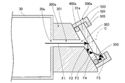
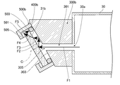
- FIG. 3 is a diagram showing a schematic configuration example around the window and the window holder on the output coupling mirror side in the comparative example.
- FIG. 4 is a diagram showing a schematic configuration example around the window and the window holder on the output coupling mirror side in the comparative example.
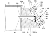
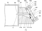
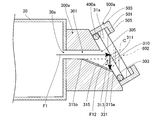
- FIG. 5 is a diagram showing a schematic configuration example around the window and the window holder on the output coupling mirror side in the first embodiment.
- FIG. 1 is a schematic diagram showing a schematic configuration example of the entire electronic device manufacturing apparatus.
- FIG. 2 is a schematic diagram showing a schematic configuration example of the entire gas laser device.
- FIG. 3 is a diagram showing a schematic configuration example around the window and the window holder on the output coupling mirror side in the comparative example.
- FIG. 4 is a diagram showing a schematic configuration example around the window and
- FIG. 6 is a schematic perspective view of the window holder when viewed from the end face side of the window holder.
- FIG. 7 is a diagram showing a schematic configuration example around the window and the window holder on the output coupling mirror side in the second embodiment.
- FIG. 8 is a diagram showing a schematic configuration example around the window and the window holder in the modified example of the second embodiment.
- FIG. 9 is a diagram showing a schematic configuration example around the window and the window holder in another modification of the second embodiment.
- FIG. 10 is a diagram showing a schematic configuration example around the window and the window holder on the output coupling mirror side in the third embodiment.
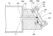
- FIG. 11 is a diagram showing a schematic configuration example around the window and the window holder on the output coupling mirror side in the fourth embodiment.
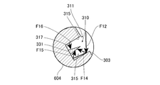
- FIG. 12 is a diagram showing a schematic configuration example around the window and the window holder on the output coupling mirror side in the fifth embodiment.
- FIG. 13 is a schematic view of a region surrounded by a solid circle in the
- FIG. 1 is a schematic diagram showing an overall schematic configuration example of the electronic device manufacturing equipment used in the electronic device exposure process.
- the manufacturing apparatus used in the exposure process includes a gas laser apparatus 100 and an exposure apparatus 200.
- the exposure apparatus 200 includes an illumination optical system 210 including a plurality of mirrors 211, 212, 213 and a projection optical system 220.
- the illumination optical system 210 illuminates the reticle pattern of the reticle stage RT with the laser beam incident from the gas laser device 100.
- the projection optical system 220 reduces-projects the laser beam transmitted through the reticle and forms an image on a workpiece (not shown) arranged on the workpiece table WT.
- the workpiece is a photosensitive substrate such as a semiconductor wafer coated with a photoresist.
- the exposure apparatus 200 exposes the workpiece to a laser beam reflecting the reticle pattern by moving the reticle stage RT and the workpiece table WT in parallel in synchronization with each other.
- a semiconductor device which is an electronic device, can be manufactured by transferring a device pattern to a semiconductor wafer by the exposure process as described above.
- FIG. 2 is a schematic diagram showing a schematic configuration example of the entire gas laser apparatus 100 of this example.
- the gas laser apparatus 100 of this example includes a housing 10, a laser oscillator LO, a wavelength measurement module 20, and a processor 70 as main configurations.
- the gas laser apparatus 100 of this example is an ArF excimer laser apparatus using a mixed gas containing, for example, argon (Ar), fluorine (F 2), and neon (Ne). In this case, the gas laser apparatus 100 emits a pulsed laser beam having a center wavelength of about 193 nm.
- the gas laser device 100 may be a gas laser device other than the ArF excimer laser device, and is, for example, a KrF excimer laser device using a mixed gas containing krypton (Kr), fluorine (F 2), and neon (Ne). May be.
- the gas laser apparatus 100 emits a pulsed laser beam having a center wavelength of about 248 nm.
- a mixed gas containing the laser media Ar, F 2 , and Ne and a mixed gas containing the laser media Kr, F 2 , and Ne may be referred to as a laser gas.
- the processor 70 of the present disclosure is a processing device including a storage device in which a control program is stored and a CPU for executing the control program.
- the processor 70 is specially configured or programmed to perform the various processes contained in the present disclosure.
- the processor 70 controls some configurations of the gas laser device 100. Further, the processor 70 controls the entire gas laser apparatus 100.
- the laser oscillator LO mainly includes a chamber device CH, a charger BC, a narrow band module 60, and an output coupling mirror OC.
- the chamber device CH includes a housing 30, a pair of windows 31a and 31b, a pair of window holders 300a and 300b described later, a pair of sealing members 400a and 400b described later, and a pair of fixing units 500a and 500b described later.
- a pair of electrodes 32a and 32b, an insulating portion 33, a pulse power module 35, an electrode holder portion 36, a cross flow fan 38, and a motor 38M are mainly provided.
- the window 31a and the window 31b are provided at positions facing each other in the housing 30.
- the window 31a is located on one end side in the traveling direction of the laser beam in the housing 30, and the window 31b is located on the other end side in the traveling direction of the laser beam in the housing 30.
- the light oscillates on the optical path including the housing 30 and the laser light is emitted. Therefore, the laser light generated in the internal space of the housing 30 passes through the window 31a and the window 31b. It emits light to the outside of the housing 30.
- the windows 31a and 31b are tilted so as to form a Brewster angle with respect to the traveling direction of the laser beam so that the reflection of the P-polarized light of the laser beam is suppressed.
- the housing 30 includes an internal space in which light is generated by the excitation of the laser gas.
- the laser gas is supplied from a laser gas supply source (not shown) arranged in the housing 10 to the internal space of the housing 30 via a pipe (not shown).
- a laser gas supply source not shown
- the gas laser device 100 is an ArF excimer laser device, for example, a mixed gas containing Ar, F 2 , and Ne is supplied from the laser gas supply source to the internal space of the housing 30.
- the gas laser device 100 is a KrF excimer laser, for example, a mixed gas containing Kr, F 2 , and Ne is supplied from the laser gas supply source to the internal space of the housing 30.
- the above-mentioned light generated by the excitation of the laser gas is emitted from the holes 30a described later in the housing 30, passes through the hollow portions of the cylindrical window holders 300a and 300b, and travels to the windows 31a and 31b.
- the longitudinal direction of the pair of electrodes 32a and 32b is along the traveling direction of the laser beam, and the pair of electrodes 32a and 32b are arranged so as to face each other in the internal space of the housing 30.
- the space between the electrodes 32a and 32b in the housing 30 is sandwiched between the windows 31a and the windows 31b.
- the electrodes 32a and 32b are discharge electrodes for exciting the laser medium by glow discharge.
- the electrode 32a is the cathode and the electrode 32b is the anode.
- An opening is formed in the housing 30, and this opening is closed by an insulating portion 33 formed including an insulator.
- the electrode 32a is supported by the insulating portion 33.
- a feedthrough 34 made of a conductive member is embedded in the insulating portion 33. The feedthrough 34 applies a voltage supplied from the pulse power module 35 to the electrode 32a.
- the electrode 32b is supported by the electrode holder portion 36 and is electrically connected to the electrode holder portion 36.
- the electrode holder portion 36 is electrically connected to the housing 30 via wiring (not shown).
- a charger BC arranged outside the housing 30 is connected to the pulse power module 35.
- the charger BC is a DC power supply device that charges a capacitor (not shown) provided in the pulse power module 35 with a predetermined voltage.
- the pulse power module 35 includes a switch controlled by the processor 70. When the switch is turned from off to on, the pulse power module 35 boosts the voltage applied from the charger BC to generate a pulsed high voltage, and applies this high voltage to the pair of electrodes 32a and 32b.
- a cross flow fan 38 is arranged in the internal space of the housing 30 on the side opposite to the electrode 32b side with respect to the electrode holder portion 36.
- the space in which the cross flow fan 38 is arranged in the internal space of the housing 30 communicates with the space between the pair of electrodes 32a and 32b in the internal space of the housing 30. Therefore, as the cross-flow fan 38 rotates, the laser gas enclosed in the internal space of the housing 30 circulates in a predetermined direction.
- a motor 38M arranged outside the housing 30 is connected to the cross-flow fan 38. As the motor 38M rotates, the cross flow fan 38 rotates. The motor 38M is turned on, off, and the rotation speed is adjusted by the control of the processor 70. Therefore, the processor 70 can adjust the circulation speed of the laser gas circulating in the internal space of the housing 30 by controlling the motor 38M.
- a heat exchanger (not shown) is placed beside the cross flow fan 38. At least a part of the laser gas circulated by the cross flow fan 38 passes through this heat exchanger, and the temperature of the laser gas is regulated by the heat exchanger.
- An optical path tube 51 is connected to one end side of the housing 30 where the window 31a is provided.
- the output coupling mirror OC is provided on one end side of the housing 30 as a reference, and is arranged in the internal space of the optical path tube 51.
- the output coupling mirror OC is an optical element to which the laser beam emitted from the window 31a is incident, and transmits a part of the light emitted from the window 31a and reflects the other part through the window 31a. Return to the internal space of the housing 30.
- the output coupling mirror OC is composed of, for example, an element in which a dielectric multilayer film is formed on a calcium fluoride substrate. A film that partially reflects the laser beam may be formed on the surface of the output coupling mirror OC.
- An optical path tube 52 is connected to the other end side of the housing 30 where the window 31b is provided.
- the narrowing band module 60 is connected to the optical path tube 52. Therefore, the narrowing band module 60 is provided on the other end side of the housing 30 as a reference, and is provided on the opposite side of the output coupling mirror OC with respect to the housing 30.
- the narrow band module 60 includes a housing 61, a grating 62, and prisms 63 and 64.
- An opening is formed in the housing 61, and the internal space of the housing 61 and the internal space of the optical path tube 52 communicate with each other through the opening.
- the grating 62 and the prisms 63 and 64 are arranged in the internal space of the housing 61.
- the grating 62 and the prisms 63 and 64 are optical elements to which the laser beam emitted from the window 31b is incident.
- the grating 62 is retrowed so that the incident angle and the diffraction angle of the laser beam substantially match.
- the grating 62 may be an escher grating blazeed for a wavelength of about 193 nm.
- the grating 62 is fixed to the housing 61 and does not move with respect to the housing 61.
- At least one of the prisms 63 and 64 is fixed on a rotating stage (not shown) arranged in the internal space of the housing 61.
- the prism fixed on the rotating stage rotates slightly to adjust the incident angle of the light incident on the grating 62.
- the wavelength of the light reflected by the grating 62 and incident on the chamber device CH is adjusted. Therefore, the wavelength of the light returning to the housing 30 is adjusted to a desired wavelength by reflecting the light emitted from the window 31b of the housing 30 by the grating 62 via the prisms 63 and 64.
- Each prism 63, 64 is composed of, for example, calcium fluoride.
- the number of prisms arranged in the narrow band module 60 is two in this example, but it may be one or three or more.
- a laser resonator is configured by an output coupling mirror OC provided with the housing 30 interposed therebetween and a grating 62, and the housing 30 is arranged on the optical path of the laser resonator. Therefore, the light emitted from the internal space of the housing 30 through the hole of the housing 30 described later is the grating 62 of the narrowing module 60 and the output coupling mirror OC via the windows 31a and 31b and the prisms 63 and 64. Round trip between.
- the reciprocating light is amplified each time it passes through the laser gain space between the electrodes 32a and 32b. A part of the amplified light passes through the output coupling mirror OC through the window 31a and is emitted as pulsed laser light.
- the wavelength measurement module 20 is arranged on the optical path of the pulsed laser light emitted from the output coupling mirror OC of the laser oscillator LO.
- the wavelength measurement module 20 includes a housing 21, a beam splitter 22, and a wavelength monitor 23.
- the housing 21 is connected to the optical path tube 51.
- An opening is formed in the housing 21, and the internal space of the housing 21 and the internal space of the optical path tube 51 communicate with each other through the opening.
- a beam splitter 22 and a wavelength monitor 23 are arranged in the internal space of the housing 21.
- the beam splitter 22 and the wavelength monitor 23 are optical elements to which the pulsed laser light emitted from the output coupling mirror OC is incident.
- the beam splitter 22 transmits the pulsed laser light emitted from the laser oscillator LO with high transmittance, and reflects a part of the pulsed laser light toward the light receiving surface of the wavelength monitor 23.
- the wavelength monitor 23 detects the wavelength of the pulsed laser light incident on the light receiving surface, and outputs data related to the detected wavelength to the processor 70.
- An opening is formed on the side of the housing 21 of the wavelength measurement module 20 opposite to the side to which the optical path tube 51 is connected, and the optical path tube 53 is connected so as to surround the opening. Therefore, the internal space of the optical path tube 51, the internal space of the housing 21, and the internal space of the optical path tube 53 communicate with each other.
- the optical path tube 53 is connected to the housing 10.
- a laser beam emitting window OW is provided at a position surrounded by the optical path tube 53 in the housing 10. Therefore, the light that passes through the beam splitter 22 of the wavelength measurement module 20 is emitted to the outside of the housing 10 from the laser light emission window OW via the optical path tube 53.
- the internal spaces of the optical path tubes 51, 52, 53 and the housings 21, 61 are filled with purge gas.
- the purge gas contains an inert gas such as high-purity nitrogen having few impurities such as oxygen.
- the purge gas is supplied from a purge gas supply source (not shown) arranged outside the housing 10 to the optical path tubes 51, 52, 53 and the internal space of the housings 21 and 61 through a pipe (not shown).
- an exhaust device for exhausting the laser gas exhausted from the internal space of the housing 30 of the chamber device CH is arranged.
- the exhaust device performs a process of removing the F 2 gas from the gas exhausted from the internal space of the housing 30 by a halogen filter, and discharges the gas to the housing 10.
- FIG. 3 is a diagram showing a schematic configuration example of the window 31a and the window holder 300a in the comparative example.
- the window 31a and the window holder 300a are shown in a vertical cross section.
- the light traveling from the internal space of the housing 30 to the window 31a through the hole 30a, the hollow portion 301, and the opening 305 of the housing 30 is indicated by the solid arrow F1.
- the window holder 300a has a tubular shape and is located between the one end of the housing 30 and the window 31a. In FIG. 3, one end of the window holder 300a is connected to the wall surface of the housing 30, and the other end of the window holder 300a is located on the window 31a side.
- the tubular window holder 300a includes a hollow portion 301 and an end surface 303 located at the other end of the window holder 300a.
- the hollow portion 301 communicates with the internal space of the housing 30 through the hole 30a of the housing 30. Further, the hollow portion 301 communicates with the opening 305 located at the end face 303. Light traveling from the internal space of the housing 30 to the output coupling mirror OC passes through the hole 30a, the opening 305, and the window 31a of the housing 30 through the hollow portion 301. Further, contrary to the above, the light traveling from the output coupling mirror OC to the internal space of the housing 30 also passes through the hollow portion 301. Therefore, the opening 305 is not only an exit port for light to the output coupling mirror OC, but also an entrance port for light to the hollow portion 301.
- the end face 303 is arranged so as to face the window 31a. Further, the end surface 303 is arranged parallel to the surface of the facing window 31a. Hereinafter, the surface may be referred to as a laser gas side surface in contact with the laser gas. Like the end face 303, the opening 305 is also arranged parallel to the surface of the window 31a.
- the end face 303 is a plane.
- the window 31a is located in the projection area plane of the end face 303 projected toward the window 31a along a straight line orthogonal to the end face 303.
- the window 31a is a parallel plane substrate.
- the window 31a is made of calcium fluoride.
- the window 31a may be a parallel wedge substrate. Further, the window 31a may be made of a member having a high transmittance in the ultraviolet region such as magnesium fluoride, molten quartz, or synthetic quartz.
- the window 31a is arranged so that the light traveling through the hollow portion 301 is incident at a predetermined angle. This angle is an angle near the Brewster's angle, for example, 55 ° to 61 °. Further, the window 31a is held by the window holder 300a in a state where the surface of the window 31a on which the light is incident is inclined with respect to the optical axis of the light indicated by the solid arrow F1 traveling through the hollow portion 301.
- a sealing member 400a and a fixing unit 500a are arranged around the window 31a and the window holder 300a.
- the configurations of the ring-shaped sealing member 400a and the fixing unit 500a will be described.
- the sealing member 400a is arranged between the end face 303 and the window 31a so as to be sandwiched between the end face 303 and the window 31a.
- the sealing member 400a is arranged so as to surround the central axis C of the window 31a and the opening 305 of the end surface 303. Therefore, the inner diameter of the sealing member 400a is larger than the diameter of the opening 305 of the end face 303.
- the outer diameter of the sealing member 400a is substantially the same as the outer diameter of the window 31a, and the sealing member 400a is arranged on the outer peripheral edge of the surface of the window 31a in contact with the laser gas.
- the sealing member 400a is an O-ring made of a resin such as nitrile rubber.
- the sealing member 400a may be arranged so as to surround the opening 305 in the end face 303, the outer diameter of the sealing member 400a is smaller than the outer diameter of the window 31a, and the sealing member 400a is the opening 305 and the window 31a. It may be arranged between the outer peripheral edge and the outer peripheral edge.
- the sealing member 400a is in close contact with the surface of the window 31a and the end surface 303 of the window holder 300a. Therefore, it can be understood that the window holder 300a holds the window 31a on the end face 303 via the sealing member 400a.
- the sealing member 400a seals between the surface of the window 31a and the end surface 303 of the window holder 300a by close contact. As a result, the laser gas is enclosed in the internal space of the housing 30, the hollow portion 301, and the space between the end face 303 and the window 31a.
- the fixing unit 500a fixes the sealing member 400a and the window 31a to the window holder 300a.
- the fixing unit 500a includes a ring member 501 and a fixing member 503.
- the ring member 501 is arranged on the surface of the window 31a on the side opposite to the sealing member 400a side, and is arranged so as to surround the central axis C of the window 31a.
- the surface may be referred to as a purge gas side surface in contact with the purge gas.
- the inner diameter of the ring member 501 is substantially the same as the inner diameter of the sealing member 400a, and the outer diameter of the ring member 501 is substantially the same as the outer diameter of the sealing member 400a. Further, the ring member 501 is arranged on the outer peripheral edge of the surface of the window 31a in contact with the purge gas.
- the ring member 501 is arranged on the side opposite to the sealing member 400a with respect to the window 31a, and the window 31a is arranged sandwiched between the sealing member 400a and the ring member 501.
- the central axes of the ring member 501, the window 31a, and the sealing member 400a are arranged coaxially.
- the fixing member 503 has a tubular shape.
- the inner diameter of the fixing member 503 is substantially the same as the outer diameter of each of the window 31a, the sealing member 400a, and the ring member 501.
- the fixing member 503 surrounds the outer peripheral surfaces of the window 31a, the sealing member 400a, and the ring member 501 over the entire circumference, and is in contact with the outer peripheral surfaces thereof.
- the fixing member 503 may be in close contact with each outer peripheral surface.
- the central axis of the fixing member 503 is located coaxially with the central axis C of the window 31a.
- a fixing member 503 that surrounds the outer peripheral surfaces of the window 31a, the sealing member 400a, and the ring member 501 over the entire circumference is attached to the end surface 303 at one end of the fixing member 503.
- the fixing member 503 includes a ring-shaped inner flange portion 505 arranged at the other end of the fixing member 503.
- the inner flange portion 505 is arranged over the entire circumference of the inner peripheral surface of the fixing member 503. Further, the inner flange portion 505 extends from the inner peripheral surface of the fixing member 503 toward the center of the fixing member 503 in the radial direction of the fixing member 503.
- the inner diameter of the inner flange portion 505 is substantially the same as the inner diameter of the ring member 501.
- the fixing member 503 When the fixing member 503 is attached to the end face 303, the inner flange portion 505 presses the ring member 501 toward the window 31a. As a result, the window 31a is pressed toward the end surface 303 via the sealing member 400a and is fixed in the axial direction and the radial direction of the window 31a. Further, the fixing member 503 fixes the window 31a in the radial direction of the window 31a by abutting on the outer peripheral surface of the window 31a.
- the sealing member 400a is elastically deformed by pressing, and the contact surface of the sealing member 400a with respect to the window 31a and the end surface 303 is expanded by elastic deformation as compared with before pressing. As a result, the sealing member 400a is in close contact with the window 31a as compared with that before pressing, and the contact between the surface of the window 31a on the laser gas side and the end surface 303 of the window holder 300a is further sealed.
- the window holder 300a and the ring member 501 are made of metal.
- This metal is stainless steel, for example, SUS304, SUS316, or SUS303.
- the end surface 303 of the window holder 300a facing the window 31a and the contact surface of the ring member 501 in contact with the window 31a among the ring members 501 are mirror-polished.
- the configurations of the window 31b, the window holder 300b, the sealing member 400b, and the fixing unit 500b are the same as the configurations of the window 31a, the window holder 300a, the sealing member 400a, and the fixing unit 500a, respectively.
- the arrangement of the window holder 300b with respect to the housing 30 is such that the window holder 300b is arranged on the other end side of the housing 30 and the window holder 300b is the light indicated by the arrow F1. Since it is the same as the arrangement of the window 31a with respect to the housing 30, except that the window 31a is arranged upside down with respect to the optical axis, detailed description thereof will be omitted.
- the internal space of the optical path tubes 51, 52, 53 and the internal space of the housings 21, 61 are filled with purge gas from a purge gas supply source (not shown). Further, laser gas is supplied to the internal space of the housing 30 from a laser gas supply source (not shown). When the laser gas is supplied, the processor 70 controls the motor 38M to rotate the cross flow fan 38, and the rotation of the cross flow fan 38 circulates the laser gas.
- the processor 70 controls a switch in the charger BC and the pulse power module 35 to apply a high voltage between the electrodes 32a and 32b.
- a high voltage is applied between the electrodes 32a and 32b, the insulation between the electrodes 32a and 32b is destroyed and a discharge occurs. Due to the energy of this discharge, the laser medium contained in the laser gas between the electrodes 32a and 32b is brought into an excited state and emits spontaneous emission light when returning to the ground state.
- a part of this light is ultraviolet light, which is emitted from the light of the housing 30 and passes through the window 31b through the hollow portion 301 and the opening 305 in the window holder 300b.
- the transmitted light is magnified in the traveling direction of the light by passing through the prisms 63 and 64 and guided to the grating 62.
- the light is wavelength-dispersed as it passes through the prisms 63 and 64, respectively. Further, the light is incident on the grating 62 at a predetermined angle and diffracted, and the light having a predetermined wavelength is reflected by the grating 62 at the same reflection angle as the incident angle.
- the light reflected by the grating 62 passes through the prisms 63 and 64, and again from the window 31b through the opening 305 of the window holder 300b, the hollow portion 301, and the hole 30a of the housing 30, and the internal space of the housing 30. Propagate to.
- the light propagating in the internal space of the housing 30 is narrowed by the narrow band module 60. Due to this narrowed band light, the excited laser medium causes stimulated emission and the light is amplified.
- Light is emitted from the hole 30a of the housing 30, passes through the window 31a through the hollow portion 301 and the opening 305 in the window holder 300a, and travels to the output coupling mirror OC. A part of the light is transmitted through the output coupling mirror OC, and the remaining part of the light is reflected by the output coupling mirror OC to form an opening 305 of the window holder 300a, a hollow portion 301, and a hole 30a of the housing 30 from the window 31a. It propagates to the internal space of the housing 30 through the housing 30.
- the light propagating in the internal space of the housing 30 passes through the window 31b and the prisms 63 and 64 and travels to the grating 62 as described above. In this way, light of a predetermined wavelength reciprocates between the grating 62 and the output coupling mirror OC. Therefore, the light is amplified and laser oscillation occurs. Then, a part of the laser beam passes through the output coupling mirror OC and is emitted from the laser beam emitting window OW toward the exposure apparatus 200.
- a part of the laser light transmitted through the output coupling mirror OC is reflected by the beam splitter 22.
- the reflected laser light is received by the wavelength monitor 23, and the wavelength monitor 23 outputs a signal based on the energy intensity of the received laser light to the processor 70.
- the processor 70 controls the charger BC and the pulse power module 35 to adjust the power of the emitted laser beam.
- the outer peripheral side includes the outer peripheral surface of the window 31a, the laser gas side surface of the window 31a, and the outer peripheral edge side of the purge gas side surface.
- the member is a member arranged so as not to hinder the progress of light transmitted through the window 31a and reciprocating in the laser cavity, and is a sealing member 400a, a ring member 501, and a fixing member 503. .
- the reflected light may pass through the window 31a and travel to the ring member 501 as indicated by the solid arrow F4.
- the reflected light does not travel to the entire surface of the ring member 501 that abuts on the purge gas side surface of the window 31a, but is a part of the surface of the ring member 501 located in the reflection side region of the surface of the ring member 501. Proceed to. A part of the surface substantially corresponds to the bottom of the lower semicircular arc when the ring member 501 is divided into upper and lower semicircular arcs when the ring member 501 is viewed from the front. Further, the reflected light may be reflected by the part of the surface of the ring member 501, pass through the window 31a as shown by the solid arrow F5, and travel to the sealing member 400a.
- the reflected light does not travel to the entire contact surface of the sealing member 400a that is in close contact with the surface of the window 31a on the laser gas side, but the sealing member located in the reflection side region of the contact surface of the sealing member 400a. It progresses to a part of the contact surface of 400a.
- the part of the contact surface faces a part of the surface of the ring member 501 irradiated with the reflected light.
- the reflectance of the surface of the window 31a may be higher than expected, or the intensity of the reflected light may be higher than expected.
- the sealing member 400a that is irradiated with the reflected light for a predetermined time or longer deteriorates earlier than a predetermined period, and there is a concern that the useful life of the sealing member 400a becomes shorter than the predetermined period. ..
- the usable period of the gas laser device 100 which indicates the interval from the maintenance of the gas laser device 100 to the next maintenance of the maintenance, may be shorter than the period assumed in advance.
- the window holder 300a side has been described, but even on the window holder 300b side, a part of the light traveling from the housing 30 to the window 31b via the window holder 300b is reflected by the surface of the window 31b. Since the window holder 300b is arranged upside down with the window holder 300a as described above, the reflection direction of the window 31b is opposite to the reflection direction of the window 31a. As described above, the reflected light may travel to the sealing member 400b on the window holder 300b side via the ring member 501 in the end surface 303 of the window holder 300b and the fixing unit 500b on the window holder 300b side.
- the sealing member 400b also deteriorates earlier than the predetermined period, and there is a concern that the useful life of the sealing member 400b becomes shorter than the predetermined period.
- the usable period of the gas laser apparatus 100 may be shorter than the period assumed in advance.
- the gas laser apparatus 100 in which the usable period can be suppressed to be shorter than the period assumed in advance is exemplified by suppressing the deterioration of the sealing members 400a and 400b.
- the window 31a and the window holder 300a on the output coupling mirror OC side will be described, but the window 31b and the window holder 300b on the grating 62 side will also be described as the window 31a. And the same configuration, action, and effect as the window holder 300a can be obtained.
- FIG. 5 is a diagram showing a schematic configuration example around the window 31a and the window holder 300a in the present embodiment.
- the window 31a and the window holder 300a are shown in a vertical cross section.
- FIG. 6 is a schematic perspective view of the window holder 300a when viewed from the end surface 303 side of the window holder 300a of the present embodiment.
- the configurations of the window holders 300a and 300b are mainly different from the configurations of the window holders 300a and 300b of the comparative example.
- the configuration of the window holder 300a is the same as the configuration of the window holder 300b.
- the arrangement of the window holder 300b of the present embodiment with respect to the housing 30 is such that the window holder 300b is arranged on the other end side of the housing 30 and the window holder.
- the difference from the window holder 300a of the comparative example will be described using the window holder 300a.
- the recessed portion 310 is continuous with the end surface 303 of the window holder 300a in the present embodiment.
- the recessed portion 310 is continuous with the region of the end face 303 surrounded by the sealing member 400a.
- the recessed portion 310 is located in the region on the reflection direction side of the reflected light reflected by the window 31a among the light traveling from the opening 305 to the window 31a.
- the reflected light is indicated by a solid arrow F12.
- the recessed portion 310 is recessed from the end face 303 toward the hollow portion 301 and communicates with the hollow portion 301.
- the opening 311 of the recessed portion 310 is continuous with the opening 305 and is surrounded by the sealing member 400a. Further, the opening 311 is parallel to the window 31a.
- the pair of side surfaces 313 of the recessed portion 310 is a planar inner wall surface of the recessed portion 310, which is orthogonal to the end surface 303 and faces each other.
- the pair of side surfaces 313 are continuous with the end surface 303 and the inner peripheral surface of the window holder 300a in the hollow portion 301.
- the recessed portion 310 includes an extending surface 315 that is continuous with the end surface 303 and extends in a direction away from the window 31a.
- the extending surface 315 is located on the reflection direction side of the reflected light reflected by the window 31a, and is a flat bottom surface of the recessed portion 310 to which the reflected light from the window 31a is directly irradiated.
- the extending surface 315 includes one end 315a continuous with the end surface 303 and the other end 315b continuous with the inner peripheral surface of the window holder 300a in the hollow portion 301. Therefore, it can be understood that one end 315a is located at a position away from the optical axis of the light indicated by the solid arrow F1, and the other end 315b is located near the optical axis of the light indicated by the solid arrow F1.
- the tilt angle of the extending surface 315 with respect to the window 31a is larger than the tilt angle of the end face 303 with respect to the window 31a.
- the inclination angle of the extending surface 315 with respect to the window 31a is the intersection of the other end 315b of the extending surface 315, the straight line passing through the other end 315b and the one end 315a of the extending surface 315, and the surface of the window 31a on the laser gas side, and the window 31a. It is an angle formed by three points with the center of the surface on the laser gas side of. The intersection may be the intersection of the straight line and the widened region when the surface on the laser gas side is widened in the plane direction of the surface on the laser gas side.
- the tilt angle of the end face 303 with respect to the window 31a is zero because the end face 303 is arranged parallel to the window 31a. Therefore, it can be understood that the other end 315b side of the extending surface 315 is tilted in a counterclockwise direction, which is a direction away from the window 31a with respect to the end surface 303, about one end 315a of the extending surface 315. Further, it can be understood that the distance between the extending surface 315 and the window 31a gradually increases from one end 315a toward the other end 315b.
- the distance between one end 315a of the extending surface 315 and the window 31a is the same as the distance between the end surface 303 and the window 31a in the direction along the normal line 600 described later, but the other end of the extending surface 315. It is shorter than the distance between the 315b and the window 31a. Further, the extending surface 315 does not extend in parallel with the optical axis of the light indicated by the solid arrow F1, but is also inclined with respect to the optical axis.
- the window holder 300a of the present embodiment is made of a metal such as stainless steel, like the window holder 300a of the comparative example. Therefore, the extending surface 315 reflects the reflected light traveling from the window 31a to the extending surface 315. Further, when the extending surface 315 is positioned at an angle as described above, the extending surface 315 reflects the reflected light traveling from the window 31a to the extending surface 315 toward the window 31a via the inside of the sealing member 400a. do. In the present embodiment, the extending surface 315 has the normal line 600 in the window 31a from the outer peripheral side of the window 31a to the central axis C side of the window 31a in the direction from the extending surface 315 toward the window 31a.
- the reflected light is reflected toward the window 31a so as to straddle the window 31a and enter the window 31a.
- the reflected light reflected by the extending surface 315 and incident on the window 31a is indicated by the solid arrow F13.
- the normal line 600 is a line passing through the extending surface 315 among the plurality of normal lines on the surface of the window 31a on the laser gas side.
- the intersection of the normal line 600 and the extending surface 315 is the intersection of the irradiation position of the reflected light on the extending surface 315 and the normal line of the window 31a passing through the irradiation position of the light indicated by the arrow F1 and the extending surface 315. It is located between and.
- the irradiation position of the reflected light on the extending surface 315 and the line passing through the window 31a are used as reference lines.
- the reference line is a line perpendicular to the extending surface 315.
- the line 602 is a virtual line located at a position where the optical axis of the reflected light is symmetrically folded back at the irradiation position of the reflected light on the extending surface 315 with respect to the reference line.
- a solid line of an arrow F13 indicating reflected light overlaps a part of the virtual line 602.
- the virtual line 602 makes the normal line 600 in the window 31a from the outer peripheral side of the window 31a to the central axis side of the window 31a in the direction from the extending surface 315 toward the window 31a. It can be understood that it is located straddling toward.
- the width of the extending surface 315 is shorter than the maximum width of the rounded rectangular opening 305, and is the same as the length of the straight line portion in the rounded rectangular opening 305. ..
- the width of the extending surface 315 is also the width of the opening 311 and the distance between the pair of side surfaces 313.
- the extending surface 315 has a rectangular shape such as a rectangular shape.
- the extending surface 315 is orthogonal to the pair of side surfaces 313.
- the gas laser device 100 of the present embodiment as in the gas laser device 100 of the comparative example, as shown by the arrow F1 in FIG. 5, light is transmitted from the internal space of the housing 30 to the holes 30a and the hollow portion 301 of the housing 30. And through the opening 305 to the window 31a. When this light passes through the window 31a, a part of the light is reflected by the surface of the window 31a as in the comparative example. In FIG. 5, the reflected light travels from the surface of the window 31a to the recess 310 as indicated by the solid arrow F12. Further, the reflected light travels from the opening 311 of the recessed portion 310 to the inside of the recessed portion 310 and directly travels to the extending surface 315 of the recessed portion 310.
- the light indicated by the solid arrow F1 and the reflected light indicated by the solid line F12 pass through the inside of the sealing member 400a.
- the surface of the window 31a on the laser gas side is inclined with respect to the direction along the optical axis of the light indicated by the solid arrow F1, the end surface 303 is arranged parallel to the window 31a, and the side surface 313 is orthogonal to the end surface 303. Therefore, when looking at the reflected light indicated by the solid arrow F12 along the light indicated by the solid arrow F1, the reflected light indicated by the arrow F12 passes between the pair of side surfaces 313 and travels to the extending surface 315. , The progress from the window 31a to the side surface 313 is suppressed.
- the virtual line 602 straddles the normal line 600 in the window 31a from the outer peripheral side of the window 31a toward the central axis side of the window 31a in the direction from the extending surface 315 toward the window 31a.
- the extending surface 315 reflects the reflected light
- the progress of the reflected light to a part of the surface of the ring member 501 and a part of the inner peripheral surface of the fixing member 503 is suppressed.
- the window holder 300a including the extending surface 315 is made of metal, the reflected light is reflected by the extending surface 315.
- the reflected light is reflected toward the window 31a by the extending surface 315, passes through the inside of the sealing member 400a, and is incident on the window 31a. .. Further, since the extending surface 315 is positioned at an angle as described above, as shown by the arrow F13, the reflected light has a normal line 600 on the outer peripheral side of the window 31a in the direction from the extending surface 315 toward the window 31a. It travels across the window 31a toward the central axis C side and passes through the window 31a. The traveling direction of the reflected light is on the opposite region side.
- the opposite region is located on the opposite side of the reflection side region located on the reflection direction side of the reflected light reflected by the window 31a with reference to the light irradiation position indicated by the arrow F1 on the laser gas side surface of the window 31a.
- the reflected light traveling from the laser gas side surface of the window 31a to the purge gas side surface is suppressed from the central axis C side of the window 31a to the outer peripheral side of the window 31a by the extending surface 315 in the reflecting side region.
- the progress of the reflected light to a part of the surface of the ring member 501 located in the reflection side region and a part of the inner peripheral surface of the fixing member 503 is suppressed as compared with the case where the extending surface 315 is not formed.
- Ru A part of the surface of the ring member 501 located in the reflection side region and a part of the inner peripheral surface of the fixing member 503 are located on the side opposite to the reflection direction of the reflected light. Further, since the reflected light indicated by the solid arrow F13 is reflected by the extending surface 315 as described above, the progress from the extending surface 315 to the side surface 313 is suppressed.
- the sealing member 400a is arranged in close contact with the window 31a and the end face 303 of the window holder 300a, and is arranged so as to surround the opening 305.
- the extending surface 315 is located on the reflection direction side of the reflected light from the window 31a, extends continuously to the end surface 303 in the direction away from the window 31a, and is irradiated with the reflected light.
- the virtual line 602 straddles the normal line 600 in the window 31a from the outer peripheral side of the window 31a toward the central axis side of the window 31a in the direction from the extending surface 315 toward the window 31a.
- Members are generally arranged on the outer peripheral side of the window 31a so as not to obstruct the light transmitted through the window 31a, and in the present embodiment, the ring member 501 and the fixing member 503 are arranged.
- the virtual line 602 straddles the normal line 600 in the window 31a from the outer peripheral side of the window 31a toward the central axis side of the window 31a in the direction from the extending surface 315 toward the window 31a.
- the reflection of the reflected light by a part of the surface of the ring member 501 and a part of the inner peripheral surface of the fixing member 503 is suppressed.
- the irradiation of the sealing member 400a with the reflected light for a predetermined time or longer can be suppressed, and the deterioration of the sealing member 400a earlier than the predetermined period can be suppressed.
- the service life of the sealing member 400a is suppressed to be shorter than the period assumed in advance. Therefore, it can be suppressed that the usable period of the gas laser apparatus 100 becomes shorter than the period assumed in advance.
- the service life of the sealing member 400a is extended as compared with the case where the extending surface 315 is not formed.
- the gas laser apparatus 100 can be used in a state where the sealing is maintained in the internal space of the housing 30, the space between the hollow portion 301, the end face 303, and the window 31a. The period can be extended.
- the extending surface 315 is such that the reflected light straddles the normal line 600 from the outer peripheral side of the window 31a toward the central axis C side of the window 31a and is incident on the window 31a. In addition, it reflects the reflected light. As a result, deterioration of the sealing member 400a that is earlier than a predetermined period can be suppressed as compared with the case where the extending surface 315 does not reflect as described above.
- a part of the reflected light may be reflected by the purge gas side surface of the window 31a toward the laser gas side surface of the window 31a. .. Further, a part of the reflected light traveling on the laser gas side surface of the window 31a may be reflected toward the purge gas side surface of the window 31a by the laser gas side surface of the window 31a. When such reflection is repeated, the intensity of the reflected light traveling inside the window 31a is weakened.
- the reflected light transmitted through the window 31a returns to a part of the surface of the ring member 501 located on the outer peripheral side in the reflection side region and a part of the inner peripheral surface of the fixing member 503.
- the reflected light can be reflected more than in the comparative example.
- the number of reflections in the window 31a is larger than the number of reflections in the comparative example due to the extending surface 315 that is inclined and reflected as described above. Therefore, the intensity of the reflected light of the present embodiment traveling to the sealing member 400a is weaker than the intensity of the reflected light traveling to the sealing member 400a of the comparative example.
- the intensity of the reflected light is weakened, even if the reflected light reflected by the extending surface 315 advances from the inside of the window 31a to the sealing member 400a and irradiates the sealing member 400a, the sealing is earlier than expected. Deterioration of the stop member 400a can be suppressed.
- the extending surface 315 may be polished for reflection. Further, a reflective film thinly plated with a metal such as silver or aluminum may be arranged on the extending surface 315. The extending surface 315 may reflect the reflected light toward the inner peripheral surface of the window holder 300a in the hollow portion 301.
- FIG. 7 is a diagram showing a schematic configuration example around the window 31a and the window holder 300a in the present embodiment.
- the window 31a and the window holder 300a are shown in a vertical cross section.
- the configuration in the window 31a is different from the configuration in the window 31a of the first embodiment, and the other configurations are the same as those in the first embodiment.
- the gas laser apparatus 100 of the present embodiment further includes the films 321a and 321b in the configuration of the gas laser apparatus 100 of the first embodiment.
- the films 321a and 321b are included in the configuration of the window 31a.
- the film 321a is the first film arranged on the contact surface with the sealing member 400a on the surface of the window 31a on the laser gas side.
- the film 321a is arranged on the reflection direction side of the contact surface of the window 31a reflected by the window 31a, and is arranged on a part of the laser gas side surface of the window 31a located in the reflection side region.
- the film 321a abuts on a part of the sealing member 400a located in the reflection side region.
- the film 321a is mainly made of aluminum, and is a reflective film that reflects at least a part of the light having the same wavelength as the reflected light indicated by the arrow F13 toward the purge gas side surface of the window 31a and the outer peripheral surface of the window 31a. ..
- the film 321a is arranged, for example, by thin film deposition.
- the thickness of the film 321a is preferably about 200 nm.
- the film 321b is a second film arranged on the contact surface with the ring member 501 on the surface of the window 31a on the purge gas side.
- the film 321b is arranged on the reflection direction side of the contact surface of the window 31a reflected by the window 31a, and is arranged on a part of the purge gas side surface of the window 31a located in the reflection side region.
- the film 321b abuts on a part of the ring member 501 located in the reflection side region.
- the film 321b is mainly composed of aluminum oxide, and is an absorbent film that absorbs at least a part of light having the same wavelength as the reflected light indicated by the arrow F13.
- the film 321b is arranged, for example, by thin film deposition.
- the thickness of the film 321b is preferably about 200 nm.
- a part of the reflected light is the surface on the purge gas side of the window 31a due to the surface on the laser gas side of the window 31a. May be reflected towards. Further, a part of the reflected light traveling on the purge gas side surface of the window 31a may be reflected toward the laser gas side surface of the window 31a by the purge gas side surface of the window 31a.
- Such light is light having the same wavelength as the reflected light indicated by the arrow F13, and at least a part of the light is repeatedly reflected inside the window 31a.
- the film 321a on the surface side of the laser gas side of the window 31a is a reflective film, the light traveling to the film 321a among the reflected light that repeats the above reflection is transmitted to the outer peripheral surface of the window 31a and the film 321b on the surface side of the laser gas side of the window 31a. , And a part of the surface of the window 31a on the purge gas side.
- a part of the purge gas side surface is a region of the purge gas side surface where the ring member 501 is not arranged.
- the film 321b on the surface side of the purge gas side of the window 31a absorbs the light from the surface of the window 31a on the laser gas side or the light from the film 321a which is a reflective film among the reflected light that repeats the above reflection.
- the irradiation of the reflected light to the sealing member 400a is further suppressed by the film 321a, and the deterioration of the sealing member 400a earlier than the predetermined period is further suppressed.
- the service life of the sealing member 400a is further suppressed to be shorter than the period assumed in advance. Therefore, it can be further suppressed that the usable period of the gas laser apparatus 100 is shorter than the period assumed in advance.
- the film 321b also has the same action and effect as the film 321a.
- one of the film 321a on the surface side of the laser gas side of the window 31a and the film 321b on the surface side of the purge gas side of the window 31a may be a reflective film and the other may be an absorbing film.
- the absorbent film absorbs at least a part of the light traveling from the window 31a to the sealing member 400a.
- the reflective film is the surface on the laser gas side of the window 31a on which at least a part of the light is sealed and the surface on which the member 400a is arranged. It is reflected on the outer peripheral surface of the window 31a.
- the light has the same wavelength as the reflected light indicated by the arrow F13.
- both the film 321a on the surface side of the laser gas side of the window 31a and the film 321b on the surface side of the purge gas side of the window 31a may be a reflective film or an absorbing film.
- the film 321a on the laser gas side surface side of the window 31a may be arranged on the entire contact surface with the sealing member 400a on the laser gas side surface of the window 31a. Therefore, the film 321a is arranged in a ring shape like the ring-shaped sealing member 400a.
- the film 321b on the purge gas side surface side of the window 31a may be arranged on the entire contact surface with the ring member 501 on the purge gas side surface of the window 31a. Therefore, the film 321a is arranged in a ring shape like the ring member 501.
- the film 321b may not be arranged on the purge gas side surface of the window 31a, and only the film 321a may be arranged on the laser gas side surface of the window 31a.
- the film 321a may be a reflective film or an absorbent film.
- the film 321a may not be arranged on the surface of the window 31a on the laser gas side, and only the film 321b may be arranged on the surface of the window 31a on the purge gas side.
- the membrane 321b is an absorbing membrane.
- the reflective film may be a dielectric multilayer film.
- the absorbent film may be a film colored in black.
- a plate-shaped reflective member may be arranged instead of the reflective film, or a plate-shaped absorbent member may be arranged instead of the absorbent film.
- FIG. 10 is a diagram showing a schematic configuration example around the window 31a and the window holder 300a in the present embodiment.
- the window 31a and the window holder 300a are shown in a vertical cross section.
- the configuration of the window holder 300a is different from the configuration of the window holder 300a of the first embodiment, and the window holder 300a of the present embodiment absorbs the reflected light.
- the extending surface 315 is blackened and plated, and the extending surface 315 is an absorbing surface that absorbs the reflected light traveling from the window 31a to the extending surface 315. .. Most of the reflected light is converted into heat by the extending surface 315. The heat is released to the outside from the window holder 300a.
- the extending surface 315 absorbs the reflected light from the window 31a. Therefore, the progress of the reflected light from the extending surface 315 to the window 31a is suppressed, the irradiation of the light traveling from the window 31a to the sealing member 400a is further suppressed, and the deterioration of the sealing member 400a is faster than the predetermined period. Is more suppressed.
- the service life of the sealing member 400a is further suppressed to be shorter than the period assumed in advance. Therefore, it can be further suppressed that the usable period of the gas laser apparatus 100 is shorter than the period assumed in advance.
- the window holder 300a is provided with the extending surface 315 which is the absorbing surface, the number of parts can be reduced as compared with the case where another member having the absorbing surface is arranged on the extending surface 315.
- FIG. 11 is a diagram showing a schematic configuration example around the window 31a and the window holder 300a in the present embodiment.
- the window 31a and the window holder 300a are shown in a vertical cross section.
- the configuration of the window holder 300a is different from the configuration of the window holder 300a of the third embodiment, and the window holder 300a further includes the absorbing member 331 in the configuration of the window holder 300a of the third embodiment.
- the absorption member 331 has a plate shape and is arranged on the extending surface 315.
- the absorbing member 331 is laminated and arranged on the entire extending surface 315.
- the absorbing member 331 is arranged inside the recessed portion 310.
- the absorption member 331 is mainly made of aluminum oxide, and absorbs the reflected light traveling from the window 31a to the absorption member 331.
- the thickness of the absorbing member 331 is preferably about 0.3 mm.
- the absorption member 331 may be composed of a member colored in black.
- the absorption member 331 absorbs the reflected light from the window 31a. Therefore, the progress of the reflected light from the absorption member 331 to the window 31a is suppressed, the irradiation of the light traveling from the window 31a to the sealing member 400a is further suppressed, and the deterioration of the sealing member 400a is earlier than the presumed period. It is more suppressed.
- the service life of the sealing member 400a is further suppressed to be shorter than the period assumed in advance. Therefore, it can be further suppressed that the usable period of the gas laser apparatus 100 is shorter than the period assumed in advance.
- the absorbent member 331 is separate from the window holder 300a, it is possible to reduce the trouble of black-plating the window holder 300a.
- the absorption member 331 may be arranged at the irradiation position of the reflected light on the extending surface 315.
- the absorption member 331 may also be arranged on the side surface 313 as long as the light from the window 31a travels to the side surface 313.
- the window holder 300a including the side surface 313 and the extending surface 315 may be configured as the absorbing member 331.
- FIG. 12 is a diagram showing a schematic configuration example around the window 31a and the window holder 300a in the present embodiment.
- the window 31a and the window holder 300a are shown in a vertical cross section.
- FIG. 13 a schematic view of a region surrounded by a solid circle 604 in the recessed portion 310 shown in FIG. 12 is shown as an enlarged view.
- the configuration of the recessed portion 310 is different from the configuration of the recessed portion 310 of the fourth embodiment.
- the recessed portion 310 is not recessed from the end surface 303 toward the hollow portion 301, does not communicate with the hollow portion 301, and is recessed in a part of the end surface 303.
- the extending surface 315 of this embodiment is a side surface of the recessed portion 310.
- the extending surface 315 is arranged so as to surround the central axis of the bottom surface 317 over the entire circumference.
- the extending surface 315 is arranged non-parallel to the surface of the window 31a on the laser gas side.
- the bottom surface 317 is continuous with the extending surface 315.
- the bottom surface 317 is arranged so as to face the window 31a. Further, the end surface 303 is arranged parallel to the surface on the laser gas side of the window 31a.
- An absorption member 331 is arranged on the bottom surface 317.
- the extending surface 315 and the region of the bottom surface 317 where the absorbing member 331 is not arranged are processed with a surface roughness Ra of about 1.6.
- the extending surface 315 reflects a part of the reflected light from the window 31a toward the absorbing member 331, and another part of the reflected light is reflected to another region of the extending surface 315. Further, the extending surface 315 reflects the remaining part of the reflected light to the bottom surface 317.
- the bottom surface 317 reflects a part of the reflected light from the extending surface 315 toward the absorbing member 331, and reflects the remaining part of the reflected light from the extending surface 315 toward the extending surface 315.
- the absorbing member 331 of the present embodiment has a cone shape and is arranged on a part of the bottom surface 317.
- the tip of the absorbing member 331 is located on the bottom surface 317 side of the opening 311 and is located inside the recessed portion 310.
- the absorbent member 331 is mainly made of, for example, aluminum oxide.
- the absorption member 331 may be composed of a member colored in black.
- the absorption member 331 absorbs the reflected light traveling from the window 31a to the absorption member 331 via the extending surface 315. Further, the absorption member 331 absorbs the reflected light traveling from the extending surface 315 to the absorbing member 331 via another extending surface 315. Further, the absorption member 331 absorbs the reflected light traveling from the extending surface 315 to the absorbing member 331 via the bottom surface 317.
- the reflected light from the window 31a travels from the surface of the window 31a on the laser gas side to the recessed portion 310 as shown by the solid arrow F12. Further, as shown by the solid arrow F12, the reflected light travels from the opening 311 of the recessed portion 310 to the inside of the recessed portion 310 and directly travels to the extending surface 315 of the recessed portion 310. A part of the reflected light is reflected toward the absorbing member 331 by the extending surface 315 as shown by the solid arrow F14. Another portion of the reflected light is reflected by the extending surface 315 towards the bottom surface 317 and further by the bottom surface 317 towards the absorber 331, as indicated by the solid arrow F15.
- Yet another portion of the reflected light is reflected by the extending surface 315 towards the other extending surface 315 and reflected towards the absorbing member 331 by the yet another extending surface 315 as indicated by the solid arrow F16. Will be done.
- the remaining portion of the reflected light is reflected by the bottom surface 317 toward the extending surface 315 and further by the extending surface 315 toward the absorbing member 331.
- the reflected light is repeatedly reflected between the extending surface 315 and the bottom surface 317, and the progress of the reflected light from the internal space of the recessed portion 310 to the external space of the recessed portion 310 in which the window 31a is arranged is suppressed, and the absorbing member 331 is suppressed. Absorbed by.
- the absorption member 331 absorbs the reflected light traveling from the window 31a to the absorption member 331 via the extending surface 315.
- the absorbing member 331 also absorbs the reflected light traveling from the extending surface 315 to the absorbing member 331 via the bottom surface 317. Therefore, the progress of the reflected light from the absorption member 331 to the window 31a is suppressed, the irradiation of the light traveling from the window 31a to the sealing member 400a is further suppressed, and the deterioration of the sealing member 400a is earlier than the presumed period. It is more suppressed.
- the service life of the sealing member 400a is further suppressed to be shorter than the period assumed in advance. Therefore, it can be further suppressed that the usable period of the gas laser apparatus 100 is shorter than the period assumed in advance.
- the extending surface 315 to which the reflected light from the window 31a directly travels does not need to reflect the reflected light to the other extending surface 315 to which the reflected light from the window 31a does not directly travel and the bottom surface 317. All the reflected light may be directly reflected on the sealing member 400a. Further, the recessed portion 310 may be recessed from the end face 303 toward the hollow portion 301 and communicate with the hollow portion 301, similarly to the recessed portion 310 of the fourth embodiment. The reflected light reflected by the extending surface 315 travels to the inner peripheral surface of the window holder 300a in the hollow portion 301, is reflected by the inner peripheral surface, and can return to the internal space of the housing 30.
- the extending surface 315 and the bottom surface 317 may be coated with a coating for improving the light absorption rate or a surface treatment for improving the light absorption rate.
- a coating for improving the light absorption rate or a surface treatment for improving the light absorption rate.
- an absorbent film mainly composed of aluminum oxide may be arranged on the extending surface 315 and the bottom surface 317.
Landscapes
- Physics & Mathematics (AREA)
- Electromagnetism (AREA)
- Engineering & Computer Science (AREA)
- Plasma & Fusion (AREA)
- Optics & Photonics (AREA)
- General Physics & Mathematics (AREA)
- Lasers (AREA)
Abstract
Description
2.比較例のガスレーザ装置の説明
2.1 構成
2.2 動作
2.3 課題
3.実施形態1のガスレーザ装置の説明
3.1 構成
3.2 機能
3.3 作用・効果
4.実施形態2のガスレーザ装置の説明
4.1 構成
4.2 作用・効果
5.実施形態3のガスレーザ装置の説明
5.1 構成
5.2 作用・効果
6.実施形態4のガスレーザ装置の説明
6.1 構成
6.2 作用・効果
7.実施形態5のガスレーザ装置の説明
7.1 構成
7.2 作用・効果
以下に説明される実施形態は、本開示のいくつかの例を示すものであって、本開示の内容を限定するものではない。また、各実施形態で説明される構成及び動作の全てが本開示の構成及び動作として必須であるとは限らない。なお、同一の構成要素には同一の参照符号を付して、重複する説明を省略する。
図1は、電子デバイスの露光工程で使用される電子デバイスの製造装置の全体の概略構成例を示す模式図である。図1に示すように、露光工程で使用される製造装置は、ガスレーザ装置100及び露光装置200を含む。露光装置200は、複数のミラー211,212,213を含む照明光学系210と、投影光学系220とを含む。照明光学系210は、ガスレーザ装置100から入射したレーザ光によって、レチクルステージRTのレチクルパターンを照明する。投影光学系220は、レチクルを透過したレーザ光を、縮小投影してワークピーステーブルWT上に配置された不図示のワークピースに結像させる。ワークピースは、フォトレジストが塗布された半導体ウエハ等の感光基板である。露光装置200は、レチクルステージRTとワークピーステーブルWTとを同期して平行移動させることにより、レチクルパターンを反映したレーザ光をワークピースに露光する。以上のような露光工程によって半導体ウエハにデバイスパターンを転写することで電子デバイスである半導体デバイスを製造することができる。
2.1 構成
比較例のガスレーザ装置100について説明する。なお、本開示の比較例とは、出願人のみによって知られていると出願人が認識している形態であって、出願人が自認している公知例ではない。
次に、比較例のガスレーザ装置100の動作について説明する。
比較例のガスレーザ装置100では、図3にて矢印F1で示すように、光は筐体30の内部空間から筐体30の孔30a、中空部301、及び開口305を介してウインドウ31aに進行する。この光がウインドウ31aを透過する際、光の一部はウインドウ31aの表面によって反射される。図3において、反射光は、矢印F2で示すように反射によってウインドウ31aの表面から端面303に進行し、実線の矢印F3で示すように端面303によってウインドウ31aに向かって反射される。次に、反射光は、ウインドウ31aを透過してウインドウ31aの外周側に配置される部材に進行することがある。外周側とはウインドウ31aの外周面及びウインドウ31aのレーザガス側表面及びパージガス側表面における外周縁側を含む。また、当該部材は、ウインドウ31aを透過してレーザ共振器内を往復する光の進行を妨げないように配置されている部材であり、封止部材400a、リング部材501、及び固定部材503である。ここでは、反射光は、実線の矢印F4で示すようにウインドウ31aを透過してリング部材501に進行することがある。ここで、反射光は、ウインドウ31aのパージガス側表面に当接するリング部材501の表面全体に進行するのではなく、リング部材501の表面のうち反射側領域に位置するリング部材501の表面の一部に進行する。表面の一部は、リング部材501を正面から見てリング部材501を上下でそれぞれ半円の円弧状に分けた場合、下側の半円の円弧の底部に概ね相当する。また、反射光は、リング部材501の表面の当該一部によって反射され、実線の矢印F5で示すようにウインドウ31aを透過して封止部材400aに進行することがある。この場合、反射光は、ウインドウ31aのレーザガス側表面に密着する封止部材400aの密着面全体に進行するのではなく、封止部材400aの密着面のうち上記反射側領域に位置する封止部材400aの密着面の一部に進行する。密着面の当該一部は、反射光を照射されたリング部材501の表面の一部に対向する。
次に、実施形態1のガスレーザ装置100について説明する。なお、上記において説明した構成と同様の構成については同一の符号を付し、特に説明する場合を除き、重複する説明は省略する。
図5は、本実施形態におけるウインドウ31a及びウインドウホルダ300a周辺の概略構成例を示す図である。図5において、ウインドウ31a及びウインドウホルダ300aは鉛直断面にて示されている。図6は、本実施形態のウインドウホルダ300aの端面303側から見る場合におけるウインドウホルダ300aの概略斜視図である。
次に、本実施形態における延在面315の機能について説明する。
本実施形態のガスレーザ装置100では、封止部材400aは、ウインドウ31aとウインドウホルダ300aの端面303とに密着して配置されると共に、開口305を囲んで配置される。延在面315は、ウインドウ31aからの反射光の反射方向側に位置し、端面303に連続してウインドウ31aから離れる方向に延在し、反射光を照射される。仮想の線602は、延在面315からウインドウ31aに向かう方向において、ウインドウ31aにおける法線600をウインドウ31aの外周側からウインドウ31aの中心軸側に向かって跨がる。
次に、実施形態2のガスレーザ装置100の構成を説明する。なお、上記において説明した構成と同様の構成については同一の符号を付し、特に説明する場合を除き、重複する説明は省略する。
図7は、本実施形態におけるウインドウ31a及びウインドウホルダ300a周辺の概略構成例を示す図である。図7において、ウインドウ31a及びウインドウホルダ300aは鉛直断面にて示されている。
上記したように、延在面315によって反射されてウインドウ31aの内部を進行する反射光のうち、反射光の一部はウインドウ31aのレーザガス側表面によってウインドウ31aのパージガス側表面に向かって反射されることがある。また、ウインドウ31aのパージガス側表面に進行する反射光の一部は、ウインドウ31aのパージガス側表面によってウインドウ31aのレーザガス側表面に向かって反射されることがある。このような光は矢印F13で示す反射光と同じ波長の光であり、当該光の少なくとも一部は、ウインドウ31aの内部において反射を繰り返す。
次に、実施形態3のガスレーザ装置100の構成を説明する。なお、上記において説明した構成と同様の構成については同一の符号を付し、特に説明する場合を除き、重複する説明は省略する。
図10は、本実施形態におけるウインドウ31a及びウインドウホルダ300a周辺の概略構成例を示す図である。図10において、ウインドウ31a及びウインドウホルダ300aは鉛直断面にて示されている。
本実施形態のガスレーザ装置100では、延在面315は、ウインドウ31aからの反射光を吸収する。従って、延在面315からウインドウ31aへの反射光の進行が抑制され、ウインドウ31aから封止部材400aへ進行する光の照射がより抑制され、予め想定した期間よりも早い封止部材400aの劣化がより抑制される。封止部材400aの劣化が抑制されると、封止部材400aの耐用期間が予め想定した期間よりも短くなることがより抑制される。従って、ガスレーザ装置100の使用可能期間が予め想定した期間よりも短くなることがより抑制され得る。
次に、実施形態4のガスレーザ装置100の構成を説明する。なお、上記において説明した構成と同様の構成については同一の符号を付し、特に説明する場合を除き、重複する説明は省略する。
図11は、本実施形態におけるウインドウ31a及びウインドウホルダ300a周辺の概略構成例を示す図である。図11において、ウインドウ31a及びウインドウホルダ300aは鉛直断面にて示されている。
本実施形態のガスレーザ装置100では、吸収部材331は、ウインドウ31aからの反射光を吸収する。従って、吸収部材331からウインドウ31aへの反射光の進行が抑制され、ウインドウ31aから封止部材400aへ進行する光の照射がより抑制され、予め想定した期間よりも早い封止部材400aの劣化がより抑制される。封止部材400aの劣化が抑制されると、封止部材400aの耐用期間が予め想定した期間よりも短くなることがより抑制される。従って、ガスレーザ装置100の使用可能期間が予め想定した期間よりも短くなることがより抑制され得る。
次に、実施形態5のガスレーザ装置100の構成を説明する。なお、上記において説明した構成と同様の構成については同一の符号を付し、特に説明する場合を除き、重複する説明は省略する。
図12は、本実施形態におけるウインドウ31a及びウインドウホルダ300a周辺の概略構成例を示す図である。図12において、ウインドウ31a及びウインドウホルダ300aは鉛直断面にて示されている。図13では、図12に示す窪み部310において実線の円604で囲まれる領域の模式図が拡大図として示されている。
ウインドウ31aからの反射光は、実線の矢印F12で示すようにウインドウ31aのレーザガス側表面から窪み部310に進行する。また、反射光は、実線の矢印F12で示すように、窪み部310の開口311から窪み部310の内部に進行して窪み部310の延在面315に直接進行する。反射光の一部は、実線の矢印F14で示すように、延在面315によって吸収部材331に向かって反射される。反射光の別の一部は、実線の矢印F15で示すように、延在面315によって底面317に向かって反射され、さらに底面317によって吸収部材331に向かって反射される。反射光のさらに別の一部は、延在面315によって他の延在面315に向かって反射され、実線の矢印F16で示すようにさらに他の延在面315によって吸収部材331に向かって反射される。反射光の残りの一部は、底面317によって延在面315に向かって反射され、さらに延在面315によって吸収部材331に向かって反射される。このように反射光は、延在面315及び底面317の間で反射を繰り返し、窪み部310の内部空間からウインドウ31aが配置される窪み部310の外部空間への進行を抑制され、吸収部材331によって吸収される。
本明細書及び請求の範囲全体で使用される用語は、明記が無い限り「限定的でない」用語と解釈されるべきである。たとえば、「含む」又は「含まれる」という用語は、「含まれるものとして記載されたものに限定されない」と解釈されるべきである。「有する」という用語は、「有するものとして記載されたものに限定されない」と解釈されるべきである。また、不定冠詞「1つの」は、「少なくとも1つ」又は「1又はそれ以上」を意味すると解釈されるべきである。また、「A、B及びCの少なくとも1つ」という用語は、「A」「B」「C」「A+B」「A+C」「B+C」又は「A+B+C」と解釈されるべきである。さらに、それらと「A」「B」「C」以外のものとの組み合わせも含むと解釈されるべきである。
Claims (15)
- レーザガスの励起によって光が発生する内部空間と、前記内部空間からの前記光が出射する孔とを含む筐体と、
前記筐体に配置され、前記孔から出射する前記光が通過する中空部を含む筒状のウインドウホルダと、
前記中空部を進行する前記光が透過し、前記中空部を進行する前記光の光軸に対して前記光が入射する面が傾斜した状態で前記ウインドウホルダによって保持されるウインドウと、
前記ウインドウと前記ウインドウに対向して位置する前記ウインドウホルダの端面との間において前記ウインドウと前記端面とに密着して配置されると共に、前記中空部に連通する前記端面に囲まれる開口を囲んで配置されるリング状の封止部材と、
を備え、
前記ウインドウホルダは、前記開口を介して前記ウインドウに進行する前記光のうち前記ウインドウによって反射される反射光の反射方向側に位置し、前記端面に連続して前記ウインドウから離れる方向に延在し、前記ウインドウからの前記反射光を照射される延在面をさらに含み、
前記延在面における前記反射光の照射位置を通り前記延在面に垂直な基準線を基準にして前記反射光の光軸を前記照射位置で対称に折り返した位置に位置する線は、前記延在面から前記ウインドウに向かう方向において前記ウインドウにおける法線を前記ウインドウの外周側から前記ウインドウの中心軸側に向かって跨がる
ガスレーザ装置。 - 請求項1に記載のガスレーザ装置であって、
前記延在面は、前記反射光を反射する。 - 請求項2に記載のガスレーザ装置であって、
前記ウインドウは、前記ウインドウのうちの前記封止部材との当接面に配置され、前記反射光と同じ波長の光の少なくとも一部を反射する膜をさらに備える。 - 請求項3に記載のガスレーザ装置であって、
前記ウインドウを基準として前記封止部材とは反対側において前記ウインドウに配置されるリング部材をさらに備え、
前記ウインドウは、前記ウインドウのうちの前記リング部材との当接面に配置され、前記反射光と同じ波長の光の少なくとも一部を吸収する膜を含む。 - 請求項3に記載のガスレーザ装置であって、
前記ウインドウを基準として前記封止部材とは反対側において前記ウインドウに配置されるリング部材をさらに備え、
前記ウインドウは、前記ウインドウのうちの前記リング部材との当接面に配置され、前記反射光と同じ波長の光の少なくとも一部を反射する膜を含む。 - 請求項2に記載のガスレーザ装置であって、
前記ウインドウは、前記ウインドウのうちの前記封止部材との当接面に配置され、前記反射光と同じ波長の光の少なくとも一部を吸収する膜をさらに備える。 - 請求項6に記載のガスレーザ装置であって、
前記ウインドウを基準として前記封止部材とは反対側において前記ウインドウに配置されるリング部材をさらに備え、
前記ウインドウは、前記ウインドウのうちの前記リング部材との当接面に配置され、前記反射光と同じ波長の光の少なくとも一部を吸収する膜を含む。 - 請求項6に記載のガスレーザ装置であって、
前記ウインドウを基準として前記封止部材とは反対側において前記ウインドウに配置されるリング部材と、
前記ウインドウは、前記ウインドウのうちの前記リング部材との当接面に配置され、前記反射光と同じ波長の光の少なくとも一部を反射する膜を含む。 - 請求項2に記載のガスレーザ装置であって、
前記ウインドウを基準として前記封止部材とは反対側において前記ウインドウに配置されるリング部材をさらに備え、
前記ウインドウは、前記ウインドウのうちの前記リング部材との当接面に配置され、前記反射光と同じ波長の光を吸収する膜を含む。 - 請求項1に記載のガスレーザ装置であって、
前記延在面の前記端面に連続する一端とは逆側の前記延在面の他端は、前記中空部における前記ウインドウホルダの内周面に連続する。 - 請求項1に記載のガスレーザ装置であって、
前記ウインドウホルダは、前記反射光を吸収する。 - 請求項11に記載のガスレーザ装置であって、
前記延在面は、前記反射光を吸収する。 - 請求項12に記載のガスレーザ装置であって、
前記延在面は、黒色化メッキ処理された吸収面である。 - 請求項1に記載のガスレーザ装置であって、
前記ウインドウホルダは、前記延在面に配置される吸収部材をさらに含み、
前記吸収部材は、前記反射光を吸収する。 - 電子デバイスの製造方法であって、
レーザガスの励起によって光が発生する内部空間と、前記内部空間からの前記光が出射する孔とを含む筐体と、
前記筐体に配置され、前記孔から出射する前記光が通過する中空部を含む筒状のウインドウホルダと、
前記中空部を進行する前記光が透過し、前記中空部を進行する前記光の光軸に対して前記光が入射する面が傾斜した状態で前記ウインドウホルダによって保持されるウインドウと、
前記ウインドウと前記ウインドウに対向して位置する前記ウインドウホルダの端面との間において前記ウインドウと前記端面とに密着して配置されると共に、前記中空部に連通する前記端面に囲まれる開口を囲んで配置されるリング状の封止部材と、
を備え、
前記ウインドウホルダは、前記開口を介して前記ウインドウに進行する前記光のうち前記ウインドウによって反射される反射光の反射方向側に位置し、前記端面に連続して前記ウインドウから離れる方向に延在し、前記ウインドウからの前記反射光を照射される延在面をさらに含み、
前記延在面における前記反射光の照射位置を通り前記延在面に垂直な基準線を基準にして前記反射光の光軸を前記照射位置で対称に折り返した位置に位置する線は、前記延在面から前記ウインドウに向かう方向において前記ウインドウにおける法線を前記ウインドウの外周側から前記ウインドウの中心軸側に向かって跨がるガスレーザ装置から出射されるレーザ光を露光装置に入射させ、
電子デバイスを製造するために、前記露光装置内で感光基板上に前記レーザ光を露光すること
を含む電子デバイスの製造方法。
Priority Applications (4)
| Application Number | Priority Date | Filing Date | Title |
|---|---|---|---|
| PCT/JP2020/026495 WO2022009289A1 (ja) | 2020-07-06 | 2020-07-06 | ガスレーザ装置、及び電子デバイスの製造方法 |
| CN202080101915.5A CN115702528B (zh) | 2020-07-06 | 2020-07-06 | 气体激光装置和电子器件的制造方法 |
| JP2022534517A JP7595670B2 (ja) | 2020-07-06 | 2020-07-06 | ガスレーザ装置、及び電子デバイスの製造方法 |
| US18/063,965 US12283786B2 (en) | 2020-07-06 | 2022-12-09 | Gas laser apparatus and electronic device manufacturing method |
Applications Claiming Priority (1)
| Application Number | Priority Date | Filing Date | Title |
|---|---|---|---|
| PCT/JP2020/026495 WO2022009289A1 (ja) | 2020-07-06 | 2020-07-06 | ガスレーザ装置、及び電子デバイスの製造方法 |
Related Child Applications (1)
| Application Number | Title | Priority Date | Filing Date |
|---|---|---|---|
| US18/063,965 Continuation US12283786B2 (en) | 2020-07-06 | 2022-12-09 | Gas laser apparatus and electronic device manufacturing method |
Publications (1)
| Publication Number | Publication Date |
|---|---|
| WO2022009289A1 true WO2022009289A1 (ja) | 2022-01-13 |
Family
ID=79552305
Family Applications (1)
| Application Number | Title | Priority Date | Filing Date |
|---|---|---|---|
| PCT/JP2020/026495 Ceased WO2022009289A1 (ja) | 2020-07-06 | 2020-07-06 | ガスレーザ装置、及び電子デバイスの製造方法 |
Country Status (4)
| Country | Link |
|---|---|
| US (1) | US12283786B2 (ja) |
| JP (1) | JP7595670B2 (ja) |
| CN (1) | CN115702528B (ja) |
| WO (1) | WO2022009289A1 (ja) |
Families Citing this family (1)
| Publication number | Priority date | Publication date | Assignee | Title |
|---|---|---|---|---|
| CN120010199A (zh) * | 2025-04-21 | 2025-05-16 | 新毅东(北京)科技有限公司 | 防止光刻机光源的窗片变形的方法、结构、光源及光刻机 |
Citations (5)
| Publication number | Priority date | Publication date | Assignee | Title |
|---|---|---|---|---|
| JPH0629160U (ja) * | 1992-09-08 | 1994-04-15 | 株式会社小松製作所 | エキシマレーザ用ウインドウ |
| JP2002043658A (ja) * | 2000-07-25 | 2002-02-08 | Ushio Sogo Gijutsu Kenkyusho:Kk | 放電励起ガスレーザ装置 |
| US20080013589A1 (en) * | 2006-07-17 | 2008-01-17 | Cymer, Inc. | Window assembly for a gas discharge laser chamber |
| JP2009164371A (ja) * | 2008-01-08 | 2009-07-23 | Gigaphoton Inc | ガスレーザ用光学素子の緩衝手段及びそれを用いたガスレーザ装置 |
| WO2014045889A1 (ja) * | 2012-09-18 | 2014-03-27 | ギガフォトン株式会社 | スラブ型増幅器、それを含むレーザ装置および極短紫外光生成装置 |
Family Cites Families (10)
| Publication number | Priority date | Publication date | Assignee | Title |
|---|---|---|---|---|
| JP2569700B2 (ja) | 1988-03-11 | 1997-01-08 | 三菱電機株式会社 | レーザ用光学素子 |
| JPH053354A (ja) | 1991-06-25 | 1993-01-08 | Toshiba Corp | ガスレ−ザ装置 |
| JPH07211959A (ja) * | 1994-01-18 | 1995-08-11 | Toshiba Corp | ガスレ−ザ装置 |
| JP2571028B2 (ja) | 1994-11-22 | 1997-01-16 | 日本電気株式会社 | 外部ミラー型ガスレーザ発振器 |
| JP3416577B2 (ja) * | 1999-06-25 | 2003-06-16 | 住友重機械工業株式会社 | マスク着脱機構と方法 |
| JP4370992B2 (ja) * | 2004-02-18 | 2009-11-25 | 株式会社ニコン | 光学素子及び露光装置 |
| JP2008251913A (ja) * | 2007-03-30 | 2008-10-16 | Hoya Candeo Optronics株式会社 | 耐紫外線材料、ならびにこれを用いたシール部材、緩衝部材、遮光部材、光源装置、及び処理装置 |
| US8947755B2 (en) * | 2012-02-21 | 2015-02-03 | Hitachi-Lg Data Storage Inc. | Optical scanning device and image display apparatus |
| JP2014187129A (ja) * | 2013-03-22 | 2014-10-02 | Gigaphoton Inc | 光学装置及びこれを用いたレーザチャンバ、並びにガスレーザ装置 |
| CN107017544B (zh) * | 2017-05-22 | 2019-09-27 | 西北核技术研究所 | 一种放电激励气体激光器及其运行方法 |
-
2020
- 2020-07-06 JP JP2022534517A patent/JP7595670B2/ja active Active
- 2020-07-06 CN CN202080101915.5A patent/CN115702528B/zh active Active
- 2020-07-06 WO PCT/JP2020/026495 patent/WO2022009289A1/ja not_active Ceased
-
2022
- 2022-12-09 US US18/063,965 patent/US12283786B2/en active Active
Patent Citations (5)
| Publication number | Priority date | Publication date | Assignee | Title |
|---|---|---|---|---|
| JPH0629160U (ja) * | 1992-09-08 | 1994-04-15 | 株式会社小松製作所 | エキシマレーザ用ウインドウ |
| JP2002043658A (ja) * | 2000-07-25 | 2002-02-08 | Ushio Sogo Gijutsu Kenkyusho:Kk | 放電励起ガスレーザ装置 |
| US20080013589A1 (en) * | 2006-07-17 | 2008-01-17 | Cymer, Inc. | Window assembly for a gas discharge laser chamber |
| JP2009164371A (ja) * | 2008-01-08 | 2009-07-23 | Gigaphoton Inc | ガスレーザ用光学素子の緩衝手段及びそれを用いたガスレーザ装置 |
| WO2014045889A1 (ja) * | 2012-09-18 | 2014-03-27 | ギガフォトン株式会社 | スラブ型増幅器、それを含むレーザ装置および極短紫外光生成装置 |
Also Published As
| Publication number | Publication date |
|---|---|
| JPWO2022009289A1 (ja) | 2022-01-13 |
| CN115702528A (zh) | 2023-02-14 |
| CN115702528B (zh) | 2025-04-15 |
| JP7595670B2 (ja) | 2024-12-06 |
| US12283786B2 (en) | 2025-04-22 |
| US20230108886A1 (en) | 2023-04-06 |
Similar Documents
| Publication | Publication Date | Title |
|---|---|---|
| US11411364B2 (en) | Line narrowing module, gas laser apparatus, and electronic device manufacturing method | |
| US10965087B2 (en) | Laser device | |
| JP7595670B2 (ja) | ガスレーザ装置、及び電子デバイスの製造方法 | |
| US20240405497A1 (en) | Chamber of gas laser apparatus and electronic device manufacturing method | |
| US12224549B2 (en) | Line narrowing module, gas laser apparatus, and method for manufacturing electronic devices | |
| JP7273944B2 (ja) | レーザ用チャンバ装置、ガスレーザ装置、及び電子デバイスの製造方法 | |
| JP7781162B2 (ja) | ガスレーザ装置及び電子デバイスの製造方法 | |
| JP7203944B2 (ja) | ガスレーザ装置、ガスレーザ装置のレーザ光の出射方法、及び電子デバイスの製造方法 | |
| US12327975B2 (en) | Chamber device, and electronic device manufacturing method | |
| US20250233379A1 (en) | Discharge electrode, manufacturing method for discharge electrode, and manufacturing method for electronic device | |
| WO2019207630A1 (ja) | レーザチャンバ、シール部材の製造方法、及び電子デバイスの製造方法 | |
| WO2024252498A1 (ja) | ガスレーザ装置、及び電子デバイスの製造方法 | |
| WO2024189800A1 (ja) | ガスレーザ装置、及び電子デバイスの製造方法 | |
| WO2023127286A1 (ja) | ガスレーザ装置及び電子デバイスの製造方法 | |
| JP2025166389A (ja) | レーザチャンバ、放電電極、及び電子デバイスの製造方法 | |
| WO2024247092A1 (ja) | 狭帯域化モジュール、狭帯域化レーザ装置、及び電子デバイスの製造方法 | |
| WO2023181677A1 (ja) | ガスレーザ装置のチャンバ、ガスレーザ装置、及び電子デバイスの製造方法 | |
| JP2025100133A (ja) | レーザチャンバ、ガスレーザ装置、及び電子デバイスの製造方法 | |
| WO2025022507A1 (ja) | ガスレーザ装置、及び電子デバイスの製造方法 |
Legal Events
| Date | Code | Title | Description |
|---|---|---|---|
| 121 | Ep: the epo has been informed by wipo that ep was designated in this application |
Ref document number: 20944196 Country of ref document: EP Kind code of ref document: A1 |
|
| ENP | Entry into the national phase |
Ref document number: 2022534517 Country of ref document: JP Kind code of ref document: A |
|
| NENP | Non-entry into the national phase |
Ref country code: DE |
|
| 122 | Ep: pct application non-entry in european phase |
Ref document number: 20944196 Country of ref document: EP Kind code of ref document: A1 |
|
| WWG | Wipo information: grant in national office |
Ref document number: 202080101915.5 Country of ref document: CN |