WO2022006803A1 - 一种电驱动系统永磁同步电机矢量弱磁控制系统 - Google Patents
一种电驱动系统永磁同步电机矢量弱磁控制系统 Download PDFInfo
- Publication number
- WO2022006803A1 WO2022006803A1 PCT/CN2020/100989 CN2020100989W WO2022006803A1 WO 2022006803 A1 WO2022006803 A1 WO 2022006803A1 CN 2020100989 W CN2020100989 W CN 2020100989W WO 2022006803 A1 WO2022006803 A1 WO 2022006803A1
- Authority
- WO
- WIPO (PCT)
- Prior art keywords
- current
- calculation module
- module
- compensation vector
- modulation ratio
- Prior art date
- Legal status (The legal status is an assumption and is not a legal conclusion. Google has not performed a legal analysis and makes no representation as to the accuracy of the status listed.)
- Ceased
Links
Images


Classifications
-
- H—ELECTRICITY
- H02—GENERATION; CONVERSION OR DISTRIBUTION OF ELECTRIC POWER
- H02P—CONTROL OR REGULATION OF ELECTRIC MOTORS, ELECTRIC GENERATORS OR DYNAMO-ELECTRIC CONVERTERS; CONTROLLING TRANSFORMERS, REACTORS OR CHOKE COILS
- H02P21/00—Arrangements or methods for the control of electric machines by vector control, e.g. by control of field orientation
- H02P21/0085—Arrangements or methods for the control of electric machines by vector control, e.g. by control of field orientation specially adapted for high speeds, e.g. above nominal speed
- H02P21/0089—Arrangements or methods for the control of electric machines by vector control, e.g. by control of field orientation specially adapted for high speeds, e.g. above nominal speed using field weakening
-
- H—ELECTRICITY
- H02—GENERATION; CONVERSION OR DISTRIBUTION OF ELECTRIC POWER
- H02P—CONTROL OR REGULATION OF ELECTRIC MOTORS, ELECTRIC GENERATORS OR DYNAMO-ELECTRIC CONVERTERS; CONTROLLING TRANSFORMERS, REACTORS OR CHOKE COILS
- H02P21/00—Arrangements or methods for the control of electric machines by vector control, e.g. by control of field orientation
- H02P21/22—Current control, e.g. using a current control loop
-
- H—ELECTRICITY
- H02—GENERATION; CONVERSION OR DISTRIBUTION OF ELECTRIC POWER
- H02P—CONTROL OR REGULATION OF ELECTRIC MOTORS, ELECTRIC GENERATORS OR DYNAMO-ELECTRIC CONVERTERS; CONTROLLING TRANSFORMERS, REACTORS OR CHOKE COILS
- H02P2207/00—Indexing scheme relating to controlling arrangements characterised by the type of motor
- H02P2207/05—Synchronous machines, e.g. with permanent magnets or DC excitation
-
- Y—GENERAL TAGGING OF NEW TECHNOLOGICAL DEVELOPMENTS; GENERAL TAGGING OF CROSS-SECTIONAL TECHNOLOGIES SPANNING OVER SEVERAL SECTIONS OF THE IPC; TECHNICAL SUBJECTS COVERED BY FORMER USPC CROSS-REFERENCE ART COLLECTIONS [XRACs] AND DIGESTS
- Y02—TECHNOLOGIES OR APPLICATIONS FOR MITIGATION OR ADAPTATION AGAINST CLIMATE CHANGE
- Y02T—CLIMATE CHANGE MITIGATION TECHNOLOGIES RELATED TO TRANSPORTATION
- Y02T10/00—Road transport of goods or passengers
- Y02T10/60—Other road transportation technologies with climate change mitigation effect
- Y02T10/64—Electric machine technologies in electromobility
Definitions
- the invention belongs to the field of permanent magnet synchronous motor control, in particular to a vector field weakening control system of a permanent magnet synchronous motor of an electric drive system.
- IPMSM vehicle embedded permanent magnet synchronous motor
- IPMSM has the characteristics of high power density, wide operating range and high efficiency and is widely used in the drive motor of electric vehicles. Its torque equation is:
- the operation of the vehicle IPMSM relies on the inverter to convert the bus of the power battery into three-phase alternating current, which means that the motor terminal voltage is constrained by the DC bus.
- the voltage equation of the IPMSM is:
- V d is the d-axis voltage of the motor
- V q is the q-axis voltage of the motor
- R s is the stator resistance
- ⁇ is the electrical angular velocity of the motor
- the amplitude of the motor terminal voltage V s is approximately:
- the motor terminal voltage increases.
- the current period exceeds the AC voltage amplitude that the bus voltage can provide, field weakening control is required, and the current maximum AC voltage that can be provided under the bus is the voltage limit V s_lmt .
- the expression for the voltage limit is generally:
- V dc is the bus voltage
- MI max is the maximum modulation index of the motor control system, and its value is generally around 1, and the maximum is 1.1027.
- the dq current combination corresponding to each torque under different busbars and speeds is still obtained by means of experiment calibration; then these data are tabulated and stored in digital In the control chip, when the motor is running in real time, the torque commands at different speeds and bus voltages are converted into corresponding dq current commands by looking up the table.
- the invention patent CN101855825B proposes a more representative solution, that is, according to the difference between the output voltage of the current regulator and the voltage limit, the voltage deviation is obtained, and the deviation is obtained through the proportional integral link (PI)
- the I d current correction is superimposed on the d-axis current given, and the upper limit of the correction is limited to 0, so as to deepen the field weakening and achieve the purpose of field weakening control, as shown in Figure 1.
- formula (3) when , The increase in the negative direction i d, the output voltage can be reduced, i.e., this scheme is effective.
- the purpose of the present invention is to provide a vector field weakening control system for a permanent magnet synchronous motor of an electric drive system in view of the deficiencies of the prior art.
- the present invention adds a field weakening control link.
- an electric drive system permanent magnet synchronous motor vector field weakening control system which consists of a current closed-loop adjustment module, a modulation ratio deviation calculation module, a current feature point setting module, and a current compensation vector It consists of an angle calculation module, a current compensation vector amplitude calculation module, a current compensation vector calculation module and a current command correction module;
- the current closed-loop adjustment module modifies the dq current command corrected by the current command correction module Input the proportional-integral controller to obtain the dq voltage commands v dref , v dref ;
- the modulation ratio deviation calculation module performs the following processing on the dq voltage commands v dref and v dref output by the current closed-loop regulation module to obtain the desired modulation ratio MI ref :
- V dc is the bus voltage; then the difference between the maximum modulation ratio MI max of the motor control system and the expected modulation ratio MI ref is obtained to obtain ⁇ MI 0 , and finally the modulation ratio deviation ⁇ MI is obtained through a low-pass filter:
- the current characteristic point setting module sets the d-axis bus current i d_sc when the three-phase ends of the motor are short-circuited as:
- the current compensation vector amplitude calculation module takes the output modulation ratio deviation ⁇ MI of the modulation ratio deviation calculation module as input, and performs the following proportional integral adjustment to obtain the current vector compensation amplitude
- k p is the proportional coefficient of the proportional-integral controller
- ki is the integral coefficient of the proportional-integral controller
- the current compensation vector angle calculation module calculates the current compensation vector angle ⁇ from the current operating point (idref , i qref ) to ( id_sc , 0):
- the current compensation vector calculation module calculates the output current compensation vector angle ⁇ according to the current vector compensation amplitude
- the current command correction module superimposes the outputs ⁇ idref and ⁇ idref of the current compensation vector calculation module with the original dq current commands idref and idref to obtain the corrected dq current command
- the present invention is a short-circuit protection system at the end of a permanent magnet synchronous motor for a vehicle based on voltage feedforward, while ensuring the safety of the driving system, the output torque of the field weakening control link to the driving system is reduced as much as possible.
- the influence of the moment specifically:
- FIG. 1 is a schematic diagram of a field weakening control system in the prior art
- Fig. 2 is the overall topology structure block diagram of the field weakening system of the present invention.
- Fig. 3 is the schematic diagram of the calculation link of modulation ratio deviation
- FIG. 4 is a schematic diagram of the angle conversion of the current compensation vector
- FIG. 5 is a schematic diagram of the amplitude conversion of the current compensation vector.
- an electric drive system permanent magnet synchronous motor vector field weakening control system of the present invention includes a current closed-loop adjustment module, a modulation ratio deviation calculation module, a current feature point setting module, a current compensation vector angle calculation module, a current Compensation vector amplitude calculation module, current compensation vector calculation module and current command correction module, specifically:
- K pd, K pq are the d-axis proportional factor proportional-integral PI controller
- K id, K iq are d-axis proportional-integral integral coefficient
- i d, i and q are the dq-axis feedback currents collected in real time during the operation of the proportional-integral controller, respectively.
- the modulation ratio deviation calculation module the dq voltage commands v dref and v dref output by the current closed-loop regulation module are squared and squared, and then multiplied by Divide by the bus voltage V dc to obtain the desired modulation ratio MI ref :
- i d_sc is the d-axis bus current when the three-phase ends of the motor are short-circuited. At this time, the output voltage of the motor is 0, which is the magnetic field weakening limit point of the motor. Its theoretical value is:
- id_sc is basically a fixed value in steady state; it should be pointed out that id_sc may be larger than the maximum current allowed by the motor drive system, However, the scenario used in the present invention is that the short-circuit current is less than the maximum current, which is also a common feature of high-speed IPMSM motors for vehicles.
- the current compensation vector amplitude calculation module take the modulation ratio deviation ⁇ MI as the input, perform the following proportional-integral PI adjustment, and obtain the current vector compensation amplitude
- k p is a proportionality factor proportional integral controller
- k i is the integral coefficient of the proportional-integral controller
- the current compensation vector angle calculation module calculates the current compensation vector angle ⁇ from the current operating point (idref , iqref ) to ( id_sc, 0);
Landscapes
- Engineering & Computer Science (AREA)
- Power Engineering (AREA)
- Control Of Ac Motors In General (AREA)
Abstract
一种电驱动系统永磁同步电机矢量弱磁控制系统,该系统由电流闭环调节模块、调制比偏差计算模块、电流特征点设定模块、电流补偿矢量角度计算模块、电流补偿矢量幅值计算模块、电流补偿矢量计算模块和电流指令修正模块等组成。该弱磁控制系统以电机三相短路电流为弱磁调节的终点,在发生电压饱和时,均能使电机控制系统退出饱和;电机端部由于存在逆变器通过动力电池母线供电,其端部电压不会低至零,存在较大余量用于应对异常因素;通过引入dq电流同时修正,可以将抗电压饱和的压力分摊到dq电流,而该余量可以用于应对如电机转子磁链变化避免因单轴电流调节过多而导致输出转矩偏差过大,在保证驱动系统安全的同时,尽可能减小弱磁控制环节对驱动系统输出转矩的影响。
Description
本发明属于永磁同步电机控制领域,尤其涉及一种电驱动系统永磁同步电机矢量弱磁控制系统。
在车用内嵌式永磁同步电机(IPMSM)控制系统中,由于实际应用场景中被控对象—IPMSM不可避免地出现变化而使得控制程序中预先固化的控制参数失效,导致电机高速运行弱磁不足引起电压饱和,危及电机驱动系统的稳定性。
IPMSM具有功率密度大,运行范围宽和效率高的特点而被广泛用于电动汽车的驱动电机,其转矩方程为:

其中,T
e为电机的电磁转矩;P
n为电机磁极对数;
 为转子永磁体磁通;i
q为q轴电流,i
d为d轴电流;L
d为d轴电感;L
q为q轴电感;在IPMSM正常驱动过程中,T
e>0,i
q>0,i
d>0,L
d<L
q。
由上式可以看出,转矩与电流成正相关,但不同的dq轴电流组合会对应不同的转矩,每个固定的电流幅值下都会有一组特定的dq电流组合使电机在该电流下能输出最大的转矩。由于磁场饱和,在电流大于某个范围后dq轴电感L
d、L
q随着电流的变化而变化,变化范围最大可达200%之多。这些参数的变化使得在线求解每个电流下的最优dq电流组合变得十分困难甚至不可行。因此在车用电机控制中,一般通过实验的方法测试标定得到每个转矩对应的最优电流组合。全转矩范围内的所有这样的电流组合连成的线叫做IPMSM的最大转矩电流比(MTPA)曲线。
此外,车用IPMSM的运行依赖由逆变器将动力电池的母线转换为三相交流电,这就意味着电机端电压受到直流母线的约束,IPMSM的电压方程为:


其中,V
d为电机d轴电压,V
q为电机q轴电压;R
s为定子电阻,ω为电机的电角速度;在高速稳态下,电机端电压V
s的幅值近似为:

当电机转速升高时,电机端电压升高,当期超过母线电压能提供的交流电压幅值时就需要进行弱磁控制,而当前母线下能提供的最大交流电压就即为电压限制V
s_lmt,电压限制的表达式一般为:

其中,V
dc为母线电压,MI
max为电机控制系统最大调制比(maximum modulation index),其取值一般为1附近,最大为1.1027。
为了获得既能满足转矩方程,又能满足电压限制的电流组合,仍然通过实验的手段标定获取不同母线和转速下每个转矩对应的dq电流组合;而后将这些数据制成表格存储在数字控制芯片中,在电机实时运行时通过查表将不同转速和母线电压下的转矩指令转换成对应的dq电流指令。
上述过程能正常工作的前提是,通过对样机实验标定获取的电流组合能够适用于同款每一台电机;而在实际应用中,有以下几个方面会造成这种假设不再成立:
1.电机在批量生产时工艺、物料不可避免的会导致电机的不一致性;
2.电机的旋变偏移量产生偏差时会导致控制上磁场定向偏差进而导致电机中的实际dq电流与期望的电流指令不一致,即使在电流调节器正常工作的情况下;
3.环境温度的变化会对永磁体磁链产生影响,在温度降低时,会使
 升高,导致标定得到的dq电流指令不再满足电压限制。
因此,为了增强电驱动控制系统的高速运行区域的鲁棒性,一般都会加入弱磁控制环节。
针对电机控制弱磁问题,发明专利CN101855825B提出了一种较为代表性的解决方案,即根据电流调节器输出的电压与电压限制作差,得到电压偏差,将该偏差经过比例积分环节(PI)得到I
d电流修正量叠加在d轴电流给定上,并对该修正量做了上限为0的限幅,从而加深弱磁,达到弱磁控制的目的,如图1所示。根据式(3),当
 时,加大负向的i
d,可以降低输出电压,即此种方案是有效的。但是当
 时,继续增加负向的i
d,则会使得V
q反向增大导致输出电压进一步升高,反而会致使电压饱和现象更为严重。因此,使用该方法时必须要保证
 但是,在车用电机控制中,如果加入此限制,那么电机在高速区域的磁阻转矩就没有被充分利用,牺牲了电机的性能。
采用上述方案中在电压饱和时降低i
d的做法,能够加深弱磁场使电机退出电压饱和状态,但是该方法对输出转矩的影响较大,因为仅仅靠修正i
d,需要较大的i
d修正量dq电流组合发生较大变化大以至对输出转矩造成较大影响。文献(T.M.Jahns,“Flux Weakening Regime Operation of an Interior Permanent-Magnet Synchronous Motor Drive”,IEEE Trans.on Ind.Appl., vol.IA-23,no.4,pp.55-63,1987)提出了一种在弱磁区降低i
q的方法,但是仅仅调节单个电流同样面临2中提到的对输出转矩造成较大影响的问题;暂未发现较好的现有技术能够很好的即能够有效的应对电压饱和问题,又尽可能小的对输出转矩造成影响。
发明内容
本发明的目的在于针对现有技术的不足,提供一种电驱动系统永磁同步电机矢量弱磁控制系统。本发明为了增强电驱动控制系统的高速运行区域的鲁棒性,加入弱磁控制环节。
本发明的目的是通过以下技术方案来实现的:一种电驱动系统永磁同步电机矢量弱磁控制系统,由电流闭环调节模块、调制比偏差计算模块、电流特征点设定模块、电流补偿矢量角度计算模块、电流补偿矢量幅值计算模块、电流补偿矢量计算模块和电流指令修正模块组成;
所述电流闭环调节模块将电流指令修正模块修正后的dq电流指令
 输入比例积分控制器得到dq电压指令v
dref、v
dref;
所述调制比偏差计算模块对电流闭环调节模块输出的dq电压指令v
dref、v
dref进行如下处理得到期望的调制比MI
ref:

其中,V
dc为母线电压;再将电机控制系统最大调制比MI
max与期望的调制比MI
ref作差得到ΔMI
0,最后经过低通滤波器得到调制比偏差ΔMI:
所述电流特征点设定模块设定电机三相端部短路时的d轴母线电流i
d_sc为:

其中,
 为转子永磁体磁通,L
d为d轴电感;
所述电流补偿矢量幅值计算模块以调制比偏差计算模块的输出调制比偏差ΔMI为输入,进行如下比例积分调节,得到电流矢量补偿幅值|Δi|:

其中,k
p为比例积分控制器的比例系数,ki为比例积分控制器的积分系数;
所述电流补偿矢量角度计算模块计算当前运行点(i
dref,i
qref)到(i
d_sc,0)的电流补偿矢量角度θ:

所述电流补偿矢量计算模块根据电流补偿矢量幅值计算模块输出的电流矢量补偿幅值|Δi|和电流补偿矢量角度计算输出的电流补偿矢量角度θ,计算dq轴补偿分量△i
dref、△i
dref如下:
Δi
qref=-|Δi|sinθ
Δi
dref=|Δi|cosθ
所述电流指令修正模块将电流补偿矢量计算模块的输出△i
dref、△i
dref与原始dq电流指令i
dref、i
dref进行叠加得到修正后的dq电流指令


本发明的有益效果是:本发明是一种基于电压前馈的车用永磁同步电机端部短路保护系统,在保证驱动系统安全的同时,尽可能减小弱磁控制环节对驱动系统输出转矩的影响,具体为:
1、以电机三相短路电流为弱磁调节的终点,不管当前电机的运行区域在哪里,不再受限于现有技术中
 的限制,在发生电压饱和时,均能使电机控制系统退出饱和;
2、以电机三相短路电流为弱磁调节的终点,在理想条件下该点的输出电压为零,是电机弱磁运行的极限点;而实际上,电机端部由于存在逆变器通过动力电池母线供电,其端部电压不会低至零,所以本发明中存在较大余量,而该余量可以用于应对如电机转子磁链变化,旋变偏移量偏差等在高速会导致电压饱和的异常因素;
3、通过引入dq电流同时修正,可以将抗电压饱和的压力分摊至dq电流,避免因单轴电流调节过多而导致输出转矩偏差过大。
图1为现有技术的弱磁控制系统示意图;
图2是本发明弱磁系统的整体拓扑结构框图;
图3是调制比偏差计算环节示意图;
图4是电流补偿矢量角度变换示意图;
图5是电流补偿矢量幅值变换示意图。
如图2所示,本发明一种电驱动系统永磁同步电机矢量弱磁控制系统,包括电流闭环调节模块、调制比偏差计算模块、电流特征点设定模块、电流补偿矢量角度计算模块、电流补 偿矢量幅值计算模块、电流补偿矢量计算模块和电流指令修正模块,具体为:
(1)电流闭环调节模块:将电流指令修正模块修正后的dq电流指令
 输入比例积分PI控制器得到dq电压指令v
dref、v
dref。


其中,K
pd、K
pq分别是比例积分PI控制器的d轴比例系数、q轴比例系数,K
id、K
iq分别是比例积分PI控制器的d轴积分系数q轴积分系数,i
d、i
q分别为比例积分控制器运行中实时采集的dq轴反馈电流。
(2)如图3所示,调制比偏差计算模块:对电流闭环调节模块输出的dq电压指令v
dref、v
dref求平方和后开方,再乘以
 除以母线电压V
dc,得到期望的调制比MI
ref:

将电机控制系统最大调制比MI
max与期望的调制比MI
ref作差,这里的MI
max是可以设定的,其理论极限为0.635;令ΔMI
0=MI
ref-MI
max再经过低通滤波器(LPF)得到调制比偏差ΔMI。其中,低通滤波器的作用在于去除dq电流调节器中的高频噪声,使输出弱磁控制系统平滑输出电流修正量,防止电机转矩有较大的波动。
(3)电流特征点设定模块:i
d_sc为电机三相端部短路时的d轴母线电流,此时电机输出电压为0,是电机的弱磁极限点,其理论值为:

其中,
 为转子永磁体磁通,L
d为d轴电感。由于饱和效应,i
d_sc会由于d轴电感的变化而变化,但是在电机高速运行区域,稳态下i
d_sc基本为固定值;需要指出的是,i
d_sc可能大于电机驱动系统允许的最大电流,而本发明使用的场景是短路电流小于最大电流,这也是车用高速IPMSM电机的普遍特点。
(4)如图4所示,电流补偿矢量幅值计算模块:以调制比偏差ΔMI为输入,进行如下比例积分PI调节,得到电流矢量补偿幅值|Δi|:

其中,k
p为比例积分控制器的比例系数,k
i为比例积分控制器的积分系数。
(5)如图5所示,电流补偿矢量角度计算模块:计算当前运行点(i
dref,i
qref)到(i
d_sc,0)的电流补偿矢量角度θ;

(6)电流补偿矢量计算模块:根据模块(4)中的电流矢量补偿幅值|Δi|和模块(5)中的电流补偿矢量角度θ,计算dq轴

Δi
dref=|Δi|cosθ
(7)电流指令修正模块:将电流补偿矢量计算模块的输出△i
dref、△i
dref与原始dq电流指令i
dref、i
dref进行叠加得到修正后的dq电流指令


Claims (1)
- 一种电驱动系统永磁同步电机矢量弱磁控制系统,其特征在于,由电流闭环调节模块、调制比偏差计算模块、电流特征点设定模块、电流补偿矢量角度计算模块、电流补偿矢量幅值计算模块、电流补偿矢量计算模块和电流指令修正模块组成;所述电流闭环调节模块将电流指令修正模块修正后的dq电流指令输入比例积分控制器得到dq电压指令v dref、v dref;
 所述调制比偏差计算模块对电流闭环调节模块输出的dq电压指令v dref、v dref进行如下处理得到期望的调制比MI ref:
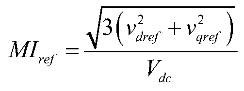 其中,V dc为母线电压;再将电机控制系统最大调制比MI max与期望的调制比MI ref作差得到ΔMI 0,最后经过低通滤波器得到调制比偏差ΔMI:所述电流特征点设定模块设定电机三相端部短路时的d轴母线电流i d_sc为:
 其中,为转子永磁体磁通,L d为d轴电感;
 所述电流补偿矢量幅值计算模块以调制比偏差计算模块的输出调制比偏差ΔMI为输入,进行如下比例积分调节,得到电流矢量补偿幅值|Δi|:
 其中,k p为比例积分控制器的比例系数,k i为比例积分控制器的积分系数;所述电流补偿矢量角度计算模块计算当前运行点(i dref,i qref)到(i d_sc,0)的电流补偿矢量角度θ:
 所述电流补偿矢量计算模块根据电流补偿矢量幅值计算模块输出的电流矢量补偿幅值|Δi|和电流补偿矢量角度计算输出的电流补偿矢量角度θ,计算dq轴补偿分量△i dref、△i dref如下:Δi qref=-|Δi|sinθΔi dref=|Δi|cosθ所述电流指令修正模块将电流补偿矢量计算模块的输出△i dref、△i dref与原始dq电流指令i dref、i dref进行叠加得到修正后的dq电流指令


Priority Applications (3)
| Application Number | Priority Date | Filing Date | Title |
|---|---|---|---|
| PCT/CN2020/100989 WO2022006803A1 (zh) | 2020-07-09 | 2020-07-09 | 一种电驱动系统永磁同步电机矢量弱磁控制系统 |
| JP2021556965A JP7313081B2 (ja) | 2020-07-09 | 2020-07-09 | 電気駆動システムにおける永久磁石同期モータベクトル弱め界磁制御システム |
| US17/348,772 US11502631B2 (en) | 2020-07-09 | 2021-06-16 | Vector flux weakening control system for permanent magnet synchronous motor of electric drive system |
Applications Claiming Priority (1)
| Application Number | Priority Date | Filing Date | Title |
|---|---|---|---|
| PCT/CN2020/100989 WO2022006803A1 (zh) | 2020-07-09 | 2020-07-09 | 一种电驱动系统永磁同步电机矢量弱磁控制系统 |
Related Child Applications (1)
| Application Number | Title | Priority Date | Filing Date |
|---|---|---|---|
| US17/348,772 Continuation US11502631B2 (en) | 2020-07-09 | 2021-06-16 | Vector flux weakening control system for permanent magnet synchronous motor of electric drive system |
Publications (1)
| Publication Number | Publication Date |
|---|---|
| WO2022006803A1 true WO2022006803A1 (zh) | 2022-01-13 |
Family
ID=79173124
Family Applications (1)
| Application Number | Title | Priority Date | Filing Date |
|---|---|---|---|
| PCT/CN2020/100989 Ceased WO2022006803A1 (zh) | 2020-07-09 | 2020-07-09 | 一种电驱动系统永磁同步电机矢量弱磁控制系统 |
Country Status (3)
| Country | Link |
|---|---|
| US (1) | US11502631B2 (zh) |
| JP (1) | JP7313081B2 (zh) |
| WO (1) | WO2022006803A1 (zh) |
Families Citing this family (2)
| Publication number | Priority date | Publication date | Assignee | Title |
|---|---|---|---|---|
| JP7590029B2 (ja) * | 2021-06-30 | 2024-11-26 | 浙江大学 | ベクトル角制御方法 |
| US12047022B2 (en) * | 2021-10-04 | 2024-07-23 | Borgwarner Inc. | Field weakening regulator for CVFR current regulator |
Citations (5)
| Publication number | Priority date | Publication date | Assignee | Title |
|---|---|---|---|---|
| US20050212471A1 (en) * | 2004-03-24 | 2005-09-29 | Patel Nitinkumar R | Current regulation for a field weakening motor control system and method |
| CN1797928A (zh) * | 2004-12-20 | 2006-07-05 | Lg电子株式会社 | 在弱磁区运行永磁同步发动机的导程角控制方法和装置 |
| CN107592047A (zh) * | 2017-09-18 | 2018-01-16 | 四川爱迪特斯科技有限公司 | 一种永磁同步电机自适应弱磁控制方法 |
| CN109150042A (zh) * | 2018-07-23 | 2019-01-04 | 同济大学 | 一种表面式永磁同步电机前馈解耦弱磁控制方法 |
| CN111277182A (zh) * | 2019-12-06 | 2020-06-12 | 浙江零跑科技有限公司 | 一种车用永磁同步电机深度弱磁系统及其控制方法 |
Family Cites Families (3)
| Publication number | Priority date | Publication date | Assignee | Title |
|---|---|---|---|---|
| JP4730658B2 (ja) | 2005-10-24 | 2011-07-20 | 株式会社安川電機 | 同期電動機制御装置 |
| EP2075906A4 (en) * | 2006-10-19 | 2013-09-11 | Mitsubishi Electric Corp | VECTOR CONTROLLER OF A PERMANENT MAGNET SYNCHRONOUS MOTOR |
| US8193747B2 (en) * | 2009-05-28 | 2012-06-05 | GM Global Technology Operations LLC | Methods, systems and apparatus for controlling operation of two alternating current (AC) machines |
-
2020
- 2020-07-09 JP JP2021556965A patent/JP7313081B2/ja active Active
- 2020-07-09 WO PCT/CN2020/100989 patent/WO2022006803A1/zh not_active Ceased
-
2021
- 2021-06-16 US US17/348,772 patent/US11502631B2/en active Active
Patent Citations (5)
| Publication number | Priority date | Publication date | Assignee | Title |
|---|---|---|---|---|
| US20050212471A1 (en) * | 2004-03-24 | 2005-09-29 | Patel Nitinkumar R | Current regulation for a field weakening motor control system and method |
| CN1797928A (zh) * | 2004-12-20 | 2006-07-05 | Lg电子株式会社 | 在弱磁区运行永磁同步发动机的导程角控制方法和装置 |
| CN107592047A (zh) * | 2017-09-18 | 2018-01-16 | 四川爱迪特斯科技有限公司 | 一种永磁同步电机自适应弱磁控制方法 |
| CN109150042A (zh) * | 2018-07-23 | 2019-01-04 | 同济大学 | 一种表面式永磁同步电机前馈解耦弱磁控制方法 |
| CN111277182A (zh) * | 2019-12-06 | 2020-06-12 | 浙江零跑科技有限公司 | 一种车用永磁同步电机深度弱磁系统及其控制方法 |
Also Published As
| Publication number | Publication date |
|---|---|
| JP7313081B2 (ja) | 2023-07-24 |
| US20220014132A1 (en) | 2022-01-13 |
| US11502631B2 (en) | 2022-11-15 |
| JP2022542529A (ja) | 2022-10-05 |
Similar Documents
| Publication | Publication Date | Title |
|---|---|---|
| CN111711394B (zh) | 一种电驱动系统永磁同步电机矢量弱磁控制系统 | |
| CN112671300B (zh) | 一种基于直流功率的车用永磁同步电机矢量控制方法 | |
| CN112688610B (zh) | 一种车用永磁同步电机矢量弱磁控制方法 | |
| CN107968611B (zh) | 同步电机控制电路及控制方法 | |
| RU2407140C1 (ru) | Векторный регулятор для синхронного электродвигателя с постоянными магнитами | |
| CN110635740A (zh) | 一种基于电压前馈补偿策略的永磁同步电机矢量控制方法 | |
| CN103997267A (zh) | 一种开绕组永磁同步电机的串联补偿直接转矩控制方法 | |
| CN112701969B (zh) | 一种同步磁阻电机最大转矩电流比在线寻优方法 | |
| CN106788078B (zh) | 一种避免永磁同步电机弱磁失控的方法 | |
| CN113328666B (zh) | 一种计及扭矩精度的车用永磁同步电机矢量弱磁控制系统 | |
| CN111277182A (zh) | 一种车用永磁同步电机深度弱磁系统及其控制方法 | |
| CN112671301B (zh) | 基于直流功率的车用永磁同步电机mtpa曲线搜索方法 | |
| Zhang et al. | Circular arc voltage trajectory method for smooth transition in induction motor field-weakening control | |
| US11502631B2 (en) | Vector flux weakening control system for permanent magnet synchronous motor of electric drive system | |
| CN113315434A (zh) | 一种基于机械功率预估的车用永磁同步电机矢量控制系统 | |
| CN109831138B (zh) | 永磁同步电机最大效率转矩比控制方法及控制器 | |
| CN110890854B (zh) | 同步电动机控制装置 | |
| CN105245135A (zh) | 一种永磁同步电机恒功率区运行的弱磁控制方法 | |
| Jiang et al. | An improved virtual constant signal injection MTPA control for PMa-SynRM drives | |
| Jing et al. | Voltage Angle Regulated Field Weakening Control Based on Overmodulation Strategy for PMa-SynRM Drives | |
| CN111146993B (zh) | 一种异步电机电压解耦补偿的矢量控制方法 | |
| CN115360950A (zh) | 一种基于负载特性的永磁同步电机扩速方法 | |
| CN115441780A (zh) | 一种基于负载特性的永磁同步电机电压反馈弱磁控制方法 | |
| CN113364378A (zh) | 一种计及定向偏差基于机械功率的电机矢量控制系统 | |
| CN116191951A (zh) | 一种基于矢量控制的异步电机弱磁控制方法 |
Legal Events
| Date | Code | Title | Description |
|---|---|---|---|
| ENP | Entry into the national phase |
Ref document number: 2021556965 Country of ref document: JP Kind code of ref document: A |
|
| 121 | Ep: the epo has been informed by wipo that ep was designated in this application |
Ref document number: 20944147 Country of ref document: EP Kind code of ref document: A1 |
|
| NENP | Non-entry into the national phase |
Ref country code: DE |
|
| 122 | Ep: pct application non-entry in european phase |
Ref document number: 20944147 Country of ref document: EP Kind code of ref document: A1 |