WO2022004774A1 - 表示システム及びロボットシステム - Google Patents
表示システム及びロボットシステム Download PDFInfo
- Publication number
- WO2022004774A1 WO2022004774A1 PCT/JP2021/024703 JP2021024703W WO2022004774A1 WO 2022004774 A1 WO2022004774 A1 WO 2022004774A1 JP 2021024703 W JP2021024703 W JP 2021024703W WO 2022004774 A1 WO2022004774 A1 WO 2022004774A1
- Authority
- WO
- WIPO (PCT)
- Prior art keywords
- virtual
- robot
- camera
- work
- image information
- Prior art date
- Legal status (The legal status is an assumption and is not a legal conclusion. Google has not performed a legal analysis and makes no representation as to the accuracy of the status listed.)
- Ceased
Links
Images

Classifications
-
- B—PERFORMING OPERATIONS; TRANSPORTING
- B25—HAND TOOLS; PORTABLE POWER-DRIVEN TOOLS; MANIPULATORS
- B25J—MANIPULATORS; CHAMBERS PROVIDED WITH MANIPULATION DEVICES
- B25J13/00—Controls for manipulators
- B25J13/02—Hand grip control means
Definitions
- This disclosure relates to display systems and robot systems.
- a display system that displays a three-dimensional image representing a robot work cell on various mobile terminals is known (see, for example, Patent Document 1).
- a display that generates robot work cell data including a three-dimensional robot model and a model of another structure of the work cell and displays a three-dimensional rendering of the generated three-dimensional robot model or the like. have.
- Patent Document 1 when a user (operator) operates a robot displayed on a display by using an operating means, the robot before the robot performs an operation. , Showing a collision object (eg, a safety wall) in the display. Then, when the physical robot collides with the colliding object by the user's operation, the collision is displayed on the display.
- a collision object eg, a safety wall
- the programmer needs to create 3D data such as a 3D robot model and an animated 3D robot model. Therefore, as the number of types of work to be worked on by the robot increases, the number of data to be created becomes enormous, and the data creation cost increases. In particular, when the amount of work is small, the ratio of the data creation cost to the production cost becomes large.
- the display system disclosed in Patent Document 1 still has room for improvement from the viewpoint of improving production efficiency.
- the present disclosure is intended to solve the above-mentioned problems, and to provide a display system and a robot system capable of improving production efficiency as compared with a conventional display system.
- the display system is a 3D model of a first workspace in the workspace based on a 3D camera arranged in the workspace and image information obtained by the 3D camera.
- the virtual image information obtained when the virtual camera, which is a virtual camera captures the 3D model from the virtual viewpoint, which is the position of the virtual camera, with the virtual line of sight, which is the direction of the virtual camera.
- a first control device to be formed, a first operation device for receiving an input of an operation instruction to the virtual camera, and a display device for displaying the virtual image information are provided, and the first control device includes the image information.
- the 3D model is formed in real time, the virtual viewpoint is moved or the virtual line of sight is changed so as to be linked to the operation amount of the operation instruction, and the virtual image information is displayed on the display device. ..
- the robot system includes the display system, a robot arranged in the work space and performing work on the work arranged in the first work space, and the robot. It includes a second operating device that receives input of an operation instruction to the robot, and a second control device that controls the operation of the robot based on the operation instruction received by the second operating device.
- the production efficiency can be improved as compared with the conventional display system.
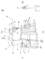
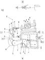
- FIG. 1 is a schematic diagram showing a schematic configuration of a display system and a robot system according to the first embodiment.
- FIG. 2 is a schematic diagram showing a schematic configuration of equipment arranged in the work space of the display system and the robot system shown in FIG.
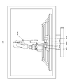
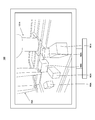
- FIG. 3 is a schematic diagram showing how a first example of virtual image information in the first workspace is displayed on the display device included in the display system and the robot system shown in FIG. 1.
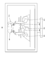
- FIG. 4 is a schematic diagram showing how a second example of virtual image information in the first workspace is displayed on the display device included in the display system and the robot system shown in FIG. 1.
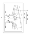
- FIG. 5 is a schematic diagram showing how a third example of virtual image information in the first workspace is displayed on the display device included in the display system and the robot system shown in FIG. 1.
- FIG. 1 is a schematic diagram showing a schematic configuration of a display system and a robot system according to the first embodiment.
- FIG. 2 is a schematic diagram showing a schematic configuration of equipment arranged in the work space of the display system
- FIG. 6 is a schematic diagram showing how a fourth example of virtual image information in the first workspace is displayed on the display device included in the display system and the robot system shown in FIG. 1.
- FIG. 7 is a schematic diagram showing a schematic configuration of the display system and the robot system according to the second embodiment.
- FIG. 1 is a schematic diagram showing a schematic configuration of a display system and a robot system according to the first embodiment.
- the display system 100 includes a 3D camera 102, a display device 103, a first operator 104, and a first control device 111.
- the robot system 200 according to the first embodiment includes a display system 100, a robot 101, a second controller 105, and a second control device 112.
- the robot 101, the 3D camera 102, and the second control device 112 are arranged in the work space 201, and the display device 103, the first operation device 104, the second operation device 105, and the first control device 111 are arranged in the operation space 202. Placed inside.
- the second control device 112 may be arranged in the operation space 202.
- the work space 201 is a space in which the robot 101 is installed, and includes at least a space within the operating range of the robot 101. Further, the operation space 202 is a space different from the work space 201, and is a space separated from the work space 201.
- the work space 201 and the operation space 202 may be separated by the partition wall member 210.
- a part of the partition wall member 210 may be a transparent member such as a glass plate so that the operator can visually recognize the inside of the work space 201 from the outside.
- FIG. 2 is a schematic diagram showing a schematic configuration of equipment arranged in the work space of the display system and the robot system shown in FIG. First, the equipment arranged in the work space 201 will be described with reference to FIG.
- the 3D camera 102 is arranged in the work space 201. Specifically, the 3D camera 102 is arranged at a position where the first work space 220 can be photographed. In the first embodiment, the 3D camera 102 is arranged in front of the robot 101 (work W1 to work W5).
- the first work space 220 refers to a space within the operating range of the robot 101.
- the 3D camera 102 outputs the image information obtained by photographing the inside of the work space 201 to the first control device 111.
- the 3D camera 102 may have a large angle of view from the viewpoint of widening the shooting range.
- the angle of view of the 3D camera 102 may be, for example, 100 ° or more and 125 ° or less.
- the angle of view of the 3D camera 102 may be, for example, 120 °.
- the configuration of the first control device 111 will be described later.
- the robot 101 is arranged in the work space 201, and works on the work W1 to the work W5 arranged in the first work space 220.
- the robot 101 is placed on the moving body 60.
- the moving body 60 is arranged on the rail members 301A and 301B extending in the left-right direction, and can move in the left-right direction by an appropriate actuator.
- the robot 101 supports a plurality of links (here, the first link 11a to the sixth link 11f) and a plurality of joints (here, the first joint JT1 to the sixth joint JT6).
- It is a vertical articulated robot provided with a base 15.
- a vertical articulated robot is adopted as the robot 101, but the robot is not limited to this, and a horizontal articulated robot may be adopted.
- the base 15 and the base end portion of the first link 11a are rotatably connected around an axis extending in the vertical direction.
- the tip end portion of the first link 11a and the base end portion of the second link 11b are rotatably connected around an axis extending in the horizontal direction.
- the tip end portion of the second link 11b and the base end portion of the third link 11c are rotatably connected around an axis extending in the horizontal direction.
- the tip end portion of the 3rd link 11c and the base end portion of the 4th link 11d are rotatably connected around an axis extending in the longitudinal direction of the 4th link 11d.
- the tip end portion of the fourth link 11d and the base end portion of the fifth link 11e are rotatably connected around an axis orthogonal to the longitudinal direction of the fourth link 11d.
- the tip end portion of the fifth link 11e and the base end portion of the sixth link 11f are rotatably connected to each other.
- a mechanical interface 12 is provided at the tip of the sixth link 11f.
- a hand 20 is detachably attached to the mechanical interface 12.
- the hand 20 has a pair of finger members 30A and 30B, can hold the works W1 to W5, and can release the held works W1 to W5.
- each of the first joint JT1 to the sixth joint JT6 is provided with a drive motor as an example of an actuator that relatively rotates two members to which each joint is connected.
- the drive motor may be, for example, a servomotor controlled by a second control device 112.
- the first joint JT1 to the sixth joint JT6 are provided with a rotation sensor for detecting the rotation position of the drive motor and a current sensor for detecting the current for controlling the rotation of the drive motor, respectively.
- the rotation sensor may be, for example, an encoder.
- the second control device 112 controls the operation of the robot 101 based on the operation instruction received by the second operation device 105.
- the second control device 112 includes an arithmetic processor such as a microprocessor and a CPU, and a storage device such as a ROM and a RAM.
- the storage device stores information such as basic programs and various fixed data.
- the arithmetic processor executes various operations of the robot 101 by reading and executing software such as a basic program stored in the storage. Further, the second control device 112 operates the robot 101 based on the operation command information for the robot 101 input from the second operation device 105.
- the second control device 112 may be a single control device for centralized control, or may be a plurality of control devices for distributed control in cooperation with each other. Further, the second control device 112 may be a microcomputer, an MPU, a PLC (Programmable Logic Controller), a logic circuit, or the like.
- the display device 103 displays virtual image information described later. Specifically, the display device 103 displays 3D models of devices arranged in the first work space 220 such as the works W1 to W5 and the robot 101 output from the first control device 111. The display device 103 may display virtual image information described later such as the works W1 to W5 and the robot 101 obtained by the 3D camera 102.
- the display device 103 may be, for example, a stationary display that is used by being stationary on a desk, floor, or the like, or may be a head-mounted display or glasses that the operator wears and uses.
- the first operation device 104 receives an input of an operation instruction to the virtual camera.
- the virtual camera is a virtual camera different from the 3D camera 102 actually arranged in the work space 201, and the virtual viewpoint and the virtual line of sight related to the formation of the virtual image information described later are conveniently used. It is a conceptual module for explanation.
- the virtual viewpoint is the position of the virtual camera, and the virtual line of sight is the direction of the virtual camera.
- an operation signal is input from the first operating device 104 to the first control device 111.
- the first actuator 104 for example, a known actuator such as a joystick, a keyboard, a numeric keypad, or a mouse can be used.
- the second actuator 105 receives an input of an operation instruction to the robot 101.
- a known actuator such as a joystick, a keyboard, a numeric keypad, a mouse, or a teach pendant can be used.
- the second operation device 105 may be provided with a device for transmitting force sense information or voice information detected by the force sense sensor provided in the hand 20 of the robot 101 to the operator.
- the device include a vibration motor, a speaker, a mechanism for expanding and contracting a housing constituting a grip portion, and the like.
- the second actuator 105 may be portable and portable by the operator. Further, the robot 101 and the second actuator 105 may be of a master-slave system.
- the first control device 111 includes an arithmetic processor such as a microprocessor and a CPU, and a storage device such as a ROM and a RAM.
- the storage device stores information such as basic programs and various fixed data.
- the arithmetic processor executes various operations of the display system 100 by reading and executing software such as a basic program stored in the storage.
- the first control device 111 forms a 3D model of the first work space 220 in the work space 201 based on the image information obtained by the 3D camera 102, and the virtual camera, which is a conceptual module, is the position of the virtual camera. From the virtual viewpoint, which is the direction of the virtual camera, the virtual image information obtained when the 3D model is photographed is further formed.
- the first control device 111 forms the 3D model in real time based on the image information obtained by the 3D camera 102, and the virtual one is linked to the operation amount of the operation instruction received by the first operation device 104.
- the viewpoint is moved or the virtual line of sight is changed so that the virtual image information is displayed on the display device 103.
- the fact that the first control device 111 forms the 3D model in real time means that when the first control device 111 receives the 3D model formation request, the 3D model formation process is immediately executed. It should be noted that the first control device 111 may perform the process from receiving the 3D model formation request to displaying the virtual image information on the display device 103 in real time.
- the permissible range of the time lag that occurs from the reception of the 3D model formation request by the first control device 111 to the display of the virtual image information on the display device 103 may be predetermined. Then, when a delay larger than this allowable range occurs, the first control device 111 may display the error information on the display device 111.
- the operator can operate the first operating device 104 to move the virtual viewpoint of the 3D model displayed on the display device 103, or change the virtual line of sight. Further, since it is not necessary for the programmer to create a 3D model of the work, the cost for creating the data can be reduced. Therefore, the production efficiency can be improved as compared with the display system disclosed in Patent Document 1.
- FIG. 3 is a schematic diagram showing how the first example of virtual image information in the first workspace is displayed on the display device included in the display system and the robot system shown in FIG.
- the first control device 111 is a 3D robot 101A which is a 3D model of the robot 101 as shown in FIG.
- the 3D work W1A to 3D work W5A which are 3D models of the work W1 to the work W5, are displayed on the display device 103.
- FIG. 4 is a schematic diagram showing how the display device included in the display system and the robot system shown in FIG. 1 displays a second example of virtual image information in the first workspace.
- the first control device 111 is a 3D model of the hand 20 as shown in FIG.
- the 3D hand 20A, the 3D work W1A to the 3D work W5A, and the enlarged 3D model are displayed on the display device 103.
- the virtual image information displayed on the display device 103 as shown in FIG. 4 includes the work W1 to the work W5 (3D work W1A to 3D work W1A to). Positional relationship (sense of distance, depth) of each of 3D work W5A), positional relationship (sense of distance, depth) between work W1 to work W5 (3D work W1A to 3D work W5A) and hand 20 (3D hand 20A). Feeling) may be difficult to grasp.
- FIG. 5 is a schematic diagram showing how a third example of virtual image information in the first workspace is displayed on the display device included in the display system and the robot system shown in FIG.
- the operator operates the first controller 104 so as to track the virtual camera in the 3D model to the right side of the 3D robot 101A, as shown in FIG.
- the first control device 111 causes the display device 103 to display such virtual image information.
- the operation command information input from the second actuator 105 to the second control device 112 is first. It may be acquired by the control device 111. Then, the first control device 111 may operate the 3D robot 101A (move the 3D robot 101A) based on the acquired operation command information.
- FIG. 6 is a schematic diagram showing how the display device included in the display system and the robot system shown in FIG. 1 displays a fourth example of virtual image information in the first workspace.
- the first control device 111 displays virtual image information as shown in FIG. Display on 103.
- the operator can obtain the positional relationship (sense of distance and depth) of the works W1 to W5 (3D work W1A to 3D work W5A), the work W1 to the work W5 (3D work W1A to 3D work W5A), and the work W1 to the work W5 (3D work W1A to 3D work W5A).
- the positional relationship (sense of distance, sense of depth) with the hand 20 (3D hand 20A) can be easily grasped.
- the operator can easily remotely control the robot 101 by the second operating device 105 while viewing the virtual image information of the 3D model displayed on the display device 103.
- the operator inputs an operation instruction to the first operator 104 to track the virtual line of sight to the right side of the 3D robot 101A as shown in FIG.
- the operator can easily determine the positional relationship between the 3D hand 20A and the 3D work W1A in the depth direction.
- the operator can input the operation instruction to the second actuator 105 and make the robot 101 surely hold the work W1.
- FIG. 7 is a schematic diagram showing a schematic configuration of the display system and the robot system according to the second embodiment.
- the display system 100 and the robot system 200 according to the second embodiment have the same basic configurations as the display system 100 and the robot system 200 according to the first embodiment, but the 3D camera 102 has the same basic configuration. The difference is that multiple units are installed.
- the three 3D cameras 102A to 102C are arranged so as to shoot the first work space 220 from different directions.
- the first control device 111 forms a 3D model of various devices such as the work W1 to the work W5 and the robot 101 arranged in the first work space 220 in real time based on the image information obtained by the 3D camera 102A. ..
- the first control device 111 creates 3D models of various devices such as the work W1 to the work W5 and the robot 101 arranged in the first work space 220 in real time based on the image information obtained by the 3D cameras 102B and 102C. Formed by.
- the first control device 111 synthesizes the formed three 3D models based on the formed three 3D models, and various types such as the work W1 to the work W5 and the robot 101 arranged in the first work space 220. Reshape the 3D model of the device.
- the area (range) that can be photographed can be expanded as compared with the case where the first work space 220 is photographed from the front of the robot 101 with one 3D camera 102. Therefore, it is possible to more accurately form 3D models of various devices such as the works W1 to W5 and the robot 101 arranged in the first work space 220.
- the 3D model of the first workspace 220 can be formed more accurately, so that the operator can more accurately and faster.
- the work W1 to the work W5 can be held and conveyed by the hand 20 of the robot 101.
- the robot 101 adopts a mode in which the work W1 to the work W5 are held and conveyed, but the work executed by the robot 101 is limited to this. Not done.
- the robot 101 can perform various operations such as painting on a work, polishing the work, cutting the work, and welding the work.
- the display system is a 3D model of a first workspace in the workspace based on a 3D camera arranged in the workspace and image information obtained by the 3D camera.
- the virtual image information obtained when the virtual camera, which is a virtual camera captures the 3D model from the virtual viewpoint, which is the position of the virtual camera, with the virtual line of sight, which is the direction of the virtual camera.
- a first control device to be formed, a first operation device for receiving an input of an operation instruction to the virtual camera, and a display device for displaying the virtual image information are provided, and the first control device includes the image information.
- the 3D model is formed in real time, the virtual viewpoint is moved or the virtual line of sight is changed so as to be linked to the operation amount of the operation instruction, and the virtual image information is displayed on the display device. ..
- a plurality of the 3D cameras may be arranged in the work space.
- the plurality of 3D cameras may be arranged so as to photograph the first work space from different directions.
- the first control device may form the 3D model for each of the plurality of the 3D cameras, and may reshape the 3D model captured by the virtual camera based on the formed plurality of the 3D models.
- the robot system works on a display system having any of the above configurations and a work arranged in the work space and arranged in the first work space.
- a robot that performs the operation, a second operating device that receives an input of an operation instruction to the robot, and a second control device that controls the operation of the robot based on the operation instruction received by the second operating device. ..
- the production efficiency can be improved as compared with the conventional display system, which is useful in the field of robots.
Landscapes
- Engineering & Computer Science (AREA)
- Robotics (AREA)
- Mechanical Engineering (AREA)
- Manipulator (AREA)
Abstract
本開示に係る表示システムは、作業空間内に配置される3Dカメラと、前記3Dカメラにより得られる画像情報に基づき、前記作業空間内の第1作業空間の3Dモデルを形成し、仮想的なカメラである仮想カメラが、前記仮想カメラの位置である仮想視点から、前記仮想カメラの向きである仮想視線で、前記3Dモデルを撮影したときに得られる仮想画像情報をさらに形成する第1制御装置と、前記仮想カメラへの操作指示の入力を受け付ける第1操作器と、前記仮想画像情報を表示する表示装置と、を備え、前記第1制御装置は、前記画像情報に基づき、前記3Dモデルをリアルタイムで形成し、前記操作指示の操作量に連動するように、前記仮想視点を移動し、又は前記仮想視線を変更し、前記仮想画像情報を前記表示装置に表示させる。
Description
本開示は、表示システム及びロボットシステムに関する。
種々の携帯端末に、ロボットのワークセルを表す3次元画像を表示する表示システムが知られている(例えば、特許文献1参照)。特許文献1に開示されている表示システムでは、3次元ロボットモデル及びワークセルの他の構造のモデルを含むロボットワークセルデータを生成し、生成した3次元ロボットモデル等の3次元レンダリングを表示するディスプレイを有している。
また、特許文献1に開示されている、表示システムでは、ユーザ(操作者)が、操作手段を用いて、ディスプレイに表示されているロボットを操作するときに、当該ロボットが動作を実行する前に、ディスプレイ内に衝突物(例えば、セーフティウォール)を示している。そして、ユーザの操作によって、物理的なロボットと衝突物とが衝突する場合には、その衝突をディスプレイに表示するように構成されている。
しかしながら、上記特許文献1に開示されている表示システムでは、プログラマが、3次元ロボットモデル、アニメ化された3次元ロボットモデル等の3次元データを作成する必要がある。このため、ロボットの作業対象となるワークの種類が多くなると、その作成するデータ数が膨大となり、データの作成費用が増加する。特に、ワークが少量である場合には、生産コストにおけるデータの作成費用の割合が大きくなる。
したがって、上記特許文献1に開示されている表示システムには、生産効率の向上の観点から未だ改善の余地があった。
本開示は、上記課題を解決するもので、従来の表示システムに比して、生産効率を向上させることができる、表示システム及びロボットシステムを提供することを目的とする。
上記課題を解決するために、本開示に係る表示システムは、作業空間内に配置される3Dカメラと、前記3Dカメラにより得られる画像情報に基づき、前記作業空間内の第1作業空間の3Dモデルを形成し、仮想的なカメラである仮想カメラが、前記仮想カメラの位置である仮想視点から、前記仮想カメラの向きである仮想視線で、前記3Dモデルを撮影したときに得られる仮想画像情報をさらに形成する第1制御装置と、前記仮想カメラへの操作指示の入力を受け付ける第1操作器と、前記仮想画像情報を表示する表示装置と、を備え、前記第1制御装置は、前記画像情報に基づき、前記3Dモデルをリアルタイムで形成し、前記操作指示の操作量に連動するように、前記仮想視点を移動し、又は前記仮想視線を変更し、前記仮想画像情報を前記表示装置に表示させる。
これにより、プログラマにより、ワークの3Dモデルを作成する必要がないため、データ作成にかかる費用を低減することができる。このため、上記特許文献1に開示されている表示システムに比して、生産効率を向上させることができる。
上記課題を解決するために、本開示に係るロボットシステムは、前記表示システムと、前記作業空間内に配置され、前記第1作業空間内に配置されるワークに対して作業を行うロボットと、前記ロボットへの操作指示の入力を受け付ける第2操作器と、前記第2操作器により受け付けた前記操作指示に基づき、前記ロボットの動作を制御する第2制御装置と、を備える。
これにより、プログラマにより、ワークの3Dモデルを作成する必要がないため、データ作成にかかる費用を低減することができる。このため、上記特許文献1に開示されている表示システムに比して、生産効率を向上させることができる。
本開示の上記目的、他の目的、特徴、及び利点は、添付図面参照の下、以下の好適な実施形態の詳細な説明から明らかにされる。
本開示の表示システム及びロボットシステムによれば、従来の表示システムに比して、生産効率を向上させることができる。
以下、本開示の実施の形態を、図面を参照しながら説明する。なお、全ての図面において、同一又は相当部分には同一符号を付し、重複する説明は省略する。また、全ての図面において、本開示を説明するための構成要素を抜粋して図示しており、その他の構成要素については図示を省略している場合がある。さらに、本開示は以下の実施の形態に限定されない。
(実施の形態1)
以下、本実施の形態1に係る表示システム及びロボットシステムの一例について、図1~図5を参照しながら説明する。
以下、本実施の形態1に係る表示システム及びロボットシステムの一例について、図1~図5を参照しながら説明する。
[表示システム及びロボットシステムの構成及び作用効果]
図1は、本実施の形態1に係る表示システム及びロボットシステムの概略構成を示す模式図である。
図1は、本実施の形態1に係る表示システム及びロボットシステムの概略構成を示す模式図である。
図1に示すように、本実施の形態1に係る表示システム100は、3Dカメラ102、表示装置103、第1操作器104、及び第1制御装置111を備えている。また、本実施の形態1に係るロボットシステム200は、表示システム100、ロボット101、第2操作器105、及び第2制御装置112を備える。
ロボット101、3Dカメラ102、及び第2制御装置112は、作業空間201内に配置され、表示装置103、第1操作器104、第2操作器105、及び第1制御装置111は、操作空間202内に配置される。なお、第2制御装置112は、操作空間202内に配置されてもよい。
作業空間201は、ロボット101が設置される空間であり、少なくともロボット101の動作範囲内の空間を含む。また、操作空間202は、作業空間201とは異なる空間であり、作業空間201から切り離された空間である。
なお、作業空間201と操作空間202は、隔壁部材210により、隔離されてもよい。隔壁部材210は、その一部が、ガラス板等の透明な部材であり、操作者が外部から作業空間201内を視認可能であってもよい。
図2は、図1に示す表示システム及びロボットシステムの作業空間内に配置されている機器の概略構成を示す模式図である。まず、図2を参照しながら、作業空間201内に配置されている機器について説明する。
図2に示すように、3Dカメラ102は、作業空間201内に配置される。具体的には、3Dカメラ102は、第1作業空間220を撮影できる位置に配置される。3Dカメラ102は、本実施の形態1においては、ロボット101(ワークW1~ワークW5)の前方に配置される。なお、第1作業空間220は、ロボット101の動作範囲内の空間をいう。
また、3Dカメラ102は、作業空間201内を撮影することにより得られた画像情報を第1制御装置111に出力する。3Dカメラ102は、撮影範囲を広げる観点から、画角が大きくてもよい。3Dカメラ102の画角は、例えば、100°以上125°以下であってもよい。3Dカメラ102の画角は、例えば、120°であってもよい。なお、第1制御装置111の構成については、後述する。
ロボット101は、作業空間201内に配置され、第1作業空間220内に配置されるワークW1~ワークW5に対して作業を行う。ロボット101は、移動体60上に載置される。移動体60は、左右方向に延びるレール部材301A、301B上に配置され、適宜なアクチュエータにより、左右方向に移動可能である。
また、ロボット101は、複数のリンク(ここでは、第1リンク11a~第6リンク11f)の連接体と、複数の関節(ここでは、第1関節JT1~第6関節JT6)と、これらを支持する基台15と、を備える、垂直多関節ロボットである。なお、本実施の形態1においては、ロボット101として、垂直多関節型ロボットを採用したが、これに限定されず、水平多関節型ロボットを採用してもよい。
第1関節JT1では、基台15と、第1リンク11aの基端部とが、鉛直方向に延びる軸回りに回転可能に連結される。第2関節JT2では、第1リンク11aの先端部と、第2リンク11bの基端部とが、水平方向に延びる軸回りに回転可能に連結される。第3関節JT3では、第2リンク11bの先端部と、第3リンク11cの基端部とが、水平方向に延びる軸回りに回転可能に連結される。
また、第4関節JT4では、第3リンク11cの先端部と、第4リンク11dの基端部とが、第4リンク11dの長手方向に延びる軸回りに回転可能に連結される。第5関節JT5では、第4リンク11dの先端部と、第5リンク11eの基端部とが、第4リンク11dの長手方向と直交する軸回りに回転可能に連結される。第6関節JT6では、第5リンク11eの先端部と第6リンク11fの基端部とが、捻れ回転可能に連結される。
そして、第6リンク11fの先端部には、メカニカルインターフェース12が設けられる。このメカニカルインターフェース12には、ハンド20が着脱可能に装着される。ハンド20は、一対の指部材30A、30Bを有し、ワークW1~ワークW5を保持可能であり、保持したワークW1~ワークW5を解放可能である。
また、第1関節JT1~第6関節JT6には、それぞれ、各関節が連結する2つの部材を相対的に回転させるアクチュエータの一例としての駆動モータが設けられる。駆動モータは、例えば、第2制御装置112によってサーボ制御されるサーボモータであってもよい。また、第1関節JT1~第6関節JT6には、それぞれ、駆動モータの回転位置を検出する回転センサと、駆動モータの回転を制御する電流を検出する電流センサと、が設けられる。回転センサは、例えば、エンコーダであってもよい。
第2制御装置112は、第2操作器105により受け付けた前記操作指示に基づき、ロボット101の動作を制御する。第2制御装置112は、マイクロプロセッサ、CPU等の演算処理器と、ROM、RAM等の記憶器と、を備える。記憶器は、基本プログラム、各種固定データ等の情報を記憶する。演算処理器は、記憶器に記憶された基本プログラム等のソフトウェアを読み出して実行することにより、ロボット101の各種の動作を実行する。また、第2制御装置112は、第2操作器105から入力されたロボット101に対する操作指令情報に基づいて、ロボット101を動作させる。
なお、第2制御装置112は、集中制御する単独の制御装置であってもよいし、互いに協働して分散制御する複数の制御装置であってもよい。また、第2制御装置112は、マイクロコンピュータであってもよく、MPU、PLC(Programmable Logic Controller)、論理回路等であってもよい。
次に、図1を参照しながら、操作空間202内に配置されている機器について説明する。
表示装置103は、後述する仮想画像情報を表示する。具体的には、表示装置103は、第1制御装置111から出力されたワークW1~W5及びロボット101等の第1作業空間220内に配置されている機器の3Dモデルを表示する。なお、表示装置103は、3Dカメラ102により得られるワークW1~W5及びロボット101等の後述する仮想画像情報を表示してもよい。
表示装置103は、例えば、机、床等に据え置いて使用する、据え置き型のディスプレイであってもよいし、操作者が身に着けて使用するヘッドマウントディスプレイ又はメガネであってもよい。
第1操作器104は、仮想カメラへの操作指示の入力を受け付ける。ここで、仮想カメラとは、作業空間201内に実際に配置される3Dカメラ102とは異なる仮想的なカメラであって、後述する仮想画像情報の形成に係る仮想視点および仮想視線を便宜的に説明するための概念的なモジュールのことである。前記仮想視点とは、前記仮想カメラの位置のことであり、前記仮想視線とは、前記仮想カメラの向きのことである。
具体的には、第1操作器104を操作者が操作することにより、第1操作器104から操作信号が第1制御装置111に入力される。第1操作器104としては、例えば、ジョイスティック、キーボード、テンキー、マウス等の公知の操作器を用いることができる。
第2操作器105は、ロボット101への操作指示の入力を受け付ける。第2操作器105としては、例えば、ジョイスティック、キーボード、テンキー、マウス、ティーチペンダント等の公知の操作器を用いることができる。
また、第2操作器105には、ロボット101のハンド20に設けられた力覚センサが検知した力覚情報、又は音声情報を操作者に伝達する機器を配置してもよい。当該機器としては、例えば、振動モータ、スピーカー、把持部を構成する筐体を伸縮させる機構等が挙げられる。
なお、第2操作器105は、操作者が携帯して、持ち運び可能であってもよい。また、ロボット101と第2操作器105は、マスタースレーブ方式であってもよい。
第1制御装置111は、マイクロプロセッサ、CPU等の演算処理器と、ROM、RAM等の記憶器と、を備える。記憶器は、基本プログラム、各種固定データ等の情報を記憶する。演算処理器は、記憶器に記憶された基本プログラム等のソフトウェアを読み出して実行することにより、表示システム100の各種動作を実行する。
第1制御装置111は、3Dカメラ102により得られる画像情報に基づき、作業空間201内の第1作業空間220の3Dモデルを形成し、概念的なモジュールである仮想カメラが、前記仮想カメラの位置である仮想視点から、前記仮想カメラの向きである仮想視線で、前記3Dモデルを撮影したときに得られる仮想画像情報をさらに形成する。
そして、第1制御装置111は、3Dカメラ102により得られる画像情報に基づき、前記3Dモデルをリアルタイムで形成し、第1操作器104により受け付けた操作指示の操作量に連動するように、前記仮想視点を移動し、又は前記仮想視線を変更し、前記仮想画像情報を表示装置103に表示させる。ここで、第1制御装置111が3Dモデルをリアルタイムに形成するとは、第1制御装置111が3Dモデルの形成要求を受信したとき、即座に3Dモデルの形成処理を実行することをいう。なお、第1制御装置111が、3Dモデルの形成要求を受信してから、前記仮想画像情報を表示装置103に表示させるまでをリアルタイムで行ってもよい。また、第1制御装置111が、3Dモデルの形成要求を受信してから、前記仮想画像情報を表示装置103に表示させるまでに生じるタイムラグの許容範囲を予め定めておいてもよい。そして、この許容範囲よりも大きな遅延が生じたとき、第1制御装置111は、表示装置111にエラー情報を表示させてもよい。
上記構成により、操作者は、第1操作器104を操作し、表示装置103に表示されている3Dモデルの仮想視点を移動させ、または仮想視線を変更することができる。また、プログラマにより、ワークの3Dモデルを作成する必要がないため、データ作成にかかる費用を低減することができる。このため、上記特許文献1に開示されている表示システムに比して、生産効率を向上させることができる。
図3は、図1に示す表示システム及びロボットシステムが備える表示装置に、第1作業空間の仮想画像情報の第1例が表示されている様子を示す模式図である。例えば、第1制御装置111は、作業空間201内の3Dカメラ102の位置を3Dモデル内の仮想カメラの位置とした場合に、図3に示すように、ロボット101の3Dモデルである3Dロボット101A、及びワークW1~ワークW5の3Dモデルである3DワークW1A~3DワークW5Aを、表示装置103に表示させる。
図4は、図1に示す表示システム及びロボットシステムが備える表示装置に、第1作業空間の仮想画像情報の第2例が表示されている様子を示す模式図である。操作者が、3Dモデル内の仮想カメラをズームアップするように、第1操作器104を操作した場合には、第1制御装置111は、図4に示すように、ハンド20の3Dモデルである3Dハンド20A、3DワークW1A~3DワークW5Aを拡大した3Dモデルを表示装置103に表示させる。
また、図1及び図2に示すワークW5をロボット101に保持させる場合には、図4に示すような、表示装置103に表示される仮想画像情報では、ワークW1~ワークW5(3DワークW1A~3DワークW5A)のそれぞれの位置関係(距離感、奥行感)、ワークW1~ワークW5(3DワークW1A~3DワークW5A)と、ハンド20(3Dハンド20A)と、の位置関係(距離感、奥行感)がつかみにくい場合がある。
図5は、図1に示す表示システム及びロボットシステムが備える表示装置に、第1作業空間の仮想画像情報の第3例が表示されている様子を示す模式図である。上記のように位置関係がつかみにくい場合には、操作者が、3Dモデル内の仮想カメラを3Dロボット101Aの右側へトラックさせるように、第1操作器104を操作させることで、図5に示すような仮想画像情報を第1制御装置111が表示装置103に表示させる。
また、このとき、操作者が、第2操作器105を操作して、ロボット101を動作させた場合には、第2操作器105から第2制御装置112に入力された操作指令情報を第1制御装置111が取得してもよい。そして、第1制御装置111は、取得した操作指令情報を基に、3Dロボット101Aを動作(3Dロボット101Aを移動)させてもよい。
図6は、図1に示す表示システム及びロボットシステムが備える表示装置に、第1作業空間の仮想画像情報の第4例が表示されている様子を示す模式図である。操作者が、3Dモデル内の仮想カメラを3Dロボット101Aの左側へトラックさせるように、第1操作器104を操作させると、図6に示すような仮想画像情報を第1制御装置111が表示装置103に表示させる。
これにより、操作者は、ワークW1~ワークW5(3DワークW1A~3DワークW5A)のそれぞれの位置関係(距離感、奥行感)、ワークW1~ワークW5(3DワークW1A~3DワークW5A)と、ハンド20(3Dハンド20A)と、の位置関係(距離感、奥行感)を容易に把握することができる。
このため、操作者は、表示装置103に表示されている3Dモデルの仮想画像情報を見ながら、第2操作器105によるロボット101の遠隔操作を容易に実行することができる。
例えば、ロボット101によりワークW1を保持させる場合、図4で表示装置103に表示されている仮想画像では、奥行き方向に関して3Dハンド20Aと3DワークW1Aとの位置関係を操作者が判断しにくい。そこで、操作者は、第1操作器104に操作指示を入力して、図5に示すように仮想視線を3Dロボット101Aの右側へトラックさせる。これにより、奥行き方向に関して3Dハンド20Aと3DワークW1Aとの位置関係を操作者が容易に判断できる。その結果、操作者は、第2操作器105に操作指示を入力して、ロボット101にワークW1を確実に保持させることができる。
(実施の形態2)
以下、本実施の形態2に係る表示システム及びロボットシステムの一例について、図7を参照しながら説明する。
以下、本実施の形態2に係る表示システム及びロボットシステムの一例について、図7を参照しながら説明する。
[表示システム及びロボットシステムの構成]
図7は、本実施の形態2に係る表示システム及びロボットシステムの概略構成を示す模式図である。図7に示すように、本実施の形態2に係る表示システム100及びロボットシステム200は、実施の形態1に係る表示システム100及びロボットシステム200と基本的構成は同じであるが、3Dカメラ102が複数台、設置されている点が異なる。
図7は、本実施の形態2に係る表示システム及びロボットシステムの概略構成を示す模式図である。図7に示すように、本実施の形態2に係る表示システム100及びロボットシステム200は、実施の形態1に係る表示システム100及びロボットシステム200と基本的構成は同じであるが、3Dカメラ102が複数台、設置されている点が異なる。
具体的には、3台の3Dカメラ102A~102Cが、それぞれ、第1作業空間220を互いに異なる方向から撮影するように配置される。
また、第1制御装置111は、3Dカメラ102Aにより得られる画像情報に基づき、第1作業空間220内に配置されるワークW1~ワークW5、ロボット101等の各種機器の3Dモデルをリアルタイムで形成する。同様に、第1制御装置111は、3Dカメラ102B、102Cにより得られる画像情報に基づき、第1作業空間220内に配置されるワークW1~ワークW5、ロボット101等の各種機器の3Dモデルをリアルタイムで形成する。
第1制御装置111は、形成した3つの3Dモデルに基づき、例えば、形成した3つの3Dモデルを合成して、第1作業空間220内に配置されるワークW1~ワークW5、ロボット101等の各種機器の3Dモデルを再形成する。
これにより、1台の3Dカメラ102でロボット101の正面から第1作業空間220を撮影した場合に比して、撮影できる領域(範囲)を広げることができる。このため、第1作業空間220内に配置されるワークW1~ワークW5、ロボット101等の各種機器の3Dモデルをより正確に形成することができる。
したがって、本実施の形態2に係る表示システム100及びロボットシステム200では、第1作業空間220の3Dモデルをより正確に形成することができるため、操作者は、より正確に、かつ、より早く、ロボット101のハンド20でワークW1~ワークW5を保持、搬送する作業を実行することができる。
また、上記構成を備える、本実施の形態2に係る表示システム100及びロボットシステム200であっても、実施の形態1に係る表示システム100及びロボットシステム200と同様の作用効果を奏する。
なお、本実施の形態1及び2に係るロボットシステム200では、ロボット101がワークW1~ワークW5を保持、搬送する作業を実行する形態を採用したが、ロボット101が実行する作業は、これに限定されない。ロボット101は、例えば、ワークに塗装する作業、ワークを研磨する作業、ワークを切削する作業、ワークを溶接する作業等、種々の作業を実行することができる。
上記説明から、当業者にとっては、本発明の多くの改良又は他の実施形態が明らかである。従って、上記説明は、例示としてのみ解釈されるべきであり、本発明を実行する最良の態様を当業者に教示する目的で提供されたものである。本発明を逸脱することなく、その構造及び/又は機能の詳細を実質的に変更できる。
[まとめ]
上記課題を解決するために、本開示に係る表示システムは、作業空間内に配置される3Dカメラと、前記3Dカメラにより得られる画像情報に基づき、前記作業空間内の第1作業空間の3Dモデルを形成し、仮想的なカメラである仮想カメラが、前記仮想カメラの位置である仮想視点から、前記仮想カメラの向きである仮想視線で、前記3Dモデルを撮影したときに得られる仮想画像情報をさらに形成する第1制御装置と、前記仮想カメラへの操作指示の入力を受け付ける第1操作器と、前記仮想画像情報を表示する表示装置と、を備え、前記第1制御装置は、前記画像情報に基づき、前記3Dモデルをリアルタイムで形成し、前記操作指示の操作量に連動するように、前記仮想視点を移動し、又は前記仮想視線を変更し、前記仮想画像情報を前記表示装置に表示させる。
上記課題を解決するために、本開示に係る表示システムは、作業空間内に配置される3Dカメラと、前記3Dカメラにより得られる画像情報に基づき、前記作業空間内の第1作業空間の3Dモデルを形成し、仮想的なカメラである仮想カメラが、前記仮想カメラの位置である仮想視点から、前記仮想カメラの向きである仮想視線で、前記3Dモデルを撮影したときに得られる仮想画像情報をさらに形成する第1制御装置と、前記仮想カメラへの操作指示の入力を受け付ける第1操作器と、前記仮想画像情報を表示する表示装置と、を備え、前記第1制御装置は、前記画像情報に基づき、前記3Dモデルをリアルタイムで形成し、前記操作指示の操作量に連動するように、前記仮想視点を移動し、又は前記仮想視線を変更し、前記仮想画像情報を前記表示装置に表示させる。
これにより、プログラマにより、ワークの3Dモデルを作成する必要がないため、データ作成にかかる費用を低減することができる。このため、従来の表示システムに比して、生産効率を向上させることができる。
例えば、複数の前記3Dカメラが、前記作業空間内に配置されてもよい。
例えば、複数の前記3Dカメラは、それぞれ、前記第1作業空間を互いに異なる方向から撮影するように配置されてもよい。
前記第1制御装置は、複数の前記3Dカメラごとに前記3Dモデルを形成し、形成した複数の前記3Dモデルに基づき、前記仮想カメラにより撮影される前記3Dモデルを再形成してもよい。
これにより、第1作業空間の3Dモデルをより正確に形成することができる。
上記課題を解決するために、本開示に係るロボットシステムは、上記構成のいずれかを備える表示システムと、前記作業空間内に配置され、前記第1作業空間内に配置されるワークに対して作業を行うロボットと、前記ロボットへの操作指示の入力を受け付ける第2操作器と、前記第2操作器により受け付けた前記操作指示に基づき、前記ロボットの動作を制御する第2制御装置と、を備える。
これにより、プログラマにより、ワークの3Dモデルを作成する必要がないため、データ作成にかかる費用を低減することができる。このため、従来の表示システムに比して、生産効率を向上させることができる。
本開示の表示システム及びロボットシステムによれば、従来の表示システムに比して、生産効率を向上させることができるため、ロボットの分野において有用である。
11a 第1リンク
11b 第2リンク
11c 第3リンク
11d 第4リンク
11e 第5リンク
11f 第6リンク
12 メカニカルインターフェース
15 基台
20 ハンド
30A 指部材
30B 指部材
60 移動体
100 表示システム
101 ロボット
102 3Dカメラ
102A 3Dカメラ
102B 3Dカメラ
102C 3Dカメラ
103 表示装置
104 第1操作器
105 第2操作器
106 台部材
111 第1制御装置
112 第2制御装置
200 ロボットシステム
201 作業空間
202 操作空間
210 隔壁部材
220 第1作業空間
301A レール部材
301B レール部材
JT1 第1関節
JT2 第2関節
JT3 第3関節
JT4 第4関節
JT5 第5関節
JT6 第6関節
W1 ワーク
W2 ワーク
W3 ワーク
W4 ワーク
W5 ワーク
Claims (5)
- 作業空間内に配置される3Dカメラと、
前記3Dカメラにより得られる画像情報に基づき、前記作業空間内の第1作業空間の3Dモデルを形成し、仮想的なカメラである仮想カメラが、前記仮想カメラの位置である仮想視点から、前記仮想カメラの向きである仮想視線で、前記3Dモデルを撮影したときに得られる仮想画像情報をさらに形成する第1制御装置と、
前記仮想カメラへの操作指示の入力を受け付ける第1操作器と、
前記仮想画像情報を表示する表示装置と、を備え、
前記第1制御装置は、前記画像情報に基づき、前記3Dモデルをリアルタイムで形成し、前記操作指示の操作量に連動するように、前記仮想視点を移動し、又は前記仮想視線を変更し、前記仮想画像情報を前記表示装置に表示させる、表示システム。 - 複数の前記3Dカメラが、前記作業空間内に配置される、請求項1に記載の表示システム。
- 複数の前記3Dカメラは、それぞれ、前記第1作業空間を互いに異なる方向から撮影するように配置される、請求項1又は2に記載の表示システム。
- 前記第1制御装置は、複数の前記3Dカメラごとに前記3Dモデルを形成し、形成した複数の前記3Dモデルに基づき、前記仮想カメラにより撮影される前記3Dモデルを再形成する、請求項2又は3に記載の表示システム。
- 請求項1~4のいずれか1項に記載の表示システムと、
前記作業空間内に配置され、前記第1作業空間内に配置されるワークに対して作業するロボットと、
前記ロボットへの操作指示の入力を受け付ける第2操作器と、
前記第2操作器により受け付けた前記操作指示に基づき、前記ロボットの動作を制御する第2制御装置と、を備える、ロボットシステム。
Priority Applications (1)
| Application Number | Priority Date | Filing Date | Title |
|---|---|---|---|
| JP2022534073A JP7462046B2 (ja) | 2020-07-02 | 2021-06-30 | ロボットシステム |
Applications Claiming Priority (2)
| Application Number | Priority Date | Filing Date | Title |
|---|---|---|---|
| JP2020-115019 | 2020-07-02 | ||
| JP2020115019 | 2020-07-02 |
Publications (1)
| Publication Number | Publication Date |
|---|---|
| WO2022004774A1 true WO2022004774A1 (ja) | 2022-01-06 |
Family
ID=79316575
Family Applications (1)
| Application Number | Title | Priority Date | Filing Date |
|---|---|---|---|
| PCT/JP2021/024703 Ceased WO2022004774A1 (ja) | 2020-07-02 | 2021-06-30 | 表示システム及びロボットシステム |
Country Status (3)
| Country | Link |
|---|---|
| JP (1) | JP7462046B2 (ja) |
| TW (1) | TW202206242A (ja) |
| WO (1) | WO2022004774A1 (ja) |
Citations (2)
| Publication number | Priority date | Publication date | Assignee | Title |
|---|---|---|---|---|
| JP2018001393A (ja) * | 2016-07-08 | 2018-01-11 | キヤノン株式会社 | ロボット装置、ロボット制御方法、プログラム及び記録媒体 |
| JP2019042843A (ja) * | 2017-08-31 | 2019-03-22 | 川崎重工業株式会社 | ロボットシステム及びその運転方法 |
-
2021
- 2021-06-30 WO PCT/JP2021/024703 patent/WO2022004774A1/ja not_active Ceased
- 2021-06-30 JP JP2022534073A patent/JP7462046B2/ja active Active
- 2021-07-02 TW TW110124316A patent/TW202206242A/zh unknown
Patent Citations (2)
| Publication number | Priority date | Publication date | Assignee | Title |
|---|---|---|---|---|
| JP2018001393A (ja) * | 2016-07-08 | 2018-01-11 | キヤノン株式会社 | ロボット装置、ロボット制御方法、プログラム及び記録媒体 |
| JP2019042843A (ja) * | 2017-08-31 | 2019-03-22 | 川崎重工業株式会社 | ロボットシステム及びその運転方法 |
Also Published As
| Publication number | Publication date |
|---|---|
| TW202206242A (zh) | 2022-02-16 |
| JP7462046B2 (ja) | 2024-04-04 |
| JPWO2022004774A1 (ja) | 2022-01-06 |
Similar Documents
| Publication | Publication Date | Title |
|---|---|---|
| Naceri et al. | Towards a virtual reality interface for remote robotic teleoperation | |
| JP6843050B2 (ja) | ロボットシステム | |
| JP7066357B2 (ja) | ロボットシステム及びその運転方法 | |
| US9958862B2 (en) | Intuitive motion coordinate system for controlling an industrial robot | |
| US9643318B2 (en) | Teleoperation of machines having at least one actuated mechanism | |
| CN109834709B (zh) | 设定微动坐标系的机器人控制装置 | |
| WO2015137162A1 (ja) | 制御装置、ロボットシステム、および制御用データ生成方法 | |
| CN112041128A (zh) | 机器人的教导方法和机器人的教导系统 | |
| JP2019025620A (ja) | ロボットシステム及びその運転方法 | |
| JP6743453B2 (ja) | ロボット制御装置、ロボットおよびシミュレーション装置 | |
| JPS6179589A (ja) | ロボツト運転装置 | |
| JPWO2021117868A1 (ja) | ロボットシステム及びワークの3次元モデルの形成方法 | |
| KR102403021B1 (ko) | 로봇 교시 장치 및 이를 이용한 로봇 교시 방법 | |
| KR102681939B1 (ko) | 로봇시스템 | |
| JP2009166172A (ja) | ロボットのシミュレーション方法及びロボットのシミュレーション装置 | |
| JP7594643B2 (ja) | ロボットシステム | |
| JP7462046B2 (ja) | ロボットシステム | |
| JPH1177568A (ja) | 教示支援方法及び装置 | |
| JP2022122728A (ja) | 教示装置、教示方法および教示プログラム | |
| JP7185749B2 (ja) | ロボットシステム及びロボットシステムの制御方法 | |
| Lee et al. | Development of a control system for master-slave operation | |
| Mihelj et al. | yControl-open architecture controller for Yaskawa Motoman MH5 robot | |
| JPH05301180A (ja) | 双腕アームの遠隔操作方式 | |
| KR20250115760A (ko) | 격리구역 작업용 로봇의 가상현실 기반 원격 제어장치 및 방법 | |
| Kukiełka et al. | The Future of Robotic Control: VR and MATLAB for Robot Manipulator |
Legal Events
| Date | Code | Title | Description |
|---|---|---|---|
| 121 | Ep: the epo has been informed by wipo that ep was designated in this application |
Ref document number: 21832806 Country of ref document: EP Kind code of ref document: A1 |
|
| ENP | Entry into the national phase |
Ref document number: 2022534073 Country of ref document: JP Kind code of ref document: A |
|
| NENP | Non-entry into the national phase |
Ref country code: DE |
|
| 122 | Ep: pct application non-entry in european phase |
Ref document number: 21832806 Country of ref document: EP Kind code of ref document: A1 |