WO2022004573A1 - 撮像装置、撮像方法、及び撮像プログラム - Google Patents
撮像装置、撮像方法、及び撮像プログラム Download PDFInfo
- Publication number
- WO2022004573A1 WO2022004573A1 PCT/JP2021/024056 JP2021024056W WO2022004573A1 WO 2022004573 A1 WO2022004573 A1 WO 2022004573A1 JP 2021024056 W JP2021024056 W JP 2021024056W WO 2022004573 A1 WO2022004573 A1 WO 2022004573A1
- Authority
- WO
- WIPO (PCT)
- Prior art keywords
- frame
- recorded
- recording
- image data
- processor
- Prior art date
- Legal status (The legal status is an assumption and is not a legal conclusion. Google has not performed a legal analysis and makes no representation as to the accuracy of the status listed.)
- Ceased
Links
Images






Classifications
-
- G—PHYSICS
- G03—PHOTOGRAPHY; CINEMATOGRAPHY; ANALOGOUS TECHNIQUES USING WAVES OTHER THAN OPTICAL WAVES; ELECTROGRAPHY; HOLOGRAPHY
- G03B—APPARATUS OR ARRANGEMENTS FOR TAKING PHOTOGRAPHS OR FOR PROJECTING OR VIEWING THEM; APPARATUS OR ARRANGEMENTS EMPLOYING ANALOGOUS TECHNIQUES USING WAVES OTHER THAN OPTICAL WAVES; ACCESSORIES THEREFOR
- G03B15/00—Special procedures for taking photographs; Apparatus therefor
-
- H—ELECTRICITY
- H04—ELECTRIC COMMUNICATION TECHNIQUE
- H04N—PICTORIAL COMMUNICATION, e.g. TELEVISION
- H04N19/00—Methods or arrangements for coding, decoding, compressing or decompressing digital video signals
- H04N19/10—Methods or arrangements for coding, decoding, compressing or decompressing digital video signals using adaptive coding
- H04N19/102—Methods or arrangements for coding, decoding, compressing or decompressing digital video signals using adaptive coding characterised by the element, parameter or selection affected or controlled by the adaptive coding
- H04N19/103—Selection of coding mode or of prediction mode
- H04N19/107—Selection of coding mode or of prediction mode between spatial and temporal predictive coding, e.g. picture refresh
-
- H—ELECTRICITY
- H04—ELECTRIC COMMUNICATION TECHNIQUE
- H04N—PICTORIAL COMMUNICATION, e.g. TELEVISION
- H04N19/00—Methods or arrangements for coding, decoding, compressing or decompressing digital video signals
- H04N19/10—Methods or arrangements for coding, decoding, compressing or decompressing digital video signals using adaptive coding
- H04N19/134—Methods or arrangements for coding, decoding, compressing or decompressing digital video signals using adaptive coding characterised by the element, parameter or criterion affecting or controlling the adaptive coding
- H04N19/136—Incoming video signal characteristics or properties
-
- H—ELECTRICITY
- H04—ELECTRIC COMMUNICATION TECHNIQUE
- H04N—PICTORIAL COMMUNICATION, e.g. TELEVISION
- H04N19/00—Methods or arrangements for coding, decoding, compressing or decompressing digital video signals
- H04N19/10—Methods or arrangements for coding, decoding, compressing or decompressing digital video signals using adaptive coding
- H04N19/134—Methods or arrangements for coding, decoding, compressing or decompressing digital video signals using adaptive coding characterised by the element, parameter or criterion affecting or controlling the adaptive coding
- H04N19/142—Detection of scene cut or scene change
-
- H—ELECTRICITY
- H04—ELECTRIC COMMUNICATION TECHNIQUE
- H04N—PICTORIAL COMMUNICATION, e.g. TELEVISION
- H04N19/00—Methods or arrangements for coding, decoding, compressing or decompressing digital video signals
- H04N19/10—Methods or arrangements for coding, decoding, compressing or decompressing digital video signals using adaptive coding
- H04N19/169—Methods or arrangements for coding, decoding, compressing or decompressing digital video signals using adaptive coding characterised by the coding unit, i.e. the structural portion or semantic portion of the video signal being the object or the subject of the adaptive coding
- H04N19/17—Methods or arrangements for coding, decoding, compressing or decompressing digital video signals using adaptive coding characterised by the coding unit, i.e. the structural portion or semantic portion of the video signal being the object or the subject of the adaptive coding the unit being an image region, e.g. an object
- H04N19/172—Methods or arrangements for coding, decoding, compressing or decompressing digital video signals using adaptive coding characterised by the coding unit, i.e. the structural portion or semantic portion of the video signal being the object or the subject of the adaptive coding the unit being an image region, e.g. an object the region being a picture, frame or field
-
- H—ELECTRICITY
- H04—ELECTRIC COMMUNICATION TECHNIQUE
- H04N—PICTORIAL COMMUNICATION, e.g. TELEVISION
- H04N23/00—Cameras or camera modules comprising electronic image sensors; Control thereof
- H04N23/60—Control of cameras or camera modules
-
- H—ELECTRICITY
- H04—ELECTRIC COMMUNICATION TECHNIQUE
- H04N—PICTORIAL COMMUNICATION, e.g. TELEVISION
- H04N5/00—Details of television systems
- H04N5/76—Television signal recording
- H04N5/765—Interface circuits between an apparatus for recording and another apparatus
- H04N5/77—Interface circuits between an apparatus for recording and another apparatus between a recording apparatus and a television camera
-
- H—ELECTRICITY
- H04—ELECTRIC COMMUNICATION TECHNIQUE
- H04N—PICTORIAL COMMUNICATION, e.g. TELEVISION
- H04N5/00—Details of television systems
- H04N5/76—Television signal recording
- H04N5/91—Television signal processing therefor
- H04N5/92—Transformation of the television signal for recording, e.g. modulation, frequency changing; Inverse transformation for playback
- H04N5/926—Transformation of the television signal for recording, e.g. modulation, frequency changing; Inverse transformation for playback by pulse code modulation
Definitions
- the present invention relates to an image pickup device for capturing a moving image, an image pickup method, and an image pickup program.
- Patent Document 1 describes an imaging device that performs compression coding of a moving image.
- One embodiment according to the technique of the present disclosure provides an image pickup device, an image pickup method, and an image pickup program capable of efficiently compressing a moving image.
- the image pickup device includes a processor and is an image pickup device that captures a moving image, and the processor constitutes moving image data in which an exposure time set at the time of imaging is recorded.
- the first compression process is performed based on the image data acquired by the completion of the exposure based on the timing of the completion of the exposure to generate an I-frame, and the I-frame is generated as the frame.
- a second compression process is performed based on the image data to generate a P frame or a B frame, and the P frame or the B frame is recorded as a frame other than the frame in which the I frame is recorded.
- the image pickup apparatus is the first aspect, in which the processor discriminates a scene and / or detects a subject in the image data, and obtains the image data according to the discriminant result and / or the detection result.
- the compression process is performed to generate an I-frame, and the generated I-frame is recorded.
- the image pickup apparatus is that when the processor determines that the image data is different from the already recorded image data in the scene, when the subject is newly detected, and when the subject moves. When it is detected that the amount of the image data is equal to or more than the predetermined amount, the image data is subjected to the first compression process to generate an I-frame, and the generated I-frame is recorded.
- the image pickup apparatus is initially set to the number of continuous recordings of P frames or B frames for one I frame, and the processor follows the initial setting in the long exposure mode. In this case, it is determined whether or not the image data of the frame to be recorded at the timing when the I frame is recorded is the same as the image data of the already acquired frame, and the first is based on the image data according to the result of the determination. 1 Perform a compression process or a second compression process to generate an I frame, P frame, or B frame, and record the generated I frame, P frame, or B frame.
- the image pickup apparatus is the image data of the frame in which the image data of the frame to be recorded is already acquired at the timing when the I frame is recorded when the processor follows the initial setting. If it is determined that they are the same, the initially set number of continuous recordings is changed, a second compression process is performed based on the image data to generate and record a P frame or a B frame, and the initial setting is followed. In this case, when it is determined that the frame to be recorded is different from the already acquired frame at the timing when the I frame is recorded, the image data is subjected to the first compression process to generate and record the I frame.
- the image pickup apparatus has a short-time exposure mode in which the exposure time is equal to or less than the recording interval, and the processor has a moving image image pickup mode from the short-time exposure mode to a long time.
- the exposure mode is switched to, the determination is started.
- the image pickup apparatus is the first aspect, in which the processor determines whether or not the frame to be recorded is a frame at which continuous recording of the same frame starts in the long exposure mode, and a P frame by continuous recording. Alternatively, an I frame is generated and recorded, or a P frame or a B frame is generated and recorded based on whether or not the upper limit of the number of repetitions of the B frame is exceeded.
- the image pickup apparatus further includes a memory in which information indicating the upper limit of the number of repetitions is stored, and the processor is based on the frame recording interval and the exposure time in the long exposure mode. Therefore, the number of times that the same frame is continuously recorded is calculated, it is determined whether or not the frame to be recorded is the same as the frame already recorded, and the frame to be recorded is not the same as the frame already recorded.
- the determination is made, if the number of times of continuous recording exceeds the upper limit of the number of repetitions, the first compression process is performed, and if the number of times of continuous recording does not exceed the upper limit of the number of repetitions, the second compression process is performed.
- the image pickup apparatus is the processor, in the long exposure mode, the compressibility of the frame to be recorded is temporally higher than that of the frame to be recorded. Set without referring to the compression rate of the previous frame, and record the frame to be recorded by compressing it with the set compression rate.
- the image pickup apparatus has, in any one of the first to ninth aspects, the processor in the long exposure mode, the processing power of the processor at the time of performing the first compression process is the second compression process. It is higher than the processing power of the processor when doing.
- the image pickup apparatus is in any one of the first to tenth aspects, and the processor has already recorded the moving image when it is displayed on the display device and displayed in the long exposure mode.
- the display update is stopped during the period in which the same frame as the previous frame is recorded, and the display is updated when recording of a frame different from the already recorded frame is started.
- the imaging method according to the twelfth aspect of the present invention is an imaging method of an imaging device that captures a moving image, and the exposure time set at the time of imaging is a recording of a frame constituting the recorded moving image data.
- the first compression process is performed based on the image data acquired by the completion of the exposure to generate an I-frame, and the I-frame is recorded as a frame.
- the imaging method according to the twelfth aspect may have the same configuration as the second to eleventh aspects.
- the imaging program according to the thirteenth aspect of the present invention is an imaging program that includes a processor and causes an imaging apparatus that captures a moving image to execute an imaging method, and the exposure time set at the time of imaging by the processor is set.
- the first compression process is performed based on the image data acquired by the completion of the exposure based on the timing of the completion of the exposure, and the I frame is performed.
- the imaging program according to the thirteenth aspect may have a computer execute the same configuration as the second to eleventh aspects.
- a non-temporary recording medium on which a computer-readable code of an imaging program of these embodiments is recorded can also be mentioned as an embodiment of the present invention.
- FIG. 1 is a diagram showing a schematic configuration of an image pickup apparatus according to a first embodiment.
- FIG. 2 is a diagram showing a functional configuration of a CPU (processor).
- FIG. 3 is a diagram showing information recorded in the recording device.
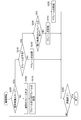
- FIG. 4 is a flowchart showing the processing of the imaging method in the first embodiment.
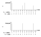
- FIG. 5 is a diagram showing an example of the relationship between the I-frame insertion timing and the frame capacity after compression.
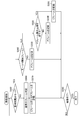
- FIG. 6 is a flowchart showing the processing of the imaging method in the second embodiment.
- FIG. 7 is a diagram showing a state of I-frame insertion in the second embodiment.
- FIG. 8 is a flowchart showing the processing of the imaging method in the third embodiment.
- FIG. 9 is a diagram showing a state of I-frame insertion in the third embodiment.
- FIG. 10 is a diagram for explaining the compression process in the fourth embodiment.
- FIG. 11 is a diagram for explaining the compression process in the fifth embodiment.
- FIG. 12 is a diagram showing a state of display update of the display device in the sixth embodiment.
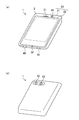
- FIG. 13 is an external view of the smartphone according to the second embodiment.
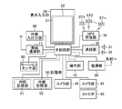
- FIG. 14 is a diagram showing a schematic configuration of a smartphone.
- FIG. 1 is a diagram showing a schematic configuration of a camera 100 (imaging device) according to the first embodiment.
- the camera 100 is composed of an interchangeable lens 200 and an image pickup device main body 300, and a subject image (optical image) is connected to a light receiving unit 312 of the image pickup element 310 (image pickup element) by an image pickup lens including a zoom lens 210 and a focus lens 230 described later. Make an image.
- the interchangeable lens 200 and the image pickup apparatus main body 300 can be attached to and detached from each other via a mount (not shown).
- the lens device optical system
- the lens device optical system
- the interchangeable lens 200 includes a zoom lens 210, a diaphragm 220, a focus lens 230, and a lens driving unit 240.
- the lens drive unit 240 adjusts the zoom (optical zoom) by driving the zoom lens 210 and the focus lens 230 forward and backward in the direction of the optical axis L in response to a command from the CPU 330 (lens drive control unit 340 in FIG. 2; processor). Adjust the focus.
- the zoom adjustment and the focus adjustment may be performed according to a zoom operation or a focus operation (zoom ring (not shown, rotation of the focus ring, etc.)) performed by the user, in addition to being performed in response to a command from the CPU 330.
- the lens driving unit 240 controls the aperture 220 in response to a command from the CPU 330 to adjust the exposure.
- information such as the positions of the zoom lens 210 and the focus lens 230 and the degree of opening of the aperture 220 is input to the CPU 330.
- the image pickup device main body 300 includes an image pickup device 310, a digital signal processing unit 320, a CPU 330, an operation unit 350, a recording device 360 (recording device, memory), a monitor 370 (display device), and a speaker 380.
- the image pickup device main body 300 may have a shutter (not shown) for blocking light transmitted through the image pickup device 310.
- the shutter may be a mechanical shutter or an electronic shutter. In the case of an electronic shutter, the exposure time (shutter speed) can be adjusted by controlling the charge accumulation period of the image sensor 310 by the CPU 330.
- the image sensor 310 includes a light receiving unit 312, an analog amplification unit 314, an A / D converter 316, and an image sensor drive unit 318.
- the light receiving unit 312 includes a light receiving surface in which a large number of light receiving elements are arranged in a matrix. Then, the subject light transmitted through the zoom lens 210, the aperture 220, and the focus lens 230 is imaged on the light receiving surface of the light receiving unit 312, and is converted into an electric signal by each light receiving element.
- An R (red), G (green), or B (blue) color filter is provided on the light receiving surface of the light receiving unit 312, and a color image of the subject can be acquired based on the signals of each color.
- a CMOS (Complementary Metal-Oxide Semiconductor) type color image sensor can be used as the image sensor 310.
- an analog amplification unit 314 is provided for each pixel or a plurality of pixels constituting the light receiving unit 312.
- the pixel signal is amplified by the analog amplification unit 314, read out in units of rows, and supplied to the A / D converter 316 (Analog-to-Digital Converter).
- the A / D converter 316 converts the supplied pixel signal into a digital pixel signal and supplies it to the digital signal processing unit 320.
- the digital signal processing unit 320 converts the digital pixel signal into a digital image signal by performing digital correlation double sampling processing, digital gain processing, correction processing, and the like.
- the image sensor driving unit 318 drives the image sensor 310 in response to a command from the CPU 330 (processor).
- the image sensor drive unit, the analog amplification unit, and the A / D converter are often included in the image sensor package as shown in FIG. 1.
- An image sensor having a configuration different from that of the embodiment may be used.
- a color image sensor such as an XY address type or a CCD (Charge-Coupled Device) type can be used in addition to the CMOS type.
- CCD Charge-Coupled Device
- FIG. 2 is a diagram showing a functional configuration of the CPU 330 (processor).
- the CPU 330 has functions as an image acquisition unit 332, a frame allocation unit 334, a compression recording unit 336, a display control unit 338, and a lens drive control unit 340.
- the CPU 330 performs processing such as imaging, compression, and recording of a moving image based on the digital image signal input from the digital signal processing unit 320. Details of the processing using the CPU 330 will be described later.
- the function of the CPU 330 can be realized by using various processors.
- the various processors include, for example, a CPU (Central Processing Unit), which is a general-purpose processor that executes software (program) to realize various functions.
- the various processors described above include a GPU (Graphics Processing Unit), which is a processor specialized in image processing.
- the various processors described above include PLD (Programmable Logic Device), which is a processor whose circuit configuration can be changed after manufacturing such as FPGA (Field Programmable Gate Array).
- the above-mentioned various processors include a dedicated electric circuit, which is a processor having a circuit configuration specially designed for executing a specific process such as an ASIC (Application Specific Integrated Circuit).
- each function of the CPU 330 may be realized by one processor or may be realized by a plurality of processors. Further, one processor may support a plurality of functions. Further, each function of the CPU 330 may be realized by a circuit, or a part of each function may be realized by a circuit and the rest may be realized by a processor.
- the above-mentioned processor or electric circuit executes software (program)
- the code that can be read by the processor (computer) of the software to be executed and the data necessary for executing the software are stored in non-temporary such as Flash Memory. It is stored in a recording medium, and the processor refers to the software or data.
- the software stored in the non-temporary recording medium includes an image pickup program (a program for operating the image pickup device) for executing the image pickup method according to the present embodiment. Codes and data may be recorded on a non-temporary recording medium using various optical magnetic recording devices, semiconductor memories, or the like instead of the flash memory.
- the "semiconductor memory” includes a ROM (Read Only Memory) and an EEPROM (Electronically Erasable and Programmable ROM) in addition to the flash memory.
- ROM Read Only Memory
- EEPROM Electrically Erasable and Programmable ROM
- RAM RandomAccessMemory
- RAM RandomAccessMemory
- the CPU 330 includes a flash memory 344 (non-temporary recording medium, memory).
- the flash memory 344 is read by a computer (for example, various processors constituting the CPU 330) of a program (including a program for executing the imaging method according to the present embodiment) necessary for image capture, recording, display, and the like. Possible codes and data necessary for executing the program (for example, frame determination conditions such as frame compression and recording patterns, and an upper limit of the number of continuous P-frame recordings) are recorded.
- the CPU 330 includes a temporary storage area and a RAM 348 (memory) as a work area.
- the operation unit 350 has a release button (for example, a cross button, a quick button, an OK button, etc.), a dial, a switch, and the like (for example, a cross button, a quick button, an OK button, etc.), which are not shown, and the user can set an image pickup mode and an image pickup condition (for example, a frame rate of a moving image). And shutter speed, the number of consecutive P-frames and its upper limit, etc.) can be set, moving image imaging instructions, still image imaging instructions, and various other operations can be performed. Further, the CPU 330 can accept the instructions of these users.
- the monitor 370 (display device) may be configured as a touch panel type device so that it can be used as an operation unit.
- the recording device 360 (recording device, memory) is composed of various optical magnetic recording media, a non-temporary recording medium such as a semiconductor memory, and a control circuit thereof, and can store moving images, still images, and the like. As shown in FIG. 3 (a diagram showing information recorded in the recording device 360), for example, the recording device 360 records a moving image 362 or the like recorded by performing the first compression process or the second compression process described later. be able to.
- the recording medium constituting the recording device 360 a type that can be attached to and detached from the image pickup device main body 300 can be used.
- the captured image (moving image, still image) may be configured to be transmittable to an external recording medium or recording device (other than the recording device 360) by, for example, wired and / or wireless communication, and may be recorded on them. ..
- the monitor 370 (display device) is composed of, for example, a touch panel type liquid crystal display panel, and can display set imaging conditions, moving images, still images, warning messages to users, and the like. This message may be output by voice from the speaker 380.
- the monitor 370 can be arranged on the back side, the top surface side, or the like of the image pickup apparatus main body 300.
- the camera 100 may be provided with an optical and / or electronic viewfinder.
- the I-frame insertion pattern (specifically, “how many frames the I-frame is inserted once") is fixed, for example, during long-time exposure (multiple identical frames continue), or When there is little change in the image indicated by each frame (hereinafter, may be referred to as "frame image” or "frame”), such as before changing the exposure control, it may be compressed as an I frame, or at the moment when the image changes. It can happen that it is compressed as a P frame. If many such frames appear, the efficiency of compression will decrease.
- the conventional techniques such as Patent Document 1 described above do not take such circumstances into consideration.
- the inventors of the present application adjust the insertion interval of the I frame according to the exposure control, and use the P frame (and / or the B frame) when it can be predicted that the change in the image is small.
- this method for example, at the time of long exposure, it is recognized how many frames the same frame continues based on the frame rate and the shutter speed, and it is controlled so that the I frame is not recorded at such a place.
- this method for example, at the time of long exposure, it is recognized how many frames the same frame continues based on the frame rate and the shutter speed, and it is controlled so that the I frame is not recorded at such a place.
- FIG. 4 is a flowchart showing the processing of the imaging method in the first embodiment.
- the frame allocation unit 334 sets the camera 100 to the long exposure mode based on the set frame rate (frame recording interval) and shutter speed (exposure time). It is determined whether or not it is present (step S100: exposure mode determination step).
- the "long exposure mode” is an exposure mode in which the exposure time for generating an I frame is longer than the frame recording interval (the exposure time set at the time of imaging is a frame constituting the recorded moving image data). Is longer than the recording interval of).
- step S100 When the exposure time is equal to or less than the recording interval (that is, in the short exposure mode), the determination in step S100 is denied, the frame allocation unit 334 performs a normal frame determination (step S180), and the compression recording unit 336. Records an I-frame or a P-frame (step S190). For example, the frame allocation unit 334 determines "whether or not the P frames are continuous for a fixed number of times", and the compression recording unit 336 can insert one I frame if this determination is affirmed.
- the frame allocation unit 334 When the camera 100 is set to the long exposure mode, and when the imaging mode is switched from the short exposure mode to the long exposure mode (YES in step S100), the frame allocation unit 334 "has already acquired the frame to be recorded. The determination of "whether or not the frame is the same as the frame made" is started (step S110: identity determination step).
- step S110 identity determination step.
- the long exposure mode when a frame based on the image data acquired by the completion of exposure is newly recorded, the frame to be recorded is not the same as the already acquired frame.
- the image data of that frame has not been acquired yet, and the frame based on the image data acquired by the completion of the exposure is repeatedly recorded at a predetermined frame rate (recording interval).
- the frame to be recorded is the same as the frame already acquired.
- the compressed recording unit 336 sets the image data of the frame to be recorded and the image of the frame time before the frame to be recorded.
- a compression process (second compression process) is performed based on the difference information from the data to generate a P frame, and the generated P frame is recorded in the recording device 360 (step S130: PB frame recording step).
- the recorded frame (the image indicated by the frame) is the same as the already acquired frame.
- the frame allocation unit 334 is permitted to allocate an I frame to the frame to be recorded (step S120: frame allocation step). However, in this case, it does not mean that "the frame allocation unit 334 always allocates an I frame". This is for example, when the frame rate is 60 fps (fps: frame per second) and the exposure time is 1/30 sec (the exposure time is not so long with respect to the frame rate), 2 frames (2 frames). ), The image is renewed once, but if I frames are assigned each time the image is renewed, the frame sequence becomes "IPIPIP ", which is rather wasteful in terms of compression efficiency.
- the condition for the long exposure mode is "Y ⁇ X", and the number of times the same frame is generated by the long exposure. Is "roundup (X / Y, 0)" (X is divided by Y and rounded up to the nearest whole number).
- the frame allocation unit 334 discriminates the scene and / or detects the subject in the acquired frame (step S140: frame allocation step), and determines. It is determined whether or not to allocate an I frame according to the result and / or the result of detection (step S150: frame allocation step). For scene discrimination, the frame allocation unit 334 can calculate, for example, the light source type and the color temperature based on the color signals of each color (red, blue, green) output from the image pickup element 310 and their ratios.
- the frame allocation unit 334 detects a new subject, detects a movement of the subject, or detects a person by, for example, calculating the difference between the newly captured frame and the already captured frame. It is possible to detect changes in facial expressions of animals and animals.
- the frame allocation unit 334 allocates an I frame when the scene and / or the subject changes significantly (YES in step S150), performs the first compression process to generate an I frame, and transfers the generated I frame to the recording device 360.
- the first compression process is a compression process based on image data for one frame acquired by the completion of one exposure (a frame whose exposure is completed at a timing before and after the timing of the completion of exposure of the one frame). Compression processing that does not use image data). For example, when the scene is different (the light source type or color temperature has changed), a new subject is detected, or the movement of the subject is equal to or greater than a predetermined amount (greater than or equal to the threshold value).
- the frame allocation unit 334 can determine that "the scene and / or the subject has changed significantly". When the scene and / or the subject changes significantly in this way, it is preferable to allocate an I frame in consideration of image quality.
- the frame allocation unit 334 allocates a P frame (NO in step S150), performs a second compression process, and records at a recording interval corresponding to the frame rate.
- Step S160 PB frame recording step.
- the second compression process is a compression process based on the difference information between the same images, and the data capacity after compression is almost zero (only a value indicating that the data in the frame is zero). This is because, in the long exposure mode, there is no image obtained by capturing the frame recorded at the timing during the exposure period, so the captured image at the timing most recent than that timing is taken as the frame. This is because it is treated as an image (frame recorded at the timing during the exposure period).
- the P frame is recorded as a frame other than the frame in which the I frame is recorded. In this way, when the scene and / or the subject has not changed significantly, it can be efficiently compressed by allocating a P frame.
- steps S100 to S195 are repeated until the imaging of the moving image is completed (until YES is obtained in step S195).
- FIG. 5 is a diagram showing an example of the relationship between the I-frame insertion timing and the frame capacity after compression.
- the frame rate is set to 60 fps and the exposure time is set to 1/12 sec. In this case, the exposure time is 5 times the frame rate.
- five P frames time t2 to t6, time t8 to t12 are continuously recorded for one I frame (time t1, t7).
- Part (a) in FIG. 5 shows a frame pattern when the number of continuous recordings (initial setting) of P frames is maintained.
- an I frame is assigned at a timing (time t7; the same frame as time t6) that can be significantly compressed by using a P frame, and the capacity at this timing is large.
- the part (b) in FIG. 5 shows the pattern of the frame when the frame is assigned in the embodiment of the first embodiment.
- the time t6 is a P frame and the time t7 is an I frame
- the time t6 is an I frame and the time t7 is a P frame.
- This is the frame image No. Is due to the allocation of the I-frame at the timing (time t6) when switching from "1" to "2", and in the flowchart of FIG. 4, it corresponds to the case where NO is determined in step S110 and the I-frame is recorded in step S170. .. It is assumed that there is a large change in the scene and / subject (YES in step S150).
- the moving image can be efficiently compressed while maintaining the image quality.
- the B frame may be recorded in place of the P frame or in addition to the P frame (another embodiment described below, And the same applies to the second embodiment).
- the B frame can be compressed as much as the P frame.
- FIG. 6 is a flowchart showing the processing of the imaging method in the second embodiment. Since the processing in the short exposure mode (steps S260 and S270) is the same as the processing in steps S180 and S190 (see FIG. 4), detailed description thereof will be omitted.
- the frame allocation unit 334 sets the I frame as the frame to be recorded. Is scheduled (step S210: identity determination step). The frame allocation unit 334 sets "whether or not an I frame is scheduled" to the initial setting of "how many frames an I frame is inserted once (the number of consecutive recordings of a P frame for one I frame)". It can be judged based on.
- the compression recording unit 336 When the I-frame is not scheduled, the compression recording unit 336 generates a P-frame in the same manner as in step S130 described above, and records the generated P-frame in the recording device 360 (step S220: PB frame recording step).
- step S210 When an I frame is scheduled as a frame to be recorded (YES in step S210), the frame allocation unit 334 determines "whether or not the frame to be recorded is the same as the already acquired frame" (YES). Step S230: Identity determination step). This determination is the same as in step S110.
- the compression recording unit 336 generates and records a P frame if the judgment is affirmed (step S250: PB frame recording step), and generates and records an I frame if the judgment is negative (step S240: I frame recording step).
- FIG. 7 is a diagram showing a state of I-frame insertion in the second embodiment.
- Part (a) in the figure shows an example of I-frame and P-frame allocation (initial setting).
- the I frame is inserted once every 7 frames. That is, the number of continuous recordings of P frames is 6.
- the frame rate is 60 fps
- the exposure time is 1/60 sec or less (short exposure mode) in the period ⁇ T1
- the exposure time is 1/30 sec (long exposure mode) in the period ⁇ T2. That is, as shown in the part (b) of the figure, the recording frame No. It is assumed that the mode is changed to the long exposure mode at the timing when becomes 3 to 4.
- frame 6B as shown in the "before change" line in part (b) of FIG. Is an I frame
- frame 7A is a P frame. That is, in step S230 of FIG. 6, "the image data of the frame (frame 6B) to be recorded at the timing when the I frame is recorded when the initial setting is followed is the image data of the already acquired frame (frame 6A). Is the same as ".” However, since the frame 6B is the same frame (same as an image) as the previous frame (frame 6A), it is preferable to use a P frame from the viewpoint of efficient compression.
- the compression recording unit 336 records the frame 6B as a P frame as shown in the “changed” line of the portion (b) of FIG. 7 (step S250 of FIG. 6), and newly Frame 7A, which is a new frame (not the same as the already acquired frame; recording frame No. 7), is recorded as an I frame (step S240). That is, when the frame allocation unit 334 (processor) records the frame 6B as a P frame, the initial setting number of continuous recordings of the P frame (6 times in the example of FIG. 7) is changed to 7 times.
- the same processing is performed according to the changed number of times. Specifically, the frame 11A, which is a new frame, is recorded as the next I frame. The above-mentioned processing is performed until the imaging of the moving image is completed (until YES is obtained in step S280).
- the moving image can be efficiently compressed.
- FIG. 8 is a flowchart showing the processing of the imaging method in the third embodiment. Since the processing in the short exposure mode (steps S360, S370) and the determination of whether or not the imaging is completed (step S380) are the same as the processing in steps S180, S190, S195 (see FIG. 4), detailed description is omitted. do. Further, FIG. 9 is a diagram showing a state of insertion of the I frame in the third embodiment. As shown in the part (a) of FIG. 9, it is assumed that the I frame is inserted once every 14 times in the initial setting of the frame allocation (the number of continuous recordings of the P frame is 13 times). In the initial setting, the upper limit of the number of repetitions of the P frame is 18 times. It is assumed that the frame rate is 60 fps and the exposure time is 1/12 sec, that is, the same frame is recorded five times in succession.
- the frame allocation unit 334 determines "whether or not the frame to be recorded is a frame at which continuous recording of the same frame starts". (Step S310: Frame allocation step). If this determination is denied, the compression recording unit 336 performs a second compression process and records a P frame (step S320: PB frame recording step).
- the frame 2A is "a frame at which continuous recording of the same frame (recording frame No. 2) starts", and in the case of such a frame, the judgment of step S310 is affirmative. Will be done. Then, the frame allocation unit 334 determines "whether or not the upper limit of the number of repetitions of the P frame is exceeded by continuous recording" (step S330: frame allocation step). Even if the P frames are recorded five times in succession from the frames 2A described above, the recording frame No.
- step S330 Since the number of repetitions of the P frame totaled from 1 is 9 times, which is within the range of the initial setting, the judgment of step S330 is denied, and the P frame is recorded 5 times in succession as scheduled (the part (b) in FIG. 9). From the "before change” line to the "change 1" line; the result is the same).
- step S330 "If the P frame is continuously recorded 5 times, the total number of continuous recordings from the recording frame No. 1 is 19 times, which is the upper limit of the number of repetitions of the P frame. Since it is determined that "exceeds (18 times)", the compression recording unit 336 (processor) performs the first compression process in step S350 and records an I frame (in the portion (b) of FIG. 9, "change 2". From the line "Change 3").
- the moving image can be efficiently compressed in this way, and the upper limit of the number of repetitions of the P frame is not exceeded.
- FIG. 10 is a diagram for explaining the compression process in the fourth embodiment.
- the frame allocation in the short exposure mode is the pattern shown in the portion (a) of FIG. 10 (I frame is inserted once in 7 frames, and the number of continuous recordings of P frame is 6 times).
- the frame allocation in the long exposure mode has the pattern shown in the part (b) of the figure.
- the compression rate of the image is corrected with reference to the compression rate of the past frames, the compression rate decreases during the period in which the P frames are continuous (time t1 and t2 in the example of FIG. 10), and as a result, the compression rate decreases.
- the capacity (file size) after compression will increase. In this situation, when the I-frame insertion timing comes (time t3), the low compression rate setting of the past frame is inherited, and the I-frame size becomes larger than usual.
- the compression recording unit 336 turns off the setting for referring to the past compression rate (compression rate of the frame time before the frame to be recorded) in the long exposure mode.
- the compression recording unit 336 can use, for example, a predetermined fixed value as the compression rate.
- the compression recording unit 336 may set different compression rates for the I frame and the P frame.
- the compression rate does not change during the continuous period of P frames (including time t1 and t2) as shown in the part (d) of FIG. Therefore, the capacity (file size) remains small, and the capacity of the I frame does not become too large.
- the moving image can be efficiently compressed.
- FIG. 11 is a diagram for explaining the compression process in the fifth embodiment.
- the compression ratio is high during the period (time t1, t2) in which P frames are continuous.
- the capacity (file size) after compression increases.
- time t3 when the I-frame insertion timing comes (time t3), the low compression rate setting of the past frame is inherited, and the I-frame size becomes larger than usual. This can increase the load on the processing power of the allocated processor.
- the compression recording unit 336 uses the CPU 330 at the timing of the I frame (timing at which the first compression process is performed; time t3 and the like in the example of FIG. 11).
- the processing capacity of the (processor) is increased more than the processing capacity at the timing of the P frame (timing at which the second compression process is performed).
- Example 5 when setting the compression rate, the compression rate of the past frame may or may not be referred to.
- Some image pickup devices capable of recording a moving image include a display device for displaying the captured moving image.
- the camera 100 (imaging device) according to the present invention can also display a moving image on the monitor 370. The update of the display in the display of such a moving image will be described below.
- FIG. 12 is a diagram showing a state of display update of the display device in the sixth embodiment.
- the frame rate is 60 fps (recording interval: about 16.6 msec) and the exposure time is 1/12 sec (long exposure) as shown in the part (a) of FIG.
- the part (b) of the figure five identical frames are continuously recorded at a recording interval of about 16.6 msec.
- the display is updated at intervals of about 16.6 msec as shown in the part (c) of the figure, but the display is updated every time the same frame is displayed as shown in the part (c). This may increase the load on the processing power and power consumption of the processor.
- the update of the display is stopped during the period of recording the same frame as the already recorded frame, and the display is updated when the recording of the frame different from the already recorded frame is started.
- the display control unit 338 changes the recorded frame to a new frame (for example, frame No. 1 becomes frame No. 2).
- the display of the monitor 370 is updated.
- Such display update can be performed, for example, by the display control unit 338 not transmitting a display update command to the monitor 370 (decimating the command) during the update stop period.
- Example 6 According to such display control, the period in which the frame is displayed does not change, so that the "appearance" of the moving image can be maintained, and the load on the processing power and power consumption of the processor can be reduced.
- the display control of Example 6 can be applied to the above-mentioned Examples 1 to 5.
- the moving image can be efficiently compressed.
- the camera 100 which is a digital camera, has been described, but the configuration of the image pickup apparatus is not limited to this.
- the other imaging device may be, for example, a built-in or external PC camera (PC: Personal Computer), or a portable terminal device having an imaging function as described below.
- Examples of the mobile terminal device according to the embodiment of the image pickup device of the present invention include mobile phones, smartphones, PDAs (Personal Digital Assistants), portable game machines, and smart watches.
- a smartphone will be taken as an example and will be described in detail with reference to the drawings.
- FIG. 13 is an external view of the smartphone 1 (imaging device) according to the second embodiment.
- the part (a) is a front view and the part (b) is a rear view.
- the smartphone 1 shown in FIG. 13 has a flat plate-shaped housing 2, and has a display panel 21 (display device) as a display unit and an operation panel 22 (operation unit) as an input unit on one surface of the housing 2. Is provided with a display input unit 20 integrated with the above.
- the housing 2 includes a speaker 31 (speaker), a microphone 32, an operation unit 40 (operation unit), camera units 41 and 42 (imaging device), and a strobe 43.
- the configuration of the housing 2 is not limited to this, and for example, a configuration in which the display unit and the input unit are independent may be adopted, or a configuration having a folding structure or a slide mechanism may be adopted.
- FIG. 14 is a diagram showing a schematic configuration of the smartphone 1.
- the smartphone 1 includes a wireless communication unit 11, a display input unit 20, a call unit 30, an operation unit 40, camera units 41 and 42, a strobe 43, a storage unit 50, and an external device. It includes an input / output unit 60, a GPS receiving unit 70 (GPS: Global Positioning System), a motion sensor unit 80, and a power supply unit 90.
- the smartphone 1 includes a main control unit 101 (processor). Further, as a main function of the smartphone 1, it is provided with a wireless communication function for performing mobile wireless communication via a base station device and a mobile communication network.
- the wireless communication unit 11 performs wireless communication with the base station device housed in the mobile communication network according to the instruction of the main control unit 101.
- various file data such as voice data and image data, e-mail data and the like are transmitted and received, and Web data and streaming data and the like are received.
- the display input unit 20 displays images (still images and / or moving images), character information, and the like to visually convey information to the user, and also performs user operations on the displayed information. It is a so-called touch panel for detection, and includes a display panel 21 and an operation panel 22.
- an LCD Liquid Crystal Display
- OLED Organic Light-Emitting Diode
- the operation panel 22 is a device that visually mounts an image displayed on the display surface of the display panel 21 and detects one or a plurality of coordinates operated by a conductor such as a user's finger or a pen.
- a conductor such as a user's finger or a pen
- the operation panel 22 outputs a detection signal generated due to the operation to the main control unit 101.
- the main control unit 101 detects the operation position (coordinates) on the display panel 21 based on the received detection signal.
- the display panel 21 and the operation panel 22 of the smartphone 1 exemplified as an embodiment of the image pickup apparatus of the present invention integrally form a display input unit 20, but the operation panel is formed. 22 is arranged to completely cover the display panel 21.
- the operation panel 22 may have a function of detecting a user operation even in an area outside the display panel 21.
- the operation panel 22 has a detection area (hereinafter referred to as a display area) for the overlapping portion overlapping the display panel 21 and a detection area (hereinafter, non-display area) for the outer edge portion not overlapping the other display panel 21. ) And may be provided.
- the call unit 30 includes a speaker 31 and a microphone 32, converts the user's voice input through the microphone 32 into voice data that can be processed by the main control unit 101, and outputs the data to the main control unit 101.
- the audio data received by the 11 or the external input / output unit 60 can be decoded and output from the speaker 31.
- the speaker 31 can be mounted on the same surface as the surface provided with the display input unit 20, and the microphone 32 can be mounted on the side surface of the housing 2.
- the operation unit 40 is a hardware key using a key switch or the like, and is a device that receives instructions from the user.
- the operation unit 40 is mounted on the side surface of the housing 2 of the smartphone 1, and is turned on when pressed with a finger or the like, and turned off by a restoring force such as a spring when the finger is released. It is a button type switch.
- the storage unit 50 (recording device, memory) includes a control program of the main control unit 101 (for example, a program for causing the main control unit 101 to execute the imaging method of the present embodiment) and control data (as in the frame determination condition 364 of FIG. 3). It may include the frame allocation pattern, the upper limit of the number of continuous recordings of P frames, etc.), application software, address data associated with the name and phone number of the communication partner, data of sent / received e-mail, Web. Web data downloaded by browsing, downloaded content data are stored, and streaming data and the like are temporarily stored. Further, the storage unit 50 stores a moving image captured by the imaging method of the present embodiment.
- the storage unit 50 is composed of an internal storage unit 51 built in the smartphone and an external storage unit 52 having a detachable external memory slot.
- Each of the internal storage unit 51 and the external storage unit 52 constituting the storage unit 50 is realized by using a known storage medium.
- the external input / output unit 60 serves as an interface with all external devices connected to the smartphone 1.
- the smartphone 1 is directly or indirectly connected to another external device via an external input / output unit 60 by communication or the like.
- Examples of means for communication and the like include Universal Serial Bus, IEEE1394, and networks (for example, wired LAN and wireless LAN).
- Bluetooth Bluetooth
- RFID Radio Frequency Identification
- infrared communication Infrared Data Association
- UWB Ultra Wide Band
- ZigBee registered trademark
- the like can also be mentioned as means for communication and the like.
- Examples of the external device connected to the smartphone 1 include a wired / wireless headset, a wired / wireless external charger, and a wired / wireless data port. Further, a memory card (Memory card) and a SIM (Subscriber Identity Module Card) / UIM (User Identity Module Card) card connected via a card socket can also be mentioned as external devices. Also, external audio and video equipment connected via audio and video I / O (Input / Output) terminals, external audio and video equipment wirelessly connected, smartphones wired / wirelessly connected, and wired / wireless connection. External devices such as PDAs, wired / wirelessly connected personal computers, and earphones can also be connected. The external input / output unit 60 can transmit the data transmitted from such an external device to each component inside the smartphone 1 and can transmit the data inside the smartphone 1 to the external device.
- a memory card Memory card
- SIM Subscriber Identity Module Card
- UIM User Identity Module Card
- the motion sensor unit 80 includes, for example, a 3-axis acceleration sensor, an inclination sensor, or the like, and detects the physical movement of the smartphone 1 according to the instruction of the main control unit 101. By detecting the physical movement of the smartphone 1, the moving direction, acceleration, and posture of the smartphone 1 are detected. Such a detection result is output to the main control unit 101.
- the power supply unit 90 supplies electric power stored in a battery (not shown) to each unit of the smartphone 1 according to the instruction of the main control unit 101.
- the main control unit 101 includes a microprocessor and a memory (memory) such as RAM and flash memory, operates according to the control program and control data stored in the storage unit 50, and controls each unit of the smartphone 1 including the camera unit 41. To control.
- the frame allocation pattern, the upper limit of the number of repetitions of the P frame, and the like may be stored in the memory of the main control unit 101.
- the main control unit 101 includes a mobile communication control function for controlling each unit of the communication system and an application processing function for performing voice communication and data communication through the wireless communication unit 11.
- the main control unit 101 is provided with an image processing function such as displaying an image on the display input unit 20 based on image data (still image or moving image data) such as received data or downloaded streaming data.
- the image processing function refers to a function in which the main control unit 101 decodes image data, performs image processing on the decoding result, and displays the image on the display input unit 20.
- the camera units 41 and 42 are digital cameras (imaging devices) that perform electronic imaging using an image pickup element such as CMOS or CCD. Further, the camera units 41 and 42 convert the image data (moving image, still image) obtained by imaging into compressed image data such as MPEG or JPEG under the control of the main control unit 101, and record the image data in the storage unit 50. In addition, it can be output through the external input / output unit 60 and the wireless communication unit 11 (during such compression and recording, the first compression process is performed by the image pickup method of the present embodiment in the same manner as in the first embodiment. And the second compression process can be performed).
- the smartphone 1 shown in FIGS. 13 and 14 one of the camera units 41 and 42 can be used for image capture, or the camera units 41 and 42 can be used at the same time for image capture. When the camera unit 42 is used, the strobe 43 can be used.
- the camera units 41 and 42 can be used for various functions of the smartphone 1.
- the smartphone 1 can display the images acquired by the camera units 41 and 42 on the display panel 21. Further, the smartphone 1 can use the images of the camera units 41 and 42 as one of the operation inputs of the operation panel 22.
- the GPS receiving unit 70 detects the position based on the positioning information from the GPS satellites ST1, ST2, ..., STn
- the smartphone 1 detects the position by referring to the images from the camera units 41 and 42. You can also do it.
- the smartphone 1 refers to the images from the camera units 41 and 42, and the light of the camera unit 41 of the smartphone 1 is used without using the 3-axis accelerometer or in combination with the 3-axis accelerometer.
- the smartphone 1 can also use the images from the camera units 41 and 42 in the application software.
- the smartphone 1 has image data of a still image or a moving image, position information acquired by the GPS receiving unit 70, and voice information acquired by the microphone 32 (voice text conversion is performed by the main control unit or the like to obtain text information. It is also possible to add posture information or the like acquired by the motion sensor unit 80 and record it in the storage unit 50. Further, the smartphone 1 can also output the image data of these still images or moving images through the external input / output unit 60 and the wireless communication unit 11.
- the smartphone 1 having the above-described configuration also has the processing of the imaging method according to the present embodiment (imaging of a moving image, determination of a scene, detection of a subject and its movement, detection of a frame). Allocation, first compression processing, second compression processing, etc .; including an I-frame recording step and a PB frame recording step) can be executed.
- the processing (including the processing of the flowcharts of FIGS. 4, 6 and 8) executed by the CPU 330 (each part shown in FIG. 2) in the first embodiment is mainly performed by the camera units 41 and 42 and the main in the smartphone 1.
- the control unit 101 can be executed.
- the functions of the operation unit 350, the recording device 360, the monitor 370, and the speaker 380 in the first embodiment are the operation unit 40, the storage unit 50 and the operation panel 22, the display panel 21, the operation panel 22, and the speaker 31 in the smartphone 1. Each can be realized by.
- the smartphone 1 according to the second embodiment can also obtain the same effect as the camera 100 according to the first embodiment (the moving image can be efficiently compressed).
Landscapes
- Engineering & Computer Science (AREA)
- Multimedia (AREA)
- Signal Processing (AREA)
- Physics & Mathematics (AREA)
- General Physics & Mathematics (AREA)
- Studio Devices (AREA)
- Compression Or Coding Systems Of Tv Signals (AREA)
- Television Signal Processing For Recording (AREA)
Abstract
動画像を効率的に圧縮できる撮像装置、撮像方法、及び撮像プログラムを提供する。本発明の一態様では、撮像装置は、プロセッサを備え、動画像を撮像する撮像装置であって、プロセッサは、撮像する際に設定される露光時間が、記録される動画像データを構成するフレームの記録間隔より長い長時間露光モードにおいて、露光完了のタイミングに基づいて、露光の完了により取得された画像データに基づいて第1圧縮処理を行ってIフレームを生成し、フレームとしてIフレームを記録し、画像データに基づいて第2圧縮処理を行ってPフレームまたはBフレームを生成し、Iフレームが記録されるフレーム以外のフレームとしてPフレームまたはBフレームを記録する。
Description
本発明は、動画像を撮像する撮像装置、撮像方法、及び撮像プログラムに関する。
動画を撮像するための技術に関し、例えば特許文献1には、動画像の圧縮符号化を行う撮像装置が記載されている。
本開示の技術に係る一つの実施形態は、動画像を効率的に圧縮できる撮像装置、撮像方法、及び撮像プログラムを提供する。
本発明の第1の態様に係る撮像装置は、プロセッサを備え、動画像を撮像する撮像装置であって、プロセッサは、撮像する際に設定される露光時間が、記録される動画像データを構成するフレームの記録間隔より長い長時間露光モードにおいて、露光完了のタイミングに基づいて、露光の完了により取得された画像データに基づいて第1圧縮処理を行ってIフレームを生成し、フレームとしてIフレームを記録し、画像データに基づいて第2圧縮処理を行ってPフレームまたはBフレームを生成し、Iフレームが記録されるフレーム以外のフレームとしてPフレームまたはBフレームを記録する。
第2の態様に係る撮像装置は第1の態様において、プロセッサは、画像データにおいてシーンの判別及び/または被写体の検出を行い、判別の結果及び/または検出の結果に応じて画像データに第1圧縮処理を行ってIフレームを生成し、生成したIフレームを記録する。
第3の態様に係る撮像装置は第2の態様において、プロセッサは、画像データは既に記録された画像データとシーンが異なると判断された場合、被写体が新たに検出された場合、及び被写体の動きが決められた量以上であることが検出された場合は、画像データに第1圧縮処理を行ってIフレームを生成し、生成したIフレームを記録する。
第4の態様に係る撮像装置は第1の態様において、1つのIフレームに対するPフレームまたはBフレームの連続記録回数が初期設定されており、プロセッサは、長時間露光モードにおいて、初期設定に従った場合にIフレームが記録されるタイミングで記録すべきフレームの画像データが、既に取得されたフレームの画像データと同一であるか否かを判定し、判定の結果に応じて画像データに基づいて第1圧縮処理または第2圧縮処理を行ってIフレーム、Pフレーム、またはBフレームを生成し、生成したIフレーム、Pフレーム、またはBフレームを記録する。
第5の態様に係る撮像装置は第4の態様において、プロセッサは、初期設定に従った場合にIフレームが記録されるタイミングで記録すべきフレームの画像データが既に取得されたフレームの画像データと同一であると判定された場合、初期設定された連続記録回数を変更して、画像データに基づいて第2圧縮処理を行ってPフレームまたはBフレームを生成して記録し、初期設定に従った場合にIフレームが記録されるタイミングで記録すべきフレームが既に取得されたフレームと異なると判定された場合、画像データに第1圧縮処理を行ってIフレームを生成して記録する。
第6の態様に係る撮像装置は第4または第5の態様において、露光時間が記録間隔以下である短時間露光モードを有し、プロセッサは、動画像の撮像モードが短時間露光モードから長時間露光モードに切り替わったら判定を開始する。
第7の態様に係る撮像装置は第1の態様において、プロセッサは、長時間露光モードにおいて、記録対象のフレームが同一フレームの連続記録が開始するフレームであるか否か、及び連続記録によりPフレームまたはBフレームの繰り返し回数の上限を超えるか否か、に基づいてIフレームの生成及び記録、もしくはPフレームまたはBフレームの生成及び記録を行う。
第8の態様に係る撮像装置は第7の態様において、繰り返し回数の上限を示す情報が記憶されたメモリをさらに備え、プロセッサは、長時間露光モードにおいて、フレームの記録間隔と露光時間とに基づいて、同一のフレームが連続記録される回数を算出し、記録対象のフレームが既に記録されたフレームと同一であるか否かを判定し、記録対象のフレームが既に記録されたフレームと同一でないと判定された場合に、連続記録される回数が繰り返し回数の上限を超える場合は第1圧縮処理を行い、連続記録される回数が繰り返し回数の上限を超えない場合は第2圧縮処理を行う。
第9の態様に係る撮像装置は第1から第8の態様のいずれか1つにおいて、プロセッサは、長時間露光モードにおいて、記録対象のフレームの圧縮率を、記録対象のフレームよりも時間的に前のフレームの圧縮率を参照せずに設定し、記録対象のフレームを、設定した圧縮率で圧縮して記録する。
第10の態様に係る撮像装置は第1から第9の態様のいずれか1つにおいて、プロセッサは、長時間露光モードにおいて、第1圧縮処理を行う際のプロセッサの処理能力を、第2圧縮処理を行う際のプロセッサの処理能力よりも上げる。
第11の態様に係る撮像装置は第1から第10の態様のいずれか1つにおいて、プロセッサは、長時間露光モードにおいて、動画像を表示装置に表示させ、表示を行う際に、既に記録されたフレームと同一のフレームを記録する期間は表示の更新を停止し、既に記録されたフレームと異なるフレームの記録を開始したら表示の更新を行う。
本発明の第12の態様に係る撮像方法は、動画像を撮像する撮像装置の撮像方法であって、撮像する際に設定される露光時間が、記録される動画像データを構成するフレームの記録間隔より長い長時間露光モードにおいて、露光完了のタイミングに基づいて、露光の完了により取得された画像データに基づいて第1圧縮処理を行ってIフレームを生成し、フレームとしてIフレームを記録するIフレーム記録ステップと、画像データに基づいて第2圧縮処理を行ってPフレームまたはBフレームを生成し、Iフレームが記録されるフレーム以外のフレームとしてPフレームまたはBフレームを記録するPBフレーム記録ステップと、を有する。第12の態様に係る撮像方法は、第2から第11の態様と同様の構成を備えていてもよい。
本発明の第13の態様に係る撮像プログラムは、プロセッサを備え、動画像を撮像する撮像装置に撮像方法を実行させる撮像プログラムであって、プロセッサにより、撮像する際に設定される露光時間が、記録される動画像データを構成するフレームの記録間隔より長い長時間露光モードにおいて、露光完了のタイミングに基づいて、露光の完了により取得された画像データに基づいて第1圧縮処理を行ってIフレームを生成し、フレームとしてIフレームを記録するIフレーム記録ステップと、画像データに基づいて第2圧縮処理を行ってPフレームまたはBフレームを生成し、Iフレームが記録されるフレーム以外のフレームとしてPフレームまたはBフレームを記録するPBフレーム記録ステップと、を行わせる。第13の態様に係る撮像プログラムは、第2から第11の態様と同様の構成をコンピュータに実行させてもよい。なお、これら態様の撮像プログラムのコンピュータ読み取り可能なコードを記録した非一時的記録媒体も、本発明の態様として挙げることができる。
本発明に係る撮像装置、撮像方法、及び撮像プログラムの一つの実施形態は以下の通りである。説明においては、必要に応じて添付図面が参照される。
<第1の実施形態>
<撮像装置の全体構成>
図1は第1の実施形態に係るカメラ100(撮像装置)の概略構成を示す図である。カメラ100は交換レンズ200及び撮像装置本体300により構成され、後述するズームレンズ210,フォーカスレンズ230を含む撮像レンズにより、被写体像(光学像)を撮像素子310(撮像素子)の受光部312に結像させる。交換レンズ200と撮像装置本体300とは、図示せぬマウントを介して装着及び取り外しをすることができる。なお、第1の実施形態ではカメラ100が交換レンズ200を備える場合について説明しているが、レンズ装置(光学系)がカメラ本体に固定されていてもよい。
<撮像装置の全体構成>
図1は第1の実施形態に係るカメラ100(撮像装置)の概略構成を示す図である。カメラ100は交換レンズ200及び撮像装置本体300により構成され、後述するズームレンズ210,フォーカスレンズ230を含む撮像レンズにより、被写体像(光学像)を撮像素子310(撮像素子)の受光部312に結像させる。交換レンズ200と撮像装置本体300とは、図示せぬマウントを介して装着及び取り外しをすることができる。なお、第1の実施形態ではカメラ100が交換レンズ200を備える場合について説明しているが、レンズ装置(光学系)がカメラ本体に固定されていてもよい。
<交換レンズの構成>
交換レンズ200は、ズームレンズ210と、絞り220と、フォーカスレンズ230と、レンズ駆動部240と、を備える。レンズ駆動部240は、CPU330(図2のレンズ駆動制御部340;プロセッサ)からの指令に応じてズームレンズ210、フォーカスレンズ230を光軸Lの方向に進退駆動してズーム(光学ズーム)調整、フォーカス調整を行う。ズーム調整及びフォーカス調整は、CPU330からの指令に応じて行う他に、ユーザが行ったズーム操作、フォーカス操作(図示せぬズームリング、フォーカスリングの回動等)に応じて行ってもよい。また、レンズ駆動部240は、CPU330からの指令に応じて絞り220を制御し、露出を調整する。一方、ズームレンズ210及びフォーカスレンズ230の位置、絞り220の開放度等の情報がCPU330に入力される。
交換レンズ200は、ズームレンズ210と、絞り220と、フォーカスレンズ230と、レンズ駆動部240と、を備える。レンズ駆動部240は、CPU330(図2のレンズ駆動制御部340;プロセッサ)からの指令に応じてズームレンズ210、フォーカスレンズ230を光軸Lの方向に進退駆動してズーム(光学ズーム)調整、フォーカス調整を行う。ズーム調整及びフォーカス調整は、CPU330からの指令に応じて行う他に、ユーザが行ったズーム操作、フォーカス操作(図示せぬズームリング、フォーカスリングの回動等)に応じて行ってもよい。また、レンズ駆動部240は、CPU330からの指令に応じて絞り220を制御し、露出を調整する。一方、ズームレンズ210及びフォーカスレンズ230の位置、絞り220の開放度等の情報がCPU330に入力される。
<撮像装置本体の構成>
撮像装置本体300は、撮像素子310、デジタル信号処理部320、CPU330、操作部350、記録装置360(記録装置、メモリ)、モニタ370(表示装置)、及びスピーカ380を備える。撮像装置本体300は、撮像素子310に透過させる光を遮光するためのシャッター(不図示)を有していてもよい。なお、シャッターは、メカニカルシャッターでも電子シャッターでもよい。電子シャッターの場合、CPU330が撮像素子310の電荷蓄積期間を制御することで、露光時間(シャッタースピード)を調節することができる。
撮像装置本体300は、撮像素子310、デジタル信号処理部320、CPU330、操作部350、記録装置360(記録装置、メモリ)、モニタ370(表示装置)、及びスピーカ380を備える。撮像装置本体300は、撮像素子310に透過させる光を遮光するためのシャッター(不図示)を有していてもよい。なお、シャッターは、メカニカルシャッターでも電子シャッターでもよい。電子シャッターの場合、CPU330が撮像素子310の電荷蓄積期間を制御することで、露光時間(シャッタースピード)を調節することができる。
<撮像素子の構成>
撮像素子310は、受光部312、アナログ増幅部314、A/D変換器316、及び撮像素子駆動部318を備える。
撮像素子310は、受光部312、アナログ増幅部314、A/D変換器316、及び撮像素子駆動部318を備える。
受光部312は、多数の受光素子がマトリクス状に配列された受光面を備える。そして、ズームレンズ210、絞り220、及びフォーカスレンズ230を透過した被写体光が受光部312の受光面上に結像され、各受光素子によって電気信号に変換される。受光部312の受光面上にはR(赤),G(緑),またはB(青)のカラーフィルタが設けられており、各色の信号に基づいて被写体のカラー画像を取得することができる。なお、本実施形態では、撮像素子310としてCMOS(Complementary Metal-Oxide Semiconductor)型のカラーイメージセンサを用いることができる。
CMOS型のイメージセンサの構成の一例においては、受光部312を構成する画素ごとまたは複数の画素ごとに、アナログ増幅部314が設けられる。画素信号は、アナログ増幅部314において増幅された後、行単位で読み出され、A/D変換器316(Analog-to-Digital Converter)に供給される。A/D変換器316は、供給された画素信号をデジタル画素信号に変換し、デジタル信号処理部320に供給する。デジタル信号処理部320は、デジタル画素信号をデジタル相関二重サンプリング処理、デジタルゲイン処理、補正処理等を行って、デジタル画像信号に変換する。撮像素子駆動部318は、CPU330(プロセッサ)からの指令に応じて撮像素子310を駆動する。
撮像素子310がCMOS型のイメージセンサである場合、図1に示す態様のように撮像素子駆動部、アナログ増幅部、及びA/D変換器が撮像素子のパッケージに含まれることが多いが、この態様と異なる構成のイメージセンサを用いてもよい。
なお、撮像素子310として、CMOS型の他に、XYアドレス型、CCD(Charge-Coupled Device)型等のカラーイメージセンサを用いることができる。
<CPUの構成>
図2は、CPU330(プロセッサ)の機能構成を示す図である。CPU330は、画像取得部332、フレーム割当部334、圧縮記録部336、表示制御部338、及びレンズ駆動制御部340としての機能を有する。CPU330は、デジタル信号処理部320から入力されたデジタル画像信号に基づいて、動画像の撮像及び圧縮、記録等の処理を行う。CPU330を用いた処理の詳細は後述する。
図2は、CPU330(プロセッサ)の機能構成を示す図である。CPU330は、画像取得部332、フレーム割当部334、圧縮記録部336、表示制御部338、及びレンズ駆動制御部340としての機能を有する。CPU330は、デジタル信号処理部320から入力されたデジタル画像信号に基づいて、動画像の撮像及び圧縮、記録等の処理を行う。CPU330を用いた処理の詳細は後述する。
CPU330の機能は、各種のプロセッサ(processor)を用いて実現できる。各種のプロセッサには、例えばソフトウェア(プログラム)を実行して各種の機能を実現する汎用的なプロセッサであるCPU(Central Processing Unit)が含まれる。また、上述した各種のプロセッサには、画像処理に特化したプロセッサであるGPU(Graphics Processing Unit)が含まれる。また、上述した各種のプロセッサには、FPGA(Field Programmable Gate Array)などの製造後に回路構成を変更可能なプロセッサであるPLD(Programmable Logic Device)も含まれる。さらに、ASIC(Application Specific Integrated Circuit)などの特定の処理を実行させるために専用に設計された回路構成を有するプロセッサである専用電気回路なども上述した各種のプロセッサに含まれる。
なお、CPU330の各機能は1つのプロセッサで実現されていてもよいし、複数のプロセッサで実現されていてもよい。また、1つのプロセッサが複数の機能に対応していてもよい。さらに、CPU330の各機能は回路によって実現されていてもよく、また各機能の一部が回路で実現され、残りがプロセッサによって実現されていてもよい。
上述したプロセッサあるいは電気回路がソフトウェア(プログラム)を実行する際は、実行するソフトウェアのプロセッサ(コンピュータ)読み取り可能なコードや、ソフトウェアの実行に必要なデータをフラッシュメモリ(Flash Memory)等の非一時的記録媒体に記憶しておき、プロセッサがそのソフトウェアやデータを参照する。非一時的記録媒体に記憶しておくソフトウェアは、本実施形態に係る撮像方法を実行するための撮像プログラム(撮像装置を動作させるプログラム)を含む。フラッシュメモリではなく各種光磁気記録装置、半導体メモリ等を用いた非一時的記録媒体にコードやデータを記録してもよい。ここで、「半導体メモリ」にはフラッシュメモリの他にROM(Read Only Memory)やEEPROM(Electronically Erasable and Programmable ROM)が含まれる。ソフトウェアを用いた処理の際には例えばRAM(Random Access Memory)が一時的記憶領域として用いられる。
図2に示すように、CPU330はフラッシュメモリ344(非一時的記録媒体、メモリ)を備える。フラッシュメモリ344には、画像の撮像、記録、表示等に必要なプログラム(本実施形態に係る撮像方法を実行するためのプログラムを含む)のコンピュータ(例えば、CPU330を構成する各種のプロセッサ)で読み取り可能なコードや、プログラムの実行に際し必要なデータ(例えば、フレームの圧縮や記録のパターン、Pフレーム連続記録回数の上限値等のフレーム判定条件)が記録される。また、CPU330は、一時的な記憶領域及び作業領域としてのRAM348(メモリ)を備える。
<操作部>
操作部350は図示せぬレリーズボタン、操作用ボタン(例えば十字ボタン、Quickボタン、OKボタン等)、ダイヤル、スイッチ等を有し、ユーザは撮像モード設定、撮像条件(例えば、動画像のフレームレート及びシャッタースピード、Pフレームの連続回数及びその上限等)の設定、動画撮像指示、静止画撮像指示等、各種の操作を行うことができる。また、CPU330は、これらユーザの指示を受け付けることができる。なお、モニタ370(表示装置)をタッチパネル型のデバイスで構成し、操作部として使用可能としてもよい。
操作部350は図示せぬレリーズボタン、操作用ボタン(例えば十字ボタン、Quickボタン、OKボタン等)、ダイヤル、スイッチ等を有し、ユーザは撮像モード設定、撮像条件(例えば、動画像のフレームレート及びシャッタースピード、Pフレームの連続回数及びその上限等)の設定、動画撮像指示、静止画撮像指示等、各種の操作を行うことができる。また、CPU330は、これらユーザの指示を受け付けることができる。なお、モニタ370(表示装置)をタッチパネル型のデバイスで構成し、操作部として使用可能としてもよい。
<記録装置>
記録装置360(記録装置、メモリ)は各種の光磁気記録媒体、半導体メモリ等の非一時的記録媒体及びその制御回路により構成され、動画、静止画等を保存することができる。記録装置360には、例えば図3(記録装置360に記録される情報を示す図)に示すように、後述する第1圧縮処理または第2圧縮処理を行って記録した動画像362等を記録することができる。記録装置360を構成する記録媒体としては、撮像装置本体300に対し着脱できるタイプを用いることができる。撮像した画像(動画像、静止画像)を、例えば有線及び/または無線通信により外部の(記録装置360以外の)記録媒体や記録装置に送信可能な構成とし、それらに記録できるようにしてもよい。
記録装置360(記録装置、メモリ)は各種の光磁気記録媒体、半導体メモリ等の非一時的記録媒体及びその制御回路により構成され、動画、静止画等を保存することができる。記録装置360には、例えば図3(記録装置360に記録される情報を示す図)に示すように、後述する第1圧縮処理または第2圧縮処理を行って記録した動画像362等を記録することができる。記録装置360を構成する記録媒体としては、撮像装置本体300に対し着脱できるタイプを用いることができる。撮像した画像(動画像、静止画像)を、例えば有線及び/または無線通信により外部の(記録装置360以外の)記録媒体や記録装置に送信可能な構成とし、それらに記録できるようにしてもよい。
<モニタ及びスピーカ>
モニタ370(表示装置)は例えばタッチパネル型の液晶表示パネルにより構成され、設定された撮像条件、動画像、静止画像、ユーザへの警告メッセージ等を表示することができる。このメッセージはスピーカ380から音声出力してもよい。モニタ370は撮像装置本体300の背面側、天面側等に配置することができる。なお、カメラ100は光学式及び/または電子式のビューファインダを備えていてもよい。
モニタ370(表示装置)は例えばタッチパネル型の液晶表示パネルにより構成され、設定された撮像条件、動画像、静止画像、ユーザへの警告メッセージ等を表示することができる。このメッセージはスピーカ380から音声出力してもよい。モニタ370は撮像装置本体300の背面側、天面側等に配置することができる。なお、カメラ100は光学式及び/または電子式のビューファインダを備えていてもよい。
<長時間露光での動画撮像における課題及び本願発明の手法>
デジタルカメラにて動画撮像を行う際、記録容量の増大を防ぐため、圧縮した画像を記録することが一般的である。圧縮はフレームごとに独立して行う(Iフレーム)だけでなく、前フレームとの差分情報のみ圧縮する(Pフレーム)ことや、時間的に前のフレームのみでなく後のフレームとの差分情報から圧縮する(Bフレーム)ことが可能である。そして、決められたパターンに従ってこれらのフレームのいずれかを用いることで圧縮効率を上げることが一般的である。しかしながら、Iフレーム挿入のパターン(具体的には、「何フレームに1回Iフレームが挿入されるか」)が固定されている場合、例えば長時間露光(全く同じフレームが複数続く)時や、露出制御の変更前など、各フレームが示す画像(以下、「フレーム画像」あるいは「コマ」という場合がある)の変化が少ないときにIフレームとして圧縮してしまうことや、画像が変化する瞬間にPフレームとして圧縮してしまうことが起こり得る。そのようなフレームが多く出現すると、圧縮の効率が下がってしまう。しかしながら、上述した特許文献1等の従来の技術は、このような事情を考慮したものではなかった。
デジタルカメラにて動画撮像を行う際、記録容量の増大を防ぐため、圧縮した画像を記録することが一般的である。圧縮はフレームごとに独立して行う(Iフレーム)だけでなく、前フレームとの差分情報のみ圧縮する(Pフレーム)ことや、時間的に前のフレームのみでなく後のフレームとの差分情報から圧縮する(Bフレーム)ことが可能である。そして、決められたパターンに従ってこれらのフレームのいずれかを用いることで圧縮効率を上げることが一般的である。しかしながら、Iフレーム挿入のパターン(具体的には、「何フレームに1回Iフレームが挿入されるか」)が固定されている場合、例えば長時間露光(全く同じフレームが複数続く)時や、露出制御の変更前など、各フレームが示す画像(以下、「フレーム画像」あるいは「コマ」という場合がある)の変化が少ないときにIフレームとして圧縮してしまうことや、画像が変化する瞬間にPフレームとして圧縮してしまうことが起こり得る。そのようなフレームが多く出現すると、圧縮の効率が下がってしまう。しかしながら、上述した特許文献1等の従来の技術は、このような事情を考慮したものではなかった。
このような事情に鑑みて、本願発明者らは、露出制御に合わせてIフレームの挿入間隔を調整し、画像の変化が少ないと予測できる場合はPフレーム(及び/またはBフレーム)を使用することで、効率よい圧縮を可能とする手法を開発した。この手法では、例えば長時間露光時、フレームレートとシャッタースピードに基づいて全く同じフレームが何フレーム続くか認識し、そのような箇所でIフレームが記録されないように制御する。以下、この手法の具体的態様を説明する。
<撮像方法の処理(実施例1)>
図4は、実施例1での撮像方法の処理を示すフローチャートである。動画像の撮像が始まると、フレーム割当部334(プロセッサ)は、設定されたフレームレート(フレームの記録間隔)及びシャッタースピード(露光時間)に基づいて、カメラ100が長時間露光モードに設定されているか否かを判定する(ステップS100:露光モード判定ステップ)。「長時間露光モード」とは、Iフレームを生成するための露光時間が、フレームの記録間隔より長い露光モード(撮像する際に設定される露光時間が、記録される動画像データを構成するフレームの記録間隔より長い)である。露光時間が記録間隔以下である場合(すなわち、短時間露光モードである場合)はステップS100の判断が否定され、フレーム割当部334は通常のフレーム判定を行って(ステップS180)、圧縮記録部336はIフレームまたはPフレームを記録する(ステップS190)。例えば、フレーム割当部334は「Pフレームが決められた数連続しているか否か」を判断し、圧縮記録部336はこの判断が肯定されたらIフレームを1つ挿入することができる。
図4は、実施例1での撮像方法の処理を示すフローチャートである。動画像の撮像が始まると、フレーム割当部334(プロセッサ)は、設定されたフレームレート(フレームの記録間隔)及びシャッタースピード(露光時間)に基づいて、カメラ100が長時間露光モードに設定されているか否かを判定する(ステップS100:露光モード判定ステップ)。「長時間露光モード」とは、Iフレームを生成するための露光時間が、フレームの記録間隔より長い露光モード(撮像する際に設定される露光時間が、記録される動画像データを構成するフレームの記録間隔より長い)である。露光時間が記録間隔以下である場合(すなわち、短時間露光モードである場合)はステップS100の判断が否定され、フレーム割当部334は通常のフレーム判定を行って(ステップS180)、圧縮記録部336はIフレームまたはPフレームを記録する(ステップS190)。例えば、フレーム割当部334は「Pフレームが決められた数連続しているか否か」を判断し、圧縮記録部336はこの判断が肯定されたらIフレームを1つ挿入することができる。
カメラ100が長時間露光モードに設定されている場合、及び撮像モードが短時間露光モードから長時間露光モードに切り替わったら(ステップS100でYES)、フレーム割当部334は「記録対象のフレームが既に取得されたフレームと同一であるか否か」の判定を開始する(ステップS110:同一性判断ステップ)。なお、長時間露光モードにおいて、露光の完了により取得された画像データに基づくフレームを新たに記録する場合は、記録対象のフレームは既に取得されたフレームと同一ではない。一方、あるフレームの露光期間中は、そのフレームの画像データがまだ取得されておらず露光の完了により取得された画像データに基づくフレームを決められたフレームレート(記録間隔)で繰り返し記録するので、記録対象のフレームは既に取得されたフレームと同一となる。
記録対象のフレームが既に取得されたフレームと同一である場合(ステップS110でYES)、圧縮記録部336は、記録対象のフレームの画像データと、記録対象のフレームより時間的に前のフレームの画像データとの差分情報に基づく圧縮処理(第2圧縮処理)を行ってPフレームを生成し、生成したPフレームを記録装置360に記録する(ステップS130:PBフレーム記録ステップ)。記録されるフレーム(フレームが示す画像)は、既に取得されたフレームと同一である。
記録対象のフレームが既に取得されたフレームと同一ではない場合(ステップS110でNO)、フレーム割当部334が記録対象のフレームにIフレームを割り当てることが許可される(ステップS120:フレーム割当ステップ)。ただし、この場合「フレーム割当部334が必ずIフレームを割り当てる」というわけではない。これは、例えばフレームレートが60fps(fps:frame per second、1秒あたりのフレーム数)で露光時間が1/30sec(露光時間がフレームレートに対してあまり長くない)の場合、2コマ(2フレーム)に1回画像が新しくなるが、画像が新しくなる度にIフレームを割り当ててしまうとフレームのシーケンスが「IPIPIP...」となり、圧縮効率という意味ではむしろ無駄が多くなるためである。なお、動画像のフレームレートをX(fps)、露光時間を1/Y(sec)とすると、長時間露光モードとなる条件は“Y<X”であり、長時間露光による同一コマの発生回数は“roundup(X/Y,0)”である(XをYで割って小数点以下を切り上げる)。
このような観点から、実施例1では、Iフレームの割り当てが許可される場合でも以下の処理を行った上でIフレームまたはPフレームを記録する。具体的には、ステップS120でIフレームの割当が許可された場合、フレーム割当部334は、取得したフレームにおいてシーンの判別及び/または被写体の検出を行い(ステップS140:フレーム割当ステップ)、判別の結果及び/または検出の結果に応じて、Iフレームを割り当てるか否かを判断する(ステップS150:フレーム割当ステップ)。シーンの判別については、フレーム割当部334が、例えば撮像素子310から出力される各色(赤色、青色、緑色)の色信号及びそれらの比に基づいて光源種や色温度を算出することができる。また、被写体の検出については、フレーム割当部334が、例えば新たに取り込んだフレームと既に取り込まれたフレームとの差分を算出すること等により、新たな被写体の検出や被写体の動きの検出、あるいは人や動物の表情の変化の検出等を行うことができる。
フレーム割当部334は、シーン及び/または被写体が大きく変化した場合はIフレームを割り当て(ステップS150でYES)、第1圧縮処理を行ってIフレームを生成し、生成したIフレームを記録装置360に記録する(ステップS170:Iフレーム記録ステップ)。第1圧縮処理は、1回の露光の完了により取得された、1フレーム分の画像データに基づく圧縮処理(当該1フレームの露光完了のタイミングよりも時間的に前後のタイミングで露光完了したフレームの画像データを用いない圧縮処理)である。なお、例えばシーンが異なる(光源種や色温度が変化した)場合、新たな被写体が検出された場合、あるいは被写体の動きが決められた量以上である(しきい値以上である)場合に、フレーム割当部334は「シーン及び/または被写体が大きく変化した」と判断することができる。このようにシーン及び/または被写体が大きく変化した場合、画質を考慮するとIフレームを割り当てることが好ましい。
一方、シーン及び/または被写体が大きく変化していない場合、フレーム割当部334はPフレームを割り当て(ステップS150でNO)、第2の圧縮処理を行って、フレームレートに対応する記録間隔で記録する(ステップS160:PBフレーム記録ステップ)。長時間露光モードにおいて第2の圧縮処理は同一画像同士の差分情報に基づく圧縮処理であり、圧縮後のデータ容量はほぼゼロ(そのフレームのデータがゼロであることを示す値のみ)になる。これは、長時間露光モードの場合、露光期間中のタイミングで記録されるフレームに対しては撮像して得られた画像が存在しないため、そのタイミングより直近過去のタイミングでの撮像画像をそのフレーム(露光期間中のタイミングで記録されるフレーム)の画像として扱うためである。この結果、ステップS130,S160において、Iフレームが記録されるフレーム以外のフレームとしてPフレームが記録される。このように、シーン及び/または被写体が大きく変化していない場合は、Pフレームを割り当てることで効率的に圧縮することができる。
上述したステップS100~S195の処理は、動画像の撮像が終了するまで(ステップS195でYESになるまで)繰り返される。
図5は、Iフレーム挿入タイミングと圧縮後のフレーム容量との関係の例を示す図である。同図では、フレームレートが60fps、露光時間が1/12secに設定されているものとする。この場合、露光時間はフレームレートの5倍である。また、初期設定では1つのIフレーム(時刻t1,t7)に対し5つのPフレーム(時刻t2~t6,時刻t8~t12)が連続して記録されるように設定されているものとする。
図5の(a)部分はPフレームの連続記録回数(初期設定)を維持した場合のフレームのパターンを示している。この例では、Pフレームを用いれば大幅に圧縮できるタイミング(時刻t7;時刻t6と同一のフレーム)においてIフレームを割り当てており、このタイミングでの容量が大きくなっている。
一方、図5の(b)部分は、実施例1の態様でフレームを割り当てた場合のフレームのパターンを示している。上述した図5の(a)部分に示す例では時刻t6がPフレーム、時刻t7がIフレームであるが、同図の(b)部分では時刻t6がIフレーム、時刻t7がPフレームである。これは、フレーム画像No.が「1」から「2」に切り替わるタイミング(時刻t6)でIフレームを割り当てたためであり、図4のフローチャートでは、ステップS110でNOと判断されてステップS170でIフレームを記録した場合に相当する。なお、シーン及び/被写体について大きな変化があった(ステップS150でYES)ものとしている。
このようなフレームの割り当てによれば、時刻t7でPフレームを割り当てることで大幅な圧縮が可能となり、またフレーム画像No.が「1」から「2」に切り替わる時刻t6でIフレームを割り当てることで良好な画質で動画像を記録することができる。
なお、図5の(b)部分に示す例では、実施例1の態様でのフレーム割り当ての結果、1つのIフレーム(時刻t1,t6)に対し4つのPフレーム(時刻t2~t5,時刻t7~t10)が連続して記録されており、初期設定と異なるパターンとなっている。
以上説明したように、実施例1によれば、画質を維持しつつ動画像を効率的に圧縮することができる。
なお、実施例1ではIフレーム及びPフレームを記録する場合について説明したが、Pフレームに代えて、またはPフレームに加えてBフレームを記録してもよい(以下に説明する他の実施例、及び第2の実施形態でも同様である)。Bフレームは、Pフレームと同様に大きく圧縮することができる。
<撮像方法の処理(実施例2)>
図6は、実施例2での撮像方法の処理を示すフローチャートである。短時間露光モードの場合の処理(ステップS260,S270)の処理はステップS180,S190(図4を参照)の処理と同様なので、詳細な説明を省略する。
図6は、実施例2での撮像方法の処理を示すフローチャートである。短時間露光モードの場合の処理(ステップS260,S270)の処理はステップS180,S190(図4を参照)の処理と同様なので、詳細な説明を省略する。
カメラ100が長時間露光モードに設定されている場合、及び撮像モードが短時間露光モードから長時間露光モードに切り替わった場合(ステップS200でYES)、フレーム割当部334は記録対象のフレームとしてIフレームが予定されているかを判断する(ステップS210:同一性判断ステップ)。フレーム割当部334は、「Iフレームが予定されているか否か」を、「何フレームに1回Iフレームが挿入されるか(1つのIフレームに対するPフレームの連続記録回数)」の初期設定に基づいて判断することができる。Iフレームが予定されていない場合、圧縮記録部336は上述したステップS130と同様にしてPフレームを生成し、生成したPフレームを記録装置360に記録する(ステップS220:PBフレーム記録ステップ)。
記録対象のフレームとしてIフレームが予定されている場合(ステップS210でYES)、フレーム割当部334は、「記録対象のフレームが既に取得されたフレームと同一であるか否か」の判定を行う(ステップS230:同一性判断ステップ)。この判断は、ステップS110と同様である。圧縮記録部336は判断が肯定されたらPフレームを生成及び記録し(ステップS250:PBフレーム記録ステップ)、判断が否定されたらIフレームを生成及び記録する(ステップS240:Iフレーム記録ステップ)。
図7は実施例2におけるIフレーム挿入の様子を示す図である。同図の(a)部分はIフレーム及びPフレームの割り当て(初期設定)の例を示す。この例では、7フレームに1回、Iフレームが挿入される。すなわち、Pフレームの連続記録回数は6回である。そして、フレームレートが60fps、期間ΔT1では露光時間が1/60sec以下(短時間露光モード)、期間ΔT2で露光時間が1/30sec(長時間露光モード)になるものとする。すなわち、同図の(b)部分に示すように、記録コマNo.が3から4になるタイミングで長時間露光モードに移行したものとする。
このような状況で、Iフレーム及びPフレームの割り当てが初期状態(図7の(a)部分)にしたがっている場合、図7の(b)部分の「変更前」の行に示すようにフレーム6BがIフレームとなり、フレーム7AがPフレームとなる。すなわち、図6のステップS230において、「初期設定に従った場合にIフレームが記録されるタイミングで記録すべきフレーム(フレーム6B)の画像データが、既に取得されたフレーム(フレーム6A)の画像データと同一である」と判定されることになる。しかしながら、フレーム6Bは前のフレーム(フレーム6A)と同一のコマ(画像として同一)であるから、効率的な圧縮の観点からはPフレームとすることが好ましい。このような場合、実施例2では、圧縮記録部336は図7の(b)部分の「変更後」の行に示すようにフレーム6BをPフレームとして記録し(図6のステップS250)、新たなコマ(既に取得されたフレームと同一でない;記録コマNo.7)となるフレーム7AをIフレームとして記録する(ステップS240)。すなわち、フレーム割当部334(プロセッサ)は、フレーム6BをPフレームとして記録するに際して、初期設定されたPフレームの連続記録回数(図7の例では6回)を変更して7回としている。
連続記録回数の変更後は、変更後の回数により同様の処理が行われる。具体的には、新たなコマとなるフレーム11Aが次のIフレームとして記録される。上述の処理は、動画像の撮像が終了するまで(ステップS280でYESになるまで)行われる。
以上説明したように、実施例2によれば動画像を効率的に圧縮することができる。
<撮像方法の処理(実施例3)>
図8は、実施例3での撮像方法の処理を示すフローチャートである。短時間露光モードの場合の処理(ステップS360,S370)及び撮像終了か否かの判断(ステップS380)はステップS180,S190,S195(図4を参照)の処理と同様なので、詳細な説明を省略する。また、図9は実施例3におけるIフレームの挿入の様子を示す図である。図9の(a)部分に示すように、フレーム割り当ての初期設定ではIフレームが14回に1回挿入される設定(Pフレームの連続記録回数は13回)になっているものとする。また、初期設定ではPフレームの繰り返し回数の上限は18回であるものとする。なお、フレームレートは60fpsで露光時間は1/12sec、すなわち同一のフレームが5回連続して記録されるものとする。
図8は、実施例3での撮像方法の処理を示すフローチャートである。短時間露光モードの場合の処理(ステップS360,S370)及び撮像終了か否かの判断(ステップS380)はステップS180,S190,S195(図4を参照)の処理と同様なので、詳細な説明を省略する。また、図9は実施例3におけるIフレームの挿入の様子を示す図である。図9の(a)部分に示すように、フレーム割り当ての初期設定ではIフレームが14回に1回挿入される設定(Pフレームの連続記録回数は13回)になっているものとする。また、初期設定ではPフレームの繰り返し回数の上限は18回であるものとする。なお、フレームレートは60fpsで露光時間は1/12sec、すなわち同一のフレームが5回連続して記録されるものとする。
このような状況で長時間露光モードの場合(ステップS300でYES)、フレーム割当部334(プロセッサ)は、「記録対象のフレームが同一フレームの連続記録が開始するフレームであるか否か」を判断する(ステップS310:フレーム割当ステップ)。この判断が否定されると、圧縮記録部336は第2圧縮処理を行ってPフレームを記録する(ステップS320:PBフレーム記録ステップ)。
図9の(b)部分に示す例では、例えばフレーム2Aが「同一フレーム(記録コマNo.2)の連続記録が開始するフレーム」であり、このようなフレームの場合にステップS310の判断が肯定される。するとフレーム割当部334は、「連続記録によりPフレームの繰り返し回数の上限を超えるか否か」を判断する(ステップS330:フレーム割当ステップ)。上述したフレーム2AからPフレームが5回連続して記録されても、記録コマNo.1から通算したPフレームの繰り返し回数は9回であり初期設定の範囲内なので、ステップS330の判断が否定され、予定通りPフレームが5回連続して記録される(図9の(b)部分において、「変更前」の行から「変更1」の行へ;結果は同じ)。
Pフレームの連続記録(5回)による記録コマNo.2の記録が終了し、記録コマNo.3の記録が開始されると、フレーム3Aのタイミングで、再度「同一フレーム(記録コマNo.3)の連続記録が開始するフレーム」と判断される(ステップS310でYES)。この場合、Pフレームを連続して5回記録すると記録コマNo.1から通算しての連続記録回数は14回となり、初期設定に従えば記録コマNo.3の途中でIフレームが挿入されることになるが、Pフレームの繰り返し回数の上限(18回)は超えない。したがって、この場合もステップS330の判断が否定され、記録コマNo.3の期間もPフレームが連続して記録される(図9の(b)部分において「変更1」の行から「変更2」の行へ;ステップS340)。
さらに処理が進んで記録コマNo.3の記録が終了し、記録コマNo.4の記録が開始される。このときは、フレーム4Aのタイミングでは、ステップS330において「Pフレームを連続して5回記録すると、記録コマNo.1から通算しての連続記録回数は19回となり、Pフレームの繰り返し回数の上限(18回)を超える」と判断されるので、ステップS350に進んで圧縮記録部336(プロセッサ)が第1圧縮処理を行い、Iフレームを記録する(図9の(b)部分において「変更2」の行から「変更3」の行へ)。なお、このような「Pフレームの繰り返し回数が上限を超えることによるIフレームの挿入」は、画質及び圧縮効率の観点から、同一フレームの繰り返し記録の最初のコマ(図9の例ではフレーム4A)で行うことが好ましい。
実施例3によれば、このようにして動画像を効率的に圧縮することができ、またPフレームの繰り返し回数の上限を超えることもない。
<撮像方法の処理(実施例4)>
目標ファイルサイズ(目標ビットレート)を達成するために画像の圧縮率を適宜修正するシステムが有り、このようなシステムでは、一般的に過去のフレームの圧縮率を参照している。上述した長時間露光によって同一コマあるいはPフレームが続いている際は、圧縮効率が良くデータサイズが小さくなるため、目標ファイルサイズにするために圧縮率を落とし、データサイズを大きくする動作となる。
目標ファイルサイズ(目標ビットレート)を達成するために画像の圧縮率を適宜修正するシステムが有り、このようなシステムでは、一般的に過去のフレームの圧縮率を参照している。上述した長時間露光によって同一コマあるいはPフレームが続いている際は、圧縮効率が良くデータサイズが小さくなるため、目標ファイルサイズにするために圧縮率を落とし、データサイズを大きくする動作となる。
図10は、実施例4における圧縮処理を説明するための図である。例えば、短時間露光モードでのフレーム割り当てが図10の(a)部分に示すパターン(7フレームに1回Iフレームを挿入、Pフレームの連続記録回数は6回)であり、これに対し実施例3のようなPフレームの連続記録回数に基づく制御を行った結果、長時間露光モードでのフレーム割り当てが同図の(b)部分に示すパターンになったものとする。この場合、過去のフレームの圧縮率を参照して画像の圧縮率を修正すると、Pフレームが連続している期間(図10の例では時刻t1,t2)では圧縮率が下がっていき、その結果圧縮後の容量(ファイルサイズ)は増加していく。この状況でIフレーム挿入のタイミングになると(時刻t3)、過去フレームの低圧縮率設定を引き継いでしまい、Iフレームのサイズが通常より大きくなってしまう。
そこで実施例4では、圧縮記録部336は、長時間露光モードにおいて過去の圧縮率(記録対象のフレームよりも時間的に前のフレームの圧縮率)を参照する設定をOFFする。この場合、圧縮記録部336は、例えばあらかじめ決められた固定値を圧縮率として用いることができる。圧縮記録部336は、IフレームとPフレームとで異なる圧縮率を設定してもよい。
このように過去のフレームの圧縮率を参照する設定をOFFすることにより、図10の(d)部分に示すようにPフレームが連続する期間(時刻t1,t2を含む)で圧縮率が変わらないので容量(ファイルサイズ)は小さいままであり、Iフレームの容量も大きくなりすぎることがない。このように、実施例4によれば動画像を効率的に圧縮することができる。
<撮像方法の処理(実施例5)>
図11は、実施例5における圧縮処理を説明するための図である。上述した実施例4と同様に、目標ファイルサイズ(目標ビットレート)を達成するために過去のフレームの圧縮率を参照して記録対象となる画像の圧縮率を適宜修正するシステムを想定すると、図11の(a)部分~(c)部分(図10の(a)部分~(c)部分と同じ)に示すように、Pフレームが連続している期間(時刻t1,t2)では圧縮率が下がっていき、その結果圧縮後の容量(ファイルサイズ)は増加していく。この状況でIフレーム挿入のタイミングになると(時刻t3)、過去フレームの低圧縮率設定を引き継いでしまい、Iフレームのサイズが通常より大きくなってしまう。これにより、割り当てられたプロセッサの処理能力に対する負荷が高くなるおそれがある。
図11は、実施例5における圧縮処理を説明するための図である。上述した実施例4と同様に、目標ファイルサイズ(目標ビットレート)を達成するために過去のフレームの圧縮率を参照して記録対象となる画像の圧縮率を適宜修正するシステムを想定すると、図11の(a)部分~(c)部分(図10の(a)部分~(c)部分と同じ)に示すように、Pフレームが連続している期間(時刻t1,t2)では圧縮率が下がっていき、その結果圧縮後の容量(ファイルサイズ)は増加していく。この状況でIフレーム挿入のタイミングになると(時刻t3)、過去フレームの低圧縮率設定を引き継いでしまい、Iフレームのサイズが通常より大きくなってしまう。これにより、割り当てられたプロセッサの処理能力に対する負荷が高くなるおそれがある。
そこで実施例5では、図11の(d)部分に示すように、圧縮記録部336(プロセッサ)はIフレームのタイミング(第1圧縮処理を行うタイミング;図11の例では時刻t3等)におけるCPU330(プロセッサ)の処理能力をPフレームのタイミング(第2圧縮処理を行うタイミング)での処理能力よりも上げる。これによりファイルサイズが大きくなったIフレームに対応することができ、動画像を効率的に圧縮することができる。
なお、実施例5では、圧縮率の設定に際し過去のフレームの圧縮率を参照してもよいし、参照しなくてもよい。
<撮像方法の処理(実施例6)>
動画像を記録可能な撮像装置においては、撮像した動画像を表示する表示デバイスを備えているものがある。本願発明に係るカメラ100(撮像装置)も、モニタ370に動画像を表示させることができる。このような動画像の表示における表示の更新について、以下説明する。
動画像を記録可能な撮像装置においては、撮像した動画像を表示する表示デバイスを備えているものがある。本願発明に係るカメラ100(撮像装置)も、モニタ370に動画像を表示させることができる。このような動画像の表示における表示の更新について、以下説明する。
図12は実施例6における表示デバイスの表示更新の様子を示す図である。この例では、フレームレートが60fps(記録間隔:約16.6msec)で、図12の(a)部分に示すように、露光時間が1/12sec(長時間露光)であるものとする。この場合、同図の(b)部分に示すように、約16.6msecの記録間隔で同一のフレームが5つ連続記録される。通常の表示デバイスでは、同図の(c)部分に示すように約16.6msecの間隔で表示が更新されるが、(c)部分のように同一のフレームを表示するのに毎回表示を更新することによりプロセッサの処理能力や消費電力に対する負荷が増大するおそれがある。
そこで本願発明に係るカメラ100では、既に記録されたフレームと同一のフレームを記録する期間は表示の更新を停止し、既に記録されたフレームと異なるフレームの記録を開始したら表示の更新を行う。具体的には、図12の(d)部分に示すように、表示制御部338(プロセッサ)は、記録されるフレームが新たなフレームに変わったら(例えば、フレームNo.1がフレームNo.2に切り替わったら)、モニタ370の表示を更新する。このような表示の更新は、例えば、表示制御部338が更新停止期間中はモニタ370に対し表示更新の指令を送信しない(指令を間引く)ことにより行うことができる。
このような表示制御によれば、フレームが表示される期間は変わらないので動画表示の「見た目」を維持することができ、またプロセッサの処理能力や消費電力に対する負荷を低減することができる。なお、実施例6の表示制御は上述した実施例1~5に適用することができる。
以上説明したように、第1の実施形態に係る撮像装置(カメラ100)、撮像方法、及び撮像プログラムによれば、動画像を効率的に圧縮することができる。
<第2の実施形態>
第1の実施形態では、デジタルカメラであるカメラ100について説明したが、撮像装置の構成はこれに限定されない。その他の撮像装置としては、例えば、内蔵型または外付け型のPC用カメラ(PC:Personal Computer)、あるいは、以下に説明するような、撮像機能を有する携帯端末装置とすることができる。
第1の実施形態では、デジタルカメラであるカメラ100について説明したが、撮像装置の構成はこれに限定されない。その他の撮像装置としては、例えば、内蔵型または外付け型のPC用カメラ(PC:Personal Computer)、あるいは、以下に説明するような、撮像機能を有する携帯端末装置とすることができる。
本発明の撮像装置の一実施形態である携帯端末装置としては、例えば、携帯電話機やスマートフォン、PDA(Personal Digital Assistants)、携帯型ゲーム機、スマートウォッチが挙げられる。以下、スマートフォンを例に挙げ、図面を参照しつつ、詳細に説明する。
図13は第2の実施形態に係るスマートフォン1(撮像装置)の外観図である。同図の(a)部分は正面図、(b)部分は背面図である。図13に示すスマートフォン1は平板状の筐体2を有し、筐体2の一方の面に表示部としての表示パネル21(表示装置)と、入力部としての操作パネル22(操作部)とが一体となった表示入力部20を備えている。また、筐体2は、スピーカ31(スピーカ)と、マイクロフォン32、操作部40(操作部)と、カメラ部41,42(撮像装置)、ストロボ43とを備えている。なお、筐体2の構成はこれに限定されず、例えば、表示部と入力部とが独立した構成を採用してもよいし、折り畳み構造やスライド機構を有する構成を採用してもよい。
図14は、スマートフォン1の概略構成を示す図である。図14に示すように、スマートフォン1は、無線通信部11と、表示入力部20と、通話部30と、操作部40と、カメラ部41,42と、ストロボ43と、記憶部50と、外部入出力部60と、GPS受信部70(GPS:Global Positioning System)と、モーションセンサ部80と、電源部90と、を備える。また、スマートフォン1は、主制御部101(プロセッサ)を備える。また、スマートフォン1の主たる機能として、基地局装置と移動通信網とを介した移動無線通信を行う無線通信機能を備える。
無線通信部11は、主制御部101の指示にしたがって、移動通信網に収容された基地局装置に対し無線通信を行う。斯かる無線通信を使用して、音声データ、画像データ等の各種ファイルデータ、電子メールデータなどの送受信や、Webデータやストリーミングデータなどの受信を行う。
表示入力部20は、主制御部101の制御により、画像(静止画像及び/または動画像)や文字情報などを表示して視覚的にユーザに情報を伝達すると共に、表示した情報に対するユーザ操作を検出する、いわゆるタッチパネルであって、表示パネル21と、操作パネル22とを備える。
表示パネル21においては、LCD(Liquid Crystal Display)、OLED(Organic Light-Emitting Diode)などが表示デバイスとして用いられる。操作パネル22は、表示パネル21の表示面上に表示される画像を視認可能に載置され、ユーザの指やペン等の導体によって操作される1または複数の座標を検出するデバイスである。斯かるデバイスをユーザの指やペン等の導体によって操作すると、操作パネル22は、操作に起因して発生する検出信号を主制御部101に出力する。次いで、主制御部101は、受信した検出信号に基づいて、表示パネル21上の操作位置(座標)を検出する。
図13に示すように、本発明の撮像装置の一実施形態として例示しているスマートフォン1の表示パネル21と操作パネル22とは一体となって表示入力部20を構成しているが、操作パネル22が表示パネル21を完全に覆う配置となっている。斯かる配置を採用した場合、操作パネル22は、表示パネル21外の領域についても、ユーザ操作を検出する機能を備えてもよい。換言すると、操作パネル22は、表示パネル21に重なる重畳部分についての検出領域(以下、表示領域と称する)と、それ以外の表示パネル21に重ならない外縁部分についての検出領域(以下、非表示領域と称する)とを備えていてもよい。
通話部30は、スピーカ31やマイクロフォン32を備え、マイクロフォン32を通じて入力されたユーザの音声を主制御部101にて処理可能な音声データに変換して主制御部101に出力すること、無線通信部11あるいは外部入出力部60により受信された音声データを復号してスピーカ31から出力することができる。また、図13に示すように、例えばスピーカ31を表示入力部20が設けられた面と同じ面に搭載し、マイクロフォン32を筐体2の側面に搭載することができる。
操作部40は、キースイッチなどを用いたハードウェアキーであって、ユーザからの指示を受け付けるデバイスである。例えば図13に示すように、操作部40は、スマートフォン1の筐体2の側面に搭載され、指などで押下されるとオンとなり、指を離すとバネなどの復元力によってオフ状態となる押しボタン式のスイッチである。
記憶部50(記録装置、メモリ)は、主制御部101の制御プログラム(例えば、本実施形態の撮像方法を主制御部101に実行させるプログラム)や制御データ(図3のフレーム判定条件364のような、フレームの割り当てパターンやPフレームの連続記録数の上限等を含んでいてもよい)、アプリケーションソフトウェア、通信相手の名称や電話番号などを対応づけたアドレスデータ、送受信した電子メールのデータ、WebブラウジングによりダウンロードしたWebデータや、ダウンロードしたコンテンツデータを記憶し、またストリーミングデータなどを一時的に記憶する。また、記憶部50は、本実施形態の撮像方法により撮像した動画像を記憶する。また、記憶部50は、スマートフォン内蔵の内部記憶部51と着脱自在な外部メモリスロットを有する外部記憶部52により構成される。なお、記憶部50を構成するそれぞれの内部記憶部51と外部記憶部52は、公知の格納媒体を用いて実現される。
外部入出力部60は、スマートフォン1に連結される全ての外部機器とのインターフェースの役割を果たす。スマートフォン1は、外部入出力部60を介して他の外部機器に通信等により直接的または間接的に接続される。通信等の手段としては、例えば、ユニバーサルシリアルバス(Universal Serial Bus)、IEEE1394、ネットワーク(例えば、有線LAN、無線LAN)を挙げることができる。この他、ブルートゥース(Bluetooth)(登録商標)、RFID(Radio Frequency Identification)、赤外線通信(Infrared Data Association)(登録商標)などを通信等の手段として挙げることができる。さらに、UWB(Ultra Wide Band)(登録商標)、ジグビー(ZigBee)(登録商標)なども通信等の手段として挙げることができる。
スマートフォン1に連結される外部機器としては、例えば、有線/無線ヘッドセット、有線/無線外部充電器、有線/無線データポートを挙げることができる。また、カードソケットを介して接続されるメモリカード(Memory card)やSIM(Subscriber Identity Module Card)/UIM(User Identity Module Card)カードも外部機器として挙げることができる。また、オーディオ及びビデオI/O(Input/Output)端子を介して接続される外部オーディオ及びビデオ機器、無線接続される外部オーディオ及びビデオ機器、有線/無線接続されるスマートフォン、有線/無線接続されるPDA、有線/無線接続されるパーソナルコンピュータ、イヤホンなどの外部機器も連結することができる。外部入出力部60は、このような外部機器から伝送を受けたデータをスマートフォン1の内部の各構成要素に伝達することや、スマートフォン1の内部のデータを外部機器に伝送することができる。
モーションセンサ部80は、例えば、3軸の加速度センサや傾斜センサなどを備え、主制御部101の指示にしたがって、スマートフォン1の物理的な動きを検出する。スマートフォン1の物理的な動きを検出することにより、スマートフォン1の動く方向や加速度、姿勢が検出される。斯かる検出結果は、主制御部101に出力されるものである。電源部90は、主制御部101の指示にしたがって、スマートフォン1の各部に、バッテリ(不図示)に蓄えられる電力を供給する。
主制御部101は、マイクロプロセッサ及びRAMやフラッシュメモリ等のメモリ(メモリ)を備え、記憶部50が記憶する制御プログラムや制御データにしたがって動作し、カメラ部41を含むスマートフォン1の各部を統括して制御する。フレームの割り当てパターンやPフレームの繰り返し回数の上限等を主制御部101のメモリに記憶してもよい。また、主制御部101は、無線通信部11を通じて、音声通信やデータ通信を行うために、通信系の各部を制御する移動通信制御機能と、アプリケーション処理機能を備える。
また、主制御部101は、受信データやダウンロードしたストリーミングデータなどの画像データ(静止画像や動画像のデータ)に基づいて映像を表示入力部20に表示する等の画像処理機能を備える。画像処理機能とは、主制御部101が画像データを復号し、斯かる復号結果に画像処理を施して画像を表示入力部20に表示する機能のことをいう。
カメラ部41,42は、CMOSやCCDなどの撮像素子を用いて電子撮像するデジタルカメラ(撮像装置)である。また、カメラ部41,42は、主制御部101の制御により、撮像によって得た画像データ(動画、静止画)を例えばMPEGやJPEGなどの圧縮した画像データに変換し、記憶部50に記録することや、外部入出力部60や無線通信部11を通じて出力することができる(このような圧縮や記録の際に、本実施形態の撮像方法により、第1の実施形態と同様に第1圧縮処理及び第2圧縮処理を行うことができる)。図13,14に示すスマートフォン1において、カメラ部41,42の一方を用いて撮像することもできるし、カメラ部41,42を同時に使用して撮像することもできる。カメラ部42を用いる場合は、ストロボ43を使用することができる。
また、カメラ部41,42はスマートフォン1の各種機能に利用することができる。例えば、スマートフォン1は、表示パネル21にカメラ部41,42で取得した画像を表示できる。また、スマートフォン1は、操作パネル22の操作入力のひとつとして、カメラ部41,42の画像を利用することができる。また、スマートフォン1は、GPS受信部70がGPS衛星ST1,ST2,…,STnからの測位情報に基づいて位置を検出する際に、カメラ部41,42からの画像を参照して位置を検出することもできる。さらには、スマートフォン1は、カメラ部41,42からの画像を参照して、3軸の加速度センサを用いずに、あるいは、3軸の加速度センサと併用して、スマートフォン1のカメラ部41の光軸方向を判断することや、現在の使用環境を判断することもできる。勿論、スマートフォン1は、カメラ部41,42からの画像をアプリケーションソフトウェア内で利用することもできる。その他、スマートフォン1は、静止画または動画の画像データにGPS受信部70により取得した位置情報、マイクロフォン32により取得した音声情報(主制御部等により、音声テキスト変換を行ってテキスト情報となっていてもよい)、モーションセンサ部80により取得した姿勢情報等を付加して記憶部50に記録することもできる。また、スマートフォン1は、これらの静止画または動画の画像データを外部入出力部60や無線通信部11を通じて出力することもできる。
上述した構成のスマートフォン1においても、第1の実施形態に係るカメラ100と同様に、本実施形態に係る撮像方法の処理(動画像の撮像、シーンの判定、被写体及びその動きの検出、フレームの割り当て、第1圧縮処理及び第2圧縮処理等;Iフレーム記録ステップ及びPBフレーム記録ステップを含む)を実行することができる。具体的には、第1の実施形態においてCPU330(図2に示す各部)が実行する処理(図4,6,8のフローチャートの処理を含む)を、スマートフォン1では主としてカメラ部41,42及び主制御部101が実行できる。その他、第1の実施形態における操作部350、記録装置360、モニタ370、スピーカ380の機能は、スマートフォン1において操作部40、記憶部50及び操作パネル22、表示パネル21及び操作パネル22、スピーカ31によりそれぞれ実現することができる。
これにより、第2の実施形態に係るスマートフォン1においても、第1の実施形態に係るカメラ100と同様の効果(動画像を効率的に圧縮することができる)を得ることができる。
以上で本発明の実施形態について説明してきたが、本発明は上述した態様に限定されず、本発明の精神を逸脱しない範囲で種々の変形が可能である。
1A フレーム
1B フレーム
1C フレーム
1D フレーム
1E フレーム
2A フレーム
3A フレーム
4A フレーム
6A フレーム
6B フレーム
7A フレーム
1 スマートフォン
2 筐体
11 無線通信部
11A フレーム
20 表示入力部
21 表示パネル
22 操作パネル
30 通話部
31 スピーカ
32 マイクロフォン
40 操作部
41 カメラ部
42 カメラ部
43 ストロボ
50 記憶部
51 内部記憶部
52 外部記憶部
60 外部入出力部
70 GPS受信部
80 モーションセンサ部
90 電源部
100 カメラ
101 主制御部
200 交換レンズ
210 ズームレンズ
220 絞り
230 フォーカスレンズ
240 レンズ駆動部
300 撮像装置本体
310 撮像素子
312 受光部
314 アナログ増幅部
316 A/D変換器
318 撮像素子駆動部
320 デジタル信号処理部
330 CPU
332 画像取得部
334 フレーム割当部
336 圧縮記録部
338 表示制御部
340 レンズ駆動制御部
344 フラッシュメモリ
348 RAM
350 操作部
360 記録装置
362 動画像
364 フレーム判定条件
370 モニタ
380 スピーカ
L 光軸
ST1 GPS衛星
ST2 GPS衛星
ΔT1 期間
ΔT2 期間
S100~S380 撮像方法の各ステップ
1B フレーム
1C フレーム
1D フレーム
1E フレーム
2A フレーム
3A フレーム
4A フレーム
6A フレーム
6B フレーム
7A フレーム
1 スマートフォン
2 筐体
11 無線通信部
11A フレーム
20 表示入力部
21 表示パネル
22 操作パネル
30 通話部
31 スピーカ
32 マイクロフォン
40 操作部
41 カメラ部
42 カメラ部
43 ストロボ
50 記憶部
51 内部記憶部
52 外部記憶部
60 外部入出力部
70 GPS受信部
80 モーションセンサ部
90 電源部
100 カメラ
101 主制御部
200 交換レンズ
210 ズームレンズ
220 絞り
230 フォーカスレンズ
240 レンズ駆動部
300 撮像装置本体
310 撮像素子
312 受光部
314 アナログ増幅部
316 A/D変換器
318 撮像素子駆動部
320 デジタル信号処理部
330 CPU
332 画像取得部
334 フレーム割当部
336 圧縮記録部
338 表示制御部
340 レンズ駆動制御部
344 フラッシュメモリ
348 RAM
350 操作部
360 記録装置
362 動画像
364 フレーム判定条件
370 モニタ
380 スピーカ
L 光軸
ST1 GPS衛星
ST2 GPS衛星
ΔT1 期間
ΔT2 期間
S100~S380 撮像方法の各ステップ
Claims (14)
- プロセッサを備え、動画像を撮像する撮像装置であって、
前記プロセッサは、
撮像する際に設定される露光時間が、記録される動画像データを構成するフレームの記録間隔より長い長時間露光モードにおいて、
露光完了のタイミングに基づいて、露光の完了により取得された画像データに基づいて第1圧縮処理を行ってIフレームを生成し、前記フレームとしてIフレームを記録し、
前記画像データに基づいて第2圧縮処理を行ってPフレームまたはBフレームを生成し、前記Iフレームが記録されるフレーム以外の前記フレームとしてPフレームまたはBフレームを記録する撮像装置。 - 前記プロセッサは、
前記画像データにおいてシーンの判別及び/または被写体の検出を行い、
前記判別の結果及び/または前記検出の結果に応じて前記画像データに前記第1圧縮処理を行って前記Iフレームを生成し、
前記生成した前記Iフレームを記録する請求項1に記載の撮像装置。 - 前記プロセッサは、
前記画像データは既に記録された画像データとシーンが異なると判断された場合、
前記被写体が新たに検出された場合、及び
前記被写体の動きが決められた量以上であることが検出された場合は、
前記画像データに前記第1圧縮処理を行って前記Iフレームを生成し、
前記生成したIフレームを記録する請求項2に記載の撮像装置。 - 1つのIフレームに対するPフレームまたはBフレームの連続記録回数が初期設定されており、
前記プロセッサは、前記長時間露光モードにおいて、
前記初期設定に従った場合に前記Iフレームが記録されるタイミングで記録すべきフレームの画像データが、既に取得されたフレームの画像データと同一であるか否かを判定し、
前記判定の結果に応じて前記画像データに基づいて前記第1圧縮処理または前記第2圧縮処理を行ってIフレーム、Pフレーム、またはBフレームを生成し、
前記生成したIフレーム、Pフレーム、またはBフレームを記録する請求項1に記載の撮像装置。 - 前記プロセッサは、
前記初期設定に従った場合に前記Iフレームが記録されるタイミングで記録すべきフレームの画像データが既に取得されたフレームの画像データと同一であると判定された場合、前記初期設定された前記連続記録回数を変更して、前記画像データに基づいて前記第2圧縮処理を行って前記Pフレームまたは前記Bフレームを生成して記録し、
前記初期設定に従った場合に前記Iフレームが記録されるタイミングで記録すべきフレームが既に取得されたフレームと異なると判定された場合、前記画像データに前記第1圧縮処理を行って前記Iフレームを生成して記録する請求項4に記載の撮像装置。 - 前記露光時間が前記記録間隔以下である短時間露光モードを有し、
前記プロセッサは、
前記動画像の撮像モードが前記短時間露光モードから前記長時間露光モードに切り替わったら前記判定を開始する請求項4または5に記載の撮像装置。 - 前記プロセッサは、前記長時間露光モードにおいて、
記録対象のフレームが同一フレームの連続記録が開始するフレームであるか否か、及び
前記連続記録により前記PフレームまたはBフレームの繰り返し回数の上限を超えるか否か、
に基づいて前記Iフレームの生成及び記録、もしくは前記PフレームまたはBフレームの生成及び記録を行う請求項1に記載の撮像装置。 - 前記繰り返し回数の上限を示す情報が記憶されたメモリをさらに備え、
前記プロセッサは、前記長時間露光モードにおいて、
前記フレームの前記記録間隔と前記露光時間とに基づいて、同一のフレームが連続記録される回数を算出し、
記録対象のフレームが既に記録されたフレームと同一であるか否かを判定し、
記録対象のフレームが既に記録されたフレームと同一でないと判定された場合に、
前記連続記録される回数が前記繰り返し回数の上限を超える場合は前記第1圧縮処理を行い、
前記連続記録される回数が前記繰り返し回数の上限を超えない場合は前記第2圧縮処理を行う請求項7に記載の撮像装置。 - 前記プロセッサは、前記長時間露光モードにおいて、
記録対象のフレームの圧縮率を、前記記録対象のフレームよりも時間的に前のフレームの圧縮率を参照せずに設定し、
前記記録対象のフレームを、前記設定した圧縮率で圧縮して記録する請求項1から8のいずれか1項に記載の撮像装置。 - 前記プロセッサは、前記長時間露光モードにおいて、
前記第1圧縮処理を行う際の前記プロセッサの処理能力を、前記第2圧縮処理を行う際の前記プロセッサの処理能力よりも上げる請求項1から9のいずれか1項に記載の撮像装置。 - 前記プロセッサは、前記長時間露光モードにおいて、
前記動画像を表示装置に表示させ、
前記表示を行う際に、
既に記録されたフレームと同一のフレームを記録する期間は前記表示の更新を停止し、
既に記録されたフレームと異なるフレームの記録を開始したら前記表示の更新を行う請求項1から10のいずれか1項に記載の撮像装置。 - 動画像を撮像する撮像装置の撮像方法であって、
撮像する際に設定される露光時間が、記録される動画像データを構成するフレームの記録間隔より長い長時間露光モードにおいて、
露光完了のタイミングに基づいて、露光の完了により取得された画像データに基づいて第1圧縮処理を行ってIフレームを生成し、前記フレームとしてIフレームを記録するIフレーム記録ステップと、
前記画像データに基づいて第2圧縮処理を行ってPフレームまたはBフレームを生成し、前記Iフレームが記録されるフレーム以外の前記フレームとしてPフレームまたはBフレームを記録するPBフレーム記録ステップと、
を有する撮像方法。 - プロセッサを備え、動画像を撮像する撮像装置に撮像方法を実行させる撮像プログラムであって、
前記プロセッサにより、
撮像する際に設定される露光時間が、記録される動画像データを構成するフレームの記録間隔より長い長時間露光モードにおいて、
露光完了のタイミングに基づいて、露光の完了により取得された画像データに基づいて第1圧縮処理を行ってIフレームを生成し、前記フレームとしてIフレームを記録するIフレーム記録ステップと、
前記画像データに基づいて第2圧縮処理を行ってPフレームまたはBフレームを生成し、前記Iフレームが記録されるフレーム以外の前記フレームとしてPフレームまたはBフレームを記録するPBフレーム記録ステップと、
を行わせる撮像プログラム。 - 非一時的かつコンピュータ読取可能な記録媒体であって、請求項13に記載のプログラムが記録された記録媒体。
Priority Applications (1)
| Application Number | Priority Date | Filing Date | Title |
|---|---|---|---|
| JP2022533947A JP7308363B2 (ja) | 2020-06-30 | 2021-06-25 | 撮像装置、撮像方法、及び撮像プログラム |
Applications Claiming Priority (2)
| Application Number | Priority Date | Filing Date | Title |
|---|---|---|---|
| JP2020112550 | 2020-06-30 | ||
| JP2020-112550 | 2020-06-30 |
Publications (1)
| Publication Number | Publication Date |
|---|---|
| WO2022004573A1 true WO2022004573A1 (ja) | 2022-01-06 |
Family
ID=79316041
Family Applications (1)
| Application Number | Title | Priority Date | Filing Date |
|---|---|---|---|
| PCT/JP2021/024056 Ceased WO2022004573A1 (ja) | 2020-06-30 | 2021-06-25 | 撮像装置、撮像方法、及び撮像プログラム |
Country Status (2)
| Country | Link |
|---|---|
| JP (1) | JP7308363B2 (ja) |
| WO (1) | WO2022004573A1 (ja) |
Citations (3)
| Publication number | Priority date | Publication date | Assignee | Title |
|---|---|---|---|---|
| JPH09186989A (ja) * | 1995-12-27 | 1997-07-15 | Canon Inc | 画像信号の符号化圧縮装置および方法 |
| JP2008113112A (ja) * | 2006-10-30 | 2008-05-15 | Canon Inc | 撮像装置 |
| JP2011071778A (ja) * | 2009-09-25 | 2011-04-07 | Mega Chips Corp | 画像処理装置 |
Family Cites Families (1)
| Publication number | Priority date | Publication date | Assignee | Title |
|---|---|---|---|---|
| JP3954656B2 (ja) * | 1994-09-29 | 2007-08-08 | ソニー株式会社 | 画像符号化装置及び方法 |
-
2021
- 2021-06-25 WO PCT/JP2021/024056 patent/WO2022004573A1/ja not_active Ceased
- 2021-06-25 JP JP2022533947A patent/JP7308363B2/ja active Active
Patent Citations (3)
| Publication number | Priority date | Publication date | Assignee | Title |
|---|---|---|---|---|
| JPH09186989A (ja) * | 1995-12-27 | 1997-07-15 | Canon Inc | 画像信号の符号化圧縮装置および方法 |
| JP2008113112A (ja) * | 2006-10-30 | 2008-05-15 | Canon Inc | 撮像装置 |
| JP2011071778A (ja) * | 2009-09-25 | 2011-04-07 | Mega Chips Corp | 画像処理装置 |
Also Published As
| Publication number | Publication date |
|---|---|
| JP7308363B2 (ja) | 2023-07-13 |
| JPWO2022004573A1 (ja) | 2022-01-06 |
Similar Documents
| Publication | Publication Date | Title |
|---|---|---|
| US11805320B2 (en) | Imaging device, imaging method, and imaging program | |
| CN104243810B (zh) | 摄像装置、摄影条件设定方法 | |
| US20140071326A1 (en) | Method for displaying camera preview screen in a portable terminal | |
| KR101794350B1 (ko) | 휴대단말기의 영상 촬영 방법 | |
| JP7060703B2 (ja) | 撮影装置、撮影方法、及びプログラム | |
| US10587803B2 (en) | Imaging apparatus, imaging mode control method and storage medium | |
| WO2020078273A1 (zh) | 一种拍摄方法及电子设备 | |
| JP5838852B2 (ja) | 撮像システム、撮像装置、撮像方法及びプログラム | |
| US20160205322A1 (en) | Manipulating system consisting of wirelessly connected manipulating apparatus and electronic apparatus, power consumption control method, manipulating apparatus, electronic apparatus and computer readable recording medium having program thereof | |
| JP7112529B2 (ja) | 撮像装置、撮像方法、及びプログラム | |
| US20250071413A1 (en) | Imaging device, imaging instruction method, and imaging instruction program | |
| JP7308363B2 (ja) | 撮像装置、撮像方法、及び撮像プログラム | |
| CN108156377A (zh) | 一种拍摄方法、终端和计算机可读存储介质 | |
| CN107360378B (zh) | 一种曝光控制方法、移动终端和计算机存储介质 | |
| CN105939459A (zh) | 显示装置以及图像显示方法 | |
| JP2014057145A (ja) | 接続機器およびプログラム | |
| US10531387B2 (en) | Communication apparatus for controlling interval of signal in communication with external apparatus, control method for the communication apparatus, and recording medium | |
| US12279046B2 (en) | Imaging device, imaging method, and imaging program | |
| WO2020066332A1 (ja) | 撮影装置、撮影方法、及びプログラム | |
| EP4704433A1 (en) | Method for image acquisition and recognition, apparatus, and non-transitory computer-readable storage medium | |
| JP2009005093A (ja) | 撮影装置 | |
| WO2007074946A1 (ja) | デジタルカメラ、携帯電話、プログラム | |
| JP2013145986A (ja) | 重畳撮影システム、これに用いられる撮像装置及び端末装置、重畳撮影方法、及び重畳撮影用プログラム |
Legal Events
| Date | Code | Title | Description |
|---|---|---|---|
| DPE2 | Request for preliminary examination filed before expiration of 19th month from priority date (pct application filed from 20040101) | ||
| 121 | Ep: the epo has been informed by wipo that ep was designated in this application |
Ref document number: 21834072 Country of ref document: EP Kind code of ref document: A1 |
|
| ENP | Entry into the national phase |
Ref document number: 2022533947 Country of ref document: JP Kind code of ref document: A |
|
| NENP | Non-entry into the national phase |
Ref country code: DE |
|
| 122 | Ep: pct application non-entry in european phase |
Ref document number: 21834072 Country of ref document: EP Kind code of ref document: A1 |