WO2022004377A1 - 情報処理装置および方法 - Google Patents
情報処理装置および方法 Download PDFInfo
- Publication number
- WO2022004377A1 WO2022004377A1 PCT/JP2021/022800 JP2021022800W WO2022004377A1 WO 2022004377 A1 WO2022004377 A1 WO 2022004377A1 JP 2021022800 W JP2021022800 W JP 2021022800W WO 2022004377 A1 WO2022004377 A1 WO 2022004377A1
- Authority
- WO
- WIPO (PCT)
- Prior art keywords
- data
- point
- unit
- reference structure
- coding
- Prior art date
- Legal status (The legal status is an assumption and is not a legal conclusion. Google has not performed a legal analysis and makes no representation as to the accuracy of the status listed.)
- Ceased
Links
Images


Classifications
-
- G—PHYSICS
- G06—COMPUTING OR CALCULATING; COUNTING
- G06T—IMAGE DATA PROCESSING OR GENERATION, IN GENERAL
- G06T9/00—Image coding
- G06T9/001—Model-based coding, e.g. wire frame
-
- G—PHYSICS
- G06—COMPUTING OR CALCULATING; COUNTING
- G06T—IMAGE DATA PROCESSING OR GENERATION, IN GENERAL
- G06T9/00—Image coding
- G06T9/004—Predictors, e.g. intraframe, interframe coding
-
- G—PHYSICS
- G06—COMPUTING OR CALCULATING; COUNTING
- G06V—IMAGE OR VIDEO RECOGNITION OR UNDERSTANDING
- G06V10/00—Arrangements for image or video recognition or understanding
- G06V10/70—Arrangements for image or video recognition or understanding using pattern recognition or machine learning
- G06V10/74—Image or video pattern matching; Proximity measures in feature spaces
- G06V10/761—Proximity, similarity or dissimilarity measures
-
- H—ELECTRICITY
- H04—ELECTRIC COMMUNICATION TECHNIQUE
- H04N—PICTORIAL COMMUNICATION, e.g. TELEVISION
- H04N19/00—Methods or arrangements for coding, decoding, compressing or decompressing digital video signals
- H04N19/10—Methods or arrangements for coding, decoding, compressing or decompressing digital video signals using adaptive coding
- H04N19/102—Methods or arrangements for coding, decoding, compressing or decompressing digital video signals using adaptive coding characterised by the element, parameter or selection affected or controlled by the adaptive coding
- H04N19/103—Selection of coding mode or of prediction mode
- H04N19/105—Selection of the reference unit for prediction within a chosen coding or prediction mode, e.g. adaptive choice of position and number of pixels used for prediction
-
- H—ELECTRICITY
- H04—ELECTRIC COMMUNICATION TECHNIQUE
- H04N—PICTORIAL COMMUNICATION, e.g. TELEVISION
- H04N19/00—Methods or arrangements for coding, decoding, compressing or decompressing digital video signals
- H04N19/10—Methods or arrangements for coding, decoding, compressing or decompressing digital video signals using adaptive coding
- H04N19/169—Methods or arrangements for coding, decoding, compressing or decompressing digital video signals using adaptive coding characterised by the coding unit, i.e. the structural portion or semantic portion of the video signal being the object or the subject of the adaptive coding
- H04N19/187—Methods or arrangements for coding, decoding, compressing or decompressing digital video signals using adaptive coding characterised by the coding unit, i.e. the structural portion or semantic portion of the video signal being the object or the subject of the adaptive coding the unit being a scalable video layer
-
- H—ELECTRICITY
- H04—ELECTRIC COMMUNICATION TECHNIQUE
- H04N—PICTORIAL COMMUNICATION, e.g. TELEVISION
- H04N19/00—Methods or arrangements for coding, decoding, compressing or decompressing digital video signals
- H04N19/30—Methods or arrangements for coding, decoding, compressing or decompressing digital video signals using hierarchical techniques, e.g. scalability
-
- H—ELECTRICITY
- H04—ELECTRIC COMMUNICATION TECHNIQUE
- H04N—PICTORIAL COMMUNICATION, e.g. TELEVISION
- H04N19/00—Methods or arrangements for coding, decoding, compressing or decompressing digital video signals
- H04N19/50—Methods or arrangements for coding, decoding, compressing or decompressing digital video signals using predictive coding
- H04N19/597—Methods or arrangements for coding, decoding, compressing or decompressing digital video signals using predictive coding specially adapted for multi-view video sequence encoding
-
- H—ELECTRICITY
- H04—ELECTRIC COMMUNICATION TECHNIQUE
- H04N—PICTORIAL COMMUNICATION, e.g. TELEVISION
- H04N19/00—Methods or arrangements for coding, decoding, compressing or decompressing digital video signals
- H04N19/90—Methods or arrangements for coding, decoding, compressing or decompressing digital video signals using coding techniques not provided for in groups H04N19/10-H04N19/85, e.g. fractals
- H04N19/91—Entropy coding, e.g. variable length coding [VLC] or arithmetic coding
-
- H—ELECTRICITY
- H04—ELECTRIC COMMUNICATION TECHNIQUE
- H04N—PICTORIAL COMMUNICATION, e.g. TELEVISION
- H04N19/00—Methods or arrangements for coding, decoding, compressing or decompressing digital video signals
- H04N19/90—Methods or arrangements for coding, decoding, compressing or decompressing digital video signals using coding techniques not provided for in groups H04N19/10-H04N19/85, e.g. fractals
- H04N19/96—Tree coding, e.g. quad-tree coding
-
- H—ELECTRICITY
- H04—ELECTRIC COMMUNICATION TECHNIQUE
- H04N—PICTORIAL COMMUNICATION, e.g. TELEVISION
- H04N19/00—Methods or arrangements for coding, decoding, compressing or decompressing digital video signals
- H04N19/10—Methods or arrangements for coding, decoding, compressing or decompressing digital video signals using adaptive coding
- H04N19/102—Methods or arrangements for coding, decoding, compressing or decompressing digital video signals using adaptive coding characterised by the element, parameter or selection affected or controlled by the adaptive coding
- H04N19/124—Quantisation
Definitions
- the present disclosure relates to information processing devices and methods, and more particularly to information processing devices and methods that enable easier control of the amount of information in point cloud data.
- Non-Patent Document 1 a method for encoding 3D data representing a three-dimensional structure such as a point cloud has been considered (see, for example, Non-Patent Document 1). Further, when encoding the geometry data of this point cloud, a method of deriving a difference value (predicted residual) from the predicted value and encoding the predicted residual has been considered (see, for example, Non-Patent Document 2). ).
- the point cloud data is composed of geometry data and attribute data of a plurality of points, the amount of information can be easily controlled by controlling the number of points.
- Non-Patent Document 2 since the geometry data of other points is referred to when deriving the predicted value, when the reference structure is constructed, the restriction by the reference structure is large and the number of points is increased. It could be difficult to reduce. Therefore, it may be difficult to control the amount of information.
- This disclosure was made in view of such a situation, and makes it easier to control the amount of information in the point cloud data.
- the information processing device of one aspect of the present technology is a reference structure of geometry data in the coding of the point cloud, which is layered by a group that classifies the points of the point cloud that expresses a three-dimensional object as a set of points. Based on the reference structure forming portion forming the reference structure and the reference structure formed by the reference structure forming portion, the predicted value of the geometry data is derived for each point, and the difference between the geometry data and the predicted value. It is an information processing apparatus including a predicted residual derivation unit for deriving a predicted residual and a coding unit for encoding the predicted residual of the geometry data of each point derived by the predicted residual derivation unit.
- the information processing method of one aspect of the present technology is a reference structure of geometry data in the coding of the point cloud, which is layered by a group that classifies the points of the point cloud that expresses a three-dimensional object as a set of points. , And based on the formed reference structure, the predicted value of the geometry data is derived for each point, and the predicted residual which is the difference between the geometry data and the predicted value is derived, and each of the derived values is derived. It is an information processing method for encoding the predicted residual of the geometry data of the point.
- the information processing device of the other aspect of the present technology is a reference structure of geometry data in the coding of the point cloud layered by a group that classifies the points of the point cloud that expresses an object having a three-dimensional shape as a set of points. Based on the layer information indicating the group hierarchy which is the hierarchy by the group in the above, the predicted residual which is the difference between the geometry data of each point derived based on the reference structure and the predicted value is encoded. It is an information processing apparatus including a decoding unit that decodes coded data corresponding to a desired group hierarchy among the data.
- the information processing method of the other aspect of the present technology is a reference structure of geometry data in the coding of the point cloud layered by a group that classifies the points of the point cloud that expresses an object having a three-dimensional shape as a set of points. Based on the layer information indicating the group hierarchy which is the hierarchy by the group in the above, the predicted residual which is the difference between the geometry data of each point derived based on the reference structure and the predicted value is encoded. This is an information processing method for decoding coded data corresponding to a desired group hierarchy among the data.
- the geometry data in the coding of the point cloud which is layered by the group that classifies the points of the point cloud that expresses the object of the three-dimensional shape as a set of points.
- a reference structure is formed, and based on the formed reference structure, the predicted value of the geometry data is derived for each point, and the predicted residual, which is the difference between the geometry data and the predicted value, is derived and derived.
- the predicted residuals of the geometry data at each point are encoded.
- the geometry data in the encoding of the point cloud layered by the group that classifies the points of the point cloud that expresses the object of the three-dimensional shape as a set of points A code in which the predicted residual, which is the difference between the geometry data of each point derived based on the reference structure and its predicted value, is encoded based on the layer information indicating the group hierarchy which is the hierarchy by the group in the reference structure. Of the converted data, the encoded data corresponding to the desired group hierarchy is decoded.
- Non-Patent Document 1 (above)
- Non-Patent Document 2 (above)
- ⁇ Point cloud> Conventionally, a point cloud that represents a three-dimensional structure based on point position information and attribute information, and a mesh that is composed of vertices, edges, and faces and defines a three-dimensional shape using polygonal representation. There was 3D data such as.
- Point cloud data (also referred to as point cloud data) is composed of position information (also referred to as geometry data) and attribute information (also referred to as attribute data) at each point.
- Attribute data can contain any information.
- the color information, reflectance information, normal information, etc. of each point may be included in the attribute data.
- the point cloud data has a relatively simple data structure, and by using a sufficiently large number of points, an arbitrary three-dimensional structure can be expressed with sufficient accuracy.
- Non-Patent Document 2 describes Predictive Geometry Coding as a method for encoding geometry data.
- the difference between the geometry data of each point and its predicted value (also called the predicted residual) is derived, and the predicted residual is encoded.
- the predicted value the geometry data of other points is referred to.
- a reference structure also referred to as a prediction tree
- which point's geometry data is referred to when deriving the predicted value of the geometry data of each point is formed.
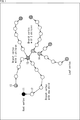
- circles indicate points and arrows indicate reference relationships.
- the method of forming this reference structure is arbitrary. For example, it is formed so that the geometry data of nearby points is referenced.
- point 11 (Root vertex) that does not refer to the geometry data of another point
- point 12 (Branch vertex with one child) that is referenced from another point
- point 13 (Branch vertex with 3 children) referenced
- point 14 (Branch vertex with 2 children) referenced by the other two points
- a point 15 (Leaf vertex) not referenced by the other points are formed.
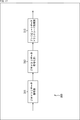
- the predicted value of the geometry data at each point is derived according to such a reference structure (prediction tree). For example, predicted values are derived by four methods (4 modes), and the optimum predicted value is selected from them.
- the point 24 is set as a processing target point (Target point pi) and a predicted value of the geometry data is derived.
- the point 23 (P parent ) to which the point 24 refers to (also referred to as the parent node) in such a reference structure is set as the predicted point 31 of the point 24, and the geometry data thereof is the geometry of the point 24.
- the geometry data of the prediction point 31 (that is, the prediction value of the geometry data of the point 24 in the first mode) is referred to as q (Delta).
- the inverse of the reference vector (arrow between the point 23 and the point 22) starting from the point 23 and ending at the point 22 (P grandparent) which is the parent node of the point 23.
- the start point of the vector is the point 23
- the end point of the inverse vector is the prediction point 32
- the geometry data is the prediction value of the geometry data at the point 24.
- the geometry data of the prediction point 32 (that is, the prediction value of the geometry data of the point 24 in the second mode) is referred to as q (Linear).
- a reference vector (arrow between the point 22 and the point 21) starting from the point 22 and ending at the point 21 (P great-grandparent) which is the parent node of the point 22.
- the start point of the inverse vector of is set to point 23
- the end point of the inverse vector is set to the prediction point 33
- the geometry data is set to the predicted value of the geometry data of point 24.
- the geometry data of the prediction point 33 (that is, the prediction value of the geometry data of the point 24 in the third mode) is referred to as q (Parallelogram).
- the point 24 is set as the root point (Root vertex), and the geometry data of other points is not referred to. That is, for this point 24, the geometry data at point 24 is encoded, not the predicted residuals. In the case of the reference structure of the example of FIG. 2, since the point 24 refers to the point 23, this mode is excluded.
- Predicted residuals are derived for the predicted values of each of the above modes (3 modes in the example of FIG. 2), and the minimum predicted residual is selected. That is, the nearest predicted point with respect to the point 24 is selected, and the predicted residual corresponding to the predicted point is selected.
- the predicted residual of each point is derived. Then, the predicted residual is encoded. By doing so, it is possible to suppress an increase in the amount of code.
- the reference structure (prediction tree) is formed based on a predetermined method, but this forming method is arbitrary. For example, assume that each point 41 is captured in the order shown in A of FIG. In FIG. 3, circles indicate points, and the numbers in the circles indicate the capture order. In FIG. 3, only the point 41 whose capture order is 0 is designated by a reference numeral, but all the circles in FIG. 3 are the points 41. That is, in FIG. 3, five points 41 whose capture order is from 0 to 5 are shown.
- a reference structure may be formed so that each point refers to the nearest point (as a parent node), for example, as shown in FIG. 3B.
- Encoding / decoding is performed according to the reference structure, and the child node (the node whose reference destination is the processing target node) is searched using the stack. Therefore, the decoding order in this case is point 41 where the capture order is "0", point 41 where the capture order is "1", point 41 where the capture order is "3", point 41 where the capture order is "4", and capture.
- the order is "5" point 41, and the capture order is "2" point 41.
- a reference structure may be formed so that each point refers to a point in the previous capture order (referred to as a parent node).
- the decoding order in this case is the same as the capture order.
- the bit rate of the coded data of the geometry data generated by the coding can be controlled. That is, it is possible to control the storage capacity when storing the coded data and the transmission rate when transmitting the coded data.
- the resolution also referred to as spatial resolution
- Such a decoding method is also referred to as scalable decoding (or decoding scalability). By realizing such scalable decoding, it is possible to omit the decoding process of unnecessary data, so that it is possible to suppress an increase in the load of the decoding process.
- the number of points can be reduced during transcoding, which is a process of decoding the coded data of geometry data, changing desired parameters, and re-encoding. By doing so, it is possible to suppress an increase in the transcoding load.
- the bit rate of the coded data of the geometry data generated by transcoding can be controlled.
- the predicted value of the node below that child node cannot be derived. That is, it is not possible to delete only the desired points regardless of this prediction tree (the points of the child nodes are also deleted). Therefore, when a certain point is deleted, a phenomenon may occur in which many points around the point are also deleted according to the structure of the prediction tree. In that case, for example, the distribution mode of the points changes significantly locally, and the shape of the object indicated by the point cloud is deformed (that is, the point cloud cannot correctly express the shape of the object). Was likely to occur.
- ⁇ Hierarchy of reference structure> Therefore, as shown in the top row of the table shown in FIG. 4, the predictive geometry coding is extended and shown in the second row from the top of the table shown in FIG. 4 (column "1").
- a group of points is formed, and a reference structure having the group as a hierarchy is formed.
- this hierarchy is referred to as a group hierarchy, and such a hierarchy of reference structures is referred to as a group hierarchy.
- a reference structure of geometry data in the coding of the point cloud which is layered by a group that classifies the points of the point cloud that expresses a three-dimensional object as a set of points, is formed, and the formed reference structure is formed.
- the predicted value of the geometry data is derived for each point, the predicted residual which is the difference between the geometry data and the predicted value is derived, and the predicted residual of the geometry data of the derived point is encoded. do.
- a reference structure of geometry data in the coding of the point cloud is formed, which is layered by a group that classifies the points of the point cloud that expresses a three-dimensional object as a set of points.
- the predicted value of the geometry data is derived for each point, and the predicted residual which is the difference between the geometry data and the predicted value is derived. It is provided with a predicted residual derivation unit and a coding unit that encodes the predicted residual of the geometry data of each point derived by the predicted residual derivation unit.
- the selection of points for each group hierarchy is in line with the prediction tree.
- points belonging to the lowest layer of this group hierarchy correspond to the node on the most leaf side (Leaf side) of the prediction tree, and points belonging to other group hierarchies are on the root side (Root side) of that node.
- the points belonging to the lower group hierarchy can be deleted without affecting the points belonging to the upper group hierarchy.
- the bit rate of the coded data of the geometry data generated by the coding can be controlled.
- each captured point is grouped and the group is grouped. You may sort (sort) each point in order.
- a reference structure layered by the group is formed. You may.
- a reference structure forming unit has a grouping processing unit that divides points into groups, a sorting unit that sorts the points by group, and each point in the order in which the points are sorted by the sorting unit.
- the group layered reference structure forming unit may be provided to form the reference structure layered by the group.
- These points 51 are grouped by a predetermined method. This grouping method is arbitrary. In the case of A in FIG. 5, the group is divided into a group of points 51 having an odd capture order (1, 3, 5, 7) and a group of points 51 having an even capture order (2, 4, 6, 8). There is.
- these points 51 are sorted by group.
- the point 51 is in the order of the point 51 group having an odd capture order (1, 3, 5, 7) and the point 51 group having an even capture order (2, 4, 6, 8). Are sorted.
- the reference destination of each point is obtained in this sorted order, and a prediction tree is formed.
- a prediction tree is formed.
- the node corresponding to the point 51 whose capture order is even is formed as a node on the leaf side (child node side) of the node corresponding to the point 51 whose capture order is odd. Therefore, even if the points 51 whose capture order is even are deleted, the points 51 whose capture order is odd are not affected.
- the points to be coded can be selected, so that the increase in the load of the coding process can be suppressed.
- the bit rate of the coded data of the geometry data generated by the coding can be controlled.
- the prediction tree By forming the prediction tree by such a method, after sorting, the prediction tree can be formed by the same method as that described in Non-Patent Document 2. Therefore, the prediction tree can be group-hierarchized more easily. As a result, it is possible to suppress an increase in the cost for forming the prediction tree.
- grouping As shown in the fourth column from the top of the table shown in FIG. 4 (column of "1-1-1"), grouping (grouping of points) is performed according to the position of the points. You may.
- the points belonging to each group may be grouped so that the density in the three-dimensional space is uniform (so that the points are spaced apart from each other).
- the number of points can be reduced so that the density of the encoded points becomes uniform. That is, it is necessary to suppress an increase in the load of the coding process or control the bit rate of the coded data so as to reduce the change in the distribution mode of the point cloud (that is, the shape of the object indicated by the point cloud). Can be done.
- the resolution (spatial resolution) on the three-dimensional space of the point cloud can be controlled by increasing or decreasing the number of group hierarchies in which points are deleted.
- grouping is performed according to the characteristics of the points. You may.
- the characteristics of the points used for this grouping are arbitrary. For example, it may be grouped by points corresponding to the edges and corners of the point cloud, or may be grouped by points corresponding to the flat part of the point cloud. Of course, the features may be other than these examples.
- points that have a relatively small subjective effect (characteristic) during reproduction are deleted, and points that have a relatively large subjective effect (characteristic) during reproduction are deleted.
- the grouping method is arbitrary and is not limited to these examples. For example, grouping may be performed according to both the position and characteristics of the points.
- layer information which is information about the group hierarchy may be signaled.
- layer information indicating the group hierarchy may be generated and encoded for each point.
- the reference structure forming unit further includes a layer information generating unit that generates layer information indicating a group hierarchy that is a hierarchy of groups in the reference structure for each point, and the coding unit further includes the layer information.
- the layer information generated by the generator may be further encoded.
- the group hierarchy may be indicated by the difference (relative value from the parent node) from the group hierarchy of the parent node.
- points 60 to 69 are captured as shown in A in FIG. Then, points 60, 63, 66, and 69 are divided into the first group, points 61, 64, and 67 are divided into the second group, and points 62, 65, and 68 are divided. Is divided into a third group. Then, it is assumed that these points are sorted for each group as described above, reference destinations are set, and a prediction tree as shown in B of FIG. 6 is formed.
- the point 61 belongs to the second group, and the parent node of the node corresponding to the point 61 in the prediction tree is the node corresponding to the point 60 belonging to the first group, so it corresponds to the point 61.
- "+1" is generated as layer information for the node to be used. This "+1" indicates that the node to be processed belongs to the group hierarchy (second group) one hierarchy lower than the group hierarchy (first group) of the parent node.
- the point 62 belongs to the third group and the parent node of the node corresponding to the point 62 in the prediction tree is the node corresponding to the point 61 belonging to the second group, the node corresponding to the point 62. For, "+1" is generated as layer information.
- the point 63 belongs to the first group, and the parent node of the node corresponding to the point 63 in the prediction tree is the node corresponding to the point 60 belonging to the same first group. For the corresponding node, "+0" is generated as layer information.
- the point 64 belongs to the second group, and the parent node of the node corresponding to the point 64 in the prediction tree is the node corresponding to the point 61 belonging to the same second group, so that the point 64 corresponds to the point 64. For the node, "+0" is generated as layer information.
- the point 65 belongs to the third group, and the parent node of the node corresponding to the point 65 in the prediction tree is the node corresponding to the point 62 belonging to the same third group, so that the point 65 corresponds to the point 65.
- "+0" is generated as layer information.
- the point 66 belongs to the first group, and the parent node of the node corresponding to the point 66 in the prediction tree is the node corresponding to the point 63 belonging to the same first group, so that the point 66 corresponds to the point 66.
- "+0" is generated as layer information.
- the point 67 belongs to the second group and the parent node of the node corresponding to the point 67 in the prediction tree is the node corresponding to the point 66 belonging to the first group, the node corresponding to the point 67 Generates "+1" as layer information.
- point 68 belongs to the third group and the parent node of the node corresponding to the point 68 in the prediction tree is the node corresponding to the point 65 belonging to the same third group, the node corresponding to the point 68 Therefore, "+0" is generated as the layer information.
- point 69 belongs to the first group, and the parent node of the node corresponding to the point 69 in the prediction tree is the node corresponding to the point 66 belonging to the same first group, so that it corresponds to the point 669. For the node, "+0" is generated as layer information.
- the group hierarchy of each point can be easily grasped on the decoding side based on the signaled layer information. Therefore, at the time of decoding, only the coded data of the desired group hierarchy can be decoded based on the layer information. That is, scalable decoding can be easily realized. In other words, since the decoding side can grasp the structure of the group hierarchy based on the layer information, the coding side can arbitrarily set the group.
- the group hierarchy to which the processing target node belongs as a relative value from the group hierarchy to which the parent node belongs as described above, it is possible to suppress an increase in the code amount due to this layer information.
- the layer information is signaled at the parent node as shown in the seventh stage from the top (stage of "1-2-1") in the table shown in FIG. You may try to do it.
- layer information indicating the group hierarchy of each child node belonging to the processing target node in the reference structure as a relative value to the group hierarchy of the processing target node may be generated and encoded.
- information indicating the group hierarchy of the child node is signaled.
- the layer information may be signaled at the child node.
- the layer information indicating the group hierarchy of the processing target node in the reference structure as a relative value to the group hierarchy of the parent node to which the processing target node belongs may be generated and encoded.
- information (+1) indicating the group hierarchy to which the node corresponding to the point 61 belongs is signaled as the layer information of the node corresponding to the point 61.
- information (+0) indicating the group hierarchy to which the node corresponding to the point 63 belongs is signaled.
- information indicating the group hierarchy of the node is signaled.
- Quantization may be performed when encoding various information such as geometry data (predicted residual).
- the quantization step may be controlled layer by layer as shown in the ninth stage (“1-3” stage) from the top of the table shown in FIG. That is, the predicted residual or the like may be quantized and encoded by a quantization step set for each group hierarchy, which is a hierarchy of groups in the reference structure. For example, the quantization step may be changed for each layer.
- the layer information may be signaled in the child node.
- the quantization step may be signaled. That is, the information indicating the quantization step may be encoded.
- FIG. 4 As shown in the eleventh stage (stage "1-4") from the top of the table shown in FIG. 4, when encoding various information such as geometry data (predicted residual), FIG. 4 As shown in the twelfth column (column of "1-4-1") from the top of the table shown in (1), arithmetic coding may be performed independently for each layer (group hierarchy). That is, the predicted residuals and the like may be arithmetically coded separately for each group hierarchy, which is a hierarchy of groups in the reference structure. By doing so, the coded data can be decoded for each group hierarchy. For example, when a part of the group hierarchy is deleted and transcoded, the transcoding can be performed only by selecting the coded data of the group hierarchy that is not deleted (without decoding). This makes it possible to suppress an increase in the transcoding load. In this case, the layer information may be signaled at the parent node.
- arithmetic coding may be performed independently in units smaller than the group hierarchy. For example, arithmetic coding may be performed independently for each branch or node of the prediction tree.
- the predicted residuals and the like may be arithmetically coded without being divided into group hierarchies, which are hierarchies by groups in the reference structure.
- arithmetic coding may be performed without dividing the predicted residuals of a plurality of group hierarchies.
- arithmetic coding may be performed without dividing the predicted residuals of all group hierarchies.
- whether or not to encode may be selected for each group hierarchy, and the predicted residuals of the group hierarchy selected to be encoded may be encoded. That is, control of whether or not to encode (control of whether or not to delete) may be performed for each group hierarchy.
- the coding control may be performed in units smaller than the group hierarchy. For example, whether or not to encode may be selected for each branch of the reference structure, and the predicted residuals of the nodes belonging to the branches selected to be encoded may be encoded. That is, control of whether or not to encode (control of whether or not to delete) may be performed for each branch. By doing so, the information of some branches in the group hierarchy can be deleted, and finer coding control can be realized.
- the information unit of this coding control is arbitrary, and of course, the coding control may be performed for each information unit other than the above-mentioned example. For example, it may be possible to perform coding control for each of a plurality of information units. For example, it may be possible to perform coding control for each group hierarchy or for each branch.
- FIG. 7 is a block diagram showing an example of a configuration of a coding device, which is an aspect of an information processing device to which the present technology is applied.
- the coding device 100 shown in FIG. 7 is a device that encodes a point cloud (3D data).
- the coding device 100 encodes the point cloud by applying the above-mentioned technology with reference to, for example, FIG.
- FIG. 7 shows the main things such as the processing unit and the data flow, and not all of them are shown in FIG. 7. That is, in the coding apparatus 100, there may be a processing unit that is not shown as a block in FIG. 7, or there may be a processing or data flow that is not shown as an arrow or the like in FIG. 7.
- the coding device 100 has a geometry data coding unit 111 and an attribute data coding unit 112.
- the geometry data coding unit 111 acquires the point cloud (3D data) input to the coding device 100, encodes the geometry data (position information), generates the coded data of the geometry data, and generates it.
- the coded data of the geometry data and the attribute data (attribute information) are supplied to the attribute data coding unit 112.
- the attribute data coding unit 112 acquires the coding data and the attribute data of the geometry data supplied from the geometry data coding unit 111, encodes the attribute data using them, and encodes the attribute data. Is generated, and the coded data of the geometry data and the coded data of the generated attribute data are output to the outside of the coding device 100 (for example, the decoding side) as the coded data of the point cloud data.
- each processing unit may be configured by a logic circuit that realizes the above-mentioned processing.
- each processing unit has, for example, a CPU (Central Processing Unit), a ROM (Read Only Memory), a RAM (Random Access Memory), and the like, and the above-mentioned processing is realized by executing a program using them. You may do so.
- each processing unit may have both configurations, and a part of the above-mentioned processing may be realized by a logic circuit, and the other may be realized by executing a program.
- the configurations of the respective processing units may be independent of each other.
- some processing units realize a part of the above-mentioned processing by a logic circuit, and some other processing units execute a program.
- the above processing may be realized, and another processing unit may realize the above-mentioned processing by both the logic circuit and the execution of the program.
- FIG. 8 is a block diagram showing a main configuration example of the geometry data coding unit 111. It should be noted that FIG. 8 shows the main things such as the processing unit and the flow of data, and not all of them are shown in FIG. That is, in the geometry data coding unit 111, there may be a processing unit that is not shown as a block in FIG. 8, or there may be a processing or data flow that is not shown as an arrow or the like in FIG.
- the geometry data coding unit 111 includes a reference structure forming unit 131, a stack 132, a prediction mode determination unit 133, a coding unit 134, and a prediction point generation unit 135.
- the geometry data of the point cloud data supplied to the geometry data coding unit 111 is supplied to the reference structure forming unit 131.
- the attribute data is not processed by the geometry data coding unit 111, but is supplied to the attribute data coding unit 112.
- the reference structure forming unit 131 generates a reference structure (prediction tree) in point cloud coding for the supplied geometry data. At that time, the reference structure forming unit 131 may form a group-layered reference structure by applying various methods as described above with reference to the table of FIG. Further, the reference structure forming unit 131 generates layer information indicating the formed reference structure for each point. The reference structure forming unit 131 supplies the geometry data, layer information, and the like of the processing target point to the stack 132 according to the formed reference structure. At that time, the reference structure forming unit 131 may apply various methods as described above with reference to the table of FIG.
- the reference structure forming unit 131 determines whether or not to encode the child node in the reference structure (prediction tree) formed by the reference structure forming unit 131 according to the coding control by the user or the like, and encodes the child node. If it is determined to be so, the geometry data, layer information, and the like of the child nodes of the processing target node may be supplied to the stack 132. For example, the reference structure forming unit 131 may select whether or not to encode the predicted residual or the like for each group hierarchy, and supply the predicted residual or the like of the nodes belonging to the group hierarchy to the stack 132.
- the reference structure forming unit 131 may select whether or not to encode the predicted residual or the like for each branch of the reference structure, and supply the predicted residual or the like of the node belonging to the branch to the stack 132. By doing so, the geometry data can be encoded only for some points.
- the stack 132 holds information in a last-in, first-out manner.
- the stack 132 holds the geometry data, layer information, and the like of each point supplied from the reference structure forming unit 131. Further, the stack 132 supplies the last held information among the held information to the prediction mode determination unit 133 in response to the request from the prediction mode determination unit 133.
- the prediction mode determination unit 133 performs processing related to determination of the prediction mode (prediction point). For example, the prediction mode determination unit 133 acquires the geometry data, layer information, and the like of the point last held in the stack 132. Further, the prediction mode determination unit 133 acquires the geometry data and the like of the prediction point of the point from the prediction point generation unit 135. When there are a plurality of prediction points corresponding to the processing target points as in the example of FIG. 2, all of them are acquired. Then, the prediction mode determination unit 133 determines the prediction point (that is, the prediction mode) to be applied. At that time, the prediction mode determination unit 133 may apply various methods as described above with reference to the table of FIG.
- the prediction mode determination unit 133 derives a prediction residual, which is the difference between the geometry data (prediction value) and the geometry data of the processing target point, for each prediction point, and compares the values. By such comparison, the prediction mode (prediction method) to be applied is selected. For example, the predicted point closest to the processing target point is selected.
- the prediction mode determination unit 133 supplies information about each point (for example, prediction residuals of the selected prediction mode, layer information, etc.) to the coding unit 134.
- the coding unit 134 acquires the information supplied by the prediction mode determination unit 133 (for example, the prediction residual of the selected prediction mode, the layer information, etc.), encodes it, and generates the coded data.
- the prediction mode determination unit 133 for example, the prediction residual of the selected prediction mode, the layer information, etc.
- the coding unit 134 may apply various methods as described above with reference to the table of FIG.
- the coding unit 134 can be quantized and coded in a quantization step set for each group hierarchy.
- the coding unit 134 can encode and signal the information indicating the quantization step.
- the coding unit 134 can perform arithmetic coding by dividing the predicted residuals and the like into each group hierarchy, or can perform arithmetic coding without dividing into each group hierarchy.
- the coding unit 134 supplies the generated coding data to the attribute data coding unit 112 as the coding data of the geometry data. Further, the coding unit 134 supplies information such as geometry data of the processing target point to the prediction point generation unit 135.
- the prediction point generation unit 135 performs processing related to generation of prediction points, that is, derivation of prediction values. For example, the prediction point generation unit 135 acquires information such as geometry data of the processing target point supplied from the coding unit 134. Further, the prediction point generation unit 135 derives the geometry data of the prediction point that can be generated using the geometry data of the processing target point (for example, the prediction value of the geometry data of the child node of the processing target node). At that time, the prediction point generation unit 135 may apply various methods as described above with reference to the table of FIG. The prediction point generation unit 135 supplies the derived predicted value to the prediction mode determination unit 133 as needed.
- FIG. 9 is a block diagram showing a main configuration example of the reference structure forming unit 131. It should be noted that FIG. 9 shows the main things such as the processing unit and the flow of data, and not all of them are shown in FIG. That is, in the reference structure forming unit 131, there may be a processing unit that is not shown as a block in FIG. 9, or there may be a processing or data flow that is not shown as an arrow or the like in FIG.
- the reference structure forming unit 131 includes a grouping processing unit 151, a sorting unit 152, a group layered reference structure forming unit 153, and a layer information generation unit 154.
- the grouping processing unit 151 performs processing related to grouping. For example, the grouping processing unit 151 groups the points of the geometry data supplied to the reference structure forming unit 131. At that time, the grouping processing unit 151 may apply various methods as described above with reference to the table of FIG. For example, the grouping processing unit 151 may perform grouping according to the position of the point. Further, the grouping processing unit 151 may perform the grouping according to the characteristics of the points. The grouping processing unit 151 supplies the geometry data of each grouped point to the sorting unit 152.
- the sort unit 152 performs processing related to sorting points. For example, the sort unit 152 acquires the geometry data of each grouped point supplied by the grouping processing unit 151. Then, the sort unit 152 sorts the geometry data at each point. At that time, the sort unit 152 may apply various methods as described above with reference to the table of FIG. For example, the sorting unit 152 sorts the geometry data of each point grouped by the grouping processing unit 151 so as to be grouped into each group. The sort unit 152 supplies the geometry data of each sorted point to the group layered reference structure forming unit 153.
- the group layered reference structure forming unit 153 performs processing related to the formation of the reference structure. For example, the group layered reference structure forming unit 153 acquires the geometry data of each sorted point supplied from the sorting unit 152. The group layered reference structure forming unit 153 forms a reference structure. At that time, the group layered reference structure forming unit 153 may apply various methods as described above with reference to the table of FIG. For example, the group layered reference structure forming unit 153 forms a group layered reference structure by setting the reference destination of each point according to the sorted order supplied from the sort unit 152. The method of forming this reference structure is arbitrary. The group layered reference structure forming unit 153 supplies the reference structure thus formed to the layer information generation unit 154.
- the layer information generation unit 154 acquires the reference structure supplied from the group layered reference structure forming unit 153.
- the layer information generation unit 154 generates layer information indicating the reference structure thereof.
- the layer information generation unit 154 may apply various methods as described above with reference to the table of FIG.
- the layer information generation unit 154 generates information indicating the group hierarchy of each child node belonging to the processing target node in the reference structure (for example, a value relative to the group hierarchy of the processing target node) as the layer information of the processing target node. , May be signaled.
- the layer information generation unit 154 generates information indicating the group hierarchy of the processing target node in the reference structure (for example, a relative value with the group hierarchy of the parent node to which the processing target node belongs) as the layer information of the processing target node. It may be signaled.
- the layer information generation unit 154 supplies the generated layer information to the stack 132 (FIG. 8).
- the coding device 100 can make the reference structure of the geometry data into a group hierarchy. Therefore, as described above, the coding apparatus 100 can suppress an increase in the load of the coding process. In addition, the bit rate of the coded data of the geometry data generated by the coding can be controlled. In addition, it is possible to control the storage capacity when storing the coded data and the transmission rate when transmitting the coded data.
- the coding device 100 encodes the data in the point cloud by executing the coding process. An example of the flow of this coding process will be described with reference to the flowchart of FIG.
- the geometry data coding unit 111 of the coding apparatus 100 encodes the input point cloud geometry data by executing the geometry data coding process in step S101, and the geometry Data encoding Generate data.
- step S102 the attribute data coding unit 112 encodes the input point cloud attribute data and generates the coded data of the attribute data.
- step S102 When the process of step S102 is completed, the coding process is completed.
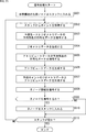
- the reference structure forming unit 131 executes the reference structure forming process in step S131 to form the reference structure (prediction tree) of the geometry data.
- the reference structure forming unit 131 also generates layer information corresponding to the formed reference structure.
- step S132 the reference structure forming unit 131 stores the geometry data and the like of the head node of the reference structure formed in step S131 in the stack 132.
- step S133 the prediction mode determination unit 133 acquires the geometry data of the last stored point (node) from the stack 132.
- step S134 the prediction mode determination unit 133 sets the point for which information was acquired in step S133 as the processing target, derives the prediction residual of the geometry data for the processing target point, and determines the prediction mode.
- step S135 the coding unit 134 encodes the prediction mode determined in step S134. Further, in step S136, the coding unit 134 encodes the prediction residual of the geometry data in the prediction mode determined in step S134. Further, in step S137, the coding unit 134 encodes the child node information indicating whether the child node of the processing target node is a degree node. Further, in step S138, the coding unit 134 encodes the layer information generated in step S131. The coding unit 134 supplies the coding data of these information to the attribute data coding unit 112 as the coding data of the geometry data.
- step S139 the reference structure forming unit 131 determines whether or not to encode the child node of the processing target node based on the coding control by the user or the like. If it is determined to be encoded, the process proceeds to step S140.
- step S140 the reference structure forming unit 131 stores the geometry data and the like of its child nodes in the stack 132.
- the process of step S140 proceeds to step S141. If it is determined in step S139 that the child node is not encoded, the process of step S140 is skipped and the process proceeds to step S141.
- step S141 the prediction point generation unit 135 generates the geometry data of the prediction point that can be generated using the geometry data of the processing target point.
- step S142 the prediction mode determination unit 133 determines whether or not the stack 132 is empty. If it is determined that the stack 132 is not empty (that is, the information of at least one point is stored), the process returns to step S133. That is, the processing of steps S133 to S142 is executed with the point finally stored in the stack 132 as the processing target.
- step S142 the geometry data coding process is completed and the process returns to FIG.
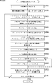
- the grouping process unit 151 groups each point of the point cloud in step S161.
- step S162 the sort unit 152 sorts the processing order of each point of the point cloud so as to line up for each group set in step S161.
- step S163 the group layered reference structure forming unit 153 forms a group layered reference structure by forming reference destinations for each point in the order sorted in step S163.
- step S164 the layer information generation unit 154 forms the layer information of each point.
- step S164 When the process of step S164 is completed, the reference structure forming process is completed, and the process returns to FIG.
- the coding apparatus 100 can group-layer the reference structure of the geometry data. Therefore, as described above, the coding apparatus 100 can suppress an increase in the load of the coding process. In addition, the bit rate of the coded data of the geometry data generated by the coding can be controlled. In addition, it is possible to control the storage capacity when storing the coded data and the transmission rate when transmitting the coded data.
- FIG. 13 is a block diagram showing an example of a configuration of a decoding device, which is an aspect of an information processing device to which the present technology is applied.
- the decoding device 200 shown in FIG. 13 is a device that decodes the coded data of the point cloud (3D data).
- the decoding device 200 decodes, for example, the coded data of the point cloud generated in the coding device 100.
- FIG. 13 shows the main things such as the processing unit and the flow of data, and not all of them are shown in FIG. That is, in the decoding device 200, there may be a processing unit that is not shown as a block in FIG. 13, or there may be a processing or data flow that is not shown as an arrow or the like in FIG.
- the decoding device 200 has a geometry data decoding unit 211 and an attribute data decoding unit 212.
- the geometry data decoding unit 211 acquires the coded data of the point cloud (3D data) input to the coding device 100, decodes the coded data of the geometry data, generates the geometry data, and generates the generated geometry.
- the data and the coded data of the attribute data are supplied to the attribute data decoding unit 212.
- the attribute data decoding unit 212 acquires the geometry data supplied from the geometry data decoding unit 211 and the coded data of the attribute data. Further, the attribute data decoding unit 212 decodes the coded data of the attribute data using the geometry data to generate the attribute data, and the geometry data and the generated attribute data are used as point cloud data in the decoding device 200. Output to the outside.
- each processing unit may be configured by a logic circuit that realizes the above-mentioned processing.
- each processing unit may have, for example, a CPU, ROM, RAM, etc., and execute a program using them to realize the above-mentioned processing.
- each processing unit may have both configurations, and a part of the above-mentioned processing may be realized by a logic circuit, and the other may be realized by executing a program.
- the configurations of the respective processing units may be independent of each other.
- some processing units realize a part of the above-mentioned processing by a logic circuit, and some other processing units execute a program.
- the above processing may be realized, and another processing unit may realize the above-mentioned processing by both the logic circuit and the execution of the program.
- FIG. 14 is a block diagram showing a main configuration example of the geometry data decoding unit 211. It should be noted that FIG. 14 shows the main things such as the processing unit and the flow of data, and not all of them are shown in FIG. That is, in the geometry data decoding unit 211, there may be a processing unit that is not shown as a block in FIG. 14, or there may be a processing or data flow that is not shown as an arrow or the like in FIG.
- the geometry data decoding unit 211 has a storage unit 231, a stack 232, a decoding unit 233, a geometry data generation unit 234, and a prediction point generation unit 235.
- the coded data of the geometry data supplied to the geometry data decoding unit 211 is supplied to the storage unit 231.
- the coded data of the attribute data is not processed by the geometry data decoding unit 211, but is supplied to the attribute data decoding unit 212.
- the storage unit 231 stores the encoded data of the geometry data supplied to the geometry data decoding unit 211. Further, the storage unit 231 supplies the coded data of the geometry data of the point to be decoded to the stack 232 under the control of the decoding unit 233. At that time, the storage unit 231 may apply various methods as described above with reference to the table of FIG.
- Stack 232 holds information in a last-in, first-out manner. For example, the stack 232 holds the coded data of each point supplied from the storage unit 231. Further, the stack 232 supplies the last held information among the held information to the decoding unit 233 in response to the request from the decoding unit 233.
- the decoding unit 233 performs processing related to decoding the coded data of the geometry data. For example, the decoding unit 233 acquires the coded data of the point last held in the stack 232. Further, the decoding unit 233 decodes the acquired coded data and generates geometry data (predicted residual, etc.). At that time, the decoding unit 233 may apply various methods as described above with reference to the table of FIG. The decoding unit 233 supplies the generated geometry data (predicted residuals, etc.) to the geometry data generation unit 234.
- the decoding unit 233 can perform decoding control so as to decode only a part of the coded data requested by, for example, a user or the like. For example, the decoding unit 233 can control whether or not to decode for each group hierarchy. Further, the decoding unit 233 can control whether or not to decode each branch of the reference structure. Then, the decoding unit 233 can control the storage unit 231 and store only the coded data of the point to be decoded in the stack 232. With such decoding control, the decoding unit 233 can realize scalable decoding of geometry data.
- the decoding unit 233 is hierarchized by the group in the reference structure of the geometry data in the coding of the point cloud, which is hierarchized by the group that classifies the points of the point cloud that expresses the object of the three-dimensional shape as a set of points.
- the coded data corresponding to the hierarchy may be decoded.
- Geometry data generation unit 234 performs processing related to geometry data generation. For example, the geometry data generation unit 234 acquires information such as a predicted residual supplied from the decoding unit 233. Further, the geometry data generation unit 234 acquires a prediction point corresponding to the processing target point (that is, a predicted value of the geometry data of the processing target point) from the prediction point generation unit 235. Then, the geometry data generation unit 234 generates the geometry data of the processing target point by using the acquired predicted residual and the predicted value (for example, adding both). The geometry data generation unit 234 supplies the generated geometry data to the attribute data decoding unit 212.
- the geometry data generation unit 234 acquires information such as a predicted residual supplied from the decoding unit 233. Further, the geometry data generation unit 234 acquires a prediction point corresponding to the processing target point (that is, a predicted value of the geometry data of the processing target point) from the prediction point generation unit 235. Then, the geometry data generation unit 234 generates the geometry data of the processing target point by using the acquired predicted residual
- the prediction point generation unit 235 performs processing related to generation of prediction points, that is, derivation of prediction values. For example, the prediction point generation unit 235 acquires information such as geometry data of the processing target point generated by the geometry data generation unit 234. Further, the prediction point generation unit 235 derives the geometry data of the prediction point that can be generated using the geometry data of the processing target point (for example, the prediction value of the geometry data of the child node of the processing target node). At that time, the prediction point generation unit 235 may apply various methods as described above with reference to the table of FIG. For example, the prediction point generation unit 235 can generate prediction points in the same manner as in the case of the prediction point generation unit 135 of the coding device 100. The prediction point generation unit 235 supplies the derived predicted value to the geometry data generation unit 234 as needed.
- the decoding device 200 can decode the coded data using the grouped reference structure of the geometry data. Therefore, as described above, the decoding device 200 can realize scalable decoding and suppress an increase in the load of the decoding process.
- the decoding device 200 decodes the coded data of the point cloud by executing the decoding process.
- An example of the flow of the decoding process will be described with reference to the flowchart of FIG.
- the geometry data decoding unit 211 of the decoding device 200 decodes the input coded data of the input point cloud geometry data by executing the geometry data decoding process in step S201, and the geometry is decoded. Generate data.
- step S202 the attribute data decoding unit 212 encodes the coded data of the input point cloud attribute data and generates the attribute data.
- step S202 When the process of step S202 is completed, the decryption process is completed.
- the storage unit 231 stores the coded data of the supplied geometry data, and in step S231, the coded data of the first node of the reference structure (prediction tree) of the geometry data. Is stored in the stack 232.
- step S232 the decoding unit 233 acquires the coded data of the last stored point (node) from the stack 232.
- step S233 the decoding unit 233 decodes the coded data acquired in step S232 and generates layer information. Further, in step S234, the decoding unit 233 decodes the coded data acquired in step S232 and generates a prediction residual of the prediction mode and the geometry data.
- step S235 the geometry data generation unit 234 generates geometry data of the processing target node using the predicted residual generated in step S234 and the predicted value of the processing target node (for example, adding both). ..
- step S236 the prediction point generation unit 235 generates geometry data (that is, prediction value) of prediction points that can be generated using the geometry data of the processing target node.
- step S237 the decoding unit 233 decodes the coded data acquired in step S232 and generates child node information.
- step S238 the decoding unit 233 determines whether or not the child node is also decoded based on the child node information, the layer information, and the like according to the decoding control of the user or the like. If it is determined that the child node is also decoded, the process proceeds to step S239.
- step S239 the decoding unit 233 controls the storage unit 231 and stores the coded data of its child node in the stack 232.
- step S240 the process of step S239 is skipped and the process proceeds to step S240.
- step S240 the decoding unit 233 determines whether or not the stack 232 is empty. If it is determined that the stack 232 is not empty (that is, the information of at least one point is stored), the process returns to step S232. That is, the process of step S232 x to step S240 is executed with the point finally stored in the stack 232 as the processing target.
- step S240 the geometry data decoding process is completed and the process returns to FIG.
- the decoding device 200 can decode the coded data using the grouped reference structure of the geometry data. Therefore, as described above, the decoding device 200 can realize scalable decoding and suppress an increase in the load of the decoding process.
- FIG. 17 is a block diagram showing an example of a configuration of a transcoder, which is one aspect of an information processing apparatus to which the present technology is applied.
- the transcoder 300 shown in FIG. 17 is a device that decodes the coded data of the point cloud (3D data) and re-codes it by performing, for example, parameter conversion.
- the transcoder 300 transcodes (decodes / encodes) the coded data of the point cloud generated in the coding device 100, for example.
- FIG. 17 shows the main things such as the processing unit and the data flow, and not all of them are shown in FIG. That is, in the transcoder 300, there may be a processing unit that is not shown as a block in FIG. 17, or there may be a processing or data flow that is not shown as an arrow or the like in FIG.
- the transcoder 300 has a geometry data decoding unit 311, a geometry data coding unit 312, and an attribute data transcoding unit 313.
- the geometry data decoding unit 311 acquires the coded data of the point cloud data input to the transcoder 300.
- the geometry data decoding unit 311 decodes the coded data and generates the geometry data.
- the geometry data decoding unit 311 may apply various methods as described above with reference to the table of FIG.
- the geometry data decoding unit 311 may have the same configuration as the geometry data decoding unit 211 of the decoding device 200, and may perform the same processing. That is, the geometry data decoding unit 311 may realize scalable decoding.
- the geometry data decoding unit 311 supplies the coded data of the attribute data and the generated geometry data to the geometry data coding unit 312.
- the geometry data coding unit 312 acquires the coded data and the geometry data of the attribute data supplied from the geometry data decoding unit 311.
- the geometry data coding unit 312 re-encodes the geometry data and generates the coded data of the geometry data.
- the geometry data coding unit 312 may apply various methods as described above with reference to the table of FIG.
- the geometry data coding unit 312 may have the same configuration as the geometry data coding unit 111 of the coding device 100, and may perform the same processing. That is, the geometry data coding unit 312 may group-layer the reference structure of the geometry data. Further, after the reference structure is determined, the geometry data coding unit 312 can reduce the number of points and perform coding.
- the geometry data coding unit 312 may be able to control the bit rate of the coded data to be generated.
- the geometry data coding unit 312 supplies the coded data of the attribute data and the coded data of the generated geometry data to the attribute data transcoding processing unit 313.
- the geometry data parameters such as reduction of the number of points may be changed by the geometry data decoding unit 311 (performed by scalable decoding) or by the geometry data coding unit 312. It may be done in both of them.
- the attribute data transcoding processing unit 313 performs processing related to transcoding of attribute data. For example, the attribute data transcoding processing unit 313 acquires the coded data of the geometry data supplied from the geometry data coding unit 312 and the coded data of the attribute data. Further, the attribute data transcoding processing unit 313 decodes (transcodes) the coded data of the acquired attribute data by a predetermined method. The attribute data transcoding processing unit 313 outputs the coded data of the geometry data and the coded data of the generated attribute data as a transcoding result to the outside of the transcoder 300.
- the transcoder 300 can reduce the number of points during transcoding. That is, the transcoder 300 can suppress an increase in the load of the transcode. Further, the transcoder 300 can control the bit rate of the coded data of the geometry data generated by transcoding.
- each processing unit may be configured by a logic circuit that realizes the above-mentioned processing.
- each processing unit may have, for example, a CPU, ROM, RAM, etc., and execute a program using them to realize the above-mentioned processing.
- each processing unit may have both configurations, and a part of the above-mentioned processing may be realized by a logic circuit, and the other may be realized by executing a program.
- the configurations of the respective processing units may be independent of each other.
- some processing units realize a part of the above-mentioned processing by a logic circuit, and some other processing units execute a program.
- the above processing may be realized, and another processing unit may realize the above-mentioned processing by both the logic circuit and the execution of the program.
- Transcoding process flow Next, the processing executed by the transcoder 300 will be described.
- the transcoder 300 transcodes the coded data of the point cloud by executing the transcoding process. An example of the flow of this transcoding process will be described with reference to the flowchart of FIG.
- the geometry data decoding unit 311 of the transcoder 300 decodes the coded data and generates the geometry data by executing the geometry data decoding process in step S301.
- the geometry data decoding unit 311 can perform this geometry data decoding process in the same flow as the geometry data decoding process described with reference to the flowchart of FIG.
- the geometry data coding unit 312 encodes the geometry data by executing the geometry data coding process, and generates the coded data.
- the geometry data coding unit 312 can perform this geometry data coding process in the same flow as the geometry data coding process described with reference to the flowchart of FIG.
- step S303 the attribute data transcoding processing unit 313 transcodes the attribute data.
- the transcoding process is completed.
- the transcoder 300 can reduce the number of points at the time of transcoding. That is, the transcoder 300 can suppress an increase in the load of the transcode. Further, the transcoder 300 can control the bit rate of the coded data of the geometry data generated by transcoding.
- Second Embodiment> ⁇ Predicted residual coding of attribute data>
- the predictive geometry coding has been extended and shown in the second row from the top of the table shown in FIG. 19 (column "2"). As such, apply predictive geometry coding to the encoding of attribute data.
- a reference structure of attribute data in the encoding of a point cloud that expresses a three-dimensional object as a set of points is formed, and a predicted value of attribute data is derived for each point based on the formed reference structure.
- the predicted residual which is the difference between the attribute data and the predicted value is derived, and the predicted residual of the attribute data of each derived point is encoded.
- a reference structure forming unit that forms a reference structure for attribute data in point cloud coding that expresses a three-dimensional object as a set of points, and a reference structure formed by the reference structure forming unit. Based on, the predicted residual value of the attribute data is derived for each point, and the predicted residual that is the difference between the attribute data and the predicted value is derived. It is provided with a coding unit that encodes the predicted residual of the attribute data of each point.
- the reference structure of the attribute data in that case is 4 from the top of the table shown in FIG.
- the reference structure may be shared between the geometry data and the attribute data.
- the reference structure applied in predictive geometry coding may also be applied to coding of attribute data.
- by sharing the reference structure between the geometry data and the attribute data it is possible to perform scalable decoding of the point cloud data (geometry data and attribute data). Therefore, it is possible to suppress an increase in the load of the decoding process. It also enables lower latency decoding.
- the reference structure may be formed based on the geometry data, the reference structure may be formed based on the attribute data, or the geometry data may be formed.
- the reference structure may be formed based on both the and attribute data.
- the reference structure of all or part of the attribute data is referred to as the reference structure of the geometry data. It may be formed independently.
- the parameters related to the color (RGB) of the attribute data may have a reference structure common to the geometry data, and the parameters such as the reflectance of the attribute data may be formed independently of the reference structure of the geometry data.
- the attribute data of the prediction points of the processing target nodes are obtained from the top of the table shown in FIG. As shown in the 7th stage (stage of "2-2-1"), it may be the same as the attribute data of the parent node of the processing target node.
- the attribute data of the prediction point of the processing target node is used as the parent node of the processing target node. It may be the average of the attribute data of the parent node and the attribute data of its parent node.
- the attribute data of the prediction point of the processing target node is used as the parent node of the processing target node.
- the weighted average of the attribute data of and the attribute data of its parent node may be weighted by the reciprocal of the distance between the points corresponding to those nodes.
- the attribute data of the prediction point of the processing target node is input to the k node in the vicinity of the decoded node. It may be the average of the attribute data of.
- the prediction point that minimizes the prediction residual of the geometry data may be selected.
- the prediction point that minimizes the prediction residual of the attribute data is selected. May be good.
- the evaluation function f is the predicted residual of each variable of the geometry data (x coordinate, y coordinate, z coordinate) and each variable of the attribute data (color, reflectance, etc.).
- the variables in () may be used, and the prediction points may be selected based on the total predicted residuals of those variables.
- diff [variable name] indicates the predicted residual of each variable.
- the prediction mode can be selected by considering not only the position but also each variable of the attribute data, so that the encoding / decoding is adapted to not only the geometry data but also the characteristics of the attribute data. It can be performed. For example, if there are many variables in the attribute data (in many dimensions), or if the range of variables in the attribute data is larger than the variables in the geometry data, the dependency on the variables in the geometry data is reduced (in other words, the attributes). The prediction mode can be selected to improve the dependence of the data on variables).
- FIG. 20 is a block diagram showing an example of a configuration of a coding device, which is an aspect of an information processing device to which the present technology is applied.
- the coding device 400 shown in FIG. 20 is a device that encodes a point cloud (3D data), similarly to the coding device 100.
- the coding device 400 encodes the point cloud by applying the above-mentioned technology with reference to, for example, FIG.
- FIG. 20 shows the main things such as the processing unit and the data flow, and not all of them are shown in FIG. 20. That is, in the coding apparatus 400, there may be a processing unit that is not shown as a block in FIG. 20, or there may be a processing or data flow that is not shown as an arrow or the like in FIG. 20.
- the coding device 400 has a reference structure forming unit 411, a stack 412, a prediction mode determination unit 413, a coding unit 414, and a prediction point generation unit 415.
- the point cloud data (geometry data and attribute data) supplied to the coding device 400 is supplied to the reference structure forming unit 411.
- the reference structure forming unit 411 generates a reference structure (prediction tree) in point cloud coding for both the supplied geometry data and attribute data. At that time, the reference structure forming unit 411 can form the reference structure by applying various methods as described above with reference to the table of FIG. For example, the reference structure forming unit 411 can form a common reference structure between the geometry data and the attribute data. Further, the reference structure forming unit 411 can form the reference structure of the geometry data and the reference structure of the attribute data independently of each other. The reference structure forming unit 411 supplies the geometry data and the attribute data of the processing target point to the stack 412 according to the formed reference structure.
- a reference structure prediction tree
- Stack 412 holds information in a last-in, first-out manner. For example, the stack 412 holds the information of each point supplied from the reference structure forming unit 131. Further, the stack 412 supplies the last held information among the held information to the prediction mode determination unit 413 in response to the request from the prediction mode determination unit 413. The stack 412 can perform these processes for both geometry data and attribute data.
- the prediction mode determination unit 413 performs processing related to determination of the prediction mode (prediction point). For example, the prediction mode determination unit 413 acquires information on the last point held in the stack 412. Further, the prediction mode determination unit 413 acquires information on the prediction point of the point (that is, the prediction value of the processing target point) and the like from the prediction point generation unit 415. When there are a plurality of prediction points corresponding to the processing target points as in the example of FIG. 2, all of them are acquired. Then, the prediction mode determination unit 413 determines the prediction point (that is, the prediction mode) to be applied.
- the prediction mode determination unit 413 can perform such processing for both geometry data and attribute data. Further, the prediction mode determination unit 413 may apply various methods as described above with reference to the table of FIG. 19 during the processing.
- the prediction mode determination unit 413 can select a prediction point (prediction mode) that minimizes the prediction residual of the geometry data. Further, the prediction mode determination unit 413 can select a prediction point (prediction mode) that minimizes the prediction residual of the attribute data. Further, the prediction mode determination unit 413 can select a prediction point (prediction mode) that minimizes the prediction residual of the geometry data and the attribute data.
- the prediction mode determination unit 413 supplies information about each point (for example, the prediction residual of the geometry data and attribute data of the selected prediction mode) to the coding unit 414.
- the coding unit 414 acquires the information supplied by the prediction mode determination unit 413 (for example, the prediction residual of the selected prediction mode, etc.), encodes it, and generates the coded data.
- the coding unit 414 can perform such processing on both the geometry data and the attribute data.
- the coding unit 414 supplies the generated coded data as coded data of geometry data and attribute data to the outside of the coding device 400 (for example, the decoding side). Further, the coding unit 414 supplies the geometry data and the attribute data of the processing target point to the prediction point generation unit 415.
- the prediction point generation unit 415 performs processing related to generation of prediction points, that is, derivation of prediction values. For example, the prediction point generation unit 415 acquires information such as geometry data and attribute data of the processing target point supplied from the coding unit 414. Further, the prediction point generation unit 415 can generate geometry data or attribute data of the prediction point using the geometry data or attribute data of the processing target point (for example, geometry data or attribute data of a child node of the processing target node). Predicted value) is derived. At that time, the prediction point generation unit 415 may apply various methods as described above with reference to the table of FIG. The prediction point generation unit 415 supplies the derived predicted value to the prediction mode determination unit 413 as needed.
- the coding device 400 can encode the attribute data by the same method as the predictive geometry coding. Therefore, the coding device 400 can obtain the same effect as that of the geometry data in coding the attribute data. For example, since the predicted residual is encoded, the coding apparatus 400 can suppress an increase in the code amount of the coded data of the attribute data. In addition, the coding apparatus 400 can control the storage capacity when storing the coded data and the transmission rate when transmitting the coded data. That is, the coding device 400 can control the coding data bit rate of the attribute data.
- each processing unit may be configured by a logic circuit that realizes the above-mentioned processing.
- each processing unit may have, for example, a CPU, ROM, RAM, etc., and execute a program using them to realize the above-mentioned processing.
- each processing unit may have both configurations, and a part of the above-mentioned processing may be realized by a logic circuit, and the other may be realized by executing a program.
- the configurations of the respective processing units may be independent of each other. For example, some processing units realize a part of the above-mentioned processing by a logic circuit, and some other processing units execute a program.
- the above processing may be realized, and another processing unit may realize the above-mentioned processing by both the logic circuit and the execution of the program.
- the coding device 400 encodes the data in the point cloud by executing the coding process. An example of the flow of this coding process will be described with reference to the flowchart of FIG.
- the reference structure forming unit 411 executes the reference structure forming process in step S401 to form a reference structure (prediction tree) of the geometry data and the attribute data.
- the reference structure forming unit 411 can form the reference structure by the same method as that described in Non-Patent Document 2, for example.
- step S402 the reference structure forming unit 411 stores the geometry data, attribute data, etc. of the head node of the reference structure formed in step S401 in the stack 412.
- step S403 the prediction mode determination unit 413 acquires the geometry data, attribute data, etc. of the last stored point (node) from the stack 412.
- step S404 the prediction mode determination unit 413 targets the point for which information was acquired in step S403 as the processing target, derives the prediction residual of the geometry data for the processing target point, and determines the prediction mode.
- step S405 the coding unit 414 encodes the prediction mode determined in step S404. Further, in step S406, the coding unit 414 encodes the prediction residual of the geometry data in the prediction mode determined in step S404.
- step S407 the prediction mode determination unit 413 performs recolor processing and derives the prediction residual of the attribute data.
- the coding unit 414 encodes the predicted residuals of the attribute data.
- step S409 the coding unit 414 encodes the child node information indicating which node the child node of the processing target node is.
- step S410 the reference structure forming unit 411 determines whether or not to encode the child node of the processing target node based on the coding control by the user or the like. If it is determined to be encoded, the process proceeds to step S411.
- step S411 the reference structure forming unit 411 stores the geometry data and the like of its child nodes in the stack 412. When the process of step S411 is completed, the process proceeds to step S412. If it is determined in step S410 that the child node is not encoded, the process of step S411 is skipped and the process proceeds to step S412.
- step S412 the prediction point generation unit 415 generates geometry data and attribute data of prediction points that can be generated using information (geometry data, attribute data, etc.) of the processing target point.
- step S413 the prediction mode determination unit 413 determines whether or not the stack 412 is empty. If it is determined that the stack 412 is not empty (that is, the information of at least one point is stored), the process returns to step S403. That is, each process of step S403 to step S413 is executed with the point finally stored in the stack 412 as the processing target.
- step S413 When such processing is repeated and it is determined in step S413 that the stack is empty, the geometry data coding processing ends.
- the coding apparatus 400 can encode the attribute data by the same method as the predictive geometry coding. Therefore, the coding device 400 can obtain the same effect as that of the geometry data in coding the attribute data. For example, since the predicted residual is encoded, the coding apparatus 400 can suppress an increase in the code amount of the coded data of the attribute data. In addition, the coding apparatus 400 can control the storage capacity when storing the coded data and the transmission rate when transmitting the coded data. That is, the coding device 400 can control the coding data bit rate of the attribute data.
- FIG. 22 is a block diagram showing an example of a configuration of a decoding device, which is an aspect of an information processing device to which the present technology is applied.
- the decoding device 500 shown in FIG. 22 is a device that decodes the coded data of the point cloud (3D data).
- the decoding device 500 decodes, for example, the coded data of the point cloud generated in the coding device 400.
- FIG. 22 shows the main things such as the processing unit and the data flow, and not all of them are shown in FIG. 22. That is, in the decoding device 500, there may be a processing unit that is not shown as a block in FIG. 22, or there may be a processing or data flow that is not shown as an arrow or the like in FIG. 22.
- the decoding device 50 has a storage unit 511, a stack 512, a decoding unit 513, a point data generation unit 514, and a prediction point generation unit 515.
- the encoded data of the geometry data and the attribute data supplied to the decoding device 500 is supplied to the storage unit 511.
- the storage unit 511 stores the encoded data of the geometry data and the attribute data supplied to the decoding device 500. Further, the storage unit 511 supplies the encoded data of the geometry data and the attribute data of the point to be decoded to the stack 512 under the control of the decoding unit 513.
- the stack 512 holds information in a last-in, first-out manner.
- the stack 512 holds the geometry data of each point supplied from the storage unit 511, the coded data of the attribute data, and the like. Further, the stack 512 supplies the last held information (for example, geometry data, coded data of attribute data, etc.) among the held information to the decoding unit 513 in response to the request from the decoding unit 513.
- the decoding unit 513 performs processing related to decoding the coded data for both the geometry data and the attribute data. For example, the decoding unit 513 acquires the coded data of the point last held in the stack 512. Further, the decoding unit 513 decodes the acquired coded data and generates geometry data (predicted residuals and the like) and attribute data (predicted residuals and the like). At that time, the decoding unit 513 may apply various methods as described above with reference to the table of FIG. The decoding unit 513 supplies the generated geometry data (predicted residuals, etc.) and attribute data (predicted residuals, etc.) to the point data generation unit 514.
- the point data generation unit 514 performs processing related to generation of point data (geometry data and attribute data). For example, the point data generation unit 514 acquires information such as a predicted residual supplied from the decoding unit 513. Further, the point data generation unit 514 acquires a prediction point corresponding to the processing target point (that is, a prediction value of the geometry data of the processing target point and a prediction value of the attribute data) from the prediction point generation unit 515. Then, the point data generation unit 514 generates geometry data and attribute data of the point to be processed, respectively, using the acquired predicted residuals and predicted values (for example, adding both). The point data generation unit 514 supplies the generated geometry data and attribute data to the outside of the decoding device 500.
- the prediction point generation unit 515 performs processing related to generation of prediction points, that is, derivation of prediction values. For example, the prediction point generation unit 515 acquires information such as geometry data and attribute data of the processing target point generated by the point data generation unit 514. Further, the prediction point generation unit 515 may generate geometry data of the prediction point (for example, a prediction value of the geometry data of the child node of the processing target node) that can be generated by using the geometry data of the processing target point, attribute data, or the like, or the prediction value thereof. Derive the attribute data of the prediction point. At that time, the prediction point generation unit 515 may apply various methods as described above with reference to the table of FIG. For example, the prediction point generation unit 515 can generate prediction points in the same manner as in the case of the prediction point generation unit 415 of the coding device 400. The prediction point generation unit 515 supplies the derived predicted value to the point data generation unit 514 as needed.
- the decoding device 500 can decode not only the coded data of the geometry data but also the coded data of the attribute data. Therefore, the decoding device 500 can suppress an increase in the load of the decoding process.
- the decoding device 500 decodes the coded data of the point cloud by executing the decoding process.
- An example of the flow of the decoding process will be described with reference to the flowchart of FIG.
- the storage unit 511 stores the supplied geometry data and coded data of the attribute data, and in step S501, the first node of the reference structure (prediction tree) of the geometry data and the attribute data.
- the coded data of is stored in the stack 232.
- step S502 the decoding unit 513 acquires the coded data of the last stored point (node) from the stack 512.
- step S503 the decoding unit 513 decodes the coded data acquired in step S502 and generates a prediction mode and a prediction residual of the geometry data.
- step S504 the point data generation unit 514 generates the geometry data of the processing target node by using the predicted residual generated in step S503 and the predicted value of the processing target node (for example, adding both). ..
- step S505 the decoding unit 513 decodes the coded data acquired in step S502 and generates a predicted residual of the attribute data.
- step S506 the point data generation unit 514 generates attribute data of the processing target node using the predicted residual generated in step S503 and the predicted value of the processing target node (for example, adding both). ..
- step S507 the prediction point generation unit 515 generates geometry data and attribute data (that is, prediction value) of prediction points that can be generated using the geometry data of the processing target node. Using the predicted residual generated in step S503 and the predicted value of the node to be processed (for example, adding both), the geometry data and the attribute data of the prediction point are generated.
- step S508 the decoding unit 513 decodes the coded data acquired in step S502 and generates child node information.
- step S509 the decoding unit 513 determines whether or not the child node is also decoded based on the child node information, the layer information, and the like according to the decoding control of the user or the like. If it is determined that the child node is also decoded, the process proceeds to step S510.
- step S510 the decoding unit 513 controls the storage unit 511 and stores the coded data of its child node in the stack 512.
- step S511 the process of step S510 is skipped and the process proceeds to step S511.
- step S511 the decoding unit 513 determines whether or not the stack 512 is empty. If it is determined that the stack 512 is not empty (that is, the information of at least one point is stored), the process returns to step S502. That is, the processing of steps S502 to S511 is executed with the point stored last in the stack 502 as the processing target.
- step S511 When such a process is repeated and it is determined in step S511 that the stack is empty, the geometry data decoding process is completed and the process returns to FIG.
- the decoding device 500 can decode not only the geometry data but also the coded data of the attribute data. Therefore, as described above, the decoding device 500 can suppress an increase in the load of the decoding process.
- FIG. 24 is a block diagram showing an example of a configuration of a transcoder, which is an aspect of an information processing apparatus to which the present technology is applied.
- the transcoder 600 shown in FIG. 24 is a device that decodes the coded data of the point cloud (3D data) and re-codes it by performing, for example, parameter conversion.
- the transcoder 600 transcodes (decodes / encodes) the coded data of the point cloud generated in the coding device 400, for example.
- FIG. 24 shows the main things such as the processing unit and the data flow, and not all of them are shown in FIG. 24. That is, in the transcoder 600, there may be a processing unit that is not shown as a block in FIG. 24, or there may be a processing or data flow that is not shown as an arrow or the like in FIG. 24.
- the transcoder 600 has a decoding unit 611 and a coding unit 612.
- the decoding unit 611 acquires the coded data of the point cloud data input to the transcoder 600.
- the decoding unit 611 decodes the coded data and generates geometry data and attribute data.
- the decoding unit 611 may apply various methods as described above with reference to the table of FIG.
- the decoding unit 611 may have the same configuration as the decoding device 500 and perform the same processing.
- the decoding unit 611 supplies the generated geometry data and attribute data to the coding unit 612.
- the coding unit 612 acquires the geometry data and the attribute data supplied from the decoding unit 611.
- the coding unit 612 recodes the geometry data and generates the coded data of the geometry data. Further, the coding unit 612 re-codes the attribute data and generates the coded data of the attribute data.
- the coding unit 612 may apply various methods as described above with reference to the table of FIG.
- the coding unit 612 may have the same configuration as the coding device 400 and may perform the same processing.
- the parameters of the geometry data and the attribute data in the transcoding may be changed by the decoding unit 611 (performed by scalable decoding), or may be performed by the coding unit 612. It may be done in both of them.
- the coding unit 612 outputs the coded data of the generated geometry data and the coded data of the attribute data as a transcoding result to the outside of the transcoder 600.
- the transcoder 600 can reduce the number of points during transcoding. That is, the transcoder 600 can suppress an increase in the load of the transcode. Further, the transcoder 600 can control the bit rate of the coded data of the geometry data and the attribute data generated by transcoding.
- each processing unit may be configured by a logic circuit that realizes the above-mentioned processing.
- each processing unit may have, for example, a CPU, ROM, RAM, etc., and execute a program using them to realize the above-mentioned processing.
- each processing unit may have both configurations, and a part of the above-mentioned processing may be realized by a logic circuit, and the other may be realized by executing a program.
- the configurations of the respective processing units may be independent of each other. For example, some processing units realize a part of the above-mentioned processing by a logic circuit, and some other processing units execute a program.
- the above processing may be realized, and another processing unit may realize the above-mentioned processing by both the logic circuit and the execution of the program.
- Transcoding process flow Next, the processing executed by the transcoder 600 will be described.
- the transcoder 600 transcodes the coded data of the point cloud by executing the transcoding process. An example of the flow of this transcoding process will be described with reference to the flowchart of FIG.
- the decoding unit 611 of the transcoder 600 decodes the coded data and generates the geometry data and the attribute data by executing the decoding process in step S601.
- the decoding unit 611 can perform this decoding process in the same flow as the decoding process described with reference to the flowchart of FIG. 23.
- step S602 the coding unit 612 encodes the geometry data and the attribute data by executing the coding process, and generates the coded data.
- the coding unit 612 can perform this coding process in the same flow as the coding process described with reference to the flowchart of FIG. 21.
- the transcoding process is completed.
- the transcoder 600 can reduce the number of points at the time of transcoding. That is, the transcoder 600 can suppress an increase in the load of the transcode. Further, the transcoder 600 can control the bit rate of the coded data of the geometry data generated by transcoding.
- Predictive geometry coding may be applied to the coding of the attribute data, as shown in the second row from the top of the table shown in 19 (the "2" row).
- the reference structure may be shared between the geometry data and the attribute data.
- a reference structure of geometry data in the coding of the point cloud which is layered by a group that classifies the points of the point cloud that expresses a three-dimensional object as a set of points, is formed, and the formed reference structure is formed.
- the predicted value of the geometry data is derived for each point, the predicted residual which is the difference between the geometry data and the predicted value is derived, and the predicted residual of the geometry data of the derived point is encoded.
- the predicted value of the attribute data is further derived, and the predicted residual, which is the difference between the attribute data and the predicted value, is further derived, and each of the derived values is derived.
- the predicted residuals of the point attribute data may be further encoded.
- the attribute data of the prediction point of the processing target node is the same as the attribute data of the parent node of the processing target node, and the processing target node.
- the average of the attribute data with the parent node and the attribute data of the parent node, the attribute data of the prediction point of the processing target node, the attribute data with the parent node of the processing target node, and the attribute data of the parent node. A weighted average weighted by the inverse of the distance between the points corresponding to those nodes, or the average of the attribute data of k nodes in the vicinity of the decoded node.
- the attribute data of the parent node to which the processing target node belongs in the reference structure the average of the attribute data of the parent node and the attribute data of the parent node of the parent node, the attribute data of the parent node and the attribute data of the parent node of the parent node.
- the predicted residual of the attribute data may be derived by using the weighted average of the above or the average of the attribute data of the nodes in the vicinity of the processing target node as the predicted value of the attribute data of the processing target node.
- the predicted point where the predicted residual of the geometry data is the minimum the predicted point where the predicted residual of the attribute data is the minimum, or ,
- the prediction point that minimizes the prediction residuals of geometry data and attribute data may be selected.
- the reference structure of all or part of the attribute data may be formed independently of the reference structure of the geometry data.
- the parameters related to the color (RGB) of the attribute data may have a reference structure common to the geometry data, and the parameters such as the reflectance of the attribute data may be formed independently of the reference structure of the geometry data.
- a reference structure of geometry data in the coding of the point cloud which is layered by a group that classifies the points of the point cloud that expresses a three-dimensional object as a set of points, is formed, and the formed reference structure is formed.
- the predicted value of the geometry data is derived for each point, the predicted residual which is the difference between the geometry data and the predicted value is derived, and the predicted residual of the geometry data of the derived point is encoded.
- the reference structure of the attribute data may be formed so that the points in the point cloud are hierarchized by the classified groups.
- the points may be grouped according to the position of the points, the characteristics of the points in the point cloud, or both.
- layer information indicating a group hierarchy which is a hierarchy by groups in the reference structure, may be generated, and the generated layer information may be further encoded.
- layer information indicating the group hierarchy of each child node belonging to the processing target node in the reference structure as a relative value to the group hierarchy of the processing target node may be generated.
- the layer information indicating the group hierarchy of the processing target node in the reference structure as a relative value to the group hierarchy of the parent node to which the processing target node belongs may be generated.
- predicted residuals are selected for each group hierarchy, which is a hierarchy of groups in the reference structure, and for each branch of the reference structure, or both, and the group hierarchy or the group hierarchy selected to be encoded.
- the predicted residuals of the branches may be encoded.
- the coding device in this case has, for example, the configuration of the coding device 400 shown in FIG. 20, and the reference structure forming unit 411 has a configuration as shown in FIG.
- the coding apparatus can obtain the effects described in the first embodiment and the second embodiment. That is, the reference structure can be group-hierarchized and the predicted residuals of the attribute data can be encoded. Therefore, it is possible to suppress an increase in the load of the coding process.
- the bit rate of the coded data of the geometry data generated by the coding can be controlled.
- step S701 the reference structure forming unit 411 performs the reference structure forming process in the same manner as in the case of step S131 of FIG. Execute in the flow like.
- step S710 the coding unit 414 encodes the layer information generated in step S701, as in the case of step S138 in FIG.
- the effects described in the first embodiment and the second embodiment can be obtained. That is, the reference structure can be group-hierarchized and the predicted residuals of the attribute data can be encoded. Therefore, it is possible to suppress an increase in the load of the coding process. In addition, the bit rate of the coded data of the geometry data generated by the coding can be controlled.
- the decoding device in this case has, for example, the same configuration as the decoding device 500 shown in FIG. ⁇ Flow of decryption process> An example of the flow of the decoding process in this case will be described with reference to the flowchart of FIG. 27.
- each process of step S801 and step S802 is executed in the same manner as each process of step S501 and step S502 of FIG.
- step S803 the decoding unit decodes the coded data and generates layer information, as in the case of step S233 of FIG. After that, each process of steps S804 to S812 is executed in the same manner as each process of steps S503 to S511 of FIG. 23.
- the effects described in the first embodiment and the second embodiment can be obtained. That is, the reference structure can be group-hierarchized and the predicted residuals of the attribute data can be encoded. Therefore, it is possible to suppress an increase in the load of the decoding process. In addition, the scalability of decoding can be realized, and the bit rate of the coded data of the geometry data generated by the coding can be controlled.
- the transcoder in this case has the same configuration as the transcoder 600 as shown in FIG. 24.
- ⁇ Transcoding process flow> The transcoding process in this case is executed in the same flow as the flowchart shown in FIG. However, in step S601, the coding process is executed in the same flow as the flowchart shown in FIG. Further, in step S602, the coding process is executed in the same flow as the flowchart shown in FIG. 27.
- the transcoder in this case can reduce the number of points at the time of transcoding. That is, it is possible to suppress an increase in the transcoding load.
- the scalability of decoding can be realized, and the bit rate of the coded data of the geometry data and the attribute data generated by transcoding can be controlled.
- control information related to the present technology described in each of the above embodiments may be transmitted from the coding side to the decoding side.
- control information for example, enabled_flag
- enabled_flag controls whether or not the application of the present technology described above is permitted (or prohibited)
- a control for designating a range for example, an upper limit or a lower limit of a block size, or both, a slice, a picture, a sequence, a component, a view, a layer, etc.
- Information may be transmitted.
- the positional relationship such as “neighborhood” and “periphery” may include not only a spatial positional relationship but also a temporal positional relationship.
- the series of processes described above can be executed by hardware or software.
- the programs constituting the software are installed in the computer.
- the computer includes a computer embedded in dedicated hardware and, for example, a general-purpose personal computer capable of executing various functions by installing various programs.
- FIG. 28 is a block diagram showing a configuration example of computer hardware that executes the above-mentioned series of processes programmatically.
- the CPU Central Processing Unit
- ROM ReadOnly Memory
- RAM RandomAccessMemory
- the input / output interface 910 is also connected to the bus 904.
- An input unit 911, an output unit 912, a storage unit 913, a communication unit 914, and a drive 915 are connected to the input / output interface 910.
- the input unit 911 includes, for example, a keyboard, a mouse, a microphone, a touch panel, an input terminal, and the like.
- the output unit 912 includes, for example, a display, a speaker, an output terminal, and the like.
- the storage unit 913 is composed of, for example, a hard disk, a RAM disk, a non-volatile memory, or the like.
- the communication unit 914 is composed of, for example, a network interface.
- the drive 915 drives a removable medium 921 such as a magnetic disk, an optical disk, a magneto-optical disk, or a semiconductor memory.
- the CPU 901 loads the program stored in the storage unit 913 into the RAM 903 via the input / output interface 910 and the bus 904 and executes the above-mentioned series. Is processed.
- the RAM 903 also appropriately stores data and the like necessary for the CPU 901 to execute various processes.
- the program executed by the computer can be recorded and applied to the removable media 921 as a package media or the like, for example.
- the program can be installed in the storage unit 913 via the input / output interface 910 by mounting the removable media 921 in the drive 915.
- the program can also be provided via wired or wireless transmission media such as local area networks, the Internet, and digital satellite broadcasts.
- the program can be received by the communication unit 914 and installed in the storage unit 913.
- this program can also be installed in advance in ROM 902 or storage unit 913.
- this technology can be applied to any configuration.
- this technology is a transmitter or receiver (for example, a television receiver or mobile phone) in satellite broadcasting, cable broadcasting such as cable TV, distribution on the Internet, and distribution to terminals by cellular communication, or It can be applied to various electronic devices such as devices (for example, hard disk recorders and cameras) that record images on media such as optical disks, magnetic disks, and flash memories, and reproduce images from these storage media.
- devices for example, hard disk recorders and cameras
- the present technology includes a processor as a system LSI (Large Scale Integration) (for example, a video processor), a module using a plurality of processors (for example, a video module), and a unit using a plurality of modules (for example, a video unit).
- a processor as a system LSI (Large Scale Integration) (for example, a video processor), a module using a plurality of processors (for example, a video module), and a unit using a plurality of modules (for example, a video unit).
- a processor as a system LSI (Large Scale Integration) (for example, a video processor), a module using a plurality of processors (for example, a video module), and a unit using a plurality of modules (for example, a video unit).
- a processor as a system LSI (Large Scale Integration) (for example, a video processor), a module using a plurality of processors (for example,
- this technology can be applied to a network system composed of a plurality of devices.
- the present technology may be implemented as cloud computing that is shared and jointly processed by a plurality of devices via a network.
- this technology is implemented in a cloud service that provides services related to images (moving images) to any terminal such as computers, AV (AudioVisual) devices, portable information processing terminals, and IoT (Internet of Things) devices. You may try to do it.
- the system means a set of a plurality of components (devices, modules (parts), etc.), and it does not matter whether all the components are in the same housing. Therefore, a plurality of devices housed in separate housings and connected via a network, and a device in which a plurality of modules are housed in one housing are both systems. ..
- Systems, devices, processing units, etc. to which this technology is applied can be used in any field such as transportation, medical care, crime prevention, agriculture, livestock industry, mining, beauty, factories, home appliances, weather, nature monitoring, etc. .. The use is also arbitrary.
- the "flag” is information for identifying a plurality of states, and is not only information used for identifying two states of true (1) or false (0), but also three or more states. It also contains information that can identify the state. Therefore, the value that this "flag” can take may be, for example, 2 values of 1/0 or 3 or more values. That is, the number of bits constituting this "flag” is arbitrary, and may be 1 bit or a plurality of bits.
- the identification information (including the flag) is assumed to include not only the identification information in the bit stream but also the difference information of the identification information with respect to a certain reference information in the bit stream. In, the "flag” and “identification information” include not only the information but also the difference information with respect to the reference information.
- various information (metadata, etc.) regarding the coded data may be transmitted or recorded in any form as long as it is associated with the coded data.
- the term "associate" means, for example, to make the other data available (linkable) when processing one data. That is, the data associated with each other may be combined as one data or may be individual data.
- the information associated with the coded data (image) may be transmitted on a transmission path different from the coded data (image).
- the information associated with the coded data (image) may be recorded on a recording medium (or another recording area of the same recording medium) different from the coded data (image). good.
- this "association" may be a part of the data, not the entire data.
- the image and the information corresponding to the image may be associated with each other in any unit such as a plurality of frames, one frame, or a part within the frame.
- the embodiment of the present technology is not limited to the above-described embodiment, and various changes can be made without departing from the gist of the present technology.
- the configuration described as one device (or processing unit) may be divided and configured as a plurality of devices (or processing units).
- the configurations described above as a plurality of devices (or processing units) may be collectively configured as one device (or processing unit).
- a configuration other than the above may be added to the configuration of each device (or each processing unit).
- a part of the configuration of one device (or processing unit) may be included in the configuration of another device (or other processing unit). ..
- the above-mentioned program may be executed in any device.
- the device may have necessary functions (functional blocks, etc.) so that necessary information can be obtained.
- each step of one flowchart may be executed by one device, or may be shared and executed by a plurality of devices.
- one device may execute the plurality of processes, or the plurality of devices may share and execute the plurality of processes.
- a plurality of processes included in one step can be executed as processes of a plurality of steps.
- the processes described as a plurality of steps can be collectively executed as one step.
- the processing of the steps for writing the program may be executed in chronological order in the order described in the present specification, and may be executed in parallel or in a row. It may be executed individually at the required timing such as when it is broken. That is, as long as there is no contradiction, the processes of each step may be executed in an order different from the above-mentioned order. Further, the processing of the step for describing this program may be executed in parallel with the processing of another program, or may be executed in combination with the processing of another program.
- a plurality of technologies related to this technology can be independently implemented independently as long as there is no contradiction.
- any plurality of the present technologies can be used in combination.
- some or all of the techniques described in any of the embodiments may be combined with some or all of the techniques described in other embodiments.
- a part or all of any of the above-mentioned techniques may be carried out in combination with other techniques not described above.
- the present technology can also have the following configurations.
- a reference structure forming unit that forms a reference structure of geometry data in the coding of the point cloud, which is layered by a group that classifies the points of the point cloud that expresses a three-dimensional object as a set of points.
- the predicted value of the geometry data is derived for each point, and the predicted residual which is the difference between the geometry data and the predicted value is derived.
- Derivation part and An information processing device including a coding unit for encoding the predicted residual of the geometry data of each point derived by the predicted residual derivation unit.
- the reference structure forming portion is The grouping processing unit that groups the points and A sorting unit that sorts the points by the group, By setting the reference destination of the geometry data of each point in the order sorted by the rearrangement unit, the group layered reference structure forming unit that forms the reference structure layered by the group is provided (1). ). Information processing device. (3) The information processing apparatus according to (2), wherein the grouping processing unit groups the points according to the position of the points. (4) The information processing apparatus according to (2) or (3), wherein the grouping processing unit groups the points according to the characteristics of the points in the point cloud. (5) The reference structure forming portion is For each point, a layer information generation unit that generates layer information indicating a group hierarchy that is a hierarchy by the group in the reference structure is further provided.
- the information processing apparatus according to any one of (2) to (4), wherein the coding unit further encodes the layer information generated by the layer information generation unit.
- the layer information generation unit generates the layer information indicating the group hierarchy of each child node belonging to the processing target node in the reference structure as a relative value to the group hierarchy of the processing target node (5).
- the information processing device described in. (7) The layer information generation unit generates the layer information indicating the group hierarchy of the processing target node in the reference structure as a relative value to the group hierarchy of the parent node to which the processing target node belongs (5).
- the coding unit quantizes and encodes the predicted residual in a quantization step set for each group hierarchy, which is a hierarchy of the groups in the reference structure (1) to (7).
- the information processing device described in any of them.
- Device (11) The information according to any one of (1) to (9), wherein the coding unit arithmetically encodes the predicted residuals without dividing them into group hierarchies, which are hierarchies by the groups in the reference structure.
- the coding unit selects whether to encode the predicted residual for each group hierarchy which is a hierarchy by the group in the reference structure, and selects to encode the prediction of the group hierarchy.
- the information processing apparatus according to any one of (1) to (11), which encodes a residual.
- the coding unit selects whether to encode the predicted residual for each branch of the reference structure, and encodes the predicted residual of the branch selected to be encoded (1).
- the information processing apparatus according to any one of (12).
- the predicted residual derivation unit further derives the predicted value of the attribute data for each point based on the reference structure formed by the reference structure forming unit, and the attribute data and the predicted value are combined.
- the information processing apparatus according to any one of (1) to (13), wherein the coding unit further encodes the predicted residual of the attribute data of each point derived by the predicted residual derivation unit.
- the predicted residual derivation unit is the attribute data of the parent node to which the processing target node in the reference structure belongs, the average of the attribute data of the parent node and the attribute data of the parent node of the parent node, and the above.
- the weighted average of the attribute data of the parent node and the attribute data of the parent node of the parent node, or the average of the attribute data of the nodes in the vicinity of the processing target node is the average of the attribute data of the processing target node.
- the information processing apparatus wherein the predicted value is used and the predicted residual of the attribute data is derived.
- the predicted residual derivation unit applies a derivation method that minimizes the predicted residual of the geometry data, the attribute data, or both of them, and the geometry data and the attribute data are described by the derivation method.
- the information processing apparatus according to (14) or (15) for deriving a predicted residual.
- the reference structure forming unit further forms the reference structure of the attribute data in the coding of the point cloud independently of the reference structure of the geometry data.
- the predicted residual derivation unit further derives the predicted value of the attribute data for each point based on the reference structure of the attribute data formed by the reference structure forming unit, and further derives the predicted value of the attribute data and the predicted value.
- the predicted residual which is the difference between The information processing apparatus according to any one of (1) to (16), wherein the coding unit further encodes the predicted residual of the attribute data of each point derived by the predicted residual derivation unit.
- a reference structure of geometry data in the coding of the point cloud is formed, which is layered by a group that classifies the points of the point cloud that expresses a three-dimensional object as a set of points. Based on the formed reference structure, the predicted value of the geometry data is derived for each point, and the predicted residual which is the difference between the geometry data and the predicted value is derived.
- a group hierarchy that is a hierarchy by the group in the reference structure of geometry data in the coding of the point cloud layered by the group that classifies the points of the point cloud that expresses a three-dimensional object as a set of points.
- An information processing device including a decoding unit that decodes the coded data corresponding to the above.
- a group hierarchy that is a hierarchy by the group in the reference structure of geometry data in the coding of the point cloud layered by a group that classifies the points of the point cloud that expresses a three-dimensional object as a set of points.
- An information processing method that decodes the coded data corresponding to.
- a reference structure forming unit that forms a reference structure for attribute data in point cloud coding that expresses a three-dimensional object as a set of points. Based on the reference structure formed by the reference structure forming unit, the predicted value of the attribute data is derived for each point, and the predicted residual which is the difference between the attribute data and the predicted value is derived. Derivation part and An information processing device including a coding unit for encoding the predicted residual of the attribute data of each point derived by the predicted residual derivation unit. (22) The predicted residual derivation unit uses the attribute data of the parent node to which the processing target node in the reference structure belongs as the predicted value of the attribute data of the processing target node, and the predicted residual of the attribute data. The information processing apparatus according to (21).
- the predicted residual derivation unit calculates the average of the attribute data of the parent node to which the processing target node belongs in the reference structure and the attribute data of the parent node of the parent node, and the attribute data of the processing target node.
- the information processing apparatus according to (21) or (22), wherein the predicted value is used as the predicted value of the above and the predicted residual of the attribute data is derived.
- the predicted residual derivation unit obtains a weighted average of the attribute data of the parent node to which the processing target node belongs in the reference structure and the attribute data of the parent node of the parent node, and the processing target node.
- the information processing apparatus according to any one of (21) to (23), wherein the predicted value of the attribute data is used and the predicted residual of the attribute data is derived.
- the prediction residual derivation unit sets the average of the attribute data of the nodes in the vicinity of the processing target node in the reference structure as the prediction value of the attribute data of the processing target node, and sets the prediction of the attribute data.
- the information processing apparatus according to any one of (21) to (24) for deriving a residual.
- the predicted residual derivation unit further derives a predicted value of geometry data for each point based on the reference structure formed by the reference structure forming unit, and the geometry data and the predicted value are combined with each other.
- the information processing apparatus according to any one of (21) to (25), wherein the coding unit further encodes the predicted residual of the geometry data at each point derived by the predicted residual derivation unit.
- the predicted residual derivation unit applies a derivation method that minimizes the predicted residual of the geometry data, and derives the predicted residual of the geometry data and the attribute data by the derivation method (26). ).
- the predicted residual derivation unit applies a derivation method that minimizes the predicted residual of the attribute data, and derives the predicted residual of the geometry data and the attribute data by the derivation method (26). ).
- the information processing device applies a derivation method that minimizes the predicted residual of the attribute data, and derives the predicted residual of the geometry data and the attribute data by the derivation method (26).
- the predicted residual derivation unit applies a derivation method that minimizes the predicted residual of the geometry data and the attribute data, and uses the derivation method to obtain the predicted residual of the geometry data and the attribute data.
- the reference structure forming unit further forms the reference structure of the geometry data in the coding of the point cloud independently of the reference structure of the attribute data.
- the predicted residual derivation unit further derives the predicted value of the geometry data at each point based on the reference structure of the geometry data formed by the reference structure forming unit, and further derives the predicted value of the geometry data and the predicted value.
- the predicted residual which is the difference between The information processing apparatus according to any one of (21) to (29), wherein the coding unit further encodes the predicted residual of the geometry data at each point derived by the predicted residual derivation unit.
- the reference structure forming unit forms the reference structure of the attribute data so as to be layered by a group in which the points of the point cloud are classified.
- Information processing device. (32)
- the reference structure forming portion is The grouping processing unit that groups the points and A sorting unit that sorts the points by the group, By setting the reference destination of the attribute data of each point in the order sorted by the rearrangement unit, the group layered reference structure forming unit that forms the reference structure layered by the group is provided (31). ).
- the information processing device (33) The information processing apparatus according to (32), wherein the grouping processing unit groups the points according to the position of the points, the characteristics of the points in the point cloud, or both. (34)
- the reference structure forming portion is For each point, a layer information generation unit that generates layer information indicating a group hierarchy that is a hierarchy by the group in the reference structure is further provided.
- the layer information generation unit generates the layer information indicating the group hierarchy of each child node belonging to the processing target node in the reference structure as a relative value to the group hierarchy of the processing target node (34).
- the layer information generation unit generates the layer information indicating the group hierarchy of the processing target node in the reference structure as a relative value to the group hierarchy of the parent node to which the processing target node belongs (34).
- the information processing device described in. (37)
- the coding unit selects whether to encode the predicted residual for each group hierarchy, which is a hierarchy of the groups in the reference structure, for each branch of the reference structure, or both.
- the information processing apparatus according to any one of (31) to (36), wherein the predicted residual of the group hierarchy or the branch selected to be encoded is encoded.
- (38) Form a reference structure of attribute data in the coding of the point cloud that expresses a three-dimensional object as a set of points. Based on the formed reference structure, the predicted value of the attribute data is derived for each point, and the predicted residual which is the difference between the attribute data and the predicted value is derived. An information processing method for encoding the predicted residual of the attribute data of each derived point.
- Predicted residual which is the difference between the attribute data of each point derived based on the reference structure of the attribute data in the coding of the point cloud expressing the object of the three-dimensional shape as a set of points and the predicted value thereof.
- An information processing device including a generation unit that generates the attribute data by using the predicted residual of the attribute data generated by decoding the coded data by the decoding unit and the predicted value of the attribute data.
- Predicted residual which is the difference between the attribute data of each point derived based on the reference structure of the attribute data in the coding of the point cloud expressing the object of the three-dimensional shape as a set of points and the predicted value thereof. Decodes the encoded data and generates the predicted residuals of the attribute data. An information processing method for generating the attribute data by using the predicted residual of the attribute data generated by decoding the coded data and the predicted value of the attribute data.
- 100 coding device 111 geometry data coding unit, 112 attribute data coding unit, 131 reference structure forming unit, 132 stack, 133 prediction mode determination unit, 134 coding unit, 135 prediction point generation unit, 151 grouping processing unit. , 152 sort unit, 153 group layered reference structure forming unit, 154 layer information generation unit, 200 decoding device, 211 geometry data decoding unit, 212 attribute data decoding unit, 231 storage unit, 232 stack, 233 decoding unit, 234 geometry data Generation unit, 235 prediction point generation unit, 300 transcoder, 311 geometry data decoding unit, 312 geometry data coding unit, 313 attribute data transcoding processing unit, 400 coding device, 411 reference structure forming unit, 412 stack, 413 prediction Mode determination unit, 414 encoding unit, 415 prediction point generation unit, 500 decoding device, 511 storage unit, 512 stack, 513 decoding unit, 514 point data generation unit, 515 prediction point generation unit, 600 transcoder, 611 decoding unit, 612 encoding unit,
Landscapes
- Engineering & Computer Science (AREA)
- Multimedia (AREA)
- Signal Processing (AREA)
- Theoretical Computer Science (AREA)
- Physics & Mathematics (AREA)
- General Physics & Mathematics (AREA)
- Computer Vision & Pattern Recognition (AREA)
- Artificial Intelligence (AREA)
- Health & Medical Sciences (AREA)
- Computing Systems (AREA)
- Databases & Information Systems (AREA)
- Evolutionary Computation (AREA)
- General Health & Medical Sciences (AREA)
- Medical Informatics (AREA)
- Software Systems (AREA)
- Compression, Expansion, Code Conversion, And Decoders (AREA)
- Compression Or Coding Systems Of Tv Signals (AREA)
Priority Applications (4)
| Application Number | Priority Date | Filing Date | Title |
|---|---|---|---|
| JP2022533829A JP7639819B2 (ja) | 2020-06-30 | 2021-06-16 | 情報処理装置および方法 |
| EP21832487.9A EP4174780A4 (en) | 2020-06-30 | 2021-06-16 | INFORMATION PROCESSING APPARATUS AND METHOD |
| US18/012,847 US20230316582A1 (en) | 2020-06-30 | 2021-06-16 | Information processing apparatus and method |
| CN202180044873.0A CN115917602A (zh) | 2020-06-30 | 2021-06-16 | 信息处理装置和方法 |
Applications Claiming Priority (2)
| Application Number | Priority Date | Filing Date | Title |
|---|---|---|---|
| JP2020112453 | 2020-06-30 | ||
| JP2020-112453 | 2020-06-30 |
Publications (1)
| Publication Number | Publication Date |
|---|---|
| WO2022004377A1 true WO2022004377A1 (ja) | 2022-01-06 |
Family
ID=79316114
Family Applications (1)
| Application Number | Title | Priority Date | Filing Date |
|---|---|---|---|
| PCT/JP2021/022800 Ceased WO2022004377A1 (ja) | 2020-06-30 | 2021-06-16 | 情報処理装置および方法 |
Country Status (5)
| Country | Link |
|---|---|
| US (1) | US20230316582A1 (https=) |
| EP (1) | EP4174780A4 (https=) |
| JP (1) | JP7639819B2 (https=) |
| CN (1) | CN115917602A (https=) |
| WO (1) | WO2022004377A1 (https=) |
Cited By (1)
| Publication number | Priority date | Publication date | Assignee | Title |
|---|---|---|---|---|
| WO2024171797A1 (ja) * | 2023-02-17 | 2024-08-22 | ソニーグループ株式会社 | 情報処理装置および方法 |
Families Citing this family (2)
| Publication number | Priority date | Publication date | Assignee | Title |
|---|---|---|---|---|
| JP7678112B2 (ja) * | 2020-12-22 | 2025-05-15 | オッポ広東移動通信有限公司 | 点群の符号化方法、復号化方法、エンコーダ及びデコーダ |
| US20230102401A1 (en) * | 2021-09-30 | 2023-03-30 | Qualcomm Incorporated | Inter prediction coding for geometry point cloud compression |
Citations (3)
| Publication number | Priority date | Publication date | Assignee | Title |
|---|---|---|---|---|
| JP2000509150A (ja) * | 1996-04-24 | 2000-07-18 | サイラ・テクノロジーズ・インク | 三次元目的物をイメージ化しかつモデル化するための統合装置 |
| WO2019069711A1 (ja) * | 2017-10-05 | 2019-04-11 | ソニー株式会社 | 情報処理装置および方法 |
| WO2019240286A1 (ja) * | 2018-06-15 | 2019-12-19 | パナソニック インテレクチュアル プロパティ コーポレーション オブ アメリカ | 三次元データ符号化方法、三次元データ復号方法、三次元データ符号化装置、及び三次元データ復号装置 |
Family Cites Families (7)
| Publication number | Priority date | Publication date | Assignee | Title |
|---|---|---|---|---|
| US6577310B1 (en) * | 1998-12-01 | 2003-06-10 | Samsung Electronics Co., Ltd. | 3D mesh coding/decoding method and apparatus for error resilience and incremental rendering |
| CN111247802B (zh) * | 2019-01-10 | 2023-07-07 | 深圳市大疆创新科技有限公司 | 用于三维数据点集处理的方法和设备 |
| CN110418135B (zh) * | 2019-08-05 | 2022-05-27 | 北京大学深圳研究生院 | 一种基于邻居的权重优化的点云帧内预测方法及设备 |
| CA3153825A1 (en) * | 2019-10-11 | 2021-04-15 | Sebastien Lasserre | Methods and devices for tree switching in point cloud compression |
| CN111145090B (zh) * | 2019-11-29 | 2023-04-25 | 鹏城实验室 | 一种点云属性编码方法、解码方法、编码设备及解码设备 |
| US12244866B2 (en) * | 2020-03-11 | 2025-03-04 | Lg Electronics Inc. | Device for transmitting point cloud data, method for transmitting point cloud data, device for receiving point cloud data, and method for receiving point cloud data |
| WO2021187561A1 (ja) * | 2020-03-19 | 2021-09-23 | パナソニック インテレクチュアル プロパティ コーポレーション オブ アメリカ | 三次元データ符号化方法、三次元データ復号方法、三次元データ符号化装置、及び三次元データ復号装置 |
-
2021
- 2021-06-16 EP EP21832487.9A patent/EP4174780A4/en not_active Withdrawn
- 2021-06-16 WO PCT/JP2021/022800 patent/WO2022004377A1/ja not_active Ceased
- 2021-06-16 JP JP2022533829A patent/JP7639819B2/ja active Active
- 2021-06-16 CN CN202180044873.0A patent/CN115917602A/zh not_active Withdrawn
- 2021-06-16 US US18/012,847 patent/US20230316582A1/en not_active Abandoned
Patent Citations (3)
| Publication number | Priority date | Publication date | Assignee | Title |
|---|---|---|---|---|
| JP2000509150A (ja) * | 1996-04-24 | 2000-07-18 | サイラ・テクノロジーズ・インク | 三次元目的物をイメージ化しかつモデル化するための統合装置 |
| WO2019069711A1 (ja) * | 2017-10-05 | 2019-04-11 | ソニー株式会社 | 情報処理装置および方法 |
| WO2019240286A1 (ja) * | 2018-06-15 | 2019-12-19 | パナソニック インテレクチュアル プロパティ コーポレーション オブ アメリカ | 三次元データ符号化方法、三次元データ復号方法、三次元データ符号化装置、及び三次元データ復号装置 |
Non-Patent Citations (4)
| Title |
|---|
| K. BLOMP. CESAR.: "Design, Implementation and Evaluation of a Point Cloud Codec for Tele-Immersive Video", IEEE |
| R. MEKURIA, STUDENT MEMBER IEEE |
| See also references of EP4174780A4 |
| ZHENZHEN GAODAVID FLYNNALEXIS TOURAPISKHALED MAMMOU: "G-PCC] [New proposal] Predictive Geometry Coding", ISO/IEC JTC1/SC29/WG11 MPEG2019/M51012, October 2019 (2019-10-01) |
Cited By (1)
| Publication number | Priority date | Publication date | Assignee | Title |
|---|---|---|---|---|
| WO2024171797A1 (ja) * | 2023-02-17 | 2024-08-22 | ソニーグループ株式会社 | 情報処理装置および方法 |
Also Published As
| Publication number | Publication date |
|---|---|
| US20230316582A1 (en) | 2023-10-05 |
| EP4174780A4 (en) | 2024-02-07 |
| CN115917602A (zh) | 2023-04-04 |
| JP7639819B2 (ja) | 2025-03-05 |
| EP4174780A1 (en) | 2023-05-03 |
| JPWO2022004377A1 (https=) | 2022-01-06 |
Similar Documents
| Publication | Publication Date | Title |
|---|---|---|
| JP7384159B2 (ja) | 画像処理装置および方法 | |
| US12250387B2 (en) | Information processing apparatus and method | |
| US11991348B2 (en) | Information processing device and method | |
| JPWO2019198523A1 (ja) | 画像処理装置および方法 | |
| CN114930853A (zh) | 点云数据发送装置、发送方法、处理装置和处理方法 | |
| JP7586078B2 (ja) | 情報処理装置および方法 | |
| JP7639819B2 (ja) | 情報処理装置および方法 | |
| JP7613378B2 (ja) | 情報処理装置および方法 | |
| JP7779269B2 (ja) | 符号化装置および方法、並びに、複合装置および方法 | |
| JP7653064B2 (ja) | 情報処理装置および方法 | |
| JPWO2020071115A1 (ja) | 画像処理装置および方法 | |
| JP2023507879A (ja) | ポイントクラウドデータ送信装置、ポイントクラウドデータ送信方法、ポイントクラウドデータ受信装置及びポイントクラウドデータ受信方法 | |
| JP2022047546A (ja) | 情報処理装置および方法 | |
| JP2024164140A (ja) | 復号処理装置および方法 | |
| JP7544049B2 (ja) | 情報処理装置および方法 | |
| WO2022044818A1 (ja) | 情報処理装置および方法 | |
| WO2019198520A1 (ja) | 情報処理装置および方法 | |
| WO2021140928A1 (ja) | 情報処理装置および方法 | |
| WO2022075079A1 (ja) | 情報処理装置および方法 | |
| WO2022075074A1 (ja) | 画像処理装置および方法 | |
| HK40046636A (en) | Image processing device and method |
Legal Events
| Date | Code | Title | Description |
|---|---|---|---|
| 121 | Ep: the epo has been informed by wipo that ep was designated in this application |
Ref document number: 21832487 Country of ref document: EP Kind code of ref document: A1 |
|
| ENP | Entry into the national phase |
Ref document number: 2022533829 Country of ref document: JP Kind code of ref document: A |
|
| NENP | Non-entry into the national phase |
Ref country code: DE |
|
| ENP | Entry into the national phase |
Ref document number: 2021832487 Country of ref document: EP Effective date: 20230130 |