WO2022004045A1 - 多軸アクチュエータ - Google Patents
多軸アクチュエータ Download PDFInfo
- Publication number
- WO2022004045A1 WO2022004045A1 PCT/JP2021/006041 JP2021006041W WO2022004045A1 WO 2022004045 A1 WO2022004045 A1 WO 2022004045A1 JP 2021006041 W JP2021006041 W JP 2021006041W WO 2022004045 A1 WO2022004045 A1 WO 2022004045A1
- Authority
- WO
- WIPO (PCT)
- Prior art keywords
- installation plate
- plate
- linear motion
- drive unit
- axis
- Prior art date
- Legal status (The legal status is an assumption and is not a legal conclusion. Google has not performed a legal analysis and makes no representation as to the accuracy of the status listed.)
- Ceased
Links
Images


Classifications
-
- G—PHYSICS
- G01—MEASURING; TESTING
- G01N—INVESTIGATING OR ANALYSING MATERIALS BY DETERMINING THEIR CHEMICAL OR PHYSICAL PROPERTIES
- G01N35/00—Automatic analysis not limited to methods or materials provided for in any single one of groups G01N1/00 - G01N33/00; Handling materials therefor
- G01N35/10—Devices for transferring samples or any liquids to, in, or from, the analysis apparatus, e.g. suction devices, injection devices
-
- H—ELECTRICITY
- H02—GENERATION; CONVERSION OR DISTRIBUTION OF ELECTRIC POWER
- H02K—DYNAMO-ELECTRIC MACHINES
- H02K7/00—Arrangements for handling mechanical energy structurally associated with dynamo-electric machines, e.g. structural association with mechanical driving motors or auxiliary dynamo-electric machines
- H02K7/06—Means for converting reciprocating motion into rotary motion or vice versa
Definitions
- the present invention relates to a multi-axis actuator provided with a plurality of linear motion mechanisms that convert the rotation of a motor into linear motion.
- Linear shaft motors are applied to electronic component handling devices and dispensing devices that suck and discharge small amounts of liquid.
- the shaft that is the moving part of the linear shaft motor is usually used as the first shaft, and the hollow second shaft is provided on the first shaft in parallel with the central axis direction.
- the hollow space of the second shaft is configured to be used for handling by air and for suction and discharge of liquid.
- a jig such as a vacuum suction device is attached to the tip of the second shaft, and the electronic components are handled in synchronization with the vertical movement of the first shaft (Patent Document). 1).
- a dispensing device a nozzle and a tip are attached to the tip of the second shaft to form a dispensing head, and the internal pressure of the nozzle (tip) is appropriately increased or decreased in synchronization with the vertical movement of the first shaft. Is configured to suck and discharge the liquid.
- a plurality of sets of linear motor actuators by combining the first shaft and the second shaft as described above are arranged and arranged side by side in a row, and the same work operation is performed collectively to improve work efficiency.
- What is called a multi-axis linear motor actuator is provided.
- the multi-axis linear motor actuator is used, for example, to arrange and configure a plurality of individually manufactured dispensing devices as described above side by side in a row to perform dispensing work in fields such as pharmaceuticals, cosmetics, and biotechnology. It is being applied as a multi-axis dispensing device.
- the same work operation is performed for multiple sets of dispensing devices at once, which saves a lot of labor and eliminates dispensing mistakes compared to manual dispensing work. It is effective for prevention.
- the present invention aims to provide a multi-axis actuator at a low cost.
- the present invention also aims to provide a multi-axis actuator that is effective in reducing the installation space even if a drive unit using a rotary motor is used.
- a multi-axis actuator according to the following first to eighth aspects is provided.
- the linear motion mechanism unit includes a drive unit fixing member including at least a two-stage upper installation plate and a lower installation plate combined so as to have a distance equal to or higher than the height of the drive unit.
- a multi-axis actuator characterized in that adjacent drive units are alternately installed on the upper installation plate and the lower installation plate.
- the first aspect described above is characterized in that the adjacent drive units are installed so that the upper side installation plate and the lower side installation plate are installed so as to have an overlapping portion in a plan view in the installation area of the adjacent drive units.
- the drive unit fixing member has a U-shaped cross section in which the upper installation plate and the lower installation plate are connected at one end side thereof, and the upper installation plate and the lower installation plate each have the driven shaft.
- a plate for forming a first guide mechanism for guiding the linear motion of the driven shaft extending from at least four first through holes is suspended.
- the driven shaft includes a lead screw combined with the rotary motor and an extension shaft connected to the lower end side of the lead screw and extending downward.
- the first guide mechanism is provided on one main surface of the plate so as to correspond to the at least four first through holes so as to be parallel to each other and extend in the vertical direction.
- the third linear guide comprising a first linear rail and at least four first linear guides attached to the extension shaft and slidably configured along the first linear rail.
- the linear motion mechanism unit consists of two sets of at least four drive units alternately arranged in a row on the upper installation plate and the lower installation plate at a constant pitch P in a plan view, and each other. Arranged so that they are parallel, By arranging the arrangement of at least four driving units in the first set and the arrangement of at least four driving units in the second set so as to be offset by a predetermined pitch P / 2, the first set.
- the multi-axis actuator according to the third aspect, wherein at least four driving portions and at least four driving portions of the second set are arranged in a staggered manner in a plan view.
- the upper installation plate and the lower installation plate of the drive unit fixing member each have at least four installation areas of the drive unit of the first set on one surface side with the plate in between.
- the plate has at least four installation areas of the drive unit on the side opposite to one surface of the plate.
- a second guide that guides the linear motion of the driven shaft extending downward from at least four of the driving portions of the second set through at least four second through holes.
- the mechanism is configured,
- the second guide mechanism is provided on the opposite surface side of the plate so as to correspond to the at least four second through holes so as to be parallel to each other and extend in the vertical direction.
- the extension shaft has a length extending below the lower end of the plate, and has a substantially L-shaped connecting portion at the lower portion thereof, which enters below the lower end of the plate. At least four connecting portions of the first set and at least four connecting portions of the second set alternately enter the lower side of the lower end portion of the plate.
- a nozzle for a dispensing head is attached to a portion of the connecting portion corresponding to the lower end of the plate, and an insertion hole is provided so as to extend downward from the insertion hole.
- the plate has a communication hole that communicates in the vertical direction at a position corresponding to the insertion hole.
- a multi-axis actuator can be provided at low cost by using an inexpensive general-purpose rotary motor instead of the linear shaft motor.
- FIG. 2 is a cross-sectional view taken along the line AA of FIG. FIG.
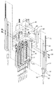
- FIG. 3 is a perspective view showing a state in which the driven shaft of the linear motion mechanism for two axes, the dispensing head, and the connecting portion thereof are separated from the 8-axis dispensing device shown in FIG.
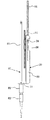
- FIG. 3 is a partial cross-sectional side view showing an internal structure of one linear motion mechanism, a dispensing head, and a plate accommodating the linear motion mechanism in the side view of FIG. From the 8-axis dispensing device shown in FIG. 1, a side surface showing a combination of a driven shaft, a dispensing head, a movable part including a connecting part thereof, and a guide mechanism in a linear motion mechanism for one axis. It is a figure.
- FIG. 9 is an enlarged cross-sectional view showing the internal structure of the stepping motor shown in FIG. 9 together with the lead shaft. It is a block diagram which shows the schematic structure of the position control system of a linear motion mechanism. It is a perspective view of the 4-axis dispensing apparatus which is the smallest unit of the 8-axis dispensing apparatus which concerns on this invention.
- an 8-axis dispensing device will be described as a preferred embodiment of the multi-axis actuator according to the present invention with reference to FIGS. 1 to 12.
- the conventional multi-axis type dispensing device When the conventional multi-axis type dispensing device is combined with a microplate for 96 (8 samples x 12 rows) sample, for example, as a clinical testing device, 8 sets of dispensing devices are assembled so as to be lined up in a row. It is configured as an 8-axis simultaneous control type, that is, a multi-axis simultaneous control type dispensing device. Then, the 8-axis dispensing device is configured to be collectively reciprocated between the suction place and the discharge place (that is, the microplate) of the liquid (for example, the reagent) by the transport mechanism.
- an 8-axis dispenser having both simultaneous control and independent control functions, which is inexpensive and effective in reducing the installation space, will be described as an embodiment of the multi-axis actuator. Since simultaneous control can be realized by collectively executing the same control operation on each axis that can be independently controlled, the independent control type dispensing device has both simultaneous control and independent control functions. It can be said that it is.
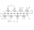
- FIG. 1 is a perspective view of an 8-axis dispensing device to which the present invention is applied
- FIGS. 2, 3, and 4 are a front view and a side view of the 8-axis dispensing device shown in FIG. 1, respectively.
- It is a rear view. 5 and 6 are a top view and a bottom view of the 8-axis dispensing device shown in FIG. 1, respectively.
- 7 is a cross-sectional view taken along the line AA of FIG. 2
- FIG. 8 shows the driven shaft and the dispensing head of the linear motion mechanism for two axes from the 8-axis dispensing device shown in FIG. It is a perspective view which shows the state which these connecting parts are separated. Further, FIG.
- FIG. 9 is a partial cross-sectional side view showing the linear motion mechanism for one axis and the internal structure of the dispensing head and the plate accommodating a part of the dispensing head in the side view of FIG.
- FIG. 10 shows a combination of a driven shaft, a dispensing head, a movable portion including a connecting portion thereof, and a guide mechanism in the linear motion mechanism for one axis from the 8-axis dispensing device shown in FIG. It is a side view extracted and shown.
- linear motion mechanism unit 100 in which two sets of linear motion mechanism units (hereinafter, may be referred to as a minimum linear motion mechanism unit) arranged in parallel to each other are arranged so as to be arranged in parallel with each other.
- the linear motion mechanism unit 100 includes a drive unit fixing member 40 including an upper installation plate 41 and a lower installation plate 42 having a two-stage shelf structure formed so as to have a distance equal to or higher than the height of the drive unit 10.
- the material of the drive unit fixing member 40 is preferably made of metal, but is not limited thereto.
- adjacent drive units 10 are alternately installed on the upper installation plate 41 and the lower installation plate 42.
- the adjacent drive units 10 are installed so that the upper installation plate 41 and the lower installation plate 42 have overlapping portions in the installation area of the adjacent drive units 10 in a plan view.
- the reason for doing this is to make the installation space of the four drive units 10 as small as possible in a plan view, but it suffices if the installation areas of the adjacent drive units 10 are adjacent to each other in a plan view, and the overlapping portions. May not be present.
- the drive unit fixing member 40 has a U-shaped (or U-shaped) cross section in which the upper installation plate 41 and the lower installation plate 42 are connected by a connecting plate 43 at one end side thereof.
- the connecting plate 43 is integrally formed with the lower installation plate 42, but may be integrally formed with the upper installation plate 41, or is separate from the upper installation plate 41 and the lower installation plate 42. May be.
- the hole 40a is a hole for screwing a screw or the like from the upper installation plate 41 toward the connecting plate 43 to connect them.
- Through holes (first through holes) 41a and 42a are formed in the upper installation plate 41 and the lower installation plate 42 at locations corresponding to the centers of the respective drive units 10, respectively, and the corresponding drive units are formed. It is designed to pass the driven shaft 20 of 10.
- the minimum linear motion mechanism unit on the right side of FIG. 3 will be referred to as the first set
- the minimum linear motion mechanism unit on the left side of FIG. 3 will be referred to as the second set. Since these two sets of the minimum linear motion mechanism units have almost the same configuration except for the arrangement relationship of the four linear motion mechanisms, the first set of the minimum linear motion mechanism units will be described below.
- the plate 50 is attached to the lower installation plate 42 as follows, but it is only an example, and it goes without saying that other attachment structures may be used.
- the plate 50 has flange-shaped protrusions 50-1 on both sides of its upper end.
- the plate 50 is fixed to the lower installation plate 42 by screwing the screw 50-2 into the screw hole of the lower installation plate 42 from the lower surface side of the protrusion 50-1 through the screw hole (or through hole).
- the movable portion of the dispensing device includes a driven shaft 20 and a dispensing head 60 extending in parallel with the driven shaft 20.
- the driven shaft 20 has a lead screw 21 having a male screw formed on the outer periphery thereof, and an extension shaft 22 connected to the lower end side of the lead screw 21 and extending in the axial direction of the lead screw 21.
- the driven shaft 20 also has a substantially L-shaped connecting portion 23 connecting the extension shaft 22 and the dispensing head 60 at the lower end portion of the extension shaft 22. It is desirable that the extension shaft 22 and the connecting portion 23 are integrated, but they may be separate bodies, and may be made of metal or resin.
- the lead screw 21 moves up and down in the axial direction by the rotary motor constituting the drive unit 10.
- the dispensing head 60 includes a nozzle 61, a tip 62 detachably attached to the lower end of the nozzle 61, and a pipe 63 connected to the upper end of the nozzle 61 so as to extend upward.
- the dispensing head 60 is usually made of a metal material such as stainless steel, but is not limited thereto.
- the driven shaft 20 extending downward from the drive unit 10 through the through hole 42a is along one of the two main surfaces of the plate 50 (hereinafter, may be referred to as a first main surface) with respect to the lower end portion of the plate 50. It extends slightly downward, and the connecting portion 23 enters the lower side of the lower end of the plate 50.
- the connecting portion 23 has an insertion hole 23a, and a cylindrical connector 24 is fixed to the insertion hole 23a so as to extend downward from the insertion hole 23a.
- the lower end side of the pipe 63 is inserted into the upper side of the connector 24 so as to extend upward from here, and is fixed by the screw 25.
- a communication hole 50a (FIGS. 7 and 9) extending from the lower end to the upper end is formed at a position corresponding to the insertion hole 23a in the plate 50.
- a hole 42b is formed at a position corresponding to the communication hole 50a.
- the pipe 63 fixed to the connecting portion 23 is led out to the space between the lower installation plate 42 and the upper installation plate 41 through the communication hole 50a and the hole 42b.
- a flexible tube (not shown) for sucking and discharging a liquid by air, for example, is connected to the upper end of the pipe 63 through the tip 62.
- the nozzle 61 is attached to the connector 24 protruding downward from the lower surface of the connecting portion 23.
- the nozzle 61 may be fixed to the connector 24, but a male screw may be formed on the outer periphery of the connector 24 and a female screw may be formed on the inner circumference of the nozzle 61 so as to be detachable.
- the connecting unit 23 and the dispensing head 60 connected to the connecting unit 23 also move up and down integrally. That is, the driven shaft 20 including the lead screw 21, the extension shaft 22, and the connecting portion 23, and the dispensing head 60 including the nozzle 61, the tip 62, and the pipe 63 act as a movable portion.
- the above structure is provided in the remaining linear motion mechanism 30 in the first set of minimum linear motion mechanism units, except whether it is installed in the lower installation plate 42 or the upper installation plate 41. Is almost the same. That is, in the linear motion mechanism (hereinafter, may be referred to as a lower linear motion mechanism) 30 installed on the lower installation plate 42, the driven shaft 20 extending downward from the drive unit 10 is the lower installation plate 42.
- the driven shaft 20 (lead screw 21) extending downward through the through hole 42a of the above and extending upward from the driving unit 10 extends upward through the through hole 41a of the upper installation plate 41.
- the driven shaft 20 extending downward from the drive unit 10 is downward through the through holes 41a and 42a. Extend. Then, in order to align the height positions of the two connecting portions 23 of the lower linear motion mechanism 30 and the height positions of the two connecting portions 23 of the upper linear motion mechanism 30 when the operation is off, the upper linear motion mechanism 30 is used.
- the length of the extension shaft 22 is made larger than the length of the extension shaft 22 of the lower linear motion mechanism 30 by the distance between the upper installation plate 41 and the lower installation plate 42.
- the above structure is the same for the four linear motion mechanisms 30 in the second set of minimum linear motion mechanism units.
- the pitch in the plan view of the adjacent linear motion mechanisms 30 in each of the first set and the second set of minimum linear motion mechanism units is P
- the first set when the pitch in the plan view of the adjacent linear motion mechanisms 30 in each of the first set and the second set of minimum linear motion mechanism units is P, the first set.
- the arrangement of the four linear motion mechanisms 30 in the minimum linear motion mechanism unit in the plan view and the arrangement of the four linear motion mechanisms 30 in the second set of the minimum linear motion mechanism units in the plan view are shifted by P / 2 pitch. It is arranged like this.
- the first set of four linear motion mechanisms 30 (drive unit 10) and the second set of four linear motion mechanisms 30 (drive unit 10) are arranged in a staggered (or zigzag) manner in a plan view.
- the four dispensing heads 60 driven by the linear motion mechanism 30 are alternately arranged in a row at predetermined intervals (P / 2 pitch).
- the pitch P / 2 is a preferable example, and any value smaller than P may be used.
- the first guide mechanism in the first set of minimum linear motion mechanism units will be described with reference to FIGS. 7, 9, and 10.
- the upper main surface of the plate 50 that is, the first main surface, has four pieces along the extension shaft 22 of the four linear motion mechanisms 30 in the first set of minimum linear motion mechanism units.
- Linear rail (first linear rail) 51 is provided.
- the linear rail 51 is formed on the plate 50 at intervals in the vertical direction from the main surface opposite to the first main surface (hereinafter, may be referred to as a second main surface) for screw insertion.
- the screw 52 is screwed into the linear rail 51 through the through hole 52a (FIG. 9) to be fixed to the first main surface of the plate 50.
- a linear guide that can slide along the linear rail 51 to a position near the upper part of the extension shaft 22 of the driven shaft 20, specifically, a position facing the linear rail 51 even if the extension shaft 22 moves up and down.
- the (first linear guide) 24 is fixed by the screw 26.
- the structure of the guide mechanism as described above is the same for the four linear motion mechanisms 30 in the second set of minimum linear motion mechanism units.
- the arrangement of the four linear rails 51 in the first set of minimum linear motion mechanism units (in FIG. 7).
- Upper side) and the arrangement of the four linear rails (second linear rails) 51 in the second set of minimum linear motion mechanism units are arranged so as to be offset by P / 2 pitch. It has become.
- the linear motion mechanism 30 in the present embodiment includes a drive unit 10 by a rotary motor and a lead screw 21 that converts the rotation of the rotary motor into linear motion.
- a two-phase hybrid stepping motor is used as the rotary motor.
- the two-phase hybrid type stepping motor 70 adopted in the present embodiment has a general hybrid type stepping motor in which the stator portion is configured except that the rotor portion is of the feed screw type. It is the same as the composition of.
- the stator portion includes a cylindrical stator 71 made by laminating electromagnetic steel sheets, and a coil 72 wound and arranged adjacent to the stator 71.
- the rotor portion is hollow, and a hollow rotor 73 rotatably arranged with a minute gap on the inner peripheral side of the stator 71 and a cylindrical lead fixed to the inner peripheral side of the rotor 73.
- the lead nut 74 extends from one end side to the outside of the other end side of the stepping motor 70 main body, and a female screw is formed on the inner diameter side thereof.
- the lead nuts 74 are also supported by ball bearings 75 on the inside near both ends of the stepping motor 70, respectively. Since the female screw of the lead nut 74 is screwed with the male screw of the lead screw 21 which is sufficiently longer than the main body of the stepping motor 70, the lead screw 21 operates linearly by the rotation of the rotor portion.
- the encoder 80 employs an optical incremental method, and includes the disk 81 and a substrate 82 fixedly arranged so as to face the disk 81 on the outside of the other end side of the stepping motor 70 main body.
- the encoder 80 in the present embodiment is a reflection type, and as is well known, a plurality of grid-like reflection portions are provided on the surface of the disk 81 facing the substrate 82.
- a light emitting portion and a light receiving portion are provided on the surface of the substrate 82 facing the disk 81, and the light emitted from the light emitting portion is reflected by the reflecting portion of the disk 81 and incident on the light receiving portion.
- the reflected light incident on the light receiving unit is converted into an electric signal and output.
- the encoder 80 is configured to output two continuous voltage signals (digital signals by a square wave) whose phase is 90 degrees out of phase with the reflected light signal incident on the light receiving portion.
- the rotational displacement amount, rotational speed, and rotational direction of the lead nut 74 calculated based on these two voltage signals are converted into the lead screw 21, that is, the linear displacement amount (position) of the movable part, the linear motion speed, and the linear motion direction. Therefore, it is used for position control and abnormality detection of the dispensing head 60.
- the lead screw 21 moves linearly by 1 mm for each rotation of the lead nut 74. Since this type of encoder is well known, detailed description thereof will be omitted.
- the encoder 80 configured as described above is covered with an encoder case 83 attached to the other end side of the stepping motor 70 main body.
- a shaft body 21-1 having a smaller diameter is provided at the lower end of the lead shaft 21, and a through hole 21a penetrating the shaft body 21-1 is formed in the shaft body 21-1.
- the through hole 21a is a hole through which a pin for connecting the lead shaft 21 and the extension shaft 22 is passed.
- a connector 11 for connecting the encoder 80 and the stepping motor 70 to the outside is provided on the upper part of the drive unit 10.
- the connection direction is changed for each drive unit 10 so that the connection can be facilitated.
- a general lead screw method has a configuration of a motor + a coupling + a male screw and a female screw screwed with the male screw. Since it does not have a coupling, it is an inexpensive and space-saving linear motion mechanism.
- the drive unit 10 of the lower linear motion mechanism 30 having only the lead shaft 21 of the driven shaft 20 is installed on the lower installation plate 42.
- the lower side of the lead shaft 21 is made to protrude from the through hole 42a.
- a vertical hole for receiving the shaft body 21-1 provided at the lower end of the lead shaft 21 and a pin 27 are inserted into the through hole 21a of the shaft body 21-1 received in the vertical hole.
- a horizontal hole 22a for the purpose is formed.
- the first linear guide 24 is mounted on the first linear rail 51 corresponding to the extension shaft 22 of the corresponding lower linear motion mechanism 30 in advance.
- the nozzle 61 and the tip 62 are mounted on the lower side of the connecting portion 23, while the pipe 63 of the dispensing head 60 is mounted on the upper side of the connecting portion 23, and the pipe 63 is the plate 50. It is performed in a state of being inserted into the communication hole 50a of.
- the nozzle 61 may be attached to the connecting portion 23 after the above-mentioned connection as long as it has a removable structure.
- the first linear guide 24 is positioned at a position where it can be screwed to the extension shaft 22 with a screw 26, and the first linear guide 24 is fixed to the extension shaft 22.
- the lower side of the lead shaft 21 projects from the through hole 41a of the upper installation plate 41 in a state where the upper installation plate 41 of the drive unit fixing member 40 is attached.
- the lead shaft 21 and the extension shaft 22 of the upper linear motion mechanism 30 are installed by the same method as described above by using the space between the upper installation plate 41 and the lower installation plate 42. Perform connection work.
- the handling of the first linear rail 51, the first linear guide 24, and the dispensing head 60 side is the same as described above.
- the assembly of the second set of minimum linear motion mechanism units is also performed by the same method in parallel with the assembly of the first set of minimum linear motion mechanism units.
- FIG. 12 is a block diagram of a control system that individually controls the stepping motor 70.
- the control system controls the stepping motor 70 based on the output signal (position detection signal) of the encoder 80 and the parameters and drive sequences preset by the host device 95, thereby moving the stepping motor 70 up and down.
- It has a motor control device 92 that individually executes position control in a direction.
- the motor control device 92 includes a control circuit that generates a position control signal based on parameters and a drive sequence preset by the host device 95, and a motor that drives the stepping motor 70 based on the generated signal. Includes drive circuit.
- the encoder 80 detects the rotational position of the stepping motor 70 and outputs it as a digital signal by a square wave.
- This digital signal is two consecutive rectangular wave signals (A-phase signal and B-phase signal) whose phase shifts by 90 degrees with respect to the rotation direction of the stepping motor 70.
- the rotation direction is determined by identifying the phase that has changed earlier in the A-phase signal and the B-phase signal.
- the two digital signals output from the encoder 80 are input to the motor control device 92.
- the motor control device 92 determines the rotation direction based on the changes in the A-phase signal and the B-phase signal.
- the motor control device 92 also outputs an operation command converted into a vertical movement amount and a movement speed of the dispensing head 60 to the stepping motor 70 based on preset parameters, a drive sequence, and the like from the host device 95.
- the motor control device 92 further compares the value detected at the current position of the dispensing head 60 with the designated position based on the drive sequence set by the host device 95 by two digital signals from the encoder 80, and the deviation thereof. Is output to the stepping motor 70 to correct the above.
- the motor control device 92 shows the behavior contrary to the command from the motor control device 92. It is possible to detect this and stop the control that has been executed until now, or remove the abnormality and restart the control. Since the above control modes are well known, detailed description thereof will be omitted.
- an optical path blocking signal is sent from the photo sensor to the motor control device 92. It may be output to.
- the optical path cutoff signal can be used for determining a reference point for positioning control of the dispensing head 60, so-called origin positioning. It can also be used as an upper limit sensor for each driven shaft 20 (lead screw 21). Since this type of control mode is also well known, detailed description thereof will be omitted.
- the control system as described above is individually provided for each of the eight axes, and when performing independent control, a different command signal is given to the motor control device 92 of each control system from the host device 95 for each control system. Then, a different dispensing operation is executed for each dispensing device. On the other hand, when the simultaneous control is executed, the same command signal is given from the host device 95 to the motor control device 92 of each control system, and all the dispensing devices execute the same dispensing operation.
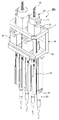
- a 4-axis dispensing device will be described as an embodiment of the minimum linear motion mechanism unit, which is the smallest unit of the dispensing device in the present invention, with reference to FIG.
- This 4-axis dispensing device can be considered to be the same as the left side of the 8-axis dispensing device described in FIG. 1, that is, the second set of minimum linear motion mechanism units. Therefore, in FIG. 13, the same components as those in FIG. 1 are given the same reference numbers, and the description will be simplified.
- linear motion mechanisms 30 having a drive unit 10 driven by a rotary motor and a driven shaft 20 driven by the drive unit 10 are arranged in a row in a plan view. It has a linear motion mechanism unit 200 arranged in a shape.
- the linear motion mechanism unit 200 includes a drive unit fixing member 40 including an upper installation plate 41 and a lower installation plate 42 having a two-stage shelf structure formed so as to have a distance equal to or higher than the height of the drive unit 10.
- adjacent drive units 10 are alternately installed on the upper installation plate 41 and the lower installation plate 42. Further, also in the present embodiment, the adjacent drive units 10 are installed so as to form a portion of the upper installation plate 41 and the lower installation plate 42 that overlap each other in the installation area of the adjacent drive units 10 in a plan view. As a result, as described above, the installation space of the four drive units 10 in a plan view is made as small as possible.
- the drive unit fixing member 40 has a U-shaped (or U-shaped) cross section in which the upper installation plate 41 and the lower installation plate 42 are connected by a connecting plate 43 at one end side thereof. Again, the connecting plate 43 is integrally formed with the lower installation plate 42. As described with reference to FIG. 9, through holes (first through holes) 41a and 42a are formed in the upper installation plate 41 and the lower installation plate 42 at locations corresponding to the centers of the drive units 10, respectively. It is designed to pass the driven shaft 20 of the driving unit 10 to be driven.
- the internal structure of the drive unit 10 constituting the linear motion mechanism 30, the configuration of the driven shaft 20, that is, the configuration of the extension shaft 22, the connecting portion 23, and the dispensing head 60 are those in the above-mentioned 8-axis dispensing device. Since it is exactly the same as, the explanation is omitted.
- a multi-axis type dispensing device For a multi-axis type dispensing device, it is required to reduce the pitch (interval) between the dispensing heads. This is because by reducing the pitch between the dispensing heads, the entire multi-axis dispensing device can be made compact and the movable range can be increased.
- the diameter of the drive unit in order to reduce the pitch between the dispensing heads, the diameter of the drive unit must be reduced, which is why. Must make the rotary motor smaller. This means that the thrust (driving torque) of each axis becomes small.
- a predetermined thrust is required for the vertical movement of the dispensing head. This is done, for example, with reference to FIG.
- the pitch between the dispensing heads is reduced, and the diameter of the drive unit 10 (particularly the stepping motor 70) is not reduced. Since a predetermined thrust (driving torque) can be obtained when the dispensing head moves up and down, the above-mentioned problems do not occur.
- an 8-axis dispensing device can be provided at low cost.
- the present invention is not limited to the above embodiment. That is, the present invention can be applied to both an independent control type and a simultaneous control type as long as it is a multi-axis dispenser having four or more axes, and further, it is not limited to the dispenser and is a general multi-axis actuator. Applicable to.
Landscapes
- Analytical Chemistry (AREA)
- Immunology (AREA)
- Physics & Mathematics (AREA)
- Health & Medical Sciences (AREA)
- Life Sciences & Earth Sciences (AREA)
- Chemical & Material Sciences (AREA)
- General Health & Medical Sciences (AREA)
- Biochemistry (AREA)
- Power Engineering (AREA)
- General Physics & Mathematics (AREA)
- Engineering & Computer Science (AREA)
- Pathology (AREA)
- Connection Of Motors, Electrical Generators, Mechanical Devices, And The Like (AREA)
- Automatic Analysis And Handling Materials Therefor (AREA)
Applications Claiming Priority (2)
| Application Number | Priority Date | Filing Date | Title |
|---|---|---|---|
| JP2020-112622 | 2020-06-30 | ||
| JP2020112622A JP7416418B2 (ja) | 2020-06-30 | 2020-06-30 | 多軸アクチュエータ |
Publications (1)
| Publication Number | Publication Date |
|---|---|
| WO2022004045A1 true WO2022004045A1 (ja) | 2022-01-06 |
Family
ID=79315245
Family Applications (1)
| Application Number | Title | Priority Date | Filing Date |
|---|---|---|---|
| PCT/JP2021/006041 Ceased WO2022004045A1 (ja) | 2020-06-30 | 2021-02-18 | 多軸アクチュエータ |
Country Status (2)
| Country | Link |
|---|---|
| JP (1) | JP7416418B2 (https=) |
| WO (1) | WO2022004045A1 (https=) |
Citations (6)
| Publication number | Priority date | Publication date | Assignee | Title |
|---|---|---|---|---|
| JP2010107352A (ja) * | 2008-10-30 | 2010-05-13 | Nippon Pulse Motor Co Ltd | シリンダユニット |
| JP2010107353A (ja) * | 2008-10-30 | 2010-05-13 | Nippon Pulse Motor Co Ltd | 分注装置 |
| JP2014029333A (ja) * | 2012-07-26 | 2014-02-13 | Ttp Labtech Ltd | 液体分注装置 |
| JP2014508034A (ja) * | 2011-01-28 | 2014-04-03 | インテグラ バイオサイエンシズ コープ. | マルチチャンネルウェルプレート充填システム |
| WO2018193719A1 (ja) * | 2017-04-20 | 2018-10-25 | ヤマハ発動機株式会社 | 細胞移動装置及び細胞移動方法 |
| JP2019523122A (ja) * | 2016-06-29 | 2019-08-22 | エッペンドルフ アクチエンゲゼルシャフトEppendo | 計量ヘッド、計量ヘッドを備えた計量装置、および計量ヘッドを用いた計量方法 |
-
2020
- 2020-06-30 JP JP2020112622A patent/JP7416418B2/ja active Active
-
2021
- 2021-02-18 WO PCT/JP2021/006041 patent/WO2022004045A1/ja not_active Ceased
Patent Citations (6)
| Publication number | Priority date | Publication date | Assignee | Title |
|---|---|---|---|---|
| JP2010107352A (ja) * | 2008-10-30 | 2010-05-13 | Nippon Pulse Motor Co Ltd | シリンダユニット |
| JP2010107353A (ja) * | 2008-10-30 | 2010-05-13 | Nippon Pulse Motor Co Ltd | 分注装置 |
| JP2014508034A (ja) * | 2011-01-28 | 2014-04-03 | インテグラ バイオサイエンシズ コープ. | マルチチャンネルウェルプレート充填システム |
| JP2014029333A (ja) * | 2012-07-26 | 2014-02-13 | Ttp Labtech Ltd | 液体分注装置 |
| JP2019523122A (ja) * | 2016-06-29 | 2019-08-22 | エッペンドルフ アクチエンゲゼルシャフトEppendo | 計量ヘッド、計量ヘッドを備えた計量装置、および計量ヘッドを用いた計量方法 |
| WO2018193719A1 (ja) * | 2017-04-20 | 2018-10-25 | ヤマハ発動機株式会社 | 細胞移動装置及び細胞移動方法 |
Also Published As
| Publication number | Publication date |
|---|---|
| JP2022011464A (ja) | 2022-01-17 |
| JP7416418B2 (ja) | 2024-01-17 |
Similar Documents
| Publication | Publication Date | Title |
|---|---|---|
| KR0156592B1 (ko) | 액추에이터 및 액추에이터 시스템 | |
| KR101275978B1 (ko) | Xy 테이블 액츄에이터 | |
| US9095984B2 (en) | Force control robot | |
| AU2002320177A1 (en) | Precision fluid dispensing system | |
| US20090001852A1 (en) | Piezoelectric actuator, piezoelectric actuator device, lens barrel, optical device and manufacturing method thereof | |
| WO2022004045A1 (ja) | 多軸アクチュエータ | |
| JP7437027B2 (ja) | 多軸リニアモータアクチュエータ | |
| CN115668708A (zh) | 具有改进的旋转角精度的马达控制装置 | |
| EP3947979A1 (en) | Acoustic principle based fluid pump | |
| CN116481804A (zh) | 测试装置 | |
| JP7437686B2 (ja) | 多軸リニアモータアクチュエータにおけるコイルユニット及びその製造方法 | |
| JP2024045576A (ja) | 多軸リニアモータアクチュエータ | |
| CN109863331B (zh) | 驱动器 | |
| JP7707783B2 (ja) | ロボット関節機構、ロボットおよびロボット関節機構の組立方法 | |
| CN110501328B (zh) | 用于单道扫描icp光谱仪的光栅驱动模块及控制方法 | |
| CN212137459U (zh) | 一种电缸 | |
| CN112145653B (zh) | 一种多级齿轮传动结构 | |
| KR102057236B1 (ko) | 탐지 모듈에 기초하는 액추에이터 일체형 로봇 구동 컨트롤러 | |
| US6823756B2 (en) | Displacement unit | |
| CN117979678A (zh) | 贴片机及其机头 | |
| CN223447225U (zh) | 注射泵 | |
| CN224102286U (zh) | 锁螺丝装置 | |
| CN219139278U (zh) | 一种柱塞泵 | |
| JP7804445B2 (ja) | グリッパ | |
| CN215030609U (zh) | 一种多功能制造的标准平台 |
Legal Events
| Date | Code | Title | Description |
|---|---|---|---|
| 121 | Ep: the epo has been informed by wipo that ep was designated in this application |
Ref document number: 21834357 Country of ref document: EP Kind code of ref document: A1 |
|
| NENP | Non-entry into the national phase |
Ref country code: DE |
|
| 122 | Ep: pct application non-entry in european phase |
Ref document number: 21834357 Country of ref document: EP Kind code of ref document: A1 |