WO2021260782A1 - 心拍数検知方法、装置およびプログラム - Google Patents
心拍数検知方法、装置およびプログラム Download PDFInfo
- Publication number
- WO2021260782A1 WO2021260782A1 PCT/JP2020/024526 JP2020024526W WO2021260782A1 WO 2021260782 A1 WO2021260782 A1 WO 2021260782A1 JP 2020024526 W JP2020024526 W JP 2020024526W WO 2021260782 A1 WO2021260782 A1 WO 2021260782A1
- Authority
- WO
- WIPO (PCT)
- Prior art keywords
- heart rate
- value
- ecg waveform
- rate detection
- measurement
- Prior art date
- Legal status (The legal status is an assumption and is not a legal conclusion. Google has not performed a legal analysis and makes no representation as to the accuracy of the status listed.)
- Ceased
Links
Images


Classifications
-
- A—HUMAN NECESSITIES
- A61—MEDICAL OR VETERINARY SCIENCE; HYGIENE
- A61B—DIAGNOSIS; SURGERY; IDENTIFICATION
- A61B5/00—Measuring for diagnostic purposes; Identification of persons
- A61B5/02—Detecting, measuring or recording for evaluating the cardiovascular system, e.g. pulse, heart rate, blood pressure or blood flow
- A61B5/024—Measuring pulse rate or heart rate
- A61B5/0245—Measuring pulse rate or heart rate by using sensing means generating electric signals, i.e. ECG signals
-
- A—HUMAN NECESSITIES
- A61—MEDICAL OR VETERINARY SCIENCE; HYGIENE
- A61B—DIAGNOSIS; SURGERY; IDENTIFICATION
- A61B5/00—Measuring for diagnostic purposes; Identification of persons
- A61B5/24—Detecting, measuring or recording bioelectric or biomagnetic signals of the body or parts thereof
- A61B5/316—Modalities, i.e. specific diagnostic methods
- A61B5/318—Heart-related electrical modalities, e.g. electrocardiography [ECG]
- A61B5/339—Displays specially adapted therefor
-
- A—HUMAN NECESSITIES
- A61—MEDICAL OR VETERINARY SCIENCE; HYGIENE
- A61B—DIAGNOSIS; SURGERY; IDENTIFICATION
- A61B5/00—Measuring for diagnostic purposes; Identification of persons
- A61B5/24—Detecting, measuring or recording bioelectric or biomagnetic signals of the body or parts thereof
- A61B5/316—Modalities, i.e. specific diagnostic methods
- A61B5/318—Heart-related electrical modalities, e.g. electrocardiography [ECG]
- A61B5/346—Analysis of electrocardiograms
-
- A—HUMAN NECESSITIES
- A61—MEDICAL OR VETERINARY SCIENCE; HYGIENE
- A61B—DIAGNOSIS; SURGERY; IDENTIFICATION
- A61B5/00—Measuring for diagnostic purposes; Identification of persons
- A61B5/72—Signal processing specially adapted for physiological signals or for diagnostic purposes
- A61B5/7221—Determining signal validity, reliability or quality
-
- A—HUMAN NECESSITIES
- A61—MEDICAL OR VETERINARY SCIENCE; HYGIENE
- A61B—DIAGNOSIS; SURGERY; IDENTIFICATION
- A61B5/00—Measuring for diagnostic purposes; Identification of persons
- A61B5/72—Signal processing specially adapted for physiological signals or for diagnostic purposes
- A61B5/7235—Details of waveform analysis
- A61B5/7242—Details of waveform analysis using integration
-
- A—HUMAN NECESSITIES
- A61—MEDICAL OR VETERINARY SCIENCE; HYGIENE
- A61B—DIAGNOSIS; SURGERY; IDENTIFICATION
- A61B5/00—Measuring for diagnostic purposes; Identification of persons
- A61B5/72—Signal processing specially adapted for physiological signals or for diagnostic purposes
- A61B5/7235—Details of waveform analysis
- A61B5/7246—Details of waveform analysis using correlation, e.g. template matching or determination of similarity
-
- A—HUMAN NECESSITIES
- A61—MEDICAL OR VETERINARY SCIENCE; HYGIENE
- A61B—DIAGNOSIS; SURGERY; IDENTIFICATION
- A61B5/00—Measuring for diagnostic purposes; Identification of persons
- A61B5/40—Detecting, measuring or recording for evaluating the nervous system
- A61B5/4029—Detecting, measuring or recording for evaluating the nervous system for evaluating the peripheral nervous systems
- A61B5/4035—Evaluating the autonomic nervous system
Definitions
- the present invention relates to a heart rate detection method, device and program that presents an accurate heart rate.
- Heart rate or its fluctuation is biometric information obtained from ECG (Electrocardiography), and is used for evaluation of autonomic nervous function and index of exercise intensity in daily life and resting state.
- measuring the heart rate over a relatively long time such as daily life using a wearable ECG waveform acquisition / heart rate measurement device is useful for managing the physical condition of the user.
- Patent Document 1 discloses a method capable of appropriately detecting a heartbeat when noise is superimposed on an ECG waveform, such as measurement by a wearable device.
- the heartbeat detection may be erroneous. For example, when an R wave to be detected is missed, a wave that is not an R wave may be detected as an R wave.
- the wearable heart rate measuring device in order to avoid such an error in heart rate detection, the heart rate is moved and averaged over a certain period of time, or an IIR (Infinite impulse response) filter is used to prevent an error in heart rate detection.
- IIR Infinite impulse response
- a method of calculating and presenting an average heart rate (hereinafter referred to as "HR” (Heart rate)) that suppresses fluctuations in the resulting instantaneous heart rate (hereinafter referred to as "IHR” (Instantaneous Heart rate)) is adopted.
- HR Heart rate
- IHR Instantaneous Heart rate
- FIG. 10 is a part of the ECG waveform measured using a wearable device.
- FIG. 10 also shows the RR interval [ms] corresponding to the heart rate at the timing when the R wave is detected (black diamond in the figure).
- the method disclosed in Patent Document 1 can be used for the detection of the RR interval.
- FIG. 11 shows the instantaneous heart rate IHR and the average heart rate HR calculated based on the instantaneous heart rate IHR.
- a black diamond indicates an instantaneous heart rate
- a white circle indicates an average heart rate.
- the average heart rate HR [n] is calculated by the following formula with respect to the time series data IHR [n] of the instantaneous heart rate.
- FIG. 12 shows the measurement results of the 3-axis acceleration simultaneously measured by the accelerometer built in the wearable device used for the above-mentioned ECG waveform measurement.
- the solid line 51 shows the acceleration on the x-axis
- the broken line 52 shows the acceleration on the y-axis
- the dotted line 53 shows the acceleration on the z-axis.
- the average heart rate shows a stable measurement.
- the user may recognize the average heart rate as an accurate value even though it is not an accurate value.
- an abnormal value may be presented to the user as an accurate value even though the heart rate detection contains an error and is not measured as an accurate value. .. Therefore, in order to present an accurate heart rate, an index that replaces the average heart rate is needed.
- the heart rate detection method includes a step of measuring an ECG waveform, a step of calculating a heart rate from the ECG waveform, and a step of calculating the ECG waveform between sampling times.
- the heart rate detection device calculates the heart rate from the measurement unit that measures the ECG waveform and the ECG waveform, calculates the difference value of the potential of the ECG waveform between the sampling times, and the difference. Whether to display the heart rate at the measurement time by comparing the integrated value with the reference value and the calculation unit that integrates the value between the measurement time and an arbitrary time before the measurement to calculate the integrated value. It is provided with a determination unit for determining whether or not.
- the heart rate detection program includes a step of measuring the ECG waveform, a step of calculating the heart rate from the ECG waveform, and a step of calculating the difference value of the potential of the ECG waveform between the sampling times. , The step of integrating the difference value between the measurement time and an arbitrary time before the measurement to calculate the integrated value, and comparing the integrated value with the reference value to display the heart rate at the measured time.
- a heart rate detecting device is made to function, which comprises executing a process including a step of determining whether or not to do so.
- the present invention it is possible to provide a heart rate detection method, a device and a program for presenting an accurate heart rate.
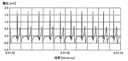
- FIG. 1 is a diagram showing an ECG waveform for explaining a heart rate detection method according to the first embodiment of the present invention.
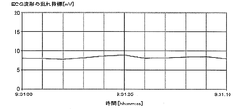
- FIG. 2 is a diagram showing changes over time of an index in the heart rate detection method according to the first embodiment of the present invention.
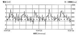
- FIG. 3 is a diagram showing an ECG waveform and an RR interval for explaining the heart rate detection method according to the first embodiment of the present invention.
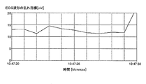
- FIG. 4 is a diagram showing changes over time of an index in the heart rate detection method according to the first embodiment of the present invention.
- FIG. 5 is a diagram showing changes over time of the index in the conventional method.
- FIG. 6 is a block diagram of the heart rate detecting device according to the first embodiment of the present invention.
- FIG. 7 is a flowchart showing a heart rate detection method according to the first embodiment of the present invention.
- FIG. 8 is a flowchart showing a heart rate detection method according to a second embodiment of the present invention.
- FIG. 9 is a diagram showing a configuration example of a computer according to an embodiment of the present invention.
- FIG. 10 is a diagram showing an ECG waveform and an RR interval for explaining a conventional heart rate detection method.
- FIG. 11 is a diagram showing an instantaneous heart rate and an average heart rate for explaining a conventional heart rate detection method.
- FIG. 12 is a diagram showing triaxial acceleration in a wearable device for explaining a conventional heart rate detection method.
- an index that replaces the average heart rate is necessary.
- a numerical value indicating the disturbance of the ECG waveform is used as a new index.
- the potential greatly fluctuates beyond the amplitude (about 3 mV) of the normal ECG waveform.
- the instantaneous heart rate extracted from this waveform has low reliability even if the variation is small. Therefore, in the present invention, the disturbance of the ECG waveform itself is quantified and used as an index.
- the amount of change in the potential of the ECG waveform (hereinafter referred to as "ECG potential”) for each sampling cycle (hereinafter referred to as "time difference value”) is integrated over a certain period of time. ..
- the amount of change (time difference value) for each sampling cycle is
- the sampling period (interval) in the measurement of this ECG waveform is 5 ms.
- the time difference value is integrated and the integrated value is used as an index.
- the total time was set to the past 1 second.
- FIG. 2 shows the time course of the integrated value, which is the above-mentioned index.
- the integrated value which is an index, is about 10 mV or less, which is almost constant.
- FIG. 3 shows an ECG waveform including fluctuation of the baseline as an example of the ECG waveform in which noise is suppressed.
- the sampling period (interval) is 5 ms.
- FIG. 3 also shows the RR interval [ms] at the timing when the R wave is detected.
- the R wave is stably observed at an almost constant value and is detected as an accurate value.
- the time difference value was integrated for this ECG waveform, and the integrated value was used as an index.
- the total time was set to the past 1 second.
- FIG. 4 shows the change over time of the integrated value, which is an index.
- the integrated value, which is an index is at least about 20 mV or less and is almost constant.
- the reference value for whether or not the R wave can be detected due to the disturbance of the ECG waveform is appropriate if it is set to 20 mV.
- the present invention is based on the finding that an accurate heart rate can be presented when the index obtained by integrating the amount of change (time difference value) of the ECG potential for each sampling cycle is 20 mV or less as a reference value.
- a method is disclosed in which the amount of change in the potential of the ECG waveform for each sampling cycle is used to determine whether or not the size of the wearable device is appropriate (Japanese Patent Laid-Open No. 2018-183412).
- 500 mV sampling interval is 5 ms
- 100 mV per second is used as a reference value in the determination with respect to the integrated value of the amount of change for 5 seconds.
- FIG. 5 shows an example of an index used for determining the size of a wearable device.
- the ECG waveform shown in FIG. 10 is plotted using the integrated value of the amount of change in potential over the past 1 second as an index. According to this index, it is 100 mV or less, which is a reference value in almost the measurement region, and it is determined that the size of the wearable device is accurate.
- this method differs from the heart rate detection method according to the embodiment of the present invention in the object to be inspected (determined), and therefore the reference value used for the inspection (judgment) is also significantly different.
- FIG. 6 shows a block diagram of an example of the configuration of the heart rate detection device 1 according to the present embodiment.
- the heart rate detection device 1 includes a measurement unit 11, a storage unit 12, a calculation unit 13, a determination unit 14, and an output unit 15.
- the measuring unit 11 measures the ECG waveform, and as an example, an electrocardiograph in a wearable device is used.
- the storage unit 12 stores the time measured by the electrocardiograph and the ECG potential.
- the calculation unit 13 acquires the time and ECG potential measured by the electrocardiograph from the storage unit 12, calculates the time difference value, and calculates the integrated value. In addition, a calculation is performed based on the ECG waveform in order to detect the heart rate (RR interval).
- the determination unit 14 compares the integrated value of the calculated time difference value of the ECG potential with the reference value, and determines whether or not the heart rate acquired at the integrated time is accurate (validity).
- the output unit 15 outputs the calculated heart rate. In addition, it is possible to output that the heart rate was not accurately measured, the measured ECG waveform, the time difference value, and the integrated value.
- FIG. 7 shows a flowchart for explaining the heart rate detection method according to the present embodiment.
- the measured time and the ECG waveform (ECG potential) are stored (step 22).
- the time difference value is calculated using the stored ECG waveform (ECG potential) (step 23).
- the time difference value is the ECG potential x [n] measured by the measuring unit 11 at an arbitrary time t [n] and the latest time t [n-1] before the measurement acquired from the storage unit 12.
- this time difference value is integrated between the measurement time t [n] and an arbitrary time t [nm] before the measurement (hereinafter, “integrated time”) to calculate the integrated value (step). 24).
- this integrated value is compared with the reference value, and the determination is made as follows (step 25).
- the integrated value is equal to or less than the reference value, it is determined that the heart rate calculated from the ECG waveform is accurate in the integrated time including the measurement time t [n].
- the heart rate at the measurement time t [n] is calculated from the ECG waveform (step 26).
- the heart rate (RR interval) can be calculated, for example, by comparing the ECG waveform with a predetermined threshold value based on the change in the time-difference value.
- the measurement accuracy can be improved by comparing a plurality of ECG waveforms with a predetermined threshold value by using the change of the value obtained by the time difference (see Patent Document 1).
- the integrated value exceeds the reference value, it is determined that the heart rate calculated from the ECG waveform is not accurate in the integrated time.
- the heart rate is not calculated, and it is output (presented) that the accurate heart rate is not measured (step 28).
- the most recent accurate heart rate before the measurement time t [n] may be presented, or a blank (state in which nothing is displayed) may be presented.
- the reference value is 20 mV.
- the index shown in FIG. 2 is calculated. Next, since the calculated index is 20 mV or less, it is determined that the heart rate calculated from the ECG waveform is accurate. Therefore, the heart rate calculated from the ECG waveform shown in FIG. 1 is output (presented).
- the index shown in FIG. 4 is calculated.
- the heart rate calculated from the ECG waveform shown in FIG. 3 is output (presented).
- the index shown in FIG. 5 is calculated.
- the calculated index is 20 mV or more, it is determined that the heart rate calculated from the ECG waveform is not accurate. Therefore, it is output (presented) that the accurate heart rate is not measured.
- the most recent accurate heart rate before the measurement time is presented.
- a blank (nothing is displayed) is presented.
- the present embodiment it is possible to avoid presenting an abnormal value to the user even though the heart rate is not measured as an accurate value, and it is accurate. Only heart rate numbers can be presented to the user.
- ⁇ Second embodiment> A heart rate detection device and a method according to a second embodiment of the present invention will be described with reference to FIG.
- the configuration of the heart rate detection device according to the second embodiment is the same as that of the first embodiment.
- the heart rate is calculated before the determination. do.
- FIG. 8 shows a flowchart for explaining the heart rate detection method according to the present embodiment.
- the measured time and the ECG waveform (ECG potential) are stored (step 32).
- the heart rate is calculated and stored from the ECG waveform (step 33).
- the heart rate (RR interval) can be calculated, for example, by comparing the ECG waveform with a predetermined threshold value based on the change in the time-difference value. Further, for example, the measurement accuracy can be improved by comparing a plurality of ECG waveforms with a predetermined threshold value by using the change of the value obtained by the time difference (see Patent Document 1).
- the time difference value is calculated using the stored ECG waveform (ECG potential) (step 34).
- the time difference value is the ECG potential x [n] measured by the measuring unit 11 at an arbitrary time t [n] and the latest time t [n-1] before the measurement acquired from the storage unit 12.
- this time difference value is integrated between the measurement time t [n] and an arbitrary time t [nm] before the measurement (hereinafter, “integrated time”) to calculate the integrated value (step). 35).
- this integrated value is compared with the reference value, and the determination is made as follows (step 36).
- the integrated value is less than or equal to the reference value, it is determined that the heart rate calculated from the ECG waveform is accurate in the integrated time.
- the heart rate calculated from the ECG waveform measured during the integrated time is acquired from the storage unit 12 and output (presented) (step 37).
- the integrated value exceeds the reference value, it is determined that the heart rate calculated from the ECG waveform is not accurate in the integrated time.
- the accurate heart rate is not measured (step 38).
- the most recent accurate heart rate may be displayed or nothing may be displayed.
- the heart rate detection method according to the present embodiment also has the same effect as the heart rate detection method according to the first embodiment, and is abnormal despite the situation where the heart rate is not measured as an accurate value. It is possible to avoid presenting an accurate numerical value to the user, and it is possible to present only an accurate heart rate numerical value to the user.
- the heart rate detection device may be worn on the user's body as an integrated wearable device.
- the heart rate detection device may be equipped with a storage unit, a calculation unit, and a determination unit in a smartphone, a server, or the like outside the wearable device by attaching the measurement unit to the user's body as a wearable device. ..
- the heart rate detection device is provided with a transmission / reception unit for each of the wearable device and an external server, etc., and the ECG waveform measured by the wearable device is transmitted to the server or the like, and is stored, calculated, determined, or the like by the server or the like.
- the heart rate and the like may be output to a server or the like, or may be transmitted to a wearable device or the like and output.
- ECG potential ECG potential
- the ECG waveform may be acquired from the storage unit to determine the validity of the heart rate.
- FIG. 9 shows a configuration example of the computer 40 in the heart rate detection device according to the embodiment of the present invention.
- the heart rate detection device can be realized by a computer 40 including a CPU (Central Processing Unit) 43, a storage device (storage unit) 42, and an interface device 41, and a program for controlling these hardware resources.
- the interface device 41 is connected to the measurement unit and the output unit of the heart rate detection device according to the embodiment of the present invention.
- the CPU 43 executes the process according to the embodiment of the present invention according to the heart rate detection program stored in the storage device 42. In this way, the heart rate detection program activates the heart rate detection device.
- a computer may be provided inside the device, or at least one part of the functions of the computer may be realized by using an external computer.
- the storage unit may also use a storage medium outside the device, or may read out and execute a heart rate detection program stored in the storage medium.
- the storage medium includes various magnetic recording media, optical magnetic recording media, CD-ROMs, CD-Rs, and various memories.
- the heart rate detection program may be supplied to the computer via a communication line such as the Internet.
- the present invention can be applied to a technique for analyzing a biological signal obtained from an ECG waveform.
Landscapes
- Health & Medical Sciences (AREA)
- Life Sciences & Earth Sciences (AREA)
- Engineering & Computer Science (AREA)
- Cardiology (AREA)
- Heart & Thoracic Surgery (AREA)
- Surgery (AREA)
- Veterinary Medicine (AREA)
- Biophysics (AREA)
- Pathology (AREA)
- Biomedical Technology (AREA)
- Public Health (AREA)
- Medical Informatics (AREA)
- Molecular Biology (AREA)
- Physics & Mathematics (AREA)
- Animal Behavior & Ethology (AREA)
- General Health & Medical Sciences (AREA)
- Signal Processing (AREA)
- Physiology (AREA)
- Artificial Intelligence (AREA)
- Computer Vision & Pattern Recognition (AREA)
- Psychiatry (AREA)
- Measurement And Recording Of Electrical Phenomena And Electrical Characteristics Of The Living Body (AREA)
- Measuring Pulse, Heart Rate, Blood Pressure Or Blood Flow (AREA)
Priority Applications (3)
| Application Number | Priority Date | Filing Date | Title |
|---|---|---|---|
| JP2022531268A JP7343055B2 (ja) | 2020-06-23 | 2020-06-23 | 心拍数検知方法、装置およびプログラム |
| PCT/JP2020/024526 WO2021260782A1 (ja) | 2020-06-23 | 2020-06-23 | 心拍数検知方法、装置およびプログラム |
| US18/007,886 US20230240548A1 (en) | 2020-06-23 | 2020-06-23 | Heart Rate Detection Method, Device, and Program |
Applications Claiming Priority (1)
| Application Number | Priority Date | Filing Date | Title |
|---|---|---|---|
| PCT/JP2020/024526 WO2021260782A1 (ja) | 2020-06-23 | 2020-06-23 | 心拍数検知方法、装置およびプログラム |
Publications (1)
| Publication Number | Publication Date |
|---|---|
| WO2021260782A1 true WO2021260782A1 (ja) | 2021-12-30 |
Family
ID=79282712
Family Applications (1)
| Application Number | Title | Priority Date | Filing Date |
|---|---|---|---|
| PCT/JP2020/024526 Ceased WO2021260782A1 (ja) | 2020-06-23 | 2020-06-23 | 心拍数検知方法、装置およびプログラム |
Country Status (3)
| Country | Link |
|---|---|
| US (1) | US20230240548A1 (https=) |
| JP (1) | JP7343055B2 (https=) |
| WO (1) | WO2021260782A1 (https=) |
Citations (3)
| Publication number | Priority date | Publication date | Assignee | Title |
|---|---|---|---|---|
| JPS5640402Y2 (https=) * | 1975-04-16 | 1981-09-21 | ||
| JP2016010651A (ja) * | 2014-06-30 | 2016-01-21 | 日本光電工業株式会社 | 生体情報測定装置、生体情報測定方法、及びプログラム |
| JP2018183412A (ja) * | 2017-04-26 | 2018-11-22 | 日本電信電話株式会社 | ウェアラブルデバイスのサイズ判定方法およびサイズ判定装置 |
Family Cites Families (1)
| Publication number | Priority date | Publication date | Assignee | Title |
|---|---|---|---|---|
| WO2017150156A1 (ja) * | 2016-02-29 | 2017-09-08 | 日本電信電話株式会社 | 心拍検出方法および心拍検出装置 |
-
2020
- 2020-06-23 US US18/007,886 patent/US20230240548A1/en not_active Abandoned
- 2020-06-23 JP JP2022531268A patent/JP7343055B2/ja active Active
- 2020-06-23 WO PCT/JP2020/024526 patent/WO2021260782A1/ja not_active Ceased
Patent Citations (3)
| Publication number | Priority date | Publication date | Assignee | Title |
|---|---|---|---|---|
| JPS5640402Y2 (https=) * | 1975-04-16 | 1981-09-21 | ||
| JP2016010651A (ja) * | 2014-06-30 | 2016-01-21 | 日本光電工業株式会社 | 生体情報測定装置、生体情報測定方法、及びプログラム |
| JP2018183412A (ja) * | 2017-04-26 | 2018-11-22 | 日本電信電話株式会社 | ウェアラブルデバイスのサイズ判定方法およびサイズ判定装置 |
Also Published As
| Publication number | Publication date |
|---|---|
| US20230240548A1 (en) | 2023-08-03 |
| JPWO2021260782A1 (https=) | 2021-12-30 |
| JP7343055B2 (ja) | 2023-09-12 |
Similar Documents
| Publication | Publication Date | Title |
|---|---|---|
| US5349962A (en) | Method and apparatus for detecting epileptic seizures | |
| JP3770204B2 (ja) | 脈波解析装置及び生体状態監視装置 | |
| CN105496416A (zh) | 一种人体运动状态的识别方法和装置 | |
| US9044147B2 (en) | Detection of noise during heart beat variation evaluation | |
| JP2007502639A (ja) | 信号アーチファクトを検出するシステム及び方法 | |
| JP3729143B2 (ja) | 脈波計測装置 | |
| JP2017042386A (ja) | 生体情報処理システム及びプログラム | |
| US20200170577A1 (en) | System and Methods for Adaptive Noise Quantification in Dynamic Biosignal Analysis | |
| US20090112111A1 (en) | Heart rate meter and method for removing noise of heart beat waveform | |
| TWM578864U (zh) | 用於穿戴式裝置之健康管理系統 | |
| Di Febbo et al. | IoT ink pen for ecological monitoring of daily life handwriting | |
| WO2021260782A1 (ja) | 心拍数検知方法、装置およびプログラム | |
| JP7439924B2 (ja) | 心拍数検知方法、装置およびプログラム | |
| CN121412867A (zh) | 一种数控机床的故障监测方法及系统 | |
| JP5982910B2 (ja) | 解析装置、解析プログラムおよび解析方法 | |
| CN114966885A (zh) | 一种检测可穿戴设备佩戴状态的方法、设备及介质 | |
| JP6537744B2 (ja) | メンタルストレス検出装置及びメンタルストレス検出プログラム | |
| KR102826658B1 (ko) | 맥파 신호에서 이상 신호를 탐지하는 방법 | |
| CN115336981B (zh) | 一种可穿戴设备佩戴状态的检测方法及相关组件 | |
| US20210235999A1 (en) | Electrocardiogram analyzer and electrocardiogram analysis method | |
| JP3976279B1 (ja) | 血管機能検査装置とプログラム | |
| JPH08256995A (ja) | 生体評価装置 | |
| US20220044816A1 (en) | Information processing apparatus and non-transitory computer readable medium | |
| JP7755355B1 (ja) | 睡眠状態解析システム | |
| JP2024530991A (ja) | 判定装置、判定方法およびプログラム |
Legal Events
| Date | Code | Title | Description |
|---|---|---|---|
| ENP | Entry into the national phase |
Ref document number: 2022531268 Country of ref document: JP Kind code of ref document: A |
|
| NENP | Non-entry into the national phase |
Ref country code: DE |
|
| 122 | Ep: pct application non-entry in european phase |
Ref document number: 20941682 Country of ref document: EP Kind code of ref document: A1 |