WO2021246217A1 - オブジェクト検出方法、オブジェクト検出装置及びプログラム - Google Patents
オブジェクト検出方法、オブジェクト検出装置及びプログラム Download PDFInfo
- Publication number
- WO2021246217A1 WO2021246217A1 PCT/JP2021/019555 JP2021019555W WO2021246217A1 WO 2021246217 A1 WO2021246217 A1 WO 2021246217A1 JP 2021019555 W JP2021019555 W JP 2021019555W WO 2021246217 A1 WO2021246217 A1 WO 2021246217A1
- Authority
- WO
- WIPO (PCT)
- Prior art keywords
- point
- image
- predetermined
- key point
- model
- Prior art date
- Legal status (The legal status is an assumption and is not a legal conclusion. Google has not performed a legal analysis and makes no representation as to the accuracy of the status listed.)
- Ceased
Links
Images






Classifications
-
- G—PHYSICS
- G06—COMPUTING OR CALCULATING; COUNTING
- G06V—IMAGE OR VIDEO RECOGNITION OR UNDERSTANDING
- G06V10/00—Arrangements for image or video recognition or understanding
- G06V10/40—Extraction of image or video features
- G06V10/46—Descriptors for shape, contour or point-related descriptors, e.g. scale invariant feature transform [SIFT] or bags of words [BoW]; Salient regional features
-
- G—PHYSICS
- G06—COMPUTING OR CALCULATING; COUNTING
- G06V—IMAGE OR VIDEO RECOGNITION OR UNDERSTANDING
- G06V10/00—Arrangements for image or video recognition or understanding
- G06V10/40—Extraction of image or video features
- G06V10/46—Descriptors for shape, contour or point-related descriptors, e.g. scale invariant feature transform [SIFT] or bags of words [BoW]; Salient regional features
- G06V10/469—Contour-based spatial representations, e.g. vector-coding
- G06V10/476—Contour-based spatial representations, e.g. vector-coding using statistical shape modelling, e.g. point distribution models
-
- G—PHYSICS
- G06—COMPUTING OR CALCULATING; COUNTING
- G06T—IMAGE DATA PROCESSING OR GENERATION, IN GENERAL
- G06T7/00—Image analysis
- G06T7/60—Analysis of geometric attributes
- G06T7/66—Analysis of geometric attributes of image moments or centre of gravity
-
- G—PHYSICS
- G06—COMPUTING OR CALCULATING; COUNTING
- G06T—IMAGE DATA PROCESSING OR GENERATION, IN GENERAL
- G06T7/00—Image analysis
- G06T7/70—Determining position or orientation of objects or cameras
- G06T7/73—Determining position or orientation of objects or cameras using feature-based methods
- G06T7/75—Determining position or orientation of objects or cameras using feature-based methods involving models
-
- G—PHYSICS
- G06—COMPUTING OR CALCULATING; COUNTING
- G06V—IMAGE OR VIDEO RECOGNITION OR UNDERSTANDING
- G06V10/00—Arrangements for image or video recognition or understanding
- G06V10/40—Extraction of image or video features
- G06V10/44—Local feature extraction by analysis of parts of the pattern, e.g. by detecting edges, contours, loops, corners, strokes or intersections; Connectivity analysis, e.g. of connected components
- G06V10/443—Local feature extraction by analysis of parts of the pattern, e.g. by detecting edges, contours, loops, corners, strokes or intersections; Connectivity analysis, e.g. of connected components by matching or filtering
- G06V10/449—Biologically inspired filters, e.g. difference of Gaussians [DoG] or Gabor filters
- G06V10/451—Biologically inspired filters, e.g. difference of Gaussians [DoG] or Gabor filters with interaction between the filter responses, e.g. cortical complex cells
- G06V10/454—Integrating the filters into a hierarchical structure, e.g. convolutional neural networks [CNN]
-
- G—PHYSICS
- G06—COMPUTING OR CALCULATING; COUNTING
- G06V—IMAGE OR VIDEO RECOGNITION OR UNDERSTANDING
- G06V10/00—Arrangements for image or video recognition or understanding
- G06V10/70—Arrangements for image or video recognition or understanding using pattern recognition or machine learning
- G06V10/764—Arrangements for image or video recognition or understanding using pattern recognition or machine learning using classification, e.g. of video objects
-
- G—PHYSICS
- G06—COMPUTING OR CALCULATING; COUNTING
- G06V—IMAGE OR VIDEO RECOGNITION OR UNDERSTANDING
- G06V10/00—Arrangements for image or video recognition or understanding
- G06V10/70—Arrangements for image or video recognition or understanding using pattern recognition or machine learning
- G06V10/82—Arrangements for image or video recognition or understanding using pattern recognition or machine learning using neural networks
-
- G—PHYSICS
- G06—COMPUTING OR CALCULATING; COUNTING
- G06V—IMAGE OR VIDEO RECOGNITION OR UNDERSTANDING
- G06V20/00—Scenes; Scene-specific elements
- G06V20/50—Context or environment of the image
- G06V20/56—Context or environment of the image exterior to a vehicle by using sensors mounted on the vehicle
- G06V20/58—Recognition of moving objects or obstacles, e.g. vehicles or pedestrians; Recognition of traffic objects, e.g. traffic signs, traffic lights or roads
-
- G—PHYSICS
- G06—COMPUTING OR CALCULATING; COUNTING
- G06T—IMAGE DATA PROCESSING OR GENERATION, IN GENERAL
- G06T2207/00—Indexing scheme for image analysis or image enhancement
- G06T2207/20—Special algorithmic details
- G06T2207/20081—Training; Learning
-
- G—PHYSICS
- G06—COMPUTING OR CALCULATING; COUNTING
- G06T—IMAGE DATA PROCESSING OR GENERATION, IN GENERAL
- G06T2207/00—Indexing scheme for image analysis or image enhancement
- G06T2207/20—Special algorithmic details
- G06T2207/20084—Artificial neural networks [ANN]
Definitions
- the present disclosure relates to an object detection method, an object detection device, and a program for detecting a predetermined object from an image.
- Object detection technology that detects objects such as people and vehicles from images taken by cameras is used as the basic technology for applications such as surveillance camera systems and in-vehicle camera systems.
- deep learning has been used as an object detection technique. Examples of the object detection method by deep learning include ExtremeNet (see Non-Patent Document 1) and YOLO (see Non-Patent Document 2).
- Non-Patent Document 1 four endpoints relating to the boundary of an object on an image (a point having a minimum value on the X-axis, a point having a maximum value on the X-axis, and a minimum value on the Y-axis) using a trained neural network are used. The point that becomes the maximum value on the Y-axis) is detected. Then, the accuracy of detecting the position of the object is improved by determining the rectangular area (BB: Bounding Box) surrounding the object using these four end points.
- BB Bounding Box
- Non-Patent Document 2 it is determined whether the detected object corresponds to the object class to be detected, or the "detection" that specifies the position of the area containing the object in the image, which is performed separately in the conventional neural network. High-speed object detection is realized by performing the "identification" to be specified at the same time by evaluating the entire image only once.
- Non-Patent Document 1 it is difficult to detect a point that is not a boundary of an object on an image as a key point. Further, Non-Patent Document 2 detects the position of an object as a bounding box, and does not detect a characteristic point on an image as a key point.
- the present disclosure has been made in view of the above problems, and an object of the present disclosure is to provide an object detection method and an object detection device that can detect a point that could not be detected by a conventional method as a key point.
- the object detection method of one aspect of the present disclosure is an object detection method that detects each object from an image containing one or more objects of a predetermined category, and is a point candidate that is a candidate for a key point of each object in the image. It has a key point estimation step for estimating a key point and a detection step for detecting a key point of each object based on the estimated point candidate, and the key point considers an object model that models the shape of an object.
- the point set indicating the boundary of the object model is a point satisfying a predetermined condition in the point set projected on a predetermined coordinate axis
- the predetermined coordinate axis has the center of the object model as the origin and the object. It makes a predetermined deviation direction in the polar coordinate system set for the model.
- the predetermined condition is that, among the points having the maximum value and the points having the minimum value on the coordinate axis in the projected point set, the maximum value or the minimum value is set in the positive range. May be good.
- the center position estimation step for estimating the center candidate which is a candidate for the center position of each object in the image and the reliability indicating the plausibility thereof is further provided, and the detection step is performed from the center candidate using the reliability.
- the center position of each object may be detected, and the key point of each object may be detected from the point candidates using each determined center position.
- the key point estimation step may estimate the point candidate as a small area of a size corresponding to the size of each object.
- the key point estimation step may be executed by a learning model in which machine learning for detecting the object is performed.
- the key point estimation step and the center position estimation step may be executed by a learning model in which machine learning for detecting the object is performed.
- the learning model is a convolutional neural network
- the parameters of the convolutional neural network are a learning image including the object to be detected, a true value of the center position of the object to be detected in the learning image, and the above. It may be determined by machine learning based on the true value of the key point of the object to be detected in the learning image.
- the object detection device of one aspect of the present disclosure is an object detection device that detects each object from an image containing one or more objects of a predetermined category, and is a point candidate that is a candidate for a key point of each object in the image. It is provided with a learning model that performs machine learning for detecting the object, which executes a key point estimation process for estimating, and a detection unit that detects a key point of each object based on the estimated point candidates.
- the key point is a point that satisfies a predetermined condition in a point set that projects a set of points indicating the boundary of the object model onto a predetermined coordinate axis when considering an object model that models the shape of an object.
- the predetermined coordinate axis has the center of the object model as the origin, and forms a predetermined deviation direction in the polar coordinate system set for the object model.
- the program of one aspect of the present disclosure is a program that causes a computer to execute an object detection process for detecting each object from an image containing one or more objects of a predetermined category, and the object detection process is each of the objects in the image. It has a key point estimation step for estimating a point candidate which is a candidate for a key point of an object, and a detection step for detecting a key point of each object based on the estimated point candidate, and the key point is the object.
- the key point that satisfies the condition in the Cartesian coordinate system in the input image is detected. It is possible to detect feature points different from those of the above.
- FIG. It is a block diagram which shows the schematic structure of the object detection apparatus 1 which concerns on Embodiment 1.
- FIG. It is a flowchart which shows the operation of the object detection apparatus 1. It is a figure which shows an example of the photographed image of the camera 200 which becomes the input of a CNN 130. It is a figure which shows the photographed image divided into the grid cell of W ⁇ H.
- (A) is a figure which shows the data structure of the object estimation data output by CNN 130.
- (B) is a diagram visually showing the information represented by the object estimation data.
- It is a schematic diagram which shows the object model and the coordinate axis set for the object model. It is a figure which shows the projection to the coordinate axis of a point in an object model.
- FIG. 1 It is a figure which shows an example of a teacher data. It is a figure which shows the example of the classification result of the classification performed for each grid cell.
- A shows an example of the OB remaining after the BB removal treatment and the first PB.
- B is a diagram showing an example of a first PB associated with an OB.
- C is a diagram showing an example of each PB associated with the OB.
- It is a figure which shows the object detection result schematically. It is a figure which shows the outline of the detected object. It is the figure which superposed the object detection result and the input image.
- A It is a schematic diagram which shows one neuron U of CNN130.
- B It is a figure which shows the data structure of the trained parameter of CNN 130.
- A) is a diagram schematically showing data propagation during learning.
- B It is a figure which shows typically the data propagation at the time of estimation.
- 1.1 Configuration Figure 1 is a block diagram showing the configuration of the object detection device 100.
- the object detection device 100 includes a camera 200, a control unit 110, a non-volatile storage unit 120, a CNN 130, an object detection unit 140, and an AI learning unit 150.
- the camera 200 includes an image pickup element such as a CMOS (Complementary Metal-Common-Semiconductor field-effect transistor) image sensor or a CCD (Charge-Coupled Device) image sensor, and an electric signal is obtained by photoelectric conversion of the light imaged on the image pickup element. By converting to, an image of a predetermined size is output. If the size of the output image of the camera 200 and the size of the input image of the CNN 130 are different, the output image of the camera 200 may be resized.
- CMOS Complementary Metal-Common-Semiconductor field-effect transistor
- CCD Charge-Coupled Device
- the control unit 110 is composed of a CPU (Central Processing Unit), a ROM (Read Only Memory), a RAM (Random access memory), and the like. Computer programs and data stored in the ROM and storage unit 120 are loaded into the RAM, and the CPU operates according to the computer programs and data on the RAM to operate each processing unit (CNN 130, object detection unit 140, AI). Realize the learning unit 150).
- CPU Central Processing Unit
- ROM Read Only Memory
- RAM Random access memory
- the storage unit 120 is composed of a hard disk as an example.
- the storage unit 120 may be composed of a non-volatile semiconductor memory.
- the storage unit 120 stores the object detection result 121, the learned parameter 122, and the learning data 123.
- the learning parameter 123 includes a learning image 123a and teacher data 123b.
- the CNN 130 is a convolutional neural network that has undergone machine learning to detect objects.
- the CNN 130 outputs object estimation data by evaluating the entire image once from the input image of a predetermined size.
- the object estimation data includes BB (OB) that surrounds the object to be detected on the input image, BB (PB) that contains the key points of the object to be detected on the input image, and the object class that the object surrounded by OB is the detection target. Includes data such as class probabilities that indicate which of the above applies.
- the object detection unit 140 removes OBs having a reliability score lower than the threshold value and OBs having a high degree of overlap with OBs having a higher reliability score from the object estimation data output by the CNN 130.
- the overlapping BB removing unit removes a PB having a reliability score lower than the threshold value and a PB having a high degree of overlap with a PB having a higher reliability score.
- the reliability score is calculated using the reliability and class probability of OBs and PBs included in the object estimation data.
- the object detection unit 140 associates the OB and the PB that remain without being removed, and stores the associated OB and the PB in the storage unit 120 as the object detection result 121.
- the AI learning unit 150 learns the CNN using the learning data 123 stored in the storage unit 120, and stores the learning result as the learning parameter 122 in the storage unit 120.
- the position and size of the object BB after shaping and the class determination value based on the class probability of the object BB are stored as the detection result.
- 1.2 CNN130 As an example of the convolutional neural network, the neural network 300 shown in FIG. 14 will be described.
- the neural network 300 is a hierarchical neural network having an input layer 300a, a feature extraction layer 300b, and an output layer 300c.
- the neural network is an information processing system that imitates a human neural network.
- an engineering neuron model corresponding to a nerve cell is referred to here as a neuron U.
- the input layer 300a, the feature extraction layer 300b, and the output layer 300c each have a plurality of neurons U.
- the input layer 300a usually consists of one layer.
- Each neuron U of the input layer 300a receives, for example, the pixel value of each pixel constituting one image.
- the received image value is directly output from each neuron U of the input layer 300a to the feature extraction layer 300b.
- the feature extraction layer 300b extracts features from the data received from the input layer 300a and outputs the features to the output layer 300c.
- the output layer 300c performs object detection using the features extracted by the feature extraction layer 300b.
- the neuron U an element with multiple inputs and one output is usually used as shown in FIG. 15 (a).
- the neuron weighted value can be changed by learning.
- the sum of each input value (SUwi ⁇ xi) multiplied by the neuron weighted value SUwi is transformed by the activation function f (X) and then output. That is, the output value y of the neuron U is expressed by the following mathematical formula.
- activation function for example, ReLU or a sigmoid function can be used.
- an error is calculated from a value indicating a correct answer (teacher data) and an output value of the CNN 300 (object estimation data) using a predetermined error function so that this error is minimized.
- An error back propagation method (backpropagation) is used in which the neural weighted value of the feature extraction layer 300b and the neural weighted value of the output layer 300c are sequentially changed by using the steepest descent method or the like.
- the learning process is a process of performing pre-learning of the neural network 300.
- the neural network 300 is pre-learned using the pre-obtained learning data 123.
- FIG. 16A schematically shows a data propagation model during pre-learning.
- the learning image 123a is input to the input layer 300a of the neural network 300 for each image, and is output from the input layer 300a to the feature extraction layer 300b.
- an operation with a neuron weighted value is performed on the input data, and the data indicating the extracted feature is output to the output layer 300c.
- an operation with a neuron weighted value is performed on the input data (step S11).
- object estimation based on the above characteristics is performed.
- the data showing the result of the object estimation is output from the output layer 300c.
- the output value (object estimation data) of the output layer 300c is compared with the teacher data 123b, and an error (loss) is calculated using a predetermined error function (step S12).
- the neuron weighted value of the output layer 300c and the neuron weighted value of the feature extraction layer 300b are sequentially changed so that this error becomes small (backpropagation) (step S13). As a result, the CNN 300 is learned.
- the learned parameter 122 is composed of a plurality of neuron information 122-1.
- Each neuron information 122-1 corresponds to each neuron U in the feature extraction layer 300b and the output layer 300c.
- Each neuron information 122-1 contains a neuron number 122-2 and a neuron weighted value 122-3.
- Neuron number 122-2 is a number that identifies each neuron U in the feature extraction layer 300b and the output layer 300c.
- the neuron weighted value 122-3 is the neuron weighted value of each neuron U in the feature extraction layer 300b and the output layer 300c, respectively.
- FIG. 16B shows a data propagation model when object estimation is performed using the image data obtained by the camera 200 as an input using the neural network 300 learned by the above learning step.
- step S14 feature extraction and object estimation are performed using the learned feature extraction layer 300b and the learned output layer 300c.
- the CNN 130 has the same configuration as the neural network 300, and performs learning and estimation in the same manner as the neural network 300.
- the CNN 130 outputs object estimation data for each of the W ⁇ H grid cells in which the input image is divided.
- FIG. 3 is an example of the input image of the CNN 130
- FIG. 4 shows the input image divided into grid cells.
- the input image is divided into 8 ⁇ 6 grid cells.
- FIG. 5A shows the data structure of the object estimation data for each grid cell.
- the object estimation data 400 includes OB information, first PB information, second PB information, ..., Second NPB information, and class probability.
- the OB information consists of the relative position (X-axis and Y-axis), size (X-axis and Y-axis), and reliability with respect to the grid cell.
- the relative position with respect to the grid cell is information indicating the estimated position of the OB, and indicates the upper left coordinate of the OB when the upper left coordinate of the corresponding grid cell is taken as the origin.
- the size is information indicating the size of the OB, and indicates the lower right coordinate of the OB when the upper left coordinate of the OB is the origin.
- the reliability is information indicating whether an object corresponding to any of the object classes to be detected exists in the OB, and if the object exists, its position and size can be accurately detected.
- the reliability is a value close to 1 when it is estimated that an object corresponding to the object class to be detected exists in the OB, and a value close to 0 when it is estimated that the object does not exist.
- the reliability is close to 1 when it is estimated that the position and size can be accurately detected, and is close to 0 when it is estimated that the position and size cannot be detected accurately. ..
- the first PB information, the second PB information, ..., The second NPB information also consists of the relative position (X-axis and Y-axis), size (X-axis and Y-axis), and reliability with respect to the grid cell, respectively.
- the class probability is information indicating an estimated value of which of the object classes to be detected corresponds to the object included in the object BB of the corresponding grid cell. For example, if the number of object classes is C and each object class is class 1 (person), class 2 (car), ..., It is estimated that the object BB contains people. Has a high probability of a person (class 1) (takes a value close to 1), and if it is presumed to include a car, a high probability of a car (class 2) (takes a value close to 1).
- the CNN 130 has 5 dimensional BB information (OB information, 1st PB information, ..., 2nd NPB information) and C-dimensional class probability (5 ⁇ (1 + 2N) + C) for one grid cell.
- Output dimensional object estimation data Since this is calculated for each W ⁇ H grid, the object estimation data output by the trained AI model 20 is W ⁇ H ⁇ (5 ⁇ (1 + 2N) + C) dimensional data.
- FIG. 5B is an example of visually showing the object data for the grid cell 301 among the object estimation data output for the input image.
- N 5
- a total of 10 PBs from the first PB to the tenth PB are output.
- Reference numeral 302 is an estimated OB for the grid cell 301
- reference numeral 302-311 is an estimated 10 PBs for the grid cell 301.
- the code 312 is the class probability of the object included in the OB 302.
- PB is a BB estimated to contain key points.
- the key points included in the PB (first PB-2nd NPB) included in the object estimation data output by the CNN 130 will be described.
- FIG. 6 is a diagram showing an object model 600 of a car which is an object class to be detected and coordinate axes 601 and 602 set for the object model 600.
- the origins of the coordinate axes 601 and 602 are the centers of the object model 600.
- the coordinate axes 601 and 602 each have a predetermined declination direction in the polar coordinate system set with the center of the object model 600 as the origin.
- FIG. 7 is a diagram showing points projected on the coordinate axes 601 and 602 on the object model 600.
- the point sets 603 to 607 on the object model 600 are projected onto the point sets 701 to 705 on the coordinate axis 601. Similarly, the point sets 603 to 607 on the object model 600 are projected onto the point sets 711 to 715 on the coordinate axis 602.
- points showing characteristic parts are polar coordinate systems formed by the coordinate axes 601 and 602. If the deviating direction of is appropriately selected, it is a point that becomes a maximum value or a minimum value in the point set projected on the coordinate axes 601 and 602. Conversely, among the points set projected on the coordinate axes 601 and 602, the points having the maximum value or the minimum value can be said to indicate characteristic parts at each point on the surface of the object model 600.
- the points having the maximum value and the points having the minimum values are obtained, and positive points are obtained from them.
- the points that have the maximum value and the points that have the minimum value in the range are defined as key points. Further, by setting N declination directions and defining two key points for each of the N coordinate axes, a total of 2N key points are defined.
- FIG. 8 is a diagram schematically showing learning data for estimating the above-defined key points.
- the image 800 is a learning image, and the image includes an object corresponding to the object class to be detected.
- Reference numerals 801 to 806 are teacher data, and reference numeral 801 indicates the true value of the position and size of the BB (OBT) including the object of the object class to be detected included in the training image 800.
- reference numeral 802-816 indicates the true value of the position and size of the BB (PBT) including each key point of the object included in the OBT 801.
- the center position of each PBT is set according to the definition of the above key point.
- the size of the PBT may be a constant multiple of the minimum value of the distance between each key point.
- the teacher data includes the true value of the class probability (one-hot class probability) indicating the object class of the object included in the OBT.
- the first error is the error between the positions of the OB and PB of the object estimation data and the positions of the OBT and PBT of the teacher data in the grid cell where the center of the OBT of the teacher data exists.
- the second error is the error between the size of the OB and each PB of the object estimation data and the size of the OBT and PBT of the teacher data in the grid cell where the center of the OBT of the teacher data exists.
- the third error is the error between the reliability of the OB and each PB of the object estimation data and the reliability of the OBT and PBT of the teacher data in the grid cell in which the center of the OBT of the teacher data exists.
- the fourth error is the error between the reliability of the OB and PB of the object estimation data and the non-object reliability in the grid cell where the center of the OBT of the teacher data does not exist.
- the fifth error is the error between the class probability of the object estimation data and the class probability of the teacher data in the grid cell in which the center of the OBT of the teacher data exists.
- the reliability of OBT and PBT of the teacher data may be calculated as 1, and the reliability of non-object may be calculated as 0.
- Object detector 140 The process executed by the object detection unit 140 will be described.
- the object detection unit 140 classifies each grid cell into classes based on the object estimation data output by the CNN 130.
- the object detection unit 140 calculates a reliability score for each grid cell, and determines that a grid cell having a reliability score of a predetermined threshold value (for example, 0.6) or less is a background grid cell that does not include an object. ..
- the object detection unit 140 determines that the grid cells other than the background are grid cells of the object class having the highest class probability.
- FIG. 9 is an example of the classification result of the classification performed for each grid cell.
- the reliability score is, for example, the product of the class probability of the object class with the highest probability and the reliability of the object BB.
- the reliability of the object BB may be used as it is as the reliability score, or the class probability of the object class having the highest probability may be used as the reliability score.
- the object detection unit 140 removes the OB and each PB of the grid cell determined to be the background.
- the object detection unit 140 removes OBs having a high degree of overlap with OBs of grid cells having a higher reliability score for each type of the determined object class for the grid cells determined to be object classes other than the background. Specifically, for one object class, the degree of overlap between the OB of the grid cell with the highest reliability score and the OB of another grid cell is calculated, and the calculated degree of overlap is equal to or higher than a predetermined threshold value (for example, 0.6). OB is removed. After that, the degree of overlap between the OB of the grid cell having the highest reliability score among the OBs that were not removed and the OB of the other grid cells is calculated, and if the degree of overlap is high, the process of removing is repeated.
- a predetermined threshold value for example, 0.6
- IoU Intersection-over-Union
- the degree of duplication for example, IoU (Intersection-over-Union) can be used.
- IoU when the area 1 and the area 2 overlap, the area of the part of the area 1 that is not common to the area 2 is A, and the area of the part of the area 2 that is not common to the area 1 is B.
- the object detection unit 140 removes the first PB having a high degree of overlap with the first PB of the grid cell having a higher reliability score for the PB.
- the second PB ..., And the second NPB.
- FIG. 10A shows the remaining after removing the OBs and PBs of the grid cells determined to be the background, and the OBs and PBs having a high degree of overlap with the grid cells having a higher reliability score.
- An example of the OB and the first PB is shown.
- the first PB group 1002 composed of four first PBs remains without being removed.
- the object detection unit 140 associates the OB 1001 with the first PB, which is one of the first PB group 1002. Specifically, as shown in FIG. 10B, the object detection unit 140 considers the ellipse 1003 inscribed in the OB 1001, and selects the first PB 1004 existing at the position closest to the ellipse 1003 from the first PB group 1002. Corresponds to OB1001.
- FIG. 10C shows the result of associating OB1001 with a total of 10 PBs of PB1004 to PB1013.
- the distance between the BB and the ellipse is the distance from the center of the BB to the nearest point on the ellipse.
- the object detection unit 140 stores the position and size of the OB remaining without being removed, the position and size of the PB associated with the OB, and the classification result of the corresponding grid cell as the object detection result 121. Save to 120.
- FIG. 11 shows an example in which the object detection result 121 consisting of the position and size of the OB, the position and size of the associated PB, and the classification result is displayed.
- FIG. 12 shows an example in which the outline of the OB is displayed by connecting the centers of the PBs in the object detection result 121 in a predetermined order. Since the center of each PB indicates the key point of the object, the area surrounded by the line segment connecting the centers of each PB indicates the outline of the detected object. By increasing the number of PBs to be defined, it is possible to improve the accuracy of the outline of the object to be displayed.
- the order of connecting the PBs may be the order of the declination from the center of the OB.
- FIG. 13 shows an example in which the object detection result 121 consisting of the position and size of the OB, the position and size of the associated PB, and the classification result and the input image are superimposed and displayed. As shown in the figure, points in the object that are protruding from other parts or recessed from other parts are detected as key points.
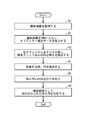
- FIG. 2 is a flowchart showing the operation of the object detection device 1.
- the camera 200 acquires the captured image (step S1), inputs the captured image to the CNN 130, and the CNN 130 outputs W ⁇ H ⁇ (5 ⁇ (1 + 2N) + C) dimensional object estimation data (step S2).
- the object detection unit 140 classifies the grid cells into classes, removes the OBs and PBs of the background grid cells (step S3), and overlaps with the BBs (OBs and PBs of each PB) of the grid cells having a higher reliability score. BB (OB and each PB) having a high value is removed (step S4).
- the association unit 40 associates the remaining OB with each PB (step S5), and saves the associated OB and each PB as an object detection result 121 (step S6).
- a point that protrudes from other parts or a point that is recessed from other parts is defined as a key point.
- the object model does not have to be three-dimensional, and may be a two-dimensional object model.
- control unit 110 is a computer system composed of a CPU, ROM, RAM, and the like, but a part or all of each processing unit is a system LSI (Large Scale Integration:). It may be composed of a large-scale integrated circuit).
- system LSI Large Scale Integration:
- This disclosure is useful as an object detection device mounted on a surveillance camera system or an in-vehicle camera system.
Landscapes
- Engineering & Computer Science (AREA)
- Theoretical Computer Science (AREA)
- Physics & Mathematics (AREA)
- General Physics & Mathematics (AREA)
- Computer Vision & Pattern Recognition (AREA)
- Multimedia (AREA)
- Evolutionary Computation (AREA)
- Software Systems (AREA)
- General Health & Medical Sciences (AREA)
- Health & Medical Sciences (AREA)
- Artificial Intelligence (AREA)
- Medical Informatics (AREA)
- Computing Systems (AREA)
- Databases & Information Systems (AREA)
- Life Sciences & Earth Sciences (AREA)
- Probability & Statistics with Applications (AREA)
- Geometry (AREA)
- Evolutionary Biology (AREA)
- Bioinformatics & Computational Biology (AREA)
- Bioinformatics & Cheminformatics (AREA)
- Biodiversity & Conservation Biology (AREA)
- Biomedical Technology (AREA)
- Molecular Biology (AREA)
- Image Analysis (AREA)
Priority Applications (2)
| Application Number | Priority Date | Filing Date | Title |
|---|---|---|---|
| US18/000,338 US12475676B2 (en) | 2020-06-05 | 2021-05-24 | Object detection method, object detection device, and program |
| JP2022528753A JP7251692B2 (ja) | 2020-06-05 | 2021-05-24 | オブジェクト検出方法、オブジェクト検出装置及びプログラム |
Applications Claiming Priority (2)
| Application Number | Priority Date | Filing Date | Title |
|---|---|---|---|
| JP2020098325 | 2020-06-05 | ||
| JP2020-098325 | 2020-06-05 |
Publications (1)
| Publication Number | Publication Date |
|---|---|
| WO2021246217A1 true WO2021246217A1 (ja) | 2021-12-09 |
Family
ID=78831050
Family Applications (1)
| Application Number | Title | Priority Date | Filing Date |
|---|---|---|---|
| PCT/JP2021/019555 Ceased WO2021246217A1 (ja) | 2020-06-05 | 2021-05-24 | オブジェクト検出方法、オブジェクト検出装置及びプログラム |
Country Status (3)
| Country | Link |
|---|---|
| US (1) | US12475676B2 (https=) |
| JP (1) | JP7251692B2 (https=) |
| WO (1) | WO2021246217A1 (https=) |
Cited By (2)
| Publication number | Priority date | Publication date | Assignee | Title |
|---|---|---|---|---|
| CN115482556A (zh) * | 2022-09-20 | 2022-12-16 | 百果园技术(新加坡)有限公司 | 关键点检测模型训练及虚拟角色驱动的方法和对应的装置 |
| JP2025520406A (ja) * | 2022-06-13 | 2025-07-03 | ソウル ナショナル ユニバーシティ ホスピタル | 医療情報を抽出する装置及び方法 |
Families Citing this family (2)
| Publication number | Priority date | Publication date | Assignee | Title |
|---|---|---|---|---|
| US12482130B2 (en) * | 2019-12-09 | 2025-11-25 | Konica Minolta, Inc. | Object detection method and object detection device |
| US12586198B2 (en) * | 2022-02-18 | 2026-03-24 | Techcyte, Inc. | Image analysis for identifying objects and classifying background exclusions |
Citations (2)
| Publication number | Priority date | Publication date | Assignee | Title |
|---|---|---|---|---|
| JP2006202135A (ja) * | 2005-01-21 | 2006-08-03 | Univ Of Tokushima | パターン検出装置、パターン検出方法、パターン検出プログラム及びコンピュータで読み取り可能な記録媒体並びに記録した機器 |
| JP2014109555A (ja) * | 2012-12-04 | 2014-06-12 | Nippon Telegr & Teleph Corp <Ntt> | 点群解析処理装置、点群解析処理方法及びプログラム |
Family Cites Families (10)
| Publication number | Priority date | Publication date | Assignee | Title |
|---|---|---|---|---|
| US8274508B2 (en) * | 2011-02-14 | 2012-09-25 | Mitsubishi Electric Research Laboratories, Inc. | Method for representing objects with concentric ring signature descriptors for detecting 3D objects in range images |
| US11288472B2 (en) * | 2011-08-30 | 2022-03-29 | Digimarc Corporation | Cart-based shopping arrangements employing probabilistic item identification |
| US11348269B1 (en) * | 2017-07-27 | 2022-05-31 | AI Incorporated | Method and apparatus for combining data to construct a floor plan |
| US11797854B2 (en) * | 2019-07-08 | 2023-10-24 | Sony Semiconductor Solutions Corporation | Image processing device, image processing method and object recognition system |
| CN113051969A (zh) * | 2019-12-26 | 2021-06-29 | 深圳市超捷通讯有限公司 | 物件识别模型训练方法及车载装置 |
| US11257298B2 (en) * | 2020-03-18 | 2022-02-22 | Adobe Inc. | Reconstructing three-dimensional scenes in a target coordinate system from multiple views |
| US11574492B2 (en) * | 2020-09-02 | 2023-02-07 | Smart Engines Service, LLC | Efficient location and identification of documents in images |
| US12205264B2 (en) * | 2020-10-15 | 2025-01-21 | Cognex Corporation | System and method for extracting and measuring shapes of objects having curved surfaces with a vision system |
| CN112884760B (zh) * | 2021-03-17 | 2023-09-26 | 东南大学 | 近水桥梁多类型病害智能检测方法与无人船设备 |
| CA3215397A1 (en) * | 2021-04-16 | 2022-10-20 | Tomas FILLER | Methods and arrangements to aid recycling |
-
2021
- 2021-05-24 WO PCT/JP2021/019555 patent/WO2021246217A1/ja not_active Ceased
- 2021-05-24 JP JP2022528753A patent/JP7251692B2/ja active Active
- 2021-05-24 US US18/000,338 patent/US12475676B2/en active Active
Patent Citations (2)
| Publication number | Priority date | Publication date | Assignee | Title |
|---|---|---|---|---|
| JP2006202135A (ja) * | 2005-01-21 | 2006-08-03 | Univ Of Tokushima | パターン検出装置、パターン検出方法、パターン検出プログラム及びコンピュータで読み取り可能な記録媒体並びに記録した機器 |
| JP2014109555A (ja) * | 2012-12-04 | 2014-06-12 | Nippon Telegr & Teleph Corp <Ntt> | 点群解析処理装置、点群解析処理方法及びプログラム |
Cited By (2)
| Publication number | Priority date | Publication date | Assignee | Title |
|---|---|---|---|---|
| JP2025520406A (ja) * | 2022-06-13 | 2025-07-03 | ソウル ナショナル ユニバーシティ ホスピタル | 医療情報を抽出する装置及び方法 |
| CN115482556A (zh) * | 2022-09-20 | 2022-12-16 | 百果园技术(新加坡)有限公司 | 关键点检测模型训练及虚拟角色驱动的方法和对应的装置 |
Also Published As
| Publication number | Publication date |
|---|---|
| JP7251692B2 (ja) | 2023-04-04 |
| JPWO2021246217A1 (https=) | 2021-12-09 |
| US12475676B2 (en) | 2025-11-18 |
| US20240029394A1 (en) | 2024-01-25 |
Similar Documents
| Publication | Publication Date | Title |
|---|---|---|
| Xiong et al. | Transferable two-stream convolutional neural network for human action recognition | |
| JP7251692B2 (ja) | オブジェクト検出方法、オブジェクト検出装置及びプログラム | |
| US7912253B2 (en) | Object recognition method and apparatus therefor | |
| JP4709723B2 (ja) | 姿勢推定装置及びその方法 | |
| CN106845487B (zh) | 一种端到端的车牌识别方法 | |
| JP4743823B2 (ja) | 画像処理装置、撮像装置、画像処理方法 | |
| CN110909651A (zh) | 视频主体人物的识别方法、装置、设备及可读存储介质 | |
| JP7294454B2 (ja) | オブジェクト検出方法及びオブジェクト検出装置 | |
| CN106951840A (zh) | 一种人脸特征点检测方法 | |
| CN108764107A (zh) | 基于人体骨架序列的行为与身份联合识别方法及装置 | |
| JP2008059197A (ja) | 画像照合装置、画像照合方法、コンピュータプログラム及び記憶媒体 | |
| CN102087703A (zh) | 确定正面的脸部姿态的方法 | |
| CN110458128A (zh) | 一种姿态特征获取方法、装置、设备及存储介质 | |
| CN112861785A (zh) | 一种基于实例分割和图像修复的带遮挡行人重识别方法 | |
| US12315173B2 (en) | Image processing system, image processing method, and storage medium for associating moving objects in images | |
| JP2012243285A (ja) | 特徴点位置決定装置、特徴点位置決定方法及びプログラム | |
| Zarkasi et al. | Weightless Neural Networks Face Recognition Learning Process for Binary Facial Pattern | |
| CN120431640A (zh) | 一种基于超图的手语识别方法及装置 | |
| CN117079305B (zh) | 姿态估计方法、姿态估计装置以及计算机可读存储介质 | |
| CN119841105A (zh) | 码垛机控制系统 | |
| Fomin et al. | Study of using deep learning nets for mark detection in space docking control images | |
| WO2022107548A1 (ja) | 3次元骨格検出方法及び3次元骨格検出装置 | |
| WO2023119969A1 (ja) | 物体追跡方法及び物体追跡装置 | |
| Anitta et al. | CNN—Forest based person identification and head pose estimation for AI based applications | |
| WO2023119968A1 (ja) | 3次元座標算出方法及び3次元座標算出装置 |
Legal Events
| Date | Code | Title | Description |
|---|---|---|---|
| 121 | Ep: the epo has been informed by wipo that ep was designated in this application |
Ref document number: 21818711 Country of ref document: EP Kind code of ref document: A1 |
|
| ENP | Entry into the national phase |
Ref document number: 2022528753 Country of ref document: JP Kind code of ref document: A |
|
| WWE | Wipo information: entry into national phase |
Ref document number: 18000338 Country of ref document: US |
|
| NENP | Non-entry into the national phase |
Ref country code: DE |
|
| 122 | Ep: pct application non-entry in european phase |
Ref document number: 21818711 Country of ref document: EP Kind code of ref document: A1 |
|
| WWG | Wipo information: grant in national office |
Ref document number: 18000338 Country of ref document: US |