WO2021246179A1 - 車両制御装置 - Google Patents
車両制御装置 Download PDFInfo
- Publication number
- WO2021246179A1 WO2021246179A1 PCT/JP2021/019036 JP2021019036W WO2021246179A1 WO 2021246179 A1 WO2021246179 A1 WO 2021246179A1 JP 2021019036 W JP2021019036 W JP 2021019036W WO 2021246179 A1 WO2021246179 A1 WO 2021246179A1
- Authority
- WO
- WIPO (PCT)
- Prior art keywords
- control device
- value
- wheel
- index value
- motor
- Prior art date
Links
- 230000005540 biological transmission Effects 0.000 description 11
- 238000000034 method Methods 0.000 description 9
- 230000006870 function Effects 0.000 description 5
- 238000012545 processing Methods 0.000 description 5
- 238000010586 diagram Methods 0.000 description 4
- 230000000694 effects Effects 0.000 description 4
- 230000009471 action Effects 0.000 description 3
- PXHVJJICTQNCMI-UHFFFAOYSA-N Nickel Chemical compound [Ni] PXHVJJICTQNCMI-UHFFFAOYSA-N 0.000 description 2
- 238000012986 modification Methods 0.000 description 2
- 230000004048 modification Effects 0.000 description 2
- 230000008569 process Effects 0.000 description 2
- 239000007787 solid Substances 0.000 description 2
- UFHFLCQGNIYNRP-UHFFFAOYSA-N Hydrogen Chemical compound [H][H] UFHFLCQGNIYNRP-UHFFFAOYSA-N 0.000 description 1
- HBBGRARXTFLTSG-UHFFFAOYSA-N Lithium ion Chemical compound [Li+] HBBGRARXTFLTSG-UHFFFAOYSA-N 0.000 description 1
- 238000006243 chemical reaction Methods 0.000 description 1
- 238000002485 combustion reaction Methods 0.000 description 1
- 230000000295 complement effect Effects 0.000 description 1
- 238000007796 conventional method Methods 0.000 description 1
- 230000005669 field effect Effects 0.000 description 1
- 229910052739 hydrogen Inorganic materials 0.000 description 1
- 239000001257 hydrogen Substances 0.000 description 1
- 229910001416 lithium ion Inorganic materials 0.000 description 1
- 238000013507 mapping Methods 0.000 description 1
- 230000007246 mechanism Effects 0.000 description 1
- 229910052759 nickel Inorganic materials 0.000 description 1
- 239000004065 semiconductor Substances 0.000 description 1
- 230000001360 synchronised effect Effects 0.000 description 1
Images


Classifications
-
- B—PERFORMING OPERATIONS; TRANSPORTING
- B60—VEHICLES IN GENERAL
- B60L—PROPULSION OF ELECTRICALLY-PROPELLED VEHICLES; SUPPLYING ELECTRIC POWER FOR AUXILIARY EQUIPMENT OF ELECTRICALLY-PROPELLED VEHICLES; ELECTRODYNAMIC BRAKE SYSTEMS FOR VEHICLES IN GENERAL; MAGNETIC SUSPENSION OR LEVITATION FOR VEHICLES; MONITORING OPERATING VARIABLES OF ELECTRICALLY-PROPELLED VEHICLES; ELECTRIC SAFETY DEVICES FOR ELECTRICALLY-PROPELLED VEHICLES
- B60L3/00—Electric devices on electrically-propelled vehicles for safety purposes; Monitoring operating variables, e.g. speed, deceleration or energy consumption
- B60L3/0023—Detecting, eliminating, remedying or compensating for drive train abnormalities, e.g. failures within the drive train
- B60L3/0038—Detecting, eliminating, remedying or compensating for drive train abnormalities, e.g. failures within the drive train relating to sensors
-
- B—PERFORMING OPERATIONS; TRANSPORTING
- B60—VEHICLES IN GENERAL
- B60L—PROPULSION OF ELECTRICALLY-PROPELLED VEHICLES; SUPPLYING ELECTRIC POWER FOR AUXILIARY EQUIPMENT OF ELECTRICALLY-PROPELLED VEHICLES; ELECTRODYNAMIC BRAKE SYSTEMS FOR VEHICLES IN GENERAL; MAGNETIC SUSPENSION OR LEVITATION FOR VEHICLES; MONITORING OPERATING VARIABLES OF ELECTRICALLY-PROPELLED VEHICLES; ELECTRIC SAFETY DEVICES FOR ELECTRICALLY-PROPELLED VEHICLES
- B60L15/00—Methods, circuits, or devices for controlling the traction-motor speed of electrically-propelled vehicles
- B60L15/20—Methods, circuits, or devices for controlling the traction-motor speed of electrically-propelled vehicles for control of the vehicle or its driving motor to achieve a desired performance, e.g. speed, torque, programmed variation of speed
- B60L15/2036—Electric differentials, e.g. for supporting steering vehicles
-
- B—PERFORMING OPERATIONS; TRANSPORTING
- B60—VEHICLES IN GENERAL
- B60L—PROPULSION OF ELECTRICALLY-PROPELLED VEHICLES; SUPPLYING ELECTRIC POWER FOR AUXILIARY EQUIPMENT OF ELECTRICALLY-PROPELLED VEHICLES; ELECTRODYNAMIC BRAKE SYSTEMS FOR VEHICLES IN GENERAL; MAGNETIC SUSPENSION OR LEVITATION FOR VEHICLES; MONITORING OPERATING VARIABLES OF ELECTRICALLY-PROPELLED VEHICLES; ELECTRIC SAFETY DEVICES FOR ELECTRICALLY-PROPELLED VEHICLES
- B60L2220/00—Electrical machine types; Structures or applications thereof
- B60L2220/40—Electrical machine applications
- B60L2220/42—Electrical machine applications with use of more than one motor
-
- B—PERFORMING OPERATIONS; TRANSPORTING
- B60—VEHICLES IN GENERAL
- B60L—PROPULSION OF ELECTRICALLY-PROPELLED VEHICLES; SUPPLYING ELECTRIC POWER FOR AUXILIARY EQUIPMENT OF ELECTRICALLY-PROPELLED VEHICLES; ELECTRODYNAMIC BRAKE SYSTEMS FOR VEHICLES IN GENERAL; MAGNETIC SUSPENSION OR LEVITATION FOR VEHICLES; MONITORING OPERATING VARIABLES OF ELECTRICALLY-PROPELLED VEHICLES; ELECTRIC SAFETY DEVICES FOR ELECTRICALLY-PROPELLED VEHICLES
- B60L2240/00—Control parameters of input or output; Target parameters
- B60L2240/40—Drive Train control parameters
- B60L2240/42—Drive Train control parameters related to electric machines
- B60L2240/421—Speed
-
- B—PERFORMING OPERATIONS; TRANSPORTING
- B60—VEHICLES IN GENERAL
- B60L—PROPULSION OF ELECTRICALLY-PROPELLED VEHICLES; SUPPLYING ELECTRIC POWER FOR AUXILIARY EQUIPMENT OF ELECTRICALLY-PROPELLED VEHICLES; ELECTRODYNAMIC BRAKE SYSTEMS FOR VEHICLES IN GENERAL; MAGNETIC SUSPENSION OR LEVITATION FOR VEHICLES; MONITORING OPERATING VARIABLES OF ELECTRICALLY-PROPELLED VEHICLES; ELECTRIC SAFETY DEVICES FOR ELECTRICALLY-PROPELLED VEHICLES
- B60L2240/00—Control parameters of input or output; Target parameters
- B60L2240/40—Drive Train control parameters
- B60L2240/42—Drive Train control parameters related to electric machines
- B60L2240/423—Torque
-
- B—PERFORMING OPERATIONS; TRANSPORTING
- B60—VEHICLES IN GENERAL
- B60L—PROPULSION OF ELECTRICALLY-PROPELLED VEHICLES; SUPPLYING ELECTRIC POWER FOR AUXILIARY EQUIPMENT OF ELECTRICALLY-PROPELLED VEHICLES; ELECTRODYNAMIC BRAKE SYSTEMS FOR VEHICLES IN GENERAL; MAGNETIC SUSPENSION OR LEVITATION FOR VEHICLES; MONITORING OPERATING VARIABLES OF ELECTRICALLY-PROPELLED VEHICLES; ELECTRIC SAFETY DEVICES FOR ELECTRICALLY-PROPELLED VEHICLES
- B60L50/00—Electric propulsion with power supplied within the vehicle
- B60L50/10—Electric propulsion with power supplied within the vehicle using propulsion power supplied by engine-driven generators, e.g. generators driven by combustion engines
- B60L50/14—Electric propulsion with power supplied within the vehicle using propulsion power supplied by engine-driven generators, e.g. generators driven by combustion engines using DC generators and AC motors
-
- Y—GENERAL TAGGING OF NEW TECHNOLOGICAL DEVELOPMENTS; GENERAL TAGGING OF CROSS-SECTIONAL TECHNOLOGIES SPANNING OVER SEVERAL SECTIONS OF THE IPC; TECHNICAL SUBJECTS COVERED BY FORMER USPC CROSS-REFERENCE ART COLLECTIONS [XRACs] AND DIGESTS
- Y02—TECHNOLOGIES OR APPLICATIONS FOR MITIGATION OR ADAPTATION AGAINST CLIMATE CHANGE
- Y02T—CLIMATE CHANGE MITIGATION TECHNOLOGIES RELATED TO TRANSPORTATION
- Y02T10/00—Road transport of goods or passengers
- Y02T10/60—Other road transportation technologies with climate change mitigation effect
- Y02T10/72—Electric energy management in electromobility
Definitions
- the present disclosure relates to a vehicle control device that controls seizure of the differential device.
- the average value of the rotation speeds (rotational speeds) of the left and right wheels distributed by the differential device matches the rotation speeds (input rotation speeds) input to the differential device. Therefore, the difference rotation speed of the differential device can be obtained by measuring at least two types of rotation speeds among the rotation speed of the left wheel, the rotation speed of the right wheel, and the input rotation speed.
- the wheel speed sensor that measures the rotation speeds of the left and right wheels fails, it is difficult to obtain an appropriate difference rotation speed, and it may not be possible to prevent the occurrence of seizure.
- One of the purposes of this case is to provide a vehicle control device which was devised in view of the above-mentioned problems and can suppress the seizure of the differential device when the wheel speed sensor fails. .. Not limited to this purpose, it is also an action and effect derived from each configuration shown in the "form for carrying out the invention" described later, and it is also another purpose of this case to exert an action and effect which cannot be obtained by the conventional technique. Can be positioned.
- the disclosed vehicle control device includes a drive source mounted on the vehicle, a differential device that distributes the driving force generated by the drive source to the right drive wheel and the left drive wheel, and the rotation speed of the drive source.
- a speed sensor for detecting the above and a pair of wheel speed sensors for detecting the rotational speeds of the right drive wheel and the left drive wheel are provided. Further, when at least one of the pair of wheel speed sensors fails, an index value having a value obtained by multiplying the rotation speed of the drive source by a predetermined coefficient is set, and an index value is output from the drive source based on the index value. It is equipped with a control device that controls the torque to be generated.
- This is an example of a map stored in the control device of FIG. 1, and is a map that defines the relationship between the rotational speed difference (index value) in the front wheel differential device and the torque limit value of the front wheel motor.
- This is an example of a map stored in the control device of FIG. 1, and is a map that defines the relationship between the rotational speed difference (index value) in the rear wheel differential device and the torque limit value of the rear wheel motor.
- It is a flowchart which shows the flow of the control performed by the control apparatus of FIG.
- the vehicle 1 to which the vehicle control device as an embodiment is applied will be described with reference to FIGS. 1 to 5.
- a motor 2 and a differential device 3 are mounted on the vehicle 1.
- the motor 2 is a drive source of the vehicle 1 that generates the driving force of the vehicle 1 by using the electric power stored in the battery 6.
- the motor 2 is, for example, a three-phase AC type synchronous motor, and is connected to the battery 6 via an inverter 5.
- the vehicle 1 shown in FIG. 1 is individually equipped with a front wheel motor 2 (front motor) and a rear wheel motor 2 (rear motor), but one of them may be omitted or simply.
- the device configuration may be such that four wheels are driven by one motor 2.
- the differential device 3 is a device that distributes the driving force generated by the motor 2 to the left and right drive wheels, and is interposed between the left wheel shaft and the right wheel shaft.
- a transmission 4 is interposed in the transmission path of the driving force connecting the motor 2 and the differential device 3.
- the transmission 4 is a device that shifts (decelerates or accelerates) the driving force output from the motor 2, and includes, for example, a plurality of gear trains, a planetary gear mechanism, and the like.
- the gear ratio (that is, input rotation speed ⁇ output rotation speed), which is the ratio of the input rotation speed to the output rotation speed of the transmission 4, may be a fixed value or a variable value. Information on the gear ratio of the transmission 4 is grasped by the control device 10 (ECU) described later.
- the battery 6 is, for example, a lithium ion battery or a nickel hydrogen battery, and is a secondary battery capable of supplying a high voltage DC current of several hundred volts.
- the inverter 5 is a power conversion device for converting DC power on the battery 6 side and AC power on the motor 2 side, and is interposed on a power line connecting the battery 6 and the motor 2.
- the inverter 5 contains an inverter circuit including switch elements such as an IGBT (Insulated Gate Bipolar Transistor) and a MOSFET (Metal-Oxide-Semiconductor Field-Effect Transistor).
- the output (torque) of the motor 2 is controlled by controlling the operating state (on / off timing and drive frequency) of the inverter 5.
- the operating state of the inverter 5 is controlled by the control device 10.
- the control device 10 is an electronic control device (computer) that controls the torque output from the motor 2 by managing the on / off state of the switch element built in the inverter 5.
- a processor central processing unit
- a memory main memory
- a storage device storage
- an interface device and the like are built in the control device 10, and these communicate with each other via an internal bus. Can be connected.
- a motor speed sensor 7, a right wheel speed sensor 8, and a left wheel speed sensor 9 are connected to the control device 10, and a vehicle speed sensor and an accelerator opening sensor (not shown) are also connected to the control device 10.
- the motor speed sensor 7 is a speed sensor that detects the motor rotation speed (rotational speed output from the motor 2). Further, the right wheel speed sensor 8 is a wheel speed sensor that detects the rotation speed (right wheel speed) of the drive wheel on the right side of the differential device 3, and the left wheel speed sensor 9 is a drive on the left side of the differential device 3. It is a wheel speed sensor that detects the rotation speed of the wheel (left wheel speed). Information on various rotation speeds detected by these sensors 7 to 9 is input to the control device 10.
- the vehicle speed sensor is a sensor that detects the traveling speed (vehicle speed) of the vehicle 1
- the accelerator opening degree sensor is a sensor that detects the amount of depression of the accelerator pedal (accelerator opening degree). Further, in FIG. 1, sensors 7 to 9 are provided on the front side and the rear side, respectively, but one of them may be omitted.
- the magnitude of the torque output from the motor 2 is set according to the vehicle speed and the accelerator opening.
- the torque of the motor 2 may become excessive.
- seizure may occur inside the differential device 3. Therefore, the control device 10 sets the torque limit value of the motor 2 and controls the inverter 5 so that the torque actually output from the motor 2 does not exceed the torque limit value.
- the output of each of the front wheel motor 2 and the rear wheel motor 2 is controlled based on individually set torque limit values.
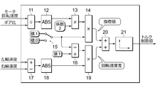
- FIG. 3 is a block diagram for explaining the processing content for setting the torque limit value.
- the torque limit value is set by using different methods depending on whether the wheel speed sensors 8 and 9 are out of order and not. For example, when the pair of wheel speed sensors 8 and 9 provided on the left and right sides of the same differential device 3 are not out of order, the torque limit value is set based on the difference between the left and right drive wheel rotation speeds. On the other hand, when at least one of the pair of wheel speed sensors 8 and 9 provided on the left and right of the same differential device 3 is out of order, the torque limit value is set based on the motor rotation speed.
- the former setting method corresponds to the processing content shown in the lower part in FIG. 3, and the latter setting method corresponds to the processing content shown in the upper part in FIG.
- the presence or absence of a failure in the wheel speed sensors 8 and 9 may be determined based on the signals transmitted from the wheel speed sensors 8 and 9, or the determination result in a failure determination device (not shown) may be diverted. ..
- the divider 11 shown in FIG. 3 calculates a value obtained by dividing the motor rotation speed by the gear ratio of the transmission 4 (a value obtained by multiplying the reciprocal of the gear ratio of the transmission 4).
- the value calculated here corresponds to the rotation speed output from the transmission 4, in other words, corresponds to the rotation speed input to the differential device 3.
- the value calculated by the divider 11 is input to the multiplier 13 after the sign is removed via the absolute value calculator 12.
- the multiplier 13 calculates an index value obtained by multiplying the input value by a predetermined coefficient.
- the value of the coefficient is set to a value close to 2, for example, (for example, in the range of 1.9 to 2.1).
- the value of this coefficient is preferably set to a value of 2 or more (for example, in the range of 2.0 to 2.1), and more preferably set to 2.
- the value calculated by the multiplier 13 is input to the multiplier 14.
- the multiplier 14 calculates the product of the value calculated by the multiplier 13 and the output of the failure determination device 15.
- the failure determiner 15 outputs 1 when at least one of the pair of wheel speed sensors 8 and 9 has failed, and outputs 0 when neither of the pair of wheel speed sensors 8 and 9 has failed. do. Therefore, when neither of the pair of wheel speed sensors 8 and 9 has failed, the output of the multiplier 14 becomes 0 regardless of the magnitude of the output of the multiplier 13.
- the output of the multiplier 13 is output as it is from the multiplier 14 only when at least one of the pair of wheel speed sensors 8 and 9 is out of order.
- the multiplier 14 functions to set an index value having a value obtained by multiplying the motor rotation speed by a predetermined coefficient when at least one of the pair of wheel speed sensors 8 and 9 fails. ..
- the value calculated by the multiplier 14 is transmitted to the adder 20.
- the subtractor 17 shown in FIG. 3 calculates a value obtained by subtracting the right wheel speed from the left wheel speed (a value obtained by adding the left wheel speed and the complement of the right wheel speed).
- the value calculated here corresponds to the difference in rotational speed between the left and right sides of the differential device 3.
- the value calculated by the subtractor 17 is input to the multiplier 19 after the sign is removed via the absolute value calculator 18.
- the multiplier 19 outputs the product of the output of the absolute value calculator 18 and the output of the subtractor 16.
- the subtractor 16 outputs a value obtained by inverting the output of the failure determination device 15.
- the subtractor 16 outputs 1 when the failure determination device 15 outputs 0, and outputs 0 when the failure determination device 15 outputs 1. Therefore, when at least one of the pair of wheel speed sensors 8 and 9 is out of order, the output of the multiplier 19 becomes 0 regardless of the magnitude of the output of the absolute value calculator 18. Only when neither of the pair of wheel speed sensors 8 and 9 has failed, the output of the absolute value calculator 18 is output from the multiplier 19 as it is. In this way, the multiplier 19 functions to calculate the difference in rotational speed between the left and right drive wheels when the pair of wheel speed sensors 8 and 9 are not out of order. The value calculated by the multiplier 19 is transmitted to the adder 20.
- the adder 20 calculates the sum of the output of the multiplier 14 and the output of the multiplier 19.
- the output of the multiplier 14 is 0 when the pair of wheel speed sensors 8 and 9 are not failed, and the output of the multiplier 19 is 0 when the pair of wheel speed sensors 8 and 9 are failed. Therefore, the adder 20 functions to accept one of the multipliers 14 and 19 that outputs a non-zero value as it is, and to pass the information to the downstream side.
- the value output from the adder 20 is input to the limit value setting device 21.
- the limit value setting device 21 outputs a torque limit value corresponding to a value (index value or rotation speed difference) transmitted from the adder 20.
- the limit value setter 21 at least a map or a mathematical formula that defines the correspondence between the index value set by the multiplier 14 and the torque limit value is stored in advance.
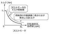
- FIG. 4A is a graph illustrating the relationship between the torque limit value and the index value in the front wheel motor 2.
- the solid line in the graph represents the torque limit value, and the broken line represents the torque at which seizure may occur in the front wheel differential device 3.
- the broken line graph shows the relationship in which the torque on the vertical axis is almost inversely proportional to the index value on the horizontal axis.
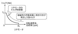
- FIG. 4B is a graph illustrating the relationship between the torque limit value and the index value in the rear wheel motor 2.
- the solid line in the graph represents the torque limit value, and the broken line represents the torque at which seizure may occur in the rear wheel differential device 3.
- the rear wheel motor 2 and the differential device 3 are provided separately from the front wheel motor 2 and the differential device 3, and do not necessarily have the same characteristics as the front wheel motor 2 and the differential device 3. Therefore, the torque limit value of the rear wheel motor 2 can be set separately from the torque limit value of the front wheel motor 2.
- the shapes of the solid and dashed graphs in FIG. 4B do not necessarily match the shapes of the solid and dashed graphs in FIG. 4A.
- the maximum value T 2 of the torque limit value in FIG. 4B is different from the maximum value T 1 of the torque limit value in FIG. 4A.
- the maximum value R 2 of the index value in FIG. 4B is different from the maximum value R 1 of the index value in FIG. 4A.
- the graph of the torque limit value shown by the solid line is set at least below (on the left side) of the graph of the broken line. Therefore, when a rotation speed difference is input to the limit value setting device 21, the torque limit value corresponding to the rotation speed difference is set to prevent a situation in which an excessive torque is output from the motor 2. Therefore, the occurrence of seizure in the differential device 3 is suppressed. Further, when an index value is input to the limit value setting device 21, the index value has a value corresponding to a rotation speed that is substantially double the rotation speed of the motor 2. On the other hand, it is known that the difference in rotation speed that can occur in the differential device 3 is at most twice the input rotation speed.
- the index value referred to here has a value corresponding to the maximum rotation speed difference that can occur in the differential device 3. Therefore, by setting the torque limit value using the index value instead of the rotation speed difference, the situation where an excessive torque is output from the motor 2 is prevented, and the seizure in the differential device 3 is sure to occur. Is suppressed.
- FIG. 5 is a flowchart showing the flow of control performed by the control device 10.
- step A1 information on the motor rotation speed detected by the motor speed sensor 7 and information on the left and right wheel speeds detected by the pair of left and right wheel speed sensors 8 and 9 are input to the control device 10. Further, when the gear ratio of the transmission 4 is variable, information on the value is also input to the control device 10.
- step A2 it is determined whether or not at least one of the pair of wheel speed sensors 8 and 9 is out of order. As shown in FIG. 1, when a pair of left and right wheel speed sensors 8 and 9 are provided on each of the front wheel side and the rear wheel side, the front wheel side and the rear wheel side are distinguished from each other and fail independently of each other. The presence or absence of is determined.
- step A2 If it is determined in step A2 that at least one of the wheel speed sensors 8 and 9 has a failure, the process proceeds to step A3, and an index value is set based on the motor rotation speed.
- the index value is calculated, for example, by multiplying the absolute value of the value obtained by dividing the motor rotation speed by the gear ratio of the transmission 4 by a predetermined coefficient.
- the index value is used as an argument of the map as shown in FIGS. 4A and 4B, and the torque limit value corresponding to the index value is acquired.
- step A5 the operating state of the inverter 5 is controlled so that the torque of the motor 2 does not exceed the torque limit value. As described above, even if the wheel speed sensors 8 and 9 are out of order, the torque of the motor 2 is appropriately limited, so that the occurrence of seizure in the differential device 3 is suppressed.
- step A6 If it is determined in step A2 that there is no failure in the wheel speed sensors 8 and 9, the process proceeds to step A6 and the actual rotation speed difference is calculated.
- the rotation speed difference is calculated as, for example, an absolute value obtained by subtracting the right wheel speed from the left wheel speed.
- step A7 the rotation speed difference is used as an argument of the map as shown in FIGS. 4A and 4B, and the torque limit value corresponding to the rotation speed difference is acquired.
- step A5 the operating state of the inverter 5 is controlled so that the torque of the motor 2 does not exceed the torque limit value. In this way, when the wheel speed sensors 8 and 9 are not out of order, the value of the rotational speed difference is calculated with high accuracy. Therefore, the torque of the motor 2 is appropriately limited, and the occurrence of seizure in the differential device 3 is suppressed.
- the vehicle control device detects the motor 2 mounted on the vehicle 1, the differential device 3 that distributes the driving force generated by the motor 2 to the left and right drive wheels, and the rotation speed of the motor 2.
- a pair of wheel speed sensors 8 and 9 for detecting the rotational speeds of the left and right drive wheels are provided. Further, in the vehicle control device, when at least one of the pair of wheel speed sensors 8 and 9 fails, an index value having a value obtained by multiplying the rotation speed of the motor 2 by a predetermined coefficient is set.
- a control device 10 for controlling the torque output from the motor 2 based on the index value is provided. With such a configuration, the torque of the motor 2 can be limited without using the information obtained by the wheel speed sensors 8 and 9, and the seizure of the differential device 3 at the time of failure of the wheel speed sensors 8 and 9 is suppressed. can.
- the index value set when at least one of the pair of wheel speed sensors 8 and 9 fails is, for example, twice or more the rotation speed input to the differential device 3.
- the index value can be set to a value corresponding to at least the maximum rotation speed difference that can occur in the differential device 3 (or a value higher than that). Therefore, the occurrence of seizure in the differential device 3 can be reliably suppressed.
- the index value is set so as to have a value twice the value obtained by dividing the motor rotation speed by the gear ratio. With such a setting, the index value becomes a value corresponding to the maximum rotation speed difference that can occur in the differential device 3, and the occurrence of seizure in the differential device 3 can be suppressed most efficiently and reliably. Considering the existence of control error and calculation error, it is technically significant to set the value of a predetermined coefficient slightly deviated from 2.
- a map defining the relationship between the index value and the torque limit value is used.
- this map By using this map and controlling the torque output from the motor 2 so as not to exceed the torque limit value of the magnitude corresponding to the index value, an excessive torque is input to the differential device 3. The situation can be easily avoided. Further, by mapping the relationship between the index value and the torque limit value, the torque limit value can be obtained quickly and easily, and the calculation load can be reduced. Therefore, for example, it is possible to suppress the occurrence of seizure due to the control delay of the motor 2.
- the motor 2 is used as the drive source of the vehicle 1, but the above vehicle control device is applied to a hybrid vehicle in which the motor 2 and an engine (internal combustion engine such as a gasoline engine or a diesel engine) are used in combination. It is also possible to apply. Further, the above-mentioned vehicle control device may be applied to an automobile in which only the engine is used as the drive source of the vehicle 1. Alternatively, the above-mentioned vehicle control device may be applied to a vehicle whose drive source is a motor generator (a device having both a function of an electric motor and a function of a generator) instead of the motor 2. At least, by setting an index value having a value obtained by multiplying the rotation speed of the drive source by a predetermined coefficient and controlling the torque output from the drive source based on the index value, the same effect as that of the above-described embodiment can be obtained. Play.
- the vehicle control device of the present disclosure it is possible to suppress seizure of the differential device when the wheel speed sensor fails.
Landscapes
- Engineering & Computer Science (AREA)
- Power Engineering (AREA)
- Transportation (AREA)
- Mechanical Engineering (AREA)
- Life Sciences & Earth Sciences (AREA)
- Sustainable Development (AREA)
- Sustainable Energy (AREA)
- Arrangement And Mounting Of Devices That Control Transmission Of Motive Force (AREA)
- Electric Propulsion And Braking For Vehicles (AREA)
- Retarders (AREA)
Abstract
ここで開示する車両制御装置は、車両(1)に搭載される駆動源(2)と、駆動源(2)で生成される駆動力を右の駆動輪と左の駆動輪とに分配する差動装置(3)と、駆動源(2)の回転速度を検出する速度センサ(7)と、前記右の駆動輪及び前記左の駆動輪の回転速度を検出する一対の車輪速センサ(8,9)とを備える。また、一対の車輪速センサ(8,9)の少なくとも一方が故障した場合に、駆動源(2)の回転速度に所定の係数を乗じた値を持つ指標値を設定し、指標値に基づいて駆動源(2)から出力されるトルクを制御する制御装置(10)を備える。
Description
本開示は、差動装置の焼き付きを抑制する制御を行う車両制御装置に関する。
従来、車両の左右輪間に差動装置が介装された車両において、差回転数の増大による焼き付きの発生を防止する技術が提案されている。例えば、左右の車輪軸の差回転数(回転速度差)が所定値以上である場合に、モータへの供給電流をゼロにし、あるいはモータを逆回転させることで差回転数を減少させる技術が知られている。このような制御により、差動装置の焼き付きが防止されうる(特許文献1参照)。
一般に、差動装置で分配される左右輪の回転数(回転速度)の平均値は、その差動装置に入力されている回転数(入力回転数)と一致する。したがって、左輪の回転数,右輪の回転数,入力回転数のうち、少なくとも二種類の回転数を計測することで、差動装置の差回転数を求めることができる。一方、左右輪の回転数を計測する車輪速センサが故障した場合には、適切な差回転数を求めることが難しく、焼き付きの発生を防止できないことがある。
本件の目的の一つは、上記のような課題に鑑みて創案されたものであり、車輪速センサの故障時における差動装置の焼き付きを抑制できるようにした車両制御装置を提供することである。この目的に限らず、後述する「発明を実施するための形態」に示す各構成から導き出される作用効果であって、従来の技術では得られない作用効果を奏することも、本件の他の目的として位置付けることができる。
開示の車両制御装置は、車両に搭載される駆動源と、前記駆動源で生成される駆動力を右の駆動輪と左の駆動輪とに分配する差動装置と、前記駆動源の回転速度を検出する速度センサと、前記右の駆動輪及び左の駆動輪の回転速度を検出する一対の車輪速センサとを備える。また、前記一対の車輪速センサの少なくとも一方が故障した場合に、前記駆動源の回転速度に所定の係数を乗じた値を持つ指標値を設定し、前記指標値に基づいて前記駆動源から出力されるトルクを制御する制御装置を備える。
本開示の技術によれば、車輪速センサの故障時における差動装置の焼き付きを抑制できる。
[1.構成]
図1~図5を参照して、実施例としての車両制御装置が適用された車両1について説明する。この車両1には、モータ2と差動装置3とが搭載される。モータ2は、バッテリ6に蓄えられた電力を利用して、車両1の駆動力を生成する車両1の駆動源である。モータ2は、例えば三相交流型の同期電動機であり、インバータ5を介してバッテリ6に接続される。図1に示す車両1には、前輪用のモータ2(フロントモータ)と後輪用のモータ2(リヤモータ)とが個別に搭載されているが、いずれか一方を省略してもよいし、単一のモータ2で四輪を駆動するような装置構成にしてもよい。
図1~図5を参照して、実施例としての車両制御装置が適用された車両1について説明する。この車両1には、モータ2と差動装置3とが搭載される。モータ2は、バッテリ6に蓄えられた電力を利用して、車両1の駆動力を生成する車両1の駆動源である。モータ2は、例えば三相交流型の同期電動機であり、インバータ5を介してバッテリ6に接続される。図1に示す車両1には、前輪用のモータ2(フロントモータ)と後輪用のモータ2(リヤモータ)とが個別に搭載されているが、いずれか一方を省略してもよいし、単一のモータ2で四輪を駆動するような装置構成にしてもよい。
差動装置3は、モータ2で生成される駆動力を左右の駆動輪に分配する装置であり、左輪軸と右輪軸との間に介装される。モータ2と差動装置3とをつなぐ駆動力の伝達経路には、変速機4が介装される。変速機4は、モータ2から出力される駆動力を変速(減速または増速)する装置であり、例えば複数のギヤ列や遊星歯車機構などが内蔵される。変速機4の出力回転速度に対する入力回転速度の比であるギア比(すなわち、入力回転速度÷出力回転速度)は固定値であってもよいし、可変値であってもよい。変速機4のギア比の情報は、後述する制御装置10(ECU)に把握される。
バッテリ6は、例えばリチウムイオン電池やニッケル水素電池であり、数百ボルトの高電圧直流電流を供給しうる二次電池である。また、インバータ5は、バッテリ6側の直流電力とモータ2側の交流電力とを変換するための電力変換装置であり、バッテリ6とモータ2とをつなぐ動力線上に介装される。インバータ5には、IGBT(Insulated Gate Bipolar Transistor)やMOSFET(Metal-Oxide-Semiconductor Field-Effect Transistor)などのスイッチ素子を含むインバータ回路が内蔵される。インバータ5の作動状態(オンオフのタイミングや駆動周波数)を制御することで、モータ2の出力(トルク)が制御される。
インバータ5の作動状態は、制御装置10によって制御される。制御装置10は、インバータ5に内蔵されたスイッチ素子のオンオフ状態を管理することで、モータ2から出力されるトルクを制御する電子制御装置(コンピュータ)である。制御装置10の内部には、図2に示すように、プロセッサ(中央処理装置),メモリ(メインメモリ),記憶装置(ストレージ),インタフェース装置などが内蔵され、内部バスを介してこれらが互いに通信可能に接続される。また、制御装置10には、モータ速度センサ7,右車輪速センサ8,左車輪速センサ9が接続されるとともに、図示しない車速センサやアクセル開度センサも接続される。
モータ速度センサ7は、モータ回転速度(モータ2から出力される回転速度)を検出する速度センサである。また、右車輪速センサ8は差動装置3よりも右側の駆動輪の回転速度(右車輪速)を検出する車輪速センサであり、左車輪速センサ9は差動装置3よりも左側の駆動輪の回転速度(左車輪速)を検出する車輪速センサである。これらのセンサ7~9で検出された各種回転速度の情報は、制御装置10に入力される。なお、車速センサは車両1の走行速度(車速)を検出するセンサであり、アクセル開度センサはアクセルペダルの踏み込み量(アクセル開度)を検出するセンサである。また、図1ではセンサ7~9がフロント側とリヤ側とのそれぞれに設けられているが、いずれか一方を省略してもよい。
モータ2から出力されるトルクの大きさは、車速やアクセル開度に応じて設定される。一方、車両1の走行状態によっては、モータ2のトルクが過大となる場合がある。例えば、左右の駆動輪の回転数差が大きくなったときには、差動装置3の内部に焼き付きが発生するおそれが生じる。そこで制御装置10は、モータ2のトルク制限値を設定するとともに、実際にモータ2から出力されるトルクがトルク制限値を超えないようにインバータ5を制御する。図1に示す車両1では、前輪用のモータ2と後輪用のモータ2との各々について、個別に設定されるトルク制限値に基づいて各々の出力が制御される。
図3は、トルク制限値を設定する処理内容を説明するためのブロック図である。トルク制限値は、車輪速センサ8,9が故障している場合と故障していない場合とで異なる手法が用いられて設定される。例えば、同一の差動装置3の左右に設けられた一対の車輪速センサ8,9が故障していない場合には、左右の駆動輪回転速度差に基づいてトルク制限値が設定される。一方、同一の差動装置3の左右に設けられた一対の車輪速センサ8,9の少なくともいずれかが故障している場合には、モータ回転速度に基づいてトルク制限値が設定される。前者の設定手法は、図3中で下方に示される処理内容に対応し、後者の設定手法は、図3中で上方に示される処理内容に対応する。なお、車輪速センサ8,9における故障の有無は、車輪速センサ8,9から伝達される信号に基づいて判断してもよいし、図示しない故障判定装置での判定結果を流用してもよい。
ここで、一対の車輪速センサ8,9の少なくともいずれかが故障している場合の設定手法について詳述する。図3中に示す除算器11は、モータ回転速度を変速機4のギア比で除した値(変速機4のギア比の逆数を乗算した値)を算出する。ここで算出される値は、変速機4から出力される回転速度に相当し、言い換えれば、差動装置3に入力される回転速度に相当する。除算器11で算出された値は、絶対値演算器12を介して符号を除去された後に、乗算器13に入力される。乗算器13は、入力された値に所定の係数を乗じた指標値を算出する。係数の値は、例えば2に近い値(例えば1.9~2.1の範囲内)に設定される。この係数の値は、好ましくは2以上の値(例えば2.0~2.1の範囲内)に設定され、より好ましくは2に設定される。乗算器13で算出された値は、乗算器14に入力される。
乗算器14は、乗算器13で算出された値と故障判定器15の出力との積を算出する。故障判定器15は、一対の車輪速センサ8,9の少なくともいずれかが故障している場合に1を出力し、一対の車輪速センサ8,9がいずれも故障していない場合に0を出力する。したがって、一対の車輪速センサ8,9がいずれも故障していない場合には、乗算器13の出力の大小にかかわらず、乗算器14の出力が0になる。一対の車輪速センサ8,9の少なくともいずれかが故障している場合にのみ、乗算器13の出力がそのまま乗算器14から出力される。このように、乗算器14は、一対の車輪速センサ8,9の少なくともいずれか一方が故障した場合に、モータ回転速度に所定の係数を乗じた値を持つ指標値を設定するように機能する。乗算器14で算出された値は、加算器20に伝達される。
続いて、一対の車輪速センサ8,9がいずれも故障していない場合の設定手法について詳述する。図3中に示す減算器17は、左輪速度から右輪速度を減じた値(左輪速度と右輪速度の補数とを加算した値)を算出する。ここで算出される値は、差動装置3における左右の回転速度差に相当する。減算器17で算出された値は、絶対値演算器18を介して符号を除去された後に、乗算器19に入力される。乗算器19は、絶対値演算器18の出力と減算器16の出力との積を出力する。減算器16は、故障判定器15の出力を反転させた値を出力する。
減算器16は、例えば故障判定器15が0を出力しているときには1を出力し、故障判定器15が1を出力しているときには0を出力する。したがって、一対の車輪速センサ8,9の少なくともいずれかが故障している場合には、絶対値演算器18の出力の大小にかかわらず、乗算器19の出力が0になる。一対の車輪速センサ8,9がいずれも故障していない場合にのみ、絶対値演算器18の出力がそのまま乗算器19から出力される。このように、乗算器19は、一対の車輪速センサ8,9が故障していない場合に、左右の駆動輪の回転速度差を算出するように機能する。乗算器19で算出された値は、加算器20に伝達される。
加算器20は、乗算器14の出力と乗算器19の出力との和を算出する。乗算器14の出力は一対の車輪速センサ8,9が故障していない場合は0であり、乗算器19の出力は一対の車輪速センサ8,9が故障している場合は0である。したがって、加算器20は、乗算器14,19のうち0でない値を出力している片方をそのまま受け入れるとともに、その情報を下流側へ渡すように機能する。加算器20から出力された値は、制限値設定器21に入力される。制限値設定器21は、加算器20から伝達される値(指標値または回転速度差)に対応するトルク制限値を出力する。制限値設定器21には、少なくとも乗算器14で設定された指標値とトルク制限値との対応関係を規定したマップや数式があらかじめ保存されている。
図4Aは、前輪用のモータ2におけるトルク制限値と指標値との関係を例示するグラフである。グラフ中の実線はトルク制限値を表し、破線は前輪用の差動装置3に焼き付きが発生しうるトルクを表している。破線のグラフは、縦軸のトルクが横軸の指標値に対してほぼ反比例する関係を示している。また、図4Bは、後輪用のモータ2におけるトルク制限値と指標値との関係を例示するグラフである。グラフ中の実線はトルク制限値を表し、破線は後輪用の差動装置3に焼き付きが発生しうるトルクを表している。
後輪用のモータ2及び差動装置3は、前輪用のモータ2及び差動装置3とは別に設けられ、必ずしも前輪用のモータ2及び差動装置3と同一の特性を持たない。したがって、後輪用のモータ2のトルク制限値は、前輪用のモータ2のトルク制限値とは別に設定されうる。図4Bにおける実線及び破線グラフの形状は、必ずしも図4Aにおける実線及び破線グラフの形状とは一致しない。また、図4Bにおけるトルク制限値の最大値T2は、図4Aにおけるトルク制限値の最大値T1とは相違する。同様に、図4Bにおける指標値の最大値R2は、図4Aにおける指標値の最大値R1とは相違する。
図4A、図4Bのいずれにおいても、実線で示すトルク制限値のグラフは、少なくとも破線のグラフよりも下方(左側)に設定される。したがって、制限値設定器21に回転速度差が入力された場合には、その回転速度差に対応するトルク制限値を設定することで、モータ2から過大なトルクが出力されるような事態が防止され、差動装置3での焼き付きの発生が抑制される。また、制限値設定器21に指標値が入力された場合、その指標値はモータ2の回転速度をほぼ二倍した回転速度に相当する値を持つ。一方、差動装置3に発生しうる回転速度差は、最大でも入力回転速度の二倍であることが知られている。つまり、ここでいう指標値は、差動装置3で発生しうる最大の回転速度差に相当する値を持つ。したがって、回転速度差の代わりに指標値を用いてトルク制限値を設定することで、モータ2から過大なトルクが出力されるような事態が防止され、差動装置3での焼き付きの発生が確実に抑制される。
[2.フローチャート]
図5は、制御装置10で実施される制御の流れを示すフローチャートである。
ステップA1では、モータ速度センサ7で検出されたモータ回転速度の情報や、左右一対の車輪速センサ8,9で検出された左右輪速度の情報が制御装置10に入力される。また、変速機4のギア比が可変である場合には、その値に関する情報も制御装置10に入力される。続くステップA2では、一対の車輪速センサ8,9の少なくともいずれかが故障しているか否かが判定される。図1に示すように、前輪側と後輪側とのそれぞれに左右一対の車輪速センサ8,9が設けられている場合には前輪側と後輪側とが区別され、互いに独立して故障の有無が判定される。
図5は、制御装置10で実施される制御の流れを示すフローチャートである。
ステップA1では、モータ速度センサ7で検出されたモータ回転速度の情報や、左右一対の車輪速センサ8,9で検出された左右輪速度の情報が制御装置10に入力される。また、変速機4のギア比が可変である場合には、その値に関する情報も制御装置10に入力される。続くステップA2では、一対の車輪速センサ8,9の少なくともいずれかが故障しているか否かが判定される。図1に示すように、前輪側と後輪側とのそれぞれに左右一対の車輪速センサ8,9が設けられている場合には前輪側と後輪側とが区別され、互いに独立して故障の有無が判定される。
ステップA2で車輪速センサ8,9の少なくとも一方に故障があると判定された場合には、ステップA3に進み、モータ回転速度に基づいて指標値が設定される。指標値は、例えばモータ回転速度を変速機4のギア比で除した値の絶対値に所定の係数を乗じることで算出される。続くステップA4では、図4A、図4Bに示すようなマップの引数として指標値が用いられ、指標値に対応するトルク制限値が取得される。その後、ステップA5において、モータ2のトルクがトルク制限値を超えないように、インバータ5の作動状態が制御される。このように、たとえ車輪速センサ8,9が故障していたとしても、モータ2のトルクが適切に制限されるため、差動装置3での焼き付きの発生が抑制される。
ステップA2で車輪速センサ8,9に故障がないと判定された場合には、ステップA6に進み、実際の回転速度差が算出される。回転速度差は、例えば左輪速度から右輪速度を減じた値の絶対値として算出される。続くステップA7では、図4A、図4Bに示すようなマップの引数として回転速度差が用いられ、回転速度差に対応するトルク制限値が取得される。その後、ステップA5において、モータ2のトルクがトルク制限値を超えないように、インバータ5の作動状態が制御される。このように、車輪速センサ8,9が故障していない場合には、回転速度差の値が精度よく算出される。したがって、モータ2のトルクが適切に制限され、差動装置3での焼き付きの発生が抑制される。
[3.作用,効果]
(1)上記の車両制御装置には、車両1に搭載されるモータ2と、モータ2で生成される駆動力を左右の駆動輪に分配する差動装置3と、モータ2の回転速度を検出するモータ速度センサ7と、左右の駆動輪の回転速度を検出する一対の車輪速センサ8,9とが設けられる。また、上記の車両制御装置には、一対の車輪速センサ8,9の少なくともいずれか一方が故障した場合に、モータ2の回転速度に所定の係数を乗じた値を持つ指標値を設定し、その指標値に基づいてモータ2から出力されるトルクを制御する制御装置10が設けられる。このような構成により、車輪速センサ8,9で得られる情報を用いることなく、モータ2のトルクを制限することができ、車輪速センサ8,9の故障時における差動装置3の焼き付きを抑制できる。
(1)上記の車両制御装置には、車両1に搭載されるモータ2と、モータ2で生成される駆動力を左右の駆動輪に分配する差動装置3と、モータ2の回転速度を検出するモータ速度センサ7と、左右の駆動輪の回転速度を検出する一対の車輪速センサ8,9とが設けられる。また、上記の車両制御装置には、一対の車輪速センサ8,9の少なくともいずれか一方が故障した場合に、モータ2の回転速度に所定の係数を乗じた値を持つ指標値を設定し、その指標値に基づいてモータ2から出力されるトルクを制御する制御装置10が設けられる。このような構成により、車輪速センサ8,9で得られる情報を用いることなく、モータ2のトルクを制限することができ、車輪速センサ8,9の故障時における差動装置3の焼き付きを抑制できる。
(2)上記の車両制御装置では、一対の車輪速センサ8,9の少なくともいずれか一方が故障した場合に設定される指標値が、例えば差動装置3に入力される回転速度の二倍以上の値を持つように設定される。これにより指標値を、少なくとも差動装置3で発生しうる最大の回転速度差に相当する値(あるいはそれ以上の値)にできる。したがって、差動装置3での焼き付きの発生を確実に抑制できる。
(3)図3に示すように、所定の係数を2に設定することで、モータ回転速度をギア比で除した値の二倍の値を持つように指標値が設定される。このような設定により、指標値が差動装置3で発生しうる最大の回転速度差に相当する値となり、最も効率よく確実に、差動装置3での焼き付きの発生を抑制できる。なお、制御誤差や演算誤差などの存在を考慮すれば、所定の係数の値を2から若干ずらして設定することにも技術的な意義を認めることができる。
(4)上記の車両制御装置では、図4A、図4Bに示すように、指標値とトルク制限値との関係を規定したマップが用いられる。このマップを用いて、指標値に応じた大きさのトルク制限値を超えないように、モータ2から出力されるトルクを制御することで、過大なトルクが差動装置3に入力されるような事態を容易に回避できる。また、指標値とトルク制限値との関係をマップ化しておくことで、トルク制限値の値を迅速かつ容易に取得することができ、演算負荷を軽減できる。したがって、例えばモータ2の制御遅れによる焼き付きの発生を抑制できる。
(5)上記の車両制御装置では、一対の車輪速センサ8,9が故障していない場合に、左右の駆動輪の回転速度差が算出される。また、トルク制限値は、指標値の代わりに回転速度差をマップに代入することで取得される。このような制御構成により、図4A、図4Bに示すように、一つのモータ2に対して単一のマップを用意するだけで済み、新たな制御用マップを追加する必要がない。したがって、制御資源を節約することができ、効率的に焼き付きの発生を抑制できる。
[4.変形例]
上記の実施例はあくまでも例示に過ぎず、本実施例で明示しない種々の変形や技術の適用を排除する意図はない。本実施例の各構成は、それらの趣旨を逸脱しない範囲で種々変形して実施できる。また、必要に応じて取捨選択することができ、あるいは適宜組み合わせることができる。
上記の実施例はあくまでも例示に過ぎず、本実施例で明示しない種々の変形や技術の適用を排除する意図はない。本実施例の各構成は、それらの趣旨を逸脱しない範囲で種々変形して実施できる。また、必要に応じて取捨選択することができ、あるいは適宜組み合わせることができる。
例えば、上記の実施例では車両1の駆動源としてモータ2が使用されているが、モータ2とエンジン(ガソリンエンジンやディーゼルエンジンなどの内燃機関)とを併用するハイブリッド自動車に上記の車両制御装置を適用することも可能である。また、エンジンのみを車両1の駆動源とする自動車に上記の車両制御装置を適用してもよい。あるいは、モータ2の代わりにモータジェネレータ(電動機の機能と発電機の機能とを兼ね備えた装置)を駆動源とした車両に上記の車両制御装置を適用してもよい。少なくとも、駆動源の回転速度に所定の係数を乗じた値を持つ指標値を設定し、その指標値に基づいて駆動源から出力されるトルクを制御することで、上述の実施形態と同様の効果を奏する。
本出願は、2020年6月1日出願の日本出願(特願2020-095235)に基づくものであり、その内容はここに参照として取り込まれる。
本開示の車両制御装置によれば、車輪速センサの故障時における差動装置の焼き付きを抑制できる。
1 車両
2 モータ(駆動源)
3 差動装置
4 変速機
5 インバータ
6 バッテリ
7 モータ速度センサ(速度センサ)
8 右車輪速センサ(車輪速センサ)
9 左車輪速センサ(車輪速センサ)
10 制御装置(電子制御装置)
11 除算器
12 絶対値演算器
13 乗算器
14 乗算器
15 故障判定器
16 減算器
17 減算器
18 絶対値演算器
19 乗算器
20 加算器
21 制限値設定器
2 モータ(駆動源)
3 差動装置
4 変速機
5 インバータ
6 バッテリ
7 モータ速度センサ(速度センサ)
8 右車輪速センサ(車輪速センサ)
9 左車輪速センサ(車輪速センサ)
10 制御装置(電子制御装置)
11 除算器
12 絶対値演算器
13 乗算器
14 乗算器
15 故障判定器
16 減算器
17 減算器
18 絶対値演算器
19 乗算器
20 加算器
21 制限値設定器
Claims (5)
- 車両に搭載される駆動源と、
前記駆動源で生成される駆動力を右の駆動輪と左の駆動輪とに分配する差動装置と、
前記駆動源の回転速度を検出する速度センサと、
前記右の駆動輪及び前記左の駆動輪の回転速度を検出する一対の車輪速センサと、
前記一対の車輪速センサの少なくとも一方が故障した場合に、前記駆動源の回転速度に所定の係数を乗じた値を持つ指標値を設定し、前記指標値に基づいて前記駆動源から出力されるトルクを制御する制御装置と、
を備えることを特徴とする、車両制御装置。 - 前記指標値が、前記差動装置に入力される回転速度の二倍以上の値を持つように設定されることを特徴とする、請求項1に記載の車両制御装置。
- 前記指標値が、前記駆動源の回転速度を前記駆動源から前記差動装置までのギア比で除した値の二倍の値を持つように設定されることを特徴とする、請求項2に記載の車両制御装置。
- 前記制御装置が、前記指標値と前記トルク制限値との関係を規定したマップを有し、前記指標値に応じた大きさの前記トルク制限値を超えないように、前記駆動源から出力されるトルクを制御することを特徴とする、請求項1~3のいずれか1項に記載の車両制御装置。
- 前記制御装置が、前記一対の車輪速センサが故障していない場合に、前記右の駆動輪と前記左の駆動輪との回転速度差を算出し、前記指標値の代わりに前記回転速度差を前記マップに代入することで前記トルク制限値を取得することを特徴とする、請求項4に記載の車両制御装置。
Priority Applications (4)
| Application Number | Priority Date | Filing Date | Title |
|---|---|---|---|
| EP21817584.2A EP4159526A4 (en) | 2020-06-01 | 2021-05-19 | VEHICLE CONTROL DEVICE |
| CN202180034153.6A CN115551736A (zh) | 2020-06-01 | 2021-05-19 | 车辆控制装置 |
| US17/923,083 US20230158890A1 (en) | 2020-06-01 | 2021-05-19 | Vehicle control device |
| JP2022528532A JP7472976B2 (ja) | 2020-06-01 | 2021-05-19 | 車両制御装置 |
Applications Claiming Priority (2)
| Application Number | Priority Date | Filing Date | Title |
|---|---|---|---|
| JP2020095235 | 2020-06-01 | ||
| JP2020-095235 | 2020-06-01 |
Publications (1)
| Publication Number | Publication Date |
|---|---|
| WO2021246179A1 true WO2021246179A1 (ja) | 2021-12-09 |
Family
ID=78830478
Family Applications (1)
| Application Number | Title | Priority Date | Filing Date |
|---|---|---|---|
| PCT/JP2021/019036 WO2021246179A1 (ja) | 2020-06-01 | 2021-05-19 | 車両制御装置 |
Country Status (5)
| Country | Link |
|---|---|
| US (1) | US20230158890A1 (ja) |
| EP (1) | EP4159526A4 (ja) |
| JP (1) | JP7472976B2 (ja) |
| CN (1) | CN115551736A (ja) |
| WO (1) | WO2021246179A1 (ja) |
Citations (5)
| Publication number | Priority date | Publication date | Assignee | Title |
|---|---|---|---|---|
| JPH1075506A (ja) * | 1996-08-30 | 1998-03-17 | Toyota Motor Corp | 電気自動車の駆動装置 |
| JP2010090721A (ja) * | 2008-10-03 | 2010-04-22 | Toyota Motor Corp | 車両の制御装置 |
| JP5379541B2 (ja) | 2009-04-01 | 2013-12-25 | 富士重工業株式会社 | 電動駆動システム |
| JP2019103306A (ja) * | 2017-12-05 | 2019-06-24 | トヨタ自動車株式会社 | 自動車 |
| JP2020095235A (ja) | 2018-05-28 | 2020-06-18 | 株式会社リコー | 画像形成装置 |
Family Cites Families (1)
| Publication number | Priority date | Publication date | Assignee | Title |
|---|---|---|---|---|
| JP4560466B2 (ja) * | 2005-09-28 | 2010-10-13 | 本田技研工業株式会社 | 変速機の制御装置 |
-
2021
- 2021-05-19 JP JP2022528532A patent/JP7472976B2/ja active Active
- 2021-05-19 CN CN202180034153.6A patent/CN115551736A/zh active Pending
- 2021-05-19 EP EP21817584.2A patent/EP4159526A4/en active Pending
- 2021-05-19 US US17/923,083 patent/US20230158890A1/en active Pending
- 2021-05-19 WO PCT/JP2021/019036 patent/WO2021246179A1/ja active Search and Examination
Patent Citations (5)
| Publication number | Priority date | Publication date | Assignee | Title |
|---|---|---|---|---|
| JPH1075506A (ja) * | 1996-08-30 | 1998-03-17 | Toyota Motor Corp | 電気自動車の駆動装置 |
| JP2010090721A (ja) * | 2008-10-03 | 2010-04-22 | Toyota Motor Corp | 車両の制御装置 |
| JP5379541B2 (ja) | 2009-04-01 | 2013-12-25 | 富士重工業株式会社 | 電動駆動システム |
| JP2019103306A (ja) * | 2017-12-05 | 2019-06-24 | トヨタ自動車株式会社 | 自動車 |
| JP2020095235A (ja) | 2018-05-28 | 2020-06-18 | 株式会社リコー | 画像形成装置 |
Non-Patent Citations (1)
| Title |
|---|
| See also references of EP4159526A4 |
Also Published As
| Publication number | Publication date |
|---|---|
| EP4159526A1 (en) | 2023-04-05 |
| JPWO2021246179A1 (ja) | 2021-12-09 |
| EP4159526A4 (en) | 2023-11-29 |
| JP7472976B2 (ja) | 2024-04-23 |
| CN115551736A (zh) | 2022-12-30 |
| US20230158890A1 (en) | 2023-05-25 |
Similar Documents
| Publication | Publication Date | Title |
|---|---|---|
| US9604623B2 (en) | Drive control system for electric motor and method of controlling electric motor | |
| KR950015169B1 (ko) | 유도전동기식 전기차의 제어장치 | |
| JP4774975B2 (ja) | 電動機の制御装置 | |
| WO2013157315A1 (ja) | 電動車両の制御装置および電動車両の制御方法 | |
| US9120388B2 (en) | Rotating electrical machine drive system | |
| US20160181960A1 (en) | Motor control apparatus and motor control method | |
| US10322714B2 (en) | Hybrid vehicle and control method for same | |
| US11130495B2 (en) | Control apparatus for hybrid vehicle | |
| BR112019000542B1 (pt) | Método de controle e dispositivo de controle de veículo | |
| JP2019088093A (ja) | 自動車 | |
| EP4019318A1 (en) | Vehicle control device | |
| KR20150020377A (ko) | 하이브리드 차량의 변속 제어 방법 및 시스템 | |
| WO2021246179A1 (ja) | 車両制御装置 | |
| US9969380B2 (en) | Hybrid vehicle control apparatus | |
| KR102529518B1 (ko) | 친환경자동차의 구동 토크 지령 생성 장치 및 방법 | |
| CN105416273A (zh) | 车辆 | |
| JP2017005914A (ja) | 自動車 | |
| JP2015107765A (ja) | 車両の故障判定装置 | |
| EP3819176A1 (en) | Control device for vehicle drive device | |
| JP2013005582A (ja) | 電動車両 | |
| JP2019022335A (ja) | 車両用駆動制御装置 | |
| JP2019199187A (ja) | ハイブリッド車両のトルク制御装置 | |
| JP2019198179A (ja) | ブレーキ制御装置 | |
| WO2021235300A1 (ja) | ハイブリッド車両の制御装置 | |
| JP3894049B2 (ja) | ハイブリッド車両とその制御装置 |
Legal Events
| Date | Code | Title | Description |
|---|---|---|---|
| 121 | Ep: the epo has been informed by wipo that ep was designated in this application |
Ref document number: 21817584 Country of ref document: EP Kind code of ref document: A1 |
|
| DPE1 | Request for preliminary examination filed after expiration of 19th month from priority date (pct application filed from 20040101) | ||
| ENP | Entry into the national phase |
Ref document number: 2022528532 Country of ref document: JP Kind code of ref document: A |
|
| NENP | Non-entry into the national phase |
Ref country code: DE |
|
| ENP | Entry into the national phase |
Ref document number: 2021817584 Country of ref document: EP Effective date: 20230102 |