WO2021241111A1 - 締め付け工具 - Google Patents
締め付け工具 Download PDFInfo
- Publication number
- WO2021241111A1 WO2021241111A1 PCT/JP2021/016740 JP2021016740W WO2021241111A1 WO 2021241111 A1 WO2021241111 A1 WO 2021241111A1 JP 2021016740 W JP2021016740 W JP 2021016740W WO 2021241111 A1 WO2021241111 A1 WO 2021241111A1
- Authority
- WO
- WIPO (PCT)
- Prior art keywords
- motor
- tightening
- control mode
- tool
- control unit
- Prior art date
- Legal status (The legal status is an assumption and is not a legal conclusion. Google has not performed a legal analysis and makes no representation as to the accuracy of the status listed.)
- Ceased
Links
Images



Classifications
-
- B—PERFORMING OPERATIONS; TRANSPORTING
- B25—HAND TOOLS; PORTABLE POWER-DRIVEN TOOLS; MANIPULATORS
- B25B—TOOLS OR BENCH DEVICES NOT OTHERWISE PROVIDED FOR, FOR FASTENING, CONNECTING, DISENGAGING, OR HOLDING
- B25B21/00—Portable power-driven screw or nut setting or loosening tools; Attachments for drilling apparatus serving the same purpose
- B25B21/02—Portable power-driven screw or nut setting or loosening tools; Attachments for drilling apparatus serving the same purpose with means for imparting impact to screwdriver blade or nut socket
-
- B—PERFORMING OPERATIONS; TRANSPORTING
- B25—HAND TOOLS; PORTABLE POWER-DRIVEN TOOLS; MANIPULATORS
- B25B—TOOLS OR BENCH DEVICES NOT OTHERWISE PROVIDED FOR, FOR FASTENING, CONNECTING, DISENGAGING, OR HOLDING
- B25B23/00—Details of, or accessories for, spanners, wrenches, screwdrivers
- B25B23/14—Arrangement of torque limiters or torque indicators in wrenches or screwdrivers
- B25B23/147—Arrangement of torque limiters or torque indicators in wrenches or screwdrivers specially adapted for electrically operated wrenches or screwdrivers
- B25B23/1475—Arrangement of torque limiters or torque indicators in wrenches or screwdrivers specially adapted for electrically operated wrenches or screwdrivers for impact wrenches or screwdrivers
-
- B—PERFORMING OPERATIONS; TRANSPORTING
- B25—HAND TOOLS; PORTABLE POWER-DRIVEN TOOLS; MANIPULATORS
- B25B—TOOLS OR BENCH DEVICES NOT OTHERWISE PROVIDED FOR, FOR FASTENING, CONNECTING, DISENGAGING, OR HOLDING
- B25B23/00—Details of, or accessories for, spanners, wrenches, screwdrivers
- B25B23/18—Devices for illuminating the head of the screw or the nut
Definitions
- the present invention relates to a tightening tool for tightening fasteners such as screws.
- the tightening tool includes a motor, a transmission mechanism connected to the motor, and a tip tool connected to the transmission mechanism.
- the operator connects the tip tool to a fastener such as a screw and transmits the rotational force of the motor to the tip tool via a transmission mechanism to perform tightening work for tightening the fastener.
- a transmission mechanism for the tightening tool As a transmission mechanism for the tightening tool, a configuration using a deceleration mechanism for decelerating the rotation of the motor and an impact mechanism for converting the continuous rotation of the motor into intermittent torque is known. It is known that such a tightening tool includes a control unit for controlling the rotation of the motor and changes the rotation state of the motor when a predetermined condition is satisfied during the tightening operation.
- a control unit for controlling the rotation of the motor and changes the rotation state of the motor when a predetermined condition is satisfied during the tightening operation.
- Patent Document 1 in order to prevent the impact mechanism from being damaged in the work of tightening a hard member with a bolt, the current flowing through the motor exceeds a predetermined value when repeated impacts are performed by the impact mechanism. And an impact tool that reduces the current flowing through the motor is disclosed.
- Patent Document 2 in order to prevent the impact mechanism from being damaged in the work of tightening a hard member with bolts, when the current flowing through the motor exceeds a predetermined value during repeated impacts by the impact mechanism, Disclosed is an impact tool that reduces the current flowing through the motor for a first predetermined period before and after the impact mechanism generates a striking force.
- Patent Document 3 in order to enable accurate tightening in the work of tightening a small screw, the duty ratio applied to the motor is lowered before the first impact by the impact mechanism is performed, and the impact is performed at a low duty ratio.
- Impact tools are disclosed.
- Patent Document 4 in order to enable high-speed and accurate tightening in the work of tightening screws and bolts, when the impact mechanism continues to hit multiple times and the current flowing through the motor exceeds a predetermined value, the screws or bolts are released.
- An impact tool that determines that the member is seated and reduces the duty ratio applied to the motor is disclosed.
- Patent Document 5 discloses an impact tool that stops the rotation of a motor when a screw sits on a member without being hit by an impact mechanism in order to enable accurate tightening of gypsum board with a screw. Has been done.
- the present invention has been made in view of the above background, and an object thereof is such that when tightening a plurality of members using fasteners such as bolts and nuts, there is a gap between the members to be tightened. It is an object of the present invention to provide a tightening tool that enables accurate tightening even in some cases. Another object of the present invention is to increase the current value due to the seated state and to make close contact between the members during tightening by using the measured current value when tightening a plurality of members with fasteners such as bolts and nuts. It is an object of the present invention to provide a tightening tool capable of performing reliable tightening work by distinguishing an increase in current value depending on a state.
- a motor a transmission mechanism connected to the motor, and a tip tool connected to the transmission mechanism so as to be able to be connected to a fastener for tightening a plurality of members separated from each other. It has a configured tip tool and a control unit configured to control the motor in a first control mode or a second control mode different from the first control mode, and when a load is applied to the tip tool, In a tightening tool configured to perform a repetitive striking motion that repeatedly transmits a rotational striking force from the transmission mechanism to the tip tool, the control unit controls a plurality of members from each other by fasteners while the repetitive striking motion is being performed.
- the control unit reduces the rotation speed of the motor when a plurality of members are brought into close contact with each other by the fastener and a predetermined condition is satisfied while the repetitive striking operation is being executed. Or, it is configured to notify the close contact. Further, the current flowing through the motor has a peak value of the current generated in substantially the same cycle as the repeated striking operation, and the control unit performs the first switching related to the peak value of the current flowing through the motor while the repetitive striking operation is being executed. When the condition is satisfied, it is determined that the plurality of members have moved to the close contact state.
- the present invention is configured to be able to be connected to a motor, a transmission mechanism connected to the motor, and a fastener for tightening a plurality of members separated from each other by a tip tool connected to the transmission mechanism.
- the reduction ratio of the deceleration mechanism in the tightening tool having the tip tool, the deceleration mechanism that decelerates the rotation of the motor as the transmission mechanism of the tightening tool, and the impact mechanism that converts the continuous rotation of the motor into intermittent torque. was configured so that the rotation speed of the impact mechanism per 5 rotations of the motor was 1 rotation or less.
- a motor a transmission mechanism connected to the motor, and a tip tool connected to the transmission mechanism so as to be able to be connected to a fastener for tightening a plurality of members separated from each other.
- the tip tool is loaded with a configured tip tool and a control unit configured to control the motor in a first control mode or a second control mode different from the first control mode.
- the transmission mechanism includes a deceleration mechanism that slows down the rotation of the motor and continuous rotation of the motor.
- the control unit controls the current flowing through the motor.
- the control of the motor is configured to be switched from the first control mode to the second control mode.
- the control unit controls the motor from the first control mode to the second when the first switching condition related to the peak value of the current flowing through the motor is satisfied while the repeated striking operation is being executed. Switch to the control mode of. Further, the control unit needs that at least the peak value of the current tends to increase and the rate of change of the peak value of the current increases in order to determine that the first switching condition is satisfied. And.
- the control unit monitors the current measured value by the current measuring unit, and the first switching condition is satisfied. At least, (1) the peak value of the current has exceeded the predetermined value, (2) the moving average value of the peak value of the current has exceeded the predetermined value, and (3) the peak of the current.
- the slope of the moving average value of the value is greater than or equal to the predetermined value, (4) any of (1) to (3) above occurs multiple times, or (5) (1) to (3) above. Any one of the following occurred in succession multiple times was made a requirement.
- the control unit calculates an integrated value in the vicinity of the peak of the current measured value (current flowing through the motor) by the current measuring unit, and performs the above control using this integrated value as the peak value of the current.
- the control unit determines, as the second control mode, (a) stop the rotation of the motor, (b) reduce the rotation speed of the motor, or (c). )
- the notification unit is configured to notify.
- the control unit determines that the second switching condition is satisfied, at least (e) the repeated striking operation is executed a predetermined number of times after the first switching condition is satisfied, or (f) the first. 1 It is configured to require one of the fact that the repetitive striking operation is executed for a predetermined time after the switching condition is satisfied.
- a tightening system comprising a tightening tool and a fastener fastened by the tightening tool, wherein the tightening tool is a motor, a tip tool rotationally driven by the motor, and the like.
- a detection unit that detects physical information related to the load applied to the motor, and a control unit configured to control the motor in a first control mode or a second control mode different from the first control mode.
- the control unit has a determination algorithm configured to determine the tightening state of the fastener using machine learning based on the physical information input from the detection unit and generate a determination result.
- the control unit is a tightening system configured to shift the control of the motor from the first control mode to the second control mode according to the judgment result by the judgment algorithm.
- a machine learning device configured to generate a determination algorithm for determining a tightening state of a fastener fastened by a tightening tool, which is related to a load applied to the motor of the tightening tool.
- Machine learning by a genetic algorithm is executed based on the input unit configured to input the tightening data corresponding to the physical information to be used and the tightening state of the fastener, and the tightening data input to the input unit. It has a generator configured to generate a determination algorithm for determining the tightening state.
- the magnitude of the tightening torque transmitted from the tip tool to the fastener during the striking operation is large. Can be accurately estimated from the peak value of the current, so that tightening can be performed with an accurate tightening torque regardless of the state of the tightening target.
- FIG. 3 is a graph showing the relationship between the passage of time, the peak value 82 of the current of the motor 3, and the moving average 83 of the peak value of the current when the nut 62 is tightened to the tightening target shown in FIG. It is an enlarged view of the current waveform of a motor 3, and is the figure for demonstrating the detection method of the moving average 83 of the peak value 82 of a current.
- FIG. 1 is a side view showing the appearance of the impact tool 1 according to the embodiment of the present invention.
- the impact tool 1 uses a rechargeable pack-type battery 90 (see FIG. 2 for reference numerals) as a power source, and uses a motor 3 as a drive source to apply rotational force and striking force to the output shaft (anvil 40) to the tool holding portion 41.
- the rotary striking force is intermittently transmitted to a tip tool such as a socket wrench held in the pin through hole 42 to perform operations such as screw tightening and bolt tightening.
- a tool holding portion 41 is formed at the front end of the anvil 40, to which a tip tool such as a socket 50 is attached, and a fastening member such as a screw or a bolt is tightened or loosened to a mating material.
- the socket 50 is an example of the "tip tool" of the present invention.
- the tool holding portion 41 has a square cross-sectional shape orthogonal to the rotation axis A1, and a pin through hole 42 for mounting a pin for preventing falling off is formed at the center of two of the four outer peripheral surfaces.
- the housing 2 of the impact tool 1 extends in a direction substantially orthogonal to the rotation axis A1 from a substantially cylindrical body portion 2a for accommodating the motor 3 and a transmission mechanism described later and a substantially central portion of the body portion 2a. It has a substantially T-shaped shape having a handle portion 2b for the operator to grip with one hand. Of the ends of the handle portion 2b, a battery mounting portion (not shown) is formed at a lower end portion (anti-body portion side end portion) located on the opposite side of the body portion 2a, and a battery (not shown) is mounted.
- a trigger lever 7a is arranged so as to project forward in the upper part of the handle portion 2b, and a trigger switch 7 for switching on or off the rotation of the motor 3 is provided on the rear side of the trigger lever 7a.
- a forward / reverse switching lever 8 for switching the rotation direction of the motor 3 in the forward direction or the reverse direction is provided.
- the motor 3 is housed on the rear side of the cylindrical body portion 2a.
- the motor 3 is a DC (direct current) motor without a brush (rectifying brush), and is a 4-pole 6-slot brushless DC motor.
- the motor 3 includes a rotor (rotor) 3a provided with a permanent magnet and a stator (stator) 3b provided with a multi-phase armature winding (stator winding) such as a three-phase winding.
- the rotor 3a forms a magnetic path formed by a permanent magnet.
- the stator 3b is manufactured by a laminated structure of an annular thin iron plate, and six teeth (not shown) are formed on the inner peripheral side, and an enamel wire is wound around each tooth to form a coil.
- the coil is a star connection having three phases of U, V, and W.
- the motor 3 uses the output of the position detection element 13 composed of a plurality of Hall ICs for detecting the magnetic force of the permanent magnet of the rotor 3a to detect the rotor position, and uses the output of the position detection element 13 to transmit the DC voltage supplied from the battery or the like to a plurality of semiconductors. It operates by being switched by the switching element 14 (.
- the rotary shaft 4 of the motor 3 is arranged concentrically with the rotary axis A1 of the tubular body portion 2a, and is pivotally supported by the housing 2 by two bearings 16a and 16b on the front side and the rear side.
- a substantially annular inverter circuit board 12 for mounting three position detection elements 13, six semiconductor switching elements 14, and the like is arranged on the rear side of the stator 3b.
- the inverter circuit board 12 is a substantially annular double-sided board having a diameter substantially the same as the outer diameter of the motor 3.
- Six semiconductor switching elements 14 are provided to form an inverter circuit 80 (described later in FIG. 2), and the energization of the stator windings of each phase is switched.
- FETs field effect transistors
- IGBTs insulated gate bipolar transistors
- the inverter circuit is controlled by a microcomputer (microcomputer 71 described later in FIG. 2), and the energization timing of the armature winding of each phase is set based on the position detection result of the rotor 3a by the position detection element 13, so that the rotation is high. It becomes easy to control.
- a cooling fan 15 is mounted coaxially with the rotating shaft 4 between the rotor 3a and the bearing 16a.
- the cooling fan 15 is integrally molded by, for example, a plastic mold, and sucks air from an air intake port (not shown) formed near the rear end side of the body portion 2a. The sucked air cools the mounted element of the inverter circuit board 12, and then passes between the rotor 3a and the stator 3b and flows forward on the outer peripheral side of the stator 3b to cool the motor 3.
- the air that has reached the cooling fan 15 is discharged radially outward due to the rotation of the cooling fan 15, and is discharged to the outside through air discharge slits (not shown) formed on the left and right side surfaces of the cooling fan 15.
- a cup-shaped hammer case 5 is provided on the front side of the housing 2.
- the hammer case 5 houses the deceleration mechanism 20 and the impact mechanism 25 inside, and is provided on the front side of the body portion 2a of the housing 2.
- the hammer case 5 is made of an integral metal product, and a through hole 5a for penetrating the anvil 40 is formed in a front portion corresponding to a cup-shaped bottom. It is the outside of the hammer case 5 and serves as a tool holding portion 41 for attaching or detaching a tip tool (not shown) to the tip portion of the anvil 40.
- a lighting device 9 using an LED is provided on the lower side near the front end of the hammer case 5.
- a trigger lever 7a is arranged so as to project forward from the upper part of the handle portion 2b extending integrally from the body portion 2a of the housing 2 at a substantially right angle, and the user grips the handle portion 2b with one hand, and the index finger or the like is used.
- the trigger pushing amount operation amount
- the rotation direction of the motor 3 can be switched between the tightening direction and the loosening direction by operating the forward / reverse switching lever 8.
- the body portion 2a of the housing 2 is manufactured by integrally molding a synthetic resin material together with the handle portion 2b, and is formed so as to be split into two left and right on a vertical surface passing through the rotation shaft 4 of the motor 3.
- the left side member and the right side member of the housing 2 are prepared, and the deceleration mechanism 20 and the impact mechanism 25 are incorporated in advance in one housing 2 (for example, the left housing) as shown in the cross-sectional view of FIG.
- the hammer case 5 and the motor 3 and the like are assembled, and then the other housing 2 (for example, the housing on the right side) is overlapped and tightened with a plurality of screws.
- the impact mechanism 25 is provided on the output side of the speed reduction mechanism 20 using planetary gears, includes a spindle 26 and a hammer 30, and is rotatably held by a bearing 18b at the rear end and a metal bearing 18a at the front end.
- the reduction mechanism 20 is provided in the space between the sun gear 21 fixed to the tip of the rotating shaft 4 of the motor 3, the ring gear 23 provided on the outer peripheral side of the sun gear 21 so as to surround the sun gear 21 at a distance, and the space between the sun gear 21 and the ring gear 23. It comprises a plurality of planetary gears 22 that are arranged and meshed with both of these gears.
- the ring gear 23 is also called an outer gear, and a gear is formed on the inner peripheral surface of the ring-shaped member.
- the outer peripheral surface of the ring gear 23 is held by the housing 2 via the inner cover 19.
- the main role of the inner cover 19 is to hold the two bearings 18b and 16a provided, and to coaxially center the rotation axis 4 of the motor 3 and the rotation center of the spindle 26.
- the bearing 18b held by the inner cover 19 is for supporting the rotating shaft 4 of the motor 3, for example, a ball bearing is used.
- the bearing 18b held by the inner cover 19 is for pivotally supporting the rear end of the spindle 26, and for example, a ball bearing is used.
- a plurality of (three in this case) planetary gears 22 are pivotally supported by a planetary carrier portion formed at the rear end of the spindle 26, and the planetary gears 22 rotate around a shaft pivotally supported by the planetary carrier portion. While revolving around the sun gear 21.
- the ring gear 23 itself does not rotate.
- the sun gear 21 also rotates in synchronization with the rotation. Since the rotational force of the sun gear 21 is decelerated at a predetermined ratio (here, 5: 1) and transmitted to the planet carrier portion 26b, the spindle 26 rotates.
- the deceleration mechanism 20 and the impact mechanism 25 form a transmission mechanism for driving the tip tool by the motor 3.
- the motor 3 starts rotating in the direction set by the forward / reverse switching lever 8, and the rotational force is decelerated by the deceleration mechanism 20 and transmitted to the spindle 26.
- the spindle 26 rotates at a predetermined speed.
- the spindle 26 and the hammer 30 are connected by a cam mechanism, and this cam mechanism is formed on the V-shaped spindle cam groove 26a formed on the outer peripheral surface of the spindle 26 and the inner peripheral surface of the hammer 30. It is composed of a hammer cam groove 39 and two steel balls 27 that engage the cam grooves 26a and 29.
- the hammer 30 is always urged forward by the hammer spring 28.
- a striking claw 36 that projects convexly in the direction of the rotation axis A1 and a striking claw 46 that is impacted by the striking claw 36 are formed rotationally symmetrically at three locations on the opposite rotation planes of the hammer 30 and the anvil 40.
- the striking claw 36 of the hammer 30 gets over the striking claw 46 of the anvil 40 and the engagement between the two is released by the backward movement of the hammer 30, the hammer 30 adds the rotational force of the spindle 26 and the hammer spring 28. While being rapidly accelerated in the direction of rotation and forward by the action of the elastic energy and the cam mechanism accumulated in the hammer spring 28, it moves forward by the urging force of the hammer spring 28, and the striking claw 36 of the hammer 30 becomes the striking claw 46 of the anvil 40. Re-engages with and begins to rotate together.
- the number of hits becomes 3 times (low speed hits) or 1.5 times (high speed hits). Since such a strong rotary striking force is applied to the anvil 40, the rotary striking force is transmitted to a tip tool (not shown) fixed to the tip of the anvil 40.
- the transmission mechanism composed of the deceleration mechanism 20 and the impact mechanism 25 is an example of the "transmission mechanism" of the present invention.
- the impact force in the rotational direction transmitted to the tip tool by the transmission mechanism is an example of the "rotational impact force" of the present invention.
- the operation of repeatedly transmitting the rotary striking force to the tip tool by the transmission mechanism is an example of the "repeated striking motion" of the present invention.
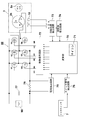
- FIG. 2 is a schematic block diagram of the impact tool 1 of this embodiment.
- a battery 90 composed of a secondary battery is used as a power source.
- the arithmetic unit 70 includes a microcomputer 71 and drives an inverter circuit 80 composed of a plurality of semiconductor switching elements Q1 to Q6.
- the motor 3 is a so-called inner rotor type, and has three position detection elements arranged at intervals of 60 ° so as to face the rotor 3a configured by embedding a magnet (permanent magnet) including a pair of N poles and S poles. 13 is provided.
- the stator 3b includes star-connected three-phase windings U, V, W.
- the calculation unit 70 is an example of the "control unit" of the present invention.
- the inverter circuit 80 is composed of six switching elements Q1 to Q6 such as FETs connected in a three-phase bridge format.
- a capacitor 77 for suppressing fluctuation at the time of rising current is provided in parallel with the battery 90 between the inverter circuit 80 and the battery 90.
- the microcomputer 71 drives and controls the switching elements Q1 to Q6 via the control signal output circuit 72.
- Each gate of the six switching elements Q1 to Q6 bridged is connected to the control signal output circuit 72, and each drain or source of the six switching elements Q1 to Q6 is a star-connected stator winding. Connected to U, V, W.
- the six switching elements Q1 to Q6 perform a switching operation by the switching element drive signal (drive signal of H4, H5, H6, etc.) input from the control signal output circuit 72, and are applied to the inverter circuit 80.
- the DC voltage of the battery 90 is set as three-phase (U-phase, V-phase and W-phase) voltages Vu, Vv and Vw, and power is supplied to the stator windings U, V and W.
- the switching element drive signals (3-phase signals) that drive each gate of the 6 switching elements Q1 to Q6, the three switching elements Q4, Q5, and Q6 on the negative power supply side are pulse width modulated signals (PWM signals) H4. , H5, H6, and the power to the motor 3 by changing the pulse width (duty ratio) of the PWM signal based on the detection signal of the operation amount (stroke) of the trigger lever 7a of the trigger switch 7 by the microcomputer 71.
- the supply amount is adjusted to control the start / stop and rotation speed of the motor 3.
- the calculation unit 70 includes a microcomputer 71, and is connected to a current detection circuit 75, a switch operation detection circuit 76, a rotation position detection circuit 73, and a rotation speed detection circuit 74.
- the microcomputer 71 that forms the core of the arithmetic unit 70 is a CPU for outputting a drive signal based on a processing program and data, and a ROM for storing programs and control data corresponding to the flowchart described later. It is configured with a built-in RAM for temporarily storing data, a timer, and the like.
- the current detection circuit 75 detects the current flowing through the motor 3 by measuring the voltage across the shunt resistor 78, and the detection output is input to the microcomputer 71.
- the switch operation detection circuit 76 detects whether or not the trigger lever 7a is pulled, and if it is pulled even a little, an on signal is output to the microcomputer 71.
- the rotation position detection circuit 73 is a circuit for detecting the relational positions between the armature windings U, V, and W of the rotor 3a and the stator 3b based on the output signals of the three position detection elements 13.
- the rotation speed detection circuit 74 is a circuit that detects the rotation speed of the motor based on the number of detection signals from the rotation position detection circuit 73 counted within a unit time.
- the control signal output circuit 72 supplies PWM signals H1 to H6 to the switching elements Q1 to Q6 based on the output from the microcomputer 71.
- the power supplied to each armature winding U, V, W is adjusted by controlling the pulse width of the PWM signal.
- FIG. 3 is a diagram for explaining a transition of a work situation in which a plurality of members are tightened by the impact tool 1 of the present embodiment.
- the bolt 61 is formed by a head portion 61a of a regular hexagonal column having an outer diameter and a shaft portion 61b extending downward from the bottom surface of the head portion 61a, and male threads 61c are formed in the entire axial direction of the shaft portion 61b. ..
- the nut 62 has a through hole formed in the center of a regular hexagonal prism, and a female screw is formed on the inner surface of the through hole.
- the steel plate portions 65 and 66 of the two steel frames are examples of the "plurality of members" of the present invention, and the bolt 61 and the nut 62 are examples of the "fastener” of the present invention.
- the objects to be tightened by the bolt 61 and the nut 62 are the steel plate portions 65 and 66 which are part of separate steel frames and have through holes for penetrating the bolt 61.
- iron plate portions 65 and 66 having different thicknesses are tightened, a washer 63 is interposed between the head portion 61a of the bolt 61 and the iron plate portion 65, and a washer 64 is interposed between the nut 62 and the iron plate portion 66. Is intervened.
- an example of rotating the lower nut 62 side using the impact tool 1 will be described.
- this state is referred to as a "close contact state", and is a state detected by the method described in this embodiment.
- a state in which a plurality of members such as the iron plate portions 65 and 66 are tightened by fasteners such as bolts 61 and nuts 62 and are in close contact with each other is an example of the "close contact state" of the present invention.
- the microcomputer 71 included in the calculation unit 70 of the impact tool 1 executes the tightening of the specified torque amount from the state where the “close contact state” is reached. For example, in the assembling work of a steel frame for a private house, tightening is performed with a specified torque of about 100 Nm. A predetermined tightening F (see FIG. 4 to be described later) is performed until the specified tightening completion state shown in FIG. 3 (E) is performed via the state. How to set the tightening F is preset by the manufacturer of the tightening tool.
- FIG. 4 is a graph showing the relationship between the passage of time, the peak value 82 of the current of the motor 3 and the moving average 83 of the peak value 82 of the current when the nut 62 is tightened to the tightening target shown in FIG. be.
- the microcomputer 71 of the arithmetic unit 70 uses the output of the current detection circuit 75 to set the current value in real time. To monitor.
- the waveform to be monitored is 82.
- the output of the current detection circuit 75 (current waveform 81 described later in FIG. 5) is not plotted as it is, but the peak value 82 of the detected current is plotted and the plot points are connected by a straight line. ..
- a method of detecting the peak value 82 of the current will be described with reference to FIG.
- FIG. 5 is an enlarged view of a part of the current waveform 81 of the motor 3, and is a waveform diagram of a signal input to the microcomputer 71 from the current detection circuit 75 shown in FIG.
- the motor 3 is driven by using the inverter circuit 80 as described with reference to FIG. 2 using the inner rotor type brushless DC motor as the drive source.
- PWM PulseWidthModulation
- the PWM control controls the motor 3 by changing the duty cycle (ratio of H and L of the pulse width) of the pulse width according to the magnitude of the input signal (DC voltage) with a constant cycle. be.
- the current waveform 81 moves up and down so as to undulate with a period of about 0.02 seconds.
- the repetitive striking operation by the impact mechanism 25 is configured to be repeated in a cycle of about 0.02 seconds.
- the fluctuation of the current waveform 81 with a period of about 0.02 seconds shown in FIG. 5 is caused by the repeated striking operation with the same period of about 0.02 seconds.
- the current values shown by the arrows 81a, 81b, and 81c are the peak values of the current of the current waveform 81 that fluctuates due to the repeated striking operation. Therefore, the microcomputer 71 takes out the current values shown by the arrows 81a, 81b, and 81c as the peak value 82 of the current caused by the repeated striking operation, and uses them for the determination process of the close contact state.
- the waveform of the peak value 82 of the current in FIG. 4 is obtained by plotting a large number of current values indicated by arrows 81a, 81b, and 81c in FIG. 5 and connecting the plots with a line.
- the spire-shaped current values other than the arrows 81a, 81b, and 81c are not generated due to the repeated striking operation and are not used as values for determining the close contact state.
- the integrated value of the current in the vicinity of the peak value of the current may be used, or the average value of the peak values of a plurality of adjacent currents may be used. Conceivable.
- the magnitudes of the current peaks 81a, 81b, 81c, and 82 generated by the repeated impact operation of the impact mechanism 25 are an example of the “current peak value” of the present invention.
- the peak value 82 of the current gradually increases as shown by the arrows (A) to (E) as the tightening by the impact tool 1 is performed.
- the moving average 83 of the peak value 82 of the current is obtained by calculating and plotting the moving average of the peak values 82 of the latest plurality of currents.
- the number of samples for calculating the moving average may be, for example, about 3 to 5.
- the inclination value of the moving average 83 which has risen almost linearly until then, becomes large.
- the state of the arrow (A) is a state in which the rotation of the nut 62 to be tightened after the "seating state” is hindered, and the current value flowing through the motor 3 suddenly rises.
- the iron plate portions 65 and 66 shown in FIG. 3 move in the approaching direction due to the tightening of the bolt 61 and the nut 62.
- the moving average 83 indicated by the arrow (C) and the arrow (4) is the moving average of the peak values 82 of the three most recent currents (1) to (3).
- the present invention as the determination of the adhesion state of the clamping object, using a threshold current I S of the peak value of the current flowing in the motor (the peak value of the current 82), the peak value of the current itself, or, the peak current If the function value (moving average 83) exceeds the threshold value I S, it is determined that a plurality of clamping object member (iron plate 65, 66) becomes close contact.
- the first control mode is changed to the second.
- the necessary conditions for determining that the first switching condition is satisfied are that the peak value of the current tends to increase and the rate of change of the peak value of the current. It is conceivable that the increase is a necessary condition.
- FIG. 6 is a graph showing the change amount 84 of the moving average 83 of the peak value 82 of the current shown in FIG. 4, and the calculated change amount of the moving average 83, that is, the calculated moving average 83 (see FIG. 4). It is a plot of the difference between the moving average and the moving average 83 calculated immediately before that. The horizontal axis is the tightening time, and the vertical axis is the amount of change in the moving average value of the peak value 82 of the current.
- +0.2 means that the moving average has increased by 0.2 (A) from the moving average 83 calculated immediately before
- -0.2 means that the moving average has increased from the moving average 83 calculated immediately before. It shows that it decreased by 0.2 (A).
- the increase determination threshold value I 1 is set to 0.2 A, and the time point of the arrow (4) in which the change amount 84 increases the increase determination threshold value I 1 three times in a row is determined to be “close contact state”. .. It should be noted that not only the point at which the amount of change in the moving average 83 appears significantly before and after the close contact state is determined as the "close contact state", but also the "close contact” state may be determined by monitoring the inclination of the moving average 83.
- the moment of inertia of the rotating system by the motor 3, the spindle 26, and the hammer 30 is configured to be lower than before.
- the moment of inertia of the motor 3 is affected by the square of the reduction gear ratio of the reduction mechanism 20. That is, when the gear ratio is lowered, the moment of inertia is lowered.
- the torque of the motor 3 and the magnitude of the moment of inertia of the rotating system basically affect the moment of inertia. If it is large, the decrease in the rotation speed is small, so that the change in the current value of the motor 3 does not become large.
- the gear ratio of the reduction mechanism 20 is set to be lower than before.
- the deceleration is performed at a gear ratio of 8.286, but in this embodiment, it is set to about 5.0 or less.
- an inner rotor type brushless DC motor as the motor 3 instead of a brushed DC motor. Since the inner rotor type brushless DC motor has a small moment of inertia of the rotor, the current value is likely to change when the object to be tightened is in close contact, and the detection accuracy of the close contact state using the peak current as in this embodiment is high. ..
- the control procedure shown in FIG. 7 can be realized by software by executing a computer program in the arithmetic unit 70 having the microcomputer (microprocessor) 71.
- the microcomputer 71 detects whether or not the trigger lever 7a is pulled by the operator and the trigger switch 7 is turned on, and if it is pulled, the process proceeds to step 102 (step 101). If the trigger switch 7 is not turned on, the microcomputer 71 waits until it is turned on.
- step 101 when the trigger lever 7a is pulled even a little and the trigger switch 7 is turned on, the microcomputer 71 rotates and drives the motor 3 according to the pulling amount of the trigger lever 7a.
- This rotary drive is referred to as a "first control mode" in order to distinguish it from the rotary drive of step 107 described later.
- the calculation unit 70 continuously rotates the motor 3 by, for example, constant speed control, while the trigger switch 7 is ON, until a predetermined condition is satisfied. While the motor 3 is being driven in the first control mode, the motor 3 detects peak currents (1), (2), and (3) in one cycle of PWM control by the method described with reference to FIG.
- step 106 if the moving average 83 is equal to or less than the threshold current I S returns to step 102, if it exceeds the threshold current I S, the microcomputer 71 of the driving mode of the motor 3 is switched to "second control mode" motor 3 is driven (step 107).
- microcomputer 71 is the moving average 83 shows an example of determining a "first switching condition is satisfied" that exceeds the threshold current I S shown in FIG. 4, the first switching condition is satisfied
- Other conditions for determining that the current was achieved were (1) the peak value of the current was equal to or higher than the predetermined value, (2) the moving average value of the peak value of the current was greater than or equal to the predetermined value, and (3).
- the slope of the moving average value of the peak value of the current exceeds a predetermined value, (4) any one of (1) to (3) occurs multiple times, and (5) from (1) above. It may be configured so that any one of (3) occurs consecutively multiple times as a necessary condition.
- the control of continuously rotating the motor 3 until a predetermined condition is satisfied while the trigger switch 7 is ON is an example of the "first control mode" of the present invention.
- the "second control mode" in step 107 is the tightening control from reaching the close contact state of FIG. 3 (C) to (E), in order to accurately tighten the tightening target with a specified torque value.
- Rotation control Various settings can be made as to how the rotation control from FIG. 3C to FIG. 3E is performed.
- a machine learning device (not shown) configured to generate a determination algorithm for determining the tightening state of the fastener to be fastened by the impact tool 1 is used to learn the adhesion condition, and the algorithm generated by the machine learning device is used as a microcomputer. It is good to execute at 71.
- the machine learning device (not shown) has an input unit and an input unit configured to input tightening data in which physical information related to the load applied to the motor 3 of the impact tool 1 and the tightening state of the fastener are associated with each other. It has a generator configured to perform machine learning by a genetic algorithm and generate the determination algorithm for determining the tightening state based on the tightening data input in.
- the control from the satisfaction of a predetermined condition to the completion of tightening is an example of the "second control mode" of the present invention.
- the input values for inputting the tightening data to the machine learning device are the current of the motor 3, the rotation speed, and the voltage of the battery 90, and by performing machine learning using a genetic algorithm, the optimum "first" for each tightening target.
- Detailed control in “2 control mode” can be derived.
- the detailed control in this "second control mode” is performed by the manufacturer who develops the impact tool 1 by using a machine learning device at the time of development, and software and parameters for deriving the results are preliminarily sent to the calculation unit 70 of the impact tool 1. You can store it.
- step 107 the motor 3 is driven until the second switching condition different from the first switching condition is satisfied, and when the second switching condition is satisfied, the rotation of the motor 3 is stopped. (Step 109).
- the rotation of the motor 3 after close contact is controlled, but the microcomputer 71 satisfies the second switching condition.
- the repeated striking operation was executed a predetermined number of times after the first switching condition was satisfied, or the repetitive striking operation was executed for a predetermined time after the first switching condition was satisfied.
- One of the requirements is required.
- step 109 it is not limited to (a) stopping the rotation of the motor 3, but (b) reducing the rotation speed of the motor 3 or (c) the first switching condition. Will execute the above (a) or (b) when a different second switching condition is satisfied, or (d) notify the operator of the completion of tightening by a notification unit that emits a sound or light. It may be configured.
Landscapes
- Engineering & Computer Science (AREA)
- Mechanical Engineering (AREA)
- Portable Power Tools In General (AREA)
- Details Of Spanners, Wrenches, And Screw Drivers And Accessories (AREA)
Abstract
ボルトやナットなどの締結具を用いて複数の部材の締め付け作業を行う際に、部材間に隙間がある場合でも精度良く締め付けができる締め付け工具を提供する。モータに接続される伝達機構と、伝達機構に接続された先端工具を有し、互いに離れた複数の部材を締結具により締め付ける工具において、モータの回転を制御する制御部は、第1制御モード(ステップ102)か、又は第1制御モードとは異なる第2制御モード(ステップ107)で制御するよう構成する。制御部は伝達機構から先端工具に伝達されるトルクが繰り返し断続する打撃動作を実行している際に、締結具によって複数の部材が離間した状態から互いに密着する状態に移行したと判断した場合(ステップ105、106)、モータの制御を第1の制御モードから第2の制御モードに切り替える。この密着状態はピーク電流値の移動平均を用いて判定する。
Description
本発明は、ネジなどの締結具を締め付けるための締め付け工具に関するものである。
締め付け工具は、モータと、モータに接続された伝達機構と、伝達機構に接続された先端工具を備えている。作業者は、先端工具をネジなどの締結具に接続し、モータの回転力を伝達機構を介して先端工具に伝達させることにより、締結具を締め付ける締め付け作業を行う。
締め付け工具の伝達機構としては、モータの回転を減速する減速機構と、モータの連続的な回転を断続的なトルクに変換するインパクト機構、を用いる構成が知られている。このような締め付け工具において、モータの回転を制御する制御部を備え、締め付け作業中に所定の条件が満たされた場合に、モータの回転状態を変化させるものが知られている。例えば、特許文献1には、ボルトで硬い部材を締め付ける作業においてインパクト機構が破損するのを防止のため、インパクト機構により反復した打撃が行われているときに、モータに流れる電流が所定値を超えると、モータに流れる電流を低下させるインパクト工具が開示されている。特許文献2には、ボルトで硬い部材を締め付ける作業においてインパクト機構が破損するのを防止のため、インパクト機構により反復した打撃が行われているときに、モータに流れる電流が所定値を超えると、インパクト機構が打撃力を発生する前後の第1の所定期間に亘ってモータに流れる電流を低下させるインパクト工具が開示されている。
特許文献3には、小さなネジを締め付ける作業において正確な締め付けを可能とするため、インパクト機構による最初の打撃が行われる前にモータに印加するデューティ比を低くし、低デューティ比にて打撃を行うインパクト工具が開示されている。特許文献4には、ネジやボルトを締め付ける作業において高速かつ正確な締め付けを可能とするため、インパクト機構による複数回の打撃が継続し、モータに流れる電流が所定値を超えると、ネジ又はボルトが部材に着座したと判断して、モータに加わるデューティ比を低下させるインパクト工具が開示されている。特許文献5には、ネジで石膏ボードを締め付け作業において正確な締め付けを可能とするため、インパクト機構による打撃が行われない状態でネジが部材に着座すると、モータの回転を停止させるインパクト工具が開示されている。
特許文献4のインパクト工具では、インパクト機構による複数回の打撃が継続し、モータに流れる電流が所定値を超えると、ネジ又はボルトが部材に着座したと判断して、その後のモータの回転制御を行う。しかしながら、ボルトで複数の部材を互いに締結する締め付け作業において、ボルトを締め付ける前には一方の部材と他方の部材の間に隙間がある場合がある。このような場合、ボルトを正確に締め付けるためには、ボルトを締め付ける過程で、まずボルトを複数の部材のうち一方の部材に着座させ、次に複数の部材のうち一方又は他方の部材を締め付け力によって変形させて隙間を小さくし、最後に複数の部材を互いに密着させて、密着させた状態から必要とされる締め付けを確実に行うべきである。このような作業において特許文献4に開示されたインパクト工具を用いた場合、ボルトが一方の部材に着座した時点で、モータに流れる電流が所定値を超えてしまい、モータに加わるデューティ比が低下することになる。その結果、複数の部材が互いに密着する前に締め付けトルクが低下してしまい、ボルトが十分に締め付けられなくなる虞がある。
本発明は上記背景に鑑みてなされたもので、その目的は、ボルトやナットなどの締結具を用いて複数の部材の締め付け作業を行う際に、締め付け対象となる部材間に隙間があるような場合であっても精度良く締め付けることを可能とした締め付け工具を提供することにある。本発明の他の目的は、ボルトやナットなどの締結具によって複数の部材の締め付け作業を行う際に、測定された電流値を用いて、着座状態による電流値増加と、締め付け途中の部材間密着状態による電流値増加を区別して、確実な締め付け作業を行うことができるようにした締め付け工具を提供することにある。
本願において開示される発明のうち代表的な特徴を説明すれば次のとおりである。本発明の一つの特徴によれば、モータと、モータに接続される伝達機構と、伝達機構に接続された先端工具であって、互いに離れた複数の部材を締め付けるための締結具に接続できるよう構成された先端工具と、モータを第1制御モード又は第1制御モードとは異なる第2制御モードで制御するよう構成された制御部と、を有し、先端工具に負荷が加わった場合に、伝達機構から先端工具に回転打撃力を繰り返し伝達する反復打撃動作を実行するよう構成された締め付け工具において、制御部は、反復打撃動作が実行されている間に、複数の部材が締結具によって互いに密着する密着状態に移行したと判断した場合に、モータの制御を第1の制御モードから第2の制御モードに切り替えるよう構成した。本発明の他の特徴によれば、モータと、モータに接続される伝達機構と、伝達機構に接続された先端工具であって、互いに離れた複数の部材を締め付けるための締結具に接続できるよう構成された先端工具と、モータを制御する制御部と、を有し、先端工具に負荷が加わった場合に、伝達機構から前記先端工具に回転打撃力を繰り返し伝達する反復打撃動作を実行するよう構成された締め付け工具であって、制御部は、反復打撃動作が実行されている間に、複数の部材が締結具によって互いに密着して所定の条件が満たされると、モータの回転数を低下させる、又は、密着を報知するよう構成した。また、モータに流れる電流は反復打撃動作と略同じ周期で電流のピーク値が発生し、制御部は、反復打撃動作が実行されている間にモータに流れる電流のピーク値に関連する第1切替条件が満たされた場合に、複数の部材が密着状態に移行したと判断する。
本発明の他の特徴によれば、モータと、モータに接続される伝達機構と、伝達機構に接続された先端工具であって互いに離れた複数の部材を締め付けるための締結具に接続できるよう構成された先端工具と、締め付け工具の伝達機構として、モータの回転を減速する減速機構と、モータの連続的な回転を断続的なトルクに変換するインパクト機構を有する締め付け工具において、減速機構の減速比をモータ5回転あたりのインパクト機構の回転数が1回転以下となるように構成した。
本発明の他の特徴によれば、モータと、モータに接続される伝達機構と、伝達機構に接続された先端工具であって、互いに離れた複数の部材を締め付けるための締結具に接続できるよう構成された先端工具と、モータを第1制御モードか、又は第1制御モードとは異なる第2制御モードで制御するよう構成された制御部と、を有し、先端工具に負荷が加わった場合に、伝達機構から先端工具に回転打撃力を繰り返し伝達する反復打撃動作を実行するよう構成された締め付け工具において、伝達機構として、モータの回転を減速する減速機構と、モータの連続的な回転を断続的なトルクに変換するインパクト機構を有しており、減速機構の減速比を、モータ5回転あたりのインパクト機構の回転数が1回転以下となるよう構成し、制御部は、モータに流れる電流に関連する第1切替条件が満たされたと判断した場合に、モータの制御を第1の制御モードから第2の制御モードに切り替えるよう構成した。また、制御部は、反復打撃動作が実行されている間に、モータに流れる電流のピーク値に関連する第1切替条件が満たされた場合に、モータの制御を第1の制御モードから第2の制御モードに切り替える。さらに、制御部は、第1切替条件が満たされたと判断するために、少なくとも、電流のピーク値が、上昇する傾向にあること、及び、電流のピーク値の変化率が増加したことを必要条件とする。
本発明のさらに他の特徴によれば、モータに流れる電流値を測定する電流測定部を有する締め付け工具において、制御部は電流測定部による電流の測定値を監視し、第1切替条件が満たされたと判断するために、少なくとも、(1)電流のピーク値が所定値以上になったこと、(2)電流のピーク値の移動平均値が所定値以上になったこと、(3)電流のピーク値の移動平均値の傾きが所定値以上になったこと、(4)上記(1)から(3)のいずれかが複数回生じたこと、又は、(5)上記(1)から(3)のいずれかが複数回にわたり連続して生じたこと、のうちいずれかを必要条件とするようにした。また、制御部は、電流測定部による電流の測定値(モータを流れる電流)のピーク近傍における積分値を計算し、この積分値を電流のピーク値として上記の制御をする。
本発明のさらに他の特徴によれば、締め付け工具において制御部は、上記第2制御モードとして、(a)モータの回転を停止させるか、(b)モータの回転数を低下させるか、(c)第1切替条件とは異なる第2切替条件が満たされた場合に上記(a)又は(b)を実行するか、又は、(d)報知部によって報知するように構成した。また、制御部は、第2切替条件が満たされたと判断するため、少なくとも、(e)第1切替条件が満たされた後に反復打撃動作が所定回数だけ実行されたこと、又は、(f)第1切替条件が満たされた後に反復打撃動作が所定時間だけ実行されたこと、のうちいずれかを必要条件とするよう構成した。
本発明のさらに他の特徴によれば、締め付け工具と、締め付け工具によって締結される締結具と、を有する締め付けシステムであって、締め付け工具は、モータと、モータによって回転駆動される先端工具と、モータに加わる負荷に関連する物理的情報を検知する検知部と、モータを、第1制御モードか、又は第1制御モードとは異なる第2制御モードで制御するよう構成された制御部と、を有し、制御部は、検知部から入力される物理的情報にもとづいて、機械学習を用いて締結具の締め付け状態を判定して、判定結果を生成するよう構成された判定アルゴリズムを有し、制御部は、判定アルゴリズムによる判定結果に応じて、モータの制御を、第1制御モードから第2制御モードに移行するよう構成した締め付けシステムとした。
本発明のさらに他の特徴によれば、締め付け工具によって締結される締結具の締め付け状態を判定する判定アルゴリズムを生成するよう構成された機械学習装置であって、締め付け工具のモータに加わる負荷に関連する物理的情報と、締結具の締め付け状態と、を対応付けた締め付けデータを入力するよう構成された入力部と、入力部に入力された締め付けデータに基づいて、遺伝的アルゴリズムによる機械学習を実行し、締め付け状態を判定する判定アルゴリズムを生成するよう構成された生成部と、を有するようにした。
本発明によれば、ボルトやナットなどの締結具によって複数の部材間に隙間がある締め付け対象を締め付ける場合であっても、打撃動作中に先端工具から締結具に伝達される締め付けトルクの大きさを電流のピーク値から正確に推測できるので、締め付け対象の状態によらずに正確な締め付けトルクによる締め付けを行うことができる。
以下、本発明の実施例を図面に基づいて説明する。なお、以下の図において、締め付け工具の一例としてボルトやナットの締め付けを行うインパクト工具1を用いて説明し、同一の部分には同一の符号を付し、繰り返しの説明は省略する。また、本明細書においては、前後、上下の方向は図中に示す方向であるとして説明する。
図1は、本発明の実施例に係るインパクト工具1の外観を示す側面図である。インパクト工具1は、充電可能なパック式のバッテリ90(符号は図2参照)を電源とし、モータ3を駆動源として出力軸(アンビル40)に回転力と打撃力を与え、工具保持部41にてピン貫通孔42に保持されるソケットレンチ等の先端工具に回転打撃力を間欠的に伝達してねじ締めやボルト締め等の作業を行う。アンビル40の前端は工具保持部41が形成され、ここにソケット50等の先端工具を取り付け、ねじやボルト等の締結部材を相手材に締付けたり、緩めたりする。ソケット50は本発明の“先端工具”の一例である。工具保持部41は回転軸線A1と直交する断面形状が正方形であり、外周の4面の2つの中央には脱落防止用のピンを装着させるためのピン貫通孔42が形成される。
インパクト工具1のハウジング2は、モータ3や後述の伝達機構を収容するための略円筒状の筒状の胴体部2aと、胴体部2aの略中央付近から回転軸線A1と略直交方向に延在するものであって、作業者が片手で把持するためのハンドル部2bを有する略T字状の形状を成す。ハンドル部2bの端部のうち、胴体部2aと反対側に位置する下方側端部(反胴体部側端部)には、図示しないバッテリ取付部が形成され、図示しないバッテリが装着される。ハンドル部2b内の上部にはトリガレバー7aが前方側に突出するように配設され、トリガレバー7aの後方側にはモータ3の回転のオン又はオフを切り替えるトリガスイッチ7が設けられる。トリガスイッチ7の上方には、モータ3の回転方向を正方向又は逆方向に切り換えるための正逆切替レバー8が設けられる。
モータ3は筒状の胴体部2aの後方側に収容される。モータ3はブラシ(整流用刷子)の無いDC(直流)モータであり、4極6スロットのブラシレスDCモータである。モータ3は永久磁石を備えたロータ(回転子)3aと、3相巻線等の複数相の電機子巻線(固定子巻線)を備えたステータ(固定子)3bを含む。ロータ3aは、永久磁石によって形成される磁路を形成する。ステータ3bは、円環状の薄い鉄板の積層構造で製造され、内周側には6つのティース(図示せず)が形成され、各ティースにはエナメル線が巻かれてコイルが形成される。本実施例では、コイルをU、V、W相の3相を有するスター結線としている。モータ3は、ロータ3aの永久磁石の磁力を検出してロータ位置を検出する複数のホールICより構成された位置検出素子13の出力を用いて、バッテリ等から供給される直流電圧を複数の半導体スイッチング素子14(によってスイッチングされることにより動作する。
モータ3の回転軸4は筒状の胴体部2aの回転軸線A1と同心に配置され、前側及び後側において2つの軸受16a、16bによってハウジング2に軸支される。ステータ3bの後方側には、3つの位置検出素子13や6つの半導体スイッチング素子14等を搭載するための略円環状のインバータ回路基板12が配置される。インバータ回路基板12はモータ3の外径とほぼ同径の略円環状の両面基板である。半導体スイッチング素子14は6つ設けられてインバータ回路80(図2で後述)を形成し、各相の固定子巻線への通電を切換える。半導体スイッチング素子14として図2でQ1~Q6にて示すFET(電界効果トランジスタ)やIGBT(絶縁ゲート・バイポーラ・トランジスタ)等が用いられる。インバータ回路はマイクロコンピュータ(図2で後述するマイコン71)により制御され、位置検出素子13によるロータ3aの位置検出結果に基づいて各相の電機子巻線の通電タイミングを設定するので、高度な回転制御が容易となる。
ロータ3aと軸受16aの間には、冷却ファン15が回転軸4と同軸に取り付けられる。冷却ファン15は、例えばプラスチックのモールドにより一体成形されるものであり、胴体部2aの後端側付近に形成される図示しない空気取入口から空気を吸引する。吸引された空気はインバータ回路基板12の搭載素子を冷却した後、ロータ3aとステータ3bの間を通過するように、及び、ステータ3bの外周側を前方側に流れることによりモータ3を冷却する。冷却ファン15に到達した空気は、冷却ファン15の回転により径方向外側に排出され、冷却ファン15の左右側面に形成された空気排出用のスリット(図示せず)から外部に排出される。
ハウジング2の前方側にはカップ状に形成されたハンマケース5が設けられる。ハンマケース5は、内部に減速機構20とインパクト機構25を収容するものであって、ハウジング2の胴体部2aの前方側に設けられる。ハンマケース5は金属の一体品にて製造され、カップ状の底部にあたる前方部分にはアンビル40を貫通させるための貫通穴5aが形成される。ハンマケース5の外側であって、アンビル40の先端部分に図示しない先端工具を装着又は取り外しできるための工具保持部41となる。ハンマケース5の前方端付近の下側には、LEDを用いた照明装置9が設けられる。
ハウジング2の胴体部2aから略直角に一体に延びるハンドル部2b内の上部にはトリガレバー7aが前方側に突出するように配設され、使用者はハンドル部2bを片手で把持し、人差し指等によってトリガレバー7aを後方に引くことによって、トリガ押込量(操作量)を調整し、モータ3の回転数を制御できる。モータ3の回転方向は、正逆切替レバー8を操作することによって締め付け方向又は緩め方向に切り替えることができる。
ハウジング2の胴体部2aは、ハンドル部2bと共に合成樹脂材料の一体成形により製造され、モータ3の回転軸4を通る鉛直面で左右に2分割可能に形成される。組立の際にはハウジング2の左側部材と右側部材を準備し、予め、図1の断面図で示すような一方のハウジング2(例えば左側のハウジング)に、減速機構20、インパクト機構25を組み込んだハンマケース5とモータ3等の組込みを行い、しかる後、他方のハウジング2(例えば右側のハウジング)を重ねて、複数のネジで締め付ける。
インパクト機構25は遊星歯車による減速機構20の出力側に設けられるもので、スピンドル26とハンマ30を備え、後端が軸受18b、前端がメタルによる軸受18aにより回転可能に保持される。減速機構20は、モータ3の回転軸4の先端に固定されるサンギヤ21と、サンギヤ21の外周側に距離を隔てて取り囲むように設けたリングギヤ23と、サンギヤ21とリングギヤ23の間の空間に配置され、これら双方のギヤに噛み合わされる複数のプラネタリーギヤ22を含んで構成される。リングギヤ23は、アウターギヤとも呼ばれるもので、リング状部材の内周面にギヤが形成される。リングギヤ23はインナカバー19を介してハウジング2によってその外周面が保持される。インナカバー19の主な役割は、2つ設けられる軸受18bと軸受16aを保持すると共に、モータ3の回転軸4とスピンドル26の回転中心を同軸上に芯だしするためである。インナカバー19によって保持される軸受18bはモータ3の回転軸4を軸支するためであって、例えばボールベアリングが用いられる。インナカバー19によって保持される軸受18bは、スピンドル26の後端を軸支するためであって、例えばボールベアリングが用いられる。
複数(ここでは3つ)のプラネタリーギヤ22は、スピンドル26の後端部に形成された遊星キャリア部に軸支され、プラネタリーギヤ22が遊星キャリア部に軸支されるシャフトの回りを自転しながらサンギヤ21の回りを公転する。リングギヤ23自体は回転しない。モータ3の回転軸4が回転すると、それに同期してサンギヤ21も回転する。サンギヤ21の回転力は、所定の比率(ここでは5:1)で減速されて遊星キャリア部26bに伝達されるので、スピンドル26が回転する。
減速機構20とインパクト機構25が、モータ3によって先端工具を駆動するための伝達機構を構成する。トリガレバー7aが引かれてモータ3が起動されると、正逆切替レバー8で設定された方向にモータ3が回転を始め、その回転力は減速機構20によって減速されてスピンドル26に伝達され、スピンドル26が所定の速度で回転する。ここで、スピンドル26とハンマ30とはカム機構によって連結され、このカム機構は、スピンドル26の外周面に形成されたV字状のスピンドルカム溝26aと、ハンマ30の内周面に形成されたハンマカム溝39と、これらのカム溝26a、29に係合する2つのスチールボール27によって構成される。ハンマ30は、ハンマスプリング28によって常に前方に付勢される。ハンマ30とアンビル40の対向する回転平面上の3箇所には回転軸線A1方向に凸状に突出する打撃爪36と、打撃爪36によって打撃される被打撃爪46が回転対称に形成される。
スピンドル26が回転駆動されると、その回転はカム機構を介してハンマ30に伝達され、ハンマ30が半回転しないうちにハンマ30の打撃爪36がアンビル40の被打撃爪46に係合してアンビル40を回転させる。回転時のハンマ30とアンビル40の係合反力によってスピンドル26とハンマ30との間に相対回転が生ずると、ハンマ30はカム機構のスピンドルカム溝26aに沿ってハンマスプリング28を圧縮しながらモータ3側へと後退を始める。そして、ハンマ30の後退動によってハンマ30の打撃爪36がアンビル40の被打撃爪46を乗り越えて両者の係合が解除されると、ハンマ30は、スピンドル26の回転力に加え、ハンマスプリング28に蓄積されていた弾性エネルギーとカム機構の作用によって回転方向及び前方に急速に加速されつつ、ハンマスプリング28の付勢力によって前方へ移動し、ハンマ30の打撃爪36がアンビル40の被打撃爪46に再び係合して一体に回転し始める。ハンマ30およびアンビル40が相対的に1回転すると打撃数(同時打撃)は3回(低速打撃)又は1.5回(高速打撃)となる。このように強力な回転打撃力がアンビル40に加えられるため、アンビル40の先端に固定される図示しない先端工具に回転打撃力が伝達される。
以後、同様の動作が繰り返されて先端工具に回転打撃力が間欠的に繰り返し伝達され、例えば、ボルト61やナット62等の締結具が締め付けられる。減速機構20とインパクト機構25によって構成される伝達機構は、本発明の“伝達機構”の一例である。伝達機構によって先端工具に伝達される回転方向の打撃力は、本発明の“回転打撃力”の一例である。伝達機構によって回転打撃力を先端工具に繰り返し伝達する動作は、本発明の“反復打撃動作”の一例である。
図2は本実施例のインパクト工具1の概略ブロック図である。本実施例では電源として二次電池で構成されたバッテリ90を用いる。ブラシレスDCモータを制御するために演算部70はマイコン71を含み、複数の半導体スイッチング素子Q1~Q6により構成されるインバータ回路80を駆動する。モータ3は、いわゆるインナーロータ型で、一対のN極およびS極を含むマグネット(永久磁石)を埋め込んで構成されたロータ3aに対向するように、60°毎に配置された3つの位置検出素子13が設けられる。ステータ3bにはスター結線された3相巻線U、V、Wが含まれる。演算部70は、本発明の“制御部”の一例である。
インバータ回路80は、3相ブリッジ形式に接続されたFETなどの6個のスイッチング素子Q1~Q6により構成される。インバータ回路80とバッテリ90の間には、電流の立ち上がり時の変動を抑えるためのコンデンサ77が、バッテリ90と並列に設けられる。マイコン71は、制御信号出力回路72を介してスイッチング素子Q1~Q6の駆動制御をする。ブリッジ接続された6個のスイッチング素子Q1~Q6の各ゲートは、制御信号出力回路72に接続され、6個のスイッチング素子Q1~Q6の各ドレインまたは各ソースは、スター結線された固定子巻線U、V、Wに接続される。これによって、6個のスイッチング素子Q1~Q6は、制御信号出力回路72から入力されたスイッチング素子駆動信号(H4、H5、H6等の駆動信号)によってスイッチング動作を行い、インバータ回路80に印加されるバッテリ90の直流電圧を3相(U相、V相及びW相)電圧Vu、Vv、Vwとして固定子巻線U、V、Wに電力を供給する。
6個のスイッチング素子Q1~Q6の各ゲートを駆動するスイッチング素子駆動信号(3相信号)のうち、3個の負電源側のスイッチング素子Q4、Q5、Q6をパルス幅変調信号(PWM信号)H4、H5、H6として供給し、マイコン71によって、トリガスイッチ7のトリガレバー7aの操作量(ストローク)の検出信号に基づいてPWM信号のパルス幅(デューティ比)を変化させることによってモータ3への電力供給量を調整し、モータ3の起動/停止と回転速度を制御する。
演算部70は、マイコン71を含んで構成され、電流検出回路75、スイッチ操作検出回路76、回転位置検出回路73、回転数検出回路74が接続される。演算部70の中核をなすマイコン71は、図示されていないが、処理プログラムとデータに基づいて駆動信号を出力するためのCPUと、後述するフローチャートに相当するプログラムや制御データを記憶するためのROMと、データを一時記憶するためのRAMと、タイマ等を内蔵して構成される。電流検出回路75はシャント抵抗78の両端電圧を測定することによりモータ3に流れる電流を検出するものであって、検出出力はマイコン71に入力される。尚、本実施例ではシャント抵抗78をバッテリ90とインバータ回路80の間に設けて半導体スイッチング素子Q1~Q6に流れる電流値(=モータ3の電流)を検出する方式であるが、シャント抵抗78をインバータ回路80とモータ3の間に設けてモータ3に流れる電流値を直接測定するようにしても良い。
スイッチ操作検出回路76はトリガレバー7aが引かれているかどうかを検出するもので、少しでも引かれていればオン信号をマイコン71に出力する。回転位置検出回路73は、3つの位置検出素子13の出力信号に基づいてロータ3aとステータ3bの電機子巻線U、V、Wとの関係位置を検出するための回路である。回転数検出回路74は、単位時間内にカウントされる回転位置検出回路73からの検出信号の数に基づいてモータの回転数を検出する回路である。制御信号出力回路72は、マイコン71からの出力に基づいてスイッチング素子Q1~Q6にPWM信号H1~H6を供給する。PWM信号のパルス幅の制御によって各電機子巻線U、V、Wへ供給する電力を調整する。
図3は本実施例のインパクト工具1によって複数の部材を締め付ける作業状況の推移を説明するための図である。ここではインパクト工具1を用いて、ボルト61とナット62により2つの鉄骨の鉄板部65、66を締め付ける作業の手順を示している。ボルト61は、外径が正六角柱の頭部61aと、頭部61aの底面から下方に延在する軸部61bにより形成され、軸部61bの軸線方向全体に雄ねじ61cが形成されたものである。ナット62は、正六角柱の中央に貫通孔が形成されたものであり、貫通孔の内面に雌ねじが形成される。2つの鉄骨の鉄板部65、66は本発明の“複数の部材”の一例であり、ボルト61とナット62は本発明の“締結具”の一例である。
ボルト61とナット62によって締め付ける対象物は、別々鉄骨の一部であってボルト61を貫通させるための貫通孔を有する鉄板部65、66である。ここでは厚さの異なる鉄の鉄板部65、66を締め付けるもので、ボルト61の頭部61aと鉄板部65の間にはワッシャ63が介在され、ナット62と鉄板部66の間にはワッシャ64が介在される。ここでは、インパクト工具1を用いて下側のナット62側を回転させる例で説明する。
図3(A)の状態は、ボルト61の軸部61bを鉄板部65、66の貫通孔の上から下方向に貫通させて、その先端にナット62を螺合させたものである。ボルト61の頭部61aが回転しないように保持した状態で、インパクト工具1によりナット62を締め付けると、ナット62の上部がワッシャ64に当接した状態となる。この状態は、締め付け対象(ナット62)が、ワッシャ64を介して締め付け対象(鉄板部65)に達した状態であり、この状態を“着座状態”と呼ぶ。この際の鉄板部65、66は密着しておらず、例えば、その間隔はC1である。
図3(A)の状態からさらにナット62を締め付けると、ナット62が上方に移動し、ワッシャ64と鉄板部66を白矢印(図3(B))に示す方向、即ち上方に移動させる。図3(B)の状態は、この締め付けの途中であり。鉄板部65、66が接近してその間隔がC1からC2に減少している(C1>C2)。図3(B)の状態からさらにナット62を締め付けると、ワッシャ64と鉄板部66が上方にさらに移動して、図3(C)に示すように鉄板部65、66が接する状態となる。この状態は、ボルト61の頭部61a、ワッシャ63、鉄板部65、66、ワッシャ64、ナット62が接した状況になり、実質的な隙間Cが無くなった状態(C=0)である。本明細書ではこの状態を“密着状態”と呼び、本実施例で説明する方法にて検出される状態である。鉄板部65、66のような複数の部材が、ボルト61及びナット62のような締結具によって締め付けられ互いに隙間なく接した状態は、本発明の“密着状態”の一例である。
ここで、インパクト工具1の演算部70に含まれるマイコン71は、“密着状態”に至った状態から規定されたトルク量の締め付けを実行する。例えば、個人住宅用の鉄骨の組み立て作業においては、規定トルク100N・m程度で締め付けを行うが、その締め付け量となるために、図3(C)の密着状態から、図3(D)で示す状態を経由して図3(E)で示す規定締め付け完了状態まで、所定の締め付けF(後述する図4を参照)を行う。締め付けFをどのように設定するかは、締め付け工具を製造するメーカによって予め設定されるものである。
図4は、図3に示した締め付け対象へのナット62を締め付ける際の、時間の経過とモータ3の電流のピーク値82、及び、電流のピーク値82の移動平均83の関係を示すグラフである。図3に示したようにインパクト工具1を用いて鉄骨等の締め付け対象に対するナット62の締め付けを行う作業中には、演算部70のマイコン71は電流検出回路75の出力を用いてリアルタイムに電流値を監視する。その監視対象の波形が82である。ここでは、電流検出回路75の出力(図5で後述する電流波形81)をそのままプロットしたものではなくて、検出された電流のピーク値82をプロットし、プロット点を直線で接続するようにした。ここで、図5を用いて電流のピーク値82の検出方法を説明する。
図5はモータ3の電流波形81の一部の拡大図であり、図2に示した電流検出回路75からマイコン71に入力される信号の波形図である。ここでは、一例としてナット62が着座することにより打撃が開始された状態(トリガレバー7aを引いてから時刻t=0.350秒付近)からt=0.390秒付近までの波形を示している。本実施例のインパクト工具1では、インナーロータ形のブラシレスDCモータを駆動源として、図2にて説明したようにインバータ回路80を用いてモータ3を駆動する。この際、モータ3への供給電圧をアナログ的に可変にするのではなく、PWM(PulseWidthModulation)制御を行う。PWM制御とは、周期は一定で、入力信号(直流電圧)の大きさに応じて、パルス幅のデューティ・サイクル(パルス幅のHとLの比)を変えて、モータ3を制御するものである。
図5のような電流波形81において、電流波形81が約0.02秒の周期で波打つように上下することが理解できる。本実施例のインパクト工具1において、インパクト機構25による反復打撃動作は、約0.02秒の周期で繰り返されるよう構成されている。図5にあらわれた周期約0.02秒の電流波形81の変動は、同じ周期約0.02秒の反復打撃動作に起因して生じたものである。図5の例では、矢印81a、81b、81cに示す電流値が、反復打撃動作に起因して変動する電流波形81の電流のピーク値となる。従って、マイコン71は矢印81a、81b、81cに示す電流値を、反復打撃動作に起因する電流のピーク値82として取り出して、密着状態の判定処理に利用する。
図4における電流のピーク値82の波形は、図5において矢印81a、81b、81cに示す電流値を多数プロットしてプロット間を線で接続したものである。尚、図5において矢印81a、81b、81c以外の尖塔状の電流値は、反復打撃動作に起因して発生したものではなく、密着状態を判定するための値としては利用されない。しかしながら、反復打撃動作に起因して発生した電流のピーク値の関数によって導き出される値を、密着状態を判定するための値として用いることは考えられる。例えば、そのような電流のピーク値の関数として、電流のピーク値の近傍における電流の積分値(例えば、1msの積分)を用いたり、隣接する複数の電流のピーク値の平均値を用いることが考えられる。インパクト機構25の反復打撃動作に起因して発生した電流のピーク81a、81b、81c、82の大きさは、本発明の“電流のピーク値”の一例である。
再び図4に戻る。電流のピーク値82は、インパクト工具1による締め付けを行うにつれて矢印(A)~(E)に示すように徐々に上昇する。電流のピーク値82の移動平均83は、直近の複数の電流のピーク値82の移動平均を計算してプロットしたものである。移動平均を計算するためのサンプル数は、例えば3~5程度で良い。電流のピーク値82の移動平均83を取得すると、モータ3に流れる電流の変化傾向を、正確に判定することが可能となる。例えば、着座した後であって、密接状態に至る途中(材料を引き込む)状態である矢印(A)においては、それまでほぼリニアに上昇していた移動平均83の傾き値が大きくなっている。この矢印(A)の状態が、“着座状態”の後の締め付けられるナット62の回転が阻害される状態であり、モータ3に流れる電流値が急上昇する。この状態から、さらにナット62を回転させると、ボルト61とナット62の締め付けによって図3で示した鉄板部65、66が接近する方向に移動する。この移動過程の移動平均83が矢印(B)の状態である。この後、移動平均83が所定の閾値、ここでは閾値電流IS=16.5Aを越えたら密着したと判定する。
矢印(C)及び矢印(4)で示す移動平均83は、直近の(1)~(3)の3つの電流のピーク値82の移動平均である。このようにして本発明では、締め付け対象の密着状態の判定として、モータに流れる電流のピーク値(電流のピーク値82)の閾値電流ISを用い、電流のピーク値そのもの、又は、電流のピーク値の関数(移動平均83)が閾値ISを越えた場合に、複数の締め付け対象部材(鉄板部65、66)が密着状態になったと判断する。電流のピーク値そのものが閾値Isを超えること、または電流のピーク値の関数が閾値Isを超えることは、いずれも、複数の部材が密着状態に移行したと判断して第1制御モードから第2制御モードに切り替えるための“第1切替条件”の一例である。このような第1切替条件が満たされたと判断するための必要条件として、上記のような例の他に、電流のピーク値が上昇する傾向にあること、及び、電流のピーク値の変化率が増加したことを必要条件とすることが考えられる。矢印(4)に示す位置にで、密着状態に移行したと判断されたら、マイコン71はモータ3の制御を変更して、規定の締め付け完了動作を行う。この密着状態に移行した時点を検出する方法を図6を用いて説明する。
図6は、図4に示す電流のピーク値82の移動平均83の変化量84を示すグラフであり、計算された移動平均83の変化量、即ち、計算された移動平均83(図4参照)とその直前に計算された移動平均83との差をプロットしたものである。横軸は締め付け時間であり、縦軸は電流のピーク値82の移動平均値の変化量である。ここで、+0.2とは直前に計算された移動平均83から移動平均が0.2(A)増えたことを示し、-0.2とは直前に計算された移動平均83から移動平均が0.2(A)減ったことを示している。本実施例では、増加判断閾値I1を0.2Aと設定して、変化量84が増加判断閾値I1を3回連続して増加した矢印(4)の時点を“密着状態”と判定する。尚、移動平均83の変化量が密着状態の前後において大きく現れる点を“密着状態”と判定するだけでなく、移動平均83の傾きを監視することによって“密着”状態を判定しても良い。
モータ3、スピンドル26、ハンマ30による回転系の慣性モーメントは、本実施例では従来よりも下げるように構成される。モータ3の慣性モーメントは、減速機構20の減速ギヤ比の二乗で影響する。つまり、ギヤ比を下げると慣性モーメントが下がる。インパクト機構25で打撃が行われて、ハンマ30が回転軸線A1方向に後退しているときに、基本的にはモータ3のトルクと回転系の慣性モーメントの大きさが影響するが、慣性モーメントが大きいと回転数の落ちこみが少ないので、モータ3の電流値の変化が大きくならない。つまり、ハンマ30の後退時に電流値が上がらないから、密着して締め付けしにくくなった状態(密着状態)のフィードバックが電流値の検出結果に影響しにくいことになる。一方、減速機構20のギヤ比が低いと相対的に回転系の慣性モーメントが下がるので、ハンマ30が後退したときに、ロータ3aの回転速度が大きく低下する。そうするとモータ3へ流れる電流値が高くなるので、着座や密着したという特徴事象を検出しやすくなる。その理由により、本実施例では減速機構20のギヤ比を従来よりも下げるようにした。従来は8.286というギヤ比で減速しているが、本実施例では5.0程度又はそれ以下にするようにした。このように減速比を小さくすると、遺伝的アルゴリズムを用いて機械学習させやすくなる。
モータ3としてブラシ付き直流モータでなく、インナーロータタイプのブラシレスDCモータを用いると好適である。インナーロータタイプのブラシレスDCモータは、ロータの慣性モーメントが小さいので、締め付け対象の密着状態時に電流値の変化が起きやすく、本実施例のようなピーク電流を用いた密着状態の検知精度が高くなる。
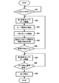
次に図7を用いてナット62の締め付け時の演算部70のマイコン71の制御手順を説明する。図7で示す制御手順は、マイコン(マイクロプロセッサ)71を有する演算部70においてコンピュータプログラムを実行することによりソフトウェア的に実現できる。まず、マイコン71は作業者によってトリガレバー7aが引かれてトリガスイッチ7がONになったか否かを検出し、引かれたらステップ102に進む(ステップ101)。トリガスイッチ7がONになっていない場合、マイコン71はONになるまで待機する。
ステップ101にて、マイコン71はトリガレバー7aが少しでも引かれてトリガスイッチ7がONになった場合は、トリガレバー7aの引き量に応じたモータ3の回転駆動を行う。この回転駆動は、後述するステップ107の回転駆動と区別するために“第1制御モード”と呼ぶ。“第1制御モード”において、演算部70は、トリガスイッチ7がONになっている間、所定の条件が満たされるまでモータ3を、例えば定速度制御によって連続して回転させる。第1制御モードでモータ3が駆動されている間に、モータ3は、図4で説明した方法によりPWM制御の一周期内におけるピーク電流(1)、(2)、(3)を検出し、それらの電流値をマイコン71の一時記憶メモリに格納する(ステップ103、104)。次に、マイコン71は、一時記憶メモリに格納された直近3つのピーク電圧値を用いて、ピーク電流の移動平均83を計算し(ステップ105)、移動平均83が図4で示した閾値電流ISを越えたか否かを判定する(ステップ106)。ステップ106で、移動平均83が閾値電流IS以下の場合はステップ102に戻り、閾値電流ISを越えた場合は、マイコン71はモータ3の駆動モードを“第2制御モード”に切り替えてモータ3の駆動を行う(ステップ107)。ここでマイコン71は、移動平均83が図4で示した閾値電流ISを越えたことを「第1切替条件が満たされた」と判断する例を示しているが、第1切替条件が満たされたと判断する他の条件としては、(1)前記電流のピーク値が所定値以上になったこと、(2)前記電流のピーク値の移動平均値が所定値以上になったこと、(3)前記電流のピーク値の移動平均値の傾きが所定値以上になったこと、(4)前記(1)から(3)のいずれかが複数回生じたこと、(5)前記(1)から(3)のいずれかが複数回にわたり連続して生じたこと、のうちいずれかを必要条件とするよう構成すれば良い。トリガスイッチ7がONになっている間、所定の条件が満たされるまでモータ3を連続して回転させる制御は、本発明の“第1制御モード”の一例である。
ステップ107における“第2制御モード”は、図3(C)の密着状態に達してから(E)に至るまでの締め付け制御であり、締め付け対象を規定のトルク値にて精度良く締め付けを行うための回転制御である。この図3(C)から(E)に至る回転制御をどのように行うかは、種々設定できる。例えば、インパクト工具1によって締結される締結具の締め付け状態を判定する判定アルゴリズムを生成するよう構成された図示しない機械学習装置を用いて密着条件を学習させ、機械学習装置によって生成されたアルゴリズムをマイコン71にて実行させると良い。図示しない機械学習装置は、インパクト工具1のモータ3に加わる負荷に関連する物理的情報と、締結具の締め付け状態と、を対応付けた締め付けデータを入力するよう構成された入力部と、入力部にて入力された締め付けデータに基づいて、遺伝的アルゴリズムによる機械学習を実行し、締め付け状態を判定する前記判定アルゴリズムを生成するよう構成された生成部を有する。所定の条件が満たされてから締め付けを完了するまでの制御は、本発明の“第2制御モード”の一例である。
締め付けデータを機械学習装置にインプットするための入力値として、モータ3の電流、回転数、バッテリ90の電圧とし、遺伝的アルゴリズムを用いた機械学習を行うことによって、締め付け対象ごとの最適な“第2制御モード”での詳細制御を導くことができる。この“第2制御モード”での詳細制御は、インパクト工具1を開発するメーカが、開発時に機械学習装置を用いて導いて、その結果を導くソフトウェアやパラメータをインパクト工具1の演算部70に予め格納しておけば良い。
ステップ107における“第2制御モード”では、第1切替条件とは異なる第2切替条件が満たされるまでモータ3の駆動を行い、第2切替条件が満たされた場合にモータ3の回転を停止させるようにした(ステップ109)。このようにして、“第1制御モード”とは違う“第2制御モード”による制御を行うことで、密着後のモータ3の回転制御を行うが、マイコン71は、第2切替条件が満たされたと判断するために、少なくとも、第1切替条件が満たされた後に反復打撃動作が所定回数だけ実行されたこと、又は、第1切替条件が満たされた後に反復打撃動作が所定時間だけ実行されたこと、のうちいずれかを必要条件とする。また、ステップ109で示したように、(a)モータ3の回転を停止させることだけに限られずに、(b)モータ3の回転数を低下させるか、又は、(c)第1切替条件とは異なる第2切替条件が満たされた場合に、前記(a)又は(b)を実行するか、又は、(d)音や光を発する報知部によって作業者に締め付けの完了を報知するように構成しても良い。
以上、本発明を実施例に基づいて説明したが、本発明は上述の実施例に限定されるものではなく、その趣旨を逸脱しない範囲内で種々の変更が可能である。
1…インパクト工具、2…ハウジング、2a…胴体部、2b…ハンドル部、3…モータ、3a…ロータ、3b…ステータ、4…回転軸、5…ハンマケース、5a…貫通穴、7…トリガスイッチ、7a…トリガレバー、8…正逆切替レバー、9…照明装置、12…インバータ回路基板、13…位置検出素子、14…半導体スイッチング素子、15…冷却ファン、16a,16b…軸受、18a,18b…軸受、19…インナカバー、20…減速機構、21…サンギヤ、22…プラネタリーギヤ、23…リングギヤ、25…インパクト機構(打撃機構)、26…スピンドル、26a…スピンドルカム溝、26b…遊星キャリア部、27…スチールボール、28…ハンマスプリング、30…ハンマ、36…打撃爪、39…ハンマカム溝、40…アンビル、41…工具保持部、42…ピン貫通孔、46…被打撃爪、50…ソケット、61…ボルト、61a…(ボルトの)頭部、61b…(ボルトの)軸部、62…ナット、63,64…ワッシャ、65,66…鉄板部、70…演算部、71…マイコン、72…制御信号出力回路、73…回転位置検出回路、74…回転数検出回路、75…電流検出回路、76…スイッチ操作検出回路、77…コンデンサ、78…シャント抵抗、80…インバータ回路、81…電流波形、81a,81b,81c…ピーク電流値、82…電流のピーク値、83…(電流のピーク値の)移動平均、84…移動平均83の変化量、90…バッテリ、A1…(モータの)回転軸線、IS…閾値電流、I1…(電流の)増加判断閾値、Q1~Q6…半導体スイッチング素子
Claims (14)
- モータと、
前記モータに接続される伝達機構と、
前記伝達機構に接続された先端工具であって、互いに離れた複数の部材を締め付けるための締結具に接続できるよう構成された先端工具と、
前記モータを、第1制御モードか、又は前記第1制御モードとは異なる第2制御モードで制御するよう構成された制御部と、を有し、
前記先端工具に負荷が加わった場合に、前記伝達機構から前記先端工具に回転打撃力を繰り返し伝達する反復打撃動作を実行するよう構成された締め付け工具であって、
前記制御部は、前記反復打撃動作が実行されている間に、前記複数の部材が前記締結具によって互いに密着する密着状態に移行したと判断した場合、前記モータの制御を前記第1の制御モードから前記第2の制御モードに切り替えるよう構成された、ことを特徴とする締め付け工具。 - モータと、
前記モータに接続される伝達機構と、
前記伝達機構に接続された先端工具であって、互いに離れた複数の部材を締め付けるための締結具に接続できるよう構成された先端工具と、
前記モータを制御する制御部と、を有し、
前記先端工具に負荷が加わった場合に、前記伝達機構から前記先端工具に回転打撃力を繰り返し伝達する反復打撃動作を実行するよう構成された締め付け工具であって、
前記制御部は、前記反復打撃動作が実行されている間に、前記複数の部材が前記締結具によって互いに密着して所定の条件が満たされると、前記モータの回転数を低下させる、又は、前記密着を報知するよう構成された、ことを特徴とする締め付け工具。 - 請求項1又は2に記載の締め付け工具であって、
前記モータに流れる電流は、前記反復打撃動作と略同じ周期で電流のピーク値が発生し、
前記制御部は、前記反復打撃動作が実行されている間に、前記モータに流れる電流のピーク値に関連する第1切替条件が満たされた場合に、前記複数の部材が前記密着状態に移行したと判断することを特徴とする締め付け工具。 - モータと、
前記モータに接続される伝達機構と、
前記伝達機構に接続された先端工具であって、互いに離れた複数の部材を締め付けるための締結具に接続できるよう構成された先端工具と、
前記モータを、第1制御モードか、又は前記第1制御モードとは異なる第2制御モードで制御するよう構成された制御部と、を有し、
前記先端工具に負荷が加わった場合に、前記伝達機構から前記先端工具に回転打撃力を繰り返し伝達する反復打撃動作を実行するよう構成された締め付け工具であって、
前記制御部は、前記反復打撃動作が実行されている間に、前記モータに流れる電流のピーク値に関連する第1切替条件が満たされた場合に、前記モータの制御を前記第1の制御モードから前記第2の制御モードに切り替えるよう構成された、ことを特徴とする締め付け工具。 - 請求項1から4のいずれか一項に記載の締め付け工具であって、
前記伝達機構として、
前記モータの回転を減速する減速機構と、
前記モータの連続的な回転を回転打撃力に変換するインパクト機構と、を有しており、
前記減速機構の減速比を、前記モータ5回転あたりの前記インパクト機構の回転数が1回転以下となるよう構成した、ことを特徴とする締め付け工具。 - モータと、
前記モータに接続される伝達機構と、
前記伝達機構に接続された先端工具であって、互いに離れた複数の部材を締め付けるための締結具に接続できるよう構成された先端工具と、
前記モータを、第1制御モードか、又は前記第1制御モードとは異なる第2制御モードで制御するよう構成された制御部と、を有し、
前記先端工具に負荷が加わった場合に、前記伝達機構から前記先端工具に回転打撃力を繰り返し伝達する反復打撃動作を実行するよう構成された締め付け工具であって、
前記伝達機構として、
前記モータの回転を減速する減速機構と、
前記モータの連続的な回転を断続的なトルクに変換するインパクト機構と、を有しており、
前記減速機構の減速比を、前記モータ5回転あたりの前記インパクト機構の回転数が1回転以下となるよう構成し、
前記制御部は、前記モータに流れる電流に関連する第1切替条件が満たされたと判断した場合に、前記モータの制御を前記第1の制御モードから前記第2の制御モードに切り替えるよう構成された、ことを特徴とする締め付け工具。 - 請求項6に記載の締め付け工具であって、
前記制御部は、前記反復打撃動作が実行されている間に、前記モータに流れる電流のピーク値に関連する第1切替条件が満たされた場合に、前記モータの制御を前記第1の制御モードから前記第2の制御モードに切り替えるよう構成された、ことを特徴とする締め付け工具。 - 請求項3から7のいずれか一項に記載の締め付け工具であって、
前記制御部は、前記第1切替条件が満たされたと判断するために、少なくとも、前記電流のピーク値が上昇する傾向にあること、及び前記電流のピーク値の変化率が増加したこと、を必要条件とするよう構成されたことを特徴とする締め付け工具。 - 請求項3から7のいずれか一項に記載の締め付け工具であって、
前記制御部は、前記第1切替条件が満たされたと判断するために、少なくとも、(1)前記電流のピーク値が所定値以上になったこと、(2)前記電流のピーク値の移動平均値が所定値以上になったこと、(3)前記電流のピーク値の移動平均値の傾きが所定値以上になったこと、(4)前記(1)から(3)のいずれかが複数回生じたこと、又は(5)前記(1)から(3)のいずれかが複数回にわたり連続して生じたこと、のうちいずれかを必要条件とするよう構成された、ことを特徴とする締め付け工具。 - 請求項3から9のいずれか一項に記載の締め付け工具であって、
前記制御部は、前記モータを流れる電流のピーク近傍における積分値を、前記電流のピーク値として算出するよう構成された、ことを特徴とする締め付け工具。 - 請求項1から10のいずれか一項に記載の締め付け工具であって、
前記制御部は、前記第2制御モードとして、
(a)前記モータの回転を停止させるか、
(b)前記モータの回転数を低下させるか、
(c)前記第1切替条件とは異なる第2切替条件が満たされた場合に、前記(a)又は(b)を実行するか、又は
(d)報知部によって報知する、ように構成された、ことを特徴とする締め付け工具。 - 請求項11に記載の締め付け工具であって、
前記制御部は、前記第2切替条件が満たされたと判断するために、少なくとも、
(e)前記第1切替条件が満たされた後に、前記反復打撃動作が所定回数だけ実行されたこと、又は、
(f)前記第1切替条件が満たされた後に、前記反復打撃動作が所定時間だけ実行されたこと、
のうちいずれかを必要条件とするよう構成された、ことを特徴とする締め付け工具。 - 締め付け工具と、前記締め付け工具によって締結される締結具と、を有する締め付けシステムであって、
前記締め付け工具は、
モータと、
前記モータによって回転駆動される先端工具と、
前記モータに加わる負荷に関連する物理的情報を検知する検知部と、
前記モータを、第1制御モードか、又は前記第1制御モードとは異なる第2制御モードで制御するよう構成された制御部と、を有し、
前記制御部は、前記検知部から入力される前記物理的情報にもとづいて、機械学習を用いて前記締結具の締め付け状態を判定して、判定結果を生成するよう構成された判定アルゴリズムを有し、
前記制御部は、前記判定アルゴリズムによる前記判定結果に応じて、前記モータの制御を、前記第1制御モードから前記第2制御モードに移行するよう構成した、ことを特徴とする締め付けシステム。 - 締め付け工具によって締結される締結具の締め付け状態を判定する判定アルゴリズムを生成するよう構成された機械学習装置であって、
前記締め付け工具のモータに加わる負荷に関連する物理的情報と、前記締結具の締め付け状態と、を対応付けた締め付けデータを入力するよう構成された入力部と、
前記入力部に入力された前記締め付けデータに基づいて、遺伝的アルゴリズムによる機械学習を実行し、前記締め付け状態を判定する前記判定アルゴリズムを生成するよう構成された生成部と、
を有することを特徴とする機械学習装置。
Priority Applications (2)
| Application Number | Priority Date | Filing Date | Title |
|---|---|---|---|
| DE112021003035.3T DE112021003035T5 (de) | 2020-05-29 | 2021-04-27 | Festziehwerkzeug |
| JP2022527607A JP7400966B2 (ja) | 2020-05-29 | 2021-04-27 | 締め付け工具 |
Applications Claiming Priority (2)
| Application Number | Priority Date | Filing Date | Title |
|---|---|---|---|
| JP2020-094091 | 2020-05-29 | ||
| JP2020094091 | 2020-05-29 |
Publications (1)
| Publication Number | Publication Date |
|---|---|
| WO2021241111A1 true WO2021241111A1 (ja) | 2021-12-02 |
Family
ID=78745306
Family Applications (1)
| Application Number | Title | Priority Date | Filing Date |
|---|---|---|---|
| PCT/JP2021/016740 Ceased WO2021241111A1 (ja) | 2020-05-29 | 2021-04-27 | 締め付け工具 |
Country Status (3)
| Country | Link |
|---|---|
| JP (1) | JP7400966B2 (ja) |
| DE (1) | DE112021003035T5 (ja) |
| WO (1) | WO2021241111A1 (ja) |
Cited By (3)
| Publication number | Priority date | Publication date | Assignee | Title |
|---|---|---|---|---|
| WO2023166922A1 (ja) * | 2022-03-04 | 2023-09-07 | 工機ホールディングス株式会社 | 作業機 |
| JP2023178147A (ja) * | 2022-06-04 | 2023-12-14 | 了 久保田 | ねじ締め装置 |
| US12489382B2 (en) | 2021-12-15 | 2025-12-02 | Milwaukee Electric Tool Corporation | Adaptive trigger mapping |
Citations (3)
| Publication number | Priority date | Publication date | Assignee | Title |
|---|---|---|---|---|
| JPH07308866A (ja) * | 1994-05-13 | 1995-11-28 | Nissan Motor Co Ltd | 締付け軸力の測定装置とそれを用いたインパクト式ねじ締め装置 |
| JPH1071576A (ja) * | 1996-06-20 | 1998-03-17 | Nissan Motor Co Ltd | インパクト式ねじ締め方法と装置 |
| JP2018158417A (ja) * | 2017-03-23 | 2018-10-11 | 株式会社マキタ | インパクト締結工具 |
Family Cites Families (4)
| Publication number | Priority date | Publication date | Assignee | Title |
|---|---|---|---|---|
| JP3552249B2 (ja) * | 1993-07-09 | 2004-08-11 | ソニー株式会社 | 画像および音声信号処理方法とその装置 |
| JP5527569B2 (ja) | 2007-09-21 | 2014-06-18 | 日立工機株式会社 | インパクト工具 |
| JP5115904B2 (ja) | 2007-09-21 | 2013-01-09 | 日立工機株式会社 | インパクト工具 |
| JP6024446B2 (ja) | 2012-12-22 | 2016-11-16 | 日立工機株式会社 | インパクト工具 |
-
2021
- 2021-04-27 WO PCT/JP2021/016740 patent/WO2021241111A1/ja not_active Ceased
- 2021-04-27 JP JP2022527607A patent/JP7400966B2/ja active Active
- 2021-04-27 DE DE112021003035.3T patent/DE112021003035T5/de active Pending
Patent Citations (3)
| Publication number | Priority date | Publication date | Assignee | Title |
|---|---|---|---|---|
| JPH07308866A (ja) * | 1994-05-13 | 1995-11-28 | Nissan Motor Co Ltd | 締付け軸力の測定装置とそれを用いたインパクト式ねじ締め装置 |
| JPH1071576A (ja) * | 1996-06-20 | 1998-03-17 | Nissan Motor Co Ltd | インパクト式ねじ締め方法と装置 |
| JP2018158417A (ja) * | 2017-03-23 | 2018-10-11 | 株式会社マキタ | インパクト締結工具 |
Cited By (5)
| Publication number | Priority date | Publication date | Assignee | Title |
|---|---|---|---|---|
| US12489382B2 (en) | 2021-12-15 | 2025-12-02 | Milwaukee Electric Tool Corporation | Adaptive trigger mapping |
| WO2023166922A1 (ja) * | 2022-03-04 | 2023-09-07 | 工機ホールディングス株式会社 | 作業機 |
| JPWO2023166922A1 (ja) * | 2022-03-04 | 2023-09-07 | ||
| JP2023178147A (ja) * | 2022-06-04 | 2023-12-14 | 了 久保田 | ねじ締め装置 |
| JP7579824B2 (ja) | 2022-06-04 | 2024-11-08 | 了 久保田 | ねじ締め装置 |
Also Published As
| Publication number | Publication date |
|---|---|
| DE112021003035T5 (de) | 2023-03-16 |
| JPWO2021241111A1 (ja) | 2021-12-02 |
| JP7400966B2 (ja) | 2023-12-19 |
Similar Documents
| Publication | Publication Date | Title |
|---|---|---|
| CN102770241B (zh) | 冲击工具 | |
| JP5483089B2 (ja) | インパクト工具 | |
| US8678106B2 (en) | Rotary impact tool | |
| JP5935983B2 (ja) | 電動工具 | |
| US20160107297A1 (en) | Electric power tool | |
| JP6032289B2 (ja) | インパクト工具 | |
| JP6107385B2 (ja) | 電動工具 | |
| US20120234566A1 (en) | Impact tool | |
| US20150231771A1 (en) | Power Tool | |
| US20140374130A1 (en) | Impact Tool | |
| WO2021241111A1 (ja) | 締め付け工具 | |
| US20170070168A1 (en) | Electric tool | |
| JP5621980B2 (ja) | インパクト工具 | |
| JP2013022681A (ja) | 電動工具 | |
| JP2011031314A (ja) | インパクト工具 | |
| WO2014162862A1 (ja) | 電動工具 | |
| JP2013202774A (ja) | 電動工具及びそれを用いた締付方法 | |
| JP6984742B2 (ja) | 電動工具 | |
| JP2014140930A (ja) | 電動工具 | |
| JP2014140931A (ja) | 電動工具 | |
| JP5556218B2 (ja) | インパクト工具 | |
| JP5648970B2 (ja) | インパクト工具 | |
| JP5440765B2 (ja) | インパクト工具 | |
| JP5447025B2 (ja) | インパクト工具 | |
| US20250025990A1 (en) | Impact tool |
Legal Events
| Date | Code | Title | Description |
|---|---|---|---|
| 121 | Ep: the epo has been informed by wipo that ep was designated in this application |
Ref document number: 21813405 Country of ref document: EP Kind code of ref document: A1 |
|
| ENP | Entry into the national phase |
Ref document number: 2022527607 Country of ref document: JP Kind code of ref document: A |
|
| 122 | Ep: pct application non-entry in european phase |
Ref document number: 21813405 Country of ref document: EP Kind code of ref document: A1 |