WO2021240958A1 - アクセスポイント、端末、及び、通信方法 - Google Patents
アクセスポイント、端末、及び、通信方法 Download PDFInfo
- Publication number
- WO2021240958A1 WO2021240958A1 PCT/JP2021/010703 JP2021010703W WO2021240958A1 WO 2021240958 A1 WO2021240958 A1 WO 2021240958A1 JP 2021010703 W JP2021010703 W JP 2021010703W WO 2021240958 A1 WO2021240958 A1 WO 2021240958A1
- Authority
- WO
- WIPO (PCT)
- Prior art keywords
- transmission power
- uplink
- access point
- information
- control
- Prior art date
Links
- 238000004891 communication Methods 0.000 title claims description 230
- 238000000034 method Methods 0.000 title claims description 88
- 230000005540 biological transmission Effects 0.000 claims abstract description 414
- 238000011144 upstream manufacturing Methods 0.000 claims description 7
- 230000007274 generation of a signal involved in cell-cell signaling Effects 0.000 description 61
- 230000004044 response Effects 0.000 description 61
- 238000010586 diagram Methods 0.000 description 32
- OVGWMUWIRHGGJP-WVDJAODQSA-N (z)-7-[(1s,3r,4r,5s)-3-[(e,3r)-3-hydroxyoct-1-enyl]-6-thiabicyclo[3.1.1]heptan-4-yl]hept-5-enoic acid Chemical compound OC(=O)CCC\C=C/C[C@@H]1[C@@H](/C=C/[C@H](O)CCCCC)C[C@@H]2S[C@H]1C2 OVGWMUWIRHGGJP-WVDJAODQSA-N 0.000 description 29
- 101000988961 Escherichia coli Heat-stable enterotoxin A2 Proteins 0.000 description 29
- 101100161473 Arabidopsis thaliana ABCB25 gene Proteins 0.000 description 24
- 101100096893 Mus musculus Sult2a1 gene Proteins 0.000 description 24
- 101150081243 STA1 gene Proteins 0.000 description 24
- 101000752249 Homo sapiens Rho guanine nucleotide exchange factor 3 Proteins 0.000 description 19
- 102100021689 Rho guanine nucleotide exchange factor 3 Human genes 0.000 description 19
- 238000013468 resource allocation Methods 0.000 description 15
- 238000004364 calculation method Methods 0.000 description 14
- 238000010187 selection method Methods 0.000 description 9
- 230000001419 dependent effect Effects 0.000 description 8
- 238000006243 chemical reaction Methods 0.000 description 7
- 230000002829 reductive effect Effects 0.000 description 7
- 230000008569 process Effects 0.000 description 6
- 230000011664 signaling Effects 0.000 description 6
- 238000005516 engineering process Methods 0.000 description 4
- 230000036961 partial effect Effects 0.000 description 4
- 230000010267 cellular communication Effects 0.000 description 2
- 230000008859 change Effects 0.000 description 2
- 238000004590 computer program Methods 0.000 description 2
- 230000003111 delayed effect Effects 0.000 description 2
- 230000000694 effects Effects 0.000 description 2
- 230000000670 limiting effect Effects 0.000 description 2
- 238000004519 manufacturing process Methods 0.000 description 2
- 102100024044 Aprataxin Human genes 0.000 description 1
- 101000757586 Homo sapiens Aprataxin Proteins 0.000 description 1
- 101100172132 Mus musculus Eif3a gene Proteins 0.000 description 1
- 230000015572 biosynthetic process Effects 0.000 description 1
- 230000001413 cellular effect Effects 0.000 description 1
- 125000004122 cyclic group Chemical group 0.000 description 1
- 230000003247 decreasing effect Effects 0.000 description 1
- 239000003814 drug Substances 0.000 description 1
- 230000036541 health Effects 0.000 description 1
- 230000010354 integration Effects 0.000 description 1
- 230000001788 irregular Effects 0.000 description 1
- 238000002360 preparation method Methods 0.000 description 1
- 239000004065 semiconductor Substances 0.000 description 1
- 230000003068 static effect Effects 0.000 description 1
- 238000003786 synthesis reaction Methods 0.000 description 1
- 230000002194 synthesizing effect Effects 0.000 description 1
Images


Classifications
-
- H—ELECTRICITY
- H04—ELECTRIC COMMUNICATION TECHNIQUE
- H04W—WIRELESS COMMUNICATION NETWORKS
- H04W52/00—Power management, e.g. TPC [Transmission Power Control], power saving or power classes
- H04W52/04—TPC
- H04W52/06—TPC algorithms
- H04W52/14—Separate analysis of uplink or downlink
- H04W52/143—Downlink power control
-
- H—ELECTRICITY
- H04—ELECTRIC COMMUNICATION TECHNIQUE
- H04W—WIRELESS COMMUNICATION NETWORKS
- H04W52/00—Power management, e.g. TPC [Transmission Power Control], power saving or power classes
- H04W52/04—TPC
- H04W52/06—TPC algorithms
- H04W52/14—Separate analysis of uplink or downlink
- H04W52/146—Uplink power control
-
- H—ELECTRICITY
- H04—ELECTRIC COMMUNICATION TECHNIQUE
- H04W—WIRELESS COMMUNICATION NETWORKS
- H04W28/00—Network traffic management; Network resource management
- H04W28/16—Central resource management; Negotiation of resources or communication parameters, e.g. negotiating bandwidth or QoS [Quality of Service]
-
- H—ELECTRICITY
- H04—ELECTRIC COMMUNICATION TECHNIQUE
- H04W—WIRELESS COMMUNICATION NETWORKS
- H04W52/00—Power management, e.g. TPC [Transmission Power Control], power saving or power classes
- H04W52/04—TPC
- H04W52/06—TPC algorithms
- H04W52/16—Deriving transmission power values from another channel
-
- H—ELECTRICITY
- H04—ELECTRIC COMMUNICATION TECHNIQUE
- H04W—WIRELESS COMMUNICATION NETWORKS
- H04W52/00—Power management, e.g. TPC [Transmission Power Control], power saving or power classes
- H04W52/04—TPC
- H04W52/30—TPC using constraints in the total amount of available transmission power
- H04W52/36—TPC using constraints in the total amount of available transmission power with a discrete range or set of values, e.g. step size, ramping or offsets
-
- H—ELECTRICITY
- H04—ELECTRIC COMMUNICATION TECHNIQUE
- H04W—WIRELESS COMMUNICATION NETWORKS
- H04W52/00—Power management, e.g. TPC [Transmission Power Control], power saving or power classes
- H04W52/04—TPC
- H04W52/38—TPC being performed in particular situations
- H04W52/40—TPC being performed in particular situations during macro-diversity or soft handoff
-
- H—ELECTRICITY
- H04—ELECTRIC COMMUNICATION TECHNIQUE
- H04W—WIRELESS COMMUNICATION NETWORKS
- H04W8/00—Network data management
- H04W8/22—Processing or transfer of terminal data, e.g. status or physical capabilities
-
- H—ELECTRICITY
- H04—ELECTRIC COMMUNICATION TECHNIQUE
- H04W—WIRELESS COMMUNICATION NETWORKS
- H04W52/00—Power management, e.g. TPC [Transmission Power Control], power saving or power classes
- H04W52/04—TPC
- H04W52/18—TPC being performed according to specific parameters
- H04W52/24—TPC being performed according to specific parameters using SIR [Signal to Interference Ratio] or other wireless path parameters
- H04W52/245—TPC being performed according to specific parameters using SIR [Signal to Interference Ratio] or other wireless path parameters taking into account received signal strength
-
- H—ELECTRICITY
- H04—ELECTRIC COMMUNICATION TECHNIQUE
- H04W—WIRELESS COMMUNICATION NETWORKS
- H04W72/00—Local resource management
- H04W72/20—Control channels or signalling for resource management
- H04W72/27—Control channels or signalling for resource management between access points
-
- H—ELECTRICITY
- H04—ELECTRIC COMMUNICATION TECHNIQUE
- H04W—WIRELESS COMMUNICATION NETWORKS
- H04W84/00—Network topologies
- H04W84/02—Hierarchically pre-organised networks, e.g. paging networks, cellular networks, WLAN [Wireless Local Area Network] or WLL [Wireless Local Loop]
- H04W84/10—Small scale networks; Flat hierarchical networks
- H04W84/12—WLAN [Wireless Local Area Networks]
Definitions
- This disclosure relates to access points, terminals, and communication methods.
- IEEE 802.11ax As a successor to the Institute of Electrical and Electronics Engineers (IEEE) 802.11 standard IEEE 802.11ax (hereinafter referred to as “11ax”), the technical specifications of IEEE 802.11be (hereinafter referred to as “11be”) are being formulated. Has been done.
- AP Access Point
- STA Serving Mobility
- Multi-AP (MAP) coordination also referred to as “cooperative communication” for transmitting and receiving data in cooperation with each other is being studied (see, for example, Non-Patent Documents 1, 2 or 3).
- IEEE 802.11-19 / 1903r0 Uplink Coordinated Multi-AP IEEE 802.11-20 / 0056r0, Preparations for Coordinated OFDMA IEEE 802.11-20 / 0617r0, Multi-AP Operation-Basic Definition IEEE P802.11ax / D6.0, November 2019 IEEE 802.11-19 / 1582r2, Coordinated AP Time / Frequency Sharing in a Transmit Opportunity in 11be IEEE 802.11-19 / 1961r1, Multi-AP Group Establishment, 2020-01-02 IEEE 802.11-19 / 1972r1, Operation of Virtual BSS for Multi-AP Coordination, 2019-11-05
- the non-limiting embodiment of the present disclosure contributes to the provision of an access point, a terminal, and a communication method capable of flexibly controlling the uplink transmission power of each terminal.
- An access point transmits a control circuit that generates parameters related to uplink transmission power control and a control signal including the parameters based on information related to transmission power control received from another access point. It is equipped with a transmission circuit.
- the uplink transmission power for each terminal can be flexibly controlled.
- the figure which shows an example of the procedure of cooperative communication A diagram showing an example of the format of Common Infofield Figure showing an example of UserInfofield format A diagram showing an example of target received signal strength indicator (RSSI) Figure showing an example of Trigger type Diagram showing an example of uplink multi-AP coordination A diagram showing an example of coordinated AP (CAP) transmission (Tx) phase A diagram showing a configuration example of a wireless communication system and an example of resource allocation.
- Sequence diagram showing an example of uplink cooperative communication processing Diagram showing an example of resource allocation The figure which shows an example of the Common Info field and the User Info field which concerns on Example 1.
- FIG. 1 is a diagram showing an operation example of MAP coordination.
- the first step is, for example, a step (or section) for determining an AP to perform cooperative control (for example, also referred to as "Multi-AP setup” or "MAP selection").
- an AP that communicates and cooperates with each other about the capability of each AP or the information about the accommodated STA may be selected.
- the second step is, for example, a step (or section) of communicating information about data transmitted / received by cooperative communication (for example, a transmission method or Modulation and Coding Scheme (MCS)) between APs (".
- MCS Modulation and Coding Scheme
- MCS Modulation and Coding Scheme
- the third step is, for example, a step (or section) for transmitting and receiving souding or data for cooperative communication between AP and STA (also referred to as "Multi-AP transmission").
- 11ax supports multi-user (MU) transmission on the uplink (UL: Uplink).
- UL MU transmission includes, for example, MU-Multiple Input Multiple Output (MU-MIMO) and Orthogonal Frequency Division Multiple Access (OFDMA).
- the AP may transmit a signal (also referred to as “Trigger frame”) that is a trigger of the uplink signal to a plurality of STAs to be accommodated.
- the terminal may transmit an uplink signal (also referred to as an uplink response signal) to the AP, for example, based on the Trigger frame.
- the uplink response signal is also called, for example, a Trigger based Physical layer convergence Protocol Data Unit (TB PPDU).
- TB PPDU Trigger based Physical layer convergence Protocol Data Unit
- uplink transmission power control may be applied in the STA.
- the uplink transmission power (for example, expressed as “Tx pwr STA ") is, for example, "AP TX Power” relating to the transmission power of the AP in the downlink (DL: Downlink) included in the Common Info field in the Trigger frame shown in FIG. Field settings and the "UL Target RSSI" field for the AP's target RSSI (eg, target received signal strength) in the uplink (UL) included in the User Info field in the Trigger frame shown in Figure 3. It may be calculated according to the following equations (1) and (2) using the set value of (see, for example, Non-Patent Document 3).
- the Common Info field may include, for example, information common to a plurality of STAs (for example, also referred to as “common information" or "STA common information").
- the User Info field may include, for example, individual information for each STA (for example, referred to as "user information", “STA individual information”, or "user individual information”).
- PL DL represents path loss on the downlink
- Tx pwr AP represents the setting value of the AP TX Power field
- DL RSSI is estimated (or measured) in STA. It represents the reception strength of the downlink signal (for example, RSSI)
- Target RSSI represents the setting value of the UL Target RSSI field.
- Target RSSI for example, Target RSSI
- the value shown in FIG. 4 can be set.
- Trigger type a plurality of types (for example, called “Trigger type") may be defined.
- Trigger type the content notified in the "Trigger Dependent Common Info” field included in the Common Info field and the "Trigger Dependent User Info” field included in the User Info field may be different (). For example, see Non-Patent Document 4).
- a plurality of APs have the same Trigger frame (for example, UL MU).
- An STA that transmits Trigger) at the same timing and requests an uplink response signal may transmit an uplink response signal (for example, expressed as High Efficiency (HE) TB PPDU) after receiving the Trigger frame (for example, it is expressed as High Efficiency (HE) TB PPDU).
- HE High Efficiency
- HE High Efficiency
- the Trigger frame includes, for example, a Trigger frame used for communication between APs (for example, also referred to as a MAP trigger frame or M-AP Trigger), and communication between APs and STAs.
- a Trigger frame for example, UL MU Trigger
- the upstream transmission power control of 11ax is performed based on, for example, one setting value "AP TX Power" (in other words, the downlink transmission power of one AP) included in the Common Info field of the Trigger frame.
- AP TX Power in other words, the downlink transmission power of one AP
- the accuracy of uplink transmission power control for each of a plurality of APs can be reduced with one setting value such as 11ax.
- one set value (APTXPower) regarding the downlink transmission power is estimated from the downlink signal from each AP.
- the estimated accuracy of the path loss between AP and STA may be reduced.
- a wireless LAN such as Wi-Fi (registered trademark) as compared with cellular communication
- Wi-Fi registered trademark
- the arrangement of APs may be irregular or the performance of each AP may vary widely.
- NS Therefore, it is assumed that there are more cases where the transmission power of each AP is different than that of cellular communication. Therefore, when the uplink MAP coordination process is performed in the wireless communication by the wireless LAN, the accuracy of the transmission power control is likely to be reduced by the uplink transmission power control similar to the above-mentioned 11ax.
- the section in which information is exchanged between each AP before the AP transmits the MAP trigger is referred to as "Negotiation phase”.
- the section in which data is transmitted from the AP to the STA after the negotiation phase is called a “Multi-AP transmission phase”.
- the Negotiation phase may be, for example, the Multi-AP coordination section of Non-Patent Document 3, or may be a section including both the Multi-AP setup and the Multi-AP coordination.
- the Negotiation phase may include a section in which control information such as a beacon is communicated between APs.
- the negotiation phase as described in Non-Patent Document 5 (for example, FIG. 7), has a section (Schedule Allocation) instructing allocation of resources (frequency or time (TXOP: transmission opportunity)) of each AP. It may be included.
- each set of APs that perform MAP coordination processing is referred to as an "AP group".
- the AP group may be, for example, Static Multi-AP Group or Dynamic Multi-AP Group (see, for example, Non-Patent Document 6) or Virtual BSS (see, for example, Non-Patent Document 7).
- the AP that controls the Multi-AP coordination may be referred to as "Sharing AP” (or “Coordinator AP" or "first AP").
- an AP whose Multi-AP coordination is controlled by a Sharing AP may be referred to as a “Shared AP” (or “Coordinated AP” or “second AP”).
- the Sharing AP may start transmission by, for example, Carrier Sense Multiple Access / Collision Avoidance (CSMA / CA).
- CSMA Carrier Sense Multiple Access / Collision Avoidance
- the wireless communication system may include, for example, a plurality of AP100s and a plurality of STA200s.
- the AP100 may notify the STA200 of information regarding the transmission power of the AP in consideration of the cooperative communication control for each STA200 by means of a Trigger frame. "Notification” may be read as “send” or "instruction”.
- the information regarding the transmission power of the AP may include, for example, information regarding the downlink transmission power of the AP 100 that communicates with each of the plurality of STA200s to be communicated controlled among the plurality of AP 100s.
- the STA200 that does not perform cooperative communication may be notified of information regarding the transmission power of the AP100 (for example, referred to as an association AP) to which the STA200 is connected.
- the STA200 that performs cooperative communication may be notified of information regarding the transmission power of the AP100 according to the cooperative communication control.
- the control method of cooperative communication also referred to as "cooperative communication mode"
- Diversity reception information regarding the transmission power of one AP100 scheduled to receive the uplink signal is transmitted to the STA200 that performs cooperative communication. You may be notified.
- the cooperative communication mode is joint reception, information regarding the combined value of the transmission power of the plurality of AP100s scheduled to receive the uplink signal may be notified to the STA 200 performing the cooperative communication.
- FIG. 8 is a diagram showing a configuration example of a wireless communication system according to the present embodiment.
- FIG. 8 shows an example in which communication control for STA1, STA2 and STA3 is performed by AP1 and AP2, for example. Further, as shown in FIG. 8, STA1 and STA3 do not perform cooperative communication, and STA2 performs cooperative communication (for example, Joint Reception).
- the STA1 is notified of the information regarding the transmission power of the AP1, and the STA2 is informed of the information regarding the combined value of the transmission power of the AP1 and the transmission power of the AP2. Notified, STA3 may be notified of information about the transmit power of AP2.
- each STA200 can control the transmission power according to the transmission method of the uplink signal (for example, the presence / absence of cooperative communication). Therefore, for example, by improving the accuracy of the transmission power control of the uplink signal in the MAP coordination process, the uplink throughput can be improved.
- FIG. 9 is a block diagram showing a partial configuration example of the AP100 according to the embodiment of the present disclosure.
- the control unit (for example, corresponding to a control circuit) has a parameter related to uplink transmission power control for each of a plurality of uplinks in uplink communication control (for example, Multi-AP control) based on communication between base stations. Is generated, and the transmission unit (for example, corresponding to a transmission circuit) transmits a control signal (for example, Trigger frame) including parameters.
- a control signal for example, Trigger frame
- FIG. 10 is a block diagram showing a partial configuration example of the STA 200 according to the embodiment of the present disclosure.
- the receiving unit (for example, corresponding to a receiving circuit) has a parameter related to uplink transmission power control for each of a plurality of uplinks in uplink communication control (for example, multi-AP control) based on communication between base stations.
- the control unit Upon receiving the control signal including, the control unit (for example, corresponding to a control circuit) controls the uplink transmission power based on the parameters.
- FIG. 11 is a block diagram showing a configuration example of the AP100.
- the AP 100 shown in FIG. 11 is, for example, a setting unit 101, a control signal generation unit 102 for STA, a control signal generation unit 103 for AP, a transmission signal generation unit 104, a wireless transmission / reception unit 105, and a reception signal demodulation / decoding. Section 106 and may be included.
- control unit shown in FIG. 9 is a processing unit related to generation of a transmission signal in FIG. 11 (for example, a setting unit 101, a control signal generation unit 102 for STA, a control signal generation unit 103 for AP, a transmission signal generation unit 104, and a transmission signal generation unit 104. , Received signal demodulation / decoding unit 106, etc.).
- the wireless transmission unit shown in FIG. 9 may correspond to, for example, the wireless transmission / reception unit 105 shown in FIG.
- the setting unit 101, the control signal generation unit 102 for STA, and the control signal generation unit 103 for AP may be included in the access control unit (for example, the Medium Access Control (MAC) processing unit) and transmit.
- the signal generation unit 104 and the received signal demodulation / decoding unit 106 may be included in the baseband (BB) processing unit.
- the setting unit 101 may set control information for the STA 200, for example.
- the setting unit 101 may set resource allocation information for each STA 200 and scheduling information such as MCS.
- the setting unit 101 may call it APTXPower or targetRSSI based on, for example, information input from the received signal demodulation / decoding unit 106 (for example, control information notified by communication between AP groups in the negotiation phase).
- Parameters related to uplink transmission power control (hereinafter referred to as uplink transmission power control parameters) may be determined.
- the setting unit 101 may output control information including uplink transmission power control parameters to the control signal generation unit 102 for STA.
- the setting unit 101 may determine, for example, the transmission power control parameter to be notified by communication between AP groups in the negotiation phase based on the scheduling information.
- the setting unit 101 may output, for example, control information including the determined transmission power control parameter to the control signal generation unit 103 for the AP.
- the transmission power control parameter notified by each AP 100 in the negotiation phase may be, for example, a parameter related to a transmission power candidate to which the AP 100 can be applied, depending on the capability or coverage of each AP 100.
- the setting unit 101 may output, for example, a parameter relating to a transmission power candidate applicable to the AP 100 to the control signal generation unit 103 for the AP.
- each AP100 notifies the transmission power control parameter based on the capability or coverage, so that the sharing AP can recognize the transmission power of each AP100 before the final resource allocation in the scheduler.
- the transmission power control parameter may include, for example, the capability of the transmission power of each AP100.
- the capability of the transmission power may include, for example, a range of transmission power that can be output by each AP 100 (for example, the maximum value, the minimum value, and the step width of the transmission power of the AP 100).
- the transmission power control parameter may include, for example, the capability of the transmission power in the STA 200 accommodated by each AP 100.
- the sharing AP may reset the transmission power of each AP100 based on the transmission power control parameter notified from each AP100 in the AP group, for example.
- the sharing AP may reset the transmission power of each AP100 based on the capability of the transmission power of the AP100 or STA200.
- a method of resetting the transmission power for example, when the difference in the capabilities of the transmission powers of each AP100 is within the threshold value, a method of unifying the transmission powers of a plurality of AP100s included in the AP group may be used.
- the unified transmission power may be set to, for example, the transmission power of one AP among the transmission powers exchanged between the AP 100s (for example, the maximum or minimum transmission power in the AP group).
- the unified transmission power may be set to, for example, the average or total transmission power of a plurality of AP100s in the AP group.
- the sharing AP does not have to notify the reset transmission power for each AP 100, and may notify the existing TX AP Power, so that the signaling overhead can be reduced.
- control information such as "UL MU Power Capabilities element" applied in 11ax may be used.
- the transmission power control parameter notified between the APs 100 may include, for example, an OMI (Operating mode indication) for notifying the applicable bandwidth or the number of SS (spatial stream).
- the transmission power control parameter notified between the APs 100 may include, for example, path loss.
- the sharing AP may determine whether or not to apply cooperative communication based on the path loss notified from each AP100.
- the transmission power control parameter notified between the APs 100 may include, for example, Spatial Reuse (parameterized spatial reuse (PSR)) scheduled to be notified to the STA200 in the Common Info field of the Trigger frame.
- the sharing AP may set the transmission power of each AP100 and the target RSSI of the STA200 based on the PSR notified from each AP100.
- the target RSSI in each AP100 may be reset by the sharing AP in consideration of the combined gain in the negotiation phase. An example of the method of resetting the target RSSI when the uplink cooperative communication is applied will be described later.
- the control signal generation unit 102 for STA may generate, for example, a control signal for STA200 (for example, Trigger frame).
- the control signal generation unit 102 for STA has control information input from the setting unit 101 (for example, a resource allocation result to each STA200 or a transmission power control parameter such as APTxPower and targetRSSI), and a reception signal.
- a control signal may be generated based on the information input from the demodulation / decoding unit 106.
- the control signal for the STA200 includes, for example, time and frequency resource information (eg, resource unit (RU) allocation information for uplink cooperative communication, TXOP, LENGTH, etc.), as well as transmission power control parameters (eg, AP100). Transmission power or target RSSI, etc.), information related to trigger frame generation (for example, ULMCS, guard interval (GI), long training field (LTF) mode), Trigger type that notifies the type of control signal, and terminal identification information. At least one of (eg, associationID (AID)) may be included.
- time and frequency resource information eg, resource unit (RU) allocation information for uplink cooperative communication, TXOP, LENGTH, etc.
- transmission power control parameters eg, AP100
- information related to trigger frame generation for example, ULMCS, guard interval (GI), long training field (LTF) mode
- Trigger type that notifies the type of control signal
- terminal identification information for example, ULMCS, guard interval (GI), long training
- control signal for the STA200 may include information regarding the downlink transmission power for each STA200 based on the cooperative communication mode by the AP100 applied to the STA200.
- the control signal generation unit 102 for STA outputs, for example, the generated control signal to the transmission signal generation unit 104.
- control signal format for the STA200 during uplink cooperative communication will be described later.
- the AP100 may determine, for example, whether or not to apply the format of the control signal for the STA200 at the time of uplink cooperative communication at the time of generating the control signal (in other words, the format of the control signal may be switched). An example of the control signal format switching method will be described later.
- the control signal generation unit 103 for AP may generate, for example, a control signal for AP100 (for example, Trigger frame).
- the control signal generation unit 103 for AP generates a control signal based on the control information (for example, transmission power control parameter) input from the setting unit 101 and the information input from the received signal demodulation / decoding unit 106. You can do it.
- the control signal for the AP100 includes, for example, time and frequency resource information (eg, RU allocation information for uplink coordinated communication, TXOP, LENGTH, etc.), as well as transmission power control parameters (eg, transmission power of the AP100, or It may include at least one of information (for example, ULMCS, GI, LTF mode) regarding generation of a control signal (for example, trigger frame) for the target RSSI, etc.) and STA200. Further, the control signal for the AP100 includes, for example, the capability of the transmission power of each AP100 (for example, the range of transmission power that can be output by each AP100 (for example, the maximum, minimum, and step width of the transmission power)) and each. At least one of the transmit power capacities of the STA 200 housed in the AP 100 may be included.
- time and frequency resource information eg, RU allocation information for uplink coordinated communication, TXOP, LENGTH, etc.
- transmission power control parameters eg, transmission power of the AP100, or
- the control signal generation unit 103 for AP outputs, for example, the generated control signal to the transmission signal generation unit 104.
- the transmission signal generation unit 104 performs encoding and modulation processing on the control signal, data, and ACK / Block-ACK input from the control signal generation unit 102 for STA or the control signal generation unit 103 for AP, for example. conduct.
- the transmission signal generation unit 104 for example, with respect to the modulated signal, is a pilot signal used for frequency synchronization or timing synchronization on the receiving side (for example, another AP100 or STA200), a channel estimation signal (for example, LTF, or STA200). Extremely High Throughput (EHT) -LTF) or the like may be added to generate a wireless frame (transmission signal).
- EHT Extremely High Throughput
- the transmission signal generation unit 104 outputs the generated transmission signal to the wireless transmission / reception unit 105.
- the wireless transmission / reception unit 105 performs wireless transmission processing such as D / A conversion and up-conversion to the carrier frequency on the transmission signal input from the transmission signal generation unit, and transmits the signal after the wireless transmission processing via the antenna. And send.
- the AP100 When receiving, for example, an uplink signal (for example, an uplink response signal (TB-PPDU)) and feedback information transmitted from the STA200, or a control signal between AP groups, the AP100 may operate as follows. ..
- an uplink signal for example, an uplink response signal (TB-PPDU)
- TB-PPDU uplink response signal
- the wireless signal received via the antenna is input to the wireless transmission / reception unit 105.
- the wireless transmission / reception unit 105 performs wireless reception processing such as down-conversion of the carrier frequency on the received wireless signal, and outputs the signal after the wireless reception processing to the reception signal demodulation / decoding unit 106.
- the received signal demodulation / decoding unit 106 may perform processing such as autocorrelation processing on the signal input from the wireless transmission / reception unit 105 to extract the received wireless frame. Further, the received signal demodulation / decoding unit 106 decodes and demodulates, for example, the uplink response signal (for example, TB-PPDU) and feedback information from the STA200 included in the extracted wireless frame, or the control signal between AP groups. You can do it.
- the received signal demodulation / decoding unit 106 may output feedback information and control signals between AP groups to the setting unit 101, the control signal generation unit 102 for STA, and the control signal generation unit 103 for AP, for example. ..
- FIG. 12 is a block diagram showing a configuration example of the STA 200 according to the present embodiment.
- the STA 200 shown in FIG. 12 may include, for example, a wireless transmission / reception unit 201, a reception signal demodulation / decoding unit 202, a transmission power calculation unit 203, a response signal generation unit 204, and a transmission signal generation unit 205.
- control unit shown in FIG. 10 is a processing unit (for example, a received signal demodulation / decoding unit 202, a transmission power calculation unit 203, a response signal generation unit 204, and a transmission signal generation unit 205) related to transmission signal generation in FIG. Etc.).
- the wireless receiving unit shown in FIG. 10 may correspond to, for example, the wireless transmitting / receiving unit 201 shown in FIG.
- the transmission power calculation unit 203 and the response signal generation unit 204 may be included in the access control unit, and the reception signal demodulation / decoding unit 202 and the transmission signal generation unit 205 are included in the baseband processing unit. It's okay.
- the wireless transmission / reception unit 201 receives the signal transmitted from the AP100 via the antenna, performs wireless reception processing such as down-conversion and A / D conversion to the received signal, and receives the signal after the wireless reception processing. Output to the demodulation / decoding unit 202. Further, the wireless transmission / reception unit 201 may perform wireless transmission processing such as D / A conversion and up-conversion to the carrier frequency for the signal input from the transmission signal generation unit 205, for example. Further, the wireless transmission / reception unit 201 may transmit the signal after the wireless transmission processing via the antenna, for example, based on the transmission power instructed by the transmission power calculation unit 203.
- the received signal demodulation / decoding unit 202 may perform processing such as autocorrelation processing on the signal input from the wireless transmission / reception unit 201 to extract the received wireless frame.
- the received signal demodulation / decoding unit 202 demodulates and decodes the control signal (for example, Trigger frame) included in the extracted wireless frame, and calculates the transmission power of the transmission power control parameter such as APTXPower or targetRSSI, for example. It may be output to the unit 203. Further, the received signal demodulation / decoding unit 202 may output control parameters such as time and frequency resource information (for example, RU allocation information, TXOP, LENGTH, etc.) or MCS to the transmission signal generation unit 205.
- time and frequency resource information for example, RU allocation information, TXOP, LENGTH, etc.
- the received signal demodulation / decoding unit 202 may determine whether or not the control signal format for the STA 200 during uplink cooperative communication is applied, for example, based on the control signal format switching control method described later.
- the transmission power calculation unit 203 may calculate, for example, the transmission power of an uplink signal (for example, an uplink response signal).
- the transmission power calculation unit 203 is based on the transmission power control parameters (for example, APTXPower and targetRSSI) input from the reception signal demodulation / decoding unit 202 and the path loss (not shown) estimated from the downlink signal. Then, the transmission power of the uplink response signal may be calculated.
- the transmission power calculation unit 203 may output, for example, information regarding the calculated transmission power to the wireless transmission / reception unit 201.
- An example of the uplink transmission power calculation method in the transmission power calculation unit 203 will be described later. "Calculation" may be read as "decision”. For example, the transmit power may be determined based on information in tabular form.
- the response signal generation unit 204 may generate, for example, an uplink response signal and output the generated uplink response signal to the transmission signal generation unit 205.
- the uplink response signal may include, for example, the ID of the STA200 and the transmission information of the STA200 (for example, data, transmission buffer status notification, DLData request, etc.).
- the transmission signal generation unit 205 encodes and encodes the uplink response signal input from the response signal generation unit 204, for example, based on the control parameters (for example, MCS, etc.) input from the reception signal demodulation / decoding unit 202. Modulate. For example, the transmission signal generation unit 205 adds a control signal (preamble) such as a pilot signal used for frequency synchronization or timing synchronization on the receiving side (for example, AP100), a channel estimation signal, or the like to the modulated signal. A wireless frame (transmission signal) may be generated. The transmission signal generation unit 205 outputs, for example, the generated transmission signal to the wireless transmission / reception unit 201.
- a control signal preamble
- a pilot signal used for frequency synchronization or timing synchronization
- a wireless frame transmission signal
- the transmission signal generation unit 205 outputs, for example, the generated transmission signal to the wireless transmission / reception unit 201.
- FIG. 13 is a sequence diagram showing an operation example of AP100 and STA200 according to the present embodiment.
- AP1 is a sharing AP
- AP2 is a shared AP
- AP1 and AP2 are, for example, time and frequency resource information (for example, RU allocation information for uplink cooperative communication, TXOP, LENGTH, etc.), transmission power control parameters (for example, transmission of each AP100). Information on power, target RSSI, etc.) or Trigger frame generation (eg ULMCS, GI or LTFmode) may be notified.
- time and frequency resource information for example, RU allocation information for uplink cooperative communication, TXOP, LENGTH, etc.
- transmission power control parameters for example, transmission of each AP100.
- Trigger frame generation eg ULMCS, GI or LTFmode
- the transmission power control parameter in the Negotiation phase includes, for example, the capability of the transmission power of each AP100 (for example, the range of transmission power that each AP100 can output (for example, the maximum, minimum, and step width of the transmission power)). good. Also.
- the transmission power control parameter may include, for example, the capability of the transmission power of the STA 200 accommodated in each AP 100.
- the AP100 can perform coordinated control and scheduling in consideration of the capability based on the capability of the transmission power of each AP100 and STA200, for example.
- the Sharing AP collects the transmission power control parameter (for example, the Capability of the transmission power) of each shared AP, the transmission power control parameter (for example, the transmission power of the AP100) notified from the other AP100.
- target RSSI, capability may not be within the specified range (for example, X ⁇ transmission power control parameter ⁇ Y).
- the sharing AP may exclude the corresponding AP100 from the AP (for example, AP group) that performs cooperative communication.
- the set values X and Y related to the range may be set based on, for example, the transmission power of the sharing AP, the target RSSI, and the capability.
- the transmission power control parameter is the transmission power of AP100
- X (transmission power of sharing AP) + ⁇
- ⁇ may be, for example, an integer or any real number.
- the sharing AP excludes APs having a large difference in transmission power control parameter values from sharing APs (for example, AP100 that does not fit in X ⁇ transmission power control parameter ⁇ Y) from APs that perform cooperative communication. This facilitates the control of cooperative communication.
- MAP trigger some of the above information may be notified by, for example, MAP trigger.
- the sharing AP may transmit a Multi-AP trigger frame to each AP100 (for example, AP2) that communicates cooperatively.
- the AP100 for example, AP1 and AP2
- the STA200 for example, STA1 and STA2.
- a Trigger frame for example, Trigger frame for TB-PPDU
- the information included in the PPDU including this Trigger frame may be, for example, the same information among the AP100s. For example, when a plurality of AP100s transmit the same (common) information in the Trigger frame, the STA200 can receive signals from each AP100 with suppressed interference.
- a different value may be set for each AP100 for a value such as Cyclic shift set for each antenna or stream.
- a part of the preamble included in the PPDU may be replaced for each AP100.
- the frequency resource of EHT-LTF may be different for each AP100.
- the preamble is, for example, a signal in units of subchannel (for example, 20MHz band), and even if the data is a signal in a frequency band of a part of the preamble, the preamble is in the frequency band of subchannel (for example, 20MHz band). It may be a signal.
- the STA200 (for example, STA1 and STA2) sends an AID addressed to the STA200 or an AID for random access (for example, an AID for random access) to the AID field in the User Info field of the Trigger frame. , 2045) may be checked.
- the STA200 includes, for example, an AID addressed to the STA200 or an AID for random access
- the STA200 controls the uplink transmission power and the uplink response signal (for example, based on the values specified in the Common Info field and the User Info field).
- TB-PPDU may be generated.
- the STA 200 may transmit an uplink response signal to the AP 100, for example, based on the determined transmission power.
- each of the cooperating AP100s does not have to assign the overlapping AIDs among the AP100s to the STA200, for example.
- the cooperating AP100 may assign different AIDs to the STA200 among the AP100s.
- the STA200 that performs cooperative communication can be specified in the AP group.
- an AID allocation range may be specified for each AP100, and each AP100 may assign an AID to the associated STA200 within the specified range.
- each AP100 may notify the cooperating AP100 of the AID allocation range, for example.
- each AP100 may specify an allocation range that does not overlap with the notified allocation range. This makes it possible to suppress duplication of AID allocation ranges between AP100s.
- the AID allocation range of each AP100 may be notified by a beacon.
- each AP100 receives, for example, an uplink response signal (for example, TBPPDU), and receives information (for example, ACK or Block-ACK) regarding the success or failure of reception (or decoding) for the uplink response signal.
- You may send it to STA200.
- the AP100 that has received the response signal may transmit an ACK to the STA200.
- the Diversity reception one AP100 that has received the uplink response signal among the AP100s that perform cooperative communication may transmit an ACK.
- a plurality of AP100s that have received the response signal may transmit an ACK.
- the sharing AP may transmit the ACK and the shared AP may not transmit the ACK.
- the sharing AP may transmit the ACK and the shared AP may not transmit the ACK.
- the ACK is not limited to the case where the AP100 receives the uplink response signal and then transmits the SIFS, but may also have a configuration (called Delayed ACK) in which the ACK is transmitted after a certain period of time has elapsed.
- the ACK response method may be changed according to the cooperative communication method.
- Delayed ACK may be applied in consideration of the received synthesis processing time.
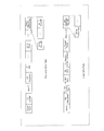
- FIG. 14 shows an example of allocating a 20 MHz band to STA1, a 20 MHz band to STA2, and a 40 MHz band (in other words, resources) to STA # 3 in the configuration example of the wireless communication system shown in FIG. It is a figure.
- AP1 and AP2 may transmit the same (common) information to STA1, STA2, and STA3 in the band of 80 MHz.
- STA1, STA2 and STA3 may transmit an uplink response signal (eg, TBPPDU), for example, in the band indicated by the Trigger frame.
- AP1 and AP2 may transmit an ACK (or BA) to each STA, for example, in the band in which the uplink response signals from STA1, STA2, and STA3 are transmitted.
- ACK or BA
- the AP100 may select the maximum target RSSI among the target RSSIs for each STA200 set by each AP100 that performs cooperative communication.
- target RSSI For example, if the target RSSI set for STA2 by AP1 is RSSI # 1 and the target RSSI set for STA2 by AP2 is RSSI # 2, the value of max (RSSI # 1, RSSI # 2) is STA2. may be selected for target RSSI.
- the uplink response signal in the AP100 You can improve the probability of successful reception.
- the AP100 may select the minimum target RSSI among the target RSSIs for each STA200 set by each AP100 that performs cooperative communication.
- target RSSI For example, if the target RSSI set for STA2 by AP1 is RSSI # 1 and the target RSSI set for STA2 by AP2 is RSSI # 2, the value of min (RSSI # 1, RSSI # 2) is STA2. may be selected for target RSSI.
- the minimum target RSSI for the target RSSI of the STA200 it is possible to reduce the interference (for example, Adjacent-channel interference (ACI)) that the uplink response signal transmitted from the STA200 gives to the response signals of other STAs. Therefore, it is possible to improve the probability that the AP100 succeeds in receiving the response signal of another STA.
- ACI Adjacent-channel interference
- the AP100 may select the average value of the target RSSI for each STA200 set by each AP100 that performs cooperative communication.
- the average value for the target RSSI of the STA200 it is possible to suppress the ACI given to other STAs by the uplink response signal transmitted from the STA200 while maintaining the reception performance of the uplink response signal in the AP100.
- the AP100 may calculate the average value by weighting the target RSSI set for each of the STA200s, for example.
- the weighting coefficient may be increased for the target RSSI of Sharig AP, and the weighting coefficient may be decreased for the target RSSI of Shared AP.
- the selection methods 1 to 3 have been explained above.
- the method of selecting the target RSSI for each STA200 when the uplink cooperative communication is applied is not limited to the above-mentioned selection methods 1 to 3.
- the target RSSI for the STA200 may be set based on any one or more of the targetRSSIs set in the STA200 in each AP100.
- Trigger frame format for uplink cooperative communication and calculation method of uplink transmission power [Trigger frame format for uplink cooperative communication and calculation method of uplink transmission power]
- Trigger frame format for uplink cooperative communication and the method of calculating (determining) the uplink transmission power in the STA200 according to the present embodiment will be described.
- the information regarding the transmission power of the AP100 may be set for each STA200 by the Trigger frame.
- the transmission power control parameter may include information on downlink transmission power determined for each of the plurality of STA200s according to the type of uplink communication control (for example, multi-AP control) based on communication between AP100s.
- the type of multi-AP control for each STA200 may include, for example, a case of performing coordinated uplink communication control and a case of performing coordinated uplink communication control.
- Joint transmission and Diversity reception may be included.
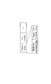
- FIG. 15 is a diagram showing an example of the Common Info field and the User Info field of the Trigger frame in Example 1.
- the Common Info field and User Info field of the Trigger frame may include fields different from the fields shown in FIG. Further, a part of the field shown in FIG. 15 may not be included.
- a set value (for example, also referred to as a reference value) of the transmission power of the AP100 commonly used when a plurality of STA200s to be transmitted in the Trigger frame calculate the uplink transmission power “AP”.
- TX Power may be included.
- the "AP TX Power” includes, for example, the transmission power of the sharing AP, the average value of the transmission power of the AP 100 belonging to the AP group for coordinated communication (for example, also referred to as the average transmission power), or the transmission power of the AP 100 belonging to the AP group. Any one of the above (for example, the maximum value or the minimum value) may be set.
- the User Info field shown in FIG. 15 includes, for example, an offset value (for example, “AP TX Power offset”) with respect to the value “AP TX Power” common to a plurality of STA200s included in the Common Info field. good.
- an offset value for example, “AP TX Power offset”
- the value of "APTXPower offset” may be a negative value. Therefore, for example, when the field of "AP TX Power offset" is 4 bits, an offset value such as -8 to +7 [dB] may be set.
- the AP100 may determine the APTXPower offset, for example, based on the cooperative communication mode (for example, Diversity reception, joint reception, etc.). For example, in the selection of the cooperative communication mode, Joint reception may be applied between a plurality of AP100s in which the path loss between the STA 200 and the AP 100 is within X dB. On the other hand, between a plurality of AP100s having a path loss larger than XdB, for example, diversity reception by one AP100 having the smallest path loss may be applied.
- the cooperative communication mode for example, Diversity reception, joint reception, etc.
- the STA200 can calculate the downlink path loss by using the transmission power synthesized between a plurality of AP100s participating in the Joint reception.
- the transmission power (TxPow AP1 [dBm]) of the Sharing AP (AP1) may be set in the setting value of "AP TX Power" in the Common Info field.
- 0 [dB] may be set in the setting value of "AP TX Power offset" in the User Info field for STA1.
- the set value of "APTXPower offset” for STA1 may be set to a value obtained by subtracting APTXPower (here, transmission power of AP1) from the transmission power of AP1.
- the setting value of "AP TX Power offset" in the User Info field for STA2 is, for example, the transmission power of AP1 and AP2 as shown in the following equation (3) in consideration of the joint reception by AP1 and AP2.
- the value obtained by subtracting AP TX Power (here, the transmission power of AP1) from the combined power of is set.
- the setting value of "AP TX Power offset" in the User Info field for STA3 is, for example, from the transmission power of AP2 to AP TX Power (here, the transmission power of AP1) as shown in the following equation (4).
- the value obtained by subtracting is may be set.
- Tx Pow STA200 Trigger "AP TX Power” in Common Info field in the frame (for example, expressed as Tx Pow Ap), and, "AP Tx Power offset" of User Info field (for example, expressed as Tx PowOffset Ap)
- the uplink transmission power (for example, expressed as Tx Pow STA ) may be calculated according to the following equations (5) and (6) based on the set value.
- the uplink transmission power based on the transmission power of AP1 is set for STA1
- the uplink transmission power based on the combined value of the transmission power of AP1 and AP2 is set for ST2.
- the uplink transmission power based on the transmission power of AP2 is set for STA3.
- the AP100 uses, for example, a Trigger frame to provide information on the transmission power considering the cooperative communication mode for each STA200 (in other words, the transmission power of the AP100 considering the MAP coordination processing for each STA200).
- the STA200 can recognize, for example, the transmission power of the AP100 in consideration of the cooperative communication mode based on the received Trigger frame. For example, even if the transmission powers of the plurality of AP100s are different, the AP100 can notify the information regarding the transmission power of the AP100 according to the uplink transmission method (for example, the cooperative communication mode) of each STA200 by the Trigger frame. Therefore, even when the cooperative communication mode is applied, each STA200 can improve the estimation accuracy of the downlink path loss and can correctly calculate (determine) the uplink transmission power, so that the uplink throughput can be improved.
- the uplink transmission method for example, the cooperative communication mode
- the "AP TX Power offset" of the User Info field applied in the uplink cooperative communication mode is shown in FIG. 16, for example. It may be placed in the Trigger Dependent User Info field.
- FIG. 17 is a diagram showing an example of the Common Info field and the User Info field of the Trigger frame in Example 2.
- the Common Info field and User Info field of the Trigger frame may include fields different from the fields shown in FIG. Further, a part of the field shown in FIG. 17 may not be included.
- APTXPower field for example, APTXPower field
- APTxPower a set of transmission power (for example, APTxPower) considering a cooperative communication mode for each STA200 (for example, Diversity reception or joint reception) is used. # 1 to APTxPower # N) may be included.
- the Common Info field contains the transmission power of AP1, the transmission power of AP2, and the combined transmission power of AP1 and AP2 in consideration of joint reception (for example, “AP #”.
- a set of 1 + AP # 2 transmit power) may be included.
- the number of sets N of transmission power of the AP100 may be determined by, for example, any of the following methods.
- the value of the number of sets N may be a fixed value.
- the value of the number of sets N may be predetermined (or defined) in the specifications, for example.
- the fixed value may be, for example, a value based on the maximum number of AP100s that perform expected coordinated communication, or the maximum number of AP100s considering the combination of AP100s in the joint reception.
- the value of the number of sets N may be a value notified (in other words, set) from AP100 to STA200.
- the value of the number of sets N may be notified by, for example, a beacon in the Negotiation phase or control information.
- the AP100 can reduce the signaling overhead by notifying the set number N in consideration of the cooperative communication in the AP group.
- the User Info field shown in FIG. 17 may include, for example, an index (for example, AP TX Power index) indicating which value of the transmission power set included in the Common Info field is used by the STA200. ..
- the UserInfofield may include an index associated with information about a plurality of downlink transmission powers set in the CommonInfofield.
- the transmission power of AP1 is set in APTxPower # 1
- the transmission power of AP2 is set in APTxPower # 2
- the transmission power of AP2 is set in APTxPower # 3.
- the index # 1 may be set in the UserInfo field for STA1
- the index # 3 may be set in the UserInfo field for STA2
- the index # 2 may be set in the UserInfo field for STA3.
- the uplink transmission power (for example, expressed as Tx Pow STA ) may be calculated according to the following equations (7) and (8) based on the set value of the Tx Power index (for example, expressed as i).
- the uplink transmission power based on the transmission power of AP1 is set for STA1
- the uplink transmission power based on the combined value of the transmission power of AP1 and AP2 is set for ST2.
- the uplink transmission power based on the transmission power of AP2 is set for STA3.
- the AP100 uses, for example, a Trigger frame to provide information on the transmission power considering the cooperative communication mode for each STA200 (in other words, the transmission power of the AP100 considering the MAP coordination processing for each STA200).
- the STA200 can recognize, for example, the transmission power of the AP100 in consideration of the cooperative communication mode based on the received Trigger frame. For example, even if the transmission powers of the plurality of AP100s are different, the AP100 can notify the information regarding the transmission power of the AP100 according to the uplink transmission method (for example, the cooperative communication mode) of each STA200 by the Trigger frame. Therefore, even when the cooperative communication mode is applied, each STA200 can improve the estimation accuracy of the downlink path loss and can correctly calculate (determine) the uplink transmission power, so that the uplink throughput can be improved.
- the uplink transmission method for example, the cooperative communication mode
- the index value has a smaller number of bits as in Example 2 as compared with the offset value as in Example 1 (for example, FIG. 15). Prone. Also, in general, in a wireless communication system, there is a high possibility that the number of STA200s is larger than the number of AP100s. Therefore, in Example 2, for example, the larger the number of STA200s set (in other words, the trigger) by the Trigger frame, the more the increase in UserInfofield size can be suppressed as compared with Example 1. The signaling overhead can be further reduced.
- the "AP TX Power # 2 to AP TX Power # N" of the Common Info field applied in the uplink cooperative communication mode is For example, as shown in FIG. 18, it may be arranged in the Trigger Dependent Common Info field.
- APTXPower # 1 may be arranged in the APTXPower field shown in FIG.
- the “APTXPowerindex” of the UserInfofield applied in the uplink cooperative communication mode may be arranged in the TriggerDependentUserInfofield as shown in FIG.
- Trigger frame format switching method Next, a method of switching between the control signal format (Trigger frame format) when the uplink cooperative communication is applied and the control signal format when the uplink cooperative communication is not applied (in other words, a format notification method to the STA200) will be described.
- the format switching may be read as a format selection or a format determination or setting.
- the format of the control signal at the time of applying uplink cooperative communication may be applied.
- the AP100 and STA200 may switch the format of the trigger frame based on any of the switching methods 1 to 6 described below.
- AP100 and STA200 apply A uplink coordinated communication control (eg, uplink communication control coordinated between AP100s) based on information regarding coordination of multi-AP control (for example, flag information or Trigger type described later).
- the Trigger frame format in the case and the Trigger frame format in the case where the uplink cooperative communication control is not performed may be determined. As a result, it is possible to reduce the signaling overhead when a plurality of STA200s whose uplink response signals are instructed by the Trigger frame do not perform uplink cooperative communication.
- the AP100 may notify the STA200 of the control information including the flag information indicating whether or not the uplink cooperative communication is performed.
- information indicating whether or not uplink cooperative communication is applied may be included in the Common Info field (for example, "UL multi AP flag").
- the control signal format for STA200 at the time of uplink cooperative communication as in Example 1 or Example 2 may be applied.
- the format of the control signal for STA200 at the time of uplink cooperative communication does not have to be applied.
- the same control signal format as 11ax may be applied.
- the STA200 may determine which format is applied to the Trigger frame (control signal) based on the UL multi AP flag of the Common Info field.
- the AP100 controls the STA200 during uplink cooperative communication in the signal field (for example, Universal-SIG (U-SIG) or EHT-SIG) in the preamble of the downlink PPDU including the Trigger frame.
- the signal field for example, Universal-SIG (U-SIG) or EHT-SIG
- Information indicating whether or not to apply the signal format may be notified.
- the AP100 has information indicating whether or not to apply the format of the control signal for the STA200 at the time of uplink cooperative communication in the beacon or the control information (for example, the UL multi AP flag similar to the switching method 1). ) May be notified to STA200.
- the AP100 may instruct the STA200 to format the control signal by the "Trigger type" included in the Common Info field of the Trigger frame.
- the multi-AP application mode may be set for at least one of the modes such as Basic and Beamforming Report Poll (BFRP).
- BFRP Basic and Beamforming Report Poll
- FIG. 20 is a diagram showing an example of the Trigger type according to the switching method 4.
- FIG. 20 shows, for example, a Trigger type (for example, Trigger frame variant) and a value (Trigger type subfield value) associated with the Trigger type notified from the AP100 to the STA200 by the Trigger frame (for example, Common Infofield). An example of the relationship is shown.
- Trigger Type subfield value 8
- the combination of Basic and multi-AP application modes is set to Trigger type.
- the Trigger type setting shown in FIG. 20 is an example, and a Trigger frame type different from Basic and a multi-AP application mode may be notified.
- the Trigger frame format when uplink cooperative communication is applied may be set.
- the AP100 may instruct the STA200 to format the control signal by the "Trigger type" included in the Common Info field of the Trigger frame.
- FIG. 21 is a diagram showing an example of the Trigger type according to the switching method 5.
- the AP100 uses a field different from the Trigger Type subfield value (for example, Multi-AP operation flag (for example, 1 bit)) to determine whether or not the AP100 is in the Trigger format for uplink cooperative communication to the STA200. You may notify me.
- the Trigger Type subfield value for example, Multi-AP operation flag (for example, 1 bit)
- the AP100 may instruct the STA200 to format the control signal by the "Trigger type" included in the Common Info field of the Trigger frame.
- FIG. 22 is a diagram showing an example of the Trigger type according to the switching method 6.
- FIG. 22 shows, for example, a Trigger type (for example, Trigger frame variant) and a value (Trigger type subfield value) associated with the Trigger type notified from the AP100 to the STA200 by the Trigger frame (for example, Common Infofield). An example of the relationship is shown.
- Trigger type for example, it may be notified that uplink cooperative communication (multi-AP) is performed.
- Trigger Type subfield value 8
- Trigger Info may be notified in a field different from Trigger type (for example, Trigger Info of Trigger Dependent Common Info field).
- Trigger format notified in Trigger Info may be the same as the content shown in FIG. 5 (for example, Trigger type of 11ax).
- the Trigger frame format at the time of application of uplink cooperative communication may be set.
- the AP100 notifies the STA200 of the parameters related to the uplink transmission power control (for example, the parameters related to the transmission power of the AP100 for each STA200) when performing the uplink cooperative communication by the Trigger frame. Further, the STA200 controls the transmission power of the uplink response signal, for example, based on the parameters related to the uplink transmission power control included in the received Trigger frame.
- the STA200 controls the transmission power of the uplink response signal, for example, based on the parameters related to the uplink transmission power control included in the received Trigger frame.
- each STA200 can calculate the transmission power of the uplink response signal based on the transmission power control parameter (transmission power of AP100) for each STA200 included in the Trigger frame. Therefore, for example, even if the transmission powers of the plurality of AP100s in the AP group are different, each STA200 can improve the estimation accuracy of the downlink path loss and improve the accuracy of the transmission power control of the uplink response signal. Throughput can be improved.
- the uplink transmission power can be flexibly set (controlled) for each STA200 in the Multi-AP coordination.
- the configuration example of AP100 and STA200 according to the present embodiment may be the same as the configuration example of the first embodiment.
- the Trigger frame format for uplink cooperative communication and the calculation method of uplink transmission power according to this embodiment will be described.
- the Trigger frame format may be switched in the same manner as in the first embodiment (for example, any of the switching method 1 to the switching method 6).
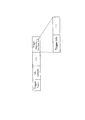
- FIG. 24 is a diagram showing an example of the Common Info field and the User Info field of the Trigger frame in Example 3.
- the Common Info field and User Info field of the Trigger frame may include fields different from the fields shown in FIG. 24. Further, a part of the field shown in FIG. 24 may not be included.
- the Common Info field (for example, APTXPower field) shown in FIG. 24 may include, for example, the transmission power for each AP100 in the AP group (for example, APTXPower # 1 to APTXPower # N).
- N may be a fixed value, for example, as in Example 2 of the first embodiment, or may be notified from the AP100 to the STA200 by a beacon or control information. Further, when the number of AP100 in the AP group is less than N, there may be an unused area in the APTXPower field.
- the transmission power of AP1 may be set in APTXPower # 1 and the transmission power of AP2 may be set in APTXPower # 2.
- the User Info field shown in FIG. 24 may include, for example, an “AP TX Power index” having a bit number (N) similar to the number N of transmission power for each AP 100 set in the Common Info field. ..
- the N bit of APTXPowerindex may be bitmap information corresponding to each of APTXPower # 1 to APTXPower # N.
- the upstream transmission power may be calculated using Power.
- the STA200 may calculate the uplink transmission power by synthesizing the values of the plurality of APTXPower corresponding to each of the plurality of bits. For example, when Joint reception is applied, a plurality of APTXPowerindex corresponding to each of the plurality of AP100s receiving the uplink response signal from the STA200 may be set to 1.
- the uplink transmission power (for example, expressed as Tx Pow STA ) may be calculated according to the following equations (9), (10) and (11) based on the set value of the Tx Power index (for example, expressed as i). ..
- the STA200 has, for example, a value Tx Pow obtained by adding the transmission power Tx Pow Ap (i) of the AP100 in which the value of the AP Tx Power index (i) is set to 1.
- the transmission power of AP1 is set in APTxPower # 1
- the transmission power of AP2 is set in APTxPower # 2
- N 2 bits
- "10” is set in the APTXPowerindex of the UserInfofield of STA1
- "11” is set in the APTXPowerindex of the UserInfofield of STA2
- the AP of the UserInfofield of STA3 is set.
- "01" may be set in the TXPowerindex.
- STA1 calculates the uplink transmission power based on the transmission power of AP1
- ST2 calculates the uplink transmission power based on the combined value of the transmission power of AP1 and AP2
- STA3 calculates the uplink transmission power. , Calculates the uplink transmission power based on the transmission power of AP2.
- the transmission power of each AP100 in the AP group is set (in other words, notification) by the Trigger frame.
- the STA200 can recognize, for example, the transmission power of the AP100 in consideration of the cooperative communication mode based on the received Trigger frame. For example, even if the transmission powers of a plurality of AP100s are different, the STA200 can recognize (or select) information regarding the transmission power of the AP100 according to the uplink transmission method (for example, cooperative communication mode) of each STA200 by the Trigger frame. .. Therefore, even when the cooperative communication mode is applied, each STA200 can improve the estimation accuracy of the downlink path loss and can correctly calculate (determine) the uplink transmission power, so that the uplink throughput can be improved.
- the uplink transmission method for example, cooperative communication mode
- the Common Infofield "AP TX Power # 2 to AP TX” applied in the uplink cooperative communication mode is applied.
- "Power # N” may be arranged in the Trigger Dependent Common Info field as shown in FIG. 25, for example.
- APTXPower # 1 may be placed in the APTXPower field shown in FIG. 25.
- the “AP TX Power index” of the User Info field applied in the uplink cooperative communication mode may be arranged in the Trigger Dependent User Info field as shown in FIG. 25.
- Example 4 for example, as in Example 3, the transmission power for each AP 100 in the AP group (for example, AP TX Power # 1 to AP TX Power # N) may be included in the Common Info field of the Trigger frame.
- Example 4 for example, in the User Info field of the Trigger frame, information regarding the transmission power of the AP100 used for calculating the uplink transmission power (for example, in Example 3, "APTXPowerindex") is not instructed. good.
- UserInfofield may have the same format as 11ax.
- the STA200 may select, for example, the transmission power used for calculating the uplink transmission power from the transmission powers of the plurality of AP100s notified in the Common Info field of the Trigger frame.
- the STA200 estimates the path loss in communication with each AP100, and based on the transmission power for each AP100 notified in the Common Info field and the estimated path loss, the uplink transmission power for each transmission destination (AP100). May be calculated.
- the EHT-LTF between AP100s of the AP group may be orthogonal to each other for path loss estimation with each AP100.
- a method of making the EHT-LTF orthogonal for example, a method using different frequency resources or different codes (for example, an orthogonal code) may be applied.
- the STA200 may estimate the path loss between each AP100 without using, for example, the orthogonal EHT-LTF. For example, it is assumed that the path loss difference between AP100s performing cooperative communication is small (for example, when the path loss difference is equal to or less than the threshold value). Therefore, the STA200 assumes that there is no difference between the path losses corresponding to each of the plurality of AP100s (for example, below the threshold value), and estimates the path loss estimated based on the non-orthogonal EHT-LTF as the path loss of each AP100. You may.
- the STA200 may determine the final uplink transmission power by, for example, one of the following selection methods, based on the uplink transmission power calculated for each transmission destination (AP100).
- the STA200 may select, for example, the minimum uplink transmission power from the calculated uplink transmission power. By selecting the minimum uplink transmission power, the power consumption of the STA200 can be suppressed.
- the STA200 may select, for example, the maximum uplink transmission power from the calculated uplink transmission power. By selecting the maximum uplink transmission power, the reception quality of the uplink response signal can be improved and the uplink throughput can be improved.
- the STA200 may set, for example, the calculated average value of the uplink transmission power to the transmission destination (AP100) as the uplink transmission power. Thereby, for example, the power consumption of the STA200 can be suppressed and the reception quality of the uplink response signal can be improved.
- the method of selecting the uplink transmission power is not limited to these.
- the average value weighted with respect to the calculated uplink transmission power of the transmission destination (AP100) may be set as the uplink transmission power.
- the transmission power of each AP100 in the AP group is set (in other words, notification) by the Trigger frame.
- the STA200 can recognize, for example, the transmission power of the AP100 in consideration of the cooperative communication mode based on the received Trigger frame. For example, even if the transmission powers of a plurality of AP100s are different, the STA200 can recognize (or select) information regarding the transmission power of the AP100 according to the uplink transmission method (for example, cooperative communication mode) of each STA200 by the Trigger frame. .. Therefore, even when the cooperative communication mode is applied, each STA200 can improve the estimation accuracy of the downlink path loss and can correctly calculate (determine) the uplink transmission power, so that the uplink throughput can be improved.
- the uplink transmission method for example, cooperative communication mode
- Example 4 for example, in the STA200, the AP100 addressed to transmission can be dynamically switched (for example, Diversity reception), so that the reception quality of the uplink response signal can be improved or the power consumption can be reduced.
- the AP100 addressed to transmission can be dynamically switched (for example, Diversity reception), so that the reception quality of the uplink response signal can be improved or the power consumption can be reduced.
- the AP100 notifies the STA200 of the parameters related to the uplink transmission power control in consideration of the uplink cooperative communication (for example, the parameters related to the uplink transmission power control for each of the plurality of STA200s) by the Trigger frame. Further, the STA200 controls the transmission power of the uplink response signal, for example, based on the parameters related to the transmission power control included in the received Trigger frame.
- each STA200 can calculate the transmission power of the uplink response signal based on the transmission power control parameter (transmission power of AP100) for each AP100 included in the Trigger frame. Therefore, for example, even if the transmission powers of the plurality of AP100s in the AP group are different, each STA200 can improve the estimation accuracy of the downlink path loss, so that the accuracy of the transmission power control of the uplink response signal can be improved, and the uplink can be improved. Throughput can be improved.
- the uplink transmission power for each STA200 can be flexibly set (controlled) in the Multi-AP coordination.
- the configuration example of AP100 and STA200 according to the present embodiment may be the same as the configuration example of the first embodiment.
- the operation of the control signal generation unit 102 for STA of the AP100 is different from that of the first embodiment or the second embodiment, an operation example will be described below.
- the control signal generation unit 102 for STA is, for example, a resource allocation result to each STA 200, a transmission power control parameter (for example, APTXPower or targetRSSI, etc.) input from the setting unit 101, or a reception signal demodulation / decoding unit.
- a control signal for the STA200 may be generated based on the information input from 106.
- the control signal for the STA200 includes, for example, time and frequency resource information (eg, RU allocation information for uplink cooperative communication, TXOP, LENGTH, etc.), as well as transmission power control parameters (eg, transmission power of AP100, or transmission power).
- time and frequency resource information eg, RU allocation information for uplink cooperative communication, TXOP, LENGTH, etc.
- transmission power control parameters eg, transmission power of AP100, or transmission power.
- At least one of target RSSI, etc.), information related to trigger frame generation (for example, ULMCS, GI, LTF mode), Trigger type for notifying the type of control signal, and terminal identification information (for example, AID) may be included. ..
- the dynamic range of the target RSSI may be larger than that in the case where the uplink cooperative communication is not applied. Therefore, in the present embodiment, when the uplink cooperative communication is applied, the format of the target RSSI field may be changed as compared with the case where the uplink cooperative communication is not applied (an example will be described later).
- the control signal generation unit 102 for STA outputs, for example, the generated control signal to the transmission signal generation unit 104.
- the AP100 is, for example, based on the "APTXPower" set in the Common Infofield of the Trigger frame, the transmission power of each AP100 in the AP group, and the cooperative communication mode applied to each STA200, and the "target" of the UserInfofield. You may adjust "RS SI".
- AP100 may adjust the target RSSI according to the following equation (12).
- Target RSSI_adj (u) represents the adjusted target RSSI [dBm] for STA # u
- Target RSSI (u) represents the unadjusted target RSSI [dBm] for STA # u.
- the target RSSI before adjustment may be, for example, a target RSSI set by the same method as in the first embodiment or the second embodiment.
- Tx Pow Ap represents AP TX Power [dBm] set in the Common Info field
- Tx Pow Ap (u) receives the uplink response signal transmitted from STA # u. Represents the transmission power [dBm] of at least one AP100.
- the transmission power of the sharing AP may be set in the Tx Pow Ap.
- the value of Tx Pow Ap is not limited to the transmission power of the sharing AP, but may be the average transmission power of the AP group for cooperative communication, and the transmission power of any AP100 in the AP group (for example, the maximum or minimum transmission). (Electric power) may be used.
- the transmission power of the association AP may be set in the Tx Pow Ap (u) for the STA 200 that does not perform uplink cooperative communication.
- the transmission power of the AP100 for receiving the uplink response signal may be set.
- the total value of the transmission powers of a plurality of AP100s that receive uplink response signals may be set.
- the adjusted target RSSI (Target RSSI_adj (u)) reflects, for example, the transmission power of one or more AP100s that perform cooperative communication. Therefore, the STA200 can calculate the uplink transmission power according to the cooperative communication mode set for each STA200, for example, based on the target RSSI notified by the Trigger frame.
- a format that enables notification of the desired target RSSI in the User Info field of the Trigger frame may be applied.
- the AP100 can notify the STA200 of the desired target RSSI, so that the accuracy of the uplink transmission power control in the STA200 can be improved. ..
- the Trigger frame format may be switched in the same manner as in the first embodiment (for example, any of the switching method 1 to the switching method 6).
- the number of bits corresponding to the set value of target RSSI may be increased in the target RSSI field.
- the number of bits in the target RSSI field is 7 bits.
- the number of bits may be larger than 7 bits (for example, 8 bits) in consideration of an increase in the dynamic range of Target RSSI due to uplink cooperative communication.
- the bit size corresponding to the information related to the target RSSI may differ depending on whether the uplink cooperative communication control (for example, the uplink communication control coordinated between AP100s) is performed or the uplink cooperative communication control is not performed.
- the uplink cooperative communication control for example, the uplink communication control coordinated between AP100s
- a part of the Reserve area set in the target RSSI field (for example, a table) in 11ax shown in FIG. 4 may be used as an increase in bits corresponding to the target RSSI setting value. In this case, it is not necessary to increase the number of bits in the target RSSI field.
- FIG. 27 shows an example of a target RSSI field (eg, a table).
- FIG. 20 shows, for example, a target RSSI value (or a candidate value, for example, in the range of -155 dBm to 25 dBm) and an index value (for example, 0-) notified from AP100 to STA200 by a Trigger frame (for example, User Info field).
- a Trigger frame for example, User Info field
- the range of the target RSSI that can be set may be expanded by increasing the step width of the target RSSI as compared with the set value shown in FIG. 4 (for example, increasing the maximum value). And reduce the minimum value).
- the step width of target RSSI is 1 dB step in 11ax and 2 dB step in FIG. 27.
- the difference between the target RSSIs (in other words, the step width) associated with each of the two indexes associated with the candidate values of the target RSSI is the uplink coordinated communication control (for example, the uplink communication coordinated between the AP100s). Control) may be different from the case where the uplink cooperative communication control is not performed.
- FIG. 27 is an example, and for example, the range of either the maximum value or the minimum value may be expanded, and the step width may be a step width different from 2 dB (for example, 1.5 dB).
- the STA200 may be switched based on the setting value of the "AID12" field of the UserInfo field. For example, when an AID separately reserved for cooperative communication (for example, AID for cooperative communication) is instructed, the STA200 applies a target RSSI table (for example, FIG. 27) in which the step width of RSSI is increased, and the cooperative communication is performed. If an AID different from the target AID is specified, a target RSSI table with an RSSI step width of 1 dB (for example, FIG. 4) may be used. In other words, the STA200 may change the step width or range (maximum value, minimum value) of the target RSSI based on the AID indicated by the Trigger frame, for example.
- the cooperative communication AID may be, for example, any AID of 2047 to 4094 reserved in 11ax, or may be an AID instructed by a beacon or control information.
- the notification method of target RSSI in consideration of the uplink coordinated communication control the accuracy of the uplink transmission power control in the uplink coordinated communication can be improved as in the first embodiment and the second embodiment.
- the target RSSI notification method may be changed with respect to the control signal notification method in 11ax, so that the change in specifications can be suppressed.
- each AP100 generates a Trigger frame for each AP100 (in other words, a Trigger frame for each AP100), and a method of controlling the uplink transmission power for uplink cooperative communication by a plurality of Trigger frames will be described. ..
- control signal generation unit 102 for STA of the AP100 is different from that of other embodiments, so an operation example will be described below.
- the control signal generation unit 102 for STA is, for example, a resource allocation result to each STA 200, a transmission power control parameter (for example, APTXPower or targetRSSI, etc.) input from the setting unit 101, or a reception signal demodulation / decoding unit.
- a control signal for the STA200 may be generated based on the information input from 106.
- the control signal for the STA200 includes, for example, time and frequency resource information (for example, RU allocation information for uplink cooperative communication, TXOP, LENGTH, etc.), as well as transmission power control parameters (for example, transmission power of AP100, or target). At least one of RSSI etc.), information on trigger frame generation (for example, ULMCS, GI, LTF mode), Trigger type for notifying the type of control signal, and terminal identification information (for example, AID) may be included.
- time and frequency resource information for example, RU allocation information for uplink cooperative communication, TXOP, LENGTH, etc.
- transmission power control parameters for example, transmission power of AP100, or target.
- At least one of RSSI etc. information on trigger frame generation (for example, ULMCS, GI, LTF mode), Trigger type for notifying the type of control signal, and terminal identification information (for example, AID) may be included.
- control signal generation unit 102 for STA may individually generate Trigger frames for the number of APs in the AP group, for example.
- control signal generation unit 102 for STA may generate a Trigger frame in units of AP100 in the AP group, for example.
- a configuration example of the Trigger frame will be described later.
- the control signal generation unit 102 for STA outputs, for example, a plurality of generated control signals to the transmission signal generation unit 104.
- Trigger frame configuration example Hereinafter, a configuration example of the Trigger frame according to the present embodiment will be described.
- the User Info field of the Trigger frame corresponding to each AP100 relates to the STA200 (in other words, the STA200 that sets the corresponding AP100 to the transmission destination) for receiving the uplink response signal in the corresponding AP100.
- Information may be included.
- the same AID may be set in each of the Trigger frames of the plurality of AP100s that receive the uplink response.
- FIG. 28 is a diagram showing a configuration example of the Trigger frame according to the configuration example 1.
- the Trigger frame may be generated for each AP100 (for example, AP1 and AP2).
- the Trigger frame for AP1 may include the User Info field of each of STA1 and STA2.
- the Trigger frame for AP2 may include the User Info field of each of STA2 and STA3.
- the STA200 decodes a plurality of Trigger frames in the received downlink PPDU (for example, EHT PPDU or MU PPDU), and the target RSSI set in the User Info field including the AID addressed to the STA200 and the AID addressed to the STA200.
- Upstream transmission power control may be performed based on APTXPower included in the CommonInfofield of the Trigger frame that includes.
- STA1 is the target RSSI set in the User Info field for STA1 included in the Trigger frame for AP1, and the AP TX Power set in the Common Info field of the Trigger frame for AP1.
- the uplink transmission power may be calculated based on.
- STA3 is transmitted upstream based on the target RSSI set in the User Info field for STA3 included in the Trigger frame for AP2 and the AP TX Power set in the Common Info field of the Trigger frame for AP2. The power may be calculated.
- STA2 is a target RSSI set in the User Info field for STA2 included in each Trigger frame for AP1 and AP2, and Common Info for each Trigger frame for AP1 and AP2.
- the uplink transmission power may be calculated based on the APTXPower set in the field.
- the STA200 corresponding to the AID is, for example, the value obtained by adding the AP TX Power of each Trigger frame.
- the upstream transmission power may be calculated as the transmission power.
- the STA200 corresponding to the AID is, for example, the average value, the maximum value, or the maximum value of the target RSSI when the target RSSI set in each UserInfofield is different. You may select the minimum target RSSI.
- the STA200 can recognize the transmission power of each AP100, for example, can control the uplink transmission power in consideration of the cooperative communication mode, and can improve the uplink throughput.
- Configuration Example 2 differs from Configuration Example 1 in the method of notifying the transmission power control parameter when Joint transmission is applied.
- information indicating whether or not the cooperative communication mode (for example, Joint transmission) is applied may be set in the UserInfo field.
- the configuration example 2 for example, it is not necessary to notify a plurality of AIDs (for example, the same AID) in the Trigger frame corresponding to each of the plurality of AP100s.
- the User Infofield corresponding to each of the plurality of AIDs may be set to any one of the Trigger frames corresponding to the plurality of AP100s.
- FIG. 29 is a diagram showing a configuration example of the Trigger frame according to the configuration example 2.
- the Trigger frame may be generated for each AP100 (for example, AP1 and AP2).
- the Trigger frame for AP1 may include the User Info field of each of STA1 and STA2.
- the Trigger frame for AP2 may include the User Info field of each STA3.
- the STA 200 transmits the value obtained by adding the AP TX Power of a plurality of Trigger frames included in the PPDU.
- the upstream transmission power may be calculated as the power.
- the STA200 is instructed to use a mode different from the Joint transmission (for example, no cooperative communication or diversity reception, etc.) in the multi-AP mode field included in the User Info field for the STA200, the STA200
- the uplink transmission power may be calculated based on the APTXPower set in the CommonInfofield of the Trigger frame whose AID is included in the UserInfofield.
- a mode different from Joint transmission is specified in the multi-AP mode field for STA1. Therefore, the STA1 may calculate the uplink transmission power based on the APTXPower set in the CommonInfofield of the Trigger frame for the AP1 including the UserInfofield for the STA1.
- a mode different from Joint transmission is indicated in the multi-AP mode field for STA3. Therefore, the STA3 may calculate the uplink transmission power based on the APTXPower set in the CommonInfofield of the Trigger frame for the AP2 including the UserInfofield for the STA3.
- STA2 may calculate the uplink transmission power based on the added value of APTXPower set in the CommonInfofield of each Triggerframe for a plurality of APs (AP1 and AP2).
- the STA200 can recognize the transmission power of each AP100, can control the uplink transmission power in consideration of the cooperative communication mode, and can improve the uplink throughput. Further, in the configuration example 2, since the User Infofield corresponding to the same AID is not set in a plurality of Trigger frames, for example, the larger the number of STA200s that perform joint reception, the overhead of signaling as compared with the first embodiment. Can be reduced.
- each of the plurality of AP100s allocates downlink PPDUs including a Trigger frame corresponding to each AP100 to different frequency resources and transmits them.
- control signal generation unit 102 for STA of the AP100 is different from that of other embodiments, so an operation example will be described below.
- the control signal generation unit 102 for STA is, for example, a resource allocation result to each STA 200, a transmission power control parameter (for example, APTXPower or targetRSSI, etc.) input from the setting unit 101, or a reception signal demodulation / decoding unit.
- a control signal for the STA200 may be generated based on the information input from 106.
- the control signal for the STA200 includes, for example, time and frequency resource information (for example, RU allocation information for uplink cooperative communication, TXOP, LENGTH, etc.), as well as transmission power control parameters (for example, transmission power of AP100, or target). At least one of RSSI etc.), information on trigger frame generation (for example, ULMCS, GI, LTF mode), Trigger type for notifying the type of control signal, and terminal identification information (for example, AID) may be included.
- time and frequency resource information for example, RU allocation information for uplink cooperative communication, TXOP, LENGTH, etc.
- transmission power control parameters for example, transmission power of AP100, or target.
- At least one of RSSI etc. information on trigger frame generation (for example, ULMCS, GI, LTF mode), Trigger type for notifying the type of control signal, and terminal identification information (for example, AID) may be included.
- control signal generation unit 102 for STA generates, for example, a control signal for STA200 associated with each AP100.
- Each AP100 in the AP group may be assigned a downlink PPDU including a Trigger frame, for example, in different frequency resources.
- FIG. 30 is a diagram showing an example of resource allocation of a PPDU (for example, EHT PPDU or MU PPDU) including a Trigger frame.
- the example shown in FIG. 30 shows resource allocation in the case of the configuration example of the wireless communication system shown in FIG.
- AP1 may assign a downlink PPDU including a Trigger frame to a 40 MHz channel including a primary channel (P20 for AP1) for AP1 and transmit it.
- AP # 2 may assign a downlink PPDU including a Trigger frame to a 40 MHz channel including a primary channel (P20 for AP2) for AP2 and transmit it.
- the STA200 receives, for example, the Trigger frame from AP1 and the Trigger frame from AP2 at different frequency resources.
- the configuration of the Trigger frame when performing cooperative communication may be, for example, the same as any of the configuration example 1 and the configuration example 2 of the fourth embodiment.
- a User Info field in which the AID of the STA 200 to which the joint reception is applied may be set for each Trigger frame from each AP 100 may be included.
- the "multi-AP mode" field may be arranged in the User Info field of the Trigger frame from each AP 100.
- the transmission power of may be determined.
- the STA200 improves the signal estimation accuracy of the downlink from each AP100. , The estimation accuracy of the path loss of each AP100 can be improved.
- the STA200 can recognize, for example, the transmission power of each AP100, can control the uplink transmission power in consideration of the cooperative communication mode, and can improve the uplink throughput.
- a downlink PPDU transmitted by some frequency resources may include a Trigger frame of a plurality of AP100s
- a downlink PPDU transmitted by another frequency resource may include a Trigger frame of one AP100.
- the format shown in each of the above embodiments is an example, and the present disclosure is not limited to this.
- some of the fields and subfields included in the format shown in each of the above embodiments may be omitted, or fields and subfields that notify other information may be added, or the fields and subfields may be added.
- the order of the fields may be changed.
- the terms "field” and "subfield” may be read interchangeably.
- the uplink communication has been described, but the present disclosure is not limited to this, and may be applied to the downlink communication.
- the Trigger frame may notify the control information of the uplink signal for one STA200.
- Each functional block used in the description of the above embodiment is partially or wholly realized as an LSI which is an integrated circuit, and each process described in the above embodiment is partially or wholly. It may be controlled by one LSI or a combination of LSIs.
- the LSI may be composed of individual chips, or may be composed of one chip so as to include a part or all of functional blocks.
- the LSI may include data input and output.
- LSIs may be referred to as ICs, system LSIs, super LSIs, and ultra LSIs depending on the degree of integration.
- the method of making an integrated circuit is not limited to LSI, and may be realized by a dedicated circuit, a general-purpose processor, or a dedicated processor. Further, an FPGA (Field Programmable Gate Array) that can be programmed after the LSI is manufactured, or a reconfigurable processor that can reconfigure the connection and settings of the circuit cells inside the LSI may be used.
- the present disclosure may be realized as digital processing or analog processing. Furthermore, if an integrated circuit technology that replaces an LSI appears due to advances in semiconductor technology or another technology derived from it, it is naturally possible to integrate functional blocks using that technology. The application of biotechnology may be possible.
- the communication device may include a wireless transceiver and a processing / control circuit.
- the wireless transmitter / receiver may include a receiver and a transmitter, or them as a function.
- the wireless transmitter / receiver (transmitter, receiver) may include an RF (Radio Frequency) module and one or more antennas.
- the RF module may include an amplifier, an RF modulator / demodulator, or the like.
- Non-limiting examples of communication devices include telephones (mobile phones, smartphones, etc.), tablets, personal computers (PCs) (laptops, desktops, notebooks, etc.), cameras (digital stills / video cameras, etc.).
- Digital players digital audio / video players, etc.
- wearable devices wearable cameras, smart watches, tracking devices, etc.
- game consoles digital book readers
- telehealth telemedicines remote health Care / medicine prescription
- vehicles with communication functions or mobile transportation automobiles, planes, ships, etc.
- combinations of the above-mentioned various devices can be mentioned.
- Communication devices are not limited to those that are portable or mobile, but are all types of devices, devices, systems that are not portable or fixed, such as smart home devices (home appliances, lighting equipment, smart meters or Includes measuring instruments, control panels, etc.), vending machines, and any other "Things” that can exist on the IoT (Internet of Things) network.
- smart home devices home appliances, lighting equipment, smart meters or Includes measuring instruments, control panels, etc.
- vending machines and any other “Things” that can exist on the IoT (Internet of Things) network.
- Communication includes data communication using a combination of these, in addition to data communication using a cellular system, wireless LAN system, communication satellite system, etc.
- the communication device also includes devices such as controllers and sensors that are connected or connected to communication devices that perform the communication functions described in the present disclosure.
- devices such as controllers and sensors that are connected or connected to communication devices that perform the communication functions described in the present disclosure.
- controllers and sensors that generate control and data signals used by communication devices that perform the communication functions of the communication device.
- Communication devices also include infrastructure equipment that communicates with or controls these non-limiting devices, such as base stations, access points, and any other device, device, or system. ..
- An access point transmits a control circuit that generates parameters related to uplink transmission power control and a control signal including the parameters based on information related to transmission power control received from another access point. It is equipped with a transmission circuit.
- the parameter includes information regarding downlink transmission power determined according to the type of uplink communication control for each of a plurality of terminals.
- the control signal includes common information including information common to the plurality of terminals and individual terminal individual information to the plurality of terminals, and the common information is the downlink.
- the terminal individual information includes a value common to the plurality of terminals regarding the transmission power of the above, and the terminal individual information includes an offset value with respect to the common value.
- control signal includes common information including information common to the plurality of terminals, and terminal individual information individual to the plurality of terminals, and the common information includes the plurality of the above-mentioned common information.
- the terminal individual information includes information on downlink transmit power, and includes an index associated with the information on downlink transmit power.
- information regarding downlink transmission power for each access point related to uplink communication control is included.
- the parameter includes information about the target received signal strength of the access point in uplink communication control, and the bit size corresponding to the information about the target received signal strength is the access point and the other. It differs between the case where the uplink communication control coordinated with the access point is performed and the case where the uplink communication control coordinated between the access point and the other access point is not performed.
- the parameter includes an index associated with a candidate value for the target received signal strength of the access point in uplink communication control, and is associated with each of a first index and a second index.
- the difference between the target received signal strengths is the case where the uplink communication control is coordinated between the access point and the other access point, and the coordinated between the access point and the other access point. It differs depending on whether the uplink communication control is not performed.
- control circuit sets the format of the control signal to the first format when performing the uplink communication control coordinated between the base stations based on the information regarding the coordination of the uplink communication control.
- the format of the control signal is determined to be the second format when the uplink communication control coordinated between the base stations is not performed.
- the information regarding the coordination of the uplink communication control includes flag information indicating whether or not the coordination is performed.
- the flag information is included in any one of a common information including information common to a plurality of terminals, a signal field in a data unit including the control signal, and a beacon.
- the information regarding the coordination of the uplink communication control includes information regarding the type of the control signal, and the control circuit is described when the type of the control signal corresponds to the type of the coordination. Set the first format.
- control circuit generates the control signal for each access point.
- a terminal is based on a receiving circuit that receives a control signal including parameters related to uplink transmission power control generated based on information related to transmission power control received from another access point, and a reception circuit based on the above parameters. Further, a control circuit for controlling the transmission power of the uplink is provided.
- the access point generates a parameter related to uplink transmission power control based on the information related to transmission power control received from another access point, and transmits a control signal including the parameter. do.
- the terminal receives a control signal including a parameter related to uplink transmission power control generated based on the information related to transmission power control received from another access point, and uses the parameter as the parameter. Based on this, the transmission power of the uplink is controlled.
- One embodiment of the present disclosure is useful for wireless communication systems.
Landscapes
- Engineering & Computer Science (AREA)
- Computer Networks & Wireless Communication (AREA)
- Signal Processing (AREA)
- Quality & Reliability (AREA)
- Databases & Information Systems (AREA)
- Mobile Radio Communication Systems (AREA)
Abstract
Description
[MAP coordination]
図1は、MAP coordinationの動作例を示す図である。
本実施の形態に係る無線通信システムは、例えば、複数のAP100、及び、複数のSTA200を含んでよい。
図11は、AP100の構成例を示すブロック図である。図11に示すAP100は、例えば、設定部101と、STA向け制御信号生成部102と、AP向け制御信号生成部103と、送信信号生成部104と、無線送受信部105と、受信信号復調・復号部106と、を含んでよい。
図12は、本実施の形態に係るSTA200の構成例を示すブロック図である。図12に示すSTA200は、例えば、無線送受信部201と、受信信号復調・復号部202と、送信電力算出部203と、応答信号生成部204と、送信信号生成部205と、を含んでよい。
次に、本実施の形態のAP100及びSTA200の動作例について説明する。
次に、本実施の形態に係る、上り協調通信適用時における各STA200に対するtarget RSSI(例えば、上りtarget RSSI)の選択方法の例について説明する。
選択方法1では、例えば、AP100は、協調通信する各AP100が設定したSTA200毎のtarget RSSIのうち、最大のtarget RSSIを選択してよい。
選択方法2では、例えば、AP100は、協調通信する各AP100が設定したSTA200毎のtarget RSSIのうち、最小のtarget RSSI選択してよい。
選択方法3では、例えば、AP100は、協調通信する各AP100が設定したSTA200毎のtarget RSSIの平均値を選択してよい。
以下、本実施の形態に係る、上り協調通信向けのTrigger frame format、及び、STA200における上り送信電力の算出(決定)方法の例について説明する。
図15は、例1におけるTrigger frameのCommon Info field及びUser Info fieldの一例を示す図である。なお、Trigger frameのCommon Info fieldおよびUser Info fieldには、図15に示すフィールドと異なるフィールドが含まれてもよい。また、図15に示すフィールドの一部が含まれなくてもよい。

図17は、例2におけるTrigger frameのCommon Info field及びUser Info fieldの一例を示す図である。なお、Trigger frameのCommon Info fieldおよびUser Info fieldには、図17に示すフィールドと異なるフィールドが含まれてもよい。また、図17に示すフィールドの一部が含まれなくてもよい。
次に、上り協調通信適用時の制御信号のフォーマット(Trigger frame format)と、上り協調通信非適用時の制御信号のフォーマットとの切り替え方法(換言すると、STA200へのフォーマット通知方法)について説明する。なお、フォーマットの切り替えは、フォーマットの選択、あるいはフォーマットの決定又は設定に読み替えられてもよい。
切替方法1では、AP100からSTA200に対して、上り協調通信を行うか否かを示すフラグ情報を含む制御情報が通知されてよい。
切替方法2では、例えば、AP100は、Trigger frameが含まれる下りPPDUのプリアンブル内のシグナルフィールド(例えば、Universal-SIG(U-SIG)又はEHT-SIG)において、上り協調通信時のSTA200向けの制御信号のフォーマットを適用するか否かを示す情報(例えば、切替方法1と同様のUL multi AP flag)を通知してよい。
切替方法3では、例えば、AP100は、ビーコン又は制御情報において、上り協調通信時のSTA200向けの制御信号のフォーマットを適用するか否かを示す情報(例えば、切替方法1と同様のUL multi AP flag)をSTA200に通知してよい。
切替方法4では、例えば、AP100は、Trigger frameのCommon Info fieldに含まれる「Trigger type」によって制御信号のフォーマットをSTA200へ指示してよい。
切替方法5では、例えば、AP100は、Trigger frameのCommon Info fieldに含まれる「Trigger type」によって制御信号のフォーマットをSTA200へ指示してよい。
切替方法6では、例えば、AP100は、Trigger frameのCommon Info fieldに含まれる「Trigger type」によって制御信号のフォーマットをSTA200へ指示してよい。
実施の形態1では、例えば、Trigger frameにおいて、STA毎に、協調通信制御を考慮したAP100の送信電力を通知する方法について説明した。本実施の形態では、Trigger frameにおいて、APグループ内のAP100毎の送信電力(例えば、multi-AP制御に係るAP100毎の下り送信電力)に関する情報をSTA200に通知する方法について説明する。
図24は、例3におけるTrigger frameのCommon Info field及びUser Info fieldの一例を示す図である。なお、Trigger frameのCommon Info fieldおよびUser Info fieldには、図24に示すフィールドと異なるフィールドが含まれてもよい。また、図24に示すフィールドの一部が含まれなくてもよい。


例4では、例えば、例3と同様、Trigger frameのCommon Info fieldにおいて、APグループ内のAP100毎の送信電力(例えば、AP TX Power#1~AP TX Power#N)が含まれてよい。
実施の形態1及び実施の形態2では、上り協調通信のためにAPの送信電力に関する通知方法について説明した。本実施の形態では、上りリンクのtarget RSSI(例えば、目標受信信号強度)に関する通知方法について説明する。
以下、本実施の形態におけるtarget RSSIの調整方法の一例について説明する。

target RSSIフィールドのフォーマットの例について説明する。
例えば、target RSSIフィールドにおいてtarget RSSIの設定値に対応するビット数を増加してよい。例えば、11axでは、target RSSIフィールドのビット数が7bitである。本実施の形態では、例えば、上り協調通信によるTarget RSSIのダイナミックレンジの増加を考慮して7bitより多いビット数(例えば、8bit)にしてよい。
図27は、target RSSIフィールド(例えば、テーブル)の一例を示す。図20は、例えば、target RSSIの値(又は、候補値。例えば-155dBm~25dBmの範囲)と、Trigger frame(例えば、User Info field)によってAP100からSTA200へ通知されるインデックス値(例えば、0-127の何れか)との関係の一例を示す。
本実施の形態に係るAP100及びSTA200の構成例は、実施の形態1の構成例と同様でよい。
以下、本実施の形態に係るTrigger frameの構成例について説明する。
構成例1では、例えば、各AP100に対応するTrigger frameのUser Info fieldには、対応するAP100において上り応答信号を受信する対象のSTA200(換言すると、対応するAP100を送信宛に設定するSTA200)に関する情報が含まれてよい。
構成例2は、Joint transmission適用時の送信電力制御パラメータの通知方法が構成例1と異なる。
本実施の形態に係るAP100及びSTA200の構成例は、実施の形態1の構成例と同様でよい。
以下、制御信号のリソース割り当て方法の例について説明する。
上記実施の形態では、一例として、11axの制御信号のフォーマットをベースにした構成例について説明したが、本開示の一実施例を適用するフォーマットは、11axのフォーマットに限定されない。
101 設定部
102 STA向け制御信号生成部
103 AP向け制御信号生成部
104,205 送信信号生成部
105,201 無線送受信部
106,202 受信信号復調・復号部
200 STA
203 送信電力算出部
204 応答信号生成部
Claims (15)
- 他のアクセスポイントから受信した送信電力制御に関する情報に基づいて、上り送信電力制御に関するパラメータを生成する制御回路と、
前記パラメータを含む制御信号を送信する送信回路と、
を具備するアクセスポイント。 - 前記パラメータは、複数の端末毎に上り通信制御の種別に対応して決定した下りリンクの送信電力に関する情報を含む、
請求項1に記載のアクセスポイント。 - 前記制御信号は、前記複数の端末に共通の情報を含む共通情報と、前記複数の端末に個別の端末個別情報と、を含み、
前記共通情報は、前記下りリンクの送信電力に関する前記複数の端末に共通の値を含み、
前記端末個別情報は、前記共通の値に対するオフセット値を含む、
請求項2に記載のアクセスポイント。 - 前記制御信号は、前記複数の端末に共通の情報を含む共通情報と、前記複数の端末に個別の端末個別情報と、を含み、
前記共通情報は、複数の前記下りリンクの送信電力に関する情報を含み、
前記端末個別情報は、前記複数の下りリンクの送信電力に関する情報に関連付けられたインデックスを含む、
請求項2に記載のアクセスポイント。 - 前記パラメータは、上り通信制御に係るアクセスポイント毎の下りリンクの送信電力に関する情報を含む、
請求項1に記載のアクセスポイント。 - 前記パラメータは、上り通信制御における前記アクセスポイントの目標受信信号強度に関する情報を含み、
前記目標受信信号強度に関する情報に対応するビットサイズは、前記アクセスポイントと前記他のアクセスポイントとの間で協調した前記上り通信制御を行う場合と、前記アクセスポイントと前記他のアクセスポイントとの間で協調した前記上り通信制御を行わない場合とで異なる、
請求項1に記載のアクセスポイント。 - 前記パラメータは、上り通信制御における前記アクセスポイントの目標受信信号強度の候補値に関連付けられたインデックスを含み、
第1のインデックス及び第2のインデックスのそれぞれに関連付けられた前記目標受信信号強度間の差は、前記アクセスポイントと前記他のアクセスポイントとの間で協調した前記上り通信制御を行う場合と、前記アクセスポイントと前記他のアクセスポイントとの間で協調した前記上り通信制御を行わない場合とで、異なる、
請求項1に記載のアクセスポイント。 - 前記制御回路は、上り通信制御の協調に関する情報に基づいて、前記アクセスポイントと前記他のアクセスポイントとの間で協調した前記上り通信制御を行う場合に前記制御信号のフォーマットを第1フォーマットに決定し、前記アクセスポイントと前記他のアクセスポイントとの間で協調した前記上り通信制御を行わない場合に前記制御信号のフォーマットを第2フォーマットに決定する、
請求項1に記載のアクセスポイント。 - 前記上り通信制御の協調に関する情報は、前記協調を行うか否かを示すフラグ情報を含む、
請求項8に記載のアクセスポイント。 - 前記フラグ情報は、複数の端末に共通の情報を含む共通情報、前記制御信号を含むデータユニット内のシグナルフィールド、及び、ビーコン、の何れか一つに含まれる、
請求項9に記載のアクセスポイント。 - 前記上り通信制御の協調に関する情報は、前記制御信号の種別に関する情報を含み、
前記制御回路は、前記制御信号の種別が、前記協調に対応する種別の場合、前記第1フォーマットを設定する、
請求項8に記載のアクセスポイント。 - 前記制御回路は、前記アクセスポイント毎に前記制御信号を生成する、
請求項1に記載のアクセスポイント。 - 他のアクセスポイントから受信した送信電力制御に関する情報に基づいて生成された上り送信電力制御に関するパラメータを含む制御信号を受信する受信回路と、
前記パラメータに基づいて、前記上りリンクの送信電力を制御する制御回路と、
を具備する端末。 - アクセスポイントは、
他のアクセスポイントから受信した送信電力制御に関する情報に基づいて、上り送信電力制御に関するパラメータを生成し、
前記パラメータを含む制御信号を送信する、
通信方法。 - 端末は、
他のアクセスポイントから受信した送信電力制御に関する情報に基づいて生成された上り送信電力制御に関するパラメータを含む制御信号を受信し、
前記パラメータに基づいて、前記上りリンクの送信電力を制御する、
通信方法。
Priority Applications (6)
| Application Number | Priority Date | Filing Date | Title |
|---|---|---|---|
| CN202180037944.4A CN115699911A (zh) | 2020-05-25 | 2021-03-16 | 接入点、终端及通信方法 |
| BR112022023797A BR112022023797A2 (pt) | 2020-05-25 | 2021-03-16 | Ponto de acesso, terminal e método de comunicação |
| EP21812060.8A EP4161142A4 (en) | 2020-05-25 | 2021-03-16 | ACCESS POINT, TERMINAL AND COMMUNICATION METHOD |
| JP2022527531A JPWO2021240958A1 (ja) | 2020-05-25 | 2021-03-16 | |
| KR1020227040595A KR20230014697A (ko) | 2020-05-25 | 2021-03-16 | 액세스 포인트, 단말, 및, 통신 방법 |
| US17/927,301 US20230199664A1 (en) | 2020-05-25 | 2021-03-16 | Access point, terminal, and communication method |
Applications Claiming Priority (2)
| Application Number | Priority Date | Filing Date | Title |
|---|---|---|---|
| JP2020-090745 | 2020-05-25 | ||
| JP2020090745 | 2020-05-25 |
Publications (1)
| Publication Number | Publication Date |
|---|---|
| WO2021240958A1 true WO2021240958A1 (ja) | 2021-12-02 |
Family
ID=78723307
Family Applications (1)
| Application Number | Title | Priority Date | Filing Date |
|---|---|---|---|
| PCT/JP2021/010703 WO2021240958A1 (ja) | 2020-05-25 | 2021-03-16 | アクセスポイント、端末、及び、通信方法 |
Country Status (7)
| Country | Link |
|---|---|
| US (1) | US20230199664A1 (ja) |
| EP (1) | EP4161142A4 (ja) |
| JP (1) | JPWO2021240958A1 (ja) |
| KR (1) | KR20230014697A (ja) |
| CN (1) | CN115699911A (ja) |
| BR (1) | BR112022023797A2 (ja) |
| WO (1) | WO2021240958A1 (ja) |
Cited By (1)
| Publication number | Priority date | Publication date | Assignee | Title |
|---|---|---|---|---|
| WO2023219536A1 (en) * | 2022-05-11 | 2023-11-16 | Telefonaktiebolaget Lm Ericsson (Publ) | Methods, network node and ues for handling transmission power in a communications network |
Citations (4)
| Publication number | Priority date | Publication date | Assignee | Title |
|---|---|---|---|---|
| JP2013077926A (ja) * | 2011-09-30 | 2013-04-25 | Sharp Corp | 基地局、端末、通信システムおよび通信方法 |
| JP2019134483A (ja) * | 2013-10-31 | 2019-08-08 | 日本電気株式会社 | 基地局、無線通信システム、及び制御方法 |
| JP2020017774A (ja) * | 2016-11-02 | 2020-01-30 | 株式会社Nttドコモ | ユーザ装置、基地局及び送信電力制御方法 |
| JP2020090745A (ja) | 2018-12-06 | 2020-06-11 | 津田駒工業株式会社 | 織機用のヘルドフレーム |
Family Cites Families (4)
| Publication number | Priority date | Publication date | Assignee | Title |
|---|---|---|---|---|
| CN102244923B (zh) * | 2011-07-25 | 2018-04-27 | 中兴通讯股份有限公司 | 一种上行信号的功率控制方法、网络侧设备及用户设备 |
| JP5972543B2 (ja) * | 2011-09-08 | 2016-08-17 | シャープ株式会社 | 基地局装置、プログラム、集積回路、移動局装置および通信システム |
| US10959186B2 (en) * | 2017-05-02 | 2021-03-23 | Ntt Docomo, Inc. | User equipment |
| CN112840709B (zh) * | 2018-10-23 | 2022-10-11 | 华为技术有限公司 | 具有多接入点协调的通信系统中的上行功率控制系统和方法 |
-
2021
- 2021-03-16 EP EP21812060.8A patent/EP4161142A4/en active Pending
- 2021-03-16 BR BR112022023797A patent/BR112022023797A2/pt unknown
- 2021-03-16 JP JP2022527531A patent/JPWO2021240958A1/ja active Pending
- 2021-03-16 CN CN202180037944.4A patent/CN115699911A/zh active Pending
- 2021-03-16 KR KR1020227040595A patent/KR20230014697A/ko active Search and Examination
- 2021-03-16 WO PCT/JP2021/010703 patent/WO2021240958A1/ja unknown
- 2021-03-16 US US17/927,301 patent/US20230199664A1/en active Pending
Patent Citations (4)
| Publication number | Priority date | Publication date | Assignee | Title |
|---|---|---|---|---|
| JP2013077926A (ja) * | 2011-09-30 | 2013-04-25 | Sharp Corp | 基地局、端末、通信システムおよび通信方法 |
| JP2019134483A (ja) * | 2013-10-31 | 2019-08-08 | 日本電気株式会社 | 基地局、無線通信システム、及び制御方法 |
| JP2020017774A (ja) * | 2016-11-02 | 2020-01-30 | 株式会社Nttドコモ | ユーザ装置、基地局及び送信電力制御方法 |
| JP2020090745A (ja) | 2018-12-06 | 2020-06-11 | 津田駒工業株式会社 | 織機用のヘルドフレーム |
Non-Patent Citations (1)
| Title |
|---|
| See also references of EP4161142A4 |
Cited By (1)
| Publication number | Priority date | Publication date | Assignee | Title |
|---|---|---|---|---|
| WO2023219536A1 (en) * | 2022-05-11 | 2023-11-16 | Telefonaktiebolaget Lm Ericsson (Publ) | Methods, network node and ues for handling transmission power in a communications network |
Also Published As
| Publication number | Publication date |
|---|---|
| KR20230014697A (ko) | 2023-01-30 |
| US20230199664A1 (en) | 2023-06-22 |
| EP4161142A1 (en) | 2023-04-05 |
| BR112022023797A2 (pt) | 2022-12-20 |
| CN115699911A (zh) | 2023-02-03 |
| JPWO2021240958A1 (ja) | 2021-12-02 |
| EP4161142A4 (en) | 2023-11-22 |
Similar Documents
| Publication | Publication Date | Title |
|---|---|---|
| KR102161973B1 (ko) | 스테이션, 통신 방법 및 집적 회로 | |
| US9603148B2 (en) | Method and apparatus for space division multiple access for wireless local area network system | |
| JP7039181B2 (ja) | non-PCP/AP通信装置および通信方法 | |
| JP7293435B2 (ja) | Pcp/ap通信装置および通信方法 | |
| US11277801B2 (en) | System and method for uplink power control in a communications system with multi-access point coordination | |
| US11956833B2 (en) | Communication apparatus, terminal, and communication method | |
| WO2021240958A1 (ja) | アクセスポイント、端末、及び、通信方法 | |
| US20220201620A1 (en) | System and Method for Uplink Power Control in Multi-AP Coordination | |
| US20220346067A1 (en) | Communication device and communication method | |
| EP4007407A1 (en) | Base station, transmission method, and reception method | |
| WO2022014192A1 (ja) | 端末、及び、通信方法 | |
| WO2023013254A1 (ja) | 通信装置及び通信方法 | |
| RU2816991C2 (ru) | Базовая станция, способ передачи и способ приема | |
| US20230371026A1 (en) | Base station, communication device, and communication method | |
| WO2022079992A1 (ja) | 端末、通信装置及び通信方法 | |
| WO2024018855A1 (ja) | 通信装置及び通信方法 | |
| CN116847394A (zh) | 感知方法及装置 | |
| JP2024521457A (ja) | ワイヤレスローカルエリアネットワークにおける送信電力を決定するための方法および関連する装置 |
Legal Events
| Date | Code | Title | Description |
|---|---|---|---|
| 121 | Ep: the epo has been informed by wipo that ep was designated in this application |
Ref document number: 21812060 Country of ref document: EP Kind code of ref document: A1 |
|
| ENP | Entry into the national phase |
Ref document number: 2022527531 Country of ref document: JP Kind code of ref document: A |
|
| REG | Reference to national code |
Ref country code: BR Ref legal event code: B01A Ref document number: 112022023797 Country of ref document: BR |
|
| ENP | Entry into the national phase |
Ref document number: 112022023797 Country of ref document: BR Kind code of ref document: A2 Effective date: 20221122 |
|
| NENP | Non-entry into the national phase |
Ref country code: DE |
|
| ENP | Entry into the national phase |
Ref document number: 2021812060 Country of ref document: EP Effective date: 20230102 |