WO2021240930A1 - 入力デバイス - Google Patents
入力デバイス Download PDFInfo
- Publication number
- WO2021240930A1 WO2021240930A1 PCT/JP2021/007459 JP2021007459W WO2021240930A1 WO 2021240930 A1 WO2021240930 A1 WO 2021240930A1 JP 2021007459 W JP2021007459 W JP 2021007459W WO 2021240930 A1 WO2021240930 A1 WO 2021240930A1
- Authority
- WO
- WIPO (PCT)
- Prior art keywords
- input device
- tracked
- light emitting
- grip
- view
- Prior art date
- Legal status (The legal status is an assumption and is not a legal conclusion. Google has not performed a legal analysis and makes no representation as to the accuracy of the status listed.)
- Ceased
Links
Images


Classifications
-
- A—HUMAN NECESSITIES
- A63—SPORTS; GAMES; AMUSEMENTS
- A63F—CARD, BOARD, OR ROULETTE GAMES; INDOOR GAMES USING SMALL MOVING PLAYING BODIES; VIDEO GAMES; GAMES NOT OTHERWISE PROVIDED FOR
- A63F13/00—Video games, i.e. games using an electronically generated display having two or more dimensions
- A63F13/20—Input arrangements for video game devices
- A63F13/24—Constructional details thereof, e.g. game controllers with detachable joystick handles
-
- G—PHYSICS
- G06—COMPUTING OR CALCULATING; COUNTING
- G06F—ELECTRIC DIGITAL DATA PROCESSING
- G06F3/00—Input arrangements for transferring data to be processed into a form capable of being handled by the computer; Output arrangements for transferring data from processing unit to output unit, e.g. interface arrangements
- G06F3/01—Input arrangements or combined input and output arrangements for interaction between user and computer
- G06F3/03—Arrangements for converting the position or the displacement of a member into a coded form
- G06F3/033—Pointing devices displaced or positioned by the user, e.g. mice, trackballs, pens or joysticks; Accessories therefor
- G06F3/0346—Pointing devices displaced or positioned by the user, e.g. mice, trackballs, pens or joysticks; Accessories therefor with detection of the device orientation or free movement in a three-dimensional [3D] space, e.g. 3D mice, 6-DOF [six degrees of freedom] pointers using gyroscopes, accelerometers or tilt-sensors
-
- G—PHYSICS
- G06—COMPUTING OR CALCULATING; COUNTING
- G06F—ELECTRIC DIGITAL DATA PROCESSING
- G06F3/00—Input arrangements for transferring data to be processed into a form capable of being handled by the computer; Output arrangements for transferring data from processing unit to output unit, e.g. interface arrangements
- G06F3/01—Input arrangements or combined input and output arrangements for interaction between user and computer
- G06F3/03—Arrangements for converting the position or the displacement of a member into a coded form
- G06F3/0304—Detection arrangements using opto-electronic means
- G06F3/0325—Detection arrangements using opto-electronic means using a plurality of light emitters or reflectors or a plurality of detectors forming a reference frame from which to derive the orientation of the object, e.g. by triangulation or on the basis of reference deformation in the picked up image
-
- G—PHYSICS
- G06—COMPUTING OR CALCULATING; COUNTING
- G06F—ELECTRIC DIGITAL DATA PROCESSING
- G06F3/00—Input arrangements for transferring data to be processed into a form capable of being handled by the computer; Output arrangements for transferring data from processing unit to output unit, e.g. interface arrangements
- G06F3/01—Input arrangements or combined input and output arrangements for interaction between user and computer
- G06F3/048—Interaction techniques based on graphical user interfaces [GUI]
- G06F3/0481—Interaction techniques based on graphical user interfaces [GUI] based on specific properties of the displayed interaction object or a metaphor-based environment, e.g. interaction with desktop elements like windows or icons, or assisted by a cursor's changing behaviour or appearance
-
- A—HUMAN NECESSITIES
- A63—SPORTS; GAMES; AMUSEMENTS
- A63F—CARD, BOARD, OR ROULETTE GAMES; INDOOR GAMES USING SMALL MOVING PLAYING BODIES; VIDEO GAMES; GAMES NOT OTHERWISE PROVIDED FOR
- A63F2300/00—Features of games using an electronically generated display having two or more dimensions, e.g. on a television screen, showing representations related to the game
- A63F2300/80—Features of games using an electronically generated display having two or more dimensions, e.g. on a television screen, showing representations related to the game specially adapted for executing a specific type of game
- A63F2300/8082—Virtual reality
Definitions
- This disclosure relates to an input device having a tracked portion.
- Patent Document 1 discloses an input device for operating a game provided with a spherical light emitting portion.
- the input device of Patent Document 1 is photographed by, for example, a camera attached to a television, and the position and orientation of the input device are calculated from the image.
- Patent Document 1 it is important that the light emitting portion is not hidden by the user's hand or arm from the camera attached to the television. Further, unlike Patent Document 1, a system in which a camera for photographing an input device is mounted on a head-mounted display and the position and posture of the input device are calculated from the image obtained by the camera is being studied. In this system, a moving image (for example, a game image) according to the position and orientation of the input device is provided to the user through the head-mounted display.
- a moving image for example, a game image
- An example of an input device proposed in the present disclosure is a main body having a grip, at least one operating member operated by a user's finger, a tracked area in which a plurality of light emitting parts are arranged, and a side surface.
- a first portion that is visually located behind the at least one operating member and constitutes a part of the tracked area, and is located in front of the first portion and has a direction different from that of the first portion. It extends with and includes a second portion, which constitutes another part of the tracked area. According to this structure, the detection stability of the light emitting portion by the camera can be ensured.
- Another example of the input device proposed in the present disclosure is an input device having a tracked area provided with a plurality of light emitting units.
- the tracked area is located at the rear of the input device and is located on a first curved surface that is a part of the outer surface of the input device and at the front of the input device and is another one of the outer surfaces of the input device. It has a second curved surface, which is a portion.
- the first curved surface and the second curved surface are a part of one spherical surface. According to this structure, it is possible to simplify the calculation of the position and orientation of the input device based on the position of the detected light emitting unit.
- the input device proposed in the present disclosure is an input device having a tracked area provided with a plurality of light emitting units.
- the tracked area is a part of the outer surface of the input device, and is a first region in which a plurality of light emitting units are arranged, and another part of the outer surface of the input device, in which a plurality of light emitting units are arranged. It has a second area of input.
- the plurality of light emitting units arranged in the first region and the plurality of light emitting units arranged in the second region are located on one virtual spherical surface. According to this structure, it is possible to simplify the calculation of the position and orientation of the input device based on the position of the detected light emitting unit.
- a body having a grip and at least one operating member operated by a user's finger, and a rear view located behind the at least one operating member.
- a tracked region including a rear portion covering at least the upper side of the grip, a first region in which a plurality of light emitting portions are arranged, and a second region in which a plurality of light emitting portions are arranged, an upper portion of the main body, and the above. It has a beam portion connected to the rear portion.
- the first region is provided in the rear portion, and at least a part of the second region is provided in the main body. According to this structure, it is possible to suppress the change in the relative position between the first region and the second region, and it is possible to improve the calculation accuracy of the position and posture of the input device.
- FIG. 9 is a left side view of the input device shown in FIG.
- FIG. 13 is a right side view of the input device shown in FIG. It is a left side view of the input device shown in FIG. It is a figure of the input device shown in FIG. 13, and faces the input device in the direction indicated by the center line Pc shown in FIG. It is a front view of the input device shown in FIG. It is a bottom view of the input device shown in FIG. It is a perspective view which shows the 5th example of the input device proposed in this disclosure. It is a perspective view of the input device shown in FIG. It is a side view of the input device shown in FIG. It is a top view of the input device shown in FIG. It is a front view of the input device shown in FIG.
- the directions indicated by Z1 and Z2 in FIG. 2 are referred to as upward and downward, respectively, the directions indicated by Y1 and Y2 in FIG. 3 are referred to as forward and backward, respectively, and the directions indicated by X1 and X2 in FIG. 2 are respectively. Called right and left. As shown in FIG. 1, these directions correspond to the directions seen by the user when the user holds and uses the input device 100. Further, in FIGS. 2 to 23, the black circles represent the light emitting portion H described later.
- the input device 100 is used, for example, with a head-mounted display (HMD) 2.
- the user wears the HMD2 on his head and holds the input device 100 in his right and / or left hand.
- the HMD2 has a camera facing forward.
- the input device 100 is provided with a plurality of light emitting units H, which will be described later.
- the position of the light emitting unit H is detected through the camera.
- the position and posture of the input device 100 (that is, the position and orientation of the user's hand) are calculated based on the position of the light emitting unit.
- the input device 100 has a plurality of operation members (for example, operation buttons, operation sticks, touch sensors, etc.) operated by the user with a finger.
- the display unit of the HMD 2 displays a moving image (for example, a game image) generated based on the position of the input device 100, its posture, and the operation performed on the operating member.
- the calculation of the position and orientation of the input device 100 may be performed by an information processing device mounted on the HMD2, or by an external information processing device (for example, a game device separate from the HMD2 or a personal computer). May be done.
- the input device 100 may have a motion sensor (for example, an acceleration sensor or a gyro sensor).
- the information processing device may calculate the position and posture of the input device 100 based not only on the position of the light emitting unit H but also on the output of the motion sensor. Further, the generation of the moving image may also be executed by the information processing device mounted on the HMD2, or may be executed by an external information processing device.
- the image information acquired by the camera is transmitted to the external information processing device wirelessly or by wire.
- the generated moving image information is transmitted to the HMD2 wirelessly or by wire from an external information processing device.
- the input device 100 may have a microphone, a speaker, or the like. Further, the input device 100 has a light emitting unit not used for tracking the position and posture, for example, a light emitting unit indicating the operating state of the input device 100, and a light emitting unit for identifying a plurality of input devices 100 on the outer surface thereof. You may.
- the input device 100 for the right hand will be described in detail.
- the outer shape of the input device 100 for the right hand and the outer shape of the input device 100 for the left hand are symmetrical. Therefore, the description of the relative positions of the elements (members, parts) of the input device 100 is given by reversing the "right”, “right”, “left”, and “left” used in the description. It can also be applied to the input device 100 for.
- the number and types of operating members operated by the user's fingers may differ between the left and right input devices 100. Further, regarding the arrangement of the operating members, the input device 100 for the right hand and the input device 100 for the left hand do not have to be symmetrical.
- the main body 10 of the input device 100 has a grip 11B and an operation unit 11A in which a plurality of operation members are arranged.
- the main body 10 has an operation portion 11A in the upper portion thereof, and the grip 11B extends downward from the operation portion 11A.
- the grip 11B extends diagonally downward and backward from the operating portion 11A.
- the operation member arranged in the operation unit 11A can be operated by the thumb while holding the grip 11B.
- the grip 11B is held by, for example, the ball of the thumb, the middle finger, the ring finger, and the little finger.
- An operating member (button) operated by the index finger may be provided on the front surface 11f of the operation unit 11A and / or the front surface of the grip 11B.
- the operation buttons 13 and 14 and the operation stick 15 are arranged as operation members in the operation unit 11A.
- the operation buttons 13 and 14 are arranged on the first upper surface 11a facing backward and upward of the operation unit 11A, and are operated by, for example, the thumb.
- the operation stick 15 is arranged on the second upper surface 11b of the operation unit 11A, and is operated by, for example, the thumb.
- the second upper surface 11b is a surface located in front of the first upper surface 11a and facing upward.
- the operation stick 15 is an operation member that can be tilted in the radial direction or slid in the radial direction.
- the operation member provided in the operation unit 11A is not limited to the example described here.
- a touch sensor, a trigger button, and a button with a touch sensor may be provided on the operation unit 11A.
- the number of operating members provided in the operating unit 11A may be one, two, or four or more.
- a plurality of operation buttons may be provided on the second upper surface 11b.
- the operation buttons 13/14 and the operation stick 15 are referred to as operation members 13/14/15.
- the input device 100 has a tracked area on the outer surface thereof, which is provided with a plurality of light emitting units H.
- a light emitting element (specifically, a light emitting diode (LED)) is provided at a position corresponding to the light emitting portion H in the tracked region.
- the outer surface of the input device 100 is composed of, for example, an exterior member that covers the LED. The LED may be arranged away from the inner surface of the exterior member, and the light of the LED may be guided to the exterior member (light emitting portion H) through the light guide member.
- the "light emitting portion H" is a portion of the exterior member through which light passes.
- the exterior member is made of an opaque material and a light-transmitting material or a hole is formed at the position of the light emitting element, a portion where the light-transmitting material is formed or a portion where a light-transmitting hole is formed.
- the light emitting unit H On the other hand, in a structure in which a transparent exterior member is arranged on the outermost surface of the input device 100 and a light emitting element (LED) is arranged inside the exterior member, the portion facing the light emitting element is the light emitting portion. It is H.
- a light guide member is arranged inside the exterior member, and the light of the light emitting element is guided by the light guide member, the light guide member is provided.
- the portion facing the end surface (light emitting surface) of the light emitting portion H is the light emitting portion H.
- the input device 100 has a rear tracked unit 31A and a front tracked unit 31B.
- a plurality of light emitting units H are provided in each of the rear tracked unit 31A and the front tracked unit 31B, and the outer surfaces of the tracked units 31A and 31B form a tracked area.
- the input device 100 does not have a tracked unit located in front of the front surface 11f of the operation unit 11A.
- the light emitting unit H may also be provided in the main body 10 including the operation unit 11A and the grip 11B. That is, a part of the outer surface of the main body 10 may also form a tracked area.
- the grip 11B has a relatively large width, and as shown in FIG. 2, when the user holds the grip 11B with the right hand, the left side surface 11c of the main body 10 is the user's hand. Not covered. Therefore, a plurality of light emitting portions H may be provided on the left side surface 11c. Further, a plurality of light emitting units H may be provided on the front surface 11f of the operation unit 11A (see FIG. 1). The light emitting portion H is not provided on another region on the outer surface of the main body 10, for example, the rear surface or the front surface of the grip 11B.
- the rear tracked portion 31A is located behind the operating member arranged in the operating portion 11A.
- the rear tracked unit 31A is located behind all the operating members 13, 14, and 15 arranged in the operation unit 11A. According to this arrangement of the rear tracked portion 31A, for example, the moment acting on the input device 100 when the input device 100 is shaken becomes smaller than the structure in which the tracked portion is located in front of the operation unit 11A. , The burden on the user's wrist and arm can be reduced.
- the grip 11B is tilted forward with respect to the rear tracked portion 31A.
- the rear tracked portion 31A is located behind the front portion of the grip 11B.
- the position of the rear tracked portion 31A in the front-rear direction coincides with the position of the rear end of the grip 11B.
- the rear end of the grip 11B is located below the rear tracked portion 31A. According to this positional relationship between the grip 11B and the rear tracked portion 31A, when the wrist is bent inward or outward while holding the grip 11B, the wrist and the rear tracked portion 31A interfere with each other. Can be prevented.
- the uppermost portion of the rear tracked portion 31A is located at a position higher than the upper surface 11b of the operation portion 11A and is separated rearward from the operation portion 11A. That is, the uppermost portion of the rear tracked portion 31A is located at a position higher than the operating member (operation stick 15 in the example shown in the figure) at the highest position among the operating members on the upper surface 11b, and is rearward from this operating member. Away from. A space is secured between the operating member and the rear tracked portion 31A to allow the thumb to move in the front-rear direction.
- the rear tracked portion 31A has an arc shape in the rear view of the input device 100.
- the upper portion of the main body 10 is located inside the rear tracked portion 31A.
- the left end 31i inside the rear tracked portion 31A is located to the left of the left side surface 11c of the grip 11B.
- the right end 31k inside the rear tracked portion 31A is located to the right of the right side surface 11g of the grip 11B.
- the user can put his / her hand inside the rear tracked portion 31A and grip the grip 11B.
- the plurality of light emitting portions H are arranged in the circumferential direction of the rear tracked portion 31A. As shown in FIG. 5, the light emitting unit H is dispersed over the entire rear tracked unit 31A.
- the outer shape of the rear tracked portion 31A is curved along the perfect circle Sp centered on the center line Pc along the front-rear direction. good. More preferably, in the rear view of the input device 100, the outer shape of the rear tracked portion 31A may be curved in accordance with the perfect circle Sp in a range larger than half or half of the outer shape of the rear tracked portion 31A. Most of the outer shape of the rear tracked portion 31A may be curved according to the perfect circle Sp. In the example of the input device 100, the entire outer shape of the rear tracked portion 31A is a part of the perfect circle Sp.
- the rear tracked portion 31A is formed over 180 degrees in the circumferential direction centered on the center line Pc.
- the outer shape of the rear tracked portion 31A is curved at least partially along the perfect circle Sp in this way, the calculation process of the position and orientation of the input device 100 can be simplified.
- the entire outer shape of the rear tracked portion 31A is curved along the perfect circle Sp, the calculation process can be further simplified.
- the center line Pc (see FIG. 6) is parallel to the extending direction of the grip 11B (the direction indicated by the line P2 in FIG. 5). Further, in the side view of the input device 100, the center line Pc may be perpendicular to the center line Pv3 (see FIG. 4) of the operation stick 15. Unlike the input device 100, the center line Pc may be inclined with respect to the extending direction of the grip 11B (the direction indicated by the line P2 in FIG. 5) in a plan view. Further, the center line Pc may be inclined with respect to a plane perpendicular to the center line Pv3 (see FIG. 4) of the operation stick 15 in the side view.
- the distances between the plurality of light emitting units H provided in the rear tracked unit 31A and the center line Pc are the same.
- the distance L1 from the center line Pc to the plurality of light emitting portions H provided on the rear inclined surface 31b described later may be the same.
- the distance from the center line Pc to the plurality of light emitting portions H provided on the front inclined surface 31a described later may be the same.
- the rear tracked portion 31A may extend straight in the vertical direction in the side view of the input device 100. According to this, the shape of the rear tracked portion 31A becomes simple, and the calculation process of the position and posture of the input device 100 based on the position of the light emitting portion H can be simplified.
- the grip 11B extends diagonally downward and backward from the operation unit 11A. Therefore, the rear tracked portion 31A is tilted with respect to the grip 11B in the side view of the input device 100.
- the rear tracked portion 31A may extend straight in the left-right direction in the plan view of the input device 100. According to this, the shape of the rear tracked portion 31A becomes simple, and the calculation process of the position and posture of the input device 100 based on the position of the light emitting portion H can be simplified. In the plan view of the input device 100, the left portion of the rear tracked portion 31A is located behind the operation portion 11A and does not overlap with any of the operation members.
- the rear tracked portion 31A surrounds the upper side of the user's wrist. Since the rear tracked portion 31A is not easily covered by the user's body, the detection stability of the light emitting portion H by the camera mounted on the HMD 2 can be improved.
- the rear tracked portion 31A may not have an arc shape but may be an annular shape formed over 360 degrees in the circumferential direction centered on the center line Pc.
- the back tracked portion 31A may be a polygon (for example, a quadrangle, a pentagon, etc.), or a part of the polygon may be formed in an arc shape.
- the front tracked section 31B is connected to the upper part of the rear tracked section 31A.
- the upper part of the rear tracked portion 31A is connected to the main body 10 via the front tracked portion 31B.
- the rear tracked portion 31A is located to the right of the connection portion 31d between the rear tracked portion 31A and the front tracked portion 31B and extends downward from the right portion 31e and the connection portion 31d. It has a left portion 31f that is located to the left and extends downward.
- the portions 31e and 31f are curved in an arc shape with the center line Pc as the center.
- the position of the connection portion 31d may be higher than the horizontal plane P1 passing through the center line Pc in the rear view of the input device 100. Further, the position of the connecting portion 31d may be on the right side of the vertical plane P2 passing through the center line Pc. That is, the connecting portion 31d may be located in a region higher than the horizontal plane P1 and on the right side of the vertical plane P2. By doing so, the main body 10 and the rear tracked portion 31A can be connected via the front tracked portion 31B without hindering the movement of the thumb and the movement of the index finger.
- the outer surface of the rear tracked portion 31A includes a front inclined surface 31a and a rear inclined surface 31b.
- the rear inclined surface 31b is located behind the front inclined surface 31a.
- the two inclined surfaces 31a and 31b may be adjacent to each other in the front-rear direction.
- the inclined surfaces 31a and 31b may be connected to each other.
- Each of the front inclined surface 31a and the rear inclined surface 31b extends in the circumferential direction centered on the center line Pc (see FIG. 6).
- Each of the front inclined surface 31a and the rear inclined surface 31b is curved along the perfect circle Sp over the entire area of the input device 100 in the rear view.
- the boundary (ridge line N) between the two inclined surfaces 31a and 31b is also curved along the perfect circle Sp in a range larger than half of them.
- a plurality of light emitting portions H are provided on each of the front inclined surface 31a and the rear inclined surface 31b.
- a plurality of light emitting portions H are arranged in the circumferential direction centered on the center line Pc. That is, the plurality of light emitting units H in the rear tracked unit 31A are arranged in two rows.
- the direction in which the front inclined surface 31a faces (the direction of the normal line D1) and the direction in which the rear inclined surface 31b faces (the direction of the normal line D2) are different.
- the normal line D1 of the front inclined surface 31a is inclined forward with respect to the direction orthogonal to the center line Pc (the plane Pv1 orthogonal to the center line Pc), and the normal line D2 of the rear inclined surface 31b is the center line Pc. It is tilted backward with respect to the direction orthogonal to the. According to this structure, the detection stability of the light emitting unit H by the camera mounted on the HMD2 can be further improved.
- the width Wb of the rear inclined surface 31b is larger than the width Wa of the front inclined surface 31a.
- the frequency with which the rear tilted surface 31b faces the camera mounted on the user's head is higher than the frequency with which the front tilted surface 31a faces the camera. ..
- the width Wb of the rear inclined surface 31b is larger than the width Wa of the front inclined surface 31a
- the background of the light emitting portion H arranged on the rear inclined surface 31b is the front. It is larger than the background of the light emitting portion H arranged on the inclined surface 31a.
- the width Wb of the rear inclined surface 31b and the width Wa of the front inclined surface 31a possessed by the input device 100 are constant in the circumferential direction centered on the center line Pc. Unlike this, the width Wb of the rear inclined surface 31b and the width Wa of the front inclined surface 31a may change depending on the position in the circumferential direction. Unlike the input device 100, the width Wb of the rear inclined surface 31b and the width Wa of the front inclined surface 31a may be the same.
- the front tracked portion 31B is located in front of the rear tracked portion 31A and extends in a direction different from that of the rear tracked portion 31A. Specifically, in the side view of the input device 100, the rear tracked portion 31A extends in the vertical direction, while the front tracked portion 31B extends in the front-rear direction. Further, as shown in FIG. 5, in the plan view of the input device 100, the rear tracked portion 31A extends in the left-right direction, while the front tracked portion 31B extends in the diagonally front-back direction. As described above, since the input device 100 has the tracked portions 31A and 31B extending in two different directions, the detection stability of the light emitting portion H by the camera can be improved.
- the front tracked portion 31B is located above the grip 11B.
- the front tracked portion 31B extends from one of the upper portion of the rear tracked portion 31A and the upper portion of the main body 10 (more specifically, the operation portion 11A) toward the other. According to this arrangement of the front tracked portion 31B, it is possible to prevent the light emitting portion H provided in the front tracked portion 31B from being covered with the user's body.
- the front tracked portion 31B is connected to the upper portion of the main body 10 and the upper portion of the rear tracked portion 31A.
- the front tracked portion 31B is located on the right side of the upper portion (operation unit 11A) of the main body 10, and the direction from the upper portion of the main body 10 toward the rear tracked portion 31A. It is growing to. More specifically, the front tracked portion 31B extends diagonally backward from the right side of the upper part (operation unit 11A) of the main body 10 and is connected to the rear tracked portion 31A. The front tracked portion 31B may extend diagonally backward while curving from the right side of the upper part of the main body 10, or may extend linearly diagonally backward.
- the side portion of the palm is located below the front tracked portion 31B.
- a space S1 surrounded by the main body 10 and the rear tracked portion 31A is secured below the front tracked portion 31B.
- a part of the palm of the user who holds the grip 11B is arranged in this space S1.
- the main body 10 is displaced to the left with respect to the plane P2 passing through the center of the input device 100 in the left-right direction. According to the arrangement of the main body 10, a sufficient space S1 for arranging the palm of the right hand can be sufficiently secured, and it becomes easy to hold and operate the main body 10 with the right hand.
- the anterior tracked portion 31B is located between the user's thumb and the base of the index finger (the end of the fingertip ball). Therefore, it is possible to prevent the input device 100 from falling from the hand when the user spreads his / her hand. That is, the front tracked portion 31B can function as a hanger portion that is caught on the base of the index finger.
- the thumb is located between the upper part of the rear tracked portion 31A and the front tracked portion 31B. Therefore, the input device 100 is prevented from moving forward from the hand by the upper portion of the rear tracked portion 31A and the front tracked portion 31B. That is, the rear tracked portion 31A can function as a hanger portion that is caught on the thumb. The user can, for example, grab the HMD2 and adjust its position while holding the input device 100 in his hand.
- connection portion 31d between the front tracked portion 31B and the rear tracked portion 31A is located to the right of the operation unit 11A and to the right from the grip 11B in the plan view of the input device 100. is seperated.
- the connecting portion 31d is located on the right side of the plane P2.
- a gap G1 is secured between the right side surface of the grip 11B and the front tracked portion 31B. This makes it possible to prevent the thumb from interfering with the connection portion 31d and the front tracked portion 31B while the user is holding the grip 11B.
- the front tracked portion 31B is connected to the rear tracked portion 31A at a position lower than the upper end of the rear tracked portion 31A (the uppermost portion of the perfect circle Sp).
- the connection portion 31d between the front tracked portion 31B and the rear tracked portion 31A may be located above the operation unit 11A or at the same height as the operation unit 11A.
- a space S1 surrounded by the front tracked portion 31B, the main body 10, and the rear tracked portion 31A is secured.
- a part of the user's palm is arranged in this space S1.
- Spaces on which the thumb can be moved are secured on the upper side of the front portion of the front tracked portion 31B and the upper side of the operation portion 11A. That is, the front tracked portion 31B constitutes a partition between the space S1 in which the palm, the middle finger, and the like are arranged and the space in which the thumb can be moved in the front view of the input device 100.
- the front tracked portion 31B has an upper surface 31 g.
- the upper surface 31g is connected to the upper surface 11b of the operation unit 11A.
- the upper surface 11b of the operation unit 11A is a horizontal surface.
- the upper surface 11b of the operation unit 11A may be formed obliquely like the upper surface 31g of the front tracked portion 31B, and the upper surfaces 11b and 31g may continuously extend to the right and upward. This makes it possible to smooth the movement of the thumb that operates the operating members 14 and 15.
- the front tracked portion 31B has a side surface (front surface) 31h and an upper surface 31g.
- One or more light emitting portions H may be provided on each of the side surface 31h and the upper surface 31g. According to this structure, the detection stability of the light emitting portion H by the camera can be improved.
- the light emitting portion H includes a side surface 31h (FIG. 2) of the front tracked portion 31B (hanger portion), a front surface 11f (FIG. 2) of the operation unit 11A, a left side surface 11c (FIG. 3) of the grip 11B, and a rear tracked portion.
- a light emitting portion H may be provided on the rear inclined surface 31b of the portion 31A (hanger portion).
- the grip 11B has a relatively large width in the left-right direction, and even when the user grips the grip 11B with the right hand, the left side surface 11c of the grip 11B is covered with a finger (specifically, the middle finger and the ring finger). I won't get it.
- the light emitting portion H is provided on the upper surface 31 g (FIG. 5) of the front tracked portion 31B, the upper surface 11b of the operation portion 11A, and the front inclined surface 31a of the rear tracked portion 31A.
- the light emitting unit H is not provided on the upper surfaces 11b and 11a of the operation unit 11A and the rear surface 11e (see FIG. 5) of the grip 11B.
- the input device proposed in the present disclosure is not limited to the above-mentioned input device 100.
- the input device 300 will be described as another example of the input device proposed in the present disclosure with reference to FIGS. 7 and 8.
- the differences between the input device 300 and the input device 100 will be mainly described. Matters not described may be the same as the input device 100.
- the main body 310 of the input device 300 has a grip 311B and an operation unit 311A in which a plurality of operation members are arranged.
- the operation buttons 13 and 14 and the operation stick 15 are arranged on the operation unit 311A as operation members.
- the input device 300 has a rear tracked unit 331A and a front tracked unit 331B.
- a plurality of light emitting portions H are provided in each of the rear tracked portion 331A and the front tracked portion 331B, and their outer surfaces form a tracked region.
- the rear tracked portion 331A is an annular shape that surrounds the center line Pc along the front-rear direction over the entire circumference. According to this shape of the rear tracked portion 331A, it is possible to reduce the restriction on the posture of the input device 100 required for ensuring the detection stability of the light emitting portion H.
- the shape of the rear tracked portion 331A is a hexagon that surrounds the center line Pc in the rear view of the input device 300.
- the shape of the rear tracked portion 331A may be circular or quadrangular.
- the front tracked section 331B is connected to the upper portion 331e of the rear tracked section 331A.
- the rear tracked portion 331A includes an upper portion 331e, a right portion 331f extending downward from the right side of the upper portion 331e, a left portion 331g extending downward from the left side of the upper portion 331e, and a right portion 331f and a left portion 331g. It has a lower portion 331h extending between them. These four parts surround the center line Pc as a center.
- the grip 311B is tilted forward with respect to the rear tracked portion 331A.
- the lower part of the rear tracked portion 331A overlaps with the rear part of the grip 311B. According to such a positional relationship, it is possible to prevent the wrist from interfering with the rear tracked portion 31A when the wrist is bent inward or outward while the grip 11B is being held.
- the lower portion of the rear tracked portion 31A overlaps the rearmost portion 311d (see FIG. 7) of the grip 311B.
- the lower portion 331h of the rear tracked portion 331A is connected to the grip 311B. More specifically, the lower portion 331h of the rear tracked portion 331A is connected to the lower end (rear end) of the grip 311B.
- the upper portion 331e of the rear tracked portion 331A is connected to the main body 10 via the front tracked portion 331B. According to this, since the lower portion 331h and the upper portion 331e of the rear tracked portion 331A are supported, the rigidity of the rear tracked portion 331A can be sufficiently ensured.
- the posture of the rear tracked portion 331A in other words, the position of the light emitting portion H provided on the rear tracked portion 331A is moved to the main body 10. On the other hand, it can be prevented from changing.
- the outer surface of the rear-tracked portion 331A includes a front inclined surface 331a and a rear inclined surface 331b, as in the example of the input device 100.
- a plurality of light emitting portions H are arranged in the extending direction thereof.
- the rear tracked portion 31A may have a rear inclined surface 31b and a front inclined surface 31a on each of the upper portion 331e, the right portion 331f, the left portion 331g, and the lower portion 331h, respectively. Then, the light emitting portion H may be provided on the rear inclined surface 31b and the front inclined surface 31a of each portion. Further, as in the example of the input device 100, the width of the rear inclined surface 331b (Wb in FIG. 5) may be larger than the width of the front inclined surface 331a (Wa in FIG. 5).
- a plurality of light emitting portions H may be provided on the left side surface 311c of the grip 311B. Further, a plurality of light emitting units H may be provided on the front surface 311f of the operation unit 311A.
- the light emitting portion H is not provided on another region on the outer surface of the main body 10, for example, the rear surface or the front surface of the grip 11B.
- a space S1 surrounded by the main body 310 and the rear tracked portion 331A is secured below the front tracked portion 331B. More specifically, a space S1 surrounded by the right portion 331f of the rear tracked portion 331A, the lower portion 331h, the main body 310, the upper portion 331e, and the front tracked portion 331B is secured.
- the main body 310 is displaced to the left with respect to the plane P2 passing through the center of the input device 300 in the left-right direction. With this arrangement of the main body 310, the space S1 can be increased, and it becomes easy to hold and operate the main body 310 with the right hand.
- the front tracked unit 331B extends rearward from the right side of the operation unit 311A and is displaced to the right side with respect to the plane P2. As a result, it is possible to prevent the front tracked portion 331B from obstructing the movement of the thumb.
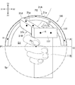
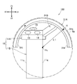
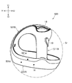
- the input device 400 will be described as another example of the input device proposed in the present disclosure with reference to FIGS. 9 to 12.
- the differences between the input device 400 and the input device 100 will be mainly described. Matters not described may be the same as the input device 100.
- the main body 410 of the input device 400 has a grip 411B and an operation unit 411A in which a plurality of operation members are arranged.
- the operation buttons 13 and 14 and the operation stick 15 are arranged on the operation unit 411A as operation members.
- the input device 400 has a rear tracked unit 431A and a front tracked unit 431B.
- a plurality of light emitting units H are provided in each of the rear tracked unit 431A and the front tracked unit 431B, and their outer surfaces form a tracked region.
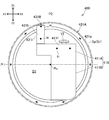
- the rear tracked portion 431A is an annular shape that surrounds the center line Pc along the front-rear direction over the entire circumference. That is, the rear tracked portion 431A is formed over 360 degrees in the circumferential direction centered on the center line Pc.
- the outer shape of the rear tracked portion 431A is curved along the perfect circle Sp centered on the center line Pc along the front-rear direction. good.
- the outer shape of the rear tracked portion 431A is curved at least partially along the perfect circle Sp in this way, the calculation process of the position and orientation of the input device 400 can be simplified.
- most of the outer shape of the rear tracked portion 431A may be curved in accordance with the perfect circle Sp.
- the entire rear tracked portion 431A is curved according to the perfect circle Sp.
- the distance L1 (see FIG. 12) between the plurality of light emitting units H provided in the rear tracked unit 431A and the center line Pc may be the same.
- a part of the rear tracked portion 431A (for example, the connection portion 431d between the rear tracked portion 431A and the front tracked portion 431B and the connection portion between the rear tracked portion 431A and the grip 411B) is located outside the perfect circle Sp. You may be doing it. Even in this case, the distance L1 (see FIG. 12) between the plurality of light emitting units H provided in the rear tracked unit 431A and the center line Pc may be the same.
- the rear tracked portion 431A may extend straight in the vertical direction in the side view of the input device 400. According to this, the shape of the rear tracked portion 431A is simplified, and the calculation process of the position and orientation of the input device 400 based on the position of the light emitting portion H can be simplified.
- the rear tracked portion 431A is tilted with respect to the grip 411B in the side view of the input device 400.
- the rear tracked portion 431A may extend straight in the left-right direction in the plan view of the input device 400. According to this, the shape of the rear tracked portion 31A becomes simple, and the calculation process of the position and orientation of the input device 400 based on the position of the light emitting portion H can be simplified.
- the outer surface of the rear-tracked portion 431A includes a front-inclined surface 431a and a rear-inclined surface 431b, as in the example of the input device 100.
- a plurality of light emitting portions H are provided on each of the front inclined surface 431a and the rear inclined surface 431b.
- the plurality of light emitting portions H are arranged in the circumferential direction on the front inclined surface 431a and the rear inclined surface 431b.
- the width Wb of the rear inclined surface 431b may be larger than the width Wa of the front inclined surface 431a.
- the front inclined surface 431a and the rear inclined surface 431b are preferably formed over the entire circumference of the rear tracked portion 431A. Unlike this, the front inclined surface 431a and the rear inclined surface 431b may be formed only on a part of the rear tracked portion 431A (for example, the upper part of the rear tracked portion 431A).
- a plurality of light emitting portions H may be provided on the left side surface 411c of the grip 411B. Further, a plurality of light emitting units H may be provided on the front surface 411f of the operation unit 411A.
- the light emitting portion H is not provided on another region on the outer surface of the main body 10, for example, the rear surface or the front surface of the grip 11B.
- the front tracked section 431B extends rearwardly and upwardly from the right side of the operation section 411A and is connected to the upper part of the rear tracked section 431A. As shown in FIG. 10, the front tracked portion 431B may extend backward and upward while curving.
- the light emitting portion H may be provided on two surfaces of the front tracked portion 431B. As a result, the detection accuracy of the light emitting unit H arranged in the front tracked unit 431B can be improved.
- the light emitting unit H may be provided on the upper surface (front surface) 431h (see FIG. 11) and the right side surface 431i (see FIG. 11) of the front tracked unit 431B.
- the lower part of the rear tracked part 431A is connected to the rearmost part (bottom part) of the grip 411B.
- the upper portion of the rear tracked portion 431A is connected to the main body 410 via the front tracked portion 431B. According to this, since the lower portion and the upper portion of the rear tracked portion 431A are supported, the rigidity of the rear tracked portion 431A can be sufficiently ensured. As a result, for example, it is possible to prevent the posture of the rear tracked portion 431A from changing with respect to the main body 10 when an unintended external force acts on the rear tracked portion 431A.
- the upper portion of the rear tracked portion 431A is a portion above the horizontal plane P1 (see FIG. 9) passing through the center of the rear tracked portion 431A in the vertical direction, and is the lower portion of the rear tracked portion 31A. Is a portion below the horizontal plane P1.
- the tracked area on the outer surface of the input device 400 has curved surfaces constituting one spherical surface Sr (same spherical surface) at at least two positions separated from each other. According to this shape, it is possible to facilitate the calculation process of the position and the posture of the input device 100 based on the position of the light emitting unit H detected by the camera.
- the tracked portions 431A and 431B and the main body 410 are located inside the spherical surface Sr.
- the input device 400 has such curved surfaces on the rear portion and the front portion of the input device 400.
- a rear inclined surface 431b of the rear tracked portion 31A is provided at the rear portion of the input device 400.
- the rear inclined surface 431b is a part of the virtual spherical surface Sr and is curved along the spherical surface Sr.
- the rear inclined surface 431b is located behind the operation members 13, 14, and 15 operated by the thumb in the plan view of the input device 400.
- the rear inclined surface 431b is an annular shape surrounding the grip 411B in the rear view of the input device 400 (see FIG. 12).
- the rear tracked portion 431A may have an arc shape.
- the rear inclined surface 431b is located at the rearmost part of the input device 100. According to such an arrangement of the rear inclined surface 431b, it becomes easy for the camera mounted on the HMD2 to capture the light from the light emitting portion H of the rear inclined surface 31b.
- a front surface 411f of the operation unit 411A is provided at the front portion of the input device 400.
- the front surface 411f of the operation unit 411A is a surface located in front of the operation members 13, 14, and 15.
- the front surface 411f of the operation unit 411A is a part of the spherical surface Sr and is curved along the spherical surface Sr.
- the front surface (upper surface) 431h of the front tracked unit 431B may also form a part of the spherical surface Sr.
- a space S1 surrounded by the main body 410 and the rear tracked portion 431A is secured below the front tracked portion 431B.
- the palm of the user is arranged in this space S1.
- the main body 410 is displaced to the left with respect to the plane P2 passing through the center of the input device 400 in the left-right direction.
- connection portion 431d between the front tracked portion 31B and the rear tracked portion 31A is located on the right side of the plane P2.
- the front tracked portion 431B is separated from the right side surface of the grip 411B to the right.
- a gap G1 is secured between the right side surface of the grip 411B and the front tracked portion 431B. This makes it possible to prevent the thumb from interfering with the connection portion 431d and the front tracked portion 431B while the user is holding the grip 11B.
- the front tracked unit 431B may extend diagonally to the right and rearward from the right side of the operation unit 411A. By doing so, the gap G1 can be made larger.
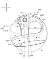
- the input device 500 will be described as another example of the input device proposed in the present disclosure with reference to FIGS. 13 to 19.
- the differences between the input device 500 and the input device (particularly, the input device 400) described so far will be mainly described.
- the matters not described may be the same as those of the input device described so far.
- the main body 510 of the input device 500 has a grip 511B and an operation unit 511A in which a plurality of operation members are arranged.
- the operation buttons 13 and 14 and the operation stick 15 are arranged on the operation unit 511A as operation members.
- the operation buttons 16 and 17 may also be arranged on the operation unit 511A.
- the input device 500 has a rear tracked unit 531A and a front tracked unit 531B.
- the rear tracked portion 531A is annular (see FIG. 16).
- the front tracked unit 531B is connected to the upper part of the main body 510 (specifically, the operation unit 511B) and the rear tracked unit 531A.
- the front tracked portion 531B extends to the right from the upper portion (operation portion 511A) of the main body 510.
- the front tracked portion 531B is higher than the position of the center line Pc (see FIG. 16) of the rear tracked portion 531A.
- a space S1 for placing four fingers except the thumb is secured under the front tracked portion 531B.
- the upper surface 531h of the front tracked portion 531B is connected to the upper surface 511b of the operation unit 511A. There is no step between them. As a result, the user can smoothly move his / her finger on the upper surface of the operation unit 511A.
- the front portion of the front tracked portion 531B and the upper surfaces 531h and 511b of the operation portion 511A may be substantially parallel to the horizontal plane P4. This also contributes to the smooth movement of the user's finger.
- the horizontal plane P4 is, for example, a plane perpendicular to the center line Pv3 of the operation stick 15.
- the straight line Pv3 may be in the pressing direction of the operation buttons 13 and 14.
- the upper surface 531h of the front tracked portion 531B extends diagonally backward and upward. As a result, the width of the front tracked portion 531B in the vertical direction increases. As a result, the connection strength between the front tracked portion 531B and the rear tracked portion 531A is increased. Further, since the height of the upper surface 531h is relatively low in the front portion of the front tracked portion 531B, there is sufficient space for the operation unit 511A to allow the movement of the thumb for operating the operation member arranged in the operation unit 511A. It can be secured between (or the front portion of the front tracked portion 531B) and the rear tracked portion 531A.
- the lower surface 531j of the front tracked portion 531B may also be substantially parallel to the horizontal plane P4. According to this, when the user presses the trigger button 18 described later with the index finger, the index finger can be smoothly moved along the lower surface 531j of the tracked portion 531A.
- the lower surface 531j of the front tracked portion 531B extends diagonally backward and downward. As a result, the width of the front tracked portion 531B in the vertical direction increases. As a result, the connection strength between the front tracked portion 531B and the rear tracked portion 531A is increased. Further, since the height of the lower surface 531j is relatively high in the front portion of the front tracked portion 531B, the movement of the index finger for operating the operation member (trigger button 18 described later) arranged on the front side of the operation portion 511A can be performed. Sufficient space to allow may be secured below the anterior portion of the anterior tracked portion 531B.
- the lower part of the rear tracked part 531A is connected to the rearmost part (bottom part) of the grip 511B. Further, as described above, the upper surface 531h of the front tracked portion 531B extends diagonally backward and upward, and the lower surface 531j of the front tracked portion 531B extends diagonally backward and downward. Therefore, the size of the connection portion between the front tracked portion 531B and the rear tracked portion 531A in the vertical direction becomes large. As a result, the rigidity of the rear tracked portion 531A can be increased. Then, for example, when an unintended external force acts on the rear tracked unit 531A, it is possible to suppress a change in the relative position between the rear tracked unit 531A and the front tracked unit 531B (or the operation unit 511A).
- the lower surface 531j of the front tracked portion 531B overlaps with the grip 511B in the side view of the input device 500.
- the back of the hand holding the grip 511B and the rear portion of the front tracked portion 531B face each other in the left-right direction. Therefore, for example, when the user temporarily releases the grip 511B, the area where the rear portion of the front tracked portion 531B touches the back of the hand increases. As a result, the relative posture between the input device 500 and the hand is easily maintained.
- the shape and arrangement of the front tracked portion 531B is not limited to the example of the input device 500.
- the front tracked portion 531B may extend diagonally backward and upward from the operating portion 511A.
- the upper surface 531h of the front tracked portion 531B and the upper surface 511b of the operation portion 511A may also be inclined.
- the rear tracked portion 531A is an annular shape that opens toward the rear side.
- the rear tracked portion 531A is an annular shape that surrounds the center line Pc2 over the entire circumference. That is, the rear tracked portion 531A is formed over 360 degrees in the circumferential direction centered on the center line Pc2.
- the center line Pc2 is a line extending diagonally backward. More specifically, as shown in FIG. 13, the center line Pc2 is inclined with respect to the vertical plane P5 in the plan view of the input device 500.
- the vertical plane P5 may be a plane substantially along the grip 511B. Further, the vertical plane P5 may include the center line Pv3 of the operation stick 15.
- the center of the rear tracked portion 531A is offset / positioned on the side where the range of motion in the left-right bending motion of the wrist is wide with respect to the grip 511B.
- the area of the opening of the annular rear tracked portion 531A becomes large on the side where the range of motion of the wrist is large with respect to the grip 511B. According to this relative position of the grip 511B and the rear tracked portion 531A, it is possible to prevent the user's wrist or arm from interfering with the rear tracked portion 531A when the user is holding the grip 511B, and comfortable operation is possible. Can be realized.
- the grip 511B is displaced to the left with respect to the vertical plane P2 passing through the center of the input device 500 in the left-right direction.
- the center line Pc2 of the rear tracked portion 531A is a straight line extending diagonally backward and to the right.
- the grip 511B is offset / positioned to the side where the range of motion in the left-right bending motion of the wrist is narrow, and the grip 511B is used.
- the center of the rear tracked portion 531A is offset / positioned on the side where the range of motion in the bending motion in the left-right direction of the wrist is wide.
- the area of the opening of the annular rear tracked portion 531A becomes larger on the side where the range of motion of the wrist is larger than that of the grip 511B. According to this inclination of the rear tracked portion 531A, it is possible to prevent the user's wrist or arm from interfering with the rear tracked portion 531A when the user is holding the grip 511B with the right hand, and comfortable operation is realized. obtain.
- the input device 500 may be for the left hand.
- the grip 511B is displaced to the right with respect to the plane P2 passing through the center of the input device 500 in the left-right direction.
- the center line Pc2 of the rear tracked portion 531A is a straight line extending diagonally backward and to the left.
- the center line Pc2 of the rear tracked portion 531A may be inclined with respect to the horizontal plane P4. More specifically, the center line Pc2 may extend diagonally backward and upward with respect to the horizontal plane P4.
- the center of the rear tracked portion 531A is offset / positioned on the side where the range of motion in the vertical bending motion of the wrist is wide with respect to the grip 511B. That is, the area of the annular opening is large on the side where the range of motion of the wrist is large with respect to the grip 511B.
- the horizontal plane P4 may be a plane substantially orthogonal to the center line Pv3 of the operation stick 15.
- the rear tracked portion 531A does not have to be formed over 360 degrees in the circumferential direction centered on the center line Pc2.
- the rear tracked portion 531A may have an arc shape that covers only the upper side of the grip 511B in the rear view of the input device 500.
- the center line Pc2 of the rear tracked portion 531A may be inclined with respect to the horizontal plane P4 and / or the vertical plane P5, similarly to the input device 500.
- a plurality of light emitting units H arranged in the left-right direction are provided on the front surface 511f of the operation unit 511A and the front surface (side surface) 531i of the front tracked unit 531B.
- two light emitting units H are provided on the front surface 511f of the operation unit 511A, and one light emitting unit H is provided on the front tracked unit 531B.
- the number of light emitting units H provided in the front tracked unit 531B may be two or more.
- the light emitting portions H provided on the front surface 511f / 531i may be arranged along the horizontal plane P4. Unlike this, the direction in which the light emitting portions H are lined up may be inclined with respect to the horizontal plane P4.
- the light emitting unit H may not be provided in the front tracked unit 531B.
- the front tracked portion 531B does not function as a tracked track, but can function as a beam portion that connects the operation section 511A and the rear tracked section 531A and secures the strength of the rear tracked section 531A.
- the outer surface of the rear-tracked portion 531A includes a front-tilted surface 531a and a rear-tilted surface 531b, similarly to the rear-tracked portion 431A of the input device 400.
- a plurality of light emitting portions H are provided on each of the front inclined surface 531a and the rear inclined surface 531b.
- the plurality of light emitting portions H are arranged along the extending direction (circumferential direction centered on the center line Pc2) of the rear tracked portion 531A. Similar to the rear tracked portion 431A of the input device 400, the width of the rear inclined surface 531b (Wb in FIG. 5) may be larger than the width of the front inclined surface 531a (Wa in FIG. 5).
- the position of the light emitting portion H provided on the front inclined surface 531a and the position of the light emitting portion H provided on the rear inclined portion 531b are in the extending direction of the rear tracked portion 531A (circumferential direction centered on the center line Pc2). ) May be off. According to this, the distance between the light emitting units H is increased, and the positions of the two adjacent light emitting units H can be easily identified. As a result, the accuracy of detecting the position and orientation of the input device 500 by the camera mounted on the HMD2 (see FIG. 1) can be improved.
- the tracked area on the outer surface of the input device 500 includes a curved surface forming one spherical surface Sr (same spherical surface) in front of the operating member (operation stick 15 and the like) and behind the operating member (operation stick 15 and the like).
- the rear inclined surface 531b located at the rear of the input device 500 is a part of the virtual spherical surface Sr and is curved along the spherical surface Sr.
- the front surface 511f of the operation unit 511A is also a part of the spherical surface Sr and is curved along the spherical surface Sr. Further, as shown in FIG.
- the front surface 531i of the front tracked portion 531B also constitutes a part of the spherical surface Sr. According to this shape, it is possible to facilitate the calculation process of the position and the posture of the input device 500 based on the position of the light emitting unit H detected by the camera mounted on the HMD 2.
- the plurality of light emitting portions H are provided on the rear inclined surface 531b of the rear tracked portion 531A, the front tracked portion 531B, and the front surface 531i / 511f of the main body 510.
- These surfaces 531b, 531i, and 511f are curved surfaces that form a part of the spherical surface Sr. Therefore, the plurality of light emitting units H arranged on the rear inclined surface 531b and the plurality of light emitting units H arranged on the front surface 531i / 511f are located on one virtual spherical surface Sr.
- the light emitting unit H it is possible to facilitate the calculation process of the position and the posture of the input device 500 based on the position of the light emitting unit H detected by the camera mounted on the HMD 2.
- the grip 511B and the operating member are arranged inside the virtual spherical surface Sr. Therefore, when the user holds the grip 511B and uses the input device, the user's hand does not block the light emitting unit H. Further, since the light emitting unit H is located on the virtual spherical surface Sr in which the user's hand is arranged inside, the calculation process of the hand position can be facilitated.
- one or both of the rear inclined surface 531b of the rear tracked portion 531A, the front tracked portion 531B, and the front surface 531i / 511f of the main body 510 may not be curved surfaces.
- the front surface 531i / 511f may be a plane extending diagonally upward and backward.
- the rear inclined surface 531b may be a plane extending diagonally rearward toward the center line Pc2.
- the plurality of light emitting units H located in front of the operating member (operation stick 15, etc.) and the plurality of light emitting units H located behind the operating member may be located on one spherical surface Sr.
- the plurality of light emitting units H arranged on the rear inclined surface 531b and the plurality of light emitting units H arranged on the front surface 531h / 511f may be located on one virtual spherical surface Sr. By doing so, it is possible to facilitate the calculation process of the position and posture of the input device 500 based on the position of the light emitting unit H detected by the camera mounted on the HMD 2.
- the front inclined surface 531a of the front tracked portion 531B is a surface extending diagonally rearward toward the center line Pc2. As shown in FIG. 14, the front surface of the front tracked portion 531B extends rearward while curving, and is connected to the rear inclined portion 531b on the right side of the rear tracked portion 531A. Therefore, the front inclined surface 531a is not formed on the right side of the rear tracked portion 531A.
- the light emitting unit H is not provided other than the rear tracked unit 531A, the front tracked unit 531B, and the front surface 531h / 511f of the main body 510.
- the light emitting portion H may be provided on the left side surface 511c (see FIG. 15) of the grip 511B.
- the light emitting unit H may be provided on the upper surface 531h and the front surface (side surface) 531i of the front tracked unit 531B. By doing so, the detection accuracy of the light emitting unit H arranged in the front tracked unit 531B can be further improved.
- the input device 500 has operation buttons 13, 14, 16, 17 and an operation stick 15 as its operation members (see FIG. 13).
- the operation buttons 13 and 14 are buttons for selecting and operating a game character or object, for example.
- the operation button 16 is a function button for sharing the game play, captures the game screen while the game is in progress, or captures the still image while playing the moving image, and is connected to the HMD2 or the HMD2. It is a button to save the captured image on the server device.
- the operation button 17 is, for example, a button for displaying various functions that can be selected by the user. For example, by operating the operation button 17, it is possible to select a game application to be played by the user from among a plurality of game applications in progress.
- the operation buttons 13 and 14 and the operation buttons 16 may be arranged on opposite sides of each other with the operation stick 15 interposed therebetween.
- the operation buttons 13 and 14 may be arranged on the left side of the operation stick 15, and the operation buttons 16 may be arranged on the right side of the operation stick 15. According to this arrangement, the user can set the initial position of the thumb as the operation stick 15 and smoothly move the operation buttons 13 and 14 and the operation buttons 16 from the operation stick 15 as needed.
- the operation button 17 may be arranged behind the operation stick 15.
- the operation buttons 13, 14, 16, and 17 provided on the upper surface 511b of the operation unit 511A are buttons for operating with the thumb. These are arranged in the circumferential direction centered on the operation stick 15. Therefore, the user can set the initial position of the thumb as the operation stick 15 and smoothly move the thumb to any of the operation buttons 13, 14, 16, and 17 from the operation stick 15 as needed.
- the trigger button 18 may be arranged below the front surface 511f of the operation unit 511A.
- the main body 510 may have a drive device for moving the trigger button 18.
- the drive device for example, produces a reaction force against the movement of the trigger button 18 when the trigger button 18 is pressed.
- the drive device may include, for example, an electric motor as its drive source.
- the main body 510 may have an operation button 19 on the grip 511B.
- the operation button 19 may be provided on the side surface of the grip 511B.
- the input device 500 is a device for the right hand, and the operation button 19 may be provided on, for example, the left side surface 511c of the grip 511B. According to this arrangement of the operation buttons 19, the user can operate the operation buttons 19 with the middle finger.
- One or more of the operation buttons 13, 14, 16 to 18 described so far may have a touch sense function for detecting the contact or proximity of the user's finger to the button surface.
- the operation stick 15 may also have a touch sense function for detecting contact or proximity of the user's finger to the upper surface of the operation stick 15.
- the main body 10, 110, 310, 410, and 510 are the grips 11B, 311B, 411B, and 511B, and at least one operation member operated by the user's finger. It has 13 to 19.
- the input devices 100, 300, 400, and 500 are located behind at least one operating member, and form a part of the tracked area. Includes front tracked portions 31B, 331B, 431B, and 531A that are located in and extend in a direction different from that of the rear tracked portion.
- the input devices 100, 300, 400, and 500 have two tracked portions having different extending directions, it is possible to improve the detection stability of the light emitting portion H by the camera mounted on the HMD2.
- the front tracked portion 31B, 331B, 431B, 531B extends from one of the upper portion of the main body and the rear tracked portion 31A, 331A, 431A, 531A toward the other. According to this, even when the user releases the grip, the front tracked portions 31B, 331B, 431B, and 531B can be caught in the hand and the input device can be suppressed from falling.
- the front tracked section 31B, 331B, 431B, 531B connects the upper part of the main body 10, 110, 310, 410, 510 to the rear tracked section 31A, 331A, 431A, 531A. According to this, the rigidity of the input device can be increased, and the change in the relative position between the rear tracked portion 331A and the main body 10, 110, 310, 410, 510 can be suppressed.
- the front tracked portions 31B, 331B, 431B, and 531B have a shape that is located between the user's thumb and the edge of the palm when the user opens the hand holding the grip.
- the front tracked portions 31B, 331B, 431B, 531B are located on the right side of the upper part of the main body 10, 110, 310, 410, 510, and the rear tracked portions 31A, 331A, are located from the upper part of the main body. It extends toward 431A and 531A.
- the main body 10, 110, 310, 410, 510 is displaced toward the left side with respect to the plane P2 passing through the center in the left-right direction of the input device, and the front tracked portion 31B, 331B, 431B. 531A is displaced toward the right side with respect to the plane P2. According to this, it becomes easy to hold and operate the main body with the right hand, and it is possible to prevent the front tracked portion from hindering the movement of the thumb.
- the front tracked portion 31B, 331B, 431B, 531B extends rearward from the upper part of the main body toward the right side, and is connected to the rear tracked portion 31A, 331A, 431A, 531A on the right side of the plane P2. According to this structure, it becomes easy to secure a space that allows the movement of the finger.
- connection portion between the front tracked portion 31B, 331B, 431B, 531B and the rear tracked portion 31A, 331A, 431A, 531A is separated from the grip to the right. According to this, a gap G1 is secured between the right side surface of the grip and the front tracked portion. This makes it possible to prevent the thumb from interfering with the connection portion between the front tracked portion and the rear tracked portion and the front tracked portion.
- the main body 10, 110, 310, 410, 510 is displaced toward the left side with respect to the plane P2 passing through the center in the left-right direction of the input device, and the front tracked portion 31B, 331B, 431B.
- the 531B extends from the upper portion of the main body 10, 110, 310, 410, 510 toward the right side in the front view of the input device.
- the rear tracked portions 31A, 431A, and 531A include at least an arc-shaped upper portion that surrounds the upper side of the grip in the rear view of the input device. According to this, since the light emitting unit H is less likely to be hidden from the camera mounted on the HMD2 by the rear tracked units 31A, 431A, and 531A, the posture and position detection accuracy of the input device can be improved.
- the rear tracked portions 331A, 431A, and 531A are annular in the rear view of the input device. According to this, for example, even when the posture of the input device is inverted in the vertical direction, the detection accuracy of the posture and position of the input device can be ensured.
- the rear tracked portion 531A is an annular shape surrounding the center line Pc2 extending diagonally backward. According to this, it is possible to suppress the interference between the user's wrist and the rear tracked portion.
- the rear tracked portion 531A may have an arc shape surrounding the center line Pc2 extending diagonally rearward.
- the rear tracked portions 431A and 531A are substantially perfect circles. According to this, it is possible to facilitate the calculation process of the position and the posture of the input device based on the position of the light emitting unit H detected by the camera.
- the rear tracked portions 431A and 531A are connected to the lower part of the grip.
- the connection portion between the rear tracked portions 431A and 531A and the grip is unlikely to interfere with the use of the input device.
- the rear tracked portions 31A, 331A, 431A, and 531A are located behind the front part of the grip in the side view of the input device.
- the rear tracked portion 531A is an annular shape that surrounds the center line Pc2 that extends diagonally backward and upward in the side view of the input device. According to this, it is possible to suppress the interference between the user's wrist and the rear tracked portion.
- the rear tracked portion 531A may have an arc shape surrounding the center line Pc2.
- the grip is offset to the left with respect to the center of the input device in the left-right direction.
- the rear tracked portion 531A is an annular shape that surrounds the center line Pc2 extending diagonally rearward and to the right in the plan view of the input device. According to this, it is possible to suppress the interference between the user's wrist and the rear tracked portion.
- the rear tracked portion 531A may have an arc shape surrounding the center line Pc2.
- the tracked areas are the rear inclined surfaces 431b / 531b formed at the rear of the rear input devices 400/500 and the front surface 411f / 511f formed at the front of the input devices 400/500. -Has 531i.
- the rear inclined surfaces 431b / 531b and the front surface 411f / 511f / 531i are a part of one spherical surface Sr. It is possible to facilitate the calculation process of the position and posture of the input devices 400/500 based on the position of the light emitting unit H detected by the camera.
- the rear inclined surfaces 431b / 531b are located behind at least one operating member (for example, the operating stick 15), and the front surface 411f / 511f / 531i is located at least one operating member (for example, for example). It is located in front of the operation stick 15). According to this, it is possible to reduce the restrictions on the postures of the input devices 400 and 500 required for ensuring the detection stability of the light emitting unit H.
- the rear inclined surfaces 431b and 531b are arcuate or annular at least surrounding the upper side of the grips 411B and 511B. Since the light emitting unit H is less likely to be hidden from the camera mounted on the HMD2 by the rear tracked units 431A and 531A, the accuracy of detecting the posture and position of the input device can be improved.
- the tracked region has a rear inclined surface 431b, 531b in which a plurality of light emitting portions H are arranged, and a front surface 411f, 511f, 531i in which a plurality of light emitting portions H are arranged. ..
- the plurality of light emitting units H arranged on the rear inclined surfaces 431b and 531b and the plurality of light emitting units H arranged on the front surface 411f, 511f, and 531i are located on one virtual spherical surface Sr. It is possible to facilitate the calculation process of the position and posture of the input devices 400/500 based on the position of the light emitting unit H detected by the camera.
- the plurality of light emitting units H arranged side by side on the rear inclined surfaces 431b and 531b are located behind at least one operating member (for example, the operating stick 15) and are located on the front surface 411f, 511f, 531i.
- the plurality of light emitting units H arranged side by side are located in front of at least one operating member (for example, the operating stick 15). According to this, it is possible to reduce the restrictions on the postures of the input devices 400 and 500 required for ensuring the detection stability of the light emitting unit H.
- the input devices 400 and 500 at least a part of the plurality of light emitting portions H arranged on the rear inclined surfaces 431b and 531b is provided on the surface facing the rear side and the upper side of the input device. Further, the front surfaces 411f, 511f, and 531i provided with the plurality of light emitting units H face the front side of the input devices 400 and 500. According to this, it is possible to reduce the restrictions on the postures of the input devices 400 and 500 required for ensuring the detection stability of the light emitting unit H.
- the input devices 100, 300, 400, and 500 include main bodies 10, 110, 310, 410, and 510 having a grip and at least one operating member (for example, an operating stick 15) operated by a user's finger. Have. Further, the input devices 100, 300, 400, and 500 are located behind at least one operating member and have rear tracked portions 31A, 331A, 431A, and 531A that cover at least the upper side of the grip in rear view. Further, the input devices 100, 300, 400, and 500 have a beam portion connected to the upper portion of the main body 10, 110, 310, 410, 510 and the rear tracked portions 31A, 331A, 431A, and 531A. There is.
- the "beam portion” is the front tracked portion 31B, 331B, 431B, 531B.
- the rear tracked portion and the main body 10, 110, 310, 410, 510 are provided in the rear tracked portion. It is possible to suppress a change in the relative position between the light emitting unit H provided on the light emitting unit H and the light emitting unit H provided on the main body, and it is possible to improve the calculation accuracy of the position and posture of the input device.
- the front tracked units 31B, 331B, 431B, and 531B are not necessarily the main body 10, 110, 310, 410, 510 and the rear tracked units 31A, 331A, 431A. It does not have to be connected to both of the 531A. That is, the front tracked unit 31B, 331B, 431B, 531B may be connected to only one of the main body 10, 110, 310, 410, 510 and the rear tracked unit 31A, 331A, 431A, 531A. Even in this case, when the user opens the hand holding the grip 11B, the front tracked portion 31B is located between the user's thumb and the base of the index finger (the end of the fingertip ball). By doing so, it is possible to prevent the input device 100 from falling from the hand when the user spreads his / her hand.
- FIGS. 19 to 23 are diagrams showing another example of the input device proposed in the present disclosure.
- the input device 200 for the right hand will be described in detail.
- the outer shape of the input device 200 for the right hand and the outer shape of the input device 200 for the left hand are symmetrical.
- the number and types of operating members arranged in the operating unit 211A, which will be described later, may differ between the left and right input devices 200. Further, regarding the arrangement of the operating members, the input device 200 for the right hand and the input device 200 for the left hand do not have to be symmetrical.
- the input device 200 has a main body 210 having a grip 211B and an operation unit 211A in which a plurality of operation members are arranged.
- the main body 210 has an operation portion 211A in the upper portion thereof, and the grip 211B is formed below the operation portion 211A.
- the operation member arranged in the operation unit 211A can be operated by the thumb or the index finger while holding the grip 211B.
- the operation member for example, the operation buttons 213 and 214 and the operation stick 215 are arranged on the operation unit 211A.
- the operation button 213 is arranged on the front surface 211a of the operation unit 211A, and is operated by, for example, a human pointing finger.
- the operation button 214 and the operation stick 215 are arranged on the upper surface of the operation unit 211A and are operated by, for example, the thumb.
- a plurality of operation buttons 216 are arranged on the grip 211B.
- the input device 200 has a tracked area in which a plurality of light emitting units H are arranged.
- the tracked region is composed of an outer surface of the rear curved portion 231A and an outer surface of the front connecting portion 231B (see FIG. 23).
- the rear curved portion 231A has an inner wall portion 231a and an outer wall portion 231c.
- the inner wall portion 231a extends rearward from the main body 210.
- the outer wall portion 231c is separated from the inner wall portion 231a to the right.
- the user can put his right hand between the inner wall portion 231a and the outer wall portion 231c to grip the grip 211B.
- the inner wall portion 231a is located inside the hand and the outer wall portion 231c is located outside the hand.
- the rear connecting portion 231b is located on the rear side of the inner wall portion 231a and the outer wall portion 231c, and connects the upper portions thereof.
- the rear curved portion 231A has a substantially U-shape that opens downward in the rear view of the input device 200.
- the rear curved portion 231A surrounds the upper side of the user's wrist.
- a plurality of light emitting portions H are arranged in each of the inner wall portion 231a, the outer wall portion 231c, and the rear connecting portion 231b.
- the detection stability of the light emitting portion H by the camera mounted on the HMD2 can be improved. ..
- the front connecting portion 231B is located in front of the rear bending portion 231A.
- the rear connecting portion 231b extends in the left-right direction on the upper side of the user's wrist.
- the outer wall portion 231c extends forward while curving from the rear connecting portion 231b.
- the front connecting portion 231B is further curved and extends diagonally forward and to the left.
- the inner wall portion 231a, the outer wall portion 231c, the rear connecting portion 231b, and the front connecting portion 231B extend in different directions, and have an elongated elliptical shape in the front-rear direction in a plan view.
- the front connecting portion 231B is located between the upper portion of the outer wall portion 231c and the upper portion of the main body 210 (operation portion 211A), and connects them.
- the front connecting portion 231B is located on the right side of the upper part of the main body 210 (see FIG. 23), extends rearward while curving from the upper part of the main body 210, and is connected to the upper part of the outer wall portion 231c.
- the anterior connecting portion 231B is located between the user's thumb and the base of the index finger (the end of the fingertip) when the user opens the hand holding the grip 211B. .. Therefore, it is possible to prevent the input device 100 from falling from the hand when the user spreads his / her hand.
- the main body 210 is displaced to the left with respect to the plane P3 passing through the center of the input device 200 in the left-right direction.
- the front connecting portion 231B is displaced to the right with respect to the same plane P3. According to this arrangement, it becomes easy to hold and operate the main body 210 with the right hand.
Landscapes
- Engineering & Computer Science (AREA)
- General Engineering & Computer Science (AREA)
- Theoretical Computer Science (AREA)
- Human Computer Interaction (AREA)
- Physics & Mathematics (AREA)
- General Physics & Mathematics (AREA)
- Multimedia (AREA)
- Position Input By Displaying (AREA)
- Image Input (AREA)
- User Interface Of Digital Computer (AREA)
- Push-Button Switches (AREA)
- Eye Examination Apparatus (AREA)
- Photometry And Measurement Of Optical Pulse Characteristics (AREA)
- Facsimile Scanning Arrangements (AREA)
Priority Applications (10)
| Application Number | Priority Date | Filing Date | Title |
|---|---|---|---|
| JP2022527523A JP7401671B2 (ja) | 2020-05-29 | 2021-02-26 | 入力デバイス |
| BR112022023836A BR112022023836A2 (pt) | 2020-05-29 | 2021-02-26 | Dispositivo de entrada |
| AU2021280384A AU2021280384B2 (en) | 2020-05-29 | 2021-02-26 | Input device |
| KR1020227045615A KR102705948B1 (ko) | 2020-05-29 | 2021-02-26 | 입력 장치 |
| US17/998,697 US20230191243A1 (en) | 2020-05-29 | 2021-02-26 | Input device |
| CA3178888A CA3178888A1 (en) | 2020-05-29 | 2021-02-26 | Input device |
| EP21812625.8A EP4160309A4 (en) | 2020-05-29 | 2021-02-26 | INPUT DEVICE |
| CN202180028031.6A CN115398381B (zh) | 2020-05-29 | 2021-02-26 | 输入设备 |
| MX2022014841A MX2022014841A (es) | 2020-05-29 | 2021-02-26 | Dispositivo de entrada. |
| JP2023207209A JP7704824B2 (ja) | 2020-05-29 | 2023-12-07 | 入力デバイス |
Applications Claiming Priority (2)
| Application Number | Priority Date | Filing Date | Title |
|---|---|---|---|
| JP2020-094853 | 2020-05-29 | ||
| JP2020094853 | 2020-05-29 |
Publications (1)
| Publication Number | Publication Date |
|---|---|
| WO2021240930A1 true WO2021240930A1 (ja) | 2021-12-02 |
Family
ID=78744243
Family Applications (1)
| Application Number | Title | Priority Date | Filing Date |
|---|---|---|---|
| PCT/JP2021/007459 Ceased WO2021240930A1 (ja) | 2020-05-29 | 2021-02-26 | 入力デバイス |
Country Status (10)
| Country | Link |
|---|---|
| US (1) | US20230191243A1 (https=) |
| EP (1) | EP4160309A4 (https=) |
| JP (2) | JP7401671B2 (https=) |
| KR (1) | KR102705948B1 (https=) |
| CN (1) | CN115398381B (https=) |
| AU (1) | AU2021280384B2 (https=) |
| BR (1) | BR112022023836A2 (https=) |
| CA (1) | CA3178888A1 (https=) |
| MX (1) | MX2022014841A (https=) |
| WO (1) | WO2021240930A1 (https=) |
Cited By (7)
| Publication number | Priority date | Publication date | Assignee | Title |
|---|---|---|---|---|
| WO2023189848A1 (ja) | 2022-03-30 | 2023-10-05 | 株式会社ソニー・インタラクティブエンタテインメント | 入力デバイス、入力デバイスのアクセサリ部品、及びそれらを含む入力デバイス組立体 |
| EP4356992A1 (en) | 2022-10-18 | 2024-04-24 | Sony Interactive Entertainment Inc. | Cradle and system including cradle and input device |
| WO2024190134A1 (ja) * | 2023-03-16 | 2024-09-19 | ソニーグループ株式会社 | 情報処理装置、情報処理方法および非一時的記憶媒体 |
| US12314487B2 (en) | 2022-02-18 | 2025-05-27 | Sony Interactive Entertainment Inc. | Information processing apparatus, device speed estimation method, and device position estimation method |
| US12314486B1 (en) | 2022-02-18 | 2025-05-27 | Sony Interactive Entertainment Inc. | Information processing apparatus and device position estimation method |
| US12353648B2 (en) | 2022-02-18 | 2025-07-08 | Sony Interactive Entertainment Inc. | Information processing apparatus and device position estimation method |
| US12429959B2 (en) | 2023-01-27 | 2025-09-30 | Sony Interactive Entertainment Inc. | Information processing apparatus and device position acquisition method |
Families Citing this family (1)
| Publication number | Priority date | Publication date | Assignee | Title |
|---|---|---|---|---|
| US20230409113A1 (en) * | 2022-06-16 | 2023-12-21 | Neil Nelson | Extended reality interface |
Citations (4)
| Publication number | Priority date | Publication date | Assignee | Title |
|---|---|---|---|---|
| JP2011164932A (ja) | 2010-02-09 | 2011-08-25 | Sony Computer Entertainment Inc | 操作デバイス |
| US20160364910A1 (en) * | 2015-06-11 | 2016-12-15 | Oculus Vr, Llc | Hand-Held Controllers with Light-Emitting Diodes Synchronized to an External Camera |
| JP2017099608A (ja) * | 2015-12-01 | 2017-06-08 | 株式会社コロプラ | 制御システム及びプログラム |
| WO2019181118A1 (ja) * | 2018-03-23 | 2019-09-26 | 株式会社ワコム | 3次元位置指示器及び3次元位置検出システム |
Family Cites Families (20)
| Publication number | Priority date | Publication date | Assignee | Title |
|---|---|---|---|---|
| WO2007005932A2 (en) | 2005-07-01 | 2007-01-11 | Hillcrest Laboratories, Inc. | 3d pointing devices |
| WO2014115541A1 (ja) | 2013-01-22 | 2014-07-31 | 株式会社ラパンクリエイト | コントローラおよび発光装置 |
| US9833700B2 (en) * | 2015-06-11 | 2017-12-05 | Oculus Vr, Llc | Connectable hand-held controllers for virtual-reality systems |
| CN106648043A (zh) * | 2015-11-02 | 2017-05-10 | 广东虚拟现实科技有限公司 | 用于控制器的信号采集方法及控制器 |
| US10007339B2 (en) * | 2015-11-05 | 2018-06-26 | Oculus Vr, Llc | Controllers with asymmetric tracking patterns |
| US10130875B2 (en) * | 2015-11-12 | 2018-11-20 | Oculus Vr, Llc | Handheld controller with finger grip detection |
| US9804693B2 (en) * | 2015-12-18 | 2017-10-31 | Oculus Vr, Llc | Handheld controller with activation sensors |
| CN205899500U (zh) | 2016-07-27 | 2017-01-18 | 上海拆名晃信息科技有限公司 | 用于实现人机交互的手柄 |
| KR20210104012A (ko) * | 2016-08-24 | 2021-08-24 | 디스이즈엔지니어링 주식회사 | 드론 컨트롤러 |
| US10987573B2 (en) * | 2016-10-11 | 2021-04-27 | Valve Corporation | Virtual reality hand gesture generation |
| US10888773B2 (en) * | 2016-10-11 | 2021-01-12 | Valve Corporation | Force sensing resistor (FSR) with polyimide substrate, systems, and methods thereof |
| US10307669B2 (en) * | 2016-10-11 | 2019-06-04 | Valve Corporation | Electronic controller with finger sensing and an adjustable hand retainer |
| US10537795B2 (en) * | 2017-04-26 | 2020-01-21 | Facebook Technologies, Llc | Hand-held controller using LED tracking ring |
| US10503247B2 (en) * | 2017-05-09 | 2019-12-10 | Microsoft Technology Licensing, Llc | Calibration of stereo cameras and handheld object |
| WO2019033322A1 (zh) * | 2017-08-16 | 2019-02-21 | 广东虚拟现实科技有限公司 | 手持式控制器、跟踪定位方法以及系统 |
| US10409392B1 (en) * | 2017-10-11 | 2019-09-10 | Facebook Technologies, Llc | Hand-held controller tracked by LED mounted under a concaved dome |
| JP7353773B2 (ja) * | 2019-03-18 | 2023-10-02 | 株式会社ソニー・インタラクティブエンタテインメント | 複数のマーカを備えたデバイス |
| JP7163352B2 (ja) * | 2020-11-06 | 2022-10-31 | 株式会社ソニー・インタラクティブエンタテインメント | 入力デバイス |
| US12059609B2 (en) * | 2022-06-10 | 2024-08-13 | Sony Interactive Entertainment Inc. | Asynchronous dynamic vision sensor LED AI tracking system and method |
| US11995226B2 (en) * | 2022-06-10 | 2024-05-28 | Sony Interactive Entertainment Inc. | Dynamic vision sensor tracking based on light source occlusion |
-
2021
- 2021-02-26 AU AU2021280384A patent/AU2021280384B2/en active Active
- 2021-02-26 KR KR1020227045615A patent/KR102705948B1/ko active Active
- 2021-02-26 WO PCT/JP2021/007459 patent/WO2021240930A1/ja not_active Ceased
- 2021-02-26 CA CA3178888A patent/CA3178888A1/en active Pending
- 2021-02-26 US US17/998,697 patent/US20230191243A1/en active Pending
- 2021-02-26 JP JP2022527523A patent/JP7401671B2/ja active Active
- 2021-02-26 CN CN202180028031.6A patent/CN115398381B/zh active Active
- 2021-02-26 BR BR112022023836A patent/BR112022023836A2/pt unknown
- 2021-02-26 MX MX2022014841A patent/MX2022014841A/es unknown
- 2021-02-26 EP EP21812625.8A patent/EP4160309A4/en active Pending
-
2023
- 2023-12-07 JP JP2023207209A patent/JP7704824B2/ja active Active
Patent Citations (4)
| Publication number | Priority date | Publication date | Assignee | Title |
|---|---|---|---|---|
| JP2011164932A (ja) | 2010-02-09 | 2011-08-25 | Sony Computer Entertainment Inc | 操作デバイス |
| US20160364910A1 (en) * | 2015-06-11 | 2016-12-15 | Oculus Vr, Llc | Hand-Held Controllers with Light-Emitting Diodes Synchronized to an External Camera |
| JP2017099608A (ja) * | 2015-12-01 | 2017-06-08 | 株式会社コロプラ | 制御システム及びプログラム |
| WO2019181118A1 (ja) * | 2018-03-23 | 2019-09-26 | 株式会社ワコム | 3次元位置指示器及び3次元位置検出システム |
Non-Patent Citations (1)
| Title |
|---|
| See also references of EP4160309A4 |
Cited By (7)
| Publication number | Priority date | Publication date | Assignee | Title |
|---|---|---|---|---|
| US12314487B2 (en) | 2022-02-18 | 2025-05-27 | Sony Interactive Entertainment Inc. | Information processing apparatus, device speed estimation method, and device position estimation method |
| US12314486B1 (en) | 2022-02-18 | 2025-05-27 | Sony Interactive Entertainment Inc. | Information processing apparatus and device position estimation method |
| US12353648B2 (en) | 2022-02-18 | 2025-07-08 | Sony Interactive Entertainment Inc. | Information processing apparatus and device position estimation method |
| WO2023189848A1 (ja) | 2022-03-30 | 2023-10-05 | 株式会社ソニー・インタラクティブエンタテインメント | 入力デバイス、入力デバイスのアクセサリ部品、及びそれらを含む入力デバイス組立体 |
| EP4356992A1 (en) | 2022-10-18 | 2024-04-24 | Sony Interactive Entertainment Inc. | Cradle and system including cradle and input device |
| US12429959B2 (en) | 2023-01-27 | 2025-09-30 | Sony Interactive Entertainment Inc. | Information processing apparatus and device position acquisition method |
| WO2024190134A1 (ja) * | 2023-03-16 | 2024-09-19 | ソニーグループ株式会社 | 情報処理装置、情報処理方法および非一時的記憶媒体 |
Also Published As
| Publication number | Publication date |
|---|---|
| EP4160309A1 (en) | 2023-04-05 |
| JP7401671B2 (ja) | 2023-12-19 |
| AU2021280384A1 (en) | 2023-01-05 |
| US20230191243A1 (en) | 2023-06-22 |
| CN115398381B (zh) | 2026-04-21 |
| JP7704824B2 (ja) | 2025-07-08 |
| JP2024015285A (ja) | 2024-02-01 |
| AU2021280384B2 (en) | 2024-10-10 |
| CN115398381A (zh) | 2022-11-25 |
| JPWO2021240930A1 (https=) | 2021-12-02 |
| BR112022023836A2 (pt) | 2022-12-20 |
| EP4160309A4 (en) | 2024-05-22 |
| CA3178888A1 (en) | 2021-12-02 |
| KR102705948B1 (ko) | 2024-09-11 |
| KR20230022886A (ko) | 2023-02-16 |
| MX2022014841A (es) | 2023-01-24 |
Similar Documents
| Publication | Publication Date | Title |
|---|---|---|
| JP7704824B2 (ja) | 入力デバイス | |
| JP7271245B2 (ja) | 入力デバイス | |
| US7927216B2 (en) | Video game system with wireless modular handheld controller | |
| ES2401959T5 (es) | Dispositivo de accionamiento de juegos | |
| US8313379B2 (en) | Video game system with wireless modular handheld controller | |
| JP7568799B2 (ja) | 入力デバイス | |
| JP7311550B2 (ja) | 入力デバイス | |
| JP7323566B2 (ja) | 入力デバイス | |
| JP7657949B2 (ja) | 入力デバイス | |
| JP7595779B2 (ja) | 入力デバイス |
Legal Events
| Date | Code | Title | Description |
|---|---|---|---|
| 121 | Ep: the epo has been informed by wipo that ep was designated in this application |
Ref document number: 21812625 Country of ref document: EP Kind code of ref document: A1 |
|
| ENP | Entry into the national phase |
Ref document number: 3178888 Country of ref document: CA |
|
| ENP | Entry into the national phase |
Ref document number: 2022527523 Country of ref document: JP Kind code of ref document: A |
|
| REG | Reference to national code |
Ref country code: BR Ref legal event code: B01A Ref document number: 112022023836 Country of ref document: BR |
|
| WWE | Wipo information: entry into national phase |
Ref document number: 202217070780 Country of ref document: IN |
|
| ENP | Entry into the national phase |
Ref document number: 112022023836 Country of ref document: BR Kind code of ref document: A2 Effective date: 20221123 |
|
| ENP | Entry into the national phase |
Ref document number: 20227045615 Country of ref document: KR Kind code of ref document: A |
|
| NENP | Non-entry into the national phase |
Ref country code: DE |
|
| ENP | Entry into the national phase |
Ref document number: 2021280384 Country of ref document: AU Date of ref document: 20210226 Kind code of ref document: A |
|
| ENP | Entry into the national phase |
Ref document number: 2021812625 Country of ref document: EP Effective date: 20230102 |