WO2021235218A1 - 構造体及び立体感演出方法 - Google Patents
構造体及び立体感演出方法 Download PDFInfo
- Publication number
- WO2021235218A1 WO2021235218A1 PCT/JP2021/017275 JP2021017275W WO2021235218A1 WO 2021235218 A1 WO2021235218 A1 WO 2021235218A1 JP 2021017275 W JP2021017275 W JP 2021017275W WO 2021235218 A1 WO2021235218 A1 WO 2021235218A1
- Authority
- WO
- WIPO (PCT)
- Prior art keywords
- surface portion
- lens
- image
- illusion
- real image
- Prior art date
- Legal status (The legal status is an assumption and is not a legal conclusion. Google has not performed a legal analysis and makes no representation as to the accuracy of the status listed.)
- Ceased
Links
Images










Classifications
-
- G—PHYSICS
- G02—OPTICS
- G02B—OPTICAL ELEMENTS, SYSTEMS OR APPARATUS
- G02B30/00—Optical systems or apparatus for producing three-dimensional [3D] effects, e.g. stereoscopic images
- G02B30/20—Optical systems or apparatus for producing three-dimensional [3D] effects, e.g. stereoscopic images by providing first and second parallax images to an observer's left and right eyes
- G02B30/34—Stereoscopes providing a stereoscopic pair of separated images corresponding to parallactically displaced views of the same object, e.g. three-dimensional [3D] slide viewers
-
- G—PHYSICS
- G09—EDUCATION; CRYPTOGRAPHY; DISPLAY; ADVERTISING; SEALS
- G09F—DISPLAYING; ADVERTISING; SIGNS; LABELS OR NAME-PLATES; SEALS
- G09F19/00—Advertising or display means not otherwise provided for
- G09F19/12—Advertising or display means not otherwise provided for using special optical effects
Definitions
- This disclosure relates to a structure and a three-dimensional effect production method.
- the technology to produce a three-dimensional effect is known.
- VR Virtual Reality
- AR Augmented Reality
- an image is displayed on an image transmission panel for displaying a three-dimensional two-dimensional image in which light emitted from an image display surface is imaged by a microlens, and an image on a surface intersecting the image transmission panel.
- a technique for providing a two-dimensional image direct viewing panel for displaying is described.
- JP-A-2005-234240 it is possible to make an illusion that a three-dimensional two-dimensional image exists on the observer side rather than the image display surface, and the three-dimensional two-dimensional image is floating and exists. It can be illusioned as if it were.
- an image displayed on an image display surface can be visually recognized by an observer as a three-dimensional two-dimensional image, but a technique for obtaining a more three-dimensional effect is desired. ..
- a device using VR, AR, or the like when a device using VR, AR, or the like is used, the configuration for obtaining a three-dimensional effect, that is, the technique for producing the three-dimensional effect may be complicated.
- This disclosure is made in consideration of the above circumstances, and provides a structure capable of producing a three-dimensional effect with a simple configuration and a three-dimensional effect effect method aspect.
- the structure of the first aspect of the present disclosure comprises a side surface portion surrounding a viewing space visually recognized by an observer, and a lens for illusion of the side surface portion provided at one end of the side surface portion intersecting the side surface portion. Be prepared.
- the structure of the second aspect of the present disclosure further includes a facing surface portion provided at the other end of the side surface portion facing the lens in the structure of the first aspect.
- the brightness of the side surface portion is higher than the brightness of the facing surface portion.
- the brightness of the facing surface portion is 1/10 or less of the brightness of the side surface portion.
- the brightness of the facing surface portion is 1/100 or less of the brightness of the side surface portion.
- the structure of the sixth aspect of the present disclosure is the structure of the second aspect, and the facing surface portion is black.
- the structure of the seventh aspect of the present disclosure is the structure of the second aspect, and the peripheral region of the facing surface portion is black.
- the structure of the eighth aspect of the present disclosure is a display device in which at least a part of the facing surface portion displays an image in the structure of any one of the second to seventh aspects.
- the structure of the ninth aspect of the present disclosure is the structure of any one of the first to eighth aspects, and the lens is a convex lens or a concave lens.
- the lens is a convex lens, and a real image is formed by the lens on the facing surface portion.
- a real image section is provided.
- the structure of the eleventh aspect of the present disclosure is the structure of the tenth aspect, in which the real image portion is provided at a position not overlapping with the virtual image of the side surface portion formed by the lens of the facing surface portion.
- the brightness of the region where the real image portion is provided on the facing surface portion is other than the region where the real image portion is provided. Higher than brightness.
- At least one of the image and the decoration is formed on at least a part of the side surface portion.
- the structure of the fourteenth aspect of the present disclosure is a display device in which at least a part of the side surface portion of the structure of any one of the first to thirteenth aspects displays an image.
- the structure of the fifteenth aspect of the present disclosure is the structure of any one of the first to the fourteenth aspects, and the side surface portion has light transmission.
- the method for producing a three-dimensional effect according to the sixteenth aspect of the present disclosure includes a side surface portion surrounding a visual recognition space visually recognized by an observer, and a lens for illusion of the side surface portion provided at one end of the side surface portion, which intersects the side surface portion. , Is a method of providing.
- FIG. 1 It is a perspective view which shows an example of the structure structure of an embodiment.
- An example of the structure shown in FIG. 1 is a plan view seen from the direction of arrow A. It is a top view which is seen from the arrow B direction as an example of the structure shown in FIG.
- Another example of the structure shown in FIG. 1 is a plan view seen from the direction of arrow B.
- Another example of the structure shown in FIG. 1 is a plan view seen from the direction of arrow B.
- It is a perspective view for demonstrating an example of the structure of the structure shown in FIG. It is a schematic diagram for demonstrating the illusion of the side surface part by the structure of embodiment. It is a schematic diagram for demonstrating the illusion of the side surface part by the structure of embodiment.
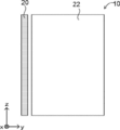
- FIG. 1 is a perspective view of the structure 10.
- FIG. 2 is a plan view of the structure 10 shown in FIG. 1 as viewed from the direction of arrow A (front direction).
- 3A to 3C are plan views of the structure 10 shown in FIG. 1 as viewed from the direction of arrow B (side direction).
- FIG. 4 shows a state in which each of the optical illusion lens 20, the side surface portion 22, and the facing surface portion 24 is separated for the purpose of explaining the configuration of the structure 10.
- the structure of the structure 10 is expressed without considering the illusion by the optical illusion lens 20.
- the structure 10 of the present embodiment intersects the side surface portion 22 and the side surface portion 22 that surrounds the visual illusion space 12 visually recognized by the observer, and is provided at one end of the side surface portion 22.
- the illusion lens 20 for illusion of the side surface portion 22 and the facing surface portion 24 facing the illusion lens 20 and provided at the other end of the side surface portion 22 are provided.
- the structure 10 of the present embodiment has a rectangular parallelepiped shape surrounding the viewing space 12 visually recognized by the observer.
- the space inside the structure 10 is the visual recognition space 12 visually recognized by the observer.
- the direction of the arrow A is the observation direction by the observer, and the observer observes the side surface portion 22 of the structure 10 and the internal viewing space 12 through the optical illusion lens 20.
- the members constituting the side surface portion 22 of the present embodiment are not particularly limited.
- it may be composed of members such as paper and wood.
- the side surface portion 22 may be configured by a display device for displaying an image on the surface 22I.
- any display device that can display an image on the surface 22I may be used, and for example, a display device that displays a still image or a digital image that is a moving image may be used. ..
- a display device such as an LCD (Liquid Crystal Display) capable of displaying a digital image
- the displayed image may be changed.
- the member on the surface 22I side that is visually recognized together with the viewing space 12 by the observer, and the member on the opposite surface 22U side.
- the member on the surface 22U side is a transparent layer such as an acrylic plate or a light transmitting layer having light transmittance such as a milky white layer
- the member on the surface 22I side is an OHP (OverHead Projector) on which an image is printed on the surface 22I side. ) It may be used as an image layer such as a sheet.
- At least one of the image and the decoration visually recognized by the observer may be formed on the side surface portion 22, more specifically, the surface portion 22I of the side surface portion 22. At least one of the image and the decoration formed on the surface 22I may be provided on the entire surface of the surface 22I or may be provided on a part of the area. Further, at least one of the image and the decoration may be provided on all of the four surfaces 22I surrounding the rectangular viewing space 12, or may be provided on a part of the surfaces.
- the "decoration" provided on the side surface portion 22 includes not only a two-dimensional object but also a three-dimensional object.
- the side surface portion 22 of the present embodiment has higher brightness than the facing surface portion 24. More specifically, the brightness of the surface 22I in contact with the viewing space 12 of the side surface portion 22 is higher than the brightness of the surface 24I in contact with the viewing space 12 of the facing surface portion 24.
- the member constituting the facing surface portion 24 of the present embodiment is not particularly limited, and may be the same as or different from the member constituting the side surface portion 22. Therefore, examples of the members constituting the facing surface portion 24 include members such as paper and wood, as well as the above-mentioned display device and the like. Further, at least one of an image and a decoration visually recognized by the observer may be formed on the facing surface portion 24, more specifically, the surface 24I of the facing surface portion 24.
- the brightness of the facing surface portion 24 of the present embodiment is lower than the brightness of the surface 22I of the side surface portion 22.
- the surface 24I of the facing surface portion 24 has lower visibility than the surface 22I of the side surface portion 22.
- the brightness of the surface 24I of the facing surface portion 24 is 1/10 or less of the brightness of the surface 22I of the side surface portion 22. It is preferably 1/100 or less, and more preferably 1/100 or less.
- the entire surface of the surface 24I of the facing surface portion 24 is black.
- the optical illusion lens 20 of the present embodiment is provided in the viewing space 12 and between the side surface portion 22 and the observer. As shown in FIG. 3A, the optical illusion lens 20 is provided so as to intersect the side surface portion 22 (more specifically, the surface 22I), and is provided at a position facing the facing surface portion 24 (see FIG. 1). ing. As an example, in the present embodiment, as shown in FIG. 3A, the optical illusion lens 20 is provided in contact with the side surface portion 22. In addition, unlike the present embodiment, as shown in FIG. 3B, the optical illusion lens 20 may be provided at a position separated from the side surface portion 22.
- the focal length of the illusion lens 20 is sufficiently longer than the length of the side surface 22 (length in the depth direction)
- the illusion lens 20 and the side surface portion 22 are moved from the focal length of the illusion lens 20 to the side surface 22. It may be separated to the length Q obtained by subtracting the length.
- the "degree” is for considering the influence of the length a of the invisible region, which will be described in detail later.
- the optical illusion lens 20 and the side surface portion 22 may be separated by Q + a.
- the optical illusion lens 20 is provided perpendicular to the side surface portion 22, more specifically, the surface 22I (see FIG. 4) (90 degrees).
- the angle formed by the optical illusion lens 20 and the surface 22I is not limited to this embodiment.
- the angle ⁇ is preferably in the range of 0 degrees or more and 90 degrees or less.
- the optical illusion lens 20 may be tilted in the range of 0 degrees or more and 90 degrees or less. This makes it possible to adjust the distance of the virtual image on each of the side surface 22 and the illusion lens 20 on the separated upper side, the side surface 22 and the illusion lens 20 on the grounded lower side, and the side surface 22 which is both of them. Is.
- the optical illusion lens 20 of the present embodiment has a function of causing the observer to illusion the side surface portion 22 so that the observer can illusion the depth of the side surface portion 22, in other words, the depth of the viewing space 12.
- a convex lens is used as the optical illusion lens 20 of the present embodiment.
- the "convex lens” include a convex lens, a convex Fresnel lens, and a convex diffractive lens.
- FIG. 5A shows a schematic view showing an example of the state of the side surface portion 22 and the facing surface portion 24 visually recognized by the observer when the optical illusion lens 20 is not provided.
- FIG. 5B shows a schematic view showing an example of the state of the side surface portion 22 and the facing surface portion 24 visually recognized by the observer when the optical illusion lens 20 is provided.
- the description of the optical illusion lens 20 is omitted.
- the observer is allowed to observe the side surface portion 22 through the illusion lens 20, so that the virtual image of the side surface portion 22 generated by the illusion lens 20 is obtained. Observed.
- FIG. 13 shows an embodiment. As shown in FIG. 13, by displaying images of the sky, trees, and the ground on the side surface by the side surface portion 22 (specifically, printing on paper and pasting on the side surface), a 3D (3 dimensions) depth is obtained. It can be shown in a certain scene.
- FIG. 13 is an example using a Fresnel type convex lens.
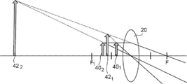
- a virtual image generated by the convex illusion lens 20 will be described with reference to FIG.
- a virtual image of the object is generated on the same side as the object with respect to the optical illusion lens 20.
- the virtual image 42 1 is formed, against the object 40 2, the virtual image 42 2 It is formed.
- it is larger in the virtual image 42 2 with respect to the object 40 2 than the virtual image 42 1 relative to the object 40 1. That is, the farther the position of the object is from the optical illusion lens 20, the larger the virtual image formed.
- a real image generated by the convex illusion lens 20 will be described with reference to FIG. 7.
- a convex lens when an object is provided at a position farther from the lens than the front focal point, a real image of the object is generated on the opposite side of the object with respect to the optical illusion lens 20.
- a real image 44 1 of the object 40 3 and opposite is formed, with respect to the object 40 4, real image 44 2 of the object 40 4 opposite direction is formed.
- the object 40 4 greater in real 44 1 relative to the object 40 3 than the real image 44 2 against. That is, the closer the position of the object is to the optical illusion lens 20, the larger the formed real image.
- the real image can be projected on the screen.
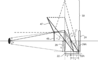
- the focal length is f
- the length of the side surface portion 22 is f + b
- the length of the invisible region is a.
- the size of the optical illusion lens 20 is S
- the visual field range of the optical illusion lens 20 is V.
- FIG. 8A shows an example in which the length b is longer than the length a of the invisible region.
- FIG. 8B shows an example in which the length b is shorter than the length a of the invisible region.
- the length b is longer than the length a of the invisible region.
- the real image of the side surface portion 22 can be seen.
- the length b is shorter than the length a of the invisible region, the real image of the side surface portion 22 cannot be seen.
- the first obstructive factor is the light beam that reaches the region that cannot be focused.
- the light rays L2 and the light rays L5 reach the region 50 where the light rays are blocked by the upper side surface portion 22 (not shown but actually existing on the paper surface) and cannot be focused.
- the region 50 that cannot be focused depends on the size S of the lens surface of the illusion lens 20, and the light rays L2 and L5 that do not pass through the illusion lens 20 cannot contribute to the image formation, which hinders the observation of the real image.
- the second obstructive factor is the light beam that does not enter the observer's eyes.
- the light passing through the optical illusion lens 20 is visually recognized when it is incident on the observer's eyes (pupil) at an angle of view or less of the optical illusion lens 20.
- the ray L3 and the ray L4 are visible to the observer, but the ray L1 is not visible to the observer.
- the real image 45 formed by the portion 22A in the side surface portion 22 that exceeds the length a of the invisible region only the tip portion is visually recognized by the observer, and the other portions are not visible, so to speak.
- the real image is 45.
- the real image 45 formed by the portion 22A exceeding the length a of the invisible region in the side surface portion 22 is an invisible real image 45 that is not visible at all.
- the length b of the facing surface portion 24 is longer than the length a of the invisible region, so that the real image is visually recognized by the observer.
- the real image 46 is visually recognized with respect to the portion 24A of the facing surface portion 24.
- the facing surface portion 24 of the present embodiment has lower brightness than the side surface portion 22, and specifically is black, the visibility is low, so that the real image 46 is suppressed from being visually recognized by the observer. be able to.
- the real image 46 with respect to the portion 24A of the facing surface portion 24 is an invisible real image that cannot be visually recognized by the observer.
- the observer can illusion the depth of the side surface portion 22.
- a lens with irregularities such as a Fresnel lens may be used to diffuse the side image by utilizing the strong scattering characteristic for light incident on the lens surface from an oblique direction to erase the real image. ..
- the distance between the facing surface of the facing surface portion 24 and the lens surface of the optical illusion lens 20 is about the focal length or less, or the real image (utilization of invisible region, utilization of scattering) is conspicuous by each measure. It can be set to a distance within a range that does not exist.
- the facing surface portion 24 may be provided with a real image portion that forms a real image by the optical illusion lens 20.
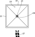
- a real image portion 25 in which an image 26 for making a real image is formed may be provided in the central portion of the surface 24I of the facing surface portion 24.
- the brightness of the real image portion 25 is preferably relatively high in consideration of visibility, and may be, for example, the same as the brightness of the side surface portion 22.
- the image 26 formed on the real image unit 25 is an image upside down from the desired real image.
- FIG. 10 shows a schematic diagram showing an example of the state of the structure 10 having the facing surface portion 24 shown in FIG. 9, which is visually recognized by the observer.
- the description of the optical illusion lens 20 is omitted.
- the real image 27 of the image 26 formed on the real image portion 25 of the facing surface portion 24 is visually recognized on the front side of the structure 10, the real image 27 seems to be floating to the observer. Looks like.
- the depth of the side surface portion 22 looks deeper than it actually is, and the real image 26 is seen on the front side of the structure 10, so that the stereoscopic effect is further emphasized.
- FIG. 14 shows an example in which the three-dimensional effect is emphasized.
- the state in which the ruler is arranged on the facing surface portion 24 is visually recognized by the observer through the optical illusion lens 20.
- the observer can visually recognize the real image of the ruler in a state of being raised toward the front side.
- the real image portion 25 of the facing surface portion 24 is large, the real image formed by the real image portion 25 and the virtual image of the side surface portion 22 may be visually recognized by the observer. Therefore, it is preferable that the size and position of the real image portion 25 are such that the real image formed by the real image portion 25 and the virtual image of the side surface portion 22 do not overlap.
- the size and position of the real image portion 25 in this case can be determined experimentally or by design of the structure 10.
- the brightness of the region 24B around the surface 24I of the facing surface portion 24 is lower than the brightness of the real image portion 25.
- the brightness of the peripheral region 24B is preferably lower than the brightness of the side surface portion 22, and is preferably black, for example.
- the optical illusion lens 20 may be a concave lens.
- the "concave lens” include a concave lens, a concave Fresnel lens, and a concave diffractive lens.
- a concave lens only a virtual image smaller than the size of the object is formed, and a real image is not formed.
- the virtual image 42 3 formed by the object 40 5 is greater than the virtual image 42 4 formed by the object 40 6. That is, the farther the position of the object is from the optical illusion lens 20, the smaller the size of the formed virtual image.
- the shape of the viewing space 12 is rectangular, but the shape of the viewing space 12, in other words, the shape of the side surface portion 22 is not limited to the present embodiment.
- the side surface portion 22 may be tubular and the viewing space 12 may be a cylindrical space.
- the embodiment in which the structure 10 is provided with the facing surface portion 24 has been described, but the facing surface portion 24 is not essential.
- the side surface portion 20 is illusioned by the observer observing through the illusion lens 20 using the structure 10 provided with the side surface portion 20 and the illusion lens 20, and the distance to the facing surface side of the illusion lens 20. That is, the depth can be illusioned.
- the side surface portion 22 and the facing surface portion 24 may be in a form that can be disassembled or a form that can be folded.
- the structure 10 of the present embodiment intersects with the side surface portion 22 surrounding the visual illusion space 12 visually recognized by the observer, and the side surface portion 22 provided at one end of the side surface portion 22.
- the optical illusion lens 20 for the optical illusion of the above is provided. The observer visually recognizes the surface 22I of the viewing space 12 and the side surface portion 22 through the optical illusion lens 20.
- the structure 10 of the present embodiment it is possible to produce a three-dimensional effect with a simple configuration. Therefore, according to the structure 10 of the present embodiment, it is possible to produce a three-dimensional effect in various scenes.
Landscapes
- Physics & Mathematics (AREA)
- General Physics & Mathematics (AREA)
- Business, Economics & Management (AREA)
- Accounting & Taxation (AREA)
- Marketing (AREA)
- Engineering & Computer Science (AREA)
- Theoretical Computer Science (AREA)
- Optics & Photonics (AREA)
- Lenses (AREA)
Priority Applications (1)
| Application Number | Priority Date | Filing Date | Title |
|---|---|---|---|
| JP2022524365A JP7413522B2 (ja) | 2020-05-22 | 2021-04-30 | 構造体及び立体感演出方法 |
Applications Claiming Priority (2)
| Application Number | Priority Date | Filing Date | Title |
|---|---|---|---|
| JP2020-090069 | 2020-05-22 | ||
| JP2020090069 | 2020-05-22 |
Publications (1)
| Publication Number | Publication Date |
|---|---|
| WO2021235218A1 true WO2021235218A1 (ja) | 2021-11-25 |
Family
ID=78708836
Family Applications (1)
| Application Number | Title | Priority Date | Filing Date |
|---|---|---|---|
| PCT/JP2021/017275 Ceased WO2021235218A1 (ja) | 2020-05-22 | 2021-04-30 | 構造体及び立体感演出方法 |
Country Status (2)
| Country | Link |
|---|---|
| JP (1) | JP7413522B2 (https=) |
| WO (1) | WO2021235218A1 (https=) |
Citations (2)
| Publication number | Priority date | Publication date | Assignee | Title |
|---|---|---|---|---|
| JPH01177729U (https=) * | 1988-06-03 | 1989-12-19 | ||
| JP2005338346A (ja) * | 2004-05-26 | 2005-12-08 | Casio Comput Co Ltd | 液晶表示装置 |
-
2021
- 2021-04-30 JP JP2022524365A patent/JP7413522B2/ja active Active
- 2021-04-30 WO PCT/JP2021/017275 patent/WO2021235218A1/ja not_active Ceased
Patent Citations (2)
| Publication number | Priority date | Publication date | Assignee | Title |
|---|---|---|---|---|
| JPH01177729U (https=) * | 1988-06-03 | 1989-12-19 | ||
| JP2005338346A (ja) * | 2004-05-26 | 2005-12-08 | Casio Comput Co Ltd | 液晶表示装置 |
Also Published As
| Publication number | Publication date |
|---|---|
| JP7413522B2 (ja) | 2024-01-15 |
| JPWO2021235218A1 (https=) | 2021-11-25 |
Similar Documents
| Publication | Publication Date | Title |
|---|---|---|
| US9857604B2 (en) | Stereoscopic display | |
| KR100910393B1 (ko) | 넓은 시야각을 갖는 실감 영상 디스플레이 장치 | |
| JP5454661B2 (ja) | 画像表示装置 | |
| KR100656575B1 (ko) | 3차원 입체 동영상 디스플레이 장치 | |
| JP5649936B2 (ja) | 画像表示装置 | |
| US20100097447A1 (en) | Image Display Device | |
| CN114766013A (zh) | 中继系统 | |
| CN103091850A (zh) | 裸视多维显示组件及其显示器 | |
| JP4546505B2 (ja) | 空間映像投映装置及びその方法 | |
| JP2016500829A (ja) | 収束角度スライス型の真の3dディスプレイ | |
| KR102447047B1 (ko) | 공간 영상 투영 장치 | |
| WO2021085287A1 (ja) | 画像表示装置 | |
| JP4341308B2 (ja) | 空中像表示装置 | |
| CN113589540B (zh) | 扩束光学膜、显示装置和多方向扩束光学膜 | |
| US20120105805A1 (en) | Image viewing systems with curved screens | |
| JP7413522B2 (ja) | 構造体及び立体感演出方法 | |
| CN104267573A (zh) | 基于视差的新型裸眼悬浮立体显示方法 | |
| TWI707160B (zh) | 影像顯示裝置 | |
| WO2009091365A1 (en) | Display system | |
| JPWO2009136582A1 (ja) | 画像表示物 | |
| US11899215B1 (en) | Head mounted display, display device and image display method thereof | |
| JP4893821B2 (ja) | 画像表示装置 | |
| CN104270628A (zh) | 基于菲涅尔透镜的裸眼悬浮立体显示系统及使用方法 | |
| Momonoi et al. | 48‐2: Flipping‐free Light Field Mirage Using Multiple Light Field Displays | |
| JP6554044B2 (ja) | 映像表示装置及び映像表示方法 |
Legal Events
| Date | Code | Title | Description |
|---|---|---|---|
| 121 | Ep: the epo has been informed by wipo that ep was designated in this application |
Ref document number: 21807830 Country of ref document: EP Kind code of ref document: A1 |
|
| ENP | Entry into the national phase |
Ref document number: 2022524365 Country of ref document: JP Kind code of ref document: A |
|
| NENP | Non-entry into the national phase |
Ref country code: DE |
|
| 122 | Ep: pct application non-entry in european phase |
Ref document number: 21807830 Country of ref document: EP Kind code of ref document: A1 |