WO2021235166A1 - 電池及びその製造方法 - Google Patents
電池及びその製造方法 Download PDFInfo
- Publication number
- WO2021235166A1 WO2021235166A1 PCT/JP2021/016255 JP2021016255W WO2021235166A1 WO 2021235166 A1 WO2021235166 A1 WO 2021235166A1 JP 2021016255 W JP2021016255 W JP 2021016255W WO 2021235166 A1 WO2021235166 A1 WO 2021235166A1
- Authority
- WO
- WIPO (PCT)
- Prior art keywords
- metal layer
- power generation
- layer
- generation element
- inner terminal
- Prior art date
- Legal status (The legal status is an assumption and is not a legal conclusion. Google has not performed a legal analysis and makes no representation as to the accuracy of the status listed.)
- Ceased
Links
Images




Classifications
-
- H—ELECTRICITY
- H01—ELECTRIC ELEMENTS
- H01M—PROCESSES OR MEANS, e.g. BATTERIES, FOR THE DIRECT CONVERSION OF CHEMICAL ENERGY INTO ELECTRICAL ENERGY
- H01M50/00—Constructional details or processes of manufacture of the non-active parts of electrochemical cells other than fuel cells, e.g. hybrid cells
- H01M50/50—Current conducting connections for cells or batteries
- H01M50/543—Terminals
- H01M50/564—Terminals characterised by their manufacturing process
-
- H—ELECTRICITY
- H01—ELECTRIC ELEMENTS
- H01M—PROCESSES OR MEANS, e.g. BATTERIES, FOR THE DIRECT CONVERSION OF CHEMICAL ENERGY INTO ELECTRICAL ENERGY
- H01M10/00—Secondary cells; Manufacture thereof
- H01M10/05—Accumulators with non-aqueous electrolyte
- H01M10/052—Li-accumulators
-
- H—ELECTRICITY
- H01—ELECTRIC ELEMENTS
- H01M—PROCESSES OR MEANS, e.g. BATTERIES, FOR THE DIRECT CONVERSION OF CHEMICAL ENERGY INTO ELECTRICAL ENERGY
- H01M50/00—Constructional details or processes of manufacture of the non-active parts of electrochemical cells other than fuel cells, e.g. hybrid cells
- H01M50/10—Primary casings; Jackets or wrappings
- H01M50/102—Primary casings; Jackets or wrappings characterised by their shape or physical structure
- H01M50/105—Pouches or flexible bags
-
- H—ELECTRICITY
- H01—ELECTRIC ELEMENTS
- H01M—PROCESSES OR MEANS, e.g. BATTERIES, FOR THE DIRECT CONVERSION OF CHEMICAL ENERGY INTO ELECTRICAL ENERGY
- H01M50/00—Constructional details or processes of manufacture of the non-active parts of electrochemical cells other than fuel cells, e.g. hybrid cells
- H01M50/10—Primary casings; Jackets or wrappings
- H01M50/116—Primary casings; Jackets or wrappings characterised by the material
- H01M50/117—Inorganic material
- H01M50/119—Metals
-
- H—ELECTRICITY
- H01—ELECTRIC ELEMENTS
- H01M—PROCESSES OR MEANS, e.g. BATTERIES, FOR THE DIRECT CONVERSION OF CHEMICAL ENERGY INTO ELECTRICAL ENERGY
- H01M50/00—Constructional details or processes of manufacture of the non-active parts of electrochemical cells other than fuel cells, e.g. hybrid cells
- H01M50/10—Primary casings; Jackets or wrappings
- H01M50/116—Primary casings; Jackets or wrappings characterised by the material
- H01M50/121—Organic material
-
- H—ELECTRICITY
- H01—ELECTRIC ELEMENTS
- H01M—PROCESSES OR MEANS, e.g. BATTERIES, FOR THE DIRECT CONVERSION OF CHEMICAL ENERGY INTO ELECTRICAL ENERGY
- H01M50/00—Constructional details or processes of manufacture of the non-active parts of electrochemical cells other than fuel cells, e.g. hybrid cells
- H01M50/10—Primary casings; Jackets or wrappings
- H01M50/116—Primary casings; Jackets or wrappings characterised by the material
- H01M50/124—Primary casings; Jackets or wrappings characterised by the material having a layered structure
- H01M50/126—Primary casings; Jackets or wrappings characterised by the material having a layered structure comprising three or more layers
-
- H—ELECTRICITY
- H01—ELECTRIC ELEMENTS
- H01M—PROCESSES OR MEANS, e.g. BATTERIES, FOR THE DIRECT CONVERSION OF CHEMICAL ENERGY INTO ELECTRICAL ENERGY
- H01M50/00—Constructional details or processes of manufacture of the non-active parts of electrochemical cells other than fuel cells, e.g. hybrid cells
- H01M50/10—Primary casings; Jackets or wrappings
- H01M50/116—Primary casings; Jackets or wrappings characterised by the material
- H01M50/124—Primary casings; Jackets or wrappings characterised by the material having a layered structure
- H01M50/126—Primary casings; Jackets or wrappings characterised by the material having a layered structure comprising three or more layers
- H01M50/129—Primary casings; Jackets or wrappings characterised by the material having a layered structure comprising three or more layers with two or more layers of only organic material
-
- H—ELECTRICITY
- H01—ELECTRIC ELEMENTS
- H01M—PROCESSES OR MEANS, e.g. BATTERIES, FOR THE DIRECT CONVERSION OF CHEMICAL ENERGY INTO ELECTRICAL ENERGY
- H01M50/00—Constructional details or processes of manufacture of the non-active parts of electrochemical cells other than fuel cells, e.g. hybrid cells
- H01M50/50—Current conducting connections for cells or batteries
- H01M50/528—Fixed electrical connections, i.e. not intended for disconnection
-
- H—ELECTRICITY
- H01—ELECTRIC ELEMENTS
- H01M—PROCESSES OR MEANS, e.g. BATTERIES, FOR THE DIRECT CONVERSION OF CHEMICAL ENERGY INTO ELECTRICAL ENERGY
- H01M50/00—Constructional details or processes of manufacture of the non-active parts of electrochemical cells other than fuel cells, e.g. hybrid cells
- H01M50/50—Current conducting connections for cells or batteries
- H01M50/531—Electrode connections inside a battery casing
-
- H—ELECTRICITY
- H01—ELECTRIC ELEMENTS
- H01M—PROCESSES OR MEANS, e.g. BATTERIES, FOR THE DIRECT CONVERSION OF CHEMICAL ENERGY INTO ELECTRICAL ENERGY
- H01M50/00—Constructional details or processes of manufacture of the non-active parts of electrochemical cells other than fuel cells, e.g. hybrid cells
- H01M50/50—Current conducting connections for cells or batteries
- H01M50/531—Electrode connections inside a battery casing
- H01M50/533—Electrode connections inside a battery casing characterised by the shape of the leads or tabs
-
- H—ELECTRICITY
- H01—ELECTRIC ELEMENTS
- H01M—PROCESSES OR MEANS, e.g. BATTERIES, FOR THE DIRECT CONVERSION OF CHEMICAL ENERGY INTO ELECTRICAL ENERGY
- H01M50/00—Constructional details or processes of manufacture of the non-active parts of electrochemical cells other than fuel cells, e.g. hybrid cells
- H01M50/50—Current conducting connections for cells or batteries
- H01M50/531—Electrode connections inside a battery casing
- H01M50/534—Electrode connections inside a battery casing characterised by the material of the leads or tabs
-
- H—ELECTRICITY
- H01—ELECTRIC ELEMENTS
- H01M—PROCESSES OR MEANS, e.g. BATTERIES, FOR THE DIRECT CONVERSION OF CHEMICAL ENERGY INTO ELECTRICAL ENERGY
- H01M50/00—Constructional details or processes of manufacture of the non-active parts of electrochemical cells other than fuel cells, e.g. hybrid cells
- H01M50/50—Current conducting connections for cells or batteries
- H01M50/543—Terminals
- H01M50/552—Terminals characterised by their shape
- H01M50/553—Terminals adapted for prismatic, pouch or rectangular cells
-
- H—ELECTRICITY
- H01—ELECTRIC ELEMENTS
- H01M—PROCESSES OR MEANS, e.g. BATTERIES, FOR THE DIRECT CONVERSION OF CHEMICAL ENERGY INTO ELECTRICAL ENERGY
- H01M2220/00—Batteries for particular applications
- H01M2220/20—Batteries in motive systems, e.g. vehicle, ship, plane
-
- Y—GENERAL TAGGING OF NEW TECHNOLOGICAL DEVELOPMENTS; GENERAL TAGGING OF CROSS-SECTIONAL TECHNOLOGIES SPANNING OVER SEVERAL SECTIONS OF THE IPC; TECHNICAL SUBJECTS COVERED BY FORMER USPC CROSS-REFERENCE ART COLLECTIONS [XRACs] AND DIGESTS
- Y02—TECHNOLOGIES OR APPLICATIONS FOR MITIGATION OR ADAPTATION AGAINST CLIMATE CHANGE
- Y02E—REDUCTION OF GREENHOUSE GAS [GHG] EMISSIONS, RELATED TO ENERGY GENERATION, TRANSMISSION OR DISTRIBUTION
- Y02E60/00—Enabling technologies; Technologies with a potential or indirect contribution to GHG emissions mitigation
- Y02E60/10—Energy storage using batteries
-
- Y—GENERAL TAGGING OF NEW TECHNOLOGICAL DEVELOPMENTS; GENERAL TAGGING OF CROSS-SECTIONAL TECHNOLOGIES SPANNING OVER SEVERAL SECTIONS OF THE IPC; TECHNICAL SUBJECTS COVERED BY FORMER USPC CROSS-REFERENCE ART COLLECTIONS [XRACs] AND DIGESTS
- Y02—TECHNOLOGIES OR APPLICATIONS FOR MITIGATION OR ADAPTATION AGAINST CLIMATE CHANGE
- Y02P—CLIMATE CHANGE MITIGATION TECHNOLOGIES IN THE PRODUCTION OR PROCESSING OF GOODS
- Y02P70/00—Climate change mitigation technologies in the production process for final industrial or consumer products
- Y02P70/50—Manufacturing or production processes characterised by the final manufactured product
Definitions
- This disclosure relates to batteries and their manufacturing methods.
- the conventional battery has a problem that when the power generation element is enclosed in an exterior body such as a laminated film, the position of the power generation element is displaced with respect to the exterior body.
- a battery using an adhesive layer to suppress this misalignment is known (see, for example, Patent Document 1).
- Patent Document 1 describes an all-solid-state battery laminate having at least one unit all-solid-state battery, a positive electrode terminal and a negative electrode terminal connected to a positive electrode current collector layer and a negative electrode current collector layer, respectively, and an all-solid-state battery laminate.
- a battery comprising an exterior body bottom member constituting an exterior body that encloses the body. Further, in this battery, at least between the positive electrode collector layer or the negative electrode current collector layer of the all-solid-state battery laminate and the exterior body bottom member, and between the positive electrode terminal and the negative electrode terminal and the exterior body bottom member. There is an adhesive layer in one place.
- the battery according to one aspect of the present disclosure includes a power generation element including a positive electrode layer, a negative electrode layer, and an electrolyte layer located between the positive electrode layer and the negative electrode layer, and an inner side electrically connected to the power generation element.
- a terminal electrode, a power generation element, and a laminated film accommodating the inner terminal electrode are provided, and the laminated film includes a metal layer and an inner resin layer located closer to the power generation element than the metal layer. It has an outer resin layer located on the opposite side of the inner resin layer with respect to the metal layer, and the inner resin layer is provided with an inner opening in which the metal layer is exposed, and the inner terminal electrode is provided.
- the inner terminal electrode and the metal layer each have an uneven surface, and the inner terminal has an uneven surface.
- the uneven surface of the electrode and the uneven surface of the metal layer are in mesh with each other.
- a method for manufacturing a battery according to one aspect of the present disclosure includes a power generation element including a positive electrode layer, a negative electrode layer, and an electrolyte layer located between the positive electrode layer and the negative electrode layer, an inner terminal electrode, and the power generation element.
- a method for manufacturing a battery including a laminated film accommodating the inner terminal electrode, the metal layer and an inner resin layer located closer to the power generation element than the metal layer.
- a preparatory step for preparing the laminated film having an inner opening in which the metal layer is exposed in the inner resin layer, an arrangement step for arranging a structure in the inner opening, and the power generation element.
- the inner terminal electrode electrically connected to the metal layer is pressed so as to be electrically connected to the metal layer at the inner opening where the structure is arranged in the process of arranging the structure.
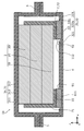
- FIG. 1 is a cross-sectional view showing a schematic configuration of the battery according to the first embodiment.
- FIG. 2A is an enlarged cross-sectional view of the perimeter of the structure in region II of FIG.
- FIG. 2B is an enlarged exploded cross-sectional view of the structure in region II of FIG.
- FIG. 3 is a plan view clearly showing the positional relationship between the inner terminal electrode, the inner opening, and the structure according to the first embodiment.
- FIG. 4A is a cross-sectional view showing one step of the battery manufacturing method according to the first embodiment.
- FIG. 4B is a cross-sectional view showing one step of the battery manufacturing method according to the first embodiment.
- FIG. 4C is a cross-sectional view showing one step of the battery manufacturing method according to the first embodiment.
- FIG. 4A is a cross-sectional view showing one step of the battery manufacturing method according to the first embodiment.
- FIG. 4B is a cross-sectional view showing one step of the battery manufacturing method according to the first embodiment.
- FIG. 5 is a plan view clearly showing the positional relationship between the inner terminal electrode, the inner opening, and the structure according to the modified example of the first embodiment.
- FIG. 6 is an enlarged cross-sectional view of the periphery of the structure of the battery according to the modified example of the first embodiment.
- FIG. 7 is a cross-sectional view showing a schematic configuration of the battery according to the second embodiment.
- FIG. 8 is a cross-sectional view showing a schematic configuration of the battery according to the third embodiment.
- FIG. 9 is a cross-sectional view showing a schematic configuration of the battery according to the fourth embodiment.
- the present inventors have found that in a battery, particularly an all-solid-state battery, the following problems occur when the power generation element is enclosed in a laminated film.
- the volatile substances of the adhesive in the adhesive layer volatilize in the sealing process, which may cause a deterioration in the performance of the power generation element. Further, there is a problem that the adhesive shrinks due to curing, and the stress generated at that time causes distortion in the power generation element. Distortion can reduce the reliability of the battery, such as performance degradation of the power generation element, damage to the power generation element, or misalignment due to peeling of the power generation element from the adhesive portion. Further, it is necessary to accurately position the power generation element at the place where the adhesive layer is formed, which causes a problem that the process becomes unnecessarily complicated.
- the battery according to one aspect of the present disclosure includes a power generation element including a positive electrode layer, a negative electrode layer, and an electrolyte layer located between the positive electrode layer and the negative electrode layer, and an inner side electrically connected to the power generation element.
- a terminal electrode, a power generation element, and a laminated film accommodating the inner terminal electrode are provided, and the laminated film includes a metal layer and an inner resin layer located closer to the power generation element than the metal layer. It has an outer resin layer located on the opposite side of the inner resin layer with respect to the metal layer, and the inner resin layer is provided with an inner opening in which the metal layer is exposed, and the inner terminal electrode is provided.
- the inner terminal electrode and the metal layer each have an uneven surface, and the inner terminal has an uneven surface.
- the uneven surface of the electrode and the uneven surface of the metal layer are in mesh with each other.
- the power generation element can be positioned by engaging the uneven surface of the inner terminal electrode with the uneven surface of the metal layer. Further, when the power generation element is housed in the laminated film in the battery manufacturing process, the positional deviation of the power generation element can be suppressed by engaging the uneven surface of the inner terminal electrode with the uneven surface of the metal layer.
- the relative positioning between the power generation element and the laminated film can be easily performed, and a highly reliable battery can be realized.
- the metal layer may have a metal layer main body and a structure, and the convex portion of the uneven surface of the metal layer may be a part of the structure.
- the power generation element can be positioned. Further, when the power generation element is housed in the laminated film in the battery manufacturing process, the positional deviation of the power generation element can be suppressed by embedding the structure in the metal layer main body and the inner terminal electrode.
- the relative positioning between the power generation element and the laminated film can be easily performed, and a highly reliable battery can be realized.
- the structure may have conductivity.
- the electrical conductivity from the power generation element to the metal layer via the inner terminal electrode can be enhanced, so that the reliability of the battery can be further enhanced.
- the structure may be made of metal.
- the structure may be spherical particles.
- the area in contact between the inner terminal electrode and the metal layer body and the structure can be reduced, so that a strong pressure is applied to the place where the inner terminal electrode and the metal layer body and the structure are in contact with each other. It takes. Therefore, the structure is easily embedded in the metal layer main body and the inner terminal electrode, and the misalignment of the power generation element can be suppressed. Therefore, the reliability of the battery can be further improved.
- the inner terminal electrode may be in contact with the side surface and the main surface of the power generation element.
- the outer resin layer may be provided with an outer opening in which the metal layer is exposed.
- the battery according to one aspect of the present disclosure may further include an outer terminal electrode that is electrically connected to the metal layer at the outer opening.
- the thickness of the metal layer in the inner opening may be thicker than the thickness of the metal layer in the region where the metal layer is not exposed.
- the size of the convex portion of the uneven surface can be increased, and the misalignment of the power generation element can be further suppressed in the battery manufacturing process.
- the damage of the metal layer can be suppressed at the place where the convex portion of the uneven surface and the metal layer come into contact with each other. Therefore, the reliability of the battery can be further improved.
- the thickness of all the metal layers in the laminated film is not increased, the weight of the laminated film is unlikely to increase. Therefore, the weight energy density of the battery is improved. Further, since the laminated film can maintain the flexibility, the productivity of the battery is improved and the cost can be reduced.
- the electrolyte layer may be a solid electrolyte layer containing a solid electrolyte having lithium ion conductivity.
- the relative positioning between the power generation element and the laminated film can be easily performed, and the reliability can be improved.
- the method for manufacturing a battery includes a power generation element including a positive electrode layer, a negative electrode layer, and an electrolyte layer located between the positive electrode layer and the negative electrode layer, an inner terminal electrode, and the above.
- a method for manufacturing a battery comprising a power generation element and a laminated film accommodating the inner terminal electrode, wherein the metal layer and the inner resin layer located closer to the power generation element than the metal layer.
- the inner resin layer is provided with an inner opening in which the metal layer is exposed, a preparatory step for preparing the laminated film, an arrangement step for arranging the structure in the inner opening, and the above.
- a pressing step of pressing the inner terminal electrode electrically connected to the power generation element so as to be electrically connected to the metal layer at the inner opening in which the structure is arranged in the process of arranging the structure. include.
- the structure can be embedded in the metal layer body and the inner terminal electrode, so that the power generation element can be positioned. Further, when the power generation element is housed in the laminated film in the battery manufacturing process, the positional deviation of the power generation element can be suppressed by embedding the structure in the metal layer main body and the inner terminal electrode.
- the relative positioning between the power generation element and the laminated film can be easily performed, and a highly reliable battery can be manufactured.
- each figure is a schematic diagram and is not necessarily exactly illustrated. Therefore, for example, the scales and the like do not always match in each figure. Further, in each figure, substantially the same configuration is designated by the same reference numeral, and duplicate description will be omitted or simplified.
- plan view means a case where the battery is viewed along the stacking direction of the battery, and the figure at that time is taken as a plan view.
- thickness is the length of the battery and each layer in the stacking direction.
- inside and outside in “inside” and “outside” mean “inside” in the direction approaching the center of the battery and away from the center of the battery unless otherwise specified. Is “outside”.
- the terms “upper” and “lower” in the battery configuration do not refer to the upward direction (vertically upward) and the downward direction (vertically downward) in absolute spatial recognition, but in the laminated configuration. It is used as a term defined by the relative positional relationship based on the stacking order. Also, the terms “upper” and “lower” are used not only when the two components are spaced apart from each other and another component exists between the two components, but also when the two components are present. It also applies when the two components are placed in close contact with each other and touch each other.
- the x-axis, y-axis, and z-axis indicate the three axes of the three-dimensional Cartesian coordinate system.
- the upper surface of the power generation element and the xy plane are parallel, and the direction perpendicular to the xy plane is the z-axis direction.
- the z-axis positive direction may be described as upward and the z-axis negative direction may be described as downward.
- FIG. 1 is a cross-sectional view showing a schematic configuration of the battery 1 according to the present embodiment.
- FIG. 2A is an enlarged cross-sectional view of the periphery of the structure 10 in region II of FIG.
- the battery 1 includes a power generation element 2, inner terminal electrodes 71 and 72, and a laminated film 3.
- the laminated film 3 has a first laminated film 31, a second laminated film 32, and a sealing portion 5.
- the first laminated film 31 has an inner resin layer 311, a metal layer 312, and an outer resin layer 313.
- the second laminated film 32 has an inner resin layer 321, a metal layer 322, and an outer resin layer 323.
- the inner resin layer 321 of the second laminated film 32 is provided with inner openings 91 and 92 from which the metal layer 322 is exposed.
- the metal layer 322 of the second laminated film 32 has a metal layer main body 11 and a structure 10.
- Each of the inner terminal electrodes 71 and 72 is in contact with each of the side surfaces 22 and 23 of the power generation element 2 and the main surface (here, the bottom surface 21), and draws current from the power generation element 2.
- Each of the inner terminal electrodes 71 and 72 is configured to be electrically connected to the metal layer 322 at each of the inner openings 91 and 92.
- the inner terminal electrode 71 and the metal layer 322 have an uneven surface 61 and an uneven surface 81, respectively. ing.
- the uneven surface 61 of the inner terminal electrode 71 and the uneven surface 81 of the metal layer 322 are in mesh with each other.
- the convex portion of the uneven surface 81 of the metal layer 322 is a part of the structure 10.
- the structure 10 is embedded in both the inner terminal electrode 71 and the metal layer main body 11.
- the inner terminal electrode 72 and the metal layer 322 in the inner opening 92 have the same configuration.
- the structure 10 mainly exerts its function in the step of sealing the power generation element 2 to the laminated film 3.
- the sealing step is performed in a decompression space using a decompression chamber. Details will be described later with reference to FIGS. 4A to 4C, but the sealing process will be briefly described below.
- the second laminated film 32 provided with the inner openings 91 and 92 is arranged in the decompression chamber.
- the inner openings 91 and 92 are provided so as to extend along the y-axis direction in FIG.
- the power generation element 2 provided with the inner terminal electrodes 71 and 72 is arranged above the second laminated film 32.
- the structure 10 is arranged above the metal layer main body 11 in each of the inner openings 91 and 92, and the inner terminal electrodes 71 and 72 of the power generation element 2 are inside via the structure 10, respectively. Arranged so as to be located above the openings 91 and 92.
- the structure 10 is embedded in each of the inner terminal electrodes 71 and 72 and the metal layer main body 11.
- the structure 10 makes it difficult for the power generation element 2 to move with respect to the second laminated film 32, that is, the arrangement position of the power generation element 2 is determined. In other words, the power generation element 2 is positioned.
- the first laminated film 31 is arranged so as to cover the power generation element 2.
- the pressure in the pressure reducing chamber is reduced, and the end portion of the first laminated film 31 and the end portion of the second laminated film 32 are bonded together.
- the sealing portion 5 is formed so as to surround the first laminated film 31 and the second laminated film 32.
- the power generation element 2 When the pressure is returned to normal pressure after bonding, the first laminated film 31 and the second laminated film 32 are covered along the power generation element 2 due to the atmospheric pressure of the atmosphere.
- the power generation element 2 receives an external force due to the air flow in the atmosphere when the pressure rises to normal pressure and the deformation or movement of the laminated film 3 due to this air flow.
- the power generation element 2 may move due to these external forces, causing a misalignment.
- the structure 10 is embedded in each of the inner terminal electrodes 71 and 72 and the metal layer main body 11. Therefore, even if these external forces are applied to the power generation element 2, the movement of the power generation element 2 is restricted, and the misalignment of the power generation element 2 is suppressed.
- the adhesive does not have an adhesive portion, the performance of the power generation element 2 is deteriorated due to the volatile substance in the adhesive, the power generation element 2 is damaged due to deformation, and the adhesive portion is formed due to the deformation of the power generation element 2. No peeling occurs.
- the battery 1 according to the present embodiment includes a power generation element 2 composed of a laminated body including a positive electrode layer, a negative electrode layer, and a solid electrolyte layer, inner terminal electrodes 71 and 72, and a laminated film 3.
- the battery 1 is, for example, an all-solid-state battery.
- the power generation element 2 includes at least one battery cell 20.
- the power generation element 2 includes three battery cells 20.
- the three battery cells 20 are stacked so as to be electrically connected in series.
- Each of the battery cells 20 has a structure in which a positive electrode layer, an electrolyte layer, and a negative electrode layer are laminated in this order.
- Each of the battery cells 20 includes a first electrode layer, a second electrode layer, and a solid electrolyte layer.
- the first electrode layer includes a first current collector and a first active material layer.
- the first active material layer is located between the first current collector and the solid electrolyte layer.
- the second electrode layer includes a second current collector and a second active material layer.
- the second active material layer is located between the second current collector and the solid electrolyte layer.
- the first current collector is a positive electrode current collector
- the first active material layer is a positive electrode active material layer
- the second current collector is a negative electrode current collector
- the second active material layer is a negative electrode active material layer.
- each of the battery cells 20 has a structure in which the positive electrode current collector, the positive electrode active material layer, the solid electrolyte layer, the negative electrode active material layer, and the negative electrode current collector are laminated in this order. doing.
- the first electrode layer may be a negative electrode layer, and the second electrode layer may be a positive electrode layer. That is, the first current collector is a negative electrode current collector, and the first active material layer may contain a negative electrode active material.
- the second current collector is a positive electrode current collector, and the second active material layer may contain a positive electrode active material.
- the first current collector, the first active material layer, the solid electrolyte layer, the second active material layer, and the second current collector each have a rectangular shape in a plan view.
- the plan-view shape of the first current collector, the first active material layer, the solid electrolyte layer, the second active material layer, and the second current collector is not particularly limited and may be square, round, elliptical, or It may be a shape other than a rectangle such as a polygon. That is, the battery cell 20 in which the first current collector, the first active material layer, the solid electrolyte layer, the second active material layer, and the second current collector are laminated has the same shape as described above.
- the first current collector, the first active material layer, the solid electrolyte layer, the second active material layer and the second current collector have the same size as each other, and the contours of the first current collector, the first active material layer, the solid electrolyte layer and the second current collector are the same in plan view.
- the first active material layer may be smaller than the second active material layer.
- the first active material layer and the second active material layer may be smaller than the solid electrolyte layer.
- the first and second current collectors include, for example, copper, aluminum, nickel, iron, stainless steel, platinum or gold, or a foil-like body, a plate-like body, or an alloy of two or more of these. A mesh-like body or the like is used.
- the first active material layer which is the positive electrode active material layer, contains at least the positive electrode active material.
- the first active material layer may contain at least one of a solid electrolyte, a conductive auxiliary agent and a binder (that is, a binder), if necessary.
- the positive electrode active material a known material capable of occluding and releasing (inserting and desorbing, or dissolving and precipitating) lithium ions, sodium ions or magnesium ions can be used.
- a material capable of releasing and inserting lithium ions for example, lithium cobalt oxide composite oxide (LCO), lithium nickel oxide composite oxide (LNO), lithium manganate composite oxide (LMO). ), Lithium-manganese-nickel composite oxide (LMNO), lithium-manganese-cobalt composite oxide (LMCO), lithium-nickel-cobalt composite oxide (LNCO) or lithium-nickel-manganese-cobalt composite oxide (LNMCO). ) Etc. are used.
- the solid electrolyte a known material such as a lithium ion conductor, a sodium ion conductor, or a magnesium ion conductor can be used.
- a known material such as a lithium ion conductor, a sodium ion conductor, or a magnesium ion conductor can be used.
- an inorganic solid electrolyte or a polymer solid electrolyte (including a gel-like solid electrolyte) can be used.
- the inorganic solid electrolyte for example, a sulfide solid electrolyte or an oxide solid electrolyte is used.
- the sulfide solid electrolyte in the case of a material capable of conducting lithium ions, for example, a composite composed of lithium sulfide (Li 2 S) and 2 phosphorus pentasulfide (P 2 S 5) is used.
- a composite composed of lithium sulfide (Li 2 S) and 2 phosphorus pentasulfide (P 2 S 5) is used.
- Li 2 S-SiS 2 2 Li 2 S-SiS 2
- sulfides such as Li 2 S-B 2 S 3 or Li 2 S-GeS 2
- the sulfide solid electrolyte the Li 3 N as an additive to the sulfide, LiCl, LiBr, Li 3 PO 4 and Li 4 sulphides at least one is added of SiO 4 may be used ..
- the oxide solid electrolyte in the case of a material capable of conducting lithium ions, for example, Li 7 La 3 Zr 2 O 12 (LLZ), Li 1.3 Al 0.3 Ti 1.7 (PO 4 ) 3 (LATP). Alternatively, (La, Li) TiO 3 (LLTO) or the like is used.
- LLZ Li 7 La 3 Zr 2 O 12
- LATP Li 1.3 Al 0.3 Ti 1.7 (PO 4 ) 3
- (La, Li) TiO 3 (LLTO) or the like is used.
- a conductive material such as acetylene black, carbon black, graphite or carbon fiber is used.
- a binder for example, a binder for binding such as polyvinylidene fluoride is used.
- the second active material layer which is the negative electrode active material layer, contains at least the negative electrode active material. If necessary, the second active material layer may contain at least one of a solid electrolyte, a conductive auxiliary agent, and a binder, similarly to the positive electrode active material layer.
- the negative electrode active material a known material capable of occluding and releasing (inserting and desorbing, or dissolving and precipitating) lithium ions, sodium ions or magnesium ions can be used.
- the negative electrode active material in the case of a material capable of releasing and inserting lithium ions, for example, carbon materials such as natural graphite, artificial graphite, graphite carbon fiber or resin calcined carbon, metallic lithium, lithium alloy or lithium and transition metal. Oxides with elements are used.
- the solid electrolyte layer contains at least a solid electrolyte.
- the solid electrolyte layer may contain a binder, if necessary.
- the solid electrolyte layer may contain a solid electrolyte having lithium ion conductivity.
- the above-mentioned solid electrolyte and the binder can be used as the solid electrolyte and the binder contained in the solid electrolyte layer.
- the power generation element 2 may include one or more battery cells 20.
- the power generation element 2 includes a plurality of battery cells 20 as in the present embodiment, it is preferable that the plurality of battery cells 20 are stacked.
- the plurality of battery cells 20 may be stacked in any way as long as they function as batteries.
- the plurality of battery cells 20 are stacked so as to be electrically connected in series.
- the plurality of battery cells 20 may be stacked so as to be connected in parallel.
- the number of the battery cells 20 included in the power generation element 2 may be two or three or more, and is not particularly limited.
- the plurality of battery cells 20 may have a structure in which adjacent battery cells 20 share a positive electrode current collector or a negative electrode current collector. That is, the positive electrode layer or the negative electrode layer contained in one battery cell 20 does not have to include a current collector, and the positive electrode active material layer or the negative electrode active material layer provided on the current collector of the adjacent battery cell 20. May include.
- the side surfaces 22 and 23 may be covered with a sealing member made of a sealing resin or the like.
- the laminated film 3 composed of the first and second laminated films 31 and 32 will be described.
- the laminated film 3 is a flexible film-shaped exterior body that houses the power generation element 2 and the inner terminal electrodes 71 and 72.
- the laminated film 3 covers the surface of the power generation element 2 and is provided to protect the power generation element 2 from moisture, air, and the like.
- the laminated film 3 has a first laminated film 31, a second laminated film 32, and a sealing portion 5 which is a portion to which the first laminated film 31 and the second laminated film 32 are bonded.
- the first laminated film 31 is a film that covers the upper surface 24 side of the power generation element 2
- the second laminated film 32 is a film that covers the bottom surface 21 side of the power generation element 2.
- the first laminated film 31 has a metal layer 312, an inner resin layer 311 and an outer resin layer 313.
- the second laminated film 32 has a metal layer 322, an inner resin layer 321 and an outer resin layer 323.
- the inner resin layers 311 and 321 are located closer to the power generation element 2 than the metal layers 312 and 322, respectively, and the outer resin layers 313 and 323 are on the opposite sides of the inner resin layers 311 and 321 with respect to the metal layers 312 and 322, respectively. Located in. That is, in each of the first and second laminated films 31 and 32, the outer resin layers 313 and 323, the metal layers 312 and 322, and the inner resin layers 311 and 321 are laminated in this order toward the center of the battery. ing.
- the inner resin layer 321 of the second laminated film 32 is provided with inner openings 91 and 92, which are spaces where the metal layer 322 is exposed. That is, in the inner openings 91 and 92, the metal layer 322 is not covered by the inner resin layer 321.
- the inner terminal electrodes 71 and 72 included in the battery 1 are electrically connected to the metal layer 322 at the inner openings 91 and 92, respectively. Therefore, the inner openings 91 and 92 have a structure in which the inner resin layer 321 is removed according to the shapes of the inner terminal electrodes 71 and 72.
- the metal layer 322 has an uneven surface 81. That is, the uneven surface 81 is the upper surface of the metal layer 322 in the inner openings 91 and 92.
- FIG. 2B is an enlarged exploded cross-sectional view of the periphery of the structure 10 in the region II of FIG.
- the metal layer 322 has a metal layer main body 11 and a structure 10.
- the structure 10 is a particle located between the metal layer main body 11 and the inner terminal electrodes 71 and 72.
- the structure 10 is a spherical particle.
- the structure 10 may be a rectangular parallelepiped or a cube.
- the size of the structure 10 is defined as the length of the maximum side of the smallest rectangular parallelepiped that can completely accommodate one structure 10.
- the size of the structure 10 is preferably several ⁇ m or more and several tens of ⁇ m or less.
- the structure 10 has conductivity and is particularly made of a low resistance metal.
- the structure 10 is made of, for example, stainless steel.
- the structure 10 may be made of molybdenum, tungsten or the like.
- the structure 10 may also be made of, for example, a non-conductive resin, but in this case, by coating the surface with a conductive material, the structure 10 has conductivity. May be good.
- the structure 10 has conductivity, the electrical conductivity from the power generation element 2 to the metal layer 322 via the inner terminal electrodes 71 and 72, which will be described later, can be enhanced. For example, it is possible to suppress the loss of electrical conduction between the inner terminal electrodes 71 and 72 and the metal layer 322, that is, it is possible to suppress the deterioration of the performance of the power generation element 2. Therefore, the reliability of the battery 1 can be further improved.
- the material of the structure 10 is not particularly limited, but it is preferable that the structure 10 is made of metal from the viewpoint of stably ensuring the electrical connection between the inner terminal electrodes 71 and 72 and the metal layer 322. As a result, the electrical conductivity from the power generation element 2 to the metal layer 322 can be easily enhanced, and the reliability of the battery 1 can be further enhanced.
- the structure 10 can regulate the movement of the power generation element 2 by this external force, for example. It should be made of a material with sufficient hardness, strength and elasticity.
- the uneven surface 81 is the surface of the metal layer main body 11 and the structure 10. That is, in the present embodiment, the convex portion of the uneven surface 81 is a part of the structure 10. In other words, the other part of the structure 10 is embedded in the metal layer main body 11. Since the structure 10 has a spherical shape, the convex portion of the uneven surface 81 has a hemispherical shape. Further, as shown in FIG. 2A, the uneven surface 81 of the metal layer 322 and the uneven surface of each of the inner terminal electrodes 71 and 72 described later (for example, the uneven surface 61 of the inner terminal electrode 71) mesh with each other. ing.
- the metal layer 322 is provided with an insulating region 12 shown by a broken line rectangle in FIG. 1.
- the insulating region 12 is a region extending in the y-axis direction in the present embodiment.
- the metal layer 322 located on the negative side of the x-axis of the insulating region 12 and the metal layer 322 located on the positive side of the x-axis of the insulating region 12 are insulated by the insulating region 12.
- the inner resin layers 311 and 321 and the outer resin layers 313 and 323 are resin layers composed of a resin such as a polyethylene resin or a polypropylene resin.
- the metal layer 312 and the metal layer main body 11 are layers made of a metal such as aluminum.
- the thickness of the metal layer 312 and the metal layer main body 11 is, for example, several tens of ⁇ m or more and 1 mm or less. Further, in order to suppress the invasion of water or oxygen from the outside of the battery 1, the thickness of the metal layer 312 and the metal layer main body 11 is preferably larger than half the size of one structure 10.
- the thickness of the metal layer 312 and the metal layer main body 11 is preferably about twice or more and 10 times or less the size of one structure 10.
- the first laminated film 31 is a film having a laminated structure composed of the above materials, and a known laminated film can be used. Further, as the second laminated film 32, a film including the above-mentioned known laminated film and the structure 10 constituting a part of the metal layer 322 can be used.
- Each of the first and second laminated films 31 and 32 has, for example, a three-layer structure in which the inner resin layers 311 and 321 and the metal layers 312 and 323 and the outer resin layers 313 and 323 are laminated in this order.
- the number of layers of the first and second laminated films 31 and 32 is not limited to three, and a laminated film having a number of layers according to the purpose of specification may be used.
- the sealing portion 5 is a portion where the respective ends of the first laminated film 31 and the second laminated film 32 are bonded together.
- the sealing portion 5 is formed by sealing the outer peripheral ends of the first laminated film 31 and the second laminated film 32 in close contact with each other.
- the sealing portion 5 is provided in an annular shape surrounding the power generation element 2, for example, in a plan view.
- the laminated film 3 may be formed by bending one laminated film. That is, a part of one laminated film may be the first laminated film 31, and the other part may be the second laminated film 32.
- the laminated film 3 becomes an exterior body having high flexibility and excellent barrier property against air and moisture.
- the inner terminal electrodes 71 and 72 are terminals that draw current from the power generation element 2.
- the power generation element 2 is provided with a plurality of positive electrode tabs and a plurality of negative electrode tabs that function as electrode extraction, and the inner terminal electrodes 71 and 72 draw current from the plurality of positive electrode tabs and the plurality of negative electrode tabs. I'm taking it out.
- One of the inner terminal electrodes 71 and 72 is connected to one of the plurality of positive electrode tabs and the plurality of negative electrode tabs, for example, via solder.
- the other of the inner terminal electrodes 71 and 72 is connected to the other of the plurality of positive electrode tabs and the plurality of negative electrode tabs, for example, via solder.
- the plurality of positive electrode tabs are pulled out to one end (for example, the side surface 22) of the power generation element 2 and are grouped together, and the grouped positive electrode tabs are fixed by binding or the like at the bottom surface 21 of the power generation element 2. .. Further, the plurality of negative electrode tabs are pulled out to the other end (for example, the side surface 23) of the power generation element 2 and are grouped together, and the grouped negative electrode tabs are fixed by binding or the like at the bottom surface 21 of the power generation element 2. ..
- the inner terminal electrodes 71 and 72 are terminals in contact with the side surfaces 22 and 23 of the power generation element 2 and the main surface (as an example, the bottom surface 21), respectively. As shown in FIG. 1, the inner terminal electrodes 71 and 72 have an L-shaped shape in a cross-sectional view. However, the shapes of the inner terminal electrodes 71 and 72 are not limited to the above.
- the inner terminal electrodes 71 and 72 may have a plate shape that supports the bottom surface 21 of the power generation element 2.
- the inner terminal electrodes 71 and 72 may have a shape that supports the side surfaces 22 and 23 of the power generation element 2, the bottom surface 21, and the top surface 24, respectively.
- the inner terminal electrodes 71 and 72 are electrically connected to the metal layer 322 at the inner openings 91 and 92, respectively. As a result, the metal layer 322 draws current from the power generation element 2 via the inner terminal electrodes 71 and 72. As described above, the metal layer 322 located on the negative side of the x-axis of the insulating region 12 and the metal layer 322 located on the positive side of the x-axis of the insulating region 12 are insulated by the insulating region 12. .. Therefore, the inner terminal electrodes 71 and 72 are not electrically connected via the metal layer 322.
- each of the inner terminal electrodes 71 and 72 has an uneven surface. That is, in the present embodiment, the uneven surface of each of the inner terminal electrodes 71 and 72 is the bottom surface of each of the inner terminal electrodes 71 and 72.
- the bottom surface of each of the inner terminal electrodes 71 and 72 is one surface on the negative side of the z-axis of each of the inner terminal electrodes 71 and 72.
- the uneven surface 61 of the inner terminal electrode 71 and the inner terminal electrode 71 will be described in more detail.
- the metal layer 322 has the metal layer main body 11 and the spherical structure 10, and the uneven surface 81 of the metal layer 322 is the surface of the metal layer main body 11 and the structure 10. Therefore, the convex portion of the concave-convex surface 81 of the metal layer 322 has a spherical shape, and the concave portion of the concave-convex surface 61 of the inner terminal electrode 71 has a hemispherical shape.
- the concave portion of the concave-convex surface 61 of the inner terminal electrode 71 may have a shape corresponding to the shape of the convex portion of the concave-convex surface 81 of the metal layer 322.
- the uneven surface 61 of the inner terminal electrode 71 and the uneven surface 81 of the metal layer 322 are in mesh with each other. That is, the convex portion of the concave-convex surface 81 of the metal layer 322 is located in the concave portion of the concave-convex surface 61 of the inner terminal electrode 71.
- the structure 10 is embedded in both the inner terminal electrode 71 and the metal layer main body 11.
- the uneven surface of the inner terminal electrode 72 and the uneven surface 81 of the metal layer 322 are in mesh with each other.
- the inner terminal electrodes 71 and 72 may be made of a conductive material, for example, may be made of metal.
- the inner terminal electrodes 71 and 72 are, for example, made of aluminum, but the inner terminal electrodes 71 and 72 are not limited to this, and may be made of a highly conductive material.
- the surfaces of the inner terminal electrodes 71 and 72 are insulated to prevent the occurrence of electrical defects (leakage, short circuit, etc.) in the battery 1. However, for example, at a position where the inner terminal electrode 71 is in contact with the power generation element 2 or the metal layer 322, the surface of the inner terminal electrode 71 is not subjected to the above-mentioned insulation treatment, and current can be taken out. The same applies to the inner terminal electrode 72, and the current can be taken out.
- FIG. 3 is a plan view clearly showing the positional relationship between the inner terminal electrode 71, the inner opening 91, and the structure 10 according to the present embodiment.
- the inner terminal electrode 71 is located inside the rectangular inner opening 91.
- the structure 10 is arranged inside the region occupied by the inner terminal electrode 71 (that is, the region corresponding to the bottom surface of the inner terminal electrode 71).
- FIGS. 4A to 4C are cross-sectional views showing one step of the manufacturing method of the battery 1 according to the present embodiment.
- the method for manufacturing the battery 1 described below is an example, and the method for manufacturing the battery 1 is not limited to the following example.
- a power generation element 2 in which three battery cells 20 are stacked.
- Each of the three battery cells 20 can be manufactured by a known method such as laminating a positive electrode active material, a solid electrolyte, and a negative electrode active material on a current collector by coating or the like.
- the three battery cells are stacked so as to be connected in series, but the present invention is not limited to this, and the three battery cells 20 may be stacked so as to be connected in parallel.
- the power generation element 2 is formed.
- the inner terminal electrodes 71 and 72 are connected to the power generation element 2.
- the inner terminal electrodes 71 and 72 are provided so as to be in contact with the side surfaces 22 and 23 of the power generation element 2 and the main surface (as an example, the bottom surface 21), respectively.
- a second laminated film 32 having a three-layer structure in which a resin layer, an aluminum layer, and a resin layer are laminated in this order is prepared in a decompression chamber.
- inner openings 91 and 92 are formed.
- the inner openings 91 and 92 are formed so as to extend along the y-axis direction of FIG. 4B.
- the power generation element 2 to which the inner terminal electrodes 71 and 72 are connected is arranged on the second laminated film 32.
- the structure 10 is arranged above the metal layer main body 11 in each of the inner openings 91 and 92, and further, the inner terminal electrodes 71 and 72 of the power generation element 2 are placed in the inner openings via the structure 10. It is arranged so as to be located above 91 and 92.
- the bottom surfaces 61a and 62a of the inner terminal electrodes 71 and 72 and the surfaces 81a and 82a of the metal layer main body 11 at the inner openings 91 and 92 are flat. It is a face.
- Each of the inner terminal electrodes 71 and 72 is pressed so as to be electrically connected to the metal layer 322 at the inner openings 91 and 92 in which the structure 10 is arranged. That is, by pressing the power generation element 2 and the inner terminal electrodes 71 and 72, the structure 10 is embedded in the inner terminal electrodes 71 and 72 and the metal layer main body 11.
- the first laminated film 31 is arranged on the upper surface of the power generation element 2. That is, the power generation element 2 is sandwiched and covered by the first and second laminated films 31 and 32.
- the first and second laminated films 31 and 32 are formed into a bag-shaped laminated film 3 by adhering the ends of the first and second laminated films 31 and 32 by thermocompression bonding except for a part. ..
- the decompression chamber In the decompression chamber, the external space of the bag-shaped laminated film 3 containing the power generation element 2 is decompressed, and the non-crimped portion is thermocompression bonded in the depressurized state, whereby the power generation element 2 is sealed with the laminate film. It will be stopped.
- the pressure in the decompression chamber is raised to atmospheric pressure to receive an external force such as air flow or atmospheric pressure, and the laminated film 3 comes into close contact with the power generation element 2.
- the battery 1 shown in FIG. 1 is manufactured.
- the misalignment of the power generation element 2 due to the external force when the pressure rises is suppressed by the structure 10 embedded between each of the inner terminal electrodes 71 and 72 and each of the inner openings 91 and 92.
- the structure 10 has a spherical shape. As a result, when the power generation element 2 is pressed, the area in contact between the inner terminal electrode 71 and the metal layer main body 11 and the structure 10 can be reduced. That is, since a strong pressure is applied to the portion where each of the inner terminal electrode 71 and the metal layer main body 11 and the structure 10 are in contact with each other, the structure 10 is likely to be embedded in the inner terminal electrode 71 and the metal layer main body 11. The same applies to the inner terminal electrode 72. Therefore, the misalignment of the power generation element 2 can be suppressed, and the reliability of the battery 1 can be further improved.
- the inner terminal electrodes 71 and 72 are provided so as to be in contact with the side surfaces 22 and 23 of the power generation element 2 and the bottom surface 21, respectively, so that the power generation element 2 can be supported by a plurality of surfaces. .. Therefore, the displacement of the power generation element 2 due to the external force can be further suppressed. Therefore, the reliability of the battery 1 can be further improved.
- a step of pressing the power generation element 2 and the inner terminal electrodes 71 and 72 before the first laminated film 31 is arranged on the upper surface of the power generation element 2 is provided, but the present invention is not limited to this. ..
- the power generation element 2 and the inner terminal electrodes 71 and 72 may be pressed by increasing the pressure in the decompression chamber to atmospheric pressure after sealing without performing the step.
- FIG. 5 is a plan view clearly showing the positional relationship between the inner terminal electrode 71a, the inner opening 91a, and the structure 10 according to the modified example of the present embodiment. More specifically, FIG. 5 corresponds to FIG. 3 described in the first embodiment.
- FIG. 6 is an enlarged cross-sectional view of the periphery of the structure 10 of the battery according to the modified example of the present embodiment.
- the positional relationship between the inner terminal electrode and the metal layer 322 is different from that of the first embodiment.
- the battery according to the present modification is the first embodiment. It has the same configuration as the battery 1 according to the above.
- the inner terminal electrode 71a will be described.
- the inner opening 91a is located inside the inner terminal electrode 71a in a plan view. Further, in a plan view, the structure 10 is arranged inside the inner opening 91a at a position where the inner terminal electrode 71a and the metal layer main body 11 are in contact with each other.
- the inner resin layer 321 is deformed when the power generation element is pressed in the manufacturing process.
- the region 3211 surrounded by the broken line circle is a region in which the inner resin layer 321 is deformed.
- the structure 10 is embedded in the inner terminal electrode 71a and the metal layer main body 11.
- the metal layer main body 11 may be deformed, or the metal layer main body 11 and the inner terminal electrode may be deformed.
- FIG. 7 is a cross-sectional view showing a schematic configuration of the battery 1b according to the present embodiment.
- the thickness of the metal layer 322b at the inner openings 91 and 92 is different from that of the first embodiment.
- the thickness of the metal layer 322b in the inner openings 91 and 92 is thicker than the thickness of the metal layer 322b (here, the metal layer main body 11b) in the region where the metal layer 322b is not exposed. Other than that, it has the same configuration as the battery 1 according to the first embodiment.
- the second laminated film 32b forming a part of the laminated film 3b has an inner resin layer 321 and a metal layer 322b, and an outer resin layer 323.
- the metal layer 322b has a structure 10 and a metal layer main body 11b.
- the metal layer main body 11b in each of the inner openings 91 and 92 is each of the regions 111 and 112 shown by the broken line in FIG. 7.
- the thickness of the metal layer body 11b in each of the regions 111 and 112 is the metal in the region where the metal layer 322b is not exposed (that is, the region where the metal layer 322b is sandwiched between the inner resin layer 321 and the outer resin layer 323). It is thicker than the thickness of the layer 322b.
- the size of the structure 10 can be increased, and the misalignment of the power generation element 2 can be further suppressed in the manufacturing process. Further, it is possible to suppress damage to the metal layer main body 11b when the power generation element 2 is pressed in the manufacturing process at a position where the structure 10 and the metal layer main body 11b are in contact with each other. Therefore, the reliability of the battery 1b can be further improved.
- the thickness of the metal layer main body 11b in each of the regions 111 and 112 is, for example, several hundred ⁇ m or more and 1 mm or less.
- the thickness of all the metal layers 322b in the second laminated film 32 is not increased, the weight of the second laminated film 32 is unlikely to increase. Therefore, the weight energy density of the battery 1b is improved. Further, since the second laminated film 32 can maintain the flexibility, the productivity of the battery 1b is improved and the cost can be reduced.
- FIG. 8 is a cross-sectional view showing a schematic configuration of the battery 1c according to the present embodiment.
- the battery 1c according to the present embodiment mainly has the same configuration as the battery 1 according to the first embodiment except for the following two points.
- the two points are a point where the structure 10 is not provided and a point where the convex portions of the uneven surfaces 61c and 62c and the convex portions of the uneven surfaces 81c and 82c have a rectangular cross-sectional shape.
- the inner terminal electrodes 71c and 72c have uneven surfaces 61c and 62c, respectively, and the metal layer 322c has uneven surfaces 81c and 82c, respectively.
- the shapes of the concave-convex surfaces 61c and 62c and the concave-convex surfaces 81c and 82c are not limited to the stripe shape in which the cross-sectional shape of each convex portion is rectangular and extends along the y-axis direction in a plan view.
- the shape of the convex portion of either one of the concave-convex surface 61c and the concave-convex surface 81c or one of the concave-convex surface 62c and the uneven surface 82c is a cube, and the convex portions are matrix-like or when viewed in a plan view. It may be arranged randomly.
- the battery 1c according to the present embodiment is manufactured in the same manner as the battery 1 of the first embodiment, but an example is as follows.
- uneven surfaces 61c and 62c are formed on the bottom surfaces of the inner terminal electrodes 71c and 72c, respectively.
- the uneven surfaces 61c and 62c are not particularly limited, but are manufactured by blasting, etching, laser processing, or the like.
- the power generation element 2 to which the inner terminal electrodes 71c and 72c are connected is arranged on the second laminated film 32c of the laminated film 3c, and the power generation element 2 and the inner terminal electrodes 71c and 72c are pressed.
- the metal layer 322c of the second laminated film 32 has inner openings 91 and 92 and is a flat surface. That is, when the power generation element 2 and the inner terminal electrodes 71c and 72c are pressed, the uneven surface 81c and 82c are formed on the metal layer 322c, and the uneven surface 61c and the uneven surface 81c and the uneven surface 62c and the uneven surface 82c are formed. Engage.
- the uneven surfaces 61c and 62c and the uneven surfaces 81c and 82c make it difficult for the power generation element 2 to move with respect to the second laminated film 32c, that is, the arrangement position of the power generation element 2 is determined. In other words, the power generation element 2 is positioned. Further, in the manufacturing process, the power generation element 2 receives an external force due to the air flow in the atmosphere when the pressure rises to normal pressure and the deformation or movement of the laminated film 3c due to this air flow.
- the relative positioning between the power generation element 2 and the laminated film 3c can be easily performed, and a highly reliable battery 1c can be realized.
- the uneven surfaces 61c and 62c may be formed on the bottom surfaces of the inner terminal electrodes 71c and 72c.
- the bottom surfaces of the inner terminal electrodes 71c and 72c are flat surfaces, and the metal layer 322c is uneven at the inner openings 91 and 92, respectively. It may have surfaces 81c and 82c. Even in this case, the power generation element 2 and the inner terminal electrodes 71c and 72c are pressed to form uneven surfaces 61c and 62c on the bottom surfaces of the inner terminal electrodes 71c and 72c, respectively.
- FIG. 9 is a cross-sectional view showing a schematic configuration of the battery 1d according to the present embodiment.
- the battery 1d according to the present embodiment mainly has the same configuration as the battery 1c according to the third embodiment except for the following three points.
- the three points are a point in which the cross-sectional shape of the convex portion of the concave-convex surface 61d and 62d is a semicircle and the cross-sectional shape of the concave portion of the concave-convex surface 81d and 82d is a semicircle, and the outer opening portion 93 in the outer resin layer 323.
- And 94 are provided, and the battery 1d is provided with the outer terminal electrodes 73d and 74d.
- the inner terminal electrodes 71d and 72d have uneven surfaces 61d and 62d, respectively, and the metal layer 322d has uneven surfaces 81d and 82d, respectively.
- the shapes of the uneven surfaces 61d and 62d are not limited to the striped shape in which the cross-sectional shape of each convex portion is a semicircle and extends along the y-axis direction in a plan view.
- the convex portions of the concave-convex surfaces 61d and 62d may have a hemispherical shape, and the convex portions may be arranged in a matrix or randomly when viewed in a plan view.
- the shape of the convex portion of the concave-convex surface 61d and 62d is not limited to the above, and for example, the convex portion of each of the concave-convex surface 61d and 62d may have a curved surface.
- the shape of the concave portions of the concave-convex surfaces 81d and 82d may correspond to the convex portions of the concave-convex surfaces 61d and 62d, respectively, and is, for example, a hemispherical depression.
- the laminated film 3d has a first laminated film 31, a second laminated film 32d, and a sealing portion 5. Further, the second laminated film 32d has an inner resin layer 321, a metal layer 322d, and an outer resin layer 323.
- the outer resin layer 323 is provided with outer openings 93 and 94, which are spaces where the metal layer 322d is exposed. That is, in the outer openings 93 and 94, the metal layer 322d is not covered by the outer resin layer 323.
- each of the outer openings 93 and 94 is located on the opposite side of the inner openings 91 and 92 with respect to the metal layer 322d.
- the outer openings 93 and 94 are provided so as to extend along the y-axis direction of FIG.
- Each of the outer terminal electrodes 73d and 74d is a terminal electrically connected to the metal layer 322d at each of the outer openings 93 and 94. Therefore, each of the outer terminal electrodes 73d and 74d draws current from the power generation element 2 via the metal layer 322d and the inner terminal electrodes 71d and 72d, respectively.
- the outer terminal electrodes 73d and 74d have a flat plate shape and are connected to the metal layer 322d on one surface of the flat plate shape.
- the shapes of the outer terminal electrodes 73d and 74d are not limited to the above.
- the positions of the outer openings 93 and 94 are not limited to the above.
- the positions of the outer openings 93 and 94 are not particularly limited as long as the current can be taken out from the power generation element 2 via the metal layer 322d and the inner terminal electrodes 71d and 72d.
- uneven surfaces 61d and 62d are formed on the bottom surfaces of the inner terminal electrodes 71d and 72d, respectively.
- the power generation element 2 to which the inner terminal electrodes 71d and 72d are connected is arranged on the second laminated film 32d in which the inner openings 91 and 92 and the outer openings 93 and 94 are formed, and the power generation element 2 and the inner side are arranged.
- the terminal electrodes 71d and 72d are pressed.
- the metal layer 322d is a flat surface with inner openings 91 and 92. That is, when the power generation element 2 and the inner terminal electrodes 71d and 72d are pressed, the uneven surface 81d and 82d are formed on the metal layer 322d, and the uneven surface 61d and the uneven surface 81d and the uneven surface 62d and the uneven surface 82d are formed. Engage.
- the relative positioning between the power generation element 2 and the laminated film 3d can be easily performed, and the battery 1d with high reliability can be realized.
- the outer terminal electrodes 73d and 74d are formed at each of the outer openings 93 and 94 so as to be electrically connected to the metal layer 322d.
- the outer openings 93 and 94 By providing the outer openings 93 and 94, current can be taken out from the power generation element 2 at each of the outer openings 93 and 94 via the metal layer 322d. Therefore, it is possible to improve the degree of freedom in designing the current extraction from the battery 1d.
- each of the outer terminal electrodes 73d and 74d can draw current from each of the outer openings 93 and 94, respectively. Therefore, it is possible to improve the degree of freedom in design such as the arrangement of the outer terminal electrodes 73d and 74d.
- the elastic modulus of the structure may be larger than the elastic modulus of the inner terminal electrode and the elastic modulus of the metal layer body.
- the hardness of the structure may be larger than the hardness of the inner terminal electrode and the hardness of the metal layer.
- the hardness is defined by, for example, Rockwell hardness, Vickers hardness, Brinell hardness, shore hardness, and the like, but is not limited thereto.
- the battery according to the present disclosure can be used, for example, as an in-vehicle battery or a battery included in various electronic devices.
Landscapes
- Chemical & Material Sciences (AREA)
- Chemical Kinetics & Catalysis (AREA)
- Electrochemistry (AREA)
- General Chemical & Material Sciences (AREA)
- Engineering & Computer Science (AREA)
- Manufacturing & Machinery (AREA)
- Inorganic Chemistry (AREA)
- Connection Of Batteries Or Terminals (AREA)
- Sealing Battery Cases Or Jackets (AREA)
Priority Applications (3)
| Application Number | Priority Date | Filing Date | Title |
|---|---|---|---|
| CN202180030776.6A CN115485929B (zh) | 2020-05-19 | 2021-04-22 | 电池及其制造方法 |
| JP2022524344A JP7675358B2 (ja) | 2020-05-19 | 2021-04-22 | 電池及びその製造方法 |
| US18/052,577 US20230091362A1 (en) | 2020-05-19 | 2022-11-04 | Battery and method of producing the same |
Applications Claiming Priority (2)
| Application Number | Priority Date | Filing Date | Title |
|---|---|---|---|
| JP2020087515 | 2020-05-19 | ||
| JP2020-087515 | 2020-05-19 |
Related Child Applications (1)
| Application Number | Title | Priority Date | Filing Date |
|---|---|---|---|
| US18/052,577 Continuation US20230091362A1 (en) | 2020-05-19 | 2022-11-04 | Battery and method of producing the same |
Publications (1)
| Publication Number | Publication Date |
|---|---|
| WO2021235166A1 true WO2021235166A1 (ja) | 2021-11-25 |
Family
ID=78708831
Family Applications (1)
| Application Number | Title | Priority Date | Filing Date |
|---|---|---|---|
| PCT/JP2021/016255 Ceased WO2021235166A1 (ja) | 2020-05-19 | 2021-04-22 | 電池及びその製造方法 |
Country Status (4)
| Country | Link |
|---|---|
| US (1) | US20230091362A1 (https=) |
| JP (1) | JP7675358B2 (https=) |
| CN (1) | CN115485929B (https=) |
| WO (1) | WO2021235166A1 (https=) |
Citations (5)
| Publication number | Priority date | Publication date | Assignee | Title |
|---|---|---|---|---|
| JP2002279969A (ja) * | 2001-03-19 | 2002-09-27 | Toyota Motor Corp | 電池及び車載用二次電池 |
| JP2013243062A (ja) * | 2012-05-22 | 2013-12-05 | Hitachi Ltd | 電池 |
| JP2016143520A (ja) * | 2015-01-30 | 2016-08-08 | 古河機械金属株式会社 | 全固体型リチウムイオン二次電池 |
| JP2018170180A (ja) * | 2017-03-30 | 2018-11-01 | ダイムラー・アクチェンゲゼルシャフトDaimler AG | 蓄電デバイス |
| JP2019140059A (ja) * | 2018-02-15 | 2019-08-22 | 昭和電工パッケージング株式会社 | 蓄電デバイス用外装材および蓄電デバイス |
Family Cites Families (6)
| Publication number | Priority date | Publication date | Assignee | Title |
|---|---|---|---|---|
| JP4812173B2 (ja) * | 2001-02-02 | 2011-11-09 | パナソニック株式会社 | 電池の封口構造および電池並びにその製造方法 |
| JP4511610B2 (ja) * | 2008-05-26 | 2010-07-28 | アクアフェアリー株式会社 | 燃料電池及びその製造方法 |
| JP6629514B2 (ja) * | 2014-05-08 | 2020-01-15 | 昭和電工パッケージング株式会社 | ラミネート外装材の製造方法 |
| JP6154867B2 (ja) * | 2015-09-24 | 2017-06-28 | 日産自動車株式会社 | 検査方法および検査システム |
| JP7084267B2 (ja) * | 2018-09-20 | 2022-06-14 | Fdk株式会社 | 二次電池及びこの二次電池の製造方法 |
| JP2020064742A (ja) * | 2018-10-16 | 2020-04-23 | 昭和電工株式会社 | 充電池パック、充電池パックの製造方法 |
-
2021
- 2021-04-22 WO PCT/JP2021/016255 patent/WO2021235166A1/ja not_active Ceased
- 2021-04-22 JP JP2022524344A patent/JP7675358B2/ja active Active
- 2021-04-22 CN CN202180030776.6A patent/CN115485929B/zh active Active
-
2022
- 2022-11-04 US US18/052,577 patent/US20230091362A1/en active Pending
Patent Citations (5)
| Publication number | Priority date | Publication date | Assignee | Title |
|---|---|---|---|---|
| JP2002279969A (ja) * | 2001-03-19 | 2002-09-27 | Toyota Motor Corp | 電池及び車載用二次電池 |
| JP2013243062A (ja) * | 2012-05-22 | 2013-12-05 | Hitachi Ltd | 電池 |
| JP2016143520A (ja) * | 2015-01-30 | 2016-08-08 | 古河機械金属株式会社 | 全固体型リチウムイオン二次電池 |
| JP2018170180A (ja) * | 2017-03-30 | 2018-11-01 | ダイムラー・アクチェンゲゼルシャフトDaimler AG | 蓄電デバイス |
| JP2019140059A (ja) * | 2018-02-15 | 2019-08-22 | 昭和電工パッケージング株式会社 | 蓄電デバイス用外装材および蓄電デバイス |
Also Published As
| Publication number | Publication date |
|---|---|
| JPWO2021235166A1 (https=) | 2021-11-25 |
| CN115485929B (zh) | 2026-03-10 |
| US20230091362A1 (en) | 2023-03-23 |
| JP7675358B2 (ja) | 2025-05-13 |
| CN115485929A (zh) | 2022-12-16 |
Similar Documents
| Publication | Publication Date | Title |
|---|---|---|
| US20230009792A1 (en) | Battery | |
| CN114868294A (zh) | 固体电池 | |
| JP2022124376A (ja) | 電池および電池の製造方法 | |
| US20220302462A1 (en) | Battery | |
| US20230387473A1 (en) | Battery and method for manufacturing battery | |
| JP7437710B2 (ja) | 積層電池 | |
| CN111029635A (zh) | 电池和层叠电池 | |
| WO2022059412A1 (ja) | 電池及び積層電池 | |
| US20220285727A1 (en) | Battery | |
| US20240258666A1 (en) | Battery and method for manufacturing battery | |
| JP7580056B2 (ja) | 電池 | |
| JP7748657B2 (ja) | 電池および電池の製造方法 | |
| WO2021235166A1 (ja) | 電池及びその製造方法 | |
| JP7173855B2 (ja) | 電極封入体及び蓄電デバイス | |
| JP2021174621A (ja) | 電池及びその製造方法 | |
| US12315868B2 (en) | Method for manufacturing battery | |
| US20230307717A1 (en) | Battery, laminated battery, and method for manufacturing same | |
| JP7720542B2 (ja) | 電池 | |
| WO2022070714A1 (ja) | 電池及びその製造方法 | |
| WO2023228475A1 (ja) | 電池 | |
| WO2024189960A1 (ja) | 固体電池 | |
| WO2026009697A1 (ja) | 固体電池、固体電池を備える固体電池パッケージおよび固体電池の製造方法 | |
| WO2024202138A1 (ja) | 電池および電池の製造方法 | |
| WO2026009502A1 (ja) | 電池およびその製造方法 |
Legal Events
| Date | Code | Title | Description |
|---|---|---|---|
| 121 | Ep: the epo has been informed by wipo that ep was designated in this application |
Ref document number: 21808572 Country of ref document: EP Kind code of ref document: A1 |
|
| ENP | Entry into the national phase |
Ref document number: 2022524344 Country of ref document: JP Kind code of ref document: A |
|
| NENP | Non-entry into the national phase |
Ref country code: DE |
|
| 122 | Ep: pct application non-entry in european phase |
Ref document number: 21808572 Country of ref document: EP Kind code of ref document: A1 |