WO2021235009A1 - インバータ一体型モータ - Google Patents
インバータ一体型モータ Download PDFInfo
- Publication number
- WO2021235009A1 WO2021235009A1 PCT/JP2021/003173 JP2021003173W WO2021235009A1 WO 2021235009 A1 WO2021235009 A1 WO 2021235009A1 JP 2021003173 W JP2021003173 W JP 2021003173W WO 2021235009 A1 WO2021235009 A1 WO 2021235009A1
- Authority
- WO
- WIPO (PCT)
- Prior art keywords
- inverter
- motor
- current sensor
- flow path
- power module
- Prior art date
- Legal status (The legal status is an assumption and is not a legal conclusion. Google has not performed a legal analysis and makes no representation as to the accuracy of the status listed.)
- Ceased
Links
Images



Classifications
-
- H—ELECTRICITY
- H02—GENERATION; CONVERSION OR DISTRIBUTION OF ELECTRIC POWER
- H02K—DYNAMO-ELECTRIC MACHINES
- H02K11/00—Structural association of dynamo-electric machines with electric components or with devices for shielding, monitoring or protection
- H02K11/30—Structural association with control circuits or drive circuits
- H02K11/33—Drive circuits, e.g. power electronics
-
- H—ELECTRICITY
- H02—GENERATION; CONVERSION OR DISTRIBUTION OF ELECTRIC POWER
- H02K—DYNAMO-ELECTRIC MACHINES
- H02K11/00—Structural association of dynamo-electric machines with electric components or with devices for shielding, monitoring or protection
- H02K11/20—Structural association of dynamo-electric machines with electric components or with devices for shielding, monitoring or protection for measuring, monitoring, testing, protecting or switching
- H02K11/27—Devices for sensing current, or actuated thereby
-
- H—ELECTRICITY
- H02—GENERATION; CONVERSION OR DISTRIBUTION OF ELECTRIC POWER
- H02K—DYNAMO-ELECTRIC MACHINES
- H02K3/00—Details of windings
- H02K3/46—Fastening of windings on the stator or rotor structure
- H02K3/50—Fastening of winding heads, equalising connectors, or connections thereto
-
- H—ELECTRICITY
- H02—GENERATION; CONVERSION OR DISTRIBUTION OF ELECTRIC POWER
- H02K—DYNAMO-ELECTRIC MACHINES
- H02K5/00—Casings; Enclosures; Supports
- H02K5/04—Casings or enclosures characterised by the shape, form or construction thereof
- H02K5/20—Casings or enclosures characterised by the shape, form or construction thereof with channels or ducts for flow of cooling medium
- H02K5/203—Casings or enclosures characterised by the shape, form or construction thereof with channels or ducts for flow of cooling medium specially adapted for liquids, e.g. cooling jackets
-
- H—ELECTRICITY
- H02—GENERATION; CONVERSION OR DISTRIBUTION OF ELECTRIC POWER
- H02K—DYNAMO-ELECTRIC MACHINES
- H02K5/00—Casings; Enclosures; Supports
- H02K5/04—Casings or enclosures characterised by the shape, form or construction thereof
- H02K5/22—Auxiliary parts of casings not covered by groups H02K5/06-H02K5/20, e.g. shaped to form connection boxes or terminal boxes
- H02K5/225—Terminal boxes or connection arrangements
-
- H—ELECTRICITY
- H02—GENERATION; CONVERSION OR DISTRIBUTION OF ELECTRIC POWER
- H02K—DYNAMO-ELECTRIC MACHINES
- H02K7/00—Arrangements for handling mechanical energy structurally associated with dynamo-electric machines, e.g. structural association with mechanical driving motors or auxiliary dynamo-electric machines
- H02K7/10—Structural association with clutches, brakes, gears, pulleys or mechanical starters
- H02K7/116—Structural association with clutches, brakes, gears, pulleys or mechanical starters with gears
-
- H—ELECTRICITY
- H02—GENERATION; CONVERSION OR DISTRIBUTION OF ELECTRIC POWER
- H02K—DYNAMO-ELECTRIC MACHINES
- H02K9/00—Arrangements for cooling or ventilating
- H02K9/19—Arrangements for cooling or ventilating for machines with closed casing and closed-circuit cooling using a liquid cooling medium, e.g. oil
-
- H—ELECTRICITY
- H02—GENERATION; CONVERSION OR DISTRIBUTION OF ELECTRIC POWER
- H02K—DYNAMO-ELECTRIC MACHINES
- H02K2203/00—Specific aspects not provided for in the other groups of this subclass relating to the windings
- H02K2203/09—Machines characterised by wiring elements other than wires, e.g. bus rings, for connecting the winding terminations
-
- H—ELECTRICITY
- H02—GENERATION; CONVERSION OR DISTRIBUTION OF ELECTRIC POWER
- H02K—DYNAMO-ELECTRIC MACHINES
- H02K2211/00—Specific aspects not provided for in the other groups of this subclass relating to measuring or protective devices or electric components
- H02K2211/03—Machines characterised by circuit boards, e.g. pcb
-
- Y—GENERAL TAGGING OF NEW TECHNOLOGICAL DEVELOPMENTS; GENERAL TAGGING OF CROSS-SECTIONAL TECHNOLOGIES SPANNING OVER SEVERAL SECTIONS OF THE IPC; TECHNICAL SUBJECTS COVERED BY FORMER USPC CROSS-REFERENCE ART COLLECTIONS [XRACs] AND DIGESTS
- Y02—TECHNOLOGIES OR APPLICATIONS FOR MITIGATION OR ADAPTATION AGAINST CLIMATE CHANGE
- Y02T—CLIMATE CHANGE MITIGATION TECHNOLOGIES RELATED TO TRANSPORTATION
- Y02T10/00—Road transport of goods or passengers
- Y02T10/60—Other road transportation technologies with climate change mitigation effect
- Y02T10/64—Electric machine technologies in electromobility
Definitions
- the present invention relates to an inverter integrated motor.
- Patent Document 1 discloses an electric circuit device capable of suppressing an increase in size as a whole by embedding a current sensor 304 in an intermediate member 3 of a rotary electric machine 1.
- the inverter-integrated motor includes a power module that converts a direct current into an alternating current, a flow path forming body formed so as to flow a refrigerant through the power module and cover the power module, and the power module.
- the power module includes an inverter in which the flow path forming body is installed, a current sensor for detecting the alternating current, a motor having a stator and a rotor, and a motor housing for accommodating the stator and the rotor. Is arranged at a position facing the rotation axis of the motor via the stator and the rotor, and the current sensor is a coil end of the flow path forming body and the stator when viewed from the direction perpendicular to the rotation axis. At least a part of the current sensor is housed in the motor housing.
- an inverter-integrated motor that achieves both improvement in cooling performance of a current sensor and miniaturization of the entire device.
- FIG. 1 is a cross-sectional view taken along the line AA of FIG. It is a figure explaining the junction part of the inverter and the motor of FIG.
- FIG. 1 is an overall perspective view of an inverter integrated motor according to an embodiment of the present invention.
- the BB disconnection is used in the description of FIG. 5, and the AA disconnection is used in the description of FIG.
- the inverter-integrated motor 100 is composed of a motor 1, an inverter 2, and a gearbox 3.
- the rotation shaft of the motor 1 and the shaft on the input side of the gearbox 3 are mechanically connected, the rotation speed of the motor 1 is decelerated, and the shaft on the output side of the gearbox 3 is used. It has a mechanism in which torque is transmitted to the axle of the vehicle.
- the reduction ratio at this time is determined by the number of teeth of a plurality of gears built in the gearbox 3, and generally takes a value of about 8 to 18.
- FIG. 2 is an exploded view of the inverter-integrated motor 100 of FIG.
- a motor flow path inlet 6 and a motor flow path outlet 7 are formed on the surface of the motor housing 8.
- the motor flow path inlet 6 and the motor flow path outlet 7 are inlets and outlets for the refrigerant flowing into the motor housing 8.
- the inverter 2 is fastened so as to be in contact with the inverter mounting surface 24 of the motor 1 by the assembly fixing portion 5 provided in the motor housing 8.
- the gearbox 3 is also fastened to the motor 1 by the assembly fixing portion 5 provided on the motor housing 8. The heat generated in the inverter 2 is dissipated to the refrigerant flowing inside the motor 1 by this fastening.
- the motor housing 8 has a current sensor accommodating portion 4 for accommodating a current sensor 13 (described later) attached to the inverter housing 23 when the inverter 2 and the motor 1 are integrated. Details will be described later.
- FIG. 3 is a diagram illustrating the internal structure of the conventional inverter 2A.
- the inverter 2A has a power module 14 (described later) that mounts and incorporates a power semiconductor switch such as an IGBT or a diode for converting DC power into AC power, and a flow path for cooling by flowing a refrigerant through the power module 14.
- the components of these inverters 2A are built in the inverter housing 23A to form the main circuit of the three-phase inverter.
- the flow path forming body 12 is formed so as to cover the power module 14.
- the inverter 2A is provided with an AC bus bar 15A for three phases so that the capacitor 19 and the power module 14 are electrically connected to the motor 1 described above, and the AC bus bar 15A outputs from the inverter housing 23A to the outside. Has been done.
- the three-phase AC bus bar 15A includes a current sensor 13A, respectively.
- a DC connector (unsigned) is also output from the inverter housing 23A.
- the current sensor 13A detects the AC current values of the three phases of the motor 1 and feeds them back to the motor controller (not shown) in order to perform vector control. Further, since the current sensor 13A has a threshold value of a predetermined heat resistant allowable temperature, a detection error occurs when the current sensor 13A operates in a high temperature environment exceeding the threshold value of the temperature.
- the predetermined heat resistant allowable temperature is, for example, 125 ° C.
- FIG. 4 is a diagram illustrating the internal structure of the inverter 2 according to the embodiment of the present invention.
- the current sensor 13 is formed so as to surround the AC bus bar 15 in the circumferential direction, and an insulating resin is provided between the current sensor 13 and the AC bus bar 15. As a result, the current sensor 13 is a non-contact type current sensor 13 that does not come into contact with the AC bus bar 15.
- the inverter 2 does not extend the AC bus bar 15 along the inverter 2, but extends it toward the motor 1 which is the lower direction (back side of the paper) of the inverter 2. Therefore, the volume of the inverter housing 23 is smaller than that of the conventional inverter housing 23A because the AC bus bar 15 is not extended.
- the current sensor 13 is not installed on the upper part of the flow path forming body 12 (on the front side of the paper surface), but is installed between the inverter 2 and the motor 1 in accordance with the rolling direction of the AC bus bar 15. Can be done. More specifically, the current sensor 13 is installed on the opposite surface of the inverter housing 23 via the installation surface of the flow path forming body 12. Therefore, the size and height of the inverter 2 can be reduced.
- FIG. 5 is a sectional view taken along the line BB of the inverter-integrated motor 100 of FIG.
- the motor 1 has a configuration in which a rotor 10 and a stator (stator core) 17 are housed in a motor housing 8.
- the rotor 10 has a rotating shaft 11 and is connected to a shaft on the input side of the gearbox 3 to transmit torque.
- the rotor 10 rotates inside the stator core 17, and power is supplied to the motor 1 by a coil formed around the stator core 17 in the axial direction.
- the coil formed on the stator core 17 is formed with a coil end 9 which is an end portion of the coil.
- a motor cable 16 for connecting to the inverter 2 is output from the coil end 9.
- the current sensor accommodating portion 4 is provided in the motor housing 8 by utilizing the space excluding the rotor 10, the stator 17, and the rotating shaft 11.
- the mounting portion of the current sensor 13 is fixed so as to be fitted to the current sensor accommodating portion 4 provided in the motor 1.
- the current sensor accommodating portion 4 accommodates the current sensor 13 in the motor housing 8 of the motor 1.
- the current sensor 13 since the current sensor 13 needs to be cooled by the flow path forming body 12 of the power module 14, it is arranged at a position sandwiched between the coil end 9 and the flow path forming body 12 in the motor housing 8. NS. By doing so, at least a part of the current sensor 13 is housed in the motor housing 8, and the high-density mounting is possible, and the fixing property can be improved.
- the power module 14 and the flow path forming body 12 have a positional relationship facing the motor rotating shaft 11 with the current sensor 13 sandwiched between them. By doing so, the length of the wiring of the above-mentioned AC bus bar 15, which is the AC wiring between the motor 1 and the inverter 2, is shortened. This makes it possible to reduce the size and height of the inverter-integrated motor 100.
- the power module 14 is arranged at a position facing the rotating shaft 11 of the motor 1 via the stator 17 and the rotor 10. Further, the current sensor 13 is arranged between the flow path forming body 12 and the coil end 9 of the stator 17 when viewed from the vertical direction of the rotating shaft 11. As a result, at least a part of the current sensor 13 is housed in the motor housing 8.
- the flow path of the motor 1 will be described.
- the motor 1 causes a refrigerant for cooling the entire device to flow in from the motor flow path inlet 6 described above, and flows the refrigerant through the flow path forming body 12 and the motor flow path 18 which are continuous flow paths. That is, the refrigerant flowing in the motor flow path 18 also flows in the flow path forming body 12 for cooling the power module 14 built in the inverter 2, and the refrigerant is shared by the motor 1 and the inverter 2.
- the refrigerant that has flowed through the flow path forming body 12 and the motor flow path 18 is discharged to the outside of the inverter-integrated motor 100 from the motor flow path outlet 7 described above. With such a refrigerant flow structure, the motor 1 and the inverter 2 can be cooled.
- the flow path forming body 12 that cools the power module 14 can cool the current sensor 13 and the air layer in the space around it, and can cool the current sensor 13. Therefore, even if the inside of the motor housing 8 is in a high temperature environment equal to or higher than the heat resistant temperature of the current sensor 13, the arranged current sensor 13 is cooled by the refrigerant flowing in the motor flow path 18, and the temperature of the current sensor 13 is allowed to be predetermined. It can be maintained at a temperature lower than the heat resistant temperature. By doing so, it is possible to reduce the detection error of the current sensor 13 and improve the reliability.
- the temperature of the refrigerant is, for example, 70 ° C. or lower.
- the capacitor 19 arranged in the inverter 2 is also indirectly cooled from the motor housing 8 via the inverter housing 23 as well as the cooling effect from the flow path forming body 12. , The cooling performance is improved. As a result, the inverter-integrated motor 100 can operate with high accuracy and high reliability.
- FIG. 6 is a sectional view taken along the line AA of the inverter-integrated motor 100 of FIG.
- the AC bus bar 15 penetrates the current sensor 13 having a hole formed in the central portion, and the penetrating portion is interposed through an insulating resin.
- the current sensor 13 is a non-contact type sensor.
- the AC bus bar 15 is connected to the motor cable 16 of the motor 1 when the current sensor 13 is housed in the current sensor storage unit 4.
- the current sensor accommodating portion 4 improves the positioning property of the current sensor 13 and the AC bus bar 15.
- the flow paths of the motor flow path 18 and the flow path forming body 12 are also connected, and as described above, the refrigerant flowing inside each flow path is shared. As a result, the thermal resistance between the current sensor 13 and the flow path forming body 12 can be reduced.
- the length of the connection wiring composed of the AC bus bar 15 of the inverter 2 and the motor cable 16 can be significantly shortened, and the volume of the inverter 2 can also be reduced.
- the current sensor 13 is cooled not only by the surface of the flow path forming body 12 but also by the motor flow path 18, so that the current sensor 13 can be operated with high accuracy and reliability even inside the motor housing 8 in a high temperature environment, and the sensing accuracy and reliability are achieved. Can be secured.
- FIG. 7 is a diagram illustrating a joint portion between the inverter 2 and the motor 1 in FIG.
- a three-phase current component corresponding to the AC bus bar 15 is attached to the current sensor mounting portion 20, and at least a part of the current sensor 13 is contacted and fixed to the current sensor cooling surface 21.
- the current sensor 13 is cooled by the flow path forming body 12, and the temperature of the current sensor 13 can be kept below a predetermined allowable temperature.
- the current sensor mounting portion 20 is provided on the surface of the inverter housing 23 opposite to the flow path forming body 12, and the current sensor 13 is mounted. Further, the current sensor mounting portion 20 is sealed by the lid 22 in order to improve the fixing property of the current sensor.
- the AC bus bar 15 connected to the power module penetrates the lid 22, and the AC bus bar 15 is connected to the motor. Further, as described above, the current sensor mounting portion 20 is formed in the motor housing 8 and fitted with the storage portion 4 for accommodating the current sensor 13 when the inverter 2 and the motor 1 are integrated.
- the current sensor 13 is thermally protected from the high temperature environment inside the motor 1 and the oil of the gear in the gearbox 3.
- a coreless type sensor can also be used. In that case, it is necessary to cool the sense IC and the shield member.
- This coreless sensor is also basically a non-contact type sensor, and is arranged in cooperation with the AC bus bar 15 of the inverter 2.
- the inverter-integrated motor 100 includes a power module 14 that converts a direct current into an alternating current, a flow path forming body 12 that flows a refrigerant through the power module 14 and is formed so as to cover the power module 14, and a power. It includes an inverter 2 in which a module 14 and a flow path forming body 12 are installed, a current sensor 13 for detecting an alternating current, and a motor 1 composed of a motor housing 8 for accommodating a stator 17 and a rotor 10.
- the power module 14 is arranged at a position facing the rotating shaft 11 of the motor 1 via the stator 17 and the rotor 10, and the current sensor 13 is a flow path forming body 12 and a stator when viewed from the vertical direction of the rotating shaft 11.
- the current sensor 13 of the inverter-integrated motor 100 is installed on the opposite surface of the housing 23 of the inverter 2 via the installation surface of the flow path forming body 12. Since this is done, the inverter 2 is downsized.
- the current sensor 13 of the inverter-integrated motor 100 is formed in the housing 23 of the inverter 2 and is installed in the mounting portion 20 for mounting the current sensor 13, and the mounting portion 20 integrally integrates the inverter 2 and the motor 1. At that time, it is formed in the motor housing 8 and is fitted with the storage portion 4 for storing the current sensor. This contributes to the miniaturization of the inverter-integrated motor 100 while improving the fixedness of the current sensor 13.
- the mounting portion 20 is sealed by the lid 22, and the AC bus bar 15 connected to the power module 14 penetrates the lid 22 and is connected to the motor 1. Since this is done, the fixing property of the current sensor 13 is improved.
- the current sensor 13 does not come into contact with the AC bus bar 15. Since this is done, the space required for arranging the current sensor 13 can be reduced while adopting the non-contact type.
- the current sensor 13 is a coreless current sensor. Since this is done, the same effect can be obtained by adopting another type of current sensor.
Landscapes
- Engineering & Computer Science (AREA)
- Power Engineering (AREA)
- Microelectronics & Electronic Packaging (AREA)
- Motor Or Generator Frames (AREA)
Abstract
本発明の課題は、電流センサの冷却性能の向上と装置全体の小型化とを両立させた、インバータ一体型モータを提供することである。 インバータ一体型モータは、直流電流を交流電流に変換するパワーモジュールと、パワーモジュールに冷媒を流し覆うように形成される流路形成体と、それらを内部に設置するインバータと、交流電流を検知する電流センサと、ステータ及びロータを収納するモータと、を備え、パワーモジュールは、ステータ及びロータを介してモータの回転軸と対向する位置に配置され、電流センサ13は、回転軸の垂直方向から見た場合、流路形成体とステータのコイルエンドとの間に配置され、かつ電流センサの少なくとも一部がモータハウジング内に収納される。
Description
本発明は、インバータ一体型モータに関する。
モータとインバータが一体化されたインバータ一体型モータでは、電気自動車(EV)の車内空間と航続距離との拡大に向けて、さらに小型化・低背化の要求が増えている。その際、装置の小型化は発熱密度が上昇するため、耐熱の低いインバータ部品の冷却が求められている。また、装置の低背化はインバータのモータ搭載性が課題であり、小型化が進むモータに対して凹凸少なくインバータを配置する構造が求められている。
本願発明の背景技術として、下記の特許文献1が知られている。特許文献1には、回転電機1の中間部材3に電流センサ304が埋設されていることで、全体の大型化を抑制することができる電気回路装置について開示されている。
特許文献1の技術では、電流センサ304の冷却機構がなく、モータハウジング内に収容すると、電流センサ304内にセンシング誤差が発生し、信頼性が劣る問題が生じる。これを鑑みて、本発明は、電流センサの冷却を考慮しつつ、インバータ一体型モータの小型化も実現させることが課題である。
本発明によるインバータ一体型モータは、直流電流を交流電流に変換するパワーモジュールと、前記パワーモジュールに冷媒を流し、かつ前記パワーモジュールを覆うように形成される流路形成体と、前記パワーモジュールと前記流路形成体とを内部に設置するインバータと、前記交流電流を検知する電流センサと、ステータ及びロータを有するモータと、前記ステータ及び前記ロータを収納するモータハウジングと、を備え、前記パワーモジュールは、前記ステータ及び前記ロータを介して前記モータの回転軸と対向する位置に配置され、前記電流センサは、前記回転軸の垂直方向から見た場合、前記流路形成体と前記ステータのコイルエンドとの間に配置され、かつ前記電流センサの少なくとも一部が前記モータハウジング内に収納される。
本発明によれば、電流センサの冷却性能の向上と装置全体の小型化とを両立させた、インバータ一体型モータを提供することができる。
以下、図面を参照して本発明の実施形態を説明する。なお、実施形態は、本発明を説明するための例示であって、説明の明確化のため、適宜、省略および簡略化がなされている。本発明は、他の種々の形態でも実施することが可能である。特に限定しない限り、各構成要素は単数でも複数でも構わない。また、図面において示す各構成要素の位置、大きさ、形状、範囲などは、発明の理解を容易にするため、実際の位置、大きさ、形状、範囲などを表していない場合がある。このため、本発明は、必ずしも、図面に開示された位置、大きさ、形状、範囲などに限定されない。
(インバータ一体型モータの構成) 図1は、本発明の一実施形態に係るインバータ一体型モータの全体斜視図である。なお、B-B断線は図5の説明で、A-A断線は図6の説明で用いる。
インバータ一体型モータ100は、モータ1とインバータ2とギアボックス3とによって構成されている。
インバータ一体型モータ100は、モータ1の回転軸とギアボックス3の入力側の軸とが機械的に接続されており、モータ1の回転速度が減速されて、ギアボックス3の出力側の軸から車両の車軸にトルクが伝達される仕組みを有している。なお、このときの減速比は、ギアボックス3に内蔵される複数のギアの歯数で決定され、一般的には8~18程度の値を取る。
図2は、図1のインバータ一体型モータ100の分解図である。
モータハウジング8の表面には、モータ流路入口6とモータ流路出口7が形成されている。モータ流路入口6とモータ流路出口7は、モータハウジング8の内部に流入させる冷媒の出入り口となっている。
インバータ2は、モータハウジング8に設けられている組付け用の固定部5により、モータ1のインバータ搭載面24に接触するように締結される。これと同様に、ギアボックス3もモータハウジング8に設けられている組付け用の固定部5により、モータ1に締結される。インバータ2内で発生する熱は、この締結により、モータ1の内部を流れる冷媒に放熱される。
モータハウジング8は、インバータ2とモータ1を一体にする際に、インバータ筐体23に取付けられた電流センサ13(後述)を収納するための電流センサ収納部4を有している。詳細は後述する。
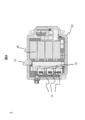
図3は、従来のインバータ2Aの内部構造を説明する図である。
インバータ2Aは、直流電力を交流電力に電力変換するためのIGBTやダイオードといったパワー半導体スイッチを実装して内蔵するパワーモジュール14(後述)と、パワーモジュール14に冷媒を流し冷却するための流路形成体12と、電力変換の際に直流電圧に発生する直流リプル電圧を平滑化するキャパシタ19と、交流電流を検知する電流センサ13Aと、ACバスバ15Aと、制御基板およびEMCフィルタ(符号なし)と、を備えている。これらのインバータ2Aの構成部品は、インバータ筐体23Aに内蔵されて3相インバータの主回路を形成している。なお、流路形成体12は、パワーモジュール14を覆うように形成されている。
インバータ2Aは、キャパシタ19とパワーモジュール14とが前述のモータ1に電気的接続をするために、ACバスバ15Aを三相分備えており、ACバスバ15Aはインバータ筐体23Aから外部に向かって出力されている。三相のACバスバ15Aは、電流センサ13Aをそれぞれ備えている。なお、インバータ筐体23Aからは、ACバスバ15A以外に直流コネクタ(符号なし)も出力されている。
電流センサ13Aは、ベクトル制御を行うために、モータ1の3相の交流電流値をそれぞれ検出して、モータコントローラ(図示せず)にフィードバックしている。また、電流センサ13Aには、所定の耐熱許容温度の閾値があるため、電流センサ13Aはその温度の閾値を超えるような高温環境で動作すると、検出誤差が発生する。なお、所定の耐熱許容温度は、例えば125℃である。
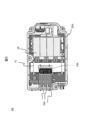
図4は、本発明の一実施形態に係るインバータ2の内部構造を説明する図である。
電流センサ13は、ACバスバ15を周方向で囲むように形成され、ACバスバ15との間に絶縁性の樹脂を設けている。これにより、電流センサ13は、ACバスバ15とは接触しない非接触型の電流センサ13となっている。
インバータ2は、従来のインバータ2Aに比べて、ACバスバ15をインバータ2に沿って延材させることなく、インバータ2の下部方向(紙面奥側)であるモータ1方向へ延材させている。そのため、インバータ筐体23の体積は、従来のインバータ筐体23Aに比べて、ACバスバ15を延材しない分、体積が小さくなっている。
またこれに伴い、電流センサ13も流路形成体12の上部(紙面手前側)に設置することなく、ACバスバ15の延材方向に合わせて、インバータ2とモータ1との間に設置することができる。より具体的には、電流センサ13は、インバータ筐体23において、流路形成体12の設置面を介して反対側の面に設置されている。このため、インバータ2の小型化と低背化を実現できている。
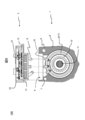
図5は、図1のインバータ一体型モータ100のB-B断面図である。
モータ1は、ロータ10とステータ(ステータコア)17とがモータハウジング8に収納されている構成である。ロータ10は回転軸11を有しており、ギアボックス3の入力側の軸と接続されてトルクを伝達している。ステータコア17の内側をロータ10が回転し、ステータコア17の軸方向周囲に形成されたコイルにより、モータ1に電力が供給されている。
ステータコア17に形成されているコイルには、コイルの端部であるコイルエンド9が形成されている。コイルエンド9からは、インバータ2と接続するためのモータケーブル16が出力されている。
電流センサ収納部4は、モータハウジング8内で、ロータ10とステータ17と回転軸11とを除いた空間を利用して設けられている。インバータ2は、モータ1に結合する際に、電流センサ13の取り付部分がモータ1に設けられている電流センサ収納部4に嵌合されるように、固定される。これにより、電流センサ収納部4は、電流センサ13をモータ1のモータハウジング8内に収納させる。
ここで、電流センサ13は、パワーモジュール14の流路形成体12に冷却される必要があるため、モータハウジング8内のコイルエンド9と流路形成体12との間に挟まれる位置に配置される。そうすることで、電流センサ13の少なくとも一部がモータハウジング8内に収納され、高密度実装化され、固定性も高めることができる。
パワーモジュール14と流路形成体12は、電流センサ13を間に挟んで、モータ回転軸11と対向の位置関係となっている。そうすることで、モータ1とインバータ2との間の交流配線である前述のACバスバ15の配線の長さが短くなる。これにより、インバータ一体型モータ100の小型化・低背化を実現している。
以上をまとめると、パワーモジュール14は、ステータ17及びロータ10を介してモータ1の回転軸11と対向する位置に配置されている。また、電流センサ13は、回転軸11の垂直方向から見た場合、流路形成体12とステータ17のコイルエンド9との間に配置されている。これにより、電流センサ13の少なくとも一部がモータハウジング8内に収納されている。
モータ1の流路について説明する。モータ1は、前述したモータ流路入口6から装置全体を冷却するための冷媒を流入させ、一続きの流路である流路形成体12およびモータ流路18に冷媒を流している。つまり、モータ流路18内を流れる冷媒は、インバータ2に内蔵されるパワーモジュール14を冷却するための流路形成体12にも流れており、モータ1とインバータ2で冷媒が共有されている。流路形成体12とモータ流路18とを流れた冷媒は、前述したモータ流路出口7からインバータ一体型モータ100の外へ排出される。このような冷媒流通構造により、モータ1およびインバータ2の冷却が可能となる。
パワーモジュール14を冷却する流路形成体12により、電流センサ13とその周辺の空間の空気層とを冷却し、電流センサ13を冷却することができる。よって、モータハウジング8内が電流センサ13の耐熱温度以上の高温環境であっても、配置された電流センサ13はモータ流路18内を流れる冷媒によって冷却され、電流センサ13の温度を所定の許容耐熱温度よりも低い温度に維持できる。そうすることで、電流センサ13の検出誤差の低減と信頼性向上が可能となる。なお、冷媒の温度は例えば、70℃以下である。
また、上記の構成により、インバータ2に配置されているキャパシタ19も、流路形成体12からの冷却効果だけでなく、モータハウジング8からインバータ筐体23を介して間接的に冷却されることで、冷却性能を向上させている。これにより、インバータ一体型モータ100は、高精度・高信頼に動作可能としている。
これにより、インバータ2はインバータ筐体23を延材させて、電流センサ13やACバスバ15を配置する必要がなくなる。また、電流センサ収納部4はその内壁が、インバータ2の流路形成体12やモータ流路18に近接しているため、周囲の内壁に対しての熱移動を行うことが可能になる構造である。そのため、インバータ2の小型化を実現するだけでなく、冷却性能も向上させたインバータ一体モータ100を実現できている。
図6は、図1のインバータ一体型モータ100のA-A断面図である。
ACバスバ15は、中央部分に穴が形成されている電流センサ13を貫通しており、貫通部分は絶縁性の樹脂を介している。これにより、電流センサ13は非接触型のセンサになっている。また、インバータ2とモータ1は一体化される際に、ACバスバ15は、電流センサ13が電流センサ収納部4に収納された際に、モータ1が有するモータケーブル16と接続される。これにより、電流センサ13と交流バスバ15の位置決め性を、電流センサ収納部4が向上させている。
このとき、モータ流路18と流路形成体12の流路も接続され、前述したようにそれぞれの流路の内部を流れる冷媒が共有される。これにより、電流センサ13と流路形成体12の間の熱抵抗を低減できている。
このような構成により、インバータ2のACバスバ15と、モータケーブル16で構成される接続配線長を大幅に短縮し、インバータ2の体積も削減可能としている。また、電流センサ13を流路形成体12の面だけでなくモータ流路18によっても冷却し、高温環境なモータハウジング8の内部でも、高精度・高信頼に動作可能とし、センシング精度と信頼性を確保できる。
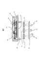
図7は、図4のインバータ2とモータ1との接合部分を説明する図である。
電流センサ13は、ACバスバ15に対応する三相電流分が電流センサ取付部20に取付けられ、電流センサ冷却面21に電流センサ13の少なくとも一部が接触及び固定されている。これにより、電流センサ13が流路形成体12で冷却され、電流センサ13の温度を所定の許容温度以下に保つことができる。
電流センサ取付部20は、インバータ筐体23において流路形成体12と反対の面に設けられ、電流センサ13を取り付けている。また、電流センサの固定性を高めるため電流センサ取付部20を蓋体22によって、封止されている。
蓋体22は、パワーモジュールと接続しているACバスバ15が貫通し、ACバスバー15はモータと接続されている。また、前述したように、電流センサ取付部20は、インバータ2とモータ1を一体にする際に、モータハウジング8に形成され電流センサ13を収納するための収納部4と嵌合される。
このような構成により、モータ1の内部の高温環境やギアボックス3内のギアのオイルから、電流センサ13を熱的に保護している。なお、電流センサ13は、コアレス型のセンサを用いることもできる。その場合、センスICとシールド部材を冷却する必要がある。このコアレスセンサも基本的に非接触型のセンサであり、インバータ2のACバスバ15に連携して配置される。
以上説明した本発明の第1の実施形態によれば、以下の作用効果を奏する。
(1)インバータ一体型モータ100は、直流電流を交流電流に変換するパワーモジュール14と、パワーモジュール14に冷媒を流し、かつパワーモジュール14を覆うように形成される流路形成体12と、パワーモジュール14と流路形成体12とを内部に設置するインバータ2と、交流電流を検知する電流センサ13と、ステータ17及びロータ10を収納するモータハウジング8によって構成されるモータ1と、を備え、パワーモジュール14は、ステータ17及びロータ10を介してモータ1の回転軸11と対向する位置に配置され、電流センサ13は、回転軸11の垂直方向から見た場合、流路形成体12とステータ17のコイルエンド9との間に配置され、かつ電流センサ13の少なくとも一部がモータハウジング8内に収納される。このようにしたので、インバータ2の冷却性能と小型化とを両立したインバータ一体型モータ100を提供できる。
(2)インバータ一体型モータ100の電流センサ13は、インバータ2の筐体23において、流路形成体12の設置面を介して反対側の面に設置される。このようにしたので、インバータ2を小型化する。
(3)インバータ一体型モータ100の電流センサ13は、インバータ2の筐体23に形成され電流センサ13を取付けるための取付部20に設置され、取付部20は、インバータ2とモータ1を一体にする際に、モータハウジング8に形成され電流センサを収納するための収納部4と嵌合される。このようにしたので、電流センサ13の固定性を高めつつ、インバータ一体型モータ100の小型化に貢献している。
(4)インバータ一体型モータ100は、取付部20は蓋体22によって封止され、パワーモジュール14と接続している交流バスバ15は、蓋体22を貫通してモータ1と接続される。このようにしたので、電流センサ13の固定性を高めている。
(5)インバータ一体型モータ100は、電流センサ13は、交流バスバ15とは接触しない。このようにしたので、非接触型を採用しながら、電流センサ13の配置に必要なスペースを削減できる。
(6)インバータ一体型モータ100は、電流センサ13は、コアレス電流センサである。このようにしたので、電流センサの他のタイプを採用しても、同様の効果を得ることができる。
なお、以上の説明はあくまでも一例であり、発明を解釈する際、上記実施の形態の記載事項と特許請求の範囲の記載事項の対応関係に何ら限定も拘束もされない。また、発明の技術的思想を逸脱しない範囲で、削除・他の構成に置換・他の構成の追加をすることが可能であり、その態様も本発明の範囲内に含まれる。
100…インバータ一体型モータ、1…モータ、2…インバータ、3…ギアボックス、4…電流センサ収納部、5…固定部、6…モータ流路入口、7…モータ流路出口、8…モータハウジング、9…コイルエンド、10…ロータ、11…回転軸、12…流路形成体、13、13A…電流センサ、14…パワーモジュール、15,15A…AC(交流)バスバ、16…モータケーブル、17…ステータ(ステータコア)、18…モータ流路、19…キャパシタ、20…電流センサ取付部、21…電流センサ冷却面、22…電流センサ収納室の蓋体、23、23A…インバータ筐体、24…インバータ搭載面
Claims (6)
- 直流電流を交流電流に変換するパワーモジュールと、
前記パワーモジュールに冷媒を流し、かつ前記パワーモジュールを覆うように形成される流路形成体と、
前記パワーモジュールと前記流路形成体とを内部に設置するインバータと、
前記交流電流を検知する電流センサと、 ステータ及びロータを有するモータと、
前記ステータ及び前記ロータを収納するモータハウジングと、を備え、
前記パワーモジュールは、前記ステータ及び前記ロータを介して前記モータの回転軸と対向する位置に配置され、
前記電流センサは、前記回転軸の垂直方向から見た場合、前記流路形成体と前記ステータのコイルエンドとの間に配置され、かつ前記電流センサの少なくとも一部が前記モータハウジング内に収納される
インバータ一体型モータ。 - 請求項1に記載のインバータ一体型モータであって、
前記電流センサは、前記インバータの筐体において、前記流路形成体の設置面を介して反対側の面に設置される インバータ一体型モータ。 - 請求項2に記載のインバータ一体型モータであって、
前記電流センサは、前記インバータの筐体に形成された取付部に設置され、
前記取付部は、前記インバータと前記モータを一体にする際に、前記モータハウジングに形成された電流センサを収納するための収納部と嵌合される
インバータ一体型モータ。 - 請求項3に記載のインバータ一体型モータであって、
前記取付部は蓋体によって封止され、
前記パワーモジュールと接続している交流バスバは、前記蓋体を貫通して前記モータと接続される インバータ一体型モータ。 - 請求項4に記載のインバータ一体型モータであって、
前記電流センサは、前記交流バスバとは接触しない
インバータ一体型モータ。 - 請求項5に記載のインバータ一体型モータであって、
前記電流センサは、コアレス電流センサである
インバータ一体型モータ。
Priority Applications (2)
| Application Number | Priority Date | Filing Date | Title |
|---|---|---|---|
| US17/922,850 US12316171B2 (en) | 2020-05-19 | 2021-01-29 | Inverter integrated motor |
| CN202180031363.XA CN115461967B (zh) | 2020-05-19 | 2021-01-29 | 逆变器一体型电动机 |
Applications Claiming Priority (2)
| Application Number | Priority Date | Filing Date | Title |
|---|---|---|---|
| JP2020087753A JP7381403B2 (ja) | 2020-05-19 | 2020-05-19 | インバータ一体型モータ |
| JP2020-087753 | 2020-05-19 |
Publications (1)
| Publication Number | Publication Date |
|---|---|
| WO2021235009A1 true WO2021235009A1 (ja) | 2021-11-25 |
Family
ID=78606847
Family Applications (1)
| Application Number | Title | Priority Date | Filing Date |
|---|---|---|---|
| PCT/JP2021/003173 Ceased WO2021235009A1 (ja) | 2020-05-19 | 2021-01-29 | インバータ一体型モータ |
Country Status (4)
| Country | Link |
|---|---|
| US (1) | US12316171B2 (ja) |
| JP (1) | JP7381403B2 (ja) |
| CN (1) | CN115461967B (ja) |
| WO (1) | WO2021235009A1 (ja) |
Cited By (2)
| Publication number | Priority date | Publication date | Assignee | Title |
|---|---|---|---|---|
| EP4297252A1 (en) * | 2022-06-20 | 2023-12-27 | Valeo eAutomotive Germany GmbH | Electric drive assembly system, vehicle and assembly method of electric drive assembly system |
| EP4545471A4 (en) * | 2022-06-24 | 2026-06-24 | Tadano Ltd | CRANE |
Families Citing this family (4)
| Publication number | Priority date | Publication date | Assignee | Title |
|---|---|---|---|---|
| JP2023110968A (ja) * | 2022-01-31 | 2023-08-10 | 三菱電機株式会社 | 回転電機ユニット |
| JPWO2025109695A1 (ja) * | 2023-11-21 | 2025-05-30 | ||
| JP2025126060A (ja) * | 2024-02-16 | 2025-08-28 | Astemo株式会社 | 電力変換装置 |
| JPWO2025238689A1 (ja) * | 2024-05-13 | 2025-11-20 |
Citations (3)
| Publication number | Priority date | Publication date | Assignee | Title |
|---|---|---|---|---|
| JP2012147564A (ja) * | 2011-01-12 | 2012-08-02 | Hitachi Automotive Systems Ltd | 回転電機ユニット |
| WO2013118670A1 (ja) * | 2012-02-06 | 2013-08-15 | 三菱電機株式会社 | 機電一体モジュール |
| JP2019198175A (ja) * | 2018-05-09 | 2019-11-14 | 日産自動車株式会社 | 電力変換装置の冷却システム |
Family Cites Families (5)
| Publication number | Priority date | Publication date | Assignee | Title |
|---|---|---|---|---|
| JP4441338B2 (ja) * | 2004-06-18 | 2010-03-31 | 本田技研工業株式会社 | 回転機 |
| JP4339832B2 (ja) * | 2005-08-11 | 2009-10-07 | 三菱電機株式会社 | 車両用回転電機 |
| JP5409517B2 (ja) | 2010-05-31 | 2014-02-05 | 日立オートモティブシステムズ株式会社 | 電気回路装置 |
| JP6327174B2 (ja) * | 2015-02-20 | 2018-05-23 | 株式会社安川電機 | 駆動装置 |
| US11239761B2 (en) * | 2018-01-24 | 2022-02-01 | Infineon Technologies Ag | Coreless current sensor for high current power module |
-
2020
- 2020-05-19 JP JP2020087753A patent/JP7381403B2/ja active Active
-
2021
- 2021-01-29 US US17/922,850 patent/US12316171B2/en active Active
- 2021-01-29 WO PCT/JP2021/003173 patent/WO2021235009A1/ja not_active Ceased
- 2021-01-29 CN CN202180031363.XA patent/CN115461967B/zh active Active
Patent Citations (3)
| Publication number | Priority date | Publication date | Assignee | Title |
|---|---|---|---|---|
| JP2012147564A (ja) * | 2011-01-12 | 2012-08-02 | Hitachi Automotive Systems Ltd | 回転電機ユニット |
| WO2013118670A1 (ja) * | 2012-02-06 | 2013-08-15 | 三菱電機株式会社 | 機電一体モジュール |
| JP2019198175A (ja) * | 2018-05-09 | 2019-11-14 | 日産自動車株式会社 | 電力変換装置の冷却システム |
Cited By (2)
| Publication number | Priority date | Publication date | Assignee | Title |
|---|---|---|---|---|
| EP4297252A1 (en) * | 2022-06-20 | 2023-12-27 | Valeo eAutomotive Germany GmbH | Electric drive assembly system, vehicle and assembly method of electric drive assembly system |
| EP4545471A4 (en) * | 2022-06-24 | 2026-06-24 | Tadano Ltd | CRANE |
Also Published As
| Publication number | Publication date |
|---|---|
| US12316171B2 (en) | 2025-05-27 |
| JP2021182827A (ja) | 2021-11-25 |
| CN115461967B (zh) | 2026-04-03 |
| US20230155456A1 (en) | 2023-05-18 |
| CN115461967A (zh) | 2022-12-09 |
| JP7381403B2 (ja) | 2023-11-15 |
Similar Documents
| Publication | Publication Date | Title |
|---|---|---|
| JP7381403B2 (ja) | インバータ一体型モータ | |
| CN107921995B (zh) | 电动驱动装置及电动助力转向装置 | |
| EP2287467B1 (en) | Inverter-integrated electrically-powered compressor | |
| KR101260577B1 (ko) | 전동 파워 스티어링 장치, 및 제어 장치 일체형 전동기 | |
| CN107921998B (zh) | 电动驱动装置及电动助力转向装置 | |
| CN104584408B (zh) | 电力转换装置 | |
| JP6621491B2 (ja) | 回転電機 | |
| CN111717274A (zh) | 电动驱动装置 | |
| JP6854936B1 (ja) | 回転電機 | |
| US12445021B2 (en) | Inverter-integrated rotating electrical machine that efficiently cools a smoothing capacitor | |
| US10263495B2 (en) | Rotary electric machine | |
| WO2022149366A1 (ja) | 電力変換装置 | |
| US6571895B2 (en) | Electrical machine, and a drive arrangement for a vehicle | |
| CN110710087A (zh) | 电动驱动装置及电动动力转向装置 | |
| JP6393745B2 (ja) | 電力変換装置 | |
| JP6207650B2 (ja) | 回転電機 | |
| JP5622659B2 (ja) | 電力変換装置 | |
| CN118489203B (zh) | 旋转机 | |
| US12556062B2 (en) | Vehicle drive device | |
| JP7580293B2 (ja) | モータユニット | |
| JP6364384B2 (ja) | 電力変換装置 | |
| JP2018148794A (ja) | 電力変換装置 | |
| CN112385123A (zh) | 旋转电机 | |
| WO2026033678A1 (ja) | 駆動装置 | |
| JP2021166441A (ja) | 変換回路付き駆動装置 |
Legal Events
| Date | Code | Title | Description |
|---|---|---|---|
| 121 | Ep: the epo has been informed by wipo that ep was designated in this application |
Ref document number: 21807983 Country of ref document: EP Kind code of ref document: A1 |
|
| NENP | Non-entry into the national phase |
Ref country code: DE |
|
| 122 | Ep: pct application non-entry in european phase |
Ref document number: 21807983 Country of ref document: EP Kind code of ref document: A1 |
|
| WWG | Wipo information: grant in national office |
Ref document number: 17922850 Country of ref document: US |