WO2021234933A1 - 通信装置、通信方法、通信システム及びプログラム - Google Patents
通信装置、通信方法、通信システム及びプログラム Download PDFInfo
- Publication number
- WO2021234933A1 WO2021234933A1 PCT/JP2020/020232 JP2020020232W WO2021234933A1 WO 2021234933 A1 WO2021234933 A1 WO 2021234933A1 JP 2020020232 W JP2020020232 W JP 2020020232W WO 2021234933 A1 WO2021234933 A1 WO 2021234933A1
- Authority
- WO
- WIPO (PCT)
- Prior art keywords
- fdb
- unit
- accommodation
- signal
- relay network
- Prior art date
- Legal status (The legal status is an assumption and is not a legal conclusion. Google has not performed a legal analysis and makes no representation as to the accuracy of the status listed.)
- Ceased
Links
Images





Classifications
-
- H—ELECTRICITY
- H04—ELECTRIC COMMUNICATION TECHNIQUE
- H04L—TRANSMISSION OF DIGITAL INFORMATION, e.g. TELEGRAPHIC COMMUNICATION
- H04L45/00—Routing or path finding of packets in data switching networks
- H04L45/02—Topology update or discovery
-
- H—ELECTRICITY
- H04—ELECTRIC COMMUNICATION TECHNIQUE
- H04L—TRANSMISSION OF DIGITAL INFORMATION, e.g. TELEGRAPHIC COMMUNICATION
- H04L12/00—Data switching networks
- H04L12/28—Data switching networks characterised by path configuration, e.g. LAN [Local Area Networks] or WAN [Wide Area Networks]
- H04L12/40—Bus networks
-
- H—ELECTRICITY
- H04—ELECTRIC COMMUNICATION TECHNIQUE
- H04L—TRANSMISSION OF DIGITAL INFORMATION, e.g. TELEGRAPHIC COMMUNICATION
- H04L45/00—Routing or path finding of packets in data switching networks
- H04L45/66—Layer 2 routing, e.g. in Ethernet based MAN's
Definitions
- the present invention relates to an FDB update technique in an L2 network.
- L2NW Layer 2 network
- FDB Forwarding Database
- Frames continue to be sent to the port before the accommodation change, and downlink frames cannot be received at the base after the accommodation change.
- SW Switch
- the FDB of the relay switch hereinafter referred to as SW (Switch)
- SW switch
- the aging time of the relay SW is waited for, and the accommodation is changed. Measures were taken such as sending a user frame from the base to each base to update the FDB.
- the SW that requires the flash increases with the scale of the L2NW, and the impact on other users also increases due to flooding.
- the aging time may be interrupted for a long time. To send a user frame from the base after the accommodation change, it is necessary to enter the user base, which is not completed only by the work of the telecommunications carrier.
- the MAC (Media Access Control) address of the device in which the accommodation SW before the accommodation change and the accommodation SW after the change are connected (for example, a logical connection is also possible) and held by the accommodation SW before the change
- the VLAN (Virtual Local Area Network) ID and the like are transmitted to the changed accommodation SW, and the changed accommodation SW broadcasts a control frame with a VLAN ID tag using the received MAC address as the source address to the network.
- the communication device of the present disclosure is A signal receiver that receives signals and A signal transmitter that transmits signals and A frame generator that generates a control frame for updating the FDB of the relay network based on the FDB (Forwarding Database) of the device connected to the relay network. Equipped with The signal transmission unit is characterized in that the control frame generated by the frame generation unit is transmitted to each device connected to the relay network.
- the communication method of the present disclosure is:
- the frame generator generates a control frame for updating the FDB of the relay network based on the FDB (Forwarding Database) of the device connected to the relay network.
- the signal transmission unit is characterized in that the control frame generated by the frame generation unit is transmitted to each device connected to the relay network.
- the system of the present disclosure is a system in which a device installed outside the communication device executes at least a part of the functions provided in the communication device according to the present disclosure.
- the system of the present disclosure is a communication system in which a plurality of accommodation switches are communicated and connected to the relay network, and at least one of the plurality of accommodation switches functions as a communication device according to the present disclosure. It is a system.
- the program of the present disclosure is a program for realizing a computer as each functional unit provided in the communication device according to the present disclosure, and each step provided in the communication method executed by the communication device according to the present disclosure is performed by the computer. It is a program to be executed by.
- each SW can update the FDB by receiving the control frame, the flash of the FDB becomes unnecessary, and communication is possible in the device after the accommodation change without waiting for the aging time to elapse. It becomes.
- the schematic structure of the present disclosure is shown.
- An example of the control frame generated by this system is shown.
- An example of the port configuration of the accommodation SW91 is shown.
- An example of the configuration of the accommodation SW of the first embodiment is shown.
- the procedure of FDB update in the first embodiment is shown.
- An example of the configuration of the accommodation SW of the second embodiment is shown.
- the procedure of FDB update in the second embodiment is shown.
- An example of creating an FDB list is shown.
- An example of the configuration of the accommodation SW of the third embodiment is shown.
- the procedure of FDB update in the third embodiment is shown.
- the procedure for updating the FDB in the fourth embodiment is shown.
- An example of the flow chart of the accommodation SW in the 4th embodiment is shown.
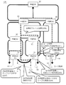
- FIG. 1 shows the system configuration of the present disclosure.
- the present disclosure is an L2 network system in which a plurality of accommodation SW91s are communication-connected to a relay SW92. At least one of the plurality of accommodation SW91s functions as the communication device of the present disclosure. Further, the L2 network system is referred to as a relay network.
- the accommodation SW91 includes an access port connected to the user base 93 and a relay port connected to the relay SW92.
- the FDB is updated without performing the FDB Flush of the accommodation SW91 and the relay SW92.
- the accommodation SW91 has a function of holding a record of FDB for each port for a certain period of time. Further, the accommodation SW91 has a function of frame-transmitting the set of the MAC address and the VLAN recorded in the FDB as the source MAC address and the VLAN.
- the accommodation SW91 # 2 before the change is connected to the accommodation SW91 # 1 after the change, and broadcast communication is performed using the above function. This makes it possible to update the FDB with all the relay SW92 and the accommodation SW91 on the network belonging to the corresponding VLAN. When the VLAN is not used, the accommodation SW91 may perform broadcast communication using the MAC address recorded in the FDB as the source MAC address.
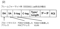
- FIG. 2 shows an example of a control frame generated by this system.
- the frame format shown in FIG. 2 shows the case of the IEEE802.1ad format.
- the frame format is not limited to this, and any frame format corresponding to the L2 network system can be used.
- FIG. 3 shows an example of the port configuration of the accommodation SW91.
- the access port 21-1 is not connected to the user base 93, the access port 21-2 is connected to the user base 93, and the relay port 22 is connected to the relay SW92.
- the accommodation SW91 of this system has a function of transmitting the generated control frame from the relay port 22 to the network. Further, transmission is possible from the access port 21-1 and the relay port 22 other than the access port 21-2 that accommodates the user base 93.
- the present disclosure is also applicable to changing the transfer destination of an encapsulated frame such as IEEE 802.1ah.
- FIG. 4 shows a configuration example of the accommodation SW of the present embodiment.
- the accommodation SW91 of the present embodiment includes a signal receiving unit 11, a signal transmitting unit 12, an FDB 13, and a frame generating unit 14.
- the accommodation SW91 of the present embodiment can also be realized by a computer and a program, and the program can be recorded on a recording medium or provided through a network. The same applies to the following embodiments.
- the signal receiving unit 11 is an interface for receiving an input signal from the outside.
- the signal transmission unit 12 is a functional unit that transmits a frame to the outside as an output signal.
- the FDB 13 is a functional unit that holds a forwarding table of the apparatus, and holds information about a source MAC address, a VLAN, and a received port for a frame received by the signal receiving unit 11 as a set.
- the frame generation unit 14 is a functional unit that reads out the FDB and generates a control frame. The control frame is transmitted from the signal transmission unit 12.
- the signal receiving unit 11, the signal transmitting unit 12, and the FDB 13 are the same functional units as those in the prior art. The detailed operation of the frame generation unit 14 will be described below.
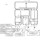
- FIG. 5 shows a procedure for updating the FDB in the present embodiment.
- -S101 Remove the cable for the user-based 93 points connected to the accommodation SW91 # 2 before the accommodation change.
- S102 Connect the ports before and after the accommodation change with a cable, and establish a communication path between the accommodation SW91 # 2 and 91 # 1.
- the access port of the accommodation SW91 # 1 and the access port of the accommodation SW91 # 2 are connected by communication.
- the connections of the accommodation SW91 # 1 and 91 # 2 are not limited to physical connections, but logical connections are also possible.
- a control frame is created by using the set of the MAC address and the VLAN of the FDB entry for the corresponding port as the source MAC address and the VLAN.
- the signal transmission unit 12 provided in the accommodation SW91 # 2 broadcasts the created control frame from the communication path connected in step S102.
- the control frame is transmitted to the accommodation SW91 # 1 and transferred from the accommodation SW91 # 1 to each relay SW92.
- the FDB can be updated by all the relay SW92 and the accommodation SW91 on the network belonging to the corresponding VLAN.
- S104 The cable between the accommodation SW91 is removed from the access port of the accommodation SW91 # 1 after the accommodation change, and the cable is connected to the user base 93.
- the control frame may not be transmitted by the accommodation SW91 # 2, but may be transmitted by the accommodation SW91 # 1 after the accommodation is changed.
- the accommodation SW91 # 1 receives the command transmission from the accommodation SW # 2 before the accommodation change, and the frame generation unit 14 provided in the accommodation SW91 # 1 creates a control frame.
- FIG. 6 shows a configuration example of the accommodation SW of the second embodiment.
- the accommodation SW91 of the present embodiment includes a signal receiving unit 11, a signal transmitting unit 12, an FDB 13, an FDB list creating unit 15, and a frame generating unit 14.
- the signal receiving unit 11 is an interface for receiving an input signal from the outside.
- the signal transmission unit 12 is a functional unit that transmits a frame to the outside as an output signal.
- the FDB 13 is a functional unit that holds a forwarding table.
- the FDB list creation unit 15 is a functional unit that reads the FDB, creates / updates the FDB list, and holds the FDB list.
- the frame generation unit 14 is a functional unit that reads the FDB list created by the FDB list creation unit 15 and generates a control frame.
- the control frame is transmitted from the signal transmission unit 12.
- the signal receiving unit 11, the signal transmitting unit 12, and the FDB 13 are the same functional units as those in the prior art. The detailed operations of the FDB list creation unit 15 and the frame generation unit 14 will be described below.
- the feature of the second embodiment is that it has an FDB list creating unit 15. It is assumed that various relay SWs exist in the L2 network, the MAC address information held by the relay SWs is different, and the aging time set for each relay SW92 is also different. Therefore, although the information has been deleted from the FDB of the user accommodation SW91 due to the excess of the aging time, there is a possibility that the information is retained in the FDB of any relay SW92 in the L2 network. In order to avoid such a problem, the FDB list creation unit 15 creates an FDB list that holds information about the FDB for the longest aging time among the SWs in the L2 network.
- FIG. 7 shows a procedure for updating the FDB of the present embodiment.
- S201 In the accommodation SW91 # 2 before the accommodation change, the FDB list creation unit 15 periodically acquires and records the FDB held by the FDB 13.
- S202 Stops communication to the accommodation SW91 # 2 accommodating the corresponding user base 93. For example, the path is abolished, the cable is removed, the device at the user base 93 is removed, and the like. Since then, there has been no FDB update addressed to the accommodation change base on the L2 network.
- S203 In the accommodation SW91 # 2 before the accommodation change, the FDB list creation unit 15 reads the latest FDB held by the FDB 13 and merges it with the recorded FDB to create an FDB list.
- -S204 Remove the cable for the user base connected to the accommodation SW91 # 2 before the accommodation change.
- S205 Connect the access ports of the accommodation SW91 # 1 and 91 # 2 before and after the accommodation change with a cable, and establish a communication path between the accommodation SW91.
- the signal transmission unit 12 transmits the created control frame by broadcasting. This makes it possible to update the FDB with all the relay SW92 and the accommodation SW91 on the network belonging to the corresponding VLAN.
- S207 The cable between the accommodation SW91 is removed from the access port of the accommodation SW91 # 1 after the accommodation change, and the cable is connected to the user base 93.
- the device to which the present disclosure is applied has the following functions in addition to the basic functions of L2SW.
- - obtain FDB information on a regular basis.
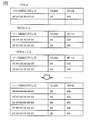
- the FDB list creation unit 15 acquires FDB information at time A, time A + ⁇ , and time A + 2 ⁇ , as shown in FIG.
- the FDB list creation unit 15 merges the acquired FDB information to create and retain the FDB list with which communication has been performed for a certain period of time.
- FIG. 9 shows a configuration example of the accommodation SW of the third embodiment.
- the accommodation SW91 of the present embodiment includes a signal receiving unit 11, a signal transmitting unit 12, a signal distribution unit 16, a signal discarding unit 17, an FDB 13, an FDB list creating unit 15, and a frame generating unit 14.
- the signal receiving unit 11 is an interface for receiving an input signal from the outside.
- the signal transmission unit 12 is a functional unit that transmits a frame to the outside as an output signal.
- the signal distribution unit 16 is a functional unit that distributes the control frame for updating the FDB among the input signals from the outside to the signal disposal unit 17.
- the signal discarding unit 17 is a functional unit that discards the control frame for updating the FDB.
- the FDB 13 is a functional unit that holds a forwarding table of the apparatus.
- the FDB list creation unit 15 is a functional unit that reads the FDB and updates and holds the FDB list.
- the frame generation unit 14 is a functional unit that generates a control frame for reading and transmitting an FDB list.
- the functions and operations of the signal receiving unit 11, the signal transmitting unit 12, the FDB 13, the FDB list creating unit 15, and the frame generating unit 14 are the same functional units as those in the second embodiment. The detailed operation of the signal distribution unit 16 and the signal disposal unit 17 will be described below.
- the signal distribution unit 16 of this system has a filtering function because the control frame for updating the FDB is not transmitted to the user base 93.
- a filtering function because the control frame for updating the FDB is not transmitted to the user base 93.
- the function of filtering when the Type / Length value of the control frame is "0101 (Experimental)" in the accommodation SW91, it is possible to prevent the frame from reaching the user base 93.
- a method of using an OAM (Operations, Addinition, Maintenance) frame as a control frame and filtering is also conceivable.
- the filtering method is not limited to this.
- FIG. 10 shows the procedure for updating the FDB in this embodiment.
- steps S101 to S104 in the first embodiment or steps S201 to S207 in the second embodiment are executed.
- steps S103 and S206 each accommodation SW91 discards the control frame using the signal distribution section 16 and the signal discard section 17.
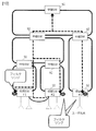
- FIG. 11 shows an example of the system configuration of the present embodiment.
- the management device 95 connected to each accommodation SW91 is provided.
- the management device 95 can use any system having an application connected to the containment SW91.
- the procedure for updating the FDB of the present embodiment will be shown with reference to FIGS. 11 and 12.
- S401 The management device 95 accesses the accommodation SW91 # 2 before the accommodation change for a certain period of time, and periodically acquires and records the FDB.
- the conditions are the same as those of the FDB list creating unit 15 described in the second embodiment, for example.
- S402 Stops communication to the accommodation SW91 # 2 accommodating the corresponding user base 93. For example, the path is abolished, the cable is removed, the device at the user base 93 is removed, and the like. Since then, there has been no FDB update addressed to the accommodation change base on the L2 network.
- S403 The management device 95 reads the latest FDB of the accommodation SW91 # 2 before the accommodation change and merges it with the recorded FDB to create an FDB list.
- -S404-1 Remove the cable for the user base connected to the accommodation SW91 # 2 before the accommodation change.
- -S404-2 Connect the cable for the user base to the access port of the accommodation SW91 # 1 after the accommodation change.
- S405 The management device 95 is connected to the accommodation SW91 # 1 after the accommodation change.
- the management device 95 creates a control frame using the set of the MAC address and the VLAN of the accommodation change target port in the FDB list as the source MAC address and the VLAN, and transmits the control frame by broadcasting. This makes it possible to update the FDB with all the relay SW92 and the accommodation SW91 on the network belonging to the corresponding VLAN.
- -S406 In the accommodation SW91 # 1 after the accommodation change, the FDB of the corresponding VLAN is deleted. For example, the cable for the management device 95 connected to the accommodation SW91 # 1 is removed.
- the management device 95 can send and receive signals to and from the accommodation SW91, and can use any means capable of creating an FDB list. Further, the arrangement of the management device 95 is arbitrary, and for example, the function of the management device 95 may be provided in the user base 93.
- the management device 95 executes all of steps S401, S402, S403, S404-1, S404-2, S405, and S406, but any device connected to the accommodation SW91 may be used. You may perform any of these steps.
- the accommodation SW91 # 2 before the accommodation change may execute the communication stop (S402), or the terminal of the user base 93 or the accommodation SW91 # 1 after the accommodation change executes the transmission of the control frame (S405). You may.
- the signal receiving unit 11, the signal transmitting unit 12, the FDB 13, the frame generation unit 14, the FDB list creating unit 15, the signal distribution unit 16, and the signal discarding unit 17 are all included.
- the accommodation SW91 which is a communication device is shown, the present disclosure is not limited to this.
- at least a part of the functions provided in the accommodation SW91 may be executed by a device installed outside the accommodation SW91, such as the management device 95 provided in the fourth embodiment.
- This disclosure can be applied to the information and communication industry.
- Signal receiving unit 12 Signal transmitting unit 13: FDB 14: Frame generation unit 15: FDB list creation unit 16: Signal distribution unit 17: Signal disposal unit 91: Accommodation switch 92: Relay switch 93: User base 95: Management device
Landscapes
- Engineering & Computer Science (AREA)
- Computer Networks & Wireless Communication (AREA)
- Signal Processing (AREA)
- Small-Scale Networks (AREA)
Abstract
FDBのフラッシュはユーザの拠点数に伴ってフラッシュが必要となるSWが増加し、フラッディングにより他ユーザへの影響も大きくなる。エイジングタイムの経過はネットワーク仕様や装置設定によって、長時間の通信断が発生する。収容変更後の拠点からユーザフレームの送信には、ユーザ拠点へ入る必要があり通信事業者側の作業のみで完結しない。 本開示は、信号を受信する信号受信部と、信号を送信する信号送信部と、中継網に接続されている装置のFDB(Forwarding DataBase)を基にして、前記中継網のFDBを更新するための制御フレームを生成するフレーム生成部と、を備え、前記信号送信部は、前記フレーム生成部で生成された制御フレームを、前記中継網に接続されている各装置に送信することを特徴とする通信装置である。
Description
本発明は、L2ネットワークにおけるFDB更新技術に関する。
レイヤ2(以下、L2と称する。)ネットワーク(以下、L2NWと表記する場合がある。)において、ユーザ拠点の収容を変更する場合、FDB(Forwarding DataBase)に収容変更前の記録が残っていると収容変更前のポートへフレームを送信し続け、収容変更後の拠点では下りフレームを受信することができない。FDB更新し、下りフレームを受信できるようにするために、中継するスイッチ(以下、SW(Switch)と称する。)のFDBをフラッシュする、中継するSWのエイジングタイムの経過を待つ、収容変更後の拠点から各拠点へユーザフレームを送信してFDBを更新するといった対応がとられていた。
しかし、FDBのフラッシュはL2NWの規模に伴ってフラッシュが必要となるSWが増加し、フラッディングにより他ユーザへの影響も大きくなる。エイジングタイムの経過はネットワーク仕様や装置設定によって、長時間の通信断が発生する。収容変更後の拠点からユーザフレームの送信には、ユーザ拠点へ入る必要があり通信事業者側の作業のみで完結しない。
本開示では、収容変更前の収容SWと変更後の収容SWを接続(例えば論理的な接続でも可)し、変更前の収容SWで保持している当該装置のMAC(Media Access Control)アドレス、VLAN(Virtual Local Area Network) ID等を変更後の収容SWに送信し、変更後の収容SWは、受信したMACアドレスをソースアドレスとしてVLAN IDのタグを付与した制御フレームをネットワークにブロードキャストする。
具体的には、本開示の通信装置は、
信号を受信する信号受信部と、
信号を送信する信号送信部と、
中継網に接続されている装置のFDB(Forwarding DataBase)を基にして、前記中継網のFDBを更新するための制御フレームを生成するフレーム生成部と、
を備え、
前記信号送信部は、前記フレーム生成部で生成された制御フレームを、前記中継網に接続されている各装置に送信することを特徴とする。
信号を受信する信号受信部と、
信号を送信する信号送信部と、
中継網に接続されている装置のFDB(Forwarding DataBase)を基にして、前記中継網のFDBを更新するための制御フレームを生成するフレーム生成部と、
を備え、
前記信号送信部は、前記フレーム生成部で生成された制御フレームを、前記中継網に接続されている各装置に送信することを特徴とする。
具体的には、本開示の通信方法は、
フレーム生成部が、中継網に接続されている装置のFDB(Forwarding DataBase)を基にして、中継網のFDBを更新するための制御フレームを生成し、
信号送信部が、前記フレーム生成部で生成された制御フレームを、前記中継網に接続されている各装置に送信することを特徴とする。
フレーム生成部が、中継網に接続されている装置のFDB(Forwarding DataBase)を基にして、中継網のFDBを更新するための制御フレームを生成し、
信号送信部が、前記フレーム生成部で生成された制御フレームを、前記中継網に接続されている各装置に送信することを特徴とする。
具体的には、本開示のシステムは、本開示に係る通信装置に備わる少なくとも一部の機能を、前記通信装置の外部に設置されている装置が実行する、システムである。
具体的には、本開示のシステムは、複数の収容スイッチが前記中継網と通信接続されている通信システムであって、前記複数の収容スイッチの少なくともいずれかが、本開示に係る通信装置として機能する、システムである。
具体的には、本開示のプログラムは、本開示に係る通信装置に備わる各機能部としてコンピュータを実現させるためのプログラムであり、本開示に係る通信装置が実行する通信方法に備わる各ステップをコンピュータに実行させるためのプログラムである。
本開示によれば、各SWは制御フレームの受信によりFDBの更新が可能となることから、FDBのフラッシュは不要となり、また、エイジングタイムの経過を待つことなく収容変更後の装置において通信が可能となる。また、収容変更後の拠点へ通信事業者が立ち入ることなく、収容変更作業を行うことも可能となる。
以下、本開示の実施形態について、図面を参照しながら詳細に説明する。なお、本開示は、以下に示す実施形態に限定されるものではない。これらの実施の例は例示に過ぎず、本開示は当業者の知識に基づいて種々の変更、改良を施した形態で実施することができる。なお、本明細書及び図面において符号が同じ構成要素は、相互に同一のものを示すものとする。
(発明の概要)
図1に、本開示のシステム構成を示す。本開示は、複数の収容SW91が中継SW92に通信接続されているL2ネットワークシステムである。複数の収容SW91の少なくとも一つが本開示の通信装置として機能する。またL2ネットワークシステムを中継網と称する。
図1に、本開示のシステム構成を示す。本開示は、複数の収容SW91が中継SW92に通信接続されているL2ネットワークシステムである。複数の収容SW91の少なくとも一つが本開示の通信装置として機能する。またL2ネットワークシステムを中継網と称する。
収容SW91は、ユーザ拠点93に接続されるアクセスポートと、中継SW92に接続される中継ポートと、を備える。本開示では、収容SW91及び中継SW92のFDB FlushをせずにFDB更新を行う。収容SW91は、各ポート向けのFDBの記録を一定期間保持する機能を有する。また、収容SW91はFDBに記録されたMACアドレス及びVLANの組を送信元MACアドレス及びVLANとしてフレーム送信する機能を有する。変更前の収容SW91#2を変更後の収容SW91#1に接続し、上記機能を用いてブロードキャスト通信を実施する。これにより、該当VLANに属するネットワーク上のすべての中継SW92及び収容SW91でFDBを更新することが可能となる。なお、VLANを使用しない場合は、収容SW91はFDBに記録されたMACアドレスを送信元MACアドレスとしてブロードキャスト通信を実施してもよい。
図2に、本システムで生成する制御フレーム例を示す。図2に示すフレームフォーマットは、IEEE802.1ad形式の場合を示す。
・Destination Address(DA):FF:FF:FF:FF:FF:FF
・Source Address(SA):FDBリストから取得したMACアドレス
・S-tag:FDBリストから取得したVLAN
・C-tag:任意
・Type/Length:通信事業者の定めたユニーク値
・データ:00…0(42byte分)
・FCS(Frame Check Sequence)
ただし、フレームフォーマットはこれに限るものではなく、L2ネットワークシステムに応じた任意のフレームフォーマットを用いることができる。
・Destination Address(DA):FF:FF:FF:FF:FF:FF
・Source Address(SA):FDBリストから取得したMACアドレス
・S-tag:FDBリストから取得したVLAN
・C-tag:任意
・Type/Length:通信事業者の定めたユニーク値
・データ:00…0(42byte分)
・FCS(Frame Check Sequence)
ただし、フレームフォーマットはこれに限るものではなく、L2ネットワークシステムに応じた任意のフレームフォーマットを用いることができる。
図3に、収容SW91のポート構成例を示す。アクセスポート21-1はユーザ拠点93に接続されておらず、アクセスポート21-2がユーザ拠点93に接続され、中継ポート22は中継SW92に接続されている。本システムの収容SW91は、生成した制御フレームを中継ポート22からネットワークへ送信する機能を有する。またユーザ拠点93を収容していたアクセスポート21-2以外のアクセスポート21-1及び中継ポート22からも送信可能とする。
本開示は、この構成を採用することにより、通信事業者のみで中継網のFDB更新を実施可能となる。これは、FDB Flushと比較して通信影響や、作業対象装置数を少なく抑えられる。また、本開示はIEEE802.1ahのようなカプセル化されたフレームの転送先変更にも適用可能である。
(第1の実施形態)
図4に、本実施形態の収容SWの構成例を示す。本実施形態の収容SW91は、信号受信部11と信号送信部12とFDB13とフレーム生成部14を備える。本実施形態の収容SW91はコンピュータとプログラムによっても実現でき、プログラムを記録媒体に記録することも、ネットワークを通して提供することも可能である。以下の実施形態においても同様である。
図4に、本実施形態の収容SWの構成例を示す。本実施形態の収容SW91は、信号受信部11と信号送信部12とFDB13とフレーム生成部14を備える。本実施形態の収容SW91はコンピュータとプログラムによっても実現でき、プログラムを記録媒体に記録することも、ネットワークを通して提供することも可能である。以下の実施形態においても同様である。
信号受信部11は、外部からの入力信号を受信するインタフェースである。
信号送信部12は、フレームを外部へ出力信号として送信する機能部である。
FDB13は装置のフォワーディングテーブルを保持する機能部であり、信号受信部11で受信したフレームについて送信元MACアドレス、VLAN、受信したポートに関する情報を組として保持するものである。
フレーム生成部14は、FDBを読み出し、制御フレームを生成する機能部である。制御フレームは信号送信部12から送信される。
信号受信部11、信号送信部12及びFDB13は、従来技術と同じ機能部である。
フレーム生成部14の詳細動作については、以下にて記載する。
信号送信部12は、フレームを外部へ出力信号として送信する機能部である。
FDB13は装置のフォワーディングテーブルを保持する機能部であり、信号受信部11で受信したフレームについて送信元MACアドレス、VLAN、受信したポートに関する情報を組として保持するものである。
フレーム生成部14は、FDBを読み出し、制御フレームを生成する機能部である。制御フレームは信号送信部12から送信される。
信号受信部11、信号送信部12及びFDB13は、従来技術と同じ機能部である。
フレーム生成部14の詳細動作については、以下にて記載する。
図5に、本実施形態でのFDB更新の手順を示す。
・S101:収容変更前の収容SW91#2に接続されているユーザ拠93点向けケーブルを抜去する。
・S102:収容変更前後のポートをケーブルで接続し、収容SW91#2及び91#1間の通信経路を確立する。例えば、収容SW91#1のアクセスポートと収容SW91#2のアクセスポートを通信接続する。ここで、収容SW91#1及び91#2の接続は、物理的な接続に限らず、論理的な接続でも可能である。
・S103:収容変更前の収容SW91#2において、該当ポート向けのFDBエントリのMACアドレス及びVLANの組を、送信元MACアドレス及びVLANとして制御フレームを作成する。収容SW91#2に備わる信号送信部12は、作成した制御フレームを、ステップS102で接続した通信経路からブロードキャストで送信する。制御フレームは、収容SW91#1へ送信され、収容SW91#1から各中継SW92へ転送される。これにより、収容SW91#2から取得したFDBエントリに存在するMACアドレスについて、該当VLANに属するネットワーク上のすべての中継SW92及び収容SW91でFDBを更新することが可能となる。
・S104:収容変更後の収容SW91#1のアクセスポートから収容SW91間のケーブルを抜去し、ユーザ拠点93とケーブルで接続する。
・S101:収容変更前の収容SW91#2に接続されているユーザ拠93点向けケーブルを抜去する。
・S102:収容変更前後のポートをケーブルで接続し、収容SW91#2及び91#1間の通信経路を確立する。例えば、収容SW91#1のアクセスポートと収容SW91#2のアクセスポートを通信接続する。ここで、収容SW91#1及び91#2の接続は、物理的な接続に限らず、論理的な接続でも可能である。
・S103:収容変更前の収容SW91#2において、該当ポート向けのFDBエントリのMACアドレス及びVLANの組を、送信元MACアドレス及びVLANとして制御フレームを作成する。収容SW91#2に備わる信号送信部12は、作成した制御フレームを、ステップS102で接続した通信経路からブロードキャストで送信する。制御フレームは、収容SW91#1へ送信され、収容SW91#1から各中継SW92へ転送される。これにより、収容SW91#2から取得したFDBエントリに存在するMACアドレスについて、該当VLANに属するネットワーク上のすべての中継SW92及び収容SW91でFDBを更新することが可能となる。
・S104:収容変更後の収容SW91#1のアクセスポートから収容SW91間のケーブルを抜去し、ユーザ拠点93とケーブルで接続する。
なお、ステップS103において、制御フレームは、収容SW91#2が送信せず、収容変更後の収容SW91#1が送信することも可能である。この場合、収容変更前の収容SW#2からのコマンド送信を収容SW91#1が受信し、収容SW91#1に備わるフレーム生成部14が制御フレームを作成する。
(第2の実施形態)
図6に、第2の実施形態の収容SWの構成例を示す。本実施形態の収容SW91は、信号受信部11と信号送信部12とFDB13とFDBリスト作成部15とフレーム生成部14を備える。
信号受信部11は、外部からの入力信号を受信するインタフェースである。
信号送信部12は、フレームを外部へ出力信号として送信する機能部である。
FDB13は、フォワーディングテーブルを保持する機能部である。
FDBリスト作成部15は、FDBを読み出し、FDBリストを作成・更新して保持する機能部である。
フレーム生成部14は、FDBリスト作成部15で作成されたFDBリストを読み出し、制御フレームを生成する機能部である。制御フレームは信号送信部12から送信される。
信号受信部11、信号送信部12及びFDB13は、従来技術と同じ機能部である。FDBリスト作成部15、フレーム生成部14の詳細動作については、以下にて記載する。
図6に、第2の実施形態の収容SWの構成例を示す。本実施形態の収容SW91は、信号受信部11と信号送信部12とFDB13とFDBリスト作成部15とフレーム生成部14を備える。
信号受信部11は、外部からの入力信号を受信するインタフェースである。
信号送信部12は、フレームを外部へ出力信号として送信する機能部である。
FDB13は、フォワーディングテーブルを保持する機能部である。
FDBリスト作成部15は、FDBを読み出し、FDBリストを作成・更新して保持する機能部である。
フレーム生成部14は、FDBリスト作成部15で作成されたFDBリストを読み出し、制御フレームを生成する機能部である。制御フレームは信号送信部12から送信される。
信号受信部11、信号送信部12及びFDB13は、従来技術と同じ機能部である。FDBリスト作成部15、フレーム生成部14の詳細動作については、以下にて記載する。
第2の実施形態の特徴とするところは、FDBリスト作成部15を有するところにある。L2ネットワーク内には様々な中継SWが存在し、その中継SWが保持するMACアドレス情報は異なり、また、各中継SW92に設定されるエイジングタイムも異なることが想定される。このため、エイジングタイムの超過によりユーザ収容SW91のFDBからは情報を削除してしまったが、L2ネットワーク内の任意の中継SW92のFDBには保持されているといった状態が発生する可能性がある。このような問題を回避するため、FDBリスト作成部15は、L2ネットワーク内のSWのうち最も長時間のエイジングタイムに合わせ、その時間分のFDBに関する情報を保持するFDBリストを作成する。
図7に、本実施形態のFDB更新の手順を示す。
・S201:収容変更前の収容SW91#2において、FDBリスト作成部15は、FDB13で保持しているFDBを定期的に取得し、記録する。
・S202:該当するユーザ拠点93を収容する収容SW91#2への通信を停止する。例えば、パス廃止、ケーブル抜去、ユーザ拠点93の装置撤去等である。以降、L2ネットワーク上で収容変更拠点宛のFDB更新はない。
・S203:収容変更前の収容SW91#2において、FDBリスト作成部15は、FDB13で保持している最新のFDBを読み出し、記録しているFDBとマージしてFDBリストを作成する。
・S204:収容変更前の収容SW91#2に接続されているユーザ拠点向けケーブルを抜去する。
・S205:収容変更前後の収容SW91#1及び91#2のアクセスポートをケーブルで接続し、収容SW91間の通信経路を確立する。
・S206:収容変更前の収容SW91#2において、フレーム生成部14は、FDBリストのうち該当ポート向けのMACアドレス及びVLANの組を、送信元MACアドレス及びVLANとして制御フレームを作成する。信号送信部12は、作成した制御フレームを、ブロードキャストで送信する。これにより、該当VLANに属するネットワーク上のすべての中継SW92及び収容SW91でFDBを更新することが可能となる。
・S207:収容変更後の収容SW91#1のアクセスポートから収容SW91間のケーブルを抜去し、ユーザ拠点93とケーブルで接続する。
・S201:収容変更前の収容SW91#2において、FDBリスト作成部15は、FDB13で保持しているFDBを定期的に取得し、記録する。
・S202:該当するユーザ拠点93を収容する収容SW91#2への通信を停止する。例えば、パス廃止、ケーブル抜去、ユーザ拠点93の装置撤去等である。以降、L2ネットワーク上で収容変更拠点宛のFDB更新はない。
・S203:収容変更前の収容SW91#2において、FDBリスト作成部15は、FDB13で保持している最新のFDBを読み出し、記録しているFDBとマージしてFDBリストを作成する。
・S204:収容変更前の収容SW91#2に接続されているユーザ拠点向けケーブルを抜去する。
・S205:収容変更前後の収容SW91#1及び91#2のアクセスポートをケーブルで接続し、収容SW91間の通信経路を確立する。
・S206:収容変更前の収容SW91#2において、フレーム生成部14は、FDBリストのうち該当ポート向けのMACアドレス及びVLANの組を、送信元MACアドレス及びVLANとして制御フレームを作成する。信号送信部12は、作成した制御フレームを、ブロードキャストで送信する。これにより、該当VLANに属するネットワーク上のすべての中継SW92及び収容SW91でFDBを更新することが可能となる。
・S207:収容変更後の収容SW91#1のアクセスポートから収容SW91間のケーブルを抜去し、ユーザ拠点93とケーブルで接続する。
本開示を適用した装置は、L2SWの基本的な機能に加え、下記機能を有する。
・FDB情報を定期的に取得する。例えば、FDBリスト作成部15は、図8に示すように、時刻A、時刻A+α、時刻A+2αにFDB情報を取得する。
・FDBリスト作成部15は、図8に示すように、取得したFDB情報をマージして一定期間で通信のあったFDBリストを作成し、保持する。
これらの構成により、SW毎にエイジングタイムが異なる場合、収容SW91だけでなく、中継SW92で保持されている可能性があるFDBもすべて一覧化することができる。
・FDB情報を定期的に取得する。例えば、FDBリスト作成部15は、図8に示すように、時刻A、時刻A+α、時刻A+2αにFDB情報を取得する。
・FDBリスト作成部15は、図8に示すように、取得したFDB情報をマージして一定期間で通信のあったFDBリストを作成し、保持する。
これらの構成により、SW毎にエイジングタイムが異なる場合、収容SW91だけでなく、中継SW92で保持されている可能性があるFDBもすべて一覧化することができる。
FDBを記録する間隔(=α)は、自身のエイジングタイムより短い間隔であるとする。また記録したFDBを保持する期間は、中継網に属するすべてのSWの中で最も長いエイジングタイムより長いとする。またソースMACアドレスとVLANの組が同一のデータが複数ある場合、古い方を削除して最新のデータのみ残す。
(第3の実施形態)
図9に、第3の実施形態の収容SWの構成例を示す。本実施形態の収容SW91は、信号受信部11と信号送信部12と信号振分部16と信号廃棄部17とFDB13とFDBリスト作成部15とフレーム生成部14を備える。
信号受信部11は、外部からの入力信号を受信するインタフェースである。
信号送信部12は、フレームを外部へ出力信号として送信する機能部である。
信号振分部16は、外部からの入力信号のうち、FDB更新用の制御フレームを信号廃棄部17へ振り分ける機能部である。
信号廃棄部17は、FDB更新用の制御フレームを廃棄する機能部である。
FDB13は装置のフォワーディングテーブルを保持する機能部である。
FDBリスト作成部15は、FDBを読み出し、FDBリストを更新して保持する機能部である。
フレーム生成部14は、FDBリストを読み出し、送信する制御フレームを生成する機能部である。
信号受信部11、信号送信部12、FDB13、FDBリスト作成部15、フレーム生成部14の機能及び動作は、第2の実施形態と同じ機能部である。
信号振分部16及び信号廃棄部17の詳細動作については、以下にて記載する。
図9に、第3の実施形態の収容SWの構成例を示す。本実施形態の収容SW91は、信号受信部11と信号送信部12と信号振分部16と信号廃棄部17とFDB13とFDBリスト作成部15とフレーム生成部14を備える。
信号受信部11は、外部からの入力信号を受信するインタフェースである。
信号送信部12は、フレームを外部へ出力信号として送信する機能部である。
信号振分部16は、外部からの入力信号のうち、FDB更新用の制御フレームを信号廃棄部17へ振り分ける機能部である。
信号廃棄部17は、FDB更新用の制御フレームを廃棄する機能部である。
FDB13は装置のフォワーディングテーブルを保持する機能部である。
FDBリスト作成部15は、FDBを読み出し、FDBリストを更新して保持する機能部である。
フレーム生成部14は、FDBリストを読み出し、送信する制御フレームを生成する機能部である。
信号受信部11、信号送信部12、FDB13、FDBリスト作成部15、フレーム生成部14の機能及び動作は、第2の実施形態と同じ機能部である。
信号振分部16及び信号廃棄部17の詳細動作については、以下にて記載する。
本システムの信号振分部16は、FDB更新のための制御フレームをユーザ拠点93まで透過しないため、フィルタリング機能を有する。一例として、制御フレームのType/Length値が「0101(Experimental)」だった場合にフィルタリングする機能を収容SW91に設定することで、ユーザ拠点93へフレームが届かないようにすることができる。また、制御フレームとしてOAM(Operations, Administration, Maintenance)フレームを利用し、フィルタリングする方法も考えられる。フィルタリングの方法はこれに限らない。
図10に、本実施形態でのFDB更新の手順を示す。本実施形態では、第1の実施形態におけるステップS101~S104、または第2の実施形態におけるステップS201~S207を実行する。このステップS103及びS206において、各収容SW91が信号振分部16及び信号廃棄部17を用いて制御フレームを廃棄する。
(第4の実施形態)
図11に、本実施形態のシステム構成の一例を示す。本実施形態では、各収容SW91に接続されている管理装置95を備える。管理装置95は、収容SW91に接続したアプリケーションを有する任意のシステムを用いることができる。以下、図11及び図12を参照して、本実施形態のFDB更新の手順を示す。
図11に、本実施形態のシステム構成の一例を示す。本実施形態では、各収容SW91に接続されている管理装置95を備える。管理装置95は、収容SW91に接続したアプリケーションを有する任意のシステムを用いることができる。以下、図11及び図12を参照して、本実施形態のFDB更新の手順を示す。
・S401:管理装置95は、一定期間、収容変更前の収容SW91#2へアクセスし、定期的にFDBを取得し、記録する。条件は、例えば第2の実施形態で説明したFDBリスト作成部15と同様である。
・S402:該当するユーザ拠点93を収容する収容SW91#2への通信を停止する。例えば、パス廃止、ケーブル抜去、ユーザ拠点93の装置撤去等である。以降、L2ネットワーク上で収容変更拠点宛のFDB更新はない。
・S403:管理装置95は、収容変更前の収容SW91#2の最新のFDBを読み出し、記録しているFDBとマージしてFDBリストを作成する。
・S404-1:収容変更前の収容SW91#2に接続されているユーザ拠点向けケーブルを抜去する。
・S404-2:収容変更後の収容SW91#1のアクセスポートへユーザ拠点向けケーブルを接続する。
・S405:収容変更後の収容SW91#1に管理装置95を接続する。管理装置95は、FDBリストのうち収容変更対象ポートのMACアドレス及びVLANの組を、送信元MACアドレス及びVLANとして制御フレームを作成し、ブロードキャストで送信する。これにより、該当VLANに属するネットワーク上のすべての中継SW92及び収容SW91でFDBを更新することが可能となる。
・S406:収容変更後の収容SW91#1において、該当VLANのFDBを消去する。例えば、収容SW91#1に接続されている管理装置95向けのケーブルを抜去する。
・S402:該当するユーザ拠点93を収容する収容SW91#2への通信を停止する。例えば、パス廃止、ケーブル抜去、ユーザ拠点93の装置撤去等である。以降、L2ネットワーク上で収容変更拠点宛のFDB更新はない。
・S403:管理装置95は、収容変更前の収容SW91#2の最新のFDBを読み出し、記録しているFDBとマージしてFDBリストを作成する。
・S404-1:収容変更前の収容SW91#2に接続されているユーザ拠点向けケーブルを抜去する。
・S404-2:収容変更後の収容SW91#1のアクセスポートへユーザ拠点向けケーブルを接続する。
・S405:収容変更後の収容SW91#1に管理装置95を接続する。管理装置95は、FDBリストのうち収容変更対象ポートのMACアドレス及びVLANの組を、送信元MACアドレス及びVLANとして制御フレームを作成し、ブロードキャストで送信する。これにより、該当VLANに属するネットワーク上のすべての中継SW92及び収容SW91でFDBを更新することが可能となる。
・S406:収容変更後の収容SW91#1において、該当VLANのFDBを消去する。例えば、収容SW91#1に接続されている管理装置95向けのケーブルを抜去する。
以上説明した第4の実施形態では、収容SW91#1及び91#2の機能の追加を伴わない実施形態が可能である。管理装置95は、収容SW91と信号の送受信が可能であり、FDBリストを作成可能な任意の手段を用いることができる。また、管理装置95の配置は任意であり、例えば管理装置95の機能がユーザ拠点93に備わっていてもよい。
また、本実施形態では、ステップS401、S402、S403、S404-1、S404-2、S405、S406のすべてを管理装置95が実行する例を示すが、収容SW91に接続されている任意の装置がこれらのステップのいずれかを実行してもよい。例えば、収容変更前の収容SW91#2が通信の停止(S402)を実行してもよいし、ユーザ拠点93の端末又は収容変更後の収容SW91#1が制御フレームの送信(S405)を実行してもよい。
さらに上述の第1~第3の実施形態では、信号受信部11、信号送信部12、FDB13、フレーム生成部14、FDBリスト作成部15、信号振分部16、信号廃棄部17のすべてが、通信装置である収容SW91内に備わる例を示したが、本開示はこれに限定されない。例えば、収容SW91に備わる少なくとも一部の機能を、第4の実施形態に備わる管理装置95のような、収容SW91の外部に設置されている装置が実行してもよい。
本開示は情報通信産業に適用することができる。
11:信号受信部
12:信号送信部
13:FDB
14:フレーム生成部
15:FDBリスト作成部
16:信号振分部
17:信号廃棄部
91:収容スイッチ
92:中継スイッチ
93:ユーザ拠点
95:管理装置
12:信号送信部
13:FDB
14:フレーム生成部
15:FDBリスト作成部
16:信号振分部
17:信号廃棄部
91:収容スイッチ
92:中継スイッチ
93:ユーザ拠点
95:管理装置
Claims (7)
- 信号を受信する信号受信部と、
信号を送信する信号送信部と、
中継網に接続されている装置のFDB(Forwarding DataBase)を基にして、前記中継網のFDBを更新するための制御フレームを生成するフレーム生成部と、
を備え、
前記信号送信部は、前記フレーム生成部で生成された制御フレームを、前記中継網に接続されている各装置に送信することを特徴とする通信装置。 - 前記中継網に接続されている装置のFDBを定期的に読み出し、FDBリストを作成するFDBリスト作成部をさらに備え、
前記フレーム生成部は、前記FDBリスト作成部で作成されたFDBリストを基にして、前記中継網のFDBを更新するための制御フレームを生成することを特徴とする、
請求項1に記載の通信装置。 - 前記信号受信部が前記制御フレームを受信した場合に、信号廃棄部へ振り分ける信号振分部と、
前記信号振分部で振り分けられた制御フレームを廃棄する信号廃棄部と、
をさらに備えることを特徴とする、
請求項1又は2に記載の通信装置。 - 請求項1から3のいずれかに記載の通信装置に備わる少なくとも一部の機能を、
前記通信装置の外部に設置されている装置が実行する、
通信システム。 - 複数の収容スイッチが前記中継網と通信接続されている通信システムであって、
前記複数の収容スイッチの少なくともいずれかが、請求項1から3のいずれかに記載の通信装置として機能する、
通信システム。 - フレーム生成部が、中継網に接続されている装置のFDB(Forwarding DataBase)を基にして、中継網のFDBを更新するための制御フレームを生成し、
信号送信部が、前記フレーム生成部で生成された制御フレームを、前記中継網に接続されている各装置に送信する、
通信方法。 - 請求項1から3のいずれかに記載の通信装置に備わる各機能部としてコンピュータを実行させるための通信プログラム。
Priority Applications (3)
| Application Number | Priority Date | Filing Date | Title |
|---|---|---|---|
| US17/925,823 US20230179509A1 (en) | 2020-05-22 | 2020-05-22 | Communication device, communication method, communication system, and program |
| JP2022524823A JPWO2021234933A1 (ja) | 2020-05-22 | 2020-05-22 | |
| PCT/JP2020/020232 WO2021234933A1 (ja) | 2020-05-22 | 2020-05-22 | 通信装置、通信方法、通信システム及びプログラム |
Applications Claiming Priority (1)
| Application Number | Priority Date | Filing Date | Title |
|---|---|---|---|
| PCT/JP2020/020232 WO2021234933A1 (ja) | 2020-05-22 | 2020-05-22 | 通信装置、通信方法、通信システム及びプログラム |
Publications (1)
| Publication Number | Publication Date |
|---|---|
| WO2021234933A1 true WO2021234933A1 (ja) | 2021-11-25 |
Family
ID=78708322
Family Applications (1)
| Application Number | Title | Priority Date | Filing Date |
|---|---|---|---|
| PCT/JP2020/020232 Ceased WO2021234933A1 (ja) | 2020-05-22 | 2020-05-22 | 通信装置、通信方法、通信システム及びプログラム |
Country Status (3)
| Country | Link |
|---|---|
| US (1) | US20230179509A1 (ja) |
| JP (1) | JPWO2021234933A1 (ja) |
| WO (1) | WO2021234933A1 (ja) |
Citations (1)
| Publication number | Priority date | Publication date | Assignee | Title |
|---|---|---|---|---|
| JP2005244405A (ja) * | 2004-02-25 | 2005-09-08 | Hitachi Ltd | 通信制御装置、通信ネットワークおよびパケット転送制御情報の更新方法 |
Family Cites Families (4)
| Publication number | Priority date | Publication date | Assignee | Title |
|---|---|---|---|---|
| US7957364B2 (en) * | 2006-01-24 | 2011-06-07 | Hewlett-Packard Development Company, L.P. | Determining network paths |
| US7636352B2 (en) * | 2006-08-22 | 2009-12-22 | Vitesse Semiconductor Corporation | Maintaining filtering database consistency |
| JP5756738B2 (ja) * | 2011-11-21 | 2015-07-29 | 株式会社日立製作所 | 通信システム、通信装置及び通信方法 |
| JP6511739B2 (ja) * | 2014-06-20 | 2019-05-15 | 富士通株式会社 | 冗長システムおよび冗長化方法 |
-
2020
- 2020-05-22 JP JP2022524823A patent/JPWO2021234933A1/ja active Pending
- 2020-05-22 US US17/925,823 patent/US20230179509A1/en not_active Abandoned
- 2020-05-22 WO PCT/JP2020/020232 patent/WO2021234933A1/ja not_active Ceased
Patent Citations (1)
| Publication number | Priority date | Publication date | Assignee | Title |
|---|---|---|---|---|
| JP2005244405A (ja) * | 2004-02-25 | 2005-09-08 | Hitachi Ltd | 通信制御装置、通信ネットワークおよびパケット転送制御情報の更新方法 |
Also Published As
| Publication number | Publication date |
|---|---|
| US20230179509A1 (en) | 2023-06-08 |
| JPWO2021234933A1 (ja) | 2021-11-25 |
Similar Documents
| Publication | Publication Date | Title |
|---|---|---|
| CN106851439B (zh) | 一种多个光网络单元的接入方法及装置 | |
| US11134029B2 (en) | Communication method, communications device, and storage medium | |
| US8305907B2 (en) | Network system and data transfer device | |
| CN101820435A (zh) | 分布式网络处理系统的mac地址表项信息同步方法及装置 | |
| US9900100B2 (en) | Optical line terminal, communication control method, and communication control program | |
| US8761173B2 (en) | Network configuring method, network system and relay apparatus | |
| JP5295273B2 (ja) | データストリームフィルタリング装置及び方法 | |
| US9729948B1 (en) | Systems and methods for discovery of a controller in openflow networks | |
| TWI535251B (zh) | 低延遲聯網方法及系統 | |
| CN115209250A (zh) | 一种olt通过多通道管理边缘ont的方法和装置 | |
| CN101252522A (zh) | 介质访问控制地址过滤配置的方法及系统 | |
| US7181534B2 (en) | Address resolution protocol to map internet protocol addresses to a node transport identifier | |
| US20070047546A1 (en) | Packet forwarding apparatus | |
| CN112003685B (zh) | 一种灵活以太网报文转发方法及装置 | |
| US20230179509A1 (en) | Communication device, communication method, communication system, and program | |
| KR20160072718A (ko) | 소프트웨어 정의 네트워크에서 인접 네트워크 장비 발견 시스템 및 방법 | |
| JP4951460B2 (ja) | 転送装置及び光ネットワークシステム | |
| KR100550415B1 (ko) | Epon 기반 onu 시스템에서 멀티캐스트 데이터 처리장치 및 방법 | |
| CN101087243B (zh) | 在弹性分组环中限制多播范围的方法及装置 | |
| JP5785906B2 (ja) | 通信システム | |
| JP7477779B2 (ja) | 信号転送システム、及び代理転送エージェント装置 | |
| KR101072242B1 (ko) | 이동통신 중계기 | |
| JP5218324B2 (ja) | ネットワーク接続装置及びネットワーク | |
| CN121751028A (zh) | 一种pon光组网的从网关数量扩展的方法和系统 | |
| CN110784329B (zh) | 一种lte网络的终端设备路由的方法和系统 |
Legal Events
| Date | Code | Title | Description |
|---|---|---|---|
| 121 | Ep: the epo has been informed by wipo that ep was designated in this application |
Ref document number: 20936979 Country of ref document: EP Kind code of ref document: A1 |
|
| ENP | Entry into the national phase |
Ref document number: 2022524823 Country of ref document: JP Kind code of ref document: A |
|
| NENP | Non-entry into the national phase |
Ref country code: DE |
|
| 122 | Ep: pct application non-entry in european phase |
Ref document number: 20936979 Country of ref document: EP Kind code of ref document: A1 |