WO2021230130A1 - 制御装置及び電源システム - Google Patents
制御装置及び電源システム Download PDFInfo
- Publication number
- WO2021230130A1 WO2021230130A1 PCT/JP2021/017359 JP2021017359W WO2021230130A1 WO 2021230130 A1 WO2021230130 A1 WO 2021230130A1 JP 2021017359 W JP2021017359 W JP 2021017359W WO 2021230130 A1 WO2021230130 A1 WO 2021230130A1
- Authority
- WO
- WIPO (PCT)
- Prior art keywords
- voltage
- load
- power supply
- mode
- drive amount
- Prior art date
- Legal status (The legal status is an assumption and is not a legal conclusion. Google has not performed a legal analysis and makes no representation as to the accuracy of the status listed.)
- Ceased
Links
Images


Classifications
-
- B—PERFORMING OPERATIONS; TRANSPORTING
- B60—VEHICLES IN GENERAL
- B60R—VEHICLES, VEHICLE FITTINGS, OR VEHICLE PARTS, NOT OTHERWISE PROVIDED FOR
- B60R16/00—Electric or fluid circuits specially adapted for vehicles and not otherwise provided for; Arrangement of elements of electric or fluid circuits specially adapted for vehicles and not otherwise provided for
- B60R16/02—Electric or fluid circuits specially adapted for vehicles and not otherwise provided for; Arrangement of elements of electric or fluid circuits specially adapted for vehicles and not otherwise provided for electric constitutive elements
- B60R16/03—Electric or fluid circuits specially adapted for vehicles and not otherwise provided for; Arrangement of elements of electric or fluid circuits specially adapted for vehicles and not otherwise provided for electric constitutive elements for supply of electrical power to vehicle subsystems or for
- B60R16/033—Electric or fluid circuits specially adapted for vehicles and not otherwise provided for; Arrangement of elements of electric or fluid circuits specially adapted for vehicles and not otherwise provided for electric constitutive elements for supply of electrical power to vehicle subsystems or for characterised by the use of electrical cells or batteries
-
- H—ELECTRICITY
- H02—GENERATION; CONVERSION OR DISTRIBUTION OF ELECTRIC POWER
- H02H—EMERGENCY PROTECTIVE CIRCUIT ARRANGEMENTS
- H02H7/00—Emergency protective circuit arrangements specially adapted for specific types of electric machines or apparatus or for sectionalised protection of cable or line systems, and effecting automatic switching in the event of an undesired change from normal working conditions
- H02H7/18—Emergency protective circuit arrangements specially adapted for specific types of electric machines or apparatus or for sectionalised protection of cable or line systems, and effecting automatic switching in the event of an undesired change from normal working conditions for batteries; for accumulators
-
- H—ELECTRICITY
- H02—GENERATION; CONVERSION OR DISTRIBUTION OF ELECTRIC POWER
- H02J—CIRCUIT ARRANGEMENTS OR SYSTEMS FOR SUPPLYING OR DISTRIBUTING ELECTRIC POWER; SYSTEMS FOR STORING ELECTRIC ENERGY
- H02J1/00—Circuit arrangements for DC mains or DC distribution networks
- H02J1/10—Parallel operation of DC sources
- H02J1/102—Parallel operation of DC sources being switching converters
-
- H—ELECTRICITY
- H02—GENERATION; CONVERSION OR DISTRIBUTION OF ELECTRIC POWER
- H02J—CIRCUIT ARRANGEMENTS OR SYSTEMS FOR SUPPLYING OR DISTRIBUTING ELECTRIC POWER; SYSTEMS FOR STORING ELECTRIC ENERGY
- H02J1/00—Circuit arrangements for DC mains or DC distribution networks
- H02J1/10—Parallel operation of DC sources
- H02J1/106—Parallel operation of DC sources for load balancing, symmetrisation, or sharing
-
- H—ELECTRICITY
- H02—GENERATION; CONVERSION OR DISTRIBUTION OF ELECTRIC POWER
- H02J—CIRCUIT ARRANGEMENTS OR SYSTEMS FOR SUPPLYING OR DISTRIBUTING ELECTRIC POWER; SYSTEMS FOR STORING ELECTRIC ENERGY
- H02J7/00—Circuit arrangements for charging or depolarising batteries or for supplying loads from batteries
- H02J7/0063—Circuit arrangements for charging or depolarising batteries or for supplying loads from batteries with circuits adapted for supplying loads from the battery
-
- H—ELECTRICITY
- H02—GENERATION; CONVERSION OR DISTRIBUTION OF ELECTRIC POWER
- H02J—CIRCUIT ARRANGEMENTS OR SYSTEMS FOR SUPPLYING OR DISTRIBUTING ELECTRIC POWER; SYSTEMS FOR STORING ELECTRIC ENERGY
- H02J7/00—Circuit arrangements for charging or depolarising batteries or for supplying loads from batteries
- H02J7/007—Regulation of charging or discharging current or voltage
- H02J7/00712—Regulation of charging or discharging current or voltage the cycle being controlled or terminated in response to electric parameters
- H02J7/007182—Regulation of charging or discharging current or voltage the cycle being controlled or terminated in response to electric parameters in response to battery voltage
-
- H—ELECTRICITY
- H02—GENERATION; CONVERSION OR DISTRIBUTION OF ELECTRIC POWER
- H02J—CIRCUIT ARRANGEMENTS OR SYSTEMS FOR SUPPLYING OR DISTRIBUTING ELECTRIC POWER; SYSTEMS FOR STORING ELECTRIC ENERGY
- H02J2310/00—The network for supplying or distributing electric power characterised by its spatial reach or by the load
- H02J2310/40—The network being an on-board power network, i.e. within a vehicle
Definitions
- This disclosure relates to a control device of a power supply system and a power supply system.
- a power supply system that has been applied to vehicles and supplies electric power to various devices of this vehicle.
- this power supply system when driving a vehicle, an abnormality occurs in a load that performs functions necessary for driving the vehicle, such as an electric brake device and an electric steering device, and all of the functions are lost due to this.
- the vehicle cannot continue to drive.
- a power supply system having a first load and a second load as a load for carrying out one function is known so that all of the functions are not lost even when an abnormality occurs while the vehicle is in operation.
- Patent Document 1 a system having a first system including a first battery connected to a first load and a second system including a second battery connected to a second load. It has been known.
- an inter-system switch is provided in the connection path connecting each system, and the inter-system switch is opened when a short circuit occurs in one system by the control device and a short circuit current flows through the connection path. It is considered to be in a state. As a result, it is possible to secure the functions necessary for driving the vehicle by the load of the other system in which the short circuit does not occur, and to continue the driving of the vehicle.
- the present disclosure has been made to solve the above problems, and an object thereof is to provide a control device for a power supply system capable of continuing to drive a load even if a short circuit occurs while suppressing erroneous detection of a short circuit. There is something in it.
- the first means for solving the above-mentioned problems is a first system including a first power source connected to the first load, a second system including a second power source connected to the second load, and each system thereof.
- a first state in which the first voltage, which is a voltage is made higher than the second voltage, which is the voltage of the second power supply, to supply power from the first power supply to the first load and the second load.
- the inter-system switch When a reverse current flows from the second system to the first system in the connection path in the first control unit and the first state, the inter-system switch is opened and the second power supply is used. It is provided with a second control unit that is in a second state of supplying power to the second load.
- first and second systems each have a power supply and each of these systems is connected to each other by a connection path
- mutual power supply is possible between the first and second systems, and the first load and the first system are available. Redundant power supply by the first power supply and the second power supply becomes possible for two loads.
- a short circuit occurs in either the first system or the second system
- a short circuit current flows through the connection path, so that the short circuit can be detected by the generation of the current.
- the first voltage which is the voltage of the first power supply
- the second voltage which is the voltage of the second power supply
- the first control unit sets a voltage having a predetermined voltage difference with respect to the second voltage as a target voltage, and variably controls the first voltage based on the target voltage.
- the first power supply can variably control the first voltage, and controls the first voltage based on the target voltage having a predetermined voltage difference with respect to the second voltage. Therefore, when the first voltage is set as the target voltage, a predetermined voltage difference is secured between the first voltage and the second voltage. Therefore, even when the load current flowing from the second system to the first system fluctuates through the connection path when the first load and the second load are driven, the reverse current flows through the connection path due to this predetermined voltage difference. Is suppressed from flowing. This makes it possible to suppress erroneous detection of a short circuit.
- the first power supply includes a voltage generating unit that generates the first voltage as the driving voltage of the first load and the second load, and the second power supply uses the voltage between terminals as the first voltage.
- the first control unit variably controls the first voltage generated by the voltage generation unit based on the target voltage, including a power storage device having two voltages.
- the voltage generation unit since the first power supply includes a voltage generation unit, the voltage generation unit generates a first voltage as a drive voltage for the first load and the second load, and supplies this first voltage to each load. Can be done. Further, since the second power source includes the power storage device, it is possible to continue the power supply to each load even if the power source in the first system fails.
- the power storage device can be charged by supplying electric power from the voltage generation unit, and the first control unit is charged when the power storage device is charged.
- the target voltage is set higher than when it is not present.
- Charging power is appropriately supplied to the power storage device from the voltage generation unit according to the decrease in the second voltage.
- the charging power is supplied to the power storage device from the voltage generation unit through the connection path during the driving of the first load and the second load, the charging current flowing through the connection path fluctuates due to the remaining capacity of the power storage device.
- a reverse current flows through the connection path, a short circuit will be erroneously detected.
- the target voltage is set higher than when the power storage device is not charged. As a result, the reverse current flow is suppressed, and erroneous detection of a short circuit can be suitably suppressed.
- the first control unit acquires the drive amount information indicating the drive amounts of the first load and the second load, and the drive amount indicated by the drive amount information is larger than a predetermined threshold value.
- the first voltage is set higher than when the drive amount is smaller than the threshold value.
- the amount of change in the current flowing through the connection path is proportional to the amount of drive of the first load and the second load. Therefore, when the driving amount is large, the amount of change in the current flowing through the connection path becomes large. As a result, if a reverse current flows through the connection path, a short circuit will be erroneously detected.
- the first voltage is set higher than when the drive amount is smaller than the threshold value. As a result, the reverse current flow is suppressed, and erroneous detection of a short circuit can be suitably suppressed.
- the first control unit acquires drive amount information indicating the drive amounts of the first load and the second load, and the second control unit is acquired by the first control unit.
- the drive amount indicated by the drive amount information is switched from a state larger than a predetermined threshold value to a state smaller than the predetermined threshold value, even if it is determined that the reverse current has flowed, the switching to the open state of the intersystem switch is stopped. do.
- the amount of change in the current flowing through the connection path is proportional to the amount of drive of the first load and the second load.
- the second voltage becomes unstable and the current flowing through the connection path tends to increase.
- the inter-system switch is erroneously opened due to an erroneous detection of a short circuit.
- the drive amount is switched from the state larger than the threshold value to the state smaller than the threshold value, the switching to the open state of the inter-system switch is stopped. As a result, it is possible to prevent the inter-system switch from being erroneously opened due to erroneous detection of a short circuit.
- the seventh means is a power supply system mounted on the vehicle, wherein the first load and the second load are loads that perform at least one function necessary for driving in the vehicle, and the vehicle. It is a load for carrying out the driving support function of the above, and the vehicle can run in the first mode using the driving support function and running in the second mode without using the driving support function, and the first control unit. Is the first state in the first mode, and the second control unit is set to the second state when it is determined that the reverse current has flowed in the first mode.
- a power supply system applied to a vehicle having a first load and a second load as a function necessary for driving and performing a driving support function, driving and driving in the first mode using the driving support function and driving. Some can switch between driving in the second mode without using the support function.
- the first state is set in the first mode, and when it is determined that the reverse current has flowed in the connection path in the first mode, the second state is set.
- the first control unit controls the first voltage to be a target voltage higher than the second voltage, and in the first state, the first voltage is the target voltage.
- the voltage determination unit for determining that the voltage is lower than the target voltage, and the traveling mode of the vehicle is switched from the first mode to the second mode when it is determined that the first voltage is lower than the target voltage. It is equipped with a mode control unit.
- the operation support function cannot supply redundant power to each load.
- the traveling mode of the vehicle is switched from the first mode to the second mode.
- the eighth means is a power supply system including the above control device, and includes the above control device, the first power supply, the second power supply, the connection path, and the intersystem switch. According to the above configuration, it is possible to continue driving the load even if a short circuit occurs while suppressing erroneous detection of a short circuit.
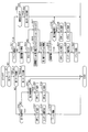
- FIG. 1 is an overall configuration diagram of the power supply system of the first embodiment.
- FIG. 2 is a flowchart showing the procedure of the control process of the first embodiment.
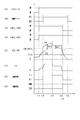
- FIG. 3 is a time chart showing an example of the control process of the first embodiment.
- FIG. 4 is a flowchart showing the procedure of the control process of the second embodiment.
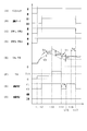
- FIG. 5 is a time chart showing an example of the control process of the second embodiment.
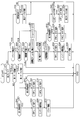
- FIG. 6 is an overall configuration diagram of a power supply system of another embodiment.
- the power supply system 100 is a system that supplies electric power to a general load 30 and a specific load 32.
- the power supply system 100 includes a high-voltage storage battery 10, a DCDC converter (hereinafter, simply a converter) 12, a first low-voltage storage battery 14, a second low-voltage storage battery 16 as a power storage device, a first switch unit 20, and a second switch unit. 24 and a control device 40 are provided.
- the high-voltage storage battery 10 has a higher rated voltage (for example, several hundred V) than the first low-voltage storage battery 14 and the second low-voltage storage battery 16, and is, for example, a lithium-ion storage battery.
- the converter 12 converts the electric power supplied from the high-voltage storage battery 10 into the electric power of the first voltage VA as the driving voltage (for example, 12V) of the general load 30 and the specific load 32, and supplies the electric power to the general load 30 and the specific load 32. do.
- the general load 30 is an electric load (hereinafter, simply a load) that is not used to support the driving of a vehicle, and is, for example, an air conditioner, an audio device, a power window, or the like.
- the specific load 32 is a load that implements at least one function used for driving support of the vehicle.
- the specific load 32 is a load that implements the driving support function of the vehicle, for example, an electric power steering device 50 that controls the steering of the vehicle, an electric brake device 51 that applies braking force to the wheels, and a situation around the vehicle. It is a traveling control device 52 and the like for monitoring.
- the specific load 32 has a first load 34 and a second load 36 redundantly provided for each function so that the function is not lost even if an abnormality occurs.
- the electric power steering device 50 has a first steering motor 50A and a second steering motor 50B.
- the electric brake device 51 has a first brake device 51A and a second brake device 51B.
- the travel control device 52 has a camera 52A and a laser radar 52B.
- the first steering motor 50A, the first brake device 51A, and the camera 52A correspond to the first load 34
- the second steering motor 50B, the second brake device 51B, and the laser radar 52B correspond to the second load 36. ..
- the first load 34 and the second load 36 together realize one function, but each of them can realize a part of the function by itself.
- the first steering motor 50A and the second steering motor 50B allow the vehicle to be freely steered, and each steering motor 50A is subject to certain restrictions such as steering speed and steering range. , 50B enables steering of the vehicle.
- Each specific load 32 realizes a function of supporting control by the driver in manual operation. Further, each specific load 32 realizes a function required for automatic driving in automatic driving that automatically controls behavior such as running and stopping of the vehicle. Therefore, the specific load 32 can also be said to be a load that performs at least one function necessary for driving the vehicle.
- the first load 34 is connected to the converter 12 via the path LA1 in the first system, and the first low voltage storage battery 14 and the general load 30 are connected to the path LA1 in the first system.
- the first low voltage storage battery 14 is, for example, a lead storage battery.
- the first system ES1 is configured by the converter 12, the first low-voltage storage battery 14, the general load 30, and the first load 34 connected by the path LA1 in the first system.
- the converter 12 and the first low-voltage storage battery 14 correspond to the "first power source", and the converter 12 corresponds to the "voltage generation unit".
- the second load 36 is connected to the second low voltage storage battery 16 via the path LA2 in the second system.
- the second low voltage storage battery 16 is, for example, a lithium ion storage battery.
- the second system ES2 is configured by the second low-voltage storage battery 16 and the second load 36 connected by the path LA2 in the second system.
- the second low voltage storage battery 16 corresponds to the "second power source”.
- the first switch unit 20 is provided in the connection path LB that connects each system to each other.
- the connection path LB connects the path LA1 in the first system and the path LA2 in the second system, and the first switch unit 20 includes a first switch SW1 and a second switch SW2 connected in series. ..
- the first switch SW1 is provided on the first system ES1 side of the second switch SW2.
- the first switch SW1 and the second switch SW2 correspond to "intersystem switches".
- N-channel MOSFETs (hereinafter, simply MOSFETs) are used as the first and second switches SW1 and SW2. Therefore, the first parasitic diode DA1 is connected in parallel to the first switch SW1, and the second parasitic diode DA2 is connected in parallel to the second switch SW2.
- the first and second switches SW1 and SW2 are connected in series so that the directions of the first and second parasitic diodes DA1 and DA2 are opposite to each other.
- the first parasitic diode DA1 is arranged so that the anode is on the second system ES2 side and the cathode is on the first system ES1 side
- the second parasitic diode DA2 has the anode on the first system ES1 side.
- the cathode is arranged so as to be on the second system ES2 side.
- the connection path LB is provided with a current detection unit 28.
- the current detection unit 28 is provided in the portion of the connection path LB on the side of the first system ES1 with respect to the first switch unit 20, and detects the magnitude and direction of the inter-system current IA flowing in the portion. Specifically, the current detection unit 28 detects the magnitude of the inter-system current IA flowing from the first system ES1 to the second system ES2 in the connection path LB as a positive direction. The detected value of the current detection unit 28 is input to the control device 40.
- the second switch unit 24 is provided in the path LA2 in the second system. Specifically, the second switch unit 24 is provided between the connection point with the connection path LB and the second low-voltage storage battery 16 in the second system internal path LA2, and is provided with the third switch SW3 connected in series. It is equipped with a fourth switch SW4. In the second switch unit 24, the third switch SW3 is provided on the connection path LB side of the fourth switch SW4.
- MOSFETs are used as the third and fourth switches SW3 and SW4. Therefore, the third parasitic diode DA3 is connected in parallel to the third switch SW3, and the fourth parasitic diode DA4 is connected in parallel to the fourth switch SW4.
- the third and fourth switches SW3 and SW4 are connected in series so that the directions of the third and fourth parasitic diodes DA3 and DA4 are opposite to each other.
- the third parasitic diode DA3 is arranged so that the anode is on the second low voltage storage battery 16 side and the cathode is on the connection path LB side
- the fourth parasitic diode DA4 has the anode on the connection path LB side and the cathode. Is arranged so as to be on the side of the second low-voltage storage battery 16.
- the control device 40 acquires the detected value of the current detection unit 28 and the in-system current flowing through the first and second in-system paths LA1 and LA2. Then, based on these, in order to switch the first to fourth switches SW1 to SW4, the first to fourth switching signals SC1 to SC4 are generated, and the command by the first to fourth switching signals SC1 to SC4 is given. Outputs to the 1st to 4th switches SW1 to SW4. Further, the control device 40 generates a control signal SD in order to control the operation of the converter 12, and outputs a command by the control signal SD to the converter 12.
- the control signal SD variably controls the first voltage VA generated by the converter 12, and switches between the operating state and the stopped state of the converter 12.
- control device 40 is connected to the notification unit 44, the IG switch 45, and the input unit 46, and controls these.
- the notification unit 44 is a device that visually or audibly notifies the driver, and is, for example, a display or a speaker installed in a vehicle interior.
- the IG switch 45 is a vehicle start switch.
- the control device 40 monitors the open / closed state of the IG switch 45.
- the input unit 46 is a device that accepts the operation of the driver, for example, a handle, a lever, a button, a pedal, and a voice input device.
- the control device 40 manually drives and automatically drives the vehicle using the above-mentioned specific load 32.
- the control device 40 includes a well-known microcomputer including a CPU, a memory such as a ROM or RAM, and a flash memory.
- the CPU realizes various functions for manual operation and automatic operation by referring to an arithmetic program and control data in the memory.
- manual driving represents a state in which the vehicle is controlled by the operation of the driver.
- automatic driving represents a state in which the vehicle is driven and controlled by the control content by the control device 40 regardless of the operation of the driver.
- automatic driving refers to automatic driving of level 3 or higher among the automatic driving levels from level 0 to level 5 defined by the National Highway Traffic Safety Administration (NHTSA).
- Level 3 is a level at which the control device 40 controls both steering wheel operation and acceleration / deceleration while observing the traveling environment.
- control device 40 can implement a driving support function such as LKA (Lane Keeping Assist), LCA (Lane Change Assist), PCS (Pre-Crash Safety) by using the specific load 32 described above.
- the control device 40 can switch the driving mode of the vehicle between a first mode in which the driving support function is used and a second mode in which the driving support function is not used, and the vehicle can travel in each driving mode. ..
- the control device 40 switches between the first mode and the second mode according to the driver switching instruction via the input unit 46.
- the first mode includes a mode in which the driver manually drives the vehicle using the driving support function, and a mode in which the vehicle is automatically driven.
- the second mode is a mode in which the driver manually drives the vehicle without using the driving support function.
- the control device 40 determines whether or not an abnormality has occurred in the first system ES1 and the second system ES2, and if it is determined that no abnormality has occurred in any of the systems ES1 and ES2,
- the first load 34 and the second load 36 are used to automatically drive the vehicle and support driving.
- the first and second loads 34 and 36 cooperate to carry out one function necessary for automatic driving and driving support.
- the abnormality is a power failure abnormality such as a ground fault or a disconnection.
- the first and second switches SW1 and SW2 are opened, and the first system ES1 and the second system ES2 are electrically isolated. do.
- the loads 34 and 36 of the other system ES1 and ES2 in which the abnormality has not occurred can be driven.
- the first voltage VA generated by the converter 12 is set to a target voltage Vtg higher than the second voltage VB, which is the voltage between the terminals of the second low-voltage storage battery 16, so that the converter 12 to the first load 34 and A control process for supplying power to the second load 36 is performed.
- Vtg the target voltage
- VB the voltage between the terminals of the second low-voltage storage battery 16
- FIG. 2 shows a flowchart of the control process of the present embodiment.
- the control device 40 When the IG switch 45 is switched to the closed state, the control device 40 repeatedly executes the control process at predetermined control cycles. At the beginning of switching the IG switch 45 to the closed state, the driving mode of the vehicle is set to the second mode, and the first to fourth switches SW1 to SW4 are set to the closed state.
- step S10 it is determined whether or not the driving mode of the vehicle is the second mode. If an affirmative determination is made in step S10, it is determined in step S12 whether or not the vehicle is to be driven in the first mode. For example, when an abnormality occurs in either the first system ES1 or the second system ES2, since the precondition for executing the first mode is not satisfied, a negative determination is made in step S12, and steps S60 and S62 are performed. Proceed to.
- step S14 the driving mode of the vehicle is switched from the second mode to the first mode, and the control process is terminated.
- the switching to the first mode is performed when, for example, an instruction to use the driving support function or an instruction to automatically drive is input from the driver via the input unit 46.
- step S10 it is determined in step S20 whether the driver is being notified.
- the driver notification notifies the driver that an abnormality has occurred in either the first system ES1 or the second system ES2, informs the driver that the first mode is to be canceled, and switches to the second mode. Is to encourage.
- the remaining capacity SA of the second low-voltage storage battery 16 is calculated in step S22.
- the remaining capacity SA is, for example, an SOC (State Of Charge) indicating the state of charge of the second low-voltage storage battery 16.
- SOC State Of Charge
- the remaining capacity SA is calculated by using the current integrated value which is the time integrated value of the charge / discharge current of the second low voltage storage battery 16 when the second low voltage storage battery 16 is in the energized state (charged state or discharged state). ..
- step S24 it is determined whether or not the remaining capacity SA calculated in step S22 is larger than the predetermined capacity threshold value Sth.
- the second low-voltage storage battery 16 is a storage battery that can be charged by supplying electric power from the converter 12, and the capacity threshold Sth is the upper limit charge capacity of the second low-voltage storage battery 16. Therefore, when the remaining capacity SA is smaller than the capacity threshold value Sth, the second low-voltage storage battery 16 is charged by the power supply from the converter 12.
- step S24 When the remaining capacity SA is larger than the capacity threshold value Sth and the second low-voltage storage battery 16 is not charged, a positive determination is made in step S24. In this case, in step S26, the target voltage Vtg is set so that the voltage difference between the target voltage Vtg and the second voltage VB becomes the first voltage difference ⁇ V1, and the process proceeds to step S28.
- step S24 when the remaining capacity SA is smaller than the capacity threshold value Sth and the second low-voltage storage battery 16 is charged, a negative determination is made in step S24.
- the target voltage Vtg is set so that the voltage difference between the target voltage Vtg and the second voltage VB becomes the second voltage difference ⁇ V2, and the process proceeds to step S28.
- the second voltage difference ⁇ V2 is set to a voltage difference larger than that of the first voltage difference ⁇ V1. That is, in the control process of the present embodiment, the target voltage Vtg is set higher when the second low voltage storage battery 16 is charged than when the second low voltage storage battery 16 is not charged.
- the first and second voltage differences ⁇ V1 and ⁇ V2 are the characteristics of the second low-voltage storage battery 16 such as the remaining capacity SA and the temperature of the second low-voltage storage battery 16, and the first and second in-system routes LA1 and LA2 and the connection path LB. It is set based on the wiring resistance.
- step S28 the first voltage VA is controlled to the target voltage Vtg.
- the first voltage VA becomes higher than the second voltage VB, and the converter 12 is in the first state in which power is supplied to the first load 34 and the second load 36.
- the process of step S28 corresponds to the "first control unit".
- step S30 it is determined that an abnormality has occurred in either the first system ES1 or the second system ES2.
- step S30 it is determined whether or not an abnormality has occurred in the first system ES1. Specifically, in the first state, it is determined whether or not a reverse current from the second system ES2 to the first system ES1 has flowed in the connection path LB, and more specifically, the system acquired from the current detection unit 28. It is determined whether or not the intercurrent current IA is negative.
- step S30 If it is determined that the inter-system current IA acquired from the current detection unit 28 is positive and no reverse current is flowing in the connection path LB, a negative determination is made in step S30. In this case, in step S32, it is determined whether or not an abnormality has occurred in the second system ES2. Specifically, it is determined whether or not a short-circuit current has flowed in the path LA2 in the second system.
- step S32 If it is determined that no abnormality has occurred in any of the systems ES1 and ES2, a negative determination is made in step S32. In this case, the control process is terminated and the vehicle continues to run in the first mode.
- step S34 an open command is output to the first and second switches SW1 and SW2.
- step S36 a command for switching the converter 12 to the stopped operation state is output.
- the power supply from the high-pressure storage battery 10 to the first load 34 and the second load 36 and the power supply from the second low-pressure storage battery 16 to the first load 34 are stopped, and the second low-pressure storage battery 16 to the second load 36 are stopped. It becomes the second state in which power is supplied to.
- the process of step S34 corresponds to the "second control unit".
- step S32 an open command is output to the first and second switches SW1 and SW2 in step S38.
- step S40 an open command is output to the third and fourth switches SW3 and SW4.
- the first and second switches SW1 and SW2 are first opened, and the loads 34 and 36 on the system side where no abnormality has occurred are applied. Secure power supply. After that, the power supply from the high-voltage storage battery 10 and the second low-voltage storage battery 16 is stopped, and the over-discharging of these storage batteries 10 and 16 is suppressed.
- step S42 the driver is notified via the notification unit 44 that the first mode is to be stopped, and the control process is terminated.
- step S50 it is determined in step S50 whether or not a switching instruction to the second mode has been input from the driver via the input unit 46. That is, it is determined whether or not there is a response from the driver in response to the notification. If a negative determination is made in step S50, the control process is terminated, and the running of the vehicle in the first mode is continued using the loads 34 and 36 on the system side where no abnormality has occurred.
- step S50 the driving mode of the vehicle is switched from the first mode to the second mode in step S52, and the control process is terminated.
- step S60 it is determined that an abnormality has occurred in either the first system ES1 or the second system ES2.
- step S60 it is determined whether or not an abnormality has occurred in the first system ES1. If a negative determination is made in step S60, it is determined in step S62 whether or not an abnormality has occurred in the second system ES2.
- the first and second switches SW1 and SW2 may be in the open state, so that the occurrence of an abnormality is determined by whether or not a short-circuit current has flowed through the paths LA1 and LA2 in each system. Will be done.
- step S62 If it is determined that no abnormality has occurred in any of the systems ES1 and ES2, a negative determination is made in step S62. In this case, the control process is terminated and the vehicle continues to run in the second mode.
- step S60 if an affirmative determination is made in step S60, an open command is output to the first and second switches SW1 and SW2 in step S64. In the following step S66, a command for switching the converter 12 to the stopped operation state is output.
- step S62 an open command is output to the first and second switches SW1 and SW2 in step S68.
- step S70 an open command is output to the third and fourth switches SW3 and SW4.
- step S72 the driver is notified via the notification unit 44 that an abnormality has occurred in either the first system ES1 or the second system ES2, and the control process is terminated.
- FIG. 3 shows an example of control processing.
- FIG. 3 shows the transition of the first voltage VA and the second voltage VB when a ground fault occurs in the first system ES1 while the vehicle is running in the first mode.
- FIG. 3 shows the transition of the state of the IG switch 45, and (B) shows the transition of the driving mode of the vehicle. Further, (C) shows the transition of the open / closed state of the first and second switches SW1 and SW2, and (D) shows the transition of the open / closed state of the third and fourth switches SW3 and SW4. Further, (E) shows the transition of the first voltage VA and the second voltage VB, (F) shows the transition of the inter-system current IA, (G) shows the transition value of the cutoff determination, and (H). ) Indicates the transition of the judgment result of the ground fault.
- the cutoff determination means a determination that a current has flowed from the second system ES2 to the first system ES1 in the connection path LB, and is turned on when this determination is made, and when this determination is not made. It turns off. Further, in FIG. 3E, the transition of the first voltage VA is shown by a solid line, and the transition of the second voltage VB is shown by a broken line.
- the first to fourth switches SW1 to SW4 are in the closed state, and the converter 12 is in the operation stopped state. It has been switched to. Therefore, during the closed period of the IG switch 45, the inter-system current IA becomes zero.
- the third and fourth switches SW3 and SW4 are closed, and the converter 12 is switched to the operating state.
- the first and second voltages VA and VB increase.
- the first voltage VA is controlled to be equal to the second voltage VB. Therefore, the magnitude of the inter-system current IA is relatively small, and the direction of the inter-system current IA repeatedly fluctuates.
- the driving mode of the vehicle is switched from the second mode to the first mode at time t2.
- the first voltage VA is controlled to have a target voltage Vtg higher than the second voltage VB.
- the inter-system current IA flows from the first system ES1 to the second system ES2 due to the voltage difference between the target voltage Vtg and the second voltage VB.
- the cutoff determination is turned on at time t2, and the determination that the current has flowed from the second system ES2 to the first system ES1 in the connection path LB is started.
- the remaining capacity SA of the second low-voltage storage battery 16 has not reached the capacity threshold Sth, and the second voltage VB has not risen to the drive voltage VM. Therefore, the second low-voltage storage battery 16 is charged by the converter 12.
- the target voltage Vtg is set to a voltage higher than the second voltage VB by the second voltage difference ⁇ V2.
- the target voltage Vtg is changed to a voltage higher than the second voltage VB by the first voltage difference ⁇ V1. That is, after the charging of the second low voltage storage battery 16 is completed, the target voltage Vtg is set lower than that during the charging of the second low voltage storage battery 16.
- the first and second switches SW1 and SW2 are switched to the closed state.
- a ground fault occurs in the first system ES1 at time t4.
- the first voltage VA and the second voltage VB are lowered.
- the inter-system current IA is reduced.
- the inter-system current IA decreases from zero at the subsequent time t5 due to the decrease in the inter-system current IA. Then, it is determined by the cutoff determination that the reverse current from the second system ES2 to the first system ES1 has flowed in the connection path LB.
- the load current is suppressed from flowing from the second system ES2 to the first system ES1 via the connection path LB. Therefore, when it is determined by the cutoff determination that a reverse current has flowed in the connection path LB, it can be determined that a ground fault has occurred in the first system ES1.
- the driving mode of the vehicle is switched from the first mode to the second mode at time t6.
- the first and second switches SW1 and SW2 are provided in the first connection path LB1 that connects the first and second systems ES1 and ES2 to each other. Therefore, by closing the first and second switches SW1 and SW2, mutual power can be supplied between the first and second systems ES1 and ES2, and the first load 34 and the second load 36 can be supplied with each other. Therefore, redundant power supply is possible by the converter 12 and the first and second low voltage storage batteries 14 and 16. If it is determined that an abnormality has occurred in one of the systems ES1 and ES2, the first and second switches SW1 and SW2 are closed to close the other system ES1 and ES2 in which no abnormality has occurred. It is possible to continue driving the loads 34 and 36 in.
- the first voltage VA is made higher than the second voltage VB, so that the converter 12 to the first load 34 and the second load I made 36 supply power.
- the inter-system current IA is suppressed from flowing from the second system ES2 to the first system ES1 via the connection path LB. Therefore, when a reverse current flows from the second system ES2 to the first system ES1 in the connection path LB, it can be determined that the current generation is caused by an abnormality. Then, by opening the first and second switches SW1 and SW2, it is possible to supply electric power from the second low voltage storage battery 16 to the second load 36.
- the driving of the second load 36 can be continued. As a result, it is possible to continue driving the loads 34 and 36 even when an abnormality occurs while suppressing erroneous detection of the abnormality.
- the first load 34 and the second load 36 are functions necessary for operation and are loads for implementing the operation support function, and the operation is performed using these loads 34 and 36. It is possible to switch between driving in the first mode using the support function and driving in the second mode without using the driving support function. Then, in the first mode, the first voltage VA is set to a target voltage Vtg higher than the second voltage VB, so that the converter 12 supplies power to the first load 34 and the second load 36. Further, when it is determined that the reverse current from the second system ES2 to the first system ES1 has flowed in the connection path LB in this first mode, the first and second switches SW1 and SW2 are opened.
- the second low-voltage storage battery 16 is made to supply electric power to the second load 36.
- the driving support function it is possible to continue driving the loads 34 and 36 even if an abnormality occurs while suppressing erroneous detection of the abnormality, and the driving support function can be continuously used. Can be done.
- the converter 12 can variably control the first voltage VA, and controls the first voltage V1 based on the target voltage Vtg having a predetermined voltage difference ⁇ V1 and ⁇ V2 with respect to the second voltage VB. .. Therefore, when the first voltage VA is set to the target voltage Vtg, the voltage differences ⁇ V1 and ⁇ V2 are secured between the first voltage VA and the second voltage VB. Therefore, even if the inter-system current IA flowing from the first system ES1 to the second system ES2 via the connection path LB fluctuates when the first load 34 and the second load 36 are driven, the voltage differences ⁇ V1 and ⁇ V2 cause the current IA. The reverse current flowing through the connection path LB is suppressed. This makes it possible to suppress erroneous detection of abnormalities.
- the first system ES1 includes a converter 12 that buck-generates the power of the first voltage VA from the power supplied from the high-voltage storage battery 10. Therefore, the converter 12 can generate a first voltage VA as a drive voltage for the first load 34 and the second load 36, and supply the first voltage VA to each of the loads 34 and 36. Further, since the second low-voltage storage battery 16 is included in the second system ES2, the power supply to the respective loads 34 and 36 can be continued even if the power supply fails in the first system ES1.
- the second low-voltage storage battery 16 is appropriately supplied with charging power from the converter 12 in response to a decrease in the second voltage VB.
- the connection path LB is provided by the remaining capacity SA of the second low-voltage storage battery 16.
- the charging current that flows through the battery fluctuates.
- the target voltage Vtg is set higher than when the second low voltage storage battery 16 is not charged. As a result, the reverse current flow is suppressed, and erroneous detection of abnormalities can be suitably suppressed.
- the present embodiment is different from the first embodiment in that in the first mode, the drive amount information indicating the drive amount TR of the first load 34 and the second load 36 is acquired.
- the drive amount TR is the output torque
- the drive amount information is information indicating the command value of the output torque.
- the operation mode is switched from the first mode to the second mode based on the comparison result. Is different.
- FIG. 4 shows a flowchart of the control process of the present embodiment.
- the same processing as that shown in FIG. 2 above is given the same step number for convenience, and the description thereof will be omitted.
- the drive amount information in the first load 34 and the second load 36 is acquired in step S80, and the drive amount TR indicated by the acquired drive amount information is a predetermined drive. It is determined whether or not it is larger than the quantity threshold value Tth.
- the drive amount threshold Tth is a drive amount in which the inter-system current IA may fluctuate more than the second voltage difference ⁇ V2.
- step S80 If the drive amount TR is smaller than the drive amount threshold value Tth, a negative determination is made in step S80. In this case, in step S82, it is determined whether or not the drive amount TR has decreased beyond the drive amount threshold value Tth. Specifically, it is determined whether or not the drive amount TR has switched from a state larger than the drive amount threshold Tth to a state smaller than the drive amount threshold Tth.
- the drive amount information acquired in each control process is stored in the memory in the control device 40, and in step S82, whether or not the drive amount TR acquired in the previous control process is larger than the drive amount threshold Tth. Is determined.
- step S82 When the drive amount TR acquired in the previous control process is larger than the drive amount threshold Tth and the drive amount TR is switched from a state larger than the drive amount threshold Tth to a state smaller than the drive amount threshold Tth, step S82. Judge affirmatively with. In this case, in step S30, the control process is terminated without determining whether or not a current has flowed from the second system ES2 to the first system ES1 in the connection path LB. In this case, even if a reverse current flows through the connection path LB, the first and second switches SW1 and SW2 in step S34 are not switched to the open state, and this switching process is stopped.
- step S82 the target voltage Vtg is set so that the voltage difference between the target voltage Vtg and the second voltage VB becomes the first voltage difference ⁇ V1.
- step S80 when the drive amount TR is larger than the drive amount threshold value Tth, an affirmative determination is made in step S80.
- step S85 the target voltage Vtg is set so that the voltage difference between the target voltage Vtg and the second voltage VB is the second voltage difference ⁇ V2.
- the second voltage difference ⁇ V2 is set to a voltage difference larger than that of the first voltage difference ⁇ V1. Therefore, in the control process of the present embodiment, when the drive amount TR is larger than the drive amount threshold Tth, the target voltage Vtg is set higher than when the drive amount TR is smaller than the drive amount threshold Tth.
- step S90 it is determined in step S90 whether or not the first voltage VA is lower than the target voltage Vtg. Specifically, it is determined whether or not the first voltage VA is maintained at a state lower than the target voltage Vtg for a predetermined period TS.
- the process of step S90 corresponds to the "voltage determination unit".
- step S92 an open command is output to the first and second switches SW1 and SW2.
- step S94 the driving mode of the vehicle is switched from the first mode to the second mode, and the control process is terminated.
- the process of step S94 corresponds to the "mode control unit".
- step S90 determines whether the first voltage VA is lower than the target voltage Vtg is lower than the target voltage Vtg. If the state where the first voltage VA is lower than the target voltage Vtg does not continue for a predetermined period TS, it is determined that the first voltage VA is not lower than the target voltage Vtg, and a negative determination is made in step S90. do. In this case, the control process is terminated without switching the driving mode of the vehicle from the first mode to the second mode.
- FIG. 5 shows an example of control processing.
- FIG. 5 shows the transition of the first voltage VA and the second voltage VB when the first voltage VA drops below the target voltage Vtg while the vehicle is running in the first mode.
- FIG. 5 shows the transition of the drive amount TR. Note that (A) to (E), (G), and (H) in FIG. 5 are the same as (A) to (E), (G), and (H) in FIG. Further, the processing from time t1 to time t2 in FIG. 5 is the same as the processing from time t1 to time t2 in FIG. Therefore, duplicate explanations will be omitted.
- the driving mode of the vehicle is switched from the second mode to the first mode at time t2.
- the target voltage Vtg is set to a voltage higher than the second voltage VB by the first voltage difference ⁇ V1.
- the second voltage VB decreases. Further, as the drive amount TR increases, the target voltage Vtg is changed to a voltage higher than the second voltage VB by the second voltage difference ⁇ V2. That is, when the drive amount TR is larger than the drive amount threshold Tth, the target voltage Vtg is set higher than when the drive amount TR is smaller than the drive amount threshold Tth.
- the target voltage Vtg is changed to a voltage higher than the second voltage VB by the first voltage difference ⁇ V1. Further, as the drive amount TR decreases, the decrease of the second voltage VB stops. As shown in FIG. 5 (E), after the drive amount TR is lowered, the second voltage VB becomes unstable, and as shown by the arrow Y1, a sudden change in the second voltage VB occurs. Then, when the maximum value of the suddenly changed second voltage VB exceeds the target voltage Vtg, it is determined that a reverse current has flowed in the connection path LB, and the first and second switches SW1 and SW2 are erroneously switched to the open state. ..
- the first period TA elapses after the state becomes smaller than the drive amount threshold Tth.
- the cutoff judgment is turned off in the meantime. Specifically, the cutoff determination is turned off in the first period TA from the time t14 to the time t15. As a result, it is possible to prevent the first and second switches SW1 and SW2 from being erroneously switched to the open state due to the sudden change in the second voltage VB generated in the first period TA.
- the operation mode of the vehicle is switched from the first mode to the second mode.
- the first voltage VA starts to decrease from the target voltage Vtg at time t16.
- the first voltage VA is maintained lower than the target voltage Vtg for a predetermined period TS from the time t16 to the time t17, the first voltage VA is lower than the target voltage Vtg at the time t17. Is determined.
- the driving mode of the vehicle is switched from the first mode to the second mode at time t17.
- the driving mode of the vehicle is switched from the first mode to the second mode at time t17.
- the amount of change in the current flowing through the connection path LB is proportional to the drive amount TR of the first load 34 and the second load 36. Therefore, when the drive amount TR is large, the amount of change in the current flowing through the connection path LB becomes large. As a result, when a reverse current flows through the connection path LB, an abnormality is erroneously detected.
- the drive amount TR is larger than the drive amount threshold Tth
- the first voltage VA is set higher than when the drive amount TR is smaller than the drive amount threshold Tth. As a result, the reverse current flow is suppressed, and erroneous detection of an abnormality can be suitably suppressed.
- the drive amount TR decreases, the second voltage VB becomes unstable, and the current flowing through the connection path LB tends to increase.
- the first and second switches SW1 and SW2 are erroneously opened due to an erroneous detection of an abnormality.
- the drive amount TR is switched from a state larger than the drive amount threshold value Tth to a state smaller than the drive amount threshold value Tth, the switching process of the first and second switches SW1 and SW2 to the open state is stopped. bottom. As a result, it is possible to prevent the first and second switches SW1 and SW2 from being erroneously opened due to an erroneous detection of an abnormality.
- the first voltage VA may not be able to be raised to the target voltage Vtg due to a decrease in the SOC of the high-voltage storage battery 10.
- the voltage difference between the first voltage VA and the second voltage VB becomes small, and an abnormality is erroneously detected depending on the magnitude of the fluctuation of the drive amount TR.
- the operation support function provides redundant power supply to the loads 34 and 36. I can't do it.
- the traveling mode of the vehicle when it is determined that the first voltage VA is lower than the target voltage Vtg, the traveling mode of the vehicle is switched from the first mode to the second mode.
- the operation support function it is possible to prevent the operation support function from being continuously used in a state where redundant power supply to each of the loads 34 and 36 cannot be performed.
- Each load 34, 36 may be, for example, the following device.
- each of the first and second loads 34 and 36 is, for example, a three-phase permanent magnet synchronous motor and a three-phase inverter device.
- each of the first and second loads 34 and 36 is, for example, an ABS actuator that can independently adjust the brake oil pressure during braking.
- each of the first and second loads 34 and 36 is, for example, a millimeter wave radar.
- the loads 34 and 36 do not necessarily have to be a combination having the same configuration, and may be a combination that realizes the same function with devices of different types.
- the first and second switches SW1 and SW2 are not limited to MOSFETs, and may be, for example, IGBTs. The same applies to the third and fourth switches SW3 and SW4.
- the voltage generation unit of the first system ES1 is not limited to the converter 12, but may be an alternator. Further, the first system ES1 may not have a voltage generation unit, and may have, for example, only the first low voltage storage battery 16.
- the target voltage Vtg is set higher than the second voltage VB based on the second voltage VB is shown, but the present invention is not limited to this.
- the first voltage VA and the second voltage VB may be acquired, and the target voltage Vtg may be set higher than the second voltage VB based on these voltage differences.
- the magnitude and direction of the inter-system current IA may be acquired, and the target voltage Vtg may be set higher than the second voltage VB based on these.
- the present invention is not limited to this.
- one first system and two second systems may be provided.
- the two second systems are referred to as the second system ES2 and the third system ES3.
- the first voltage VA in the first system ES1 is a voltage higher than the third voltage VC which is the voltage between the terminals of the second voltage VB in the second system ES2 and the third low voltage storage battery 18 in the third system ES3.
- the target voltage Vtg is set higher when the second low voltage storage battery 16 is charged than when the second low voltage storage battery 16 is not charged.
- the target voltage Vtg may be set.
- the target voltage Vtg is set higher when the drive amount TR is larger than the drive amount threshold Tth than when the drive amount TR is smaller than the drive amount threshold Tth, but the present invention is not limited to this.
- the larger the drive amount TR the higher the target voltage Vtg may be set.
- the first mode may be set regardless of the driving mode of the vehicle.
- the power supply system 100 is applied to a vehicle capable of traveling by manual driving and automatic driving, but the present invention is not limited to this. It may be applied to a vehicle that can only be driven by automatic driving, such as a fully autonomous vehicle, or may be applied to a vehicle that can only be driven by manual driving.
- the loads 34 and 36 of the other system ES1 and ES2 in which the abnormality has not occurred are applied. It may be used to stop the running of the vehicle by automatic driving, or to stop the vehicle after moving it to a safe place.
Landscapes
- Engineering & Computer Science (AREA)
- Power Engineering (AREA)
- Mechanical Engineering (AREA)
- Charge And Discharge Circuits For Batteries Or The Like (AREA)
- Protection Of Static Devices (AREA)
Priority Applications (2)
| Application Number | Priority Date | Filing Date | Title |
|---|---|---|---|
| US17/986,320 US20230075428A1 (en) | 2020-05-13 | 2022-11-14 | Control apparatus and power supply system |
| US19/090,704 US20250222886A1 (en) | 2020-05-13 | 2025-03-26 | Control apparatus and power supply system |
Applications Claiming Priority (2)
| Application Number | Priority Date | Filing Date | Title |
|---|---|---|---|
| JP2020084632A JP7310701B2 (ja) | 2020-05-13 | 2020-05-13 | 制御装置及び電源システム |
| JP2020-084632 | 2020-05-13 |
Related Child Applications (1)
| Application Number | Title | Priority Date | Filing Date |
|---|---|---|---|
| US17/986,320 Continuation US20230075428A1 (en) | 2020-05-13 | 2022-11-14 | Control apparatus and power supply system |
Publications (1)
| Publication Number | Publication Date |
|---|---|
| WO2021230130A1 true WO2021230130A1 (ja) | 2021-11-18 |
Family
ID=78510631
Family Applications (1)
| Application Number | Title | Priority Date | Filing Date |
|---|---|---|---|
| PCT/JP2021/017359 Ceased WO2021230130A1 (ja) | 2020-05-13 | 2021-05-06 | 制御装置及び電源システム |
Country Status (3)
| Country | Link |
|---|---|
| US (2) | US20230075428A1 (enExample) |
| JP (1) | JP7310701B2 (enExample) |
| WO (1) | WO2021230130A1 (enExample) |
Cited By (1)
| Publication number | Priority date | Publication date | Assignee | Title |
|---|---|---|---|---|
| WO2024171422A1 (ja) * | 2023-02-17 | 2024-08-22 | 株式会社オートネットワーク技術研究所 | 異常判定装置 |
Families Citing this family (3)
| Publication number | Priority date | Publication date | Assignee | Title |
|---|---|---|---|---|
| JP7276291B2 (ja) * | 2020-05-22 | 2023-05-18 | 株式会社デンソー | 電源システム |
| JP7767114B2 (ja) | 2021-11-04 | 2025-11-11 | キヤノン株式会社 | 情報処理装置、情報処理システム、情報処理方法、およびプログラム |
| JP2025127013A (ja) * | 2024-02-20 | 2025-09-01 | 株式会社オートネットワーク技術研究所 | 車載用制御装置 |
Citations (3)
| Publication number | Priority date | Publication date | Assignee | Title |
|---|---|---|---|---|
| JP2016128283A (ja) * | 2015-01-09 | 2016-07-14 | 株式会社オートネットワーク技術研究所 | 自動車用電源供給装置及び電源ボックス |
| JP2018182864A (ja) * | 2017-04-10 | 2018-11-15 | 株式会社デンソー | 電力制御装置および電力制御方法 |
| JP2019062727A (ja) * | 2017-09-22 | 2019-04-18 | 株式会社デンソー | 電源システム |
-
2020
- 2020-05-13 JP JP2020084632A patent/JP7310701B2/ja active Active
-
2021
- 2021-05-06 WO PCT/JP2021/017359 patent/WO2021230130A1/ja not_active Ceased
-
2022
- 2022-11-14 US US17/986,320 patent/US20230075428A1/en not_active Abandoned
-
2025
- 2025-03-26 US US19/090,704 patent/US20250222886A1/en active Pending
Patent Citations (3)
| Publication number | Priority date | Publication date | Assignee | Title |
|---|---|---|---|---|
| JP2016128283A (ja) * | 2015-01-09 | 2016-07-14 | 株式会社オートネットワーク技術研究所 | 自動車用電源供給装置及び電源ボックス |
| JP2018182864A (ja) * | 2017-04-10 | 2018-11-15 | 株式会社デンソー | 電力制御装置および電力制御方法 |
| JP2019062727A (ja) * | 2017-09-22 | 2019-04-18 | 株式会社デンソー | 電源システム |
Cited By (1)
| Publication number | Priority date | Publication date | Assignee | Title |
|---|---|---|---|---|
| WO2024171422A1 (ja) * | 2023-02-17 | 2024-08-22 | 株式会社オートネットワーク技術研究所 | 異常判定装置 |
Also Published As
| Publication number | Publication date |
|---|---|
| JP2021180560A (ja) | 2021-11-18 |
| US20230075428A1 (en) | 2023-03-09 |
| JP7310701B2 (ja) | 2023-07-19 |
| US20250222886A1 (en) | 2025-07-10 |
Similar Documents
| Publication | Publication Date | Title |
|---|---|---|
| WO2021230130A1 (ja) | 制御装置及び電源システム | |
| CN115606069B (zh) | 电源系统 | |
| JP7363754B2 (ja) | 電源システム | |
| CN113511155B (zh) | 电源系统 | |
| JP7176497B2 (ja) | 電源システム | |
| US12202419B2 (en) | Power supply system | |
| CN113511148B (zh) | 电源系统 | |
| WO2023085130A1 (ja) | 電源監視装置及び制御システム | |
| WO2021235239A1 (ja) | 電源システム | |
| JP7586056B2 (ja) | 電源監視装置 | |
| JP7276291B2 (ja) | 電源システム | |
| JP7564780B2 (ja) | 電源システム | |
| JP7342819B2 (ja) | 電源システム | |
| US12506353B2 (en) | Power supply system | |
| WO2022091737A1 (ja) | 電源システム |
Legal Events
| Date | Code | Title | Description |
|---|---|---|---|
| 121 | Ep: the epo has been informed by wipo that ep was designated in this application |
Ref document number: 21804315 Country of ref document: EP Kind code of ref document: A1 |
|
| NENP | Non-entry into the national phase |
Ref country code: DE |
|
| 122 | Ep: pct application non-entry in european phase |
Ref document number: 21804315 Country of ref document: EP Kind code of ref document: A1 |