WO2021230087A1 - Wrong-way driving detecting device, and wrong-way driving detecting method - Google Patents
Wrong-way driving detecting device, and wrong-way driving detecting method Download PDFInfo
- Publication number
- WO2021230087A1 WO2021230087A1 PCT/JP2021/016983 JP2021016983W WO2021230087A1 WO 2021230087 A1 WO2021230087 A1 WO 2021230087A1 JP 2021016983 W JP2021016983 W JP 2021016983W WO 2021230087 A1 WO2021230087 A1 WO 2021230087A1
- Authority
- WO
- WIPO (PCT)
- Prior art keywords
- road surface
- surface profile
- vehicle
- reverse
- information
- Prior art date
Links
- 238000000034 method Methods 0.000 title description 17
- 238000001514 detection method Methods 0.000 claims description 46
- 238000006243 chemical reaction Methods 0.000 claims description 4
- 230000001133 acceleration Effects 0.000 description 28
- 238000004891 communication Methods 0.000 description 15
- 230000007423 decrease Effects 0.000 description 5
- 238000010586 diagram Methods 0.000 description 5
- 230000000694 effects Effects 0.000 description 2
- 230000002093 peripheral effect Effects 0.000 description 2
- 238000012545 processing Methods 0.000 description 2
- 230000001771 impaired effect Effects 0.000 description 1
- 238000005259 measurement Methods 0.000 description 1
- 238000012986 modification Methods 0.000 description 1
- 230000004048 modification Effects 0.000 description 1
- 230000003746 surface roughness Effects 0.000 description 1
Images


Classifications
-
- B—PERFORMING OPERATIONS; TRANSPORTING
- B60—VEHICLES IN GENERAL
- B60W—CONJOINT CONTROL OF VEHICLE SUB-UNITS OF DIFFERENT TYPE OR DIFFERENT FUNCTION; CONTROL SYSTEMS SPECIALLY ADAPTED FOR HYBRID VEHICLES; ROAD VEHICLE DRIVE CONTROL SYSTEMS FOR PURPOSES NOT RELATED TO THE CONTROL OF A PARTICULAR SUB-UNIT
- B60W40/00—Estimation or calculation of non-directly measurable driving parameters for road vehicle drive control systems not related to the control of a particular sub unit, e.g. by using mathematical models
- B60W40/10—Estimation or calculation of non-directly measurable driving parameters for road vehicle drive control systems not related to the control of a particular sub unit, e.g. by using mathematical models related to vehicle motion
-
- B—PERFORMING OPERATIONS; TRANSPORTING
- B60—VEHICLES IN GENERAL
- B60W—CONJOINT CONTROL OF VEHICLE SUB-UNITS OF DIFFERENT TYPE OR DIFFERENT FUNCTION; CONTROL SYSTEMS SPECIALLY ADAPTED FOR HYBRID VEHICLES; ROAD VEHICLE DRIVE CONTROL SYSTEMS FOR PURPOSES NOT RELATED TO THE CONTROL OF A PARTICULAR SUB-UNIT
- B60W40/00—Estimation or calculation of non-directly measurable driving parameters for road vehicle drive control systems not related to the control of a particular sub unit, e.g. by using mathematical models
- B60W40/02—Estimation or calculation of non-directly measurable driving parameters for road vehicle drive control systems not related to the control of a particular sub unit, e.g. by using mathematical models related to ambient conditions
- B60W40/06—Road conditions
-
- B—PERFORMING OPERATIONS; TRANSPORTING
- B60—VEHICLES IN GENERAL
- B60W—CONJOINT CONTROL OF VEHICLE SUB-UNITS OF DIFFERENT TYPE OR DIFFERENT FUNCTION; CONTROL SYSTEMS SPECIALLY ADAPTED FOR HYBRID VEHICLES; ROAD VEHICLE DRIVE CONTROL SYSTEMS FOR PURPOSES NOT RELATED TO THE CONTROL OF A PARTICULAR SUB-UNIT
- B60W50/00—Details of control systems for road vehicle drive control not related to the control of a particular sub-unit, e.g. process diagnostic or vehicle driver interfaces
- B60W50/08—Interaction between the driver and the control system
- B60W50/14—Means for informing the driver, warning the driver or prompting a driver intervention
-
- G—PHYSICS
- G05—CONTROLLING; REGULATING
- G05D—SYSTEMS FOR CONTROLLING OR REGULATING NON-ELECTRIC VARIABLES
- G05D1/00—Control of position, course, altitude or attitude of land, water, air or space vehicles, e.g. using automatic pilots
- G05D1/20—Control system inputs
- G05D1/24—Arrangements for determining position or orientation
- G05D1/243—Means capturing signals occurring naturally from the environment, e.g. ambient optical, acoustic, gravitational or magnetic signals
- G05D1/2437—Extracting relative motion information
-
- G—PHYSICS
- G05—CONTROLLING; REGULATING
- G05D—SYSTEMS FOR CONTROLLING OR REGULATING NON-ELECTRIC VARIABLES
- G05D1/00—Control of position, course, altitude or attitude of land, water, air or space vehicles, e.g. using automatic pilots
- G05D1/20—Control system inputs
- G05D1/24—Arrangements for determining position or orientation
- G05D1/246—Arrangements for determining position or orientation using environment maps, e.g. simultaneous localisation and mapping [SLAM]
- G05D1/2462—Arrangements for determining position or orientation using environment maps, e.g. simultaneous localisation and mapping [SLAM] using feature-based mapping
-
- G—PHYSICS
- G08—SIGNALLING
- G08G—TRAFFIC CONTROL SYSTEMS
- G08G1/00—Traffic control systems for road vehicles
- G08G1/16—Anti-collision systems
-
- B—PERFORMING OPERATIONS; TRANSPORTING
- B60—VEHICLES IN GENERAL
- B60W—CONJOINT CONTROL OF VEHICLE SUB-UNITS OF DIFFERENT TYPE OR DIFFERENT FUNCTION; CONTROL SYSTEMS SPECIALLY ADAPTED FOR HYBRID VEHICLES; ROAD VEHICLE DRIVE CONTROL SYSTEMS FOR PURPOSES NOT RELATED TO THE CONTROL OF A PARTICULAR SUB-UNIT
- B60W50/00—Details of control systems for road vehicle drive control not related to the control of a particular sub-unit, e.g. process diagnostic or vehicle driver interfaces
- B60W50/08—Interaction between the driver and the control system
- B60W50/14—Means for informing the driver, warning the driver or prompting a driver intervention
- B60W2050/143—Alarm means
-
- B—PERFORMING OPERATIONS; TRANSPORTING
- B60—VEHICLES IN GENERAL
- B60W—CONJOINT CONTROL OF VEHICLE SUB-UNITS OF DIFFERENT TYPE OR DIFFERENT FUNCTION; CONTROL SYSTEMS SPECIALLY ADAPTED FOR HYBRID VEHICLES; ROAD VEHICLE DRIVE CONTROL SYSTEMS FOR PURPOSES NOT RELATED TO THE CONTROL OF A PARTICULAR SUB-UNIT
- B60W2552/00—Input parameters relating to infrastructure
- B60W2552/10—Number of lanes
-
- B—PERFORMING OPERATIONS; TRANSPORTING
- B60—VEHICLES IN GENERAL
- B60W—CONJOINT CONTROL OF VEHICLE SUB-UNITS OF DIFFERENT TYPE OR DIFFERENT FUNCTION; CONTROL SYSTEMS SPECIALLY ADAPTED FOR HYBRID VEHICLES; ROAD VEHICLE DRIVE CONTROL SYSTEMS FOR PURPOSES NOT RELATED TO THE CONTROL OF A PARTICULAR SUB-UNIT
- B60W2552/00—Input parameters relating to infrastructure
- B60W2552/20—Road profile, i.e. the change in elevation or curvature of a plurality of continuous road segments
-
- B—PERFORMING OPERATIONS; TRANSPORTING
- B60—VEHICLES IN GENERAL
- B60W—CONJOINT CONTROL OF VEHICLE SUB-UNITS OF DIFFERENT TYPE OR DIFFERENT FUNCTION; CONTROL SYSTEMS SPECIALLY ADAPTED FOR HYBRID VEHICLES; ROAD VEHICLE DRIVE CONTROL SYSTEMS FOR PURPOSES NOT RELATED TO THE CONTROL OF A PARTICULAR SUB-UNIT
- B60W2552/00—Input parameters relating to infrastructure
- B60W2552/35—Road bumpiness, e.g. potholes
-
- B—PERFORMING OPERATIONS; TRANSPORTING
- B60—VEHICLES IN GENERAL
- B60W—CONJOINT CONTROL OF VEHICLE SUB-UNITS OF DIFFERENT TYPE OR DIFFERENT FUNCTION; CONTROL SYSTEMS SPECIALLY ADAPTED FOR HYBRID VEHICLES; ROAD VEHICLE DRIVE CONTROL SYSTEMS FOR PURPOSES NOT RELATED TO THE CONTROL OF A PARTICULAR SUB-UNIT
- B60W2556/00—Input parameters relating to data
- B60W2556/45—External transmission of data to or from the vehicle
-
- B—PERFORMING OPERATIONS; TRANSPORTING
- B60—VEHICLES IN GENERAL
- B60W—CONJOINT CONTROL OF VEHICLE SUB-UNITS OF DIFFERENT TYPE OR DIFFERENT FUNCTION; CONTROL SYSTEMS SPECIALLY ADAPTED FOR HYBRID VEHICLES; ROAD VEHICLE DRIVE CONTROL SYSTEMS FOR PURPOSES NOT RELATED TO THE CONTROL OF A PARTICULAR SUB-UNIT
- B60W2720/00—Output or target parameters relating to overall vehicle dynamics
- B60W2720/24—Direction of travel
Definitions
- the present invention relates to a reverse-way driving detection device for detecting reverse-way driving of a vehicle and a reverse-way driving detection method.
- a device in which a camera installed on a road captures an image of a vehicle at a predetermined frame cycle and thereby detects a reverse-way driving of the vehicle (see, for example, Patent Document 1). ..
- the position information of the license plate of the current frame captured by the camera is compared with the position information of the license plate one frame before, and the reverse running of the vehicle is determined based on the moving direction of the license plate. do.
- Patent Document 1 requires a large number of cameras as a whole when detecting reverse driving on many roads, which tends to increase the cost.
- the reverse running detection device corresponds to a position information acquisition unit that acquires position information of the current position of the vehicle obtained by a positioning sensor that positions the vehicle and a road surface profile of the road surface on which the vehicle travels.
- a driving information acquisition unit that acquires vehicle driving information including information on the detection value of a changing detector, a road map information acquisition unit that acquires road map information including road lane information and road surface profile information, and a position.
- Reverse running judgment to determine reverse running of a vehicle based on the position information acquired by the information acquisition unit, the driving information acquired by the driving information acquisition unit, and the road map information acquired by the road map information acquisition unit. It is equipped with a department.
- the road map information acquired by the road map information acquisition unit includes the first reference road surface profile, which is the road surface profile of the first lane in which the traveling direction is defined in the first direction, and the opposite of the traveling direction in the first direction.
- a second reference road surface profile which is a road surface profile of the second lane defined in the second direction, is included.
- the reverse-way driving determination unit obtains an actually measured road surface profile on the road surface on which the vehicle is traveling based on the information of the detection value of the detector acquired by the driving information acquisition unit, and is based on the position information acquired by the position information acquisition unit.
- the traveling direction of the vehicle is determined and the traveling direction of the vehicle is determined to be the first direction
- the measured road surface profile and the first reference road surface profile corresponding to the current position of the vehicle acquired by the position information acquisition unit are used. It is further determined whether or not the degree of agreement with is equal to or more than a predetermined value, and when it is determined that the degree of agreement between the actually measured road surface profile and the first reference road surface profile is less than the predetermined value, the actually measured road surface profile and the position information acquisition unit Based on the second reference road surface profile corresponding to the current position of the vehicle acquired by the above, the reverse driving of the vehicle is determined.
- the reverse running detection method which is another aspect of the present invention, changes according to the step of acquiring the position information of the current position of the vehicle obtained by the positioning sensor for positioning the vehicle and the road surface profile of the road surface on which the vehicle travels.
- the step of determining the reverse running of the vehicle based on the map information and the execution by the computer are included.
- the first reference road surface profile which is the road surface profile of the first lane in which the traveling direction is defined in the first direction
- the traveling direction are defined in the second direction opposite to the first direction.
- a second reference road surface profile which is a road surface profile of the second lane, is included.
- the measured road surface profile on the road surface on which the vehicle is traveling is obtained based on the acquired detection value information, and the traveling direction of the vehicle is determined based on the acquired position information.
- the traveling direction of the vehicle is the first direction, it is determined whether or not the degree of agreement between the actually measured road surface profile and the acquired first reference road surface profile corresponding to the current position of the vehicle is equal to or higher than a predetermined value.
- the actually measured road surface profile and the first reference road surface profile are obtained. Including determining the reverse driving of the vehicle based on.
- the figure which shows an example of the road to which the reverse driving detection device which concerns on embodiment of this invention is applied.
- the figure which shows an example of the road surface profile obtained by the server apparatus of FIG. The figure which shows an example of the road surface profile converted for the reverse run judgment.
- the flowchart which shows an example of the process executed by the controller of FIG. The figure explaining an example of the operation of the reverse run detection apparatus which concerns on embodiment of this invention.
- the reverse-way driving detection device is a device that detects reverse-way driving traveling on a road in a direction opposite to the normal traveling direction due to a driver's misunderstanding, lack of attention, or the like.
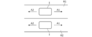
- FIG. 1 which is a plan view of a road
- the directions indicated by the arrow A1 (solid line) in the first lane R1 and the arrow A2 (solid line) in the second lane R2 are each predetermined regular progress.
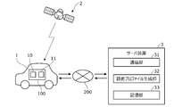
- FIG. 2 is a diagram showing an overall configuration of a reverse-way driving detection system having a reverse-way driving detection device according to the present embodiment.
- the reverse-way driving detection system includes an in-vehicle device 100 mounted on the vehicle 1 and a server device 3 capable of communicating with the in-vehicle device 100 via the network 200.
- the in-vehicle device 100 has a positioning sensor 10 that receives a positioning signal transmitted from the positioning satellite 2, and a communication unit 11 that communicates with the server device 3 via the network 200.
- the positioning satellite 2 is an artificial satellite such as a GPS satellite or a quasi-zenith satellite, and calculates the current position (latitude, longitude, altitude) of the vehicle 1 by using the positioning information from the positioning satellite 2 received by the positioning sensor 10. can do.
- the calculated current position is not always highly accurate, and it may be difficult to accurately identify the traveling lane only by the signal from the positioning sensor 10, that is, to detect reverse driving.
- the network 200 includes not only public wireless communication networks represented by Internet networks and mobile phone networks, but also closed communication networks provided for each predetermined management area, such as wireless LAN and Wi-Fi (registered trademark). , Bluetooth®, etc. are also included.
- the server device 3 is configured as, for example, a single server or a distributed server composed of separate servers for each function.
- the server device 3 can also be configured as a distributed virtual server created in a cloud environment called a cloud server.
- the server device 3 includes a CPU, a ROM, a RAM, and an arithmetic processing device having other peripheral circuits, and has a communication unit 31, a road surface profile generation unit 32, and a storage unit 33 as functional configurations. ..
- the communication unit 31 is configured to be capable of wireless communication with the in-vehicle device 100 via the network 200, and acquires the position information of the vehicle 1 and the traveling information of the vehicle 1 via the communication unit 11 of the vehicle 1, respectively.
- the position information is information indicating the current position of the vehicle 1 calculated by the signal received by the positioning sensor 10 of the vehicle 1.
- the traveling information is information indicating the traveling state of the vehicle 1 acquired by various sensors mounted on the vehicle 1.
- the traveling information includes information on the value detected by the acceleration sensor (lateral acceleration sensor) that detects the left-right acceleration (lateral acceleration) of the vehicle 1.
- the communication unit 31 constantly acquires not only the target vehicle (target vehicle) 1 for detecting reverse driving but also the position information and traveling information of a plurality of vehicles 1 other than the target vehicle.
- the road surface profile generation unit 32 generates a road surface profile showing road surface properties based on the position information and traveling information of a plurality of vehicles 1 other than the target vehicle acquired via the communication unit 31.
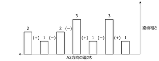
- the characteristic f1 of FIG. 3A is a diagram showing an example of a road surface profile.
- the horizontal axis in the figure is the position in the normal traveling direction of the vehicle 1, that is, the distance in the A1 direction in FIG. 1, and the vertical axis is the amount of unevenness (depth or height) of the road surface, that is, the road surface roughness. be.
- the road surface profile generation unit 32 calculates the amount of unevenness of the road surface corresponding to the vehicle position on the road from the lateral acceleration by using this predetermined correlation, and obtains the road surface profile in the traveling direction of the vehicle 1 as shown in FIG. 3A. Generate.
- the road surface profile generation unit 32 converts the characteristic f1 of the road surface profile into a digital value (integer value) represented by an integer such as 1, 2, ... For each predetermined distance as shown in FIG. 3A. That is, it is converted into a digital value such that the larger the unevenness amount, the larger the value.
- the road surface profile is represented by a list of digital values. For example, in the example of FIG. 3A, the road surface profile is represented by a list of digital values of "2 ⁇ 1 ⁇ 2 ⁇ 3 ⁇ 1 ⁇ 3 ⁇ 1".
- the road surface profile detected by the lateral acceleration sensor of each vehicle 1 may differ due to the different positions of the tires on the road surface.
- the road surface profile generation unit 32 averages each road surface profile detected by the lateral acceleration sensor of each vehicle 1, for example, and generates a representative road surface profile of each road surface.
- the road surface profile is represented by a list of digital values.
- the road surface profile generation unit 32 can also generate a road surface profile from the data obtained by driving a dedicated vehicle for measuring the road surface properties. For example, by running a dedicated vehicle equipped with a laser profiler and acquiring the measurement data at that time together with the position data of the dedicated vehicle, it is possible to generate a road surface profile without using a lateral acceleration sensor.
- the storage unit 33 stores a predetermined correlation between the road surface properties and the lateral acceleration used when the road surface profile is generated by the road surface profile generation unit 32, and also stores the road map information.
- Road map information includes road position information, road shape (curvature, etc.) information, road slope information, intersection and branch store position information, lane number information, lane width and lane-by-lane position information. Is done.
- the position information for each lane is information such as the center position of the lane and the boundary of the lane position.
- the road map information includes information on the road surface profile at each position of the road generated by the road surface profile generation unit 32, that is, information on the road surface profile represented by a list of digital values.
- the road surface profile information is updated every time the road surface profile generation unit 32 generates the road surface profile.
- Other road map information is updated at a predetermined cycle or at an arbitrary timing.
- the reverse driving of the vehicle 1 when the reverse driving of the vehicle 1 is detected, it is treated as if the road surface profile (reference road surface profile) at the traveling position of the vehicle 1 is already stored in the storage unit 33.
- FIG. 4 is a block diagram showing a functional configuration of the reverse run detection device 101 according to the present embodiment.
- the reverse run detection device 101 constitutes a part of the in-vehicle device 100 of FIG.
- the reverse-way driving detection device 101 includes a positioning sensor 10, a communication unit 11, a sensor group 13, a notification unit 14, and a controller 20.
- the positioning sensor 10, the communication unit 11, the sensor group 13, and the notification unit 14 are connected to the controller 20 so as to be communicable.
- the sensor group 13 is a general term for a plurality of sensors that detect the running state of the vehicle 1.
- the sensor group 13 includes a lateral acceleration sensor 131 that detects the left-right acceleration of the vehicle 1.
- the notification unit 14 is a device for notifying the driver of the vehicle 1 of predetermined information, and is composed of a monitor for displaying an image and a speaker for audio output.
- the controller 20 is an electronic control unit including a computer having a calculation unit such as a CPU, a storage unit such as a ROM and RAM, and other peripheral circuits.
- the calculation unit of the controller 20 has an information acquisition unit 21, a reverse run determination unit 25, and an output unit 26 as functional configurations.
- the information acquisition unit 21 has a position information acquisition unit 211, a traveling information acquisition unit 212, and a road map information acquisition unit 213. Similar to the storage unit 33 of the server device 3, the storage unit of the controller 20 has a predetermined correlation between the road surface properties used when the road surface profile is generated and the lateral acceleration, and a threshold value for making various determinations. Etc. are memorized.
- the position information acquisition unit 211 acquires the current position information of the vehicle 1 detected by the positioning sensor 10.
- the travel information acquisition unit 212 acquires travel information of the vehicle 1 including various detection values detected by the sensor group 13.
- the road map information acquisition unit 213 acquires road map information from the server device 3 via the communication unit 11. More specifically, the road map information acquisition unit 213 acquires road map information including the lane information of the road at the current position of the vehicle 1 detected by the positioning sensor 10 and the road surface profile information of each lane.
- the reverse running determination unit 25 is acquired by the current position information of the vehicle 1 acquired by the position information acquisition unit 211, the travel information of the vehicle 1 acquired by the travel information acquisition unit 212, and the road map information acquisition unit 213. Based on the road map information of the road on which the vehicle 1 is traveling, it is determined whether or not the vehicle 1 is traveling in the reverse direction. That is, it is determined whether or not the vehicle 1 is traveling in the lane R1 of FIG. 1 in the direction of the arrow A2, and whether or not the vehicle 1 is traveling in the lane R2 of FIG. 1 in the direction of the arrow A1.
- the amount of unevenness on the road surface is calculated from the lateral acceleration detected by the lateral acceleration sensor 131 by using the correlation between the road surface properties and the lateral acceleration stored in advance. If lateral acceleration is generated in vehicle 1 while the vehicle 1 is turning, the effect of the lateral acceleration is taken into consideration, that is, the amount is corrected, and the amount of unevenness on the road surface is calculated from the detected value of the lateral acceleration sensor 131. calculate. Then, a road surface profile showing a change in the amount of unevenness of the road surface along the traveling direction of the vehicle 1, that is, an actually measured road surface profile is generated. Next, the generated measured road surface profile is converted into a digital value (integer value) at predetermined distances as shown in FIG. 3A. As a result, the measured road surface profile is represented by a list of digital values, that is, a list of actually measured integer values.
- the reverse driving determination unit 25 determines the traveling direction of the vehicle 1 based on the signal from the positioning sensor 10. That is, by detecting the time-series position change of the vehicle 1, the traveling direction of the vehicle 1 is either the arrow A1 direction (referred to as the first direction) or the arrow A2 direction (referred to as the second direction) in FIG. Is determined.
- the traveling direction of the vehicle 1 is the first direction A1
- the first lane R1 in which the first direction A1 is the normal direction among the road surface profiles corresponding to the current position of the vehicle 1 included in the road map information.
- the degree of coincidence indicating the similarity between the road surface profile (referred to as the first reference road surface profile) and the actually measured road surface profile is calculated.
- the degree of coincidence is equal to or greater than a predetermined value, it is determined that the vehicle 1 is not running in the reverse direction, that is, the vehicle 1 is traveling in the first lane R1.
- the degree of coincidence is calculated by comparing the digital values indicating the road surface profile with each other. For example, the magnitudes of the digital values are compared with each other, and the degree of agreement is calculated according to the magnitude of the difference or the difference in the rate of change of the digital values.
- the reverse running determination unit 25 among the road surface profiles corresponding to the current position of the vehicle 1 included in the road map information, the second direction A2 opposite to the traveling direction (first direction A1) of the vehicle 1 is normal.
- the reverse running of the vehicle 1 is determined based on the road surface profile of the second lane R2 (referred to as the second reference road surface profile) and the actually measured road surface profile.
- the order of the list of digital values of the second reference road surface profile is reversed, and the second reference road surface profile is converted into a road surface profile for reverse-way driving determination.
- the second reference road surface profile is converted into a road surface profile for reverse-way driving determination.
- the converted road surface profile along the path of the second direction A2. Is "1 ⁇ 3 ⁇ 1 ⁇ 3 ⁇ 2 ⁇ 1 ⁇ 2" as shown in FIG. 3B.
- the reverse-way driving determination unit 25 compares the change in the digital value with the change in the digital value obtained from the actually measured road surface profile, and calculates the degree of matching of the road surface profile. Then, when the degree of coincidence is equal to or greater than a predetermined value, it is determined that the vehicle 1 is running in reverse. In this way, it is possible to easily and accurately determine the presence or absence of reverse driving by determining reverse driving based on the change (increase / decrease) of the digital value, that is, the continuity of the unevenness of the road surface, instead of the magnitude of the digital value. can. That is, the magnitude of the digital value is likely to vary (error), but the tendency of the increase / decrease of the digital value is unlikely to vary.
- the output unit 26 When the reverse-way driving determination unit 25 determines that the vehicle 1 is in reverse-way driving, the output unit 26 outputs an alarm signal to the notification unit 14. As a result, an alarm message is displayed on the monitor of the vehicle 1, or an alarm sound is output from the speaker. As a result, the driver can recognize that the vehicle 1 is running in the reverse direction.
- the output unit 26 transmits an alarm signal to the server device 3 via the communication unit 11, and the server device 3 faces another vehicle 1 around the target vehicle 1 or a road within a predetermined distance from the target vehicle 1. An alarm signal may be output to the display unit installed in the above. This makes it possible to alert the driver of the other vehicle 1.
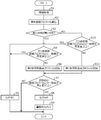
- FIG. 5 is a flowchart showing an example of processing executed by the controller 20 of FIG. 4 according to a predetermined program. The process shown in this flowchart is executed when the vehicle is running, and is repeated at a predetermined cycle.
- step S1 the current position information of the vehicle 1 detected by the positioning sensor 10, the traveling information of the vehicle 1 obtained by the sensor group 13, and the traveling road obtained via the communication unit 11 Get road map information.
- step S2 the measured road surface profile is calculated based on the detected value of the lateral acceleration sensor 131. As shown in FIG. 3A, the calculated measured road surface profile is represented by a list of digital values (measured integer values).
- step S3 it is determined whether or not the moving direction of the vehicle 1 is the first direction A1 in FIG. 1 based on the signal from the positioning sensor 10.
- step S3 the process proceeds to step S4, and the measured road surface profile calculated in step S2 and the first reference road surface profile corresponding to the current position of the vehicle 1, that is, the first lane R1 included in the road map information. It is determined whether or not the degree of agreement with the first reference road surface profile is equal to or higher than a predetermined value. Specifically, the degree of agreement is calculated by comparing the digital value representing the actually measured road surface profile with the digital value representing the first reference road surface profile.
- the predetermined value is a first predetermined value, and the first predetermined value is set to a value in the range of, for example, 50% to 80%. If affirmed in step S4, the process proceeds to step S5. In step S5, it is determined that the vehicle 1 is traveling in the first direction A1 along the first lane R1, and it is determined that the vehicle 1 does not run in the reverse direction, and the process ends.
- step S4 If denied in step S4, the process proceeds to step S6, and a second reference road surface profile corresponding to the current position of the vehicle 1, that is, a digital value representing the second reference road surface profile of the second lane R2 included in the road map information is obtained. , Convert to the value for reverse run judgment. More specifically, the enumeration of digital values of the second reference road surface profile is reversed, and the converted road surface profile which is an enumeration of codes represented by plus and minus signs for the increase / decrease of the digital value is generated.
- step S7 it is determined whether or not the degree of agreement between the actually measured road surface profile calculated in step S2 and the road surface profile generated in step S6 is equal to or higher than a predetermined value. That is, it is determined whether or not the change in the digital value representing the actually measured road surface profile matches the change in the digital value in step S6 to a predetermined degree or more.
- the predetermined value is a second predetermined value, and the second predetermined value is set to a value in the range of, for example, 50% to 80%.
- the second predetermined value may be set to a value larger than the first predetermined value in step S4, or the second predetermined value may be set to a value equal to the first predetermined value or smaller than the first predetermined value.
- step S8 it is determined that the vehicle 1 is traveling in the first direction A1 along the second lane R2. That is, it is determined that the vehicle 1 has a reverse run.
- step S9 an alarm signal is output to the notification unit 14, an alarm is generated from the monitor or speaker of the vehicle 1, and the process is completed.
- step S10 the actually measured road surface profile calculated in step S2 and the second reference road surface profile corresponding to the current position of the vehicle 1, that is, the second reference road surface profile of the second lane R2 included in the road map information. It is determined whether or not the degree of matching is equal to or higher than a predetermined value. Specifically, as in step S4, the degree of agreement is calculated by comparing the digital value representing the actually measured road surface profile with the digital value representing the second reference road surface profile. The predetermined value is equal to the first predetermined value in step S4.
- step S11 the digital value representing the first reference road surface profile corresponding to the current position of the vehicle 1, that is, the first reference road surface profile of the first lane R1 included in the road map information is used as the value for determining reverse driving. Convert. More specifically, the list of digital values of the first reference road surface profile is reversed, and the converted road surface profile, which is a list of codes represented by plus and minus signs for the increase and decrease of the digital values, is generated. Then, the process proceeds to step S7.
- FIG. 6 is a diagram schematically showing the state of the vehicle 1 traveling along the first lane R1 by the tire 1a, and the road surface shape is represented by the digital value of the first reference road surface profile.
- the vehicle 1 travels in the first direction A1
- the actually measured road surface profile and the first reference road surface profile are compared (step S4).
- the degree of coincidence is equal to or greater than a predetermined value, it is determined that there is no reverse driving (step S5).
- step S10 it is determined whether or not the degree of coincidence between the actually measured road surface profile and the second reference road surface profile is equal to or higher than a predetermined value.
- the degree of coincidence since the degree of coincidence is not equal to or higher than the predetermined value, the change in the first reference road surface profile after conversion by reversing the enumeration of the digital values of the first reference road surface profile is compared with the change in the actually measured road surface profile (Ste S11 ⁇ Step S7). Then, when the degree of coincidence is equal to or higher than a predetermined value, it is determined that there is a reverse run, and an alarm signal is output (step S8, step S9).
- the reverse running detection device 101 is used for the position information acquisition unit 211 that acquires the position information of the current position of the vehicle 1 obtained by the positioning sensor 10 that positions the vehicle 1 and the road surface profile of the road surface on which the vehicle 1 travels.
- the driving information acquisition unit 212 that acquires the driving information of the vehicle 1 including the information of the sensor value of the lateral acceleration sensor 131 that changes accordingly, and the road map that acquires the road map information including the lane information and the road surface profile information of the road. Based on the position information acquired by the information acquisition unit 213, the position information acquisition unit 211, the travel information acquired by the travel information acquisition unit 212, and the road map information acquired by the road map information acquisition unit 213.
- a reverse travel determination unit 25 for determining reverse travel of the vehicle 1 is provided (FIG. 4).
- the road map information acquired by the road map information acquisition unit 213 includes a first reference road surface profile which is a road surface profile of the first lane R1 whose traveling direction is defined in the first direction A1 and a traveling direction of the first direction.
- the reverse running determination unit 25 obtains an actually measured road surface profile on the road surface on which the vehicle 1 is traveling based on the lateral acceleration information acquired by the traveling information acquisition unit 212, and obtains the position information acquired by the position information acquisition unit 211.
- the traveling direction of the vehicle 1 When the traveling direction of the vehicle 1 is determined based on the above and it is determined that the traveling direction of the vehicle 1 is the first direction A1, it corresponds to the measured road surface profile and the current position of the vehicle 1 acquired by the position information acquisition unit 211. It is further determined whether or not the degree of agreement with the first reference road surface profile is equal to or greater than the first predetermined value, and it is determined that the degree of agreement between the actually measured road surface profile and the first reference road surface profile is less than the first predetermined value. And, based on the actually measured road surface profile and the second reference road surface profile corresponding to the current position of the vehicle 1 acquired by the position information acquisition unit 211, the reverse running of the vehicle 1 is determined (FIG. 5).
- the reverse drive of the vehicle 1 can be detected at low cost as a whole. Further, since the reverse driving of the vehicle 1 is detected based on the road surface profile, it is not necessary to accurately detect the lane, and it is sufficient that the rough position of the vehicle 1 can be detected. That is, it is not necessary to detect whether the currently traveling lane is the first lane R1 or the second lane R2. Therefore, the high-precision positioning sensor 10 is not required, and the device can be inexpensively configured in this respect as well.
- the reverse driving determination unit 25 uses the second reference road surface profile as the reference road surface in the reverse driving direction.
- the reverse driving of vehicle 1 is determined based on the degree of agreement between the converted reference road surface profile and the actually measured road surface profile (FIG. 5).
- the reverse run can be accurately determined. That is, in the present embodiment, attention is paid to the fact that the road surface profiles are different from each other in the normal direction and the reverse driving direction, and the presence or absence of the reverse driving is determined based on the degree of matching of the road surface profiles in each direction. It is possible to accurately detect the reverse run of.
- the reverse-way driving determination unit 25 calculates the degree of coincidence between the first reference road surface profile and the actually measured road surface profile based on the magnitude of the unevenness amount of the road surface, and after conversion based on the change in the unevenness amount of the road surface. Calculate the degree of agreement between the reference road surface profile and the measured road surface profile. That is, the determination in the normal direction and the determination in the reverse driving direction are performed by different methods. As a result, the reverse driving of the vehicle 1 can be detected efficiently and accurately.
- the reverse-way driving detection device 101 further includes an output unit 26 that outputs an alarm signal when the reverse-way driving determination unit 25 determines that the vehicle 1 is in reverse-way driving (FIG. 4). As a result, it is possible to notify the driver or the like that the vehicle 1 is running in reverse.
- the reverse-way driving detection device 101 of the present embodiment can also be used as a reverse-way driving detection method.
- the reverse running detection method the position information of the current position of the vehicle 1 obtained by the positioning sensor 10 for positioning the vehicle 1 and the sensor value of the lateral acceleration sensor 131 that changes according to the road surface profile of the road surface on which the vehicle 1 travels.
- a step of determining the reverse running of the vehicle 1 based on the information and the step of determining the reverse running of the vehicle 1 are executed by a computer (FIG. 5).
- the acquired road map information includes a first reference road surface profile, which is a road surface profile of the first lane R1 whose traveling direction is defined in the first direction A1, and a second direction opposite to the first direction A1.
- a second reference road surface profile which is a road surface profile of the second lane R2 defined in A2, is included (FIG. 1).
- the measured road surface profile on the road surface on which the vehicle 1 is traveling is obtained based on the acquired sensor value information, and the traveling direction of the vehicle 1 is determined based on the acquired position information.
- step S3 When the determination is made (step S3) and it is determined that the traveling direction of the vehicle 1 is the first direction A1, the degree of agreement between the actually measured road surface profile and the acquired first reference road surface profile corresponding to the current position of the vehicle 1 is determined. Further determines whether or not is equal to or greater than a predetermined value (step S4), and when it is determined that the degree of agreement between the actually measured road surface profile and the first reference road surface profile is less than the predetermined value, the actually measured road surface profile and the acquired vehicle are determined.
- the reverse driving of the vehicle 1 is determined based on the second reference road surface profile corresponding to the current position of 1 (step S7, step S8). As a result, it is possible to detect the reverse driving of the vehicle 1 with an inexpensive configuration.
- the travel information acquisition unit 212 acquires the travel information of the vehicle 1 including the information of the detection value (sensor value) of the lateral acceleration sensor 131, but other vehicles that change according to the road surface profile. Travel information including information on the detection value of the detector may be acquired. For example, information on the detection value of the sensor that detects the acceleration in the front-rear direction (front-back acceleration) of the vehicle 1, the detection value of the sensor that detects the roll angle and roll rate, and the detection value of the sensor that detects the vibration of the vehicle in the up-down direction.
- the traveling information acquisition unit may acquire the traveling information including the above.
- whether or not the vehicle 1 is traveling in the normal direction is determined based on the size of the digital value (integer) representing the road surface profile, and whether or not the vehicle 1 is traveling in the reverse direction. Is determined based on the change in the digital value (integer) representing the road surface profile, but these determination methods are not limited to those described above. For example, it may be determined whether or not the vehicle 1 is traveling in the normal direction based on the change in the digital value representing the road surface profile, and whether or not the vehicle 1 is traveling in the reverse direction may be determined. The determination may be made based on the magnitude of the digital value representing the road surface profile.
- the reverse-way driving detection device 101 is mounted on the vehicle 1, but a part or all of the functions of the reverse-way driving detection device 101 may be provided on the server device 3.
- the positioning sensor 10 that receives the positioning signal transmitted from the positioning satellite 2 is mounted on the vehicle 1, but the positioning sensor 10 measures the vehicle position by another method, for example, self-contained navigation. There may be. That is, the positioning sensor is not limited to the one that receives the signal transmitted from the positioning satellite to position the vehicle.
Landscapes
- Engineering & Computer Science (AREA)
- Automation & Control Theory (AREA)
- Physics & Mathematics (AREA)
- Transportation (AREA)
- Mechanical Engineering (AREA)
- Mathematical Physics (AREA)
- General Physics & Mathematics (AREA)
- Human Computer Interaction (AREA)
- Aviation & Aerospace Engineering (AREA)
- Radar, Positioning & Navigation (AREA)
- Remote Sensing (AREA)
- Traffic Control Systems (AREA)
Abstract
A wrong-way driving detecting device (101): obtains an actually measured road surface profile of a road surface along which a vehicle is traveling, and determines the direction of progress of the vehicle on the basis of position information of the vehicle; if it is determined that the direction of progress of the vehicle is a first direction, additionally determines whether the degree of coincidence of the actually measured road surface profile and a first reference road surface profile of a first lane corresponding to the current position of the vehicle is at least equal to a prescribed value; and if it is determined that the degree of coincidence of the actually measured road surface profile and the first reference road surface profile is less than the prescribed value, determines whether the vehicle is traveling the wrong way, on the basis of the actually measured road surface profile and a second reference road surface profile of a second lane corresponding to the current position of the vehicle.
Description
本発明は、車両の逆走を検出する逆走検出装置および逆走検出方法に関する。
The present invention relates to a reverse-way driving detection device for detecting reverse-way driving of a vehicle and a reverse-way driving detection method.
この種の装置として、従来、道路に設置されたカメラによって所定のフレーム周期で車両を撮像し、これにより車両の逆走を検出するようにした装置が知られている(例えば特許文献1参照)。特許文献1記載の装置では、カメラにより撮像された現フレームのナンバープレートの位置情報と1フレーム前のナンバープレートの位置情報とを比較し、ナンバープレートの移動方向に基づいて車両の逆走を判断する。
As a device of this type, conventionally, a device is known in which a camera installed on a road captures an image of a vehicle at a predetermined frame cycle and thereby detects a reverse-way driving of the vehicle (see, for example, Patent Document 1). .. In the apparatus described in Patent Document 1, the position information of the license plate of the current frame captured by the camera is compared with the position information of the license plate one frame before, and the reverse running of the vehicle is determined based on the moving direction of the license plate. do.
しかしながら、上記特許文献1記載の装置では、多くの道路で逆走を検出する場合に、全体として多数のカメラが必要となり、コストの上昇を招きやすい。
However, the device described in Patent Document 1 requires a large number of cameras as a whole when detecting reverse driving on many roads, which tends to increase the cost.
本発明の一態様である逆走検出装置は、車両を測位する測位センサにより得られた車両の現在位置の位置情報を取得する位置情報取得部と、車両が走行する路面の路面プロファイルに応じて変化する検出器の検出値の情報を含む車両の走行情報を取得する走行情報取得部と、道路の車線情報と路面プロファイルの情報とを含む道路地図情報を取得する道路地図情報取得部と、位置情報取得部により取得された位置情報と、走行情報取得部により取得された走行情報と、道路地図情報取得部により取得された道路地図情報とに基づいて、車両の逆走を判定する逆走判定部と、を備える。道路地図情報取得部により取得された道路地図情報には、進行方向が第1方向に規定された第1車線の路面プロファイルである第1参照用路面プロファイルと、進行方向が第1方向の反対の第2方向に規定された第2車線の路面プロファイルである第2参照用路面プロファイルとが含まれる。逆走判定部は、走行情報取得部により取得された検出器の検出値の情報に基づいて車両が走行中の路面における実測路面プロファイルを求めるとともに、位置情報取得部により取得された位置情報に基づいて車両の進行方向を判定し、車両の進行方向が第1方向であると判定されると、実測路面プロファイルと位置情報取得部により取得された車両の現在位置に対応する第1参照用路面プロファイルとの一致度が所定値以上であるか否かをさらに判定し、実測路面プロファイルと第1参照用路面プロファイルとの一致度が所定値未満と判定されると、実測路面プロファイルと位置情報取得部により取得された車両の現在位置に対応する第2参照用路面プロファイルとに基づいて、車両の逆走を判定する。
The reverse running detection device according to one aspect of the present invention corresponds to a position information acquisition unit that acquires position information of the current position of the vehicle obtained by a positioning sensor that positions the vehicle and a road surface profile of the road surface on which the vehicle travels. A driving information acquisition unit that acquires vehicle driving information including information on the detection value of a changing detector, a road map information acquisition unit that acquires road map information including road lane information and road surface profile information, and a position. Reverse running judgment to determine reverse running of a vehicle based on the position information acquired by the information acquisition unit, the driving information acquired by the driving information acquisition unit, and the road map information acquired by the road map information acquisition unit. It is equipped with a department. The road map information acquired by the road map information acquisition unit includes the first reference road surface profile, which is the road surface profile of the first lane in which the traveling direction is defined in the first direction, and the opposite of the traveling direction in the first direction. A second reference road surface profile, which is a road surface profile of the second lane defined in the second direction, is included. The reverse-way driving determination unit obtains an actually measured road surface profile on the road surface on which the vehicle is traveling based on the information of the detection value of the detector acquired by the driving information acquisition unit, and is based on the position information acquired by the position information acquisition unit. When the traveling direction of the vehicle is determined and the traveling direction of the vehicle is determined to be the first direction, the measured road surface profile and the first reference road surface profile corresponding to the current position of the vehicle acquired by the position information acquisition unit are used. It is further determined whether or not the degree of agreement with is equal to or more than a predetermined value, and when it is determined that the degree of agreement between the actually measured road surface profile and the first reference road surface profile is less than the predetermined value, the actually measured road surface profile and the position information acquisition unit Based on the second reference road surface profile corresponding to the current position of the vehicle acquired by the above, the reverse driving of the vehicle is determined.
本発明の他の態様である逆走検出方法は、車両を測位する測位センサにより得られた車両の現在位置の位置情報を取得するステップと、車両が走行する路面の路面プロファイルに応じて変化する検出器の検出値の情報を含む車両の走行情報を取得するステップと、道路の車線情報と路面プロファイルの情報とを含む道路地図情報を取得するステップと、取得された位置情報と走行情報と道路地図情報とに基づいて、車両の逆走を判定するステップと、をコンピュータにより実行することを含む。取得された道路地図情報には、進行方向が第1方向に規定された第1車線の路面プロファイルである第1参照用路面プロファイルと、進行方向が第1方向の反対の第2方向に規定された第2車線の路面プロファイルである第2参照用路面プロファイルとが含まれる。車両の逆走を判定するステップは、取得された検出値の情報に基づいて車両が走行中の路面における実測路面プロファイルを求めるとともに、取得された位置情報に基づいて車両の進行方向を判定し、車両の進行方向が第1方向であると判定されると、実測路面プロファイルと取得された車両の現在位置に対応する第1参照用路面プロファイルとの一致度が所定値以上であるか否かをさらに判定し、実測路面プロファイルと第1参照用路面プロファイルとの一致度が所定値未満と判定されると、実測路面プロファイルと取得された車両の現在位置に対応する第2参照用路面プロファイルとに基づいて、車両の逆走を判定することを含む。
The reverse running detection method, which is another aspect of the present invention, changes according to the step of acquiring the position information of the current position of the vehicle obtained by the positioning sensor for positioning the vehicle and the road surface profile of the road surface on which the vehicle travels. A step to acquire vehicle driving information including information on the detection value of the detector, a step to acquire road map information including road lane information and road surface profile information, and a step to acquire acquired position information, driving information, and road. The step of determining the reverse running of the vehicle based on the map information and the execution by the computer are included. In the acquired road map information, the first reference road surface profile, which is the road surface profile of the first lane in which the traveling direction is defined in the first direction, and the traveling direction are defined in the second direction opposite to the first direction. A second reference road surface profile, which is a road surface profile of the second lane, is included. In the step of determining the reverse driving of the vehicle, the measured road surface profile on the road surface on which the vehicle is traveling is obtained based on the acquired detection value information, and the traveling direction of the vehicle is determined based on the acquired position information. When it is determined that the traveling direction of the vehicle is the first direction, it is determined whether or not the degree of agreement between the actually measured road surface profile and the acquired first reference road surface profile corresponding to the current position of the vehicle is equal to or higher than a predetermined value. Further, when it is determined that the degree of agreement between the actually measured road surface profile and the first reference road surface profile is less than a predetermined value, the actually measured road surface profile and the second reference road surface profile corresponding to the acquired current position of the vehicle are obtained. Including determining the reverse driving of the vehicle based on.
本発明によれば、安価な構成で車両の逆走を検出することができる。
According to the present invention, it is possible to detect reverse driving of a vehicle with an inexpensive configuration.
以下、図1~図6を参照して本発明の実施形態について説明する。本発明の実施形態に係る逆走検出装置は、ドライバの勘違いや注意不足等を原因として、道路を正規の走行方向とは逆方向に走行する逆走を検出する装置である。例えば道路の平面図である図1に示すように、第1車線R1内の矢印A1(実線)および第2車線R2内の矢印A2(実線)で示す方向が、それぞれ予め規定された正規の進行方向(正規方向)であり、第1車線R1内の矢印A2(点線)および第2車線R2内の矢印A1(点線)で示す方向が、車両1が逆走するときの進行方向(逆走方向)である。
Hereinafter, embodiments of the present invention will be described with reference to FIGS. 1 to 6. The reverse-way driving detection device according to the embodiment of the present invention is a device that detects reverse-way driving traveling on a road in a direction opposite to the normal traveling direction due to a driver's misunderstanding, lack of attention, or the like. For example, as shown in FIG. 1, which is a plan view of a road, the directions indicated by the arrow A1 (solid line) in the first lane R1 and the arrow A2 (solid line) in the second lane R2 are each predetermined regular progress. The direction (normal direction), which is the direction indicated by the arrow A2 (dotted line) in the first lane R1 and the arrow A1 (dotted line) in the second lane R2, is the traveling direction (reverse running direction) when the vehicle 1 runs in the reverse direction. ).
図2は、本実施形態に係る逆走検出装置を有する逆走検出システムの全体構成を示す図である。図2に示すように、逆走検出システムは、車両1に搭載された車載装置100と、ネットワーク200を介して車載装置100と通信可能なサーバ装置3とを有する。
FIG. 2 is a diagram showing an overall configuration of a reverse-way driving detection system having a reverse-way driving detection device according to the present embodiment. As shown in FIG. 2, the reverse-way driving detection system includes an in-vehicle device 100 mounted on the vehicle 1 and a server device 3 capable of communicating with the in-vehicle device 100 via the network 200.
車載装置100は、測位衛星2から送信された測位用の信号を受信する測位センサ10と、ネットワーク200を介してサーバ装置3と通信する通信ユニット11とを有する。測位衛星2は、GPS衛星や準天頂衛星などの人工衛星であり、測位センサ10が受信した測位衛星2からの測位情報を利用して、車両1の現在位置(緯度、経度、高度)を算出することができる。なお、算出された現在位置は高精度であるとは限らず、測位センサ10からの信号のみで走行車線を精度よく特定すること、つまり逆走を検出することは困難な場合がある。
The in-vehicle device 100 has a positioning sensor 10 that receives a positioning signal transmitted from the positioning satellite 2, and a communication unit 11 that communicates with the server device 3 via the network 200. The positioning satellite 2 is an artificial satellite such as a GPS satellite or a quasi-zenith satellite, and calculates the current position (latitude, longitude, altitude) of the vehicle 1 by using the positioning information from the positioning satellite 2 received by the positioning sensor 10. can do. The calculated current position is not always highly accurate, and it may be difficult to accurately identify the traveling lane only by the signal from the positioning sensor 10, that is, to detect reverse driving.
ネットワーク200には、インターネット網や携帯電話網等に代表される公衆無線通信網だけでなく、所定の管理地域ごとに設けられた閉鎖的な通信網、例えば無線LAN、Wi-Fi(登録商標)、Bluetooth(登録商標)等も含まれる。サーバ装置3は、例えば単一のサーバとして、あるいは機能ごとに別々のサーバから構成される分散サーバとして構成される。クラウドサーバと呼ばれるクラウド環境に作られた分散型の仮想サーバとしてサーバ装置3を構成することもできる。
The network 200 includes not only public wireless communication networks represented by Internet networks and mobile phone networks, but also closed communication networks provided for each predetermined management area, such as wireless LAN and Wi-Fi (registered trademark). , Bluetooth®, etc. are also included. The server device 3 is configured as, for example, a single server or a distributed server composed of separate servers for each function. The server device 3 can also be configured as a distributed virtual server created in a cloud environment called a cloud server.
サーバ装置3は、CPU,ROM,RAM、およびその他の周辺回路を有する演算処理装置を含んで構成され、機能的構成として、通信部31と、路面プロファイル生成部32と、記憶部33とを有する。
The server device 3 includes a CPU, a ROM, a RAM, and an arithmetic processing device having other peripheral circuits, and has a communication unit 31, a road surface profile generation unit 32, and a storage unit 33 as functional configurations. ..
通信部31は、ネットワーク200を介し車載装置100と無線通信可能に構成され、車両1の位置情報と、車両1の走行情報とを、車両1の通信ユニット11を介してそれぞれ取得する。位置情報は、車両1の測位センサ10が受信した信号によって算出された車両1の現在位置を示す情報である。走行情報は、車両1に搭載された各種センサにより取得された車両1の走行状態を示す情報である。走行情報には、車両1の左右方向の加速度(横加速度)を検出する加速度センサ(横加速度センサ)による検出値の情報が含まれる。通信部31は、逆走を検出する対象となる車両(対象車両)1だけでなく、対象車両以外の複数の車両1の位置情報と走行情報とを常時取得する。
The communication unit 31 is configured to be capable of wireless communication with the in-vehicle device 100 via the network 200, and acquires the position information of the vehicle 1 and the traveling information of the vehicle 1 via the communication unit 11 of the vehicle 1, respectively. The position information is information indicating the current position of the vehicle 1 calculated by the signal received by the positioning sensor 10 of the vehicle 1. The traveling information is information indicating the traveling state of the vehicle 1 acquired by various sensors mounted on the vehicle 1. The traveling information includes information on the value detected by the acceleration sensor (lateral acceleration sensor) that detects the left-right acceleration (lateral acceleration) of the vehicle 1. The communication unit 31 constantly acquires not only the target vehicle (target vehicle) 1 for detecting reverse driving but also the position information and traveling information of a plurality of vehicles 1 other than the target vehicle.
路面プロファイル生成部32は、通信部31を介して取得された対象車両以外の複数の車両1の位置情報と走行情報とに基づいて、路面性状を示す路面プロファイルを生成する。図3Aの特性f1は、路面プロファイルの一例を示す図である。図中の横軸は、車両1の正規の進行方向の位置、つまり図1のA1方向の道のりであり、縦軸は、路面の凹凸の量(深さまたは高さ)、つまり路面粗さである。
The road surface profile generation unit 32 generates a road surface profile showing road surface properties based on the position information and traveling information of a plurality of vehicles 1 other than the target vehicle acquired via the communication unit 31. The characteristic f1 of FIG. 3A is a diagram showing an example of a road surface profile. The horizontal axis in the figure is the position in the normal traveling direction of the vehicle 1, that is, the distance in the A1 direction in FIG. 1, and the vertical axis is the amount of unevenness (depth or height) of the road surface, that is, the road surface roughness. be.
一般に、路面の凹凸の量が大きいほど車両1の横加速度は大きい。したがって、路面性状と横加速度とは所定の相関関係を有する。路面プロファイル生成部32は、この所定の相関関係を用いて、横加速度から道路上の車両位置に対応する路面の凹凸量を算出し、図3Aに示すように車両1の進行方向における路面プロファイルを生成する。
Generally, the larger the amount of unevenness on the road surface, the larger the lateral acceleration of vehicle 1. Therefore, the road surface property and the lateral acceleration have a predetermined correlation. The road surface profile generation unit 32 calculates the amount of unevenness of the road surface corresponding to the vehicle position on the road from the lateral acceleration by using this predetermined correlation, and obtains the road surface profile in the traveling direction of the vehicle 1 as shown in FIG. 3A. Generate.
さらに、路面プロファイル生成部32は、路面プロファイルの特性f1を、図3Aに示すように所定距離毎に例えば1,2・・等の整数によって表されるデジタル値(整数値)に変換する。すなわち、凹凸量が大きいほど大きな値となるようなデジタル値に変換する。これにより、路面プロファイルがデジタル値の羅列によって表される。例えば図3Aの例では、「2→1→2→3→1→3→1」のデジタル値の羅列によって路面プロファイルが表される。
Further, the road surface profile generation unit 32 converts the characteristic f1 of the road surface profile into a digital value (integer value) represented by an integer such as 1, 2, ... For each predetermined distance as shown in FIG. 3A. That is, it is converted into a digital value such that the larger the unevenness amount, the larger the value. As a result, the road surface profile is represented by a list of digital values. For example, in the example of FIG. 3A, the road surface profile is represented by a list of digital values of "2 → 1 → 2 → 3 → 1 → 3 → 1".
同一車線を異なる車両1が走行する場合に、路面上のタイヤの位置が異なることにより、各車両1の横加速度センサにより検出された路面プロファイルが異なることがある。この場合、路面プロファイル生成部32は、例えば各車両1の横加速度センサにより検出されたそれぞれの路面プロファイルを平均化して、各路面の代表的な路面プロファイルを生成する。この場合もデジタル値の羅列によって路面プロファイルが表される。
When different vehicles 1 travel in the same lane, the road surface profile detected by the lateral acceleration sensor of each vehicle 1 may differ due to the different positions of the tires on the road surface. In this case, the road surface profile generation unit 32 averages each road surface profile detected by the lateral acceleration sensor of each vehicle 1, for example, and generates a representative road surface profile of each road surface. In this case as well, the road surface profile is represented by a list of digital values.
路面プロファイル生成部32は、路面性状の測定用の専用車両を走行させることにより得られたデータから、路面プロファイルを生成することもできる。例えばレーザプロファイラを搭載した専用車両を走行させ、そのときの測定データを、専用車両の位置データとともに取得することで、横加速度センサを用いることなく路面プロファイルを生成することもできる。
The road surface profile generation unit 32 can also generate a road surface profile from the data obtained by driving a dedicated vehicle for measuring the road surface properties. For example, by running a dedicated vehicle equipped with a laser profiler and acquiring the measurement data at that time together with the position data of the dedicated vehicle, it is possible to generate a road surface profile without using a lateral acceleration sensor.
記憶部33は、路面プロファイル生成部32により路面プロファイルが生成されるときに用いられる路面性状と横加速度との間の所定の相関関係を記憶するとともに、道路地図情報を記憶する。道路地図情報には、道路の位置情報、道路形状(曲率など)の情報、道路の勾配の情報、交差点や分岐店の位置情報、車線数の情報、車線の幅員および車線毎の位置情報が含まれる。車線毎の位置情報とは、車線の中央位置や車線位置の境界の情報などである。さらに道路地図情報には、路面プロファイル生成部32により生成された道路の各位置での路面プロファイルの情報、すなわちデジタル値の羅列によって表される路面プロファイルの情報が含まれる。
The storage unit 33 stores a predetermined correlation between the road surface properties and the lateral acceleration used when the road surface profile is generated by the road surface profile generation unit 32, and also stores the road map information. Road map information includes road position information, road shape (curvature, etc.) information, road slope information, intersection and branch store position information, lane number information, lane width and lane-by-lane position information. Is done. The position information for each lane is information such as the center position of the lane and the boundary of the lane position. Further, the road map information includes information on the road surface profile at each position of the road generated by the road surface profile generation unit 32, that is, information on the road surface profile represented by a list of digital values.
記憶部33に記憶される道路地図情報のうち、路面プロファイルの情報は、路面プロファイル生成部32により路面プロファイルが生成される度に更新される。他の道路地図情報は、所定周期で、あるいは任意のタイミングで更新される。なお、本実施形態では、車両1の逆走を検出する場合、車両1の走行位置における路面プロファイル(参照用路面プロファイル)が既に記憶部33に記憶されているものとして扱う。
Of the road map information stored in the storage unit 33, the road surface profile information is updated every time the road surface profile generation unit 32 generates the road surface profile. Other road map information is updated at a predetermined cycle or at an arbitrary timing. In the present embodiment, when the reverse driving of the vehicle 1 is detected, it is treated as if the road surface profile (reference road surface profile) at the traveling position of the vehicle 1 is already stored in the storage unit 33.
図4は、本実施形態に係る逆走検出装置101の機能的構成を示すブロック図である。逆走検出装置101は、図1の車載装置100の一部を構成する。図4に示すように、逆走検出装置101は、測位センサ10と、通信ユニット11と、センサ群13と、報知部14と、コントローラ20とを備える。測位センサ10と通信ユニット11とセンサ群13と報知部14とは、それぞれコントローラ20に通信可能に接続される。
FIG. 4 is a block diagram showing a functional configuration of the reverse run detection device 101 according to the present embodiment. The reverse run detection device 101 constitutes a part of the in-vehicle device 100 of FIG. As shown in FIG. 4, the reverse-way driving detection device 101 includes a positioning sensor 10, a communication unit 11, a sensor group 13, a notification unit 14, and a controller 20. The positioning sensor 10, the communication unit 11, the sensor group 13, and the notification unit 14 are connected to the controller 20 so as to be communicable.
センサ群13は、車両1の走行状態を検出する複数のセンサの総称である。センサ群13には、車両1の左右方向の加速度を検出する横加速度センサ131が含まれる。報知部14は、車両1のドライバに所定情報を報知するための機器であり、画像表示用のモニタや音声出力用のスピーカにより構成される。
The sensor group 13 is a general term for a plurality of sensors that detect the running state of the vehicle 1. The sensor group 13 includes a lateral acceleration sensor 131 that detects the left-right acceleration of the vehicle 1. The notification unit 14 is a device for notifying the driver of the vehicle 1 of predetermined information, and is composed of a monitor for displaying an image and a speaker for audio output.
コントローラ20は、CPU等の演算部と、ROM,RAM等の記憶部と、その他の周辺回路とを有するコンピュータを含んで構成される電子制御ユニットである。コントローラ20の演算部は、機能的構成として、情報取得部21と、逆走判定部25と、出力部26とを有する。情報取得部21は、位置情報取得部211と、走行情報取得部212と、道路地図情報取得部213とを有する。コントローラ20の記憶部には、サーバ装置3の記憶部33と同様、路面プロファイルが生成されるときに用いられる路面性状と横加速度との間の所定の相関関係や、各種判定を行う場合の閾値などが記憶される。
The controller 20 is an electronic control unit including a computer having a calculation unit such as a CPU, a storage unit such as a ROM and RAM, and other peripheral circuits. The calculation unit of the controller 20 has an information acquisition unit 21, a reverse run determination unit 25, and an output unit 26 as functional configurations. The information acquisition unit 21 has a position information acquisition unit 211, a traveling information acquisition unit 212, and a road map information acquisition unit 213. Similar to the storage unit 33 of the server device 3, the storage unit of the controller 20 has a predetermined correlation between the road surface properties used when the road surface profile is generated and the lateral acceleration, and a threshold value for making various determinations. Etc. are memorized.
位置情報取得部211は、測位センサ10により検出された車両1の現在の位置情報を取得する。走行情報取得部212は、センサ群13により検出された各種検出値を含む車両1の走行情報を取得する。道路地図情報取得部213は、通信ユニット11を介してサーバ装置3から道路地図情報を取得する。より詳しくは、道路地図情報取得部213は、測位センサ10により検出された車両1の現在位置における道路の車線情報と、各車線の路面プロファイルの情報とを含む道路地図情報を取得する。
The position information acquisition unit 211 acquires the current position information of the vehicle 1 detected by the positioning sensor 10. The travel information acquisition unit 212 acquires travel information of the vehicle 1 including various detection values detected by the sensor group 13. The road map information acquisition unit 213 acquires road map information from the server device 3 via the communication unit 11. More specifically, the road map information acquisition unit 213 acquires road map information including the lane information of the road at the current position of the vehicle 1 detected by the positioning sensor 10 and the road surface profile information of each lane.
逆走判定部25は、位置情報取得部211により取得された車両1の現在の位置情報と、走行情報取得部212により取得された車両1の走行情報と、道路地図情報取得部213により取得された車両1の走行中の道路の道路地図情報とに基づいて、車両1が逆走しているか否かを判定する。すなわち、車両1が図1の車線R1を矢印A2方向に走行しているか否か、および図1の車線R2を矢印A1方向に走行しているか否かを判定する。
The reverse running determination unit 25 is acquired by the current position information of the vehicle 1 acquired by the position information acquisition unit 211, the travel information of the vehicle 1 acquired by the travel information acquisition unit 212, and the road map information acquisition unit 213. Based on the road map information of the road on which the vehicle 1 is traveling, it is determined whether or not the vehicle 1 is traveling in the reverse direction. That is, it is determined whether or not the vehicle 1 is traveling in the lane R1 of FIG. 1 in the direction of the arrow A2, and whether or not the vehicle 1 is traveling in the lane R2 of FIG. 1 in the direction of the arrow A1.
この場合、まず、予め記憶された路面性状と横加速度との相関関係を用いて、横加速度センサ131により検出された横加速度から路面の凹凸量を算出する。なお、車両1が旋回走行中等で車両1に横加速度が生じている場合には、その影響を考慮して、すなわちその分を補正して、横加速度センサ131の検出値から路面の凹凸量を算出する。そして、車両1の進行方向に沿った路面の凹凸量の変化を表す路面プロファイル、すなわち実測路面プロファイルを生成する。次いで、生成された実測路面プロファイルを図3Aに示すように所定距離毎にデジタル値(整数値)に変換する。これにより、デジタル値の羅列、すなわち実測整数値の羅列によって実測路面プロファイルが表される。
In this case, first, the amount of unevenness on the road surface is calculated from the lateral acceleration detected by the lateral acceleration sensor 131 by using the correlation between the road surface properties and the lateral acceleration stored in advance. If lateral acceleration is generated in vehicle 1 while the vehicle 1 is turning, the effect of the lateral acceleration is taken into consideration, that is, the amount is corrected, and the amount of unevenness on the road surface is calculated from the detected value of the lateral acceleration sensor 131. calculate. Then, a road surface profile showing a change in the amount of unevenness of the road surface along the traveling direction of the vehicle 1, that is, an actually measured road surface profile is generated. Next, the generated measured road surface profile is converted into a digital value (integer value) at predetermined distances as shown in FIG. 3A. As a result, the measured road surface profile is represented by a list of digital values, that is, a list of actually measured integer values.
さらに、逆走判定部25は、測位センサ10からの信号に基づいて車両1の進行方向を判定する。すなわち、車両1の時系列の位置変化を検出することで、車両1の進行方向が図1の矢印A1方向(第1方向と呼ぶ)および矢印A2方向(第2方向と呼ぶ)のいずれであるかを判定する。車両1の進行方向が第1方向A1であると判定されると、道路地図情報に含まれる車両1の現在位置に対応する路面プロファイルのうち、第1方向A1が正規方向である第1車線R1の路面プロファイル(第1参照用路面プロファイルと呼ぶ)と、実測路面プロファイルとの類似性を示す一致度を算出する。そして、一致度が所定値以上であるとき、車両1が逆走ではない、すなわち車両1は第1車線R1を走行していると判定する。一致度の算出は、路面プロファイルを示すデジタル値同士を比較して行う。例えば、デジタル値の大きさを互いに比較し、その差の大小に応じて、またはデジタル値の変化率の違いに応じて、一致度を算出する。
Further, the reverse driving determination unit 25 determines the traveling direction of the vehicle 1 based on the signal from the positioning sensor 10. That is, by detecting the time-series position change of the vehicle 1, the traveling direction of the vehicle 1 is either the arrow A1 direction (referred to as the first direction) or the arrow A2 direction (referred to as the second direction) in FIG. Is determined. When it is determined that the traveling direction of the vehicle 1 is the first direction A1, the first lane R1 in which the first direction A1 is the normal direction among the road surface profiles corresponding to the current position of the vehicle 1 included in the road map information. The degree of coincidence indicating the similarity between the road surface profile (referred to as the first reference road surface profile) and the actually measured road surface profile is calculated. Then, when the degree of coincidence is equal to or greater than a predetermined value, it is determined that the vehicle 1 is not running in the reverse direction, that is, the vehicle 1 is traveling in the first lane R1. The degree of coincidence is calculated by comparing the digital values indicating the road surface profile with each other. For example, the magnitudes of the digital values are compared with each other, and the degree of agreement is calculated according to the magnitude of the difference or the difference in the rate of change of the digital values.
一方、一致度が所定値未満であるならば、車両1が逆走している可能性がある。この場合、逆走判定部25は、道路地図情報に含まれる車両1の現在位置に対応する路面プロファイルのうち、車両1の進行方向(第1方向A1)とは反対の第2方向A2が正規方向である第2車線R2の路面プロファイル(第2参照用路面プロファイルと呼ぶ)と、実測路面プロファイルとに基づいて車両1の逆走を判定する。
On the other hand, if the degree of coincidence is less than the predetermined value, there is a possibility that vehicle 1 is running in reverse. In this case, in the reverse running determination unit 25, among the road surface profiles corresponding to the current position of the vehicle 1 included in the road map information, the second direction A2 opposite to the traveling direction (first direction A1) of the vehicle 1 is normal. The reverse running of the vehicle 1 is determined based on the road surface profile of the second lane R2 (referred to as the second reference road surface profile) and the actually measured road surface profile.
より詳しくは、まず、第2参照用路面プロファイルのデジタル値の羅列の順序を逆転させ、第2参照用路面プロファイルを逆走判定用の路面プロファイルに変換する。例えば第2参照用路面プロファイルのデジタル値の羅列が「2→1→2→3→1→3→1」(図3A)であるとき、第2方向A2の道のりに沿った変換後の路面プロファイルは、図3Bに示すように、「1→3→1→3→2→1→2」となる。次いで、この変換後の路面プロファイルのデジタル値の変化に着目し、デジタル値が増加したときにプラス+、デジタル値が減少したときにマイナス-、デジタル値が変化しないときに0または+として、デジタル値の変化を求める。図3Bの例では、デジタル値の変化は「(+)→(-)→(+)→(-)→(-)→(+)」となる。
More specifically, first, the order of the list of digital values of the second reference road surface profile is reversed, and the second reference road surface profile is converted into a road surface profile for reverse-way driving determination. For example, when the enumeration of digital values of the second reference road surface profile is "2 → 1 → 2 → 3 → 1 → 3 → 1" (FIG. 3A), the converted road surface profile along the path of the second direction A2. Is "1 → 3 → 1 → 3 → 2 → 1 → 2" as shown in FIG. 3B. Next, paying attention to the change in the digital value of the road surface profile after this conversion, it is digitally set as plus + when the digital value increases, minus-when the digital value decreases, and 0 or + when the digital value does not change. Find the change in value. In the example of FIG. 3B, the change in the digital value is "(+)-> (-)-> (+)-> (-)-> (-)-> (+)".
逆走判定部25は、このデジタル値の変化と、実測路面プロファイルから求められるデジタル値の変化とを比較し、路面プロファイルの一致度を算出する。そして、一致度が所定値以上であるとき、車両1が逆走であると判定する。このようにデジタル値の大きさではなく、デジタル値の変化(増減)、つまり路面の凹凸の連続性に基づいて逆走を判定することで、逆走の有無を容易かつ精度よく判定することができる。すなわち、デジタル値の大きさにはばらつき(誤差)が生じやすいが、デジタル値の増減の傾向にはばらつきが生じにくい。例えば、デジタル値の大きさを基準とする場合、路面の凹凸のピーク値を精度よく検出する必要があるが、デジタル値の変化を基準とする場合、ピーク値を精度よく検出する必要はなく、凹凸の傾向さえ検出できればよい。このため、デジタル値の変化に基づく逆走判定により、逆走を容易かつ精度よく判定することができる。
The reverse-way driving determination unit 25 compares the change in the digital value with the change in the digital value obtained from the actually measured road surface profile, and calculates the degree of matching of the road surface profile. Then, when the degree of coincidence is equal to or greater than a predetermined value, it is determined that the vehicle 1 is running in reverse. In this way, it is possible to easily and accurately determine the presence or absence of reverse driving by determining reverse driving based on the change (increase / decrease) of the digital value, that is, the continuity of the unevenness of the road surface, instead of the magnitude of the digital value. can. That is, the magnitude of the digital value is likely to vary (error), but the tendency of the increase / decrease of the digital value is unlikely to vary. For example, when the magnitude of the digital value is used as a reference, it is necessary to accurately detect the peak value of the unevenness of the road surface, but when the change of the digital value is used as a reference, it is not necessary to accurately detect the peak value. It suffices to detect the tendency of unevenness. Therefore, it is possible to easily and accurately determine the reverse run by the reverse run determination based on the change in the digital value.
出力部26は、逆走判定部25により車両1が逆走であると判定されると、報知部14に警報信号を出力する。これにより、車両1のモニタに警報メッセージが表示され、またはスピーカから警報音声が出力される。その結果、ドライバは車両1が逆走していることを認識することができる。出力部26は、通信ユニット11を介してサーバ装置3に警報信号を送信するともに、サーバ装置3が対象車両1の周囲の他の車両1に、または対象車両1から所定距離内の道路に面して設置された表示部に、警報信号を出力するようにしてもよい。これにより、他の車両1のドライバに注意喚起することができる。
When the reverse-way driving determination unit 25 determines that the vehicle 1 is in reverse-way driving, the output unit 26 outputs an alarm signal to the notification unit 14. As a result, an alarm message is displayed on the monitor of the vehicle 1, or an alarm sound is output from the speaker. As a result, the driver can recognize that the vehicle 1 is running in the reverse direction. The output unit 26 transmits an alarm signal to the server device 3 via the communication unit 11, and the server device 3 faces another vehicle 1 around the target vehicle 1 or a road within a predetermined distance from the target vehicle 1. An alarm signal may be output to the display unit installed in the above. This makes it possible to alert the driver of the other vehicle 1.
図5は、予め定められたプログラムに従い図4のコントローラ20で実行される処理の一例を示すフローチャートである。このフローチャートに示す処理は、車両走行時に実行され、所定周期で繰り返される。まず、ステップS1で、測位センサ10により検出された車両1の現在の位置情報と、センサ群13により得られた車両1の走行情報と、通信ユニット11を介して得られた走行中の道路の道路地図情報とを取得する。
FIG. 5 is a flowchart showing an example of processing executed by the controller 20 of FIG. 4 according to a predetermined program. The process shown in this flowchart is executed when the vehicle is running, and is repeated at a predetermined cycle. First, in step S1, the current position information of the vehicle 1 detected by the positioning sensor 10, the traveling information of the vehicle 1 obtained by the sensor group 13, and the traveling road obtained via the communication unit 11 Get road map information.
次いで、ステップS2で、横加速度センサ131の検出値に基づいて実測路面プロファイルを算出する。算出された実測路面プロファイルは、図3Aに示すように、デジタル値(実測整数値)の羅列によって表される。次いで、ステップS3で、測位センサ10からの信号に基づいて車両1の移動方向が図1の第1方向A1であるか否かを判定する。
Next, in step S2, the measured road surface profile is calculated based on the detected value of the lateral acceleration sensor 131. As shown in FIG. 3A, the calculated measured road surface profile is represented by a list of digital values (measured integer values). Next, in step S3, it is determined whether or not the moving direction of the vehicle 1 is the first direction A1 in FIG. 1 based on the signal from the positioning sensor 10.
ステップS3で肯定されるとステップS4に進み、ステップS2で算出された実測路面プロファイルと、車両1の現在位置に対応する第1参照用路面プロファイル、すなわち道路地図情報に含まれる第1車線R1の第1参照用路面プロファイルとの一致度が所定値以上であるか否かを判定する。具体的には、実測路面プロファイルを表すデジタル値と第1参照用路面プロファイルを表すデジタル値とを比較して一致度を算出する。なお、所定値は第1所定値であり、第1所定値は例えば50%~80%の範囲内の値に設定される。ステップS4で肯定されるとステップS5に進む。ステップS5では、車両1が第1車線R1に沿って第1方向A1に進行しているものと判断し、車両1の逆走なしと判定して処理を終了する。
If affirmed in step S3, the process proceeds to step S4, and the measured road surface profile calculated in step S2 and the first reference road surface profile corresponding to the current position of the vehicle 1, that is, the first lane R1 included in the road map information. It is determined whether or not the degree of agreement with the first reference road surface profile is equal to or higher than a predetermined value. Specifically, the degree of agreement is calculated by comparing the digital value representing the actually measured road surface profile with the digital value representing the first reference road surface profile. The predetermined value is a first predetermined value, and the first predetermined value is set to a value in the range of, for example, 50% to 80%. If affirmed in step S4, the process proceeds to step S5. In step S5, it is determined that the vehicle 1 is traveling in the first direction A1 along the first lane R1, and it is determined that the vehicle 1 does not run in the reverse direction, and the process ends.
ステップS4で否定されるとステップS6に進み、車両1の現在位置に対応する第2参照用路面プロファイル、すなわち道路地図情報に含まれる第2車線R2の第2参照用路面プロファイルを表すデジタル値を、逆走判定用の値に変換する。より詳しくは、第2参照用路面プロファイルのデジタル値の羅列を逆転させるとともに、デジタル値の増減をプラス、マイナスの符号で表した符号の羅列である変換後の路面プロファイルを生成する。
If denied in step S4, the process proceeds to step S6, and a second reference road surface profile corresponding to the current position of the vehicle 1, that is, a digital value representing the second reference road surface profile of the second lane R2 included in the road map information is obtained. , Convert to the value for reverse run judgment. More specifically, the enumeration of digital values of the second reference road surface profile is reversed, and the converted road surface profile which is an enumeration of codes represented by plus and minus signs for the increase / decrease of the digital value is generated.
次いで、ステップS7で、ステップS2で算出された実測路面プロファイルと、ステップS6で生成された路面プロファイルとの一致度が所定値以上であるか否かを判定する。すなわち、実測路面プロファイルを表すデジタル値の変化が、ステップS6のデジタル値の変化に所定の程度以上、一致しているか否かを判定する。なお、所定値は第2所定値であり、第2所定値は例えば50%~80%の範囲内の値に設定される。第2所定値をステップS4の第1所定値より大きい値に設定してもよく、第2所定値を第1所定値と等しい値、あるいは第1所定値より小さい値に設定してもよい。
Next, in step S7, it is determined whether or not the degree of agreement between the actually measured road surface profile calculated in step S2 and the road surface profile generated in step S6 is equal to or higher than a predetermined value. That is, it is determined whether or not the change in the digital value representing the actually measured road surface profile matches the change in the digital value in step S6 to a predetermined degree or more. The predetermined value is a second predetermined value, and the second predetermined value is set to a value in the range of, for example, 50% to 80%. The second predetermined value may be set to a value larger than the first predetermined value in step S4, or the second predetermined value may be set to a value equal to the first predetermined value or smaller than the first predetermined value.
ステップS7で肯定されるとステップS8に進み、否定されると処理を終了する。ステップS8では、車両1が第2車線R2に沿って第1方向A1に進行しているものと判断する。すなわち、車両1の逆走ありと判定する。次いで、ステップS9で、報知部14に警報信号を出力し、車両1のモニタやスピーカから警報を発生させて処理を終了する。
If affirmed in step S7, the process proceeds to step S8, and if denied, the process ends. In step S8, it is determined that the vehicle 1 is traveling in the first direction A1 along the second lane R2. That is, it is determined that the vehicle 1 has a reverse run. Next, in step S9, an alarm signal is output to the notification unit 14, an alarm is generated from the monitor or speaker of the vehicle 1, and the process is completed.
一方、ステップS3で否定、すなわち車両1の移動方向が図1の第2方向A2であると判定されると、ステップS10に進む。ステップS10では、ステップS2で算出された実測路面プロファイルと、車両1の現在位置に対応する第2参照用路面プロファイル、すなわち道路地図情報に含まれる第2車線R2の第2参照用路面プロファイルとの一致度が所定値以上であるか否かを判定する。具体的には、ステップS4と同様、実測路面プロファイルを表すデジタル値と第2参照用路面プロファイルを表すデジタル値とを比較して一致度を算出する。なお、所定値はステップS4の第1所定値と等しい。
On the other hand, if it is denied in step S3, that is, if it is determined that the moving direction of the vehicle 1 is the second direction A2 in FIG. 1, the process proceeds to step S10. In step S10, the actually measured road surface profile calculated in step S2 and the second reference road surface profile corresponding to the current position of the vehicle 1, that is, the second reference road surface profile of the second lane R2 included in the road map information. It is determined whether or not the degree of matching is equal to or higher than a predetermined value. Specifically, as in step S4, the degree of agreement is calculated by comparing the digital value representing the actually measured road surface profile with the digital value representing the second reference road surface profile. The predetermined value is equal to the first predetermined value in step S4.
ステップS10で肯定されるとステップS5に進み、否定されるとステップS11に進む。ステップS11では、車両1の現在位置に対応する第1参照用路面プロファイル、すなわち道路地図情報に含まれる第1車線R1の第1参照用路面プロファイルを表すデジタル値を、逆走判定用の値に変換する。より詳しくは、第1参照用路面プロファイルのデジタル値の羅列を逆転させるとともに、デジタル値の増減をプラス、マイナスの符号で表した符号の羅列である変換後の路面プロファイルを生成する。次いで、ステップS7に進む。
If affirmed in step S10, the process proceeds to step S5, and if denied, the process proceeds to step S11. In step S11, the digital value representing the first reference road surface profile corresponding to the current position of the vehicle 1, that is, the first reference road surface profile of the first lane R1 included in the road map information is used as the value for determining reverse driving. Convert. More specifically, the list of digital values of the first reference road surface profile is reversed, and the converted road surface profile, which is a list of codes represented by plus and minus signs for the increase and decrease of the digital values, is generated. Then, the process proceeds to step S7.
本実施形態に係る逆走検出装置101による動作をまとめると以下のようになる。図6は、第1車線R1に沿って走行する車両1の状態をタイヤ1aによって模式的に示す図であり、路面形状は、第1参照用路面プロファイルのデジタル値によって表される。図6に示すように、車両1が第1方向A1に走行するとき、実測路面プロファイルと第1参照用路面プロファイルとが比較される(ステップS4)。そして、その一致度が所定値以上であるとき、逆走なしと判定される(ステップS5)。
The operation by the reverse run detection device 101 according to this embodiment is summarized as follows. FIG. 6 is a diagram schematically showing the state of the vehicle 1 traveling along the first lane R1 by the tire 1a, and the road surface shape is represented by the digital value of the first reference road surface profile. As shown in FIG. 6, when the vehicle 1 travels in the first direction A1, the actually measured road surface profile and the first reference road surface profile are compared (step S4). Then, when the degree of coincidence is equal to or greater than a predetermined value, it is determined that there is no reverse driving (step S5).
一方、車両1が第2方向A2に進行するとき、実測路面プロファイルと第2参照用路面プロファイルの一致度が所定値以上であるか否かが判定される(ステップS10)。この場合、一致度が所定値以上ではないため、第1参照用路面プロファイルのデジタル値の羅列を逆転した変換後の第1参照用路面プロファイルの変化と実測路面プロファイルの変化とが比較される(ステップS11→ステップS7)。そして、その一致度が所定値以上であるとき、逆走ありと判定され、警報信号が出力される(ステップS8、ステップS9)。
On the other hand, when the vehicle 1 travels in the second direction A2, it is determined whether or not the degree of coincidence between the actually measured road surface profile and the second reference road surface profile is equal to or higher than a predetermined value (step S10). In this case, since the degree of coincidence is not equal to or higher than the predetermined value, the change in the first reference road surface profile after conversion by reversing the enumeration of the digital values of the first reference road surface profile is compared with the change in the actually measured road surface profile ( Step S11 → Step S7). Then, when the degree of coincidence is equal to or higher than a predetermined value, it is determined that there is a reverse run, and an alarm signal is output (step S8, step S9).
本実施形態によれば以下のような作用効果を奏することができる。
(1)逆走検出装置101は、車両1を測位する測位センサ10により得られた車両1の現在位置の位置情報を取得する位置情報取得部211と、車両1が走行する路面の路面プロファイルに応じて変化する横加速度センサ131のセンサ値の情報を含む車両1の走行情報を取得する走行情報取得部212と、道路の車線情報と路面プロファイルの情報とを含む道路地図情報を取得する道路地図情報取得部213と、位置情報取得部211により取得された位置情報と、走行情報取得部212により取得された走行情報と、道路地図情報取得部213により取得された道路地図情報とに基づいて、車両1の逆走を判定する逆走判定部25と、を備える(図4)。道路地図情報取得部213により取得された道路地図情報には、進行方向が第1方向A1に規定された第1車線R1の路面プロファイルである第1参照用路面プロファイルと、進行方向が第1方向A1の反対の第2方向A2に規定された第2車線R2の路面プロファイルである第2参照用路面プロファイルとが含まれる(図1)。逆走判定部25は、走行情報取得部212により取得された横加速度の情報に基づいて車両1が走行中の路面における実測路面プロファイルを求めるとともに、位置情報取得部211により取得された位置情報に基づいて車両1の進行方向を判定し、車両1の進行方向が第1方向A1であると判定されると、実測路面プロファイルと位置情報取得部211により取得された車両1の現在位置に対応する第1参照用路面プロファイルとの一致度が第1所定値以上であるか否かをさらに判定し、実測路面プロファイルと第1参照用路面プロファイルとの一致度が第1所定値未満と判定されると、実測路面プロファイルと位置情報取得部211により取得された車両1の現在位置に対応する第2参照用路面プロファイルとに基づいて、車両1の逆走を判定する(図5)。 According to this embodiment, the following effects can be obtained.
(1) The reverse runningdetection device 101 is used for the position information acquisition unit 211 that acquires the position information of the current position of the vehicle 1 obtained by the positioning sensor 10 that positions the vehicle 1 and the road surface profile of the road surface on which the vehicle 1 travels. The driving information acquisition unit 212 that acquires the driving information of the vehicle 1 including the information of the sensor value of the lateral acceleration sensor 131 that changes accordingly, and the road map that acquires the road map information including the lane information and the road surface profile information of the road. Based on the position information acquired by the information acquisition unit 213, the position information acquisition unit 211, the travel information acquired by the travel information acquisition unit 212, and the road map information acquired by the road map information acquisition unit 213. A reverse travel determination unit 25 for determining reverse travel of the vehicle 1 is provided (FIG. 4). The road map information acquired by the road map information acquisition unit 213 includes a first reference road surface profile which is a road surface profile of the first lane R1 whose traveling direction is defined in the first direction A1 and a traveling direction of the first direction. A second reference road surface profile, which is a road surface profile of the second lane R2 defined in the second direction A2 opposite to A1, is included (FIG. 1). The reverse running determination unit 25 obtains an actually measured road surface profile on the road surface on which the vehicle 1 is traveling based on the lateral acceleration information acquired by the traveling information acquisition unit 212, and obtains the position information acquired by the position information acquisition unit 211. When the traveling direction of the vehicle 1 is determined based on the above and it is determined that the traveling direction of the vehicle 1 is the first direction A1, it corresponds to the measured road surface profile and the current position of the vehicle 1 acquired by the position information acquisition unit 211. It is further determined whether or not the degree of agreement with the first reference road surface profile is equal to or greater than the first predetermined value, and it is determined that the degree of agreement between the actually measured road surface profile and the first reference road surface profile is less than the first predetermined value. And, based on the actually measured road surface profile and the second reference road surface profile corresponding to the current position of the vehicle 1 acquired by the position information acquisition unit 211, the reverse running of the vehicle 1 is determined (FIG. 5).
(1)逆走検出装置101は、車両1を測位する測位センサ10により得られた車両1の現在位置の位置情報を取得する位置情報取得部211と、車両1が走行する路面の路面プロファイルに応じて変化する横加速度センサ131のセンサ値の情報を含む車両1の走行情報を取得する走行情報取得部212と、道路の車線情報と路面プロファイルの情報とを含む道路地図情報を取得する道路地図情報取得部213と、位置情報取得部211により取得された位置情報と、走行情報取得部212により取得された走行情報と、道路地図情報取得部213により取得された道路地図情報とに基づいて、車両1の逆走を判定する逆走判定部25と、を備える(図4)。道路地図情報取得部213により取得された道路地図情報には、進行方向が第1方向A1に規定された第1車線R1の路面プロファイルである第1参照用路面プロファイルと、進行方向が第1方向A1の反対の第2方向A2に規定された第2車線R2の路面プロファイルである第2参照用路面プロファイルとが含まれる(図1)。逆走判定部25は、走行情報取得部212により取得された横加速度の情報に基づいて車両1が走行中の路面における実測路面プロファイルを求めるとともに、位置情報取得部211により取得された位置情報に基づいて車両1の進行方向を判定し、車両1の進行方向が第1方向A1であると判定されると、実測路面プロファイルと位置情報取得部211により取得された車両1の現在位置に対応する第1参照用路面プロファイルとの一致度が第1所定値以上であるか否かをさらに判定し、実測路面プロファイルと第1参照用路面プロファイルとの一致度が第1所定値未満と判定されると、実測路面プロファイルと位置情報取得部211により取得された車両1の現在位置に対応する第2参照用路面プロファイルとに基づいて、車両1の逆走を判定する(図5)。 According to this embodiment, the following effects can be obtained.
(1) The reverse running
この構成により、車両自体で逆走の有無を判定することができる。このため、道路に逆走検出用のカメラを設置する必要がなく、車両1の逆走を全体として安価に検出することができる。また、路面プロファイルに基づいて車両1の逆走を検出するので、車線を精度よく検出する必要がなく、車両1の大まかな位置を検出できればよい。つまり、現在走行中の車線が第1車線R1と第2車線R2のいずれであるかを検出する必要はない。このため、高精度の測位センサ10が不要であり、この点でも装置を安価に構成できる。
With this configuration, it is possible to determine whether or not the vehicle itself is running in reverse. Therefore, it is not necessary to install a camera for detecting the reverse drive on the road, and the reverse drive of the vehicle 1 can be detected at low cost as a whole. Further, since the reverse driving of the vehicle 1 is detected based on the road surface profile, it is not necessary to accurately detect the lane, and it is sufficient that the rough position of the vehicle 1 can be detected. That is, it is not necessary to detect whether the currently traveling lane is the first lane R1 or the second lane R2. Therefore, the high-precision positioning sensor 10 is not required, and the device can be inexpensively configured in this respect as well.
(2)逆走判定部25は、実測路面プロファイルと第1参照用路面プロファイルとの一致度が第1所定値未満と判定されると、第2参照用路面プロファイルを逆走方向の参照用路面プロファイルに変換するとともに、変換後の参照用路面プロファイルと実測路面プロファイルとの一致度に基づいて、車両1の逆走を判定する(図5)。このように路面プロファイルに基づいて逆走を判定することで、逆走を精度よく判定することができる。すなわち、本実施形態では、正規方向と逆走方向とで路面プロファイルが互いに異なる点に着目し、各方向の路面プロファイルの一致度に基づいて逆走の有無を判定するので、低コストで車両1の逆走を精度よく検出することができる。
(2) When the reverse driving determination unit 25 determines that the degree of coincidence between the measured road surface profile and the first reference road surface profile is less than the first predetermined value, the reverse driving determination unit 25 uses the second reference road surface profile as the reference road surface in the reverse driving direction. In addition to converting to a profile, the reverse driving of vehicle 1 is determined based on the degree of agreement between the converted reference road surface profile and the actually measured road surface profile (FIG. 5). By determining the reverse run based on the road surface profile in this way, the reverse run can be accurately determined. That is, in the present embodiment, attention is paid to the fact that the road surface profiles are different from each other in the normal direction and the reverse driving direction, and the presence or absence of the reverse driving is determined based on the degree of matching of the road surface profiles in each direction. It is possible to accurately detect the reverse run of.
(3)逆走判定部25は、路面の凹凸量の大きさに基づいて第1参照用路面プロファイルと実測路面プロファイルとの一致度を算出するとともに、路面の凹凸量の変化に基づいて変換後の参照用路面プロファイルと実測路面プロファイルとの一致度を算出する。すなわち、正規方向の判定と逆走方向の判定とを互いに異なる方法で行う。これにより、車両1の逆走を効率的かつ精度よく検出することができる。
(3) The reverse-way driving determination unit 25 calculates the degree of coincidence between the first reference road surface profile and the actually measured road surface profile based on the magnitude of the unevenness amount of the road surface, and after conversion based on the change in the unevenness amount of the road surface. Calculate the degree of agreement between the reference road surface profile and the measured road surface profile. That is, the determination in the normal direction and the determination in the reverse driving direction are performed by different methods. As a result, the reverse driving of the vehicle 1 can be detected efficiently and accurately.
(4)逆走検出装置101は、逆走判定部25により車両1が逆走であると判定されると、警報信号を出力する出力部26をさらに備える(図4)。これにより、車両1が逆走であることをドライバ等に報知することができる。
(4) The reverse-way driving detection device 101 further includes an output unit 26 that outputs an alarm signal when the reverse-way driving determination unit 25 determines that the vehicle 1 is in reverse-way driving (FIG. 4). As a result, it is possible to notify the driver or the like that the vehicle 1 is running in reverse.
(5)本実施形態の逆走検出装置101は、逆走検出方法として用いることもできる。逆走検出方法においては、車両1を測位する測位センサ10により得られた車両1の現在位置の位置情報と、車両1が走行する路面の路面プロファイルに応じて変化する横加速度センサ131のセンサ値の情報を含む車両1の走行情報と、道路の車線情報と路面プロファイルの情報とを含む道路地図情報と、をそれぞれ取得するステップ(ステップS1)と、取得された位置情報と走行情報と道路地図情報とに基づいて、車両1の逆走を判定するステップと、をコンピュータにより実行することを含む(図5)。取得された道路地図情報には、進行方向が第1方向A1に規定された第1車線R1の路面プロファイルである第1参照用路面プロファイルと、進行方向が第1方向A1の反対の第2方向A2に規定された第2車線R2の路面プロファイルである第2参照用路面プロファイルとが含まれる(図1)。車両1の逆走を判定するステップは、取得されたセンサ値の情報に基づいて車両1が走行中の路面における実測路面プロファイルを求めるとともに、取得された位置情報に基づいて車両1の進行方向を判定し(ステップS3)、車両1の進行方向が第1方向A1であると判定されると、実測路面プロファイルと取得された車両1の現在位置に対応する第1参照用路面プロファイルとの一致度が所定値以上であるか否かをさらに判定し(ステップS4)、実測路面プロファイルと第1参照用路面プロファイルとの一致度が所定値未満と判定されると、実測路面プロファイルと取得された車両1の現在位置に対応する第2参照用路面プロファイルとに基づいて、車両1の逆走を判定する(ステップS7、ステップS8)。これにより、安価な構成で車両1の逆走を検出することができる。
(5) The reverse-way driving detection device 101 of the present embodiment can also be used as a reverse-way driving detection method. In the reverse running detection method, the position information of the current position of the vehicle 1 obtained by the positioning sensor 10 for positioning the vehicle 1 and the sensor value of the lateral acceleration sensor 131 that changes according to the road surface profile of the road surface on which the vehicle 1 travels. Step (step S1) to acquire the driving information of the vehicle 1 including the information of the above, and the road map information including the lane information of the road and the road surface profile information, and the acquired position information, driving information, and road map. A step of determining the reverse running of the vehicle 1 based on the information and the step of determining the reverse running of the vehicle 1 are executed by a computer (FIG. 5). The acquired road map information includes a first reference road surface profile, which is a road surface profile of the first lane R1 whose traveling direction is defined in the first direction A1, and a second direction opposite to the first direction A1. A second reference road surface profile, which is a road surface profile of the second lane R2 defined in A2, is included (FIG. 1). In the step of determining the reverse driving of the vehicle 1, the measured road surface profile on the road surface on which the vehicle 1 is traveling is obtained based on the acquired sensor value information, and the traveling direction of the vehicle 1 is determined based on the acquired position information. When the determination is made (step S3) and it is determined that the traveling direction of the vehicle 1 is the first direction A1, the degree of agreement between the actually measured road surface profile and the acquired first reference road surface profile corresponding to the current position of the vehicle 1 is determined. Further determines whether or not is equal to or greater than a predetermined value (step S4), and when it is determined that the degree of agreement between the actually measured road surface profile and the first reference road surface profile is less than the predetermined value, the actually measured road surface profile and the acquired vehicle are determined. The reverse driving of the vehicle 1 is determined based on the second reference road surface profile corresponding to the current position of 1 (step S7, step S8). As a result, it is possible to detect the reverse driving of the vehicle 1 with an inexpensive configuration.
なお、上記実施形態では、走行情報取得部212が横加速度センサ131の検出値(センサ値)の情報を含む車両1の走行情報を取得するようにしたが、路面プロファイルに応じて変化する他の検出器の検出値の情報を含む走行情報を取得するようにしてもよい。例えば車両1の前後方向の加速度(前後加速度)を検出するセンサの検出値や、ロール角やロールレートを検出するセンサの検出値、さらに上下方向の車両の振動を検出するセンサの検出値の情報を含む走行情報を、走行情報取得部が取得するようにしてもよい。
In the above embodiment, the travel information acquisition unit 212 acquires the travel information of the vehicle 1 including the information of the detection value (sensor value) of the lateral acceleration sensor 131, but other vehicles that change according to the road surface profile. Travel information including information on the detection value of the detector may be acquired. For example, information on the detection value of the sensor that detects the acceleration in the front-rear direction (front-back acceleration) of the vehicle 1, the detection value of the sensor that detects the roll angle and roll rate, and the detection value of the sensor that detects the vibration of the vehicle in the up-down direction. The traveling information acquisition unit may acquire the traveling information including the above.
上記実施形態では、車両1が正規方向に走行しているか否かを、路面プロファイルを表すデジタル値(整数)の大きさに基づいて判定し、車両1が逆走方向に走行しているか否かを、路面プロファイルを表すデジタル値(整数)の変化に基づいて判定するようにしたが、これらの判定手法は上述したものに限らない。例えば、車両1が正規方向に走行しているか否かを、路面プロファイルを表すデジタル値の変化に基づいて判定するようにしてもよく、車両1が逆走方向に走行しているか否かを、路面プロファイルを表すデジタル値の大きさに基づいて判定するようにしてもよい。
In the above embodiment, whether or not the vehicle 1 is traveling in the normal direction is determined based on the size of the digital value (integer) representing the road surface profile, and whether or not the vehicle 1 is traveling in the reverse direction. Is determined based on the change in the digital value (integer) representing the road surface profile, but these determination methods are not limited to those described above. For example, it may be determined whether or not the vehicle 1 is traveling in the normal direction based on the change in the digital value representing the road surface profile, and whether or not the vehicle 1 is traveling in the reverse direction may be determined. The determination may be made based on the magnitude of the digital value representing the road surface profile.
上記実施形態では、逆走検出装置101を車両1に搭載したが、逆走検出装置101の機能の一部または全部をサーバ装置3に設けるようにしてもよい。
In the above embodiment, the reverse-way driving detection device 101 is mounted on the vehicle 1, but a part or all of the functions of the reverse-way driving detection device 101 may be provided on the server device 3.
上記実施形態では、測位衛星2から送信された測位用の信号を受信する測位センサ10を車両1に搭載したが、測位センサ10は、他の方法、例えば自立航法により車両位置を測位するものであってもよい。すなわち、測位センサは、測位衛星から送信された信号を受信して車両を測位するものに限らない。
In the above embodiment, the positioning sensor 10 that receives the positioning signal transmitted from the positioning satellite 2 is mounted on the vehicle 1, but the positioning sensor 10 measures the vehicle position by another method, for example, self-contained navigation. There may be. That is, the positioning sensor is not limited to the one that receives the signal transmitted from the positioning satellite to position the vehicle.
以上の説明はあくまで一例であり、本発明の特徴を損なわない限り、上述した実施形態および変形例により本発明が限定されるものではない。上記実施形態と変形例の1つまたは複数を任意に組み合わせることも可能であり、変形例同士を組み合わせることも可能である。
The above description is merely an example, and the present invention is not limited to the above-described embodiments and modifications as long as the features of the present invention are not impaired. It is also possible to arbitrarily combine one or a plurality of the above-described embodiments and the modified examples, and it is also possible to combine the modified examples.
1 車両、2 測位衛星、10 測位センサ、11 通信ユニット、14 報知部、20 コントローラ、21 情報取得部、25 逆走判定部、26 出力部、101 逆走検出装置、131 横加速度センサ、211 位置情報取得部、212 走行情報取得部、213 道路地図情報取得部、R1 第1車線、R2 第2車線、A1 第1方向、A2 第2方向
1 vehicle, 2 positioning satellite, 10 positioning sensor, 11 communication unit, 14 notification unit, 20 controller, 21 information acquisition unit, 25 reverse run judgment unit, 26 output unit, 101 reverse run detection device, 131 lateral acceleration sensor, 211 position Information acquisition unit, 212 Driving information acquisition unit, 213 Road map information acquisition unit, R1 1st lane, R2 2nd lane, A1 1st direction, A2 2nd direction
Claims (6)
- 車両を測位する測位センサにより得られた前記車両の現在位置の位置情報を取得する位置情報取得部と、
前記車両が走行する路面の路面プロファイルに応じて変化する検出器の検出値の情報を含む前記車両の走行情報を取得する走行情報取得部と、
道路の車線情報と前記路面プロファイルの情報とを含む道路地図情報を取得する道路地図情報取得部と、
前記位置情報取得部により取得された位置情報と、前記走行情報取得部により取得された走行情報と、前記道路地図情報取得部により取得された道路地図情報とに基づいて、前記車両の逆走を判定する逆走判定部と、を備え、
前記道路地図情報取得部により取得された道路地図情報には、進行方向が第1方向に規定された第1車線の路面プロファイルである第1参照用路面プロファイルと、進行方向が前記第1方向の反対の第2方向に規定された第2車線の路面プロファイルである第2参照用路面プロファイルとが含まれ、
前記逆走判定部は、
前記走行情報取得部により取得された前記検出値の情報に基づいて前記車両が走行中の路面における実測路面プロファイルを求めるとともに、前記位置情報取得部により取得された位置情報に基づいて前記車両の進行方向を判定し、
前記車両の進行方向が前記第1方向であると判定されると、前記実測路面プロファイルと前記位置情報取得部により取得された前記車両の現在位置に対応する前記第1参照用路面プロファイルとの一致度が所定値以上であるか否かをさらに判定し、
前記実測路面プロファイルと前記第1参照用路面プロファイルとの一致度が前記所定値未満と判定されると、前記実測路面プロファイルと前記位置情報取得部により取得された前記車両の現在位置に対応する前記第2参照用路面プロファイルとに基づいて、前記車両の逆走を判定することを特徴とする逆走検出装置。 A position information acquisition unit that acquires position information of the current position of the vehicle obtained by a positioning sensor that positions the vehicle, and a position information acquisition unit.
A driving information acquisition unit that acquires driving information of the vehicle, including information on detection values of a detector that changes according to the road surface profile of the road surface on which the vehicle travels.
A road map information acquisition unit that acquires road map information including road lane information and road surface profile information, and
The reverse running of the vehicle is performed based on the position information acquired by the position information acquisition unit, the travel information acquired by the travel information acquisition unit, and the road map information acquired by the road map information acquisition unit. It is equipped with a reverse run judgment unit for judgment.
The road map information acquired by the road map information acquisition unit includes a first reference road surface profile which is a road surface profile of the first lane in which the traveling direction is defined in the first direction, and the traveling direction is the first direction. Includes a second reference road profile, which is a second lane road profile defined in the opposite second direction.
The reverse run determination unit is
Based on the information of the detected value acquired by the traveling information acquisition unit, the measured road surface profile on the road surface on which the vehicle is traveling is obtained, and the progress of the vehicle is obtained based on the position information acquired by the position information acquisition unit. Determine the direction,
When it is determined that the traveling direction of the vehicle is the first direction, the actual measured road surface profile matches the first reference road surface profile corresponding to the current position of the vehicle acquired by the position information acquisition unit. Further determine whether the degree is equal to or higher than the predetermined value,
When it is determined that the degree of agreement between the actually measured road surface profile and the first reference road surface profile is less than the predetermined value, the said corresponding to the current position of the vehicle acquired by the actually measured road surface profile and the position information acquisition unit. A reverse-way driving detection device for determining the reverse-way driving of the vehicle based on the second reference road surface profile. - 請求項1に記載の逆走検出装置において、
前記逆走判定部は、前記実測路面プロファイルと前記第1参照用路面プロファイルとの一致度が前記所定値未満と判定されると、前記第2参照用路面プロファイルを逆走方向の参照用路面プロファイルに変換するとともに、変換後の参照用路面プロファイルと前記実測路面プロファイルとの一致度に基づいて、前記車両の逆走を判定することを特徴とする逆走検出装置。 In the reverse-way driving detection device according to claim 1,
When the reverse driving determination unit determines that the degree of coincidence between the measured road surface profile and the first reference road surface profile is less than the predetermined value, the reverse driving determination unit uses the second reference road surface profile as a reference road surface profile in the reverse driving direction. A reverse-way driving detection device, which is characterized by determining the reverse-way driving of the vehicle based on the degree of agreement between the converted reference road surface profile and the actually measured road surface profile. - 請求項2に記載の逆走検出装置において、
前記逆走判定部は、路面の凹凸量の大きさに基づいて前記第1参照用路面プロファイルと前記実測路面プロファイルとの一致度を算出するとともに、路面の凹凸量の変化に基づいて前記変換後の参照用路面プロファイルと前記実測路面プロファイルとの一致度を算出することを特徴とする逆走検出装置。 In the reverse-way driving detection device according to claim 2,
The reverse-way driving determination unit calculates the degree of coincidence between the first reference road surface profile and the actually measured road surface profile based on the magnitude of the unevenness amount of the road surface, and after the conversion based on the change in the unevenness amount of the road surface. A reverse-way driving detection device, characterized in that the degree of coincidence between the reference road surface profile and the measured road surface profile is calculated. - 請求項1~3のいずれか1項に記載の逆走検出装置において、
前記逆走判定部により前記車両が逆走であると判定されると、警報信号を出力する出力部をさらに備えることを特徴とする逆走検出装置。 In the reverse-way driving detection device according to any one of claims 1 to 3.
A reverse-way driving detection device, further comprising an output unit that outputs an alarm signal when the reverse-way driving determination unit determines that the vehicle is in reverse-way driving. - 請求項1~4のいずれか1項に記載の逆走検出装置において、
前記第1参照用路面プロファイルは、前記第1方向に沿った所定距離毎の前記第1車線の路面の凹凸の程度を表す整数値の羅列によって表され、
前記第2参照用路面プロファイルは、前記第2方向に沿った前記所定距離毎の前記第2車線の路面の凹凸の程度を表す整数値の羅列によって表され、
前記逆走判定部は、前記実測路面プロファイルを、前記車両の進行方向に沿った前記所定距離毎の路面の凹凸の程度を表す実測整数値に変換し、前記実測整数値の羅列と、前記第1参照用路面プロファイルを表す前記整数値の羅列および前記第2参照用路面プロファイルを表す前記整数値の羅列とに基づいて、前記車両の逆走を判定することを特徴とする逆走検出装置。 In the reverse-way driving detection device according to any one of claims 1 to 4.
The first reference road surface profile is represented by a list of integer values representing the degree of unevenness of the road surface of the first lane for each predetermined distance along the first direction.
The second reference road surface profile is represented by a list of integer values representing the degree of unevenness of the road surface of the second lane for each predetermined distance along the second direction.
The reverse-way driving determination unit converts the measured road surface profile into an actually measured integer value indicating the degree of unevenness of the road surface for each predetermined distance along the traveling direction of the vehicle, and enumerates the actually measured integer values and the first. (1) A reverse-way driving detection device for determining a reverse-way driving of a vehicle based on a list of the integer values representing the reference road surface profile and the list of the integer values representing the second reference road surface profile. - 車両を測位する測位センサにより得られた前記車両の現在位置の位置情報を取得するステップと、
前記車両が走行する路面の路面プロファイルに応じて変化する検出器の検出値の情報を含む前記車両の走行情報を取得するステップと、
道路の車線情報と前記路面プロファイルの情報とを含む道路地図情報を取得するステップと、
取得された位置情報と走行情報と道路地図情報とに基づいて、前記車両の逆走を判定するステップと、をコンピュータにより実行することを含み、
取得された道路地図情報には、進行方向が第1方向に規定された第1車線の路面プロファイルである第1参照用路面プロファイルと、進行方向が前記第1方向の反対の第2方向に規定された第2車線の路面プロファイルである第2参照用路面プロファイルとが含まれ、
前記車両の逆走を判定するステップは、
取得された前記検出値の情報に基づいて前記車両が走行中の路面における実測路面プロファイルを求めるとともに、取得された位置情報に基づいて前記車両の進行方向を判定し、
前記車両の進行方向が前記第1方向であると判定されると、前記実測路面プロファイルと取得された前記車両の現在位置に対応する前記第1参照用路面プロファイルとの一致度が所定値以上であるか否かをさらに判定し、
前記実測路面プロファイルと前記第1参照用路面プロファイルとの一致度が前記所定値未満と判定されると、前記実測路面プロファイルと取得された前記車両の現在位置に対応する前記第2参照用路面プロファイルとに基づいて、前記車両の逆走を判定することを含むことを特徴とする逆走検出方法。 A step of acquiring the position information of the current position of the vehicle obtained by the positioning sensor for positioning the vehicle, and
A step of acquiring driving information of the vehicle including information of a detection value of a detector that changes according to a road surface profile of the road surface on which the vehicle travels.
Steps to acquire road map information including road lane information and road surface profile information, and
A step of determining the reverse running of the vehicle based on the acquired position information, running information, and road map information, and the step of determining the reverse running of the vehicle, including the execution by a computer.
The acquired road map information includes a first reference road surface profile, which is a road surface profile of the first lane in which the traveling direction is defined in the first direction, and a second direction opposite to the first direction. The road surface profile for the second reference, which is the road surface profile of the second lane, is included.
The step of determining the reverse driving of the vehicle is
Based on the acquired information on the detected value, the measured road surface profile on the road surface on which the vehicle is traveling is obtained, and the traveling direction of the vehicle is determined based on the acquired position information.
When it is determined that the traveling direction of the vehicle is the first direction, the degree of agreement between the actually measured road surface profile and the acquired first reference road surface profile corresponding to the current position of the vehicle is equal to or higher than a predetermined value. Further determine if it exists and
When it is determined that the degree of coincidence between the measured road surface profile and the first reference road surface profile is less than the predetermined value, the second reference road surface profile corresponding to the measured road surface profile and the acquired current position of the vehicle. A reverse-way driving detection method comprising determining the reverse-way driving of the vehicle based on the above.
Priority Applications (2)
| Application Number | Priority Date | Filing Date | Title |
|---|---|---|---|
| US17/923,911 US20230211792A1 (en) | 2020-05-12 | 2021-04-28 | Reverse direction traveling detection apparatus and reverse direction traveling detection method |
| JP2022521830A JP7402323B2 (en) | 2020-05-12 | 2021-04-28 | Reverse running detection device and reverse running detection method |
Applications Claiming Priority (2)
| Application Number | Priority Date | Filing Date | Title |
|---|---|---|---|
| JP2020-083544 | 2020-05-12 | ||
| JP2020083544 | 2020-05-12 |
Publications (1)
| Publication Number | Publication Date |
|---|---|
| WO2021230087A1 true WO2021230087A1 (en) | 2021-11-18 |
Family
ID=78525700
Family Applications (1)
| Application Number | Title | Priority Date | Filing Date |
|---|---|---|---|
| PCT/JP2021/016983 WO2021230087A1 (en) | 2020-05-12 | 2021-04-28 | Wrong-way driving detecting device, and wrong-way driving detecting method |
Country Status (3)
| Country | Link |
|---|---|
| US (1) | US20230211792A1 (en) |
| JP (1) | JP7402323B2 (en) |
| WO (1) | WO2021230087A1 (en) |
Citations (7)
| Publication number | Priority date | Publication date | Assignee | Title |
|---|---|---|---|---|
| JP2000235414A (en) * | 1999-02-16 | 2000-08-29 | Toyota Motor Corp | Automatic traveling system |
| JP2004234486A (en) * | 2003-01-31 | 2004-08-19 | Matsushita Electric Ind Co Ltd | Vehicle backward traveling detector |
| JP2009286172A (en) * | 2008-05-27 | 2009-12-10 | Toyota Motor Corp | Vehicle controller and vehicle control method |
| JP2015524364A (en) * | 2012-07-06 | 2015-08-24 | ジェイテクト ユーロップ | Method for detecting the direction of travel of an automobile |
| US20180365989A1 (en) * | 2017-06-20 | 2018-12-20 | GM Global Technology Operations LLC | System and method for wrong-way driving detection and mitigation |
| JP2019095852A (en) * | 2017-11-17 | 2019-06-20 | アイシン・エィ・ダブリュ株式会社 | Reverse run warning system, reverse run warning method, and reverse run warning program |
| JP2020015443A (en) * | 2018-07-26 | 2020-01-30 | 日産自動車株式会社 | Vehicle control method and vehicle control device |
-
2021
- 2021-04-28 WO PCT/JP2021/016983 patent/WO2021230087A1/en active Application Filing
- 2021-04-28 JP JP2022521830A patent/JP7402323B2/en active Active
- 2021-04-28 US US17/923,911 patent/US20230211792A1/en active Pending
Patent Citations (7)
| Publication number | Priority date | Publication date | Assignee | Title |
|---|---|---|---|---|
| JP2000235414A (en) * | 1999-02-16 | 2000-08-29 | Toyota Motor Corp | Automatic traveling system |
| JP2004234486A (en) * | 2003-01-31 | 2004-08-19 | Matsushita Electric Ind Co Ltd | Vehicle backward traveling detector |
| JP2009286172A (en) * | 2008-05-27 | 2009-12-10 | Toyota Motor Corp | Vehicle controller and vehicle control method |
| JP2015524364A (en) * | 2012-07-06 | 2015-08-24 | ジェイテクト ユーロップ | Method for detecting the direction of travel of an automobile |
| US20180365989A1 (en) * | 2017-06-20 | 2018-12-20 | GM Global Technology Operations LLC | System and method for wrong-way driving detection and mitigation |
| JP2019095852A (en) * | 2017-11-17 | 2019-06-20 | アイシン・エィ・ダブリュ株式会社 | Reverse run warning system, reverse run warning method, and reverse run warning program |
| JP2020015443A (en) * | 2018-07-26 | 2020-01-30 | 日産自動車株式会社 | Vehicle control method and vehicle control device |
Also Published As
| Publication number | Publication date |
|---|---|
| JP7402323B2 (en) | 2023-12-20 |
| JPWO2021230087A1 (en) | 2021-11-18 |
| US20230211792A1 (en) | 2023-07-06 |
Similar Documents
| Publication | Publication Date | Title |
|---|---|---|
| US20210043016A1 (en) | Systems and methods for capturing and offloading different information based on event trigger type | |
| US7388475B2 (en) | Lane departure warning and avoidance system with warning modification criteria | |
| US11631287B2 (en) | Systems and method to trigger vehicle events based on contextual information | |
| US10369995B2 (en) | Information processing device, information processing method, control device for vehicle, and control method for vehicle | |
| JPH08304548A (en) | Equipment and method for measuring distance between vehicles for automobile | |
| JP5088401B2 (en) | Road structure measuring method and road surface measuring device | |
| KR20140019571A (en) | Blind spot warning system and method | |
| KR101046935B1 (en) | Apparatus and method for measuring driving speed of a vehicle | |
| JP6834914B2 (en) | Object recognition device | |
| CN113112817A (en) | Tunnel vehicle positioning and early warning system and method based on Internet of vehicles and following behaviors | |
| US20240308536A1 (en) | On-board detection and logging of driver smartphone use | |
| KR102079291B1 (en) | Forward vehicle collision warning apparatus and method thereof | |
| JPH08285534A (en) | Vehicle-mounted image processing device | |
| JP2011034435A (en) | Vehicle location calculation unit and vehicle location calculation method | |
| JP6790951B2 (en) | Map information learning method and map information learning device | |
| WO2021230087A1 (en) | Wrong-way driving detecting device, and wrong-way driving detecting method | |
| TWI419087B (en) | Security monitoring system for taxi and method thereof | |
| JP2019520648A (en) | Method, apparatus and system for detecting reverse running driver | |
| WO2021235209A1 (en) | Traffic lane estimation device and traffic lane estimation method | |
| JP2019519044A (en) | Method, apparatus and system for detecting reverse running driver | |
| JP2008196907A (en) | Distance conversion information creating system, on-board equipment and distance conversion information creating method | |
| JP4824522B2 (en) | In-vehicle device | |
| JP2007304841A (en) | Traffic supervision unit | |
| US20230206750A1 (en) | Road management apparatus and road management method | |
| WO2023042791A1 (en) | Lane estimation device and lane estimation method |
Legal Events
| Date | Code | Title | Description |
|---|---|---|---|
| 121 | Ep: the epo has been informed by wipo that ep was designated in this application |
Ref document number: 21805152 Country of ref document: EP Kind code of ref document: A1 |
|
| ENP | Entry into the national phase |
Ref document number: 2022521830 Country of ref document: JP Kind code of ref document: A |
|
| NENP | Non-entry into the national phase |
Ref country code: DE |
|
| 122 | Ep: pct application non-entry in european phase |
Ref document number: 21805152 Country of ref document: EP Kind code of ref document: A1 |