JP7402323B2 - Reverse running detection device and reverse running detection method - Google Patents
Reverse running detection device and reverse running detection method Download PDFInfo
- Publication number
- JP7402323B2 JP7402323B2 JP2022521830A JP2022521830A JP7402323B2 JP 7402323 B2 JP7402323 B2 JP 7402323B2 JP 2022521830 A JP2022521830 A JP 2022521830A JP 2022521830 A JP2022521830 A JP 2022521830A JP 7402323 B2 JP7402323 B2 JP 7402323B2
- Authority
- JP
- Japan
- Prior art keywords
- road surface
- surface profile
- vehicle
- degree
- wrong
- Prior art date
- Legal status (The legal status is an assumption and is not a legal conclusion. Google has not performed a legal analysis and makes no representation as to the accuracy of the status listed.)
- Active
Links
- 238000001514 detection method Methods 0.000 title claims description 48
- 238000006243 chemical reaction Methods 0.000 claims description 6
- 230000001133 acceleration Effects 0.000 description 27
- 238000000034 method Methods 0.000 description 18
- 238000004891 communication Methods 0.000 description 14
- 238000010586 diagram Methods 0.000 description 9
- 230000007423 decrease Effects 0.000 description 5
- 238000012986 modification Methods 0.000 description 3
- 230000004048 modification Effects 0.000 description 3
- 230000000694 effects Effects 0.000 description 2
- 230000002093 peripheral effect Effects 0.000 description 2
- 230000001771 impaired effect Effects 0.000 description 1
- 238000005259 measurement Methods 0.000 description 1
- 238000012545 processing Methods 0.000 description 1
- 230000003746 surface roughness Effects 0.000 description 1
Images


Classifications
-
- B—PERFORMING OPERATIONS; TRANSPORTING
- B60—VEHICLES IN GENERAL
- B60W—CONJOINT CONTROL OF VEHICLE SUB-UNITS OF DIFFERENT TYPE OR DIFFERENT FUNCTION; CONTROL SYSTEMS SPECIALLY ADAPTED FOR HYBRID VEHICLES; ROAD VEHICLE DRIVE CONTROL SYSTEMS FOR PURPOSES NOT RELATED TO THE CONTROL OF A PARTICULAR SUB-UNIT
- B60W40/00—Estimation or calculation of non-directly measurable driving parameters for road vehicle drive control systems not related to the control of a particular sub unit, e.g. by using mathematical models
- B60W40/10—Estimation or calculation of non-directly measurable driving parameters for road vehicle drive control systems not related to the control of a particular sub unit, e.g. by using mathematical models related to vehicle motion
-
- B—PERFORMING OPERATIONS; TRANSPORTING
- B60—VEHICLES IN GENERAL
- B60W—CONJOINT CONTROL OF VEHICLE SUB-UNITS OF DIFFERENT TYPE OR DIFFERENT FUNCTION; CONTROL SYSTEMS SPECIALLY ADAPTED FOR HYBRID VEHICLES; ROAD VEHICLE DRIVE CONTROL SYSTEMS FOR PURPOSES NOT RELATED TO THE CONTROL OF A PARTICULAR SUB-UNIT
- B60W50/00—Details of control systems for road vehicle drive control not related to the control of a particular sub-unit, e.g. process diagnostic or vehicle driver interfaces
- B60W50/08—Interaction between the driver and the control system
- B60W50/14—Means for informing the driver, warning the driver or prompting a driver intervention
-
- B—PERFORMING OPERATIONS; TRANSPORTING
- B60—VEHICLES IN GENERAL
- B60W—CONJOINT CONTROL OF VEHICLE SUB-UNITS OF DIFFERENT TYPE OR DIFFERENT FUNCTION; CONTROL SYSTEMS SPECIALLY ADAPTED FOR HYBRID VEHICLES; ROAD VEHICLE DRIVE CONTROL SYSTEMS FOR PURPOSES NOT RELATED TO THE CONTROL OF A PARTICULAR SUB-UNIT
- B60W40/00—Estimation or calculation of non-directly measurable driving parameters for road vehicle drive control systems not related to the control of a particular sub unit, e.g. by using mathematical models
- B60W40/02—Estimation or calculation of non-directly measurable driving parameters for road vehicle drive control systems not related to the control of a particular sub unit, e.g. by using mathematical models related to ambient conditions
- B60W40/06—Road conditions
-
- G—PHYSICS
- G08—SIGNALLING
- G08G—TRAFFIC CONTROL SYSTEMS
- G08G1/00—Traffic control systems for road vehicles
- G08G1/16—Anti-collision systems
-
- B—PERFORMING OPERATIONS; TRANSPORTING
- B60—VEHICLES IN GENERAL
- B60W—CONJOINT CONTROL OF VEHICLE SUB-UNITS OF DIFFERENT TYPE OR DIFFERENT FUNCTION; CONTROL SYSTEMS SPECIALLY ADAPTED FOR HYBRID VEHICLES; ROAD VEHICLE DRIVE CONTROL SYSTEMS FOR PURPOSES NOT RELATED TO THE CONTROL OF A PARTICULAR SUB-UNIT
- B60W50/00—Details of control systems for road vehicle drive control not related to the control of a particular sub-unit, e.g. process diagnostic or vehicle driver interfaces
- B60W50/08—Interaction between the driver and the control system
- B60W50/14—Means for informing the driver, warning the driver or prompting a driver intervention
- B60W2050/143—Alarm means
-
- B—PERFORMING OPERATIONS; TRANSPORTING
- B60—VEHICLES IN GENERAL
- B60W—CONJOINT CONTROL OF VEHICLE SUB-UNITS OF DIFFERENT TYPE OR DIFFERENT FUNCTION; CONTROL SYSTEMS SPECIALLY ADAPTED FOR HYBRID VEHICLES; ROAD VEHICLE DRIVE CONTROL SYSTEMS FOR PURPOSES NOT RELATED TO THE CONTROL OF A PARTICULAR SUB-UNIT
- B60W2520/00—Input parameters relating to overall vehicle dynamics
- B60W2520/06—Direction of travel
-
- B—PERFORMING OPERATIONS; TRANSPORTING
- B60—VEHICLES IN GENERAL
- B60W—CONJOINT CONTROL OF VEHICLE SUB-UNITS OF DIFFERENT TYPE OR DIFFERENT FUNCTION; CONTROL SYSTEMS SPECIALLY ADAPTED FOR HYBRID VEHICLES; ROAD VEHICLE DRIVE CONTROL SYSTEMS FOR PURPOSES NOT RELATED TO THE CONTROL OF A PARTICULAR SUB-UNIT
- B60W2552/00—Input parameters relating to infrastructure
- B60W2552/10—Number of lanes
-
- B—PERFORMING OPERATIONS; TRANSPORTING
- B60—VEHICLES IN GENERAL
- B60W—CONJOINT CONTROL OF VEHICLE SUB-UNITS OF DIFFERENT TYPE OR DIFFERENT FUNCTION; CONTROL SYSTEMS SPECIALLY ADAPTED FOR HYBRID VEHICLES; ROAD VEHICLE DRIVE CONTROL SYSTEMS FOR PURPOSES NOT RELATED TO THE CONTROL OF A PARTICULAR SUB-UNIT
- B60W2552/00—Input parameters relating to infrastructure
- B60W2552/20—Road profile
-
- B—PERFORMING OPERATIONS; TRANSPORTING
- B60—VEHICLES IN GENERAL
- B60W—CONJOINT CONTROL OF VEHICLE SUB-UNITS OF DIFFERENT TYPE OR DIFFERENT FUNCTION; CONTROL SYSTEMS SPECIALLY ADAPTED FOR HYBRID VEHICLES; ROAD VEHICLE DRIVE CONTROL SYSTEMS FOR PURPOSES NOT RELATED TO THE CONTROL OF A PARTICULAR SUB-UNIT
- B60W2552/00—Input parameters relating to infrastructure
- B60W2552/35—Road bumpiness, e.g. pavement or potholes
-
- B—PERFORMING OPERATIONS; TRANSPORTING
- B60—VEHICLES IN GENERAL
- B60W—CONJOINT CONTROL OF VEHICLE SUB-UNITS OF DIFFERENT TYPE OR DIFFERENT FUNCTION; CONTROL SYSTEMS SPECIALLY ADAPTED FOR HYBRID VEHICLES; ROAD VEHICLE DRIVE CONTROL SYSTEMS FOR PURPOSES NOT RELATED TO THE CONTROL OF A PARTICULAR SUB-UNIT
- B60W2556/00—Input parameters relating to data
- B60W2556/45—External transmission of data to or from the vehicle
-
- B—PERFORMING OPERATIONS; TRANSPORTING
- B60—VEHICLES IN GENERAL
- B60W—CONJOINT CONTROL OF VEHICLE SUB-UNITS OF DIFFERENT TYPE OR DIFFERENT FUNCTION; CONTROL SYSTEMS SPECIALLY ADAPTED FOR HYBRID VEHICLES; ROAD VEHICLE DRIVE CONTROL SYSTEMS FOR PURPOSES NOT RELATED TO THE CONTROL OF A PARTICULAR SUB-UNIT
- B60W2720/00—Output or target parameters relating to overall vehicle dynamics
- B60W2720/24—Direction of travel
Landscapes
- Engineering & Computer Science (AREA)
- Automation & Control Theory (AREA)
- Transportation (AREA)
- Mechanical Engineering (AREA)
- Physics & Mathematics (AREA)
- Mathematical Physics (AREA)
- Human Computer Interaction (AREA)
- General Physics & Mathematics (AREA)
- Traffic Control Systems (AREA)
Description
本発明は、車両の逆走を検出する逆走検出装置および逆走検出方法に関する。 TECHNICAL FIELD The present invention relates to a reverse running detection device and a reverse running detection method for detecting when a vehicle is running in the wrong direction.
この種の装置として、従来、道路に設置されたカメラによって所定のフレーム周期で車両を撮像し、これにより車両の逆走を検出するようにした装置が知られている(例えば特許文献1参照)。特許文献1記載の装置では、カメラにより撮像された現フレームのナンバープレートの位置情報と1フレーム前のナンバープレートの位置情報とを比較し、ナンバープレートの移動方向に基づいて車両の逆走を判断する。
As a device of this kind, a device is conventionally known that uses a camera installed on the road to image a vehicle at a predetermined frame period, and thereby detects whether the vehicle is driving in the wrong direction (for example, see Patent Document 1). . The device described in
しかしながら、上記特許文献1記載の装置では、多くの道路で逆走を検出する場合に、全体として多数のカメラが必要となり、コストの上昇を招きやすい。
However, in the device described in
本発明の一態様である逆走検出装置は、車両を測位する測位センサにより得られた車両の現在位置の位置情報を取得する位置情報取得部と、車両が走行する路面の路面プロファイルに応じて変化する検出器の検出値の情報を含む車両の走行情報を取得する走行情報取得部と、道路の車線情報と路面プロファイルの情報とを含む道路地図情報を取得する道路地図情報取得部と、位置情報取得部により取得された位置情報と、走行情報取得部により取得された走行情報と、道路地図情報取得部により取得された道路地図情報とに基づいて、車両の逆走を判定する逆走判定部と、を備える。道路地図情報取得部により取得された道路地図情報には、進行方向が第1方向に規定された第1車線の路面プロファイルであり、路面の凹凸の程度を表す第1参照用路面プロファイルと、進行方向が第1方向の反対の第2方向に規定された第2車線の路面プロファイルであり、路面の凹凸の程度を表す第2参照用路面プロファイルとが含まれる。逆走判定部は、走行情報取得部により取得された検出器の検出値の情報に基づいて車両が走行中の路面の凹凸の程度を表す実測路面プロファイルを求めるとともに、位置情報取得部により取得された位置情報に基づいて車両の進行方向を判定し、車両の進行方向が第1方向であると判定されると、実測路面プロファイルと位置情報取得部により取得された車両の現在位置に対応する第1参照用路面プロファイルとの一致度が所定値以上であるか否かをさらに判定し、実測路面プロファイルと第1参照用路面プロファイルとの一致度が所定値未満と判定されると、実測路面プロファイルと位置情報取得部により取得された車両の現在位置に対応する第2参照用路面プロファイルとに基づいて、車両の逆走を判定する。 A wrong-way driving detection device that is one aspect of the present invention includes a position information acquisition unit that acquires position information of the current position of the vehicle obtained by a positioning sensor that positions the vehicle, and a position information acquisition unit that acquires position information of the current position of the vehicle obtained by a positioning sensor that positions the vehicle. a driving information acquisition unit that acquires vehicle driving information including information on changing detection values of the detector; a road map information acquisition unit that acquires road map information including road lane information and road surface profile information; Wrong-way driving determination that determines whether the vehicle is driving in the wrong direction based on the position information acquired by the information acquisition unit, the driving information acquired by the driving information acquisition unit, and the road map information acquired by the road map information acquisition unit. It is equipped with a section and a section. The road map information acquired by the road map information acquisition unit includes a first reference road surface profile that is a road surface profile of a first lane whose traveling direction is defined as a first direction and represents the degree of unevenness of the road surface ; This is a road surface profile of a second lane whose traveling direction is defined in a second direction opposite to the first direction, and includes a second reference road surface profile representing the degree of unevenness of the road surface . The wrong-way driving determination unit determines an actual road surface profile representing the degree of unevenness of the road surface on which the vehicle is traveling based on the information of the detection value of the detector acquired by the driving information acquisition unit, and also calculates the actual road surface profile that represents the degree of unevenness of the road surface on which the vehicle is traveling. The traveling direction of the vehicle is determined based on the position information, and when it is determined that the traveling direction of the vehicle is the first direction, the first direction corresponding to the actual measured road surface profile and the current position of the vehicle acquired by the position information acquisition unit is determined. It is further determined whether the degree of coincidence with the first reference road surface profile is equal to or greater than a predetermined value, and if it is determined that the degree of coincidence between the actual measured road surface profile and the first reference road surface profile is less than the predetermined value, the actual measured road surface profile and a second reference road surface profile corresponding to the current position of the vehicle acquired by the position information acquisition unit, it is determined whether the vehicle is traveling in the wrong direction.
本発明の他の態様である逆走検出方法は、車両を測位する測位センサにより得られた車両の現在位置の位置情報を取得するステップと、車両が走行する路面の路面プロファイルに応じて変化する検出器の検出値の情報を含む車両の走行情報を取得するステップと、道路の車線情報と路面プロファイルの情報とを含む道路地図情報を取得するステップと、取得された位置情報と走行情報と道路地図情報とに基づいて、車両の逆走を判定するステップと、をコンピュータにより実行することを含む。取得された道路地図情報には、進行方向が第1方向に規定された第1車線の路面プロファイルであり、路面の凹凸の程度を表す第1参照用路面プロファイルと、進行方向が第1方向の反対の第2方向に規定された第2車線の路面プロファイルであり、路面の凹凸の程度を表す第2参照用路面プロファイルとが含まれる。車両の逆走を判定するステップは、取得された検出値の情報に基づいて車両が走行中の路面の凹凸の程度を表す実測路面プロファイルを求めるとともに、取得された位置情報に基づいて車両の進行方向を判定し、車両の進行方向が第1方向であると判定されると、実測路面プロファイルと取得された車両の現在位置に対応する第1参照用路面プロファイルとの一致度が所定値以上であるか否かをさらに判定し、実測路面プロファイルと第1参照用路面プロファイルとの一致度が所定値未満と判定されると、実測路面プロファイルと取得された車両の現在位置に対応する第2参照用路面プロファイルとに基づいて、車両の逆走を判定することを含む。 A wrong-way driving detection method, which is another aspect of the present invention, includes the steps of acquiring position information of the current position of the vehicle obtained by a positioning sensor that positions the vehicle, and changing the position information according to the road surface profile of the road surface on which the vehicle is traveling. a step of acquiring vehicle travel information including information on detection values of the detector; a step of acquiring road map information including road lane information and road surface profile information; and determining whether the vehicle is traveling in the wrong direction based on the map information. The acquired road map information includes a first reference road surface profile that is a road surface profile of the first lane whose traveling direction is defined as the first direction, and represents the degree of unevenness of the road surface , and a road surface profile whose traveling direction is the first direction. This is the road surface profile of a second lane defined in a second direction opposite to the second direction, and includes a second reference road surface profile representing the degree of unevenness of the road surface . The step of determining whether the vehicle is running in the wrong direction is to obtain a measured road surface profile representing the degree of unevenness of the road surface on which the vehicle is traveling based on the information of the acquired detection values, and to determine the progress of the vehicle based on the acquired position information. When the direction is determined and it is determined that the traveling direction of the vehicle is the first direction, the degree of coincidence between the actual measured road surface profile and the acquired first reference road surface profile corresponding to the current position of the vehicle is equal to or greater than a predetermined value. If it is determined that the degree of coincidence between the actual measured road surface profile and the first reference road surface profile is less than a predetermined value, a second reference corresponding to the actual measured road surface profile and the acquired current position of the vehicle is determined. The method includes determining whether the vehicle is traveling in the wrong direction based on the road surface profile.
本発明によれば、安価な構成で車両の逆走を検出することができる。 According to the present invention, reverse running of a vehicle can be detected with an inexpensive configuration.
以下、図1~図6を参照して本発明の実施形態について説明する。本発明の実施形態に係る逆走検出装置は、ドライバの勘違いや注意不足等を原因として、道路を正規の走行方向とは逆方向に走行する逆走を検出する装置である。例えば道路の平面図である図1に示すように、第1車線R1内の矢印A1(実線)および第2車線R2内の矢印A2(実線)で示す方向が、それぞれ予め規定された正規の進行方向(正規方向)であり、第1車線R1内の矢印A2(点線)および第2車線R2内の矢印A1(点線)で示す方向が、車両1が逆走するときの進行方向(逆走方向)である。
Embodiments of the present invention will be described below with reference to FIGS. 1 to 6. A wrong-way driving detection device according to an embodiment of the present invention is a device that detects wrong-way driving in which a vehicle travels on a road in a direction opposite to the normal driving direction due to a driver's misunderstanding or lack of attention. For example, as shown in FIG. 1, which is a plan view of a road, the directions indicated by the arrow A1 (solid line) in the first lane R1 and the arrow A2 (solid line) in the second lane R2 are respectively predefined normal travel directions. The direction shown by the arrow A2 (dotted line) in the first lane R1 and the arrow A1 (dotted line) in the second lane R2 is the direction in which the
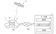
図2は、本実施形態に係る逆走検出装置を有する逆走検出システムの全体構成を示す図である。図2に示すように、逆走検出システムは、車両1に搭載された車載装置100と、ネットワーク200を介して車載装置100と通信可能なサーバ装置3とを有する。
FIG. 2 is a diagram showing the overall configuration of a reverse running detection system having a reverse running detecting device according to this embodiment. As shown in FIG. 2, the wrong-way detection system includes an on-
車載装置100は、測位衛星2から送信された測位用の信号を受信する測位センサ10と、ネットワーク200を介してサーバ装置3と通信する通信ユニット11とを有する。測位衛星2は、GPS衛星や準天頂衛星などの人工衛星であり、測位センサ10が受信した測位衛星2からの測位情報を利用して、車両1の現在位置(緯度、経度、高度)を算出することができる。なお、算出された現在位置は高精度であるとは限らず、測位センサ10からの信号のみで走行車線を精度よく特定すること、つまり逆走を検出することは困難な場合がある。
The in-
ネットワーク200には、インターネット網や携帯電話網等に代表される公衆無線通信網だけでなく、所定の管理地域ごとに設けられた閉鎖的な通信網、例えば無線LAN、Wi-Fi(登録商標)、Bluetooth(登録商標)等も含まれる。サーバ装置3は、例えば単一のサーバとして、あるいは機能ごとに別々のサーバから構成される分散サーバとして構成される。クラウドサーバと呼ばれるクラウド環境に作られた分散型の仮想サーバとしてサーバ装置3を構成することもできる。
The
サーバ装置3は、CPU,ROM,RAM、およびその他の周辺回路を有する演算処理装置を含んで構成され、機能的構成として、通信部31と、路面プロファイル生成部32と、記憶部33とを有する。
The
通信部31は、ネットワーク200を介し車載装置100と無線通信可能に構成され、車両1の位置情報と、車両1の走行情報とを、車両1の通信ユニット11を介してそれぞれ取得する。位置情報は、車両1の測位センサ10が受信した信号によって算出された車両1の現在位置を示す情報である。走行情報は、車両1に搭載された各種センサにより取得された車両1の走行状態を示す情報である。走行情報には、車両1の左右方向の加速度(横加速度)を検出する加速度センサ(横加速度センサ)による検出値の情報が含まれる。通信部31は、逆走を検出する対象となる車両(対象車両)1だけでなく、対象車両以外の複数の車両1の位置情報と走行情報とを常時取得する。
The
路面プロファイル生成部32は、通信部31を介して取得された対象車両以外の複数の車両1の位置情報と走行情報とに基づいて、路面性状を示す路面プロファイルを生成する。図3Aの特性f1は、路面プロファイルの一例を示す図である。図中の横軸は、車両1の正規の進行方向の位置、つまり図1のA1方向の道のりであり、縦軸は、路面の凹凸の量(深さまたは高さ)、つまり路面粗さである。
The road surface
一般に、路面の凹凸の量が大きいほど車両1の横加速度は大きい。したがって、路面性状と横加速度とは所定の相関関係を有する。路面プロファイル生成部32は、この所定の相関関係を用いて、横加速度から道路上の車両位置に対応する路面の凹凸量を算出し、図3Aに示すように車両1の進行方向における路面プロファイルを生成する。
Generally, the greater the amount of unevenness on the road surface, the greater the lateral acceleration of the
さらに、路面プロファイル生成部32は、路面プロファイルの特性f1を、図3Aに示すように所定距離毎に例えば1,2・・等の整数によって表されるデジタル値(整数値)に変換する。すなわち、凹凸量が大きいほど大きな値となるようなデジタル値に変換する。これにより、路面プロファイルがデジタル値の羅列によって表される。例えば図3Aの例では、「2→1→2→3→1→3→1」のデジタル値の羅列によって路面プロファイルが表される。
Furthermore, the road surface
同一車線を異なる車両1が走行する場合に、路面上のタイヤの位置が異なることにより、各車両1の横加速度センサにより検出された路面プロファイルが異なることがある。この場合、路面プロファイル生成部32は、例えば各車両1の横加速度センサにより検出されたそれぞれの路面プロファイルを平均化して、各路面の代表的な路面プロファイルを生成する。この場合もデジタル値の羅列によって路面プロファイルが表される。
When
路面プロファイル生成部32は、路面性状の測定用の専用車両を走行させることにより得られたデータから、路面プロファイルを生成することもできる。例えばレーザプロファイラを搭載した専用車両を走行させ、そのときの測定データを、専用車両の位置データとともに取得することで、横加速度センサを用いることなく路面プロファイルを生成することもできる。
The road surface
記憶部33は、路面プロファイル生成部32により路面プロファイルが生成されるときに用いられる路面性状と横加速度との間の所定の相関関係を記憶するとともに、道路地図情報を記憶する。道路地図情報には、道路の位置情報、道路形状(曲率など)の情報、道路の勾配の情報、交差点や分岐点の位置情報、車線数の情報、車線の幅員および車線毎の位置情報が含まれる。車線毎の位置情報とは、車線の中央位置や車線位置の境界の情報などである。さらに道路地図情報には、路面プロファイル生成部32により生成された道路の各位置での路面プロファイルの情報、すなわちデジタル値の羅列によって表される路面プロファイルの情報が含まれる。
The
記憶部33に記憶される道路地図情報のうち、路面プロファイルの情報は、路面プロファイル生成部32により路面プロファイルが生成される度に更新される。他の道路地図情報は、所定周期で、あるいは任意のタイミングで更新される。なお、本実施形態では、車両1の逆走を検出する場合、車両1の走行位置における路面プロファイル(参照用路面プロファイル)が既に記憶部33に記憶されているものとして扱う。
Among the road map information stored in the
図4は、本実施形態に係る逆走検出装置101の機能的構成を示すブロック図である。逆走検出装置101は、図1の車載装置100の一部を構成する。図4に示すように、逆走検出装置101は、測位センサ10と、通信ユニット11と、センサ群13と、報知部14と、コントローラ20とを備える。測位センサ10と通信ユニット11とセンサ群13と報知部14とは、それぞれコントローラ20に通信可能に接続される。
FIG. 4 is a block diagram showing the functional configuration of the reverse running
センサ群13は、車両1の走行状態を検出する複数のセンサの総称である。センサ群13には、車両1の左右方向の加速度を検出する横加速度センサ131が含まれる。報知部14は、車両1のドライバに所定情報を報知するための機器であり、画像表示用のモニタや音声出力用のスピーカにより構成される。
The
コントローラ20は、CPU等の演算部と、ROM,RAM等の記憶部と、その他の周辺回路とを有するコンピュータを含んで構成される電子制御ユニットである。コントローラ20の演算部は、機能的構成として、情報取得部21と、逆走判定部25と、出力部26とを有する。情報取得部21は、位置情報取得部211と、走行情報取得部212と、道路地図情報取得部213とを有する。コントローラ20の記憶部には、サーバ装置3の記憶部33と同様、路面プロファイルが生成されるときに用いられる路面性状と横加速度との間の所定の相関関係や、各種判定を行う場合の閾値などが記憶される。
The
位置情報取得部211は、測位センサ10により検出された車両1の現在の位置情報を取得する。走行情報取得部212は、センサ群13により検出された各種検出値を含む車両1の走行情報を取得する。道路地図情報取得部213は、通信ユニット11を介してサーバ装置3から道路地図情報を取得する。より詳しくは、道路地図情報取得部213は、測位センサ10により検出された車両1の現在位置における道路の車線情報と、各車線の路面プロファイルの情報とを含む道路地図情報を取得する。
The position
逆走判定部25は、位置情報取得部211により取得された車両1の現在の位置情報と、走行情報取得部212により取得された車両1の走行情報と、道路地図情報取得部213により取得された車両1の走行中の道路の道路地図情報とに基づいて、車両1が逆走しているか否かを判定する。すなわち、車両1が図1の車線R1を矢印A2方向に走行しているか否か、および図1の車線R2を矢印A1方向に走行しているか否かを判定する。
The wrong-way
この場合、まず、予め記憶された路面性状と横加速度との相関関係を用いて、横加速度センサ131により検出された横加速度から路面の凹凸量を算出する。なお、車両1が旋回走行中等で車両1に横加速度が生じている場合には、その影響を考慮して、すなわちその分を補正して、横加速度センサ131の検出値から路面の凹凸量を算出する。そして、車両1の進行方向に沿った路面の凹凸量の変化を表す路面プロファイル、すなわち実測路面プロファイルを生成する。次いで、生成された実測路面プロファイルを図3Aに示すように所定距離毎にデジタル値(整数値)に変換する。これにより、デジタル値の羅列、すなわち実測整数値の羅列によって実測路面プロファイルが表される。
In this case, first, the amount of unevenness of the road surface is calculated from the lateral acceleration detected by the
さらに、逆走判定部25は、測位センサ10からの信号に基づいて車両1の進行方向を判定する。すなわち、車両1の時系列の位置変化を検出することで、車両1の進行方向が図1の矢印A1方向(第1方向と呼ぶ)および矢印A2方向(第2方向と呼ぶ)のいずれであるかを判定する。車両1の進行方向が第1方向A1であると判定されると、道路地図情報に含まれる車両1の現在位置に対応する路面プロファイルのうち、第1方向A1が正規方向である第1車線R1の路面プロファイル(第1参照用路面プロファイルと呼ぶ)と、実測路面プロファイルとの類似性を示す一致度を算出する。そして、一致度が所定値以上であるとき、車両1が逆走ではない、すなわち車両1は第1車線R1を走行していると判定する。一致度の算出は、路面プロファイルを示すデジタル値同士を比較して行う。例えば、デジタル値の大きさを互いに比較し、その差の大小に応じて、またはデジタル値の変化率の違いに応じて、一致度を算出する。
Furthermore, the wrong-way
一方、一致度が所定値未満であるならば、車両1が逆走している可能性がある。この場合、逆走判定部25は、道路地図情報に含まれる車両1の現在位置に対応する路面プロファイルのうち、車両1の進行方向(第1方向A1)とは反対の第2方向A2が正規方向である第2車線R2の路面プロファイル(第2参照用路面プロファイルと呼ぶ)と、実測路面プロファイルとに基づいて車両1の逆走を判定する。
On the other hand, if the degree of coincidence is less than the predetermined value, there is a possibility that the
より詳しくは、まず、第2参照用路面プロファイルのデジタル値の羅列の順序を逆転させ、第2参照用路面プロファイルを逆走判定用の路面プロファイルに変換する。例えば第2参照用路面プロファイルのデジタル値の羅列が「2→1→2→3→1→3→1」(図3A)であるとき、第2方向A2の道のりに沿った変換後の路面プロファイルは、図3Bに示すように、「1→3→1→3→2→1→2」となる。次いで、この変換後の路面プロファイルのデジタル値の変化に着目し、デジタル値が増加したときにプラス+、デジタル値が減少したときにマイナス-、デジタル値が変化しないときに0または+として、デジタル値の変化を求める。図3Bの例では、デジタル値の変化は「(+)→(-)→(+)→(-)→(-)→(+)」となる。 More specifically, first, the order of the digital values of the second reference road surface profile is reversed, and the second reference road surface profile is converted into a road surface profile for wrong-way driving determination. For example, when the enumeration of digital values of the second reference road surface profile is "2 → 1 → 2 → 3 → 1 → 3 → 1" (FIG. 3A), the road surface profile after conversion along the road in the second direction A2 As shown in FIG. 3B, the order becomes "1→3→1→3→2→1→2". Next, we focused on the change in the digital value of the road surface profile after this conversion, and determined that when the digital value increases, it is positive +, when the digital value decreases, it is negative -, and when the digital value does not change, it is 0 or +. Find the change in value. In the example of FIG. 3B, the change in digital value is "(+)→(-)→(+)→(-)→(-)→(+)".
逆走判定部25は、このデジタル値の変化と、実測路面プロファイルから求められるデジタル値の変化とを比較し、路面プロファイルの一致度を算出する。そして、一致度が所定値以上であるとき、車両1が逆走であると判定する。このようにデジタル値の大きさではなく、デジタル値の変化(増減)、つまり路面の凹凸の連続性に基づいて逆走を判定することで、逆走の有無を容易かつ精度よく判定することができる。すなわち、デジタル値の大きさにはばらつき(誤差)が生じやすいが、デジタル値の増減の傾向にはばらつきが生じにくい。例えば、デジタル値の大きさを基準とする場合、路面の凹凸のピーク値を精度よく検出する必要があるが、デジタル値の変化を基準とする場合、ピーク値を精度よく検出する必要はなく、凹凸の傾向さえ検出できればよい。このため、デジタル値の変化に基づく逆走判定により、逆走を容易かつ精度よく判定することができる。
The wrong-way
出力部26は、逆走判定部25により車両1が逆走であると判定されると、報知部14に警報信号を出力する。これにより、車両1のモニタに警報メッセージが表示され、またはスピーカから警報音声が出力される。その結果、ドライバは車両1が逆走していることを認識することができる。出力部26は、通信ユニット11を介してサーバ装置3に警報信号を送信するともに、サーバ装置3が対象車両1の周囲の他の車両1に、または対象車両1から所定距離内の道路に面して設置された表示部に、警報信号を出力するようにしてもよい。これにより、他の車両1のドライバに注意喚起することができる。
The
図5は、予め定められたプログラムに従い図4のコントローラ20で実行される処理の一例を示すフローチャートである。このフローチャートに示す処理は、車両走行時に実行され、所定周期で繰り返される。まず、ステップS1で、測位センサ10により検出された車両1の現在の位置情報と、センサ群13により得られた車両1の走行情報と、通信ユニット11を介して得られた走行中の道路の道路地図情報とを取得する。
FIG. 5 is a flowchart showing an example of a process executed by the
次いで、ステップS2で、横加速度センサ131の検出値に基づいて実測路面プロファイルを算出する。算出された実測路面プロファイルは、図3Aに示すように、デジタル値(実測整数値)の羅列によって表される。次いで、ステップS3で、測位センサ10からの信号に基づいて車両1の移動方向が図1の第1方向A1であるか否かを判定する。
Next, in step S2, an actually measured road surface profile is calculated based on the detected value of the
ステップS3で肯定されるとステップS4に進み、ステップS2で算出された実測路面プロファイルと、車両1の現在位置に対応する第1参照用路面プロファイル、すなわち道路地図情報に含まれる第1車線R1の第1参照用路面プロファイルとの一致度が所定値以上であるか否かを判定する。具体的には、実測路面プロファイルを表すデジタル値と第1参照用路面プロファイルを表すデジタル値とを比較して一致度を算出する。なお、所定値は第1所定値であり、第1所定値は例えば50%~80%の範囲内の値に設定される。ステップS4で肯定されるとステップS5に進む。ステップS5では、車両1が第1車線R1に沿って第1方向A1に進行しているものと判断し、車両1の逆走なしと判定して処理を終了する。
If the answer is yes in step S3, the process proceeds to step S4, where the actual measured road surface profile calculated in step S2 and the first reference road surface profile corresponding to the current position of the
ステップS4で否定されるとステップS6に進み、車両1の現在位置に対応する第2参照用路面プロファイル、すなわち道路地図情報に含まれる第2車線R2の第2参照用路面プロファイルを表すデジタル値を、逆走判定用の値に変換する。より詳しくは、第2参照用路面プロファイルのデジタル値の羅列を逆転させるとともに、デジタル値の増減をプラス、マイナスの符号で表した符号の羅列である変換後の路面プロファイルを生成する。
If the result in step S4 is negative, the process proceeds to step S6, where a digital value representing the second reference road surface profile corresponding to the current position of the
次いで、ステップS7で、ステップS2で算出された実測路面プロファイルと、ステップS6で生成された路面プロファイルとの一致度が所定値以上であるか否かを判定する。すなわち、実測路面プロファイルを表すデジタル値の変化が、ステップS6のデジタル値の変化に所定の程度以上、一致しているか否かを判定する。なお、所定値は第2所定値であり、第2所定値は例えば50%~80%の範囲内の値に設定される。第2所定値をステップS4の第1所定値より大きい値に設定してもよく、第2所定値を第1所定値と等しい値、あるいは第1所定値より小さい値に設定してもよい。 Next, in step S7, it is determined whether the degree of coincidence between the measured road surface profile calculated in step S2 and the road surface profile generated in step S6 is greater than or equal to a predetermined value. That is, it is determined whether the change in the digital value representing the actually measured road surface profile matches the change in the digital value in step S6 to a predetermined degree or more. Note that the predetermined value is a second predetermined value, and the second predetermined value is set to a value within the range of 50% to 80%, for example. The second predetermined value may be set to a value larger than the first predetermined value in step S4, or the second predetermined value may be set to a value equal to the first predetermined value or a value smaller than the first predetermined value.
ステップS7で肯定されるとステップS8に進み、否定されると処理を終了する。ステップS8では、車両1が第2車線R2に沿って第1方向A1に進行しているものと判断する。すなわち、車両1の逆走ありと判定する。次いで、ステップS9で、報知部14に警報信号を出力し、車両1のモニタやスピーカから警報を発生させて処理を終了する。
If the answer in step S7 is affirmative, the process proceeds to step S8, and if the answer is negative, the process ends. In step S8, it is determined that the
一方、ステップS3で否定、すなわち車両1の移動方向が図1の第2方向A2であると判定されると、ステップS10に進む。ステップS10では、ステップS2で算出された実測路面プロファイルと、車両1の現在位置に対応する第2参照用路面プロファイル、すなわち道路地図情報に含まれる第2車線R2の第2参照用路面プロファイルとの一致度が所定値以上であるか否かを判定する。具体的には、ステップS4と同様、実測路面プロファイルを表すデジタル値と第2参照用路面プロファイルを表すデジタル値とを比較して一致度を算出する。なお、所定値はステップS4の第1所定値と等しい。
On the other hand, if the result in step S3 is negative, that is, if it is determined that the moving direction of the
ステップS10で肯定されるとステップS5に進み、否定されるとステップS11に進む。ステップS11では、車両1の現在位置に対応する第1参照用路面プロファイル、すなわち道路地図情報に含まれる第1車線R1の第1参照用路面プロファイルを表すデジタル値を、逆走判定用の値に変換する。より詳しくは、第1参照用路面プロファイルのデジタル値の羅列を逆転させるとともに、デジタル値の増減をプラス、マイナスの符号で表した符号の羅列である変換後の路面プロファイルを生成する。次いで、ステップS7に進む。
If the result of step S10 is affirmative, the process proceeds to step S5, and if the result is negative, the process proceeds to step S11. In step S11, a digital value representing the first reference road surface profile corresponding to the current position of the
本実施形態に係る逆走検出装置101による動作をまとめると以下のようになる。図6は、第1車線R1に沿って走行する車両1の状態をタイヤ1aによって模式的に示す図であり、路面形状は、第1参照用路面プロファイルのデジタル値によって表される。図6に示すように、車両1が第1方向A1に走行するとき、実測路面プロファイルと第1参照用路面プロファイルとが比較される(ステップS4)。そして、その一致度が所定値以上であるとき、逆走なしと判定される(ステップS5)。
The operation of the reverse running
一方、車両1が第2方向A2に進行するとき、実測路面プロファイルと第2参照用路面プロファイルの一致度が所定値以上であるか否かが判定される(ステップS10)。この場合、一致度が所定値以上ではないため、第1参照用路面プロファイルのデジタル値の羅列を逆転した変換後の第1参照用路面プロファイルの変化と実測路面プロファイルの変化とが比較される(ステップS11→ステップS7)。そして、その一致度が所定値以上であるとき、逆走ありと判定され、警報信号が出力される(ステップS8、ステップS9)。
On the other hand, when the
本実施形態によれば以下のような作用効果を奏することができる。
(1)逆走検出装置101は、車両1を測位する測位センサ10により得られた車両1の現在位置の位置情報を取得する位置情報取得部211と、車両1が走行する路面の路面プロファイルに応じて変化する横加速度センサ131のセンサ値の情報を含む車両1の走行情報を取得する走行情報取得部212と、道路の車線情報と路面プロファイルの情報とを含む道路地図情報を取得する道路地図情報取得部213と、位置情報取得部211により取得された位置情報と、走行情報取得部212により取得された走行情報と、道路地図情報取得部213により取得された道路地図情報とに基づいて、車両1の逆走を判定する逆走判定部25と、を備える(図4)。道路地図情報取得部213により取得された道路地図情報には、進行方向が第1方向A1に規定された第1車線R1の路面プロファイルである第1参照用路面プロファイルと、進行方向が第1方向A1の反対の第2方向A2に規定された第2車線R2の路面プロファイルである第2参照用路面プロファイルとが含まれる(図1)。逆走判定部25は、走行情報取得部212により取得された横加速度の情報に基づいて車両1が走行中の路面における実測路面プロファイルを求めるとともに、位置情報取得部211により取得された位置情報に基づいて車両1の進行方向を判定し、車両1の進行方向が第1方向A1であると判定されると、実測路面プロファイルと位置情報取得部211により取得された車両1の現在位置に対応する第1参照用路面プロファイルとの一致度が第1所定値以上であるか否かをさらに判定し、実測路面プロファイルと第1参照用路面プロファイルとの一致度が第1所定値未満と判定されると、実測路面プロファイルと位置情報取得部211により取得された車両1の現在位置に対応する第2参照用路面プロファイルとに基づいて、車両1の逆走を判定する(図5)。According to this embodiment, the following effects can be achieved.
(1) The reverse running
この構成により、車両自体で逆走の有無を判定することができる。このため、道路に逆走検出用のカメラを設置する必要がなく、車両1の逆走を全体として安価に検出することができる。また、路面プロファイルに基づいて車両1の逆走を検出するので、車線を精度よく検出する必要がなく、車両1の大まかな位置を検出できればよい。つまり、現在走行中の車線が第1車線R1と第2車線R2のいずれであるかを検出する必要はない。このため、高精度の測位センサ10が不要であり、この点でも装置を安価に構成できる。
With this configuration, the vehicle itself can determine whether or not the vehicle is driving in the wrong direction. Therefore, there is no need to install a camera for detecting wrong-way driving on the road, and it is possible to detect the wrong-way driving of the
(2)逆走判定部25は、実測路面プロファイルと第1参照用路面プロファイルとの一致度が第1所定値未満と判定されると、第2参照用路面プロファイルを逆走方向の参照用路面プロファイルに変換するとともに、変換後の参照用路面プロファイルと実測路面プロファイルとの一致度に基づいて、車両1の逆走を判定する(図5)。このように路面プロファイルに基づいて逆走を判定することで、逆走を精度よく判定することができる。すなわち、本実施形態では、正規方向と逆走方向とで路面プロファイルが互いに異なる点に着目し、各方向の路面プロファイルの一致度に基づいて逆走の有無を判定するので、低コストで車両1の逆走を精度よく検出することができる。
(2) When it is determined that the degree of coincidence between the measured road surface profile and the first reference road surface profile is less than the first predetermined value, the reverse driving
(3)逆走判定部25は、路面の凹凸量の大きさに基づいて第1参照用路面プロファイルと実測路面プロファイルとの一致度を算出するとともに、路面の凹凸量の変化に基づいて変換後の参照用路面プロファイルと実測路面プロファイルとの一致度を算出する。すなわち、正規方向の判定と逆走方向の判定とを互いに異なる方法で行う。これにより、車両1の逆走を効率的かつ精度よく検出することができる。
(3) The wrong-way
(4)逆走検出装置101は、逆走判定部25により車両1が逆走であると判定されると、警報信号を出力する出力部26をさらに備える(図4)。これにより、車両1が逆走であることをドライバ等に報知することができる。
(4) The wrong-way driving
(5)本実施形態の逆走検出装置101は、逆走検出方法として用いることもできる。逆走検出方法においては、車両1を測位する測位センサ10により得られた車両1の現在位置の位置情報と、車両1が走行する路面の路面プロファイルに応じて変化する横加速度センサ131のセンサ値の情報を含む車両1の走行情報と、道路の車線情報と路面プロファイルの情報とを含む道路地図情報と、をそれぞれ取得するステップ(ステップS1)と、取得された位置情報と走行情報と道路地図情報とに基づいて、車両1の逆走を判定するステップと、をコンピュータにより実行することを含む(図5)。取得された道路地図情報には、進行方向が第1方向A1に規定された第1車線R1の路面プロファイルである第1参照用路面プロファイルと、進行方向が第1方向A1の反対の第2方向A2に規定された第2車線R2の路面プロファイルである第2参照用路面プロファイルとが含まれる(図1)。車両1の逆走を判定するステップは、取得されたセンサ値の情報に基づいて車両1が走行中の路面における実測路面プロファイルを求めるとともに、取得された位置情報に基づいて車両1の進行方向を判定し(ステップS3)、車両1の進行方向が第1方向A1であると判定されると、実測路面プロファイルと取得された車両1の現在位置に対応する第1参照用路面プロファイルとの一致度が所定値以上であるか否かをさらに判定し(ステップS4)、実測路面プロファイルと第1参照用路面プロファイルとの一致度が所定値未満と判定されると、実測路面プロファイルと取得された車両1の現在位置に対応する第2参照用路面プロファイルとに基づいて、車両1の逆走を判定する(ステップS7、ステップS8)。これにより、安価な構成で車両1の逆走を検出することができる。
(5) The reverse running
なお、上記実施形態では、走行情報取得部212が横加速度センサ131の検出値(センサ値)の情報を含む車両1の走行情報を取得するようにしたが、路面プロファイルに応じて変化する他の検出器の検出値の情報を含む走行情報を取得するようにしてもよい。例えば車両1の前後方向の加速度(前後加速度)を検出するセンサの検出値や、ロール角やロールレートを検出するセンサの検出値、さらに上下方向の車両の振動を検出するセンサの検出値の情報を含む走行情報を、走行情報取得部が取得するようにしてもよい。
Note that in the above embodiment, the driving
上記実施形態では、車両1が正規方向に走行しているか否かを、路面プロファイルを表すデジタル値(整数)の大きさに基づいて判定し、車両1が逆走方向に走行しているか否かを、路面プロファイルを表すデジタル値(整数)の変化に基づいて判定するようにしたが、これらの判定手法は上述したものに限らない。例えば、車両1が正規方向に走行しているか否かを、路面プロファイルを表すデジタル値の変化に基づいて判定するようにしてもよく、車両1が逆走方向に走行しているか否かを、路面プロファイルを表すデジタル値の大きさに基づいて判定するようにしてもよい。
In the above embodiment, whether the
上記実施形態では、逆走検出装置101を車両1に搭載したが、逆走検出装置101の機能の一部または全部をサーバ装置3に設けるようにしてもよい。
In the embodiment described above, the wrong-way driving
上記実施形態では、測位衛星2から送信された測位用の信号を受信する測位センサ10を車両1に搭載したが、測位センサ10は、他の方法、例えば自立航法により車両位置を測位するものであってもよい。すなわち、測位センサは、測位衛星から送信された信号を受信して車両を測位するものに限らない。
In the above embodiment, the
以上の説明はあくまで一例であり、本発明の特徴を損なわない限り、上述した実施形態および変形例により本発明が限定されるものではない。上記実施形態と変形例の1つまたは複数を任意に組み合わせることも可能であり、変形例同士を組み合わせることも可能である。 The above description is merely an example, and the present invention is not limited to the above-described embodiments and modifications as long as the characteristics of the present invention are not impaired. It is also possible to arbitrarily combine the above embodiment and one or more of the modifications, and it is also possible to combine the modifications.
1 車両、2 測位衛星、10 測位センサ、11 通信ユニット、14 報知部、20 コントローラ、21 情報取得部、25 逆走判定部、26 出力部、101 逆走検出装置、131 横加速度センサ、211 位置情報取得部、212 走行情報取得部、213 道路地図情報取得部、R1 第1車線、R2 第2車線、A1 第1方向、A2 第2方向 1 vehicle, 2 positioning satellite, 10 positioning sensor, 11 communication unit, 14 notification section, 20 controller, 21 information acquisition section, 25 reverse running determination section, 26 output section, 101 reverse running detection device, 131 lateral acceleration sensor, 211 position Information acquisition unit, 212 Traveling information acquisition unit, 213 Road map information acquisition unit, R1 first lane, R2 second lane, A1 first direction, A2 second direction
Claims (6)
前記車両が走行する路面の路面プロファイルに応じて変化する検出器の検出値の情報を含む前記車両の走行情報を取得する走行情報取得部と、
道路の車線情報と前記路面プロファイルの情報とを含む道路地図情報を取得する道路地図情報取得部と、
前記位置情報取得部により取得された位置情報と、前記走行情報取得部により取得された走行情報と、前記道路地図情報取得部により取得された道路地図情報とに基づいて、前記車両の逆走を判定する逆走判定部と、を備え、
前記道路地図情報取得部により取得された道路地図情報には、進行方向が第1方向に規定された第1車線の路面プロファイルであり、路面の凹凸の程度を表す第1参照用路面プロファイルと、進行方向が前記第1方向の反対の第2方向に規定された第2車線の路面プロファイルであり、路面の凹凸の程度を表す第2参照用路面プロファイルとが含まれ、
前記逆走判定部は、
前記走行情報取得部により取得された前記検出値の情報に基づいて前記車両が走行中の路面の凹凸の程度を表す実測路面プロファイルを求めるとともに、前記位置情報取得部により取得された位置情報に基づいて前記車両の進行方向を判定し、
前記車両の進行方向が前記第1方向であると判定されると、前記実測路面プロファイルと前記位置情報取得部により取得された前記車両の現在位置に対応する前記第1参照用路面プロファイルとの一致度が所定値以上であるか否かをさらに判定し、
前記実測路面プロファイルと前記第1参照用路面プロファイルとの一致度が前記所定値未満と判定されると、前記実測路面プロファイルと前記位置情報取得部により取得された前記車両の現在位置に対応する前記第2参照用路面プロファイルとに基づいて、前記車両の逆走を判定することを特徴とする逆走検出装置。 a position information acquisition unit that acquires position information of the current position of the vehicle obtained by a positioning sensor that positions the vehicle;
a driving information acquisition unit that acquires driving information of the vehicle including information on a detection value of a detector that changes according to a road surface profile of a road surface on which the vehicle runs;
a road map information acquisition unit that acquires road map information including road lane information and information on the road surface profile;
Based on the position information acquired by the position information acquisition section, the travel information acquired by the travel information acquisition section, and the road map information acquired by the road map information acquisition section, the vehicle is driven in the wrong direction. A reverse running determination unit that determines,
The road map information acquired by the road map information acquisition unit includes a road surface profile of a first lane whose traveling direction is defined as a first direction, and a first reference road surface profile representing the degree of unevenness of the road surface. , a road surface profile of a second lane whose traveling direction is defined in a second direction opposite to the first direction, and a second reference road surface profile representing the degree of unevenness of the road surface ;
The reverse running determination unit includes:
Determining an actual road surface profile representing the degree of unevenness of the road surface on which the vehicle is traveling based on information on the detected values acquired by the driving information acquisition section, and based on the position information acquired by the position information acquisition section. determine the traveling direction of the vehicle,
When it is determined that the traveling direction of the vehicle is the first direction, the measured road surface profile matches the first reference road surface profile corresponding to the current position of the vehicle acquired by the position information acquisition unit. further determining whether the degree is greater than or equal to a predetermined value;
If it is determined that the degree of coincidence between the actually measured road surface profile and the first reference road surface profile is less than the predetermined value, then A wrong-way driving detection device that determines whether the vehicle is traveling in the wrong direction based on a second reference road surface profile.
前記逆走判定部は、前記実測路面プロファイルと前記第1参照用路面プロファイルとの一致度が前記所定値未満と判定されると、前記第2参照用路面プロファイルを逆走方向の参照用路面プロファイルに変換するとともに、変換後の参照用路面プロファイルと前記実測路面プロファイルとの一致度に基づいて、前記車両の逆走を判定することを特徴とする逆走検出装置。 The reverse running detection device according to claim 1,
When it is determined that the degree of coincidence between the actually measured road surface profile and the first reference road surface profile is less than the predetermined value, the reverse driving determining section converts the second reference road surface profile into a reference road surface profile in the reverse driving direction. What is claimed is: 1. A wrong-way driving detection device that determines whether the vehicle is traveling in the wrong direction based on a degree of coincidence between a reference road surface profile after the conversion and the actually measured road surface profile.
前記逆走判定部は、路面の凹凸量の大きさに基づいて前記第1参照用路面プロファイルと前記実測路面プロファイルとの一致度を算出するとともに、路面の凹凸量の変化に基づいて前記変換後の参照用路面プロファイルと前記実測路面プロファイルとの一致度を算出することを特徴とする逆走検出装置。 In the reverse running detection device according to claim 2,
The reverse driving determining unit calculates the degree of coincidence between the first reference road surface profile and the measured road surface profile based on the amount of unevenness of the road surface, and calculates the degree of coincidence between the first reference road surface profile and the measured road surface profile after the conversion based on the change in the amount of unevenness of the road surface. A wrong-way driving detection device that calculates a degree of coincidence between a reference road surface profile and the actually measured road surface profile.
前記逆走判定部により前記車両が逆走であると判定されると、警報信号を出力する出力部をさらに備えることを特徴とする逆走検出装置。 In the reverse running detection device according to any one of claims 1 to 3,
The wrong-way driving detection device further comprises an output section that outputs an alarm signal when the wrong-way driving determining section determines that the vehicle is traveling in the wrong direction.
前記第1参照用路面プロファイルは、前記第1方向に沿った所定距離毎の前記第1車線の路面の凹凸の程度を表す整数値の羅列によって表され、
前記第2参照用路面プロファイルは、前記第2方向に沿った前記所定距離毎の前記第2車線の路面の凹凸の程度を表す整数値の羅列によって表され、
前記逆走判定部は、前記実測路面プロファイルを、前記車両の進行方向に沿った前記所定距離毎の路面の凹凸の程度を表す実測整数値に変換し、前記実測整数値の羅列と、前記第1参照用路面プロファイルを表す前記整数値の羅列および前記第2参照用路面プロファイルを表す前記整数値の羅列とに基づいて、前記車両の逆走を判定することを特徴とする逆走検出装置。 In the reverse running detection device according to any one of claims 1 to 4,
The first reference road surface profile is represented by an enumeration of integer values representing the degree of unevenness of the road surface of the first lane for each predetermined distance along the first direction,
The second reference road surface profile is represented by an enumeration of integer values representing the degree of unevenness of the road surface of the second lane at each predetermined distance along the second direction,
The wrong-way driving determining unit converts the measured road surface profile into a measured integer value representing the degree of unevenness of the road surface at each predetermined distance along the traveling direction of the vehicle, and converts the measured road surface profile into a measured integer value representing the degree of unevenness of the road surface at each predetermined distance along the traveling direction of the vehicle, and A wrong-way driving detection device that determines whether the vehicle is traveling in the wrong direction based on the list of integer values representing the first reference road surface profile and the list of integer values representing the second reference road surface profile.
前記車両が走行する路面の路面プロファイルに応じて変化する検出器の検出値の情報を含む前記車両の走行情報を取得するステップと、
道路の車線情報と前記路面プロファイルの情報とを含む道路地図情報を取得するステップと、
取得された位置情報と走行情報と道路地図情報とに基づいて、前記車両の逆走を判定するステップと、をコンピュータにより実行することを含み、
取得された道路地図情報には、進行方向が第1方向に規定された第1車線の路面プロファイルであり、路面の凹凸の程度を表す第1参照用路面プロファイルと、進行方向が前記第1方向の反対の第2方向に規定された第2車線の路面プロファイルであり、路面の凹凸の程度を表す第2参照用路面プロファイルとが含まれ、
前記車両の逆走を判定するステップは、
取得された前記検出値の情報に基づいて前記車両が走行中の路面の凹凸の程度を表す実測路面プロファイルを求めるとともに、取得された位置情報に基づいて前記車両の進行方向を判定し、
前記車両の進行方向が前記第1方向であると判定されると、前記実測路面プロファイルと取得された前記車両の現在位置に対応する前記第1参照用路面プロファイルとの一致度が所定値以上であるか否かをさらに判定し、
前記実測路面プロファイルと前記第1参照用路面プロファイルとの一致度が前記所定値未満と判定されると、前記実測路面プロファイルと取得された前記車両の現在位置に対応する前記第2参照用路面プロファイルとに基づいて、前記車両の逆走を判定することを含むことを特徴とする逆走検出方法。 acquiring position information of the current position of the vehicle obtained by a positioning sensor that positions the vehicle;
acquiring driving information of the vehicle including information on a detection value of a detector that changes depending on a road surface profile of a road surface on which the vehicle travels;
obtaining road map information including road lane information and information on the road surface profile;
a step of determining whether the vehicle is driving in the wrong direction based on the acquired position information, driving information, and road map information,
The acquired road map information includes a first reference road surface profile that is a road surface profile of a first lane whose traveling direction is defined as a first direction and represents the degree of unevenness of the road surface, and a first reference road surface profile whose traveling direction is defined as the first direction. is a road surface profile of a second lane defined in a second direction opposite to the direction, and includes a second reference road surface profile representing the degree of unevenness of the road surface ;
The step of determining whether the vehicle is driving in the wrong direction includes:
Determining a measured road surface profile representing the degree of unevenness of the road surface on which the vehicle is traveling based on the acquired detection value information, and determining the traveling direction of the vehicle based on the acquired position information;
When it is determined that the traveling direction of the vehicle is the first direction, the degree of coincidence between the actually measured road surface profile and the first reference road surface profile corresponding to the acquired current position of the vehicle is equal to or greater than a predetermined value. Further determine whether there is
When it is determined that the degree of coincidence between the measured road surface profile and the first reference road surface profile is less than the predetermined value, the second reference road surface profile corresponding to the measured road surface profile and the acquired current position of the vehicle is determined. A wrong-way driving detection method, comprising determining whether the vehicle is traveling in the wrong direction based on the following.
Applications Claiming Priority (3)
| Application Number | Priority Date | Filing Date | Title |
|---|---|---|---|
| JP2020083544 | 2020-05-12 | ||
| JP2020083544 | 2020-05-12 | ||
| PCT/JP2021/016983 WO2021230087A1 (en) | 2020-05-12 | 2021-04-28 | Wrong-way driving detecting device, and wrong-way driving detecting method |
Publications (2)
| Publication Number | Publication Date |
|---|---|
| JPWO2021230087A1 JPWO2021230087A1 (en) | 2021-11-18 |
| JP7402323B2 true JP7402323B2 (en) | 2023-12-20 |
Family
ID=78525700
Family Applications (1)
| Application Number | Title | Priority Date | Filing Date |
|---|---|---|---|
| JP2022521830A Active JP7402323B2 (en) | 2020-05-12 | 2021-04-28 | Reverse running detection device and reverse running detection method |
Country Status (3)
| Country | Link |
|---|---|
| US (1) | US20230211792A1 (en) |
| JP (1) | JP7402323B2 (en) |
| WO (1) | WO2021230087A1 (en) |
Citations (7)
| Publication number | Priority date | Publication date | Assignee | Title |
|---|---|---|---|---|
| JP2000235414A (en) | 1999-02-16 | 2000-08-29 | Toyota Motor Corp | Automatic traveling system |
| JP2004234486A (en) | 2003-01-31 | 2004-08-19 | Matsushita Electric Ind Co Ltd | Vehicle backward traveling detector |
| JP2009286172A (en) | 2008-05-27 | 2009-12-10 | Toyota Motor Corp | Vehicle controller and vehicle control method |
| JP2015524364A (en) | 2012-07-06 | 2015-08-24 | ジェイテクト ユーロップ | Method for detecting the direction of travel of an automobile |
| US20180365989A1 (en) | 2017-06-20 | 2018-12-20 | GM Global Technology Operations LLC | System and method for wrong-way driving detection and mitigation |
| JP2019095852A (en) | 2017-11-17 | 2019-06-20 | アイシン・エィ・ダブリュ株式会社 | Reverse run warning system, reverse run warning method, and reverse run warning program |
| JP2020015443A (en) | 2018-07-26 | 2020-01-30 | 日産自動車株式会社 | Vehicle control method and vehicle control device |
-
2021
- 2021-04-28 US US17/923,911 patent/US20230211792A1/en active Pending
- 2021-04-28 WO PCT/JP2021/016983 patent/WO2021230087A1/en active Application Filing
- 2021-04-28 JP JP2022521830A patent/JP7402323B2/en active Active
Patent Citations (7)
| Publication number | Priority date | Publication date | Assignee | Title |
|---|---|---|---|---|
| JP2000235414A (en) | 1999-02-16 | 2000-08-29 | Toyota Motor Corp | Automatic traveling system |
| JP2004234486A (en) | 2003-01-31 | 2004-08-19 | Matsushita Electric Ind Co Ltd | Vehicle backward traveling detector |
| JP2009286172A (en) | 2008-05-27 | 2009-12-10 | Toyota Motor Corp | Vehicle controller and vehicle control method |
| JP2015524364A (en) | 2012-07-06 | 2015-08-24 | ジェイテクト ユーロップ | Method for detecting the direction of travel of an automobile |
| US20180365989A1 (en) | 2017-06-20 | 2018-12-20 | GM Global Technology Operations LLC | System and method for wrong-way driving detection and mitigation |
| JP2019095852A (en) | 2017-11-17 | 2019-06-20 | アイシン・エィ・ダブリュ株式会社 | Reverse run warning system, reverse run warning method, and reverse run warning program |
| JP2020015443A (en) | 2018-07-26 | 2020-01-30 | 日産自動車株式会社 | Vehicle control method and vehicle control device |
Also Published As
| Publication number | Publication date |
|---|---|
| WO2021230087A1 (en) | 2021-11-18 |
| JPWO2021230087A1 (en) | 2021-11-18 |
| US20230211792A1 (en) | 2023-07-06 |
Similar Documents
| Publication | Publication Date | Title |
|---|---|---|
| US20170089717A1 (en) | Use of road lane data to improve traffic probe accuracy | |
| JP5015849B2 (en) | Reverse running warning device, reverse running warning method | |
| US8618923B2 (en) | Speed alarm system | |
| US10239525B2 (en) | Driving support information generation device, driving support information generation method, driving support device, and driving support method | |
| JP2014109795A (en) | Vehicle position estimation device | |
| WO2017187884A1 (en) | Recommended traveling speed provision program, travel assistance system, vehicle control device, and automatic traveling vehicle | |
| CN111009146B (en) | Server, information processing method, and non-transitory storage medium storing program | |
| JP7059817B2 (en) | Driving support device | |
| CN113508277A (en) | Lane marker location and fusion | |
| JP6005475B2 (en) | In-vehicle device, danger prediction method, and program | |
| JP6834914B2 (en) | Object recognition device | |
| KR101544854B1 (en) | Method for providing real time traffic information around vehicle and traffic information system using the same | |
| KR20130003521A (en) | Driving guidance system using sensors | |
| JP6790951B2 (en) | Map information learning method and map information learning device | |
| JP7402323B2 (en) | Reverse running detection device and reverse running detection method | |
| KR101977493B1 (en) | Apparatus and method for measuring distance between vehicles | |
| KR20210029323A (en) | Apparatus and method for improving cognitive performance of sensor fusion using precise map | |
| WO2021235209A1 (en) | Traffic lane estimation device and traffic lane estimation method | |
| JP2018085133A (en) | Determination device, receiving device, control method, program, and storage medium | |
| KR20150006983A (en) | Forward vehicle collision warning apparatus and method thereof | |
| JP7358053B2 (en) | Violation detection device and violation detection method | |
| JP2008196907A (en) | Distance conversion information creating system, on-board equipment and distance conversion information creating method | |
| JP2022174927A (en) | Acceleration sensor correction device, road gradient detector, and operation recorder | |
| JP2022056153A (en) | Temporary stop detection device, temporary stop detection system, and temporary stop detection program | |
| JP2011095960A (en) | Reverse travel alarm device |
Legal Events
| Date | Code | Title | Description |
|---|---|---|---|
| A621 | Written request for application examination |
Free format text: JAPANESE INTERMEDIATE CODE: A621 Effective date: 20221102 |
|
| A131 | Notification of reasons for refusal |
Free format text: JAPANESE INTERMEDIATE CODE: A131 Effective date: 20230704 |
|
| A521 | Request for written amendment filed |
Free format text: JAPANESE INTERMEDIATE CODE: A523 Effective date: 20230809 |
|
| TRDD | Decision of grant or rejection written | ||
| A01 | Written decision to grant a patent or to grant a registration (utility model) |
Free format text: JAPANESE INTERMEDIATE CODE: A01 Effective date: 20231114 |
|
| A61 | First payment of annual fees (during grant procedure) |
Free format text: JAPANESE INTERMEDIATE CODE: A61 Effective date: 20231208 |
|
| R150 | Certificate of patent or registration of utility model |
Ref document number: 7402323 Country of ref document: JP Free format text: JAPANESE INTERMEDIATE CODE: R150 |