WO2021230073A1 - 情報処理装置、情報処理方法、及び表示装置 - Google Patents
情報処理装置、情報処理方法、及び表示装置 Download PDFInfo
- Publication number
- WO2021230073A1 WO2021230073A1 PCT/JP2021/016797 JP2021016797W WO2021230073A1 WO 2021230073 A1 WO2021230073 A1 WO 2021230073A1 JP 2021016797 W JP2021016797 W JP 2021016797W WO 2021230073 A1 WO2021230073 A1 WO 2021230073A1
- Authority
- WO
- WIPO (PCT)
- Prior art keywords
- virtual camera
- information processing
- performer
- shooting
- target object
- Prior art date
Links
- 230000010365 information processing Effects 0.000 title claims abstract description 85
- 238000003672 processing method Methods 0.000 title claims description 8
- 238000012545 processing Methods 0.000 claims abstract description 31
- 238000000034 method Methods 0.000 claims description 101
- 230000033001 locomotion Effects 0.000 claims description 54
- 238000003384 imaging method Methods 0.000 claims description 8
- 230000001934 delay Effects 0.000 claims description 3
- 238000005516 engineering process Methods 0.000 abstract description 17
- 238000009826 distribution Methods 0.000 description 46
- 238000010586 diagram Methods 0.000 description 26
- 238000012544 monitoring process Methods 0.000 description 19
- 238000003860 storage Methods 0.000 description 16
- 230000005540 biological transmission Effects 0.000 description 15
- 210000000988 bone and bone Anatomy 0.000 description 12
- 238000007405 data analysis Methods 0.000 description 8
- 238000004364 calculation method Methods 0.000 description 7
- 238000004891 communication Methods 0.000 description 7
- 238000001514 detection method Methods 0.000 description 7
- 230000006399 behavior Effects 0.000 description 6
- 230000006870 function Effects 0.000 description 6
- 238000013459 approach Methods 0.000 description 5
- 230000001360 synchronised effect Effects 0.000 description 5
- 239000003550 marker Substances 0.000 description 4
- 238000013461 design Methods 0.000 description 3
- 230000000149 penetrating effect Effects 0.000 description 3
- 230000000007 visual effect Effects 0.000 description 3
- 210000004247 hand Anatomy 0.000 description 2
- 238000004519 manufacturing process Methods 0.000 description 2
- 210000000707 wrist Anatomy 0.000 description 2
- 230000001133 acceleration Effects 0.000 description 1
- 238000006243 chemical reaction Methods 0.000 description 1
- 230000006835 compression Effects 0.000 description 1
- 238000007906 compression Methods 0.000 description 1
- 230000003247 decreasing effect Effects 0.000 description 1
- 230000000694 effects Effects 0.000 description 1
- 230000008921 facial expression Effects 0.000 description 1
- 239000011521 glass Substances 0.000 description 1
- 230000005484 gravity Effects 0.000 description 1
- 238000007654 immersion Methods 0.000 description 1
- 230000002452 interceptive effect Effects 0.000 description 1
- JEIPFZHSYJVQDO-UHFFFAOYSA-N iron(III) oxide Inorganic materials O=[Fe]O[Fe]=O JEIPFZHSYJVQDO-UHFFFAOYSA-N 0.000 description 1
- 239000004973 liquid crystal related substance Substances 0.000 description 1
- 238000010801 machine learning Methods 0.000 description 1
- 230000003287 optical effect Effects 0.000 description 1
- 230000001151 other effect Effects 0.000 description 1
- 230000035515 penetration Effects 0.000 description 1
- 239000007787 solid Substances 0.000 description 1
Images


Classifications
-
- G—PHYSICS
- G06—COMPUTING; CALCULATING OR COUNTING
- G06T—IMAGE DATA PROCESSING OR GENERATION, IN GENERAL
- G06T17/00—Three dimensional [3D] modelling, e.g. data description of 3D objects
-
- G—PHYSICS
- G06—COMPUTING; CALCULATING OR COUNTING
- G06T—IMAGE DATA PROCESSING OR GENERATION, IN GENERAL
- G06T19/00—Manipulating 3D models or images for computer graphics
- G06T19/003—Navigation within 3D models or images
-
- G—PHYSICS
- G06—COMPUTING; CALCULATING OR COUNTING
- G06F—ELECTRIC DIGITAL DATA PROCESSING
- G06F3/00—Input arrangements for transferring data to be processed into a form capable of being handled by the computer; Output arrangements for transferring data from processing unit to output unit, e.g. interface arrangements
- G06F3/14—Digital output to display device ; Cooperation and interconnection of the display device with other functional units
-
- G—PHYSICS
- G06—COMPUTING; CALCULATING OR COUNTING
- G06T—IMAGE DATA PROCESSING OR GENERATION, IN GENERAL
- G06T7/00—Image analysis
- G06T7/20—Analysis of motion
-
- G—PHYSICS
- G06—COMPUTING; CALCULATING OR COUNTING
- G06V—IMAGE OR VIDEO RECOGNITION OR UNDERSTANDING
- G06V10/00—Arrangements for image or video recognition or understanding
- G06V10/70—Arrangements for image or video recognition or understanding using pattern recognition or machine learning
- G06V10/74—Image or video pattern matching; Proximity measures in feature spaces
- G06V10/761—Proximity, similarity or dissimilarity measures
-
- H—ELECTRICITY
- H04—ELECTRIC COMMUNICATION TECHNIQUE
- H04N—PICTORIAL COMMUNICATION, e.g. TELEVISION
- H04N21/00—Selective content distribution, e.g. interactive television or video on demand [VOD]
- H04N21/20—Servers specifically adapted for the distribution of content, e.g. VOD servers; Operations thereof
- H04N21/21—Server components or server architectures
- H04N21/218—Source of audio or video content, e.g. local disk arrays
- H04N21/21805—Source of audio or video content, e.g. local disk arrays enabling multiple viewpoints, e.g. using a plurality of cameras
-
- H—ELECTRICITY
- H04—ELECTRIC COMMUNICATION TECHNIQUE
- H04N—PICTORIAL COMMUNICATION, e.g. TELEVISION
- H04N21/00—Selective content distribution, e.g. interactive television or video on demand [VOD]
- H04N21/20—Servers specifically adapted for the distribution of content, e.g. VOD servers; Operations thereof
- H04N21/21—Server components or server architectures
- H04N21/218—Source of audio or video content, e.g. local disk arrays
- H04N21/2187—Live feed
-
- H—ELECTRICITY
- H04—ELECTRIC COMMUNICATION TECHNIQUE
- H04N—PICTORIAL COMMUNICATION, e.g. TELEVISION
- H04N21/00—Selective content distribution, e.g. interactive television or video on demand [VOD]
- H04N21/60—Network structure or processes for video distribution between server and client or between remote clients; Control signalling between clients, server and network components; Transmission of management data between server and client, e.g. sending from server to client commands for recording incoming content stream; Communication details between server and client
- H04N21/65—Transmission of management data between client and server
- H04N21/658—Transmission by the client directed to the server
- H04N21/6587—Control parameters, e.g. trick play commands, viewpoint selection
-
- H—ELECTRICITY
- H04—ELECTRIC COMMUNICATION TECHNIQUE
- H04N—PICTORIAL COMMUNICATION, e.g. TELEVISION
- H04N21/00—Selective content distribution, e.g. interactive television or video on demand [VOD]
- H04N21/80—Generation or processing of content or additional data by content creator independently of the distribution process; Content per se
- H04N21/81—Monomedia components thereof
- H04N21/816—Monomedia components thereof involving special video data, e.g 3D video
-
- G—PHYSICS
- G06—COMPUTING; CALCULATING OR COUNTING
- G06T—IMAGE DATA PROCESSING OR GENERATION, IN GENERAL
- G06T2210/00—Indexing scheme for image generation or computer graphics
- G06T2210/21—Collision detection, intersection
Definitions
- This technology relates to an information processing device, an information processing method, and a display device applicable to image display in virtual space.
- Patent Document 1 describes a content distribution server that distributes live content using virtual characters.
- a virtual character that operates according to the movement of the distributor is arranged in the virtual space, and an image in the virtual space is shot from the viewpoint of the virtual camera.
- the shooting position of the virtual camera and the like are controlled according to the instructions of the viewers participating as cameramen.
- the video captured by the virtual camera is distributed to the viewer terminal as live content (paragraphs [0018] [0038] [0045] FIG. 1 of Patent Document 1 and the like).
- Technology for distributing live content using virtual space is expected to be applied in various fields such as entertainment and education, and technology for properly shooting an object in virtual space is required.
- an object of the present technology is to provide an information processing device, an information processing method, and a display device capable of appropriately photographing an object in a virtual space.
- the information processing apparatus includes a shooting control unit.
- the shooting control unit is for avoiding a collision of the virtual camera with the target object according to the positional relationship between the target object operating in the virtual space and the virtual camera that moves in the virtual space and shoots the target object. Execute collision avoidance processing
- collision avoidance processing is executed according to the positional relationship between the target object in the virtual space and the virtual camera that shoots the target object while moving in the virtual space. As a result, the collision between the target object and the virtual camera is avoided in advance, and the target can be properly photographed in the virtual space.
- the shooting control unit detects a close state between the target object and the virtual camera based on the positional relationship between the target object and the virtual camera, and when the close state is detected, the collision avoidance process. May be executed.
- the shooting control unit may detect a state in which the relative distance between the target object and the virtual camera is equal to or less than a predetermined threshold value as the proximity state.
- the relative distance may include a current value or a predicted value.
- the virtual camera may shoot the target object along a preset shooting path.
- the imaging control unit may change the imaging path as the collision avoidance process when the proximity state is detected.
- the shooting route may be a route set so that the virtual camera passes through a plurality of relay points in order.
- the shooting control unit may change the relay point that is the movement target of the virtual camera so that the collision between the target object and the virtual camera is avoided when the proximity state is detected.
- the shooting control unit may set the movement target of the virtual camera to the relay point having the closest order so as to avoid a collision between the target object and the virtual camera.
- the photographing control unit is at least a part of the route to the relay point which is the movement target of the virtual camera so that the collision between the target object and the virtual camera is avoided when the proximity state is detected. May be changed.
- the shooting control unit may move the virtual camera along a detour route that bypasses the target object from the point where the proximity state is detected.
- the detour route may be a route that keeps the relative distance between the target object and the virtual camera constant.
- the shooting route may be a route in which the passing time of the virtual camera is set for each of the plurality of relay points.
- the shooting control unit may adjust the moving speed of the virtual camera moving on the changed shooting path based on the passing time set at the relay point.
- the plurality of relay points may include at least one important relay point.
- the imaging control unit may adjust the moving speed of the virtual camera according to the passing time of the important relay point included in the imaging path after the change.
- the shooting control unit When the proximity state is detected, the shooting control unit performs a display image for displaying the target object from an image taken by the virtual camera to an image taken by another virtual camera as the collision avoidance process. You may switch to.
- the shooting control unit may move the virtual camera so that the relative distance between the target object and the virtual camera becomes constant as the collision avoidance process.
- the shooting control unit may delay the timing of the speed change of the virtual camera with respect to the timing of the speed change of the target object so that the relative distance falls within a predetermined range.
- the target object may include a three-dimensional live-action model of the performer.
- the shooting control unit may deliver the image taken by the virtual camera in real time.
- the information processing method is an information processing method executed by a computer system, in which a target object operating in a virtual space and a virtual camera that moves in the virtual space and shoots the target object are used. It includes executing a collision avoidance process for avoiding a collision of the virtual camera with the target object according to the positional relationship.
- the display device includes an image acquisition unit and a display unit.
- the image acquisition unit causes the virtual camera to collide with the target object, which is executed according to the positional relationship between the target object operating in the virtual space and the virtual camera that moves in the virtual space and shoots the target object.
- An image taken by the virtual camera that operates according to a collision avoidance process for avoidance is acquired.
- the display unit displays an image taken by the virtual camera.
- FIG. It is a schematic diagram which shows an example of the collision avoidance processing which changes a shooting path. It is a flowchart of the collision avoidance processing shown in FIG. It is a schematic diagram which shows another example of the collision avoidance processing which changes a shooting path. It is a flowchart of the collision avoidance processing shown in FIG. It is a schematic diagram which shows another example of the collision avoidance processing of a virtual camera. It is a flowchart of the collision avoidance processing shown in FIG. It is a schematic diagram which shows the example of a collision between a shooting target and a virtual camera.
- FIG. 1 is a schematic diagram showing a configuration example of a distribution system according to an embodiment of the present technology.
- the distribution system 100 is a system that distributes live contents using a virtual space in real time.
- the distribution system 100 includes a distribution server 10, a shooting system 11, and at least one client terminal 12.
- the distribution server 10 and each client terminal 12 are connected to each other so as to be able to communicate with each other via the Internet 13.
- the distribution server 10 and each client terminal 12 may be connected via a dedicated network line such as a private network.
- an outline of the distribution system 100 will be described by taking as an example a case where a live music or the like is performed in a virtual space.
- the distribution server 10 generates live content using the virtual space, and distributes the generated live content to each client terminal 12 via the Internet 13. That is, the distribution server 10 provides a live content distribution service.
- a virtual model operated by the performer 1 who plays the leading role of the live content a stage set, a background, and other CG (Computer Graphics) objects are arranged.
- the performer 1 can perform various performances such as singing, dancing, and playing a musical instrument in the virtual space.
- the distribution server 10 constitutes such a virtual space, and obtains images taken of the virtual space, audio of the virtual space, data related to virtual objects (virtual model of performer 1 and other objects, etc.) arranged in the virtual space, and the like. , Generate as live content.
- the image includes a still image and a moving image. In the following, moving images (videos) of virtual spaces are mainly used as live contents.
- the photographing system 11 is a system that photographs and senses the performer 1 and generates data necessary for generating a virtual model of the performer 1.
- a virtual model of the performer 1 is generated by the distribution server 10 based on the data generated by the photographing system 11 (see FIG. 5).
- the virtual model of the performer 1 is an example of a target object to be photographed by a virtual camera described later.
- the three-dimensional live-action model (volumetric model) of the performer 1 is used as the virtual model (target object) of the performer 1.
- the volumetric model is a virtual model that reproduces the performer 1 in the real space as it is as a three-dimensional CG.
- the volumetric model it is possible to reproduce the performance of the performer 1 in the real space as it is in the virtual space.
- the virtual model of the performer 1 may be generated as a stereo imager taken from different left and right viewpoints. This makes it possible to stereoscopically view the performer 1 in the real space.
- the client terminal 12 is a terminal device used by the viewer 2 who uses the live content distribution service.
- the client terminal 12 reproduces video, audio, and the like in the virtual space based on the live content distributed from the distribution server 10.
- a device provided with an HMD 14 Head Mounted Display
- HMD 14 Head Mounted Display
- a wearable AR glass Transmissive HMD
- a device provided with a stationary display a portable terminal device such as a tablet or a smartphone, or the like may be used.
- the client terminal 12 includes an input device such as a motion sensor that detects the operation of the viewer 2, a microphone that detects the voice of the viewer 2, and a keyboard that accepts character input by the viewer 2.
- the data input via the input device is transmitted to the distribution server 10.
- the distribution server 10 generates live content that reflects the operation, voice, character input, and the like of the viewer 2 based on the data transmitted from each client terminal 12. As a result, the viewer can participate in the live performance of the performer 1 held in the virtual space.
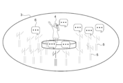
- FIG. 2 is a schematic diagram showing an example of a virtual space configured by the distribution system 100. It can be said that the virtual space 3 is a shared space shared by a plurality of viewers 2 during the virtual experience.
- a performer model 4, which is a virtual model of the performer 1, is arranged in the virtual space 3. As described above, the performer model 4 is a volumetric model that reproduces the performer 1 in the real space, and operates in the same manner as the movement of the performer 1.
- the performer model 4 arranged on the stage in the virtual space 3 is schematically illustrated.
- a viewer model 5 which is a virtual model of the viewer 2 is arranged.
- the viewer model 5 is, for example, a virtual avatar that operates according to the movement of the viewer 2 detected by the motion sensor included in the client terminal 12.
- a plurality of viewer models 5 arranged so as to surround the stage are schematically illustrated.
- the voices and comments of the performer 1 and the viewer 2 are shared.
- an icon 6 representing a voice or a comment is schematically illustrated.
- the icon 6 including the comment input by the performer 1 and the viewer 2 is arranged corresponding to the virtual model of the person so that the person who input the comment can be known.
- the icon 6 may be arranged so that the speaker can be identified.
- an image (visual field image) corresponding to the view of the viewer model 5 in the virtual space 3 is displayed.
- NS This makes it possible to provide a virtual experience with a sense of reality as if the viewer 2 himself is in the live venue of the virtual space 3.
- the distribution server 10 generates an image of the virtual space 3 taken from the viewpoint of the virtual camera and distributes it as live content.
- the image taken by the virtual camera (the image taken from the viewpoint of the virtual camera) will be referred to as a virtual camera image.
- the virtual camera image is an image different from the above-mentioned field of view image.
- FIG. 3 is a schematic diagram for explaining shooting by a virtual camera.
- FIG. 4 is a schematic diagram showing an example of a virtual camera image.
- the virtual camera 20 is a camera virtually configured to move in the virtual space 3 and take a picture of the virtual space 3.
- the shooting position and shooting direction of the virtual camera 20 can be freely set in the virtual space 3.
- FIG. 3 schematically shows a virtual camera 20 that captures the virtual space 3 and a photographing path 21 (dotted line in the figure) of the virtual camera 20.
- the object representing the virtual camera 20 and the shooting path 21 is not displayed.
- the shooting target of the virtual camera 20 is the performer model 4 that operates in the virtual space 3. That is, it can be said that the virtual camera 20 is a camera that moves in the virtual space 3 and shoots the performer model 4.
- the virtual camera 20 moves along a shooting path 21 that wraps around from the left rear of the performer model 4 to the front.
- the shooting direction and the shooting magnification of the virtual camera 20 are appropriately controlled so that the performer model 4 falls within the shooting range of the virtual camera 20.
- a virtual camera image 22 obtained by shooting the performer model 4 from the front is generated.
- the virtual camera image 22 is an image obtained by shooting the performer model 4 by changing the shooting position and shooting direction in the virtual space 3 with time.
- the image (virtual camera image 22) of the performer model 4 taken by the virtual camera 20 is distributed as live content. As a result, each viewer 2 can watch a live music or the like performed in the virtual space 3 in real time.
- the positional relationship between the performer model 4 and the virtual camera 20 is monitored. Then, a collision avoidance process for avoiding a collision of the virtual camera 20 with the performer model 4 is executed according to the positional relationship between the performer model 4 and the virtual camera 20.
- the collision avoidance process is typically a process of controlling the behavior of the virtual camera 20 to cause the virtual camera 20 to execute an action of avoiding a collision with the performer model 4 (collision avoidance action).
- collision avoidance action the situation where the virtual camera 20 collides with the performer model 4 is avoided in advance, and it is possible to properly shoot the performer model 4 without generating "immersion image” or "penetration image”. ..
- the collision avoidance process will be described in detail later.
- FIG. 5 is a block diagram showing a functional configuration example of the photographing system 11 and the distribution server 10.
- the shooting system 11 and the distribution server 10 are distribution-side systems used by the distributor to distribute live content in the distribution system 100.
- a performer 1 who appears in a live performance or a business operator who plans live contents is a distributor.
- the photographing system 11 generates the data necessary for generating the volumetric model of the performer 1.
- the photographing system 11 includes a photographing unit 30 and a photographing processing unit 31.
- the photographing unit 30 includes a group of devices for photographing and sensing the performer 1, and is used, for example, in a photographing studio for photographing the performer 1.
- the photographing unit 30 has a multi-viewpoint image photographing unit 32 and a body position sensing unit 33.
- FIG. 6 is a schematic diagram showing a configuration example of the photographing unit 30.
- the multi-viewpoint video shooting unit 32 is a multi-camera unit including a plurality of cameras.
- FIG. 6 schematically shows N cameras (Cam (1) to Cam (N)) constituting the multi-viewpoint video shooting unit 32.
- the cameras are arranged at different positions from each other so as to shoot the performer 1 from all directions, for example. This makes it possible to generate a volumetric model in which the whole body of the performer 1 is synthesized.
- the multi-viewpoint video shooting unit 32 is a multi-viewpoint camera for volumetric shooting.
- the body position sensing unit 33 includes a sensor (motion sensor) for detecting the position of each part of the body of the performer 1.
- a wearable position sensor 33a, a depth camera 33b, and an infrared camera 33c are used as the body position sensing unit 33.
- the type of sensor used as the body position sensing unit 33 is not limited, and other motion sensors may be used. Further, these sensors may be used alone or in combination of all or a part of the sensors.
- the wearable position sensor 33a is a sensor that the performer 1 wears on the body and uses, and detects the position of the worn portion.
- the wearable position sensor 33a is attached to the left and right wrists of the performer 1, respectively.
- the depth camera 33b is a camera that captures a depth image of a shooting target (performer 1).
- the depth image is an image in which the distance (depth) to the shooting target is detected for each pixel. By using the depth image, it is possible to detect the position of each part of the body of the performer 1.
- the infrared camera 33c is a camera that irradiates an imaged object with infrared rays and captures an infrared image.
- an infrared marker 34 that selectively reflects infrared rays is attached to the body of the performer 1, and an infrared image of the performer 1 is taken. It is possible to detect the position of the mounting portion from the state of the infrared marker 34 in the infrared image captured in this way.
- FIG. 7 is a schematic diagram showing an example of a photography studio.
- the shooting studio is, for example, a greenback studio that uses green members for the background and floor.
- a pole for fixing each camera of the multi-viewpoint video shooting unit 32 is installed.
- Cam (1) and Cam (2) are fixed to the upper and lower tiers of the left pole in the figure
- Cam (3) and Cam (4) are fixed to the upper and lower tiers of the right pole. Is fixed.
- an infrared camera 33c is arranged at the upper end of each pole.
- each pole is provided with a light 35 for lighting. A plurality of such poles are arranged so as to surround the performer 1, for example.
- a depth camera 33b is arranged in the shooting studio.
- the distance between the depth camera 33b and the performer 1 is set to a predetermined value (for example, about 0.5 m to 5.5 m) so that a depth image in a required range can be captured.
- the specific configuration of the shooting studio is not limited.
- a shooting device capable of performing shooting and sensing necessary for generating the performer model 4 may be appropriately used.
- the photographing processing unit 31 is a data processing device that integrates the outputs of the photographing unit 30 to generate data necessary for generating a volumetric model.
- a computer such as a PC (Personal Computer) is used.
- the shooting processing unit 31 may be configured by the distribution server 10 described later.
- the shooting processing unit 31 has a camera image generation unit 36, a multi-viewpoint video streaming processing unit 37, a body position information generation unit 38, and a 3D model position information generation unit 39 as functional blocks.
- the camera image generation unit 36 reads the output of the multi-viewpoint video shooting unit 32 and generates a camera image 26 shot for each camera.
- the camera image 26 is an image of the performer 1 taken at the same timing from a plurality of viewpoints.
- FIG. 5 schematically shows a camera image 26 taken by each camera (Cam (1) to Cam (N)).
- the multi-viewpoint video streaming processing unit 37 generates the multi-viewpoint video 27 of the performer 1 based on the plurality of camera images 26, and executes the streaming processing for the multi-viewpoint video 27.
- the multi-viewpoint video 27 is generated by synchronizing the shooting timings of the camera images 26 and arranging them along the time axis. Streaming processing such as compression / conversion is executed for the multi-viewpoint video 27.
- FIG. 5 schematically shows an example of the multi-viewpoint video 27 by a series of images along the time axis.
- the body position information generation unit 38 reads the output of the body position sensing unit 33 and generates body position information indicating the position of each part of the body of the performer 1. For example, the position information of the portion where the wearable position sensor 33a is attached, the depth image 28 of the performer 1 taken by the depth camera 33b, the infrared image of the performer 1 (infrared marker 34) taken by the infrared camera 33c, and the like are the body. Generated as position information.
- FIG. 5 schematically shows a depth image 28 of the performer 1 as an example of body position information.
- the 3D model position information generation unit 39 generates model position information representing the position of each part of the performer model 4 (here, the volumetric model of the performer 1) based on the above-mentioned body position information. Specifically, the bone estimation process is executed based on the body position information, and the bone data 29 that estimates the position and posture of the skeleton of the performer 1 is calculated. This bone data 29 is used as model position information of the performer model 4.
- FIG. 5 schematically shows an example of bone data 29.
- a method for sensing the body position of the performer 1 a method other than the above-mentioned bone estimation may be used.
- position estimation of each part of the body by image recognition, three-dimensional position estimation using machine learning, or the like may be used.
- a motion capture technique based on infrared detection using an infrared camera and an infrared marker may be used.
- the distribution server 10 includes a network transmission unit 40, a storage unit 41, and a server control unit 42.
- the network transmission unit 40 is a communication module that performs network communication with other devices via the Internet 13.
- the network transmission unit 40 has, for example, a data transmission function for transmitting data (live content or the like) generated by the distribution server 10 and a data reception function for receiving data transmitted from the client terminal 12 via the Internet 13. .
- the specific configuration of the network transmission unit 40 is not limited, and various communication modules compatible with wired LAN, wireless LAN, optical communication, and the like may be used.
- the storage unit 41 is a non-volatile storage device.
- a recording medium using a solid-state element such as an SSD (Solid State Drive) or a magnetic recording medium such as an HDD (Hard Disk Drive) is used.
- the type of recording medium used as the storage unit 41 is not limited, and for example, any recording medium for recording data non-temporarily may be used.
- the control program according to this embodiment is stored in the storage unit 41.
- the control program is, for example, a program that controls the operation of the entire distribution server 10.
- the information stored in the storage unit 41 is not limited.
- the server control unit 42 controls the operation of the distribution server 10.
- the server control unit 42 has a hardware configuration necessary for a computer such as a CPU and a memory (RAM, ROM). Various processes are executed by the CPU loading the control program stored in the storage unit 41 into the RAM and executing the control program.
- the server control unit 42 corresponds to the information processing device according to the present embodiment.
- server control unit 42 for example, a device such as a PLD (Programmable Logic Device) such as an FPGA (Field Programmable Gate Array) or another device such as an ASIC (Application Specific Integrated Circuit) may be used. Further, for example, a processor such as a GPU (Graphics Processing Unit) may be used as the server control unit 42.
- a PLD Programmable Logic Device
- FPGA Field Programmable Gate Array
- ASIC Application Specific Integrated Circuit
- a processor such as a GPU (Graphics Processing Unit) may be used as the server control unit 42.
- the CPU of the server control unit 42 executes the program (control program) according to the present embodiment, so that the content data generation unit 43 and the virtual camera control unit 44 are realized as functional blocks. Then, the information processing method according to the present embodiment is executed by these functional blocks.
- dedicated hardware such as an IC (integrated circuit) may be appropriately used.
- the content data generation unit 43 generates content data here.
- the content data is, for example, data necessary for constructing the virtual space 3.
- the content data includes data related to virtual objects (performer model 4, viewer model 5, stage set, etc.) arranged in the virtual space 3, audio data in the virtual space 3, comments by the performer / viewer, and the like.
- the content data generation unit 43 includes a performer model generation unit 45 and a viewer model generation unit 46.
- the performer model generation unit 45 generates a performer model 4 which is a virtual model of the performer 1. Specifically, the data of the volumetric model (performer model 4) of the performer 1 is generated based on the multi-viewpoint video 27 and the bone data 29 of the performer 1 output from the shooting system 11. For example, the shape data and texture data of the performer model 4 are generated from the multi-viewpoint video 27. Further, for example, the motion data of the performer model 4 is generated from the bone data 29. In addition, the performer model generation unit 45 calculates the placement position of the performer model 4 in the virtual space 3 according to the movement of the performer 1, the live performance, and the like.
- the viewer model generation unit 46 generates a viewer model 5 which is a virtual model of the viewer 2. Specifically, data representing the positions of each part of the body (head, hands, etc.) of the viewer 2 is acquired from each client terminal 12, and the data of the viewer model 5 (virtual avatar, etc.) is obtained based on these data. To generate.
- the design of the viewer model 5 or the like may be specified by the viewer 2, for example, or the default design may be used. Further, the viewer model generation unit 46 calculates the placement position of each viewer model 5 in the virtual space 3 according to the operation of the viewer 2 and the like.
- the content data generation unit 43 generates data of other virtual objects arranged in the virtual space 3, audio data of the performer 1 and the viewer 2, video performance data of music, and the like as content data.
- the specific content of the content data is not limited.
- the content data generated by the content data generation unit 43 is distributed to each client terminal 12 as live content.
- the virtual camera control unit 44 controls the virtual camera 20 to generate a virtual camera image 22 (see FIG. 4) in which the virtual space 3 is captured by the virtual camera 20.
- a performer model 4 and a viewer model 5 generated by the content data generation unit 43 are arranged on the virtual space 3, and a virtual live venue is reproduced.
- the virtual camera control unit 44 controls the behavior of the virtual camera 20 in the virtual space 3 configured in this way.
- the virtual camera control unit 44 relates to the performer model 4 according to the positional relationship between the performer model 4 operating in the virtual space 3 and the virtual camera 20 that moves in the virtual space 3 to shoot the performer model 4. A collision avoidance process for avoiding a collision of the virtual camera 20 is executed.
- the virtual camera control unit 44 corresponds to a shooting control unit.
- the positional relationship between the performer model 4 and the virtual camera 20 is typically expressed using the distance (relative distance) between the performer model 4 and the virtual camera 20.
- the distance between the performer model 4 and the virtual camera 20 may be a current value or a predicted value.
- the distance between the performer model 4 and the virtual camera 20 is monitored, and when the value satisfies a predetermined condition, the collision avoidance process is executed.
- a collision avoidance process a process of sequentially controlling the behavior of the virtual camera 20 is executed so that the distance between the performer model 4 and the virtual camera 20 satisfies a predetermined condition.
- the virtual camera control unit 44 generates a virtual camera image 22. For example, an image seen from a virtual camera 20 moving in the virtual space 3 during a live concert is generated at a predetermined frame rate. Based on these images, a virtual camera image 22 that captures the virtual space 3 during live performance is generated.
- the virtual camera image 22 is delivered to each client terminal 12 as live content. As described above, in the present embodiment, the image (virtual camera image 22) taken by the virtual camera 20 is delivered in real time.
- FIG. 8 is a block diagram showing a functional configuration example of the client terminal 12.
- the client terminal 12 has a network transmission unit 50, a storage unit 51, and a terminal control unit 52.
- the client terminal shown in FIG. 8 includes an HMD 14 and a hand controller 15.
- the client terminal 12 functions as a display device.
- the viewer 2 who uses the client terminal 12 is described as an experiencer, and the viewer 2 other than the experiencer is described as another viewer.
- the HMD 14 is a display device worn by the experiencer on the head.
- the HMD 14 has a display 53, a voice output unit 54, a voice input unit 55, and an HMD operation sensor 56.
- the display 53 is arranged so as to cover the field of view of the experiencer.
- As the display 53 for example, a liquid crystal display or an organic EL display is used.
- the audio output unit 54 is an element that reproduces audio from a speaker, headphones, or the like.
- the voice input unit 55 is an element that detects voice such as a microphone.
- the HMD operation sensor 56 is a sensor that detects the position and orientation of the HMD 14 main body, and includes, for example, an acceleration sensor, a gyro sensor, an orientation sensor, and the like.
- the display 53 corresponds to a display unit that displays an image taken by the virtual camera.
- the hand controller (HC) 15 is an operation device that accepts an input operation according to the movement of the hand of the experiencer.
- the hand controller 15 a grip-type device that is gripped and operated by the experiencer and a wearable device that is worn and used by the experiencer's hand are used.
- the hand controller 15 has a vibration generating unit 57 and an HC operation sensor 58.
- the vibration generation unit 57 is a device that generates vibration, and for example, a voice coil motor, an eccentric motor, or the like is used.
- the HC operation sensor 58 is a sensor that detects the position and orientation of the main body of the hand controller 15.
- the network transmission unit 50 is a communication module that performs network communication with other devices via the Internet 13.
- the network transmission unit 50 has, for example, a data reception function for receiving data generated by the distribution server 10 and a data transmission function for transmitting data generated by the client terminal 12.
- the storage unit 51 is a non-volatile storage device, and a recording medium such as an SSD or an HDD is used.
- the storage unit 51 stores a control program that controls the operation of the entire client terminal 12. In addition, the information stored in the storage unit 51 is not limited.
- the terminal control unit 52 controls the operation of the client terminal 12.
- the terminal control unit 52 has a hardware configuration necessary for a computer such as a CPU and a memory (RAM, ROM). Various processes are executed by the CPU loading the control program stored in the storage unit 51 into the RAM and executing the control program.
- the specific configuration of the terminal control unit 52 is not limited. In the present embodiment, various functional blocks are realized by the CPU of the terminal control unit 52 executing the control program stored in the storage unit 51.
- the terminal control unit 52 has a video acquisition unit 60, a performer data analysis unit 61, another viewer data analysis unit 62, timing synchronization units 63a to 63c, and experiencer data as functional blocks. It has an output unit 64, a 3D object control unit 65, a 3D object collision detection unit 66, and a display control unit 67. Further, in the area surrounded by the dotted line in FIG. 8, data (network communication data group) transmitted / received via the Internet 13 is schematically illustrated.
- the video acquisition unit 60 acquires the virtual camera image 22 captured by the virtual camera 20 via the network transmission unit 50 and outputs it to the display control unit 67.
- FIG. 8 schematically shows a virtual camera image 22 output to the display control unit 67.
- the image acquisition unit 60 acquires an image (virtual camera image 22) taken by the virtual camera 20 that operates according to such a collision avoidance process.
- the image acquisition unit 60 corresponds to an image acquisition unit.
- the performer data analysis unit 61 acquires data related to the performer 1 via the network transmission unit 50, analyzes the acquired data, and generates performer data (performer video data, performer audio stream, performer metadata).
- the performer video data is, for example, data representing the appearance (shape / texture) of the performer model 4.
- the performer voice stream is, for example, streaming data of the voice or music of the performer 1.
- the performer metadata is, for example, text data such as body position data (bone data 29) of the performer model 4 and comments of the performer 1.
- the body position data is, for example, data representing the position and posture of the head and both hands, and data representing each part in 6DoF (Degree of Freedom) or 3DoF is used.
- the performer data generated by the performer data analysis unit 61 is output to the timing synchronization unit 63a.
- the other viewer data analysis unit 62 acquires data related to other viewers other than the experiencer via the network transmission unit 50, analyzes the acquired data, and performs other viewer data (other viewer audio stream, other viewer). (Metadata) is generated.
- the other viewer audio stream is streaming data of the audio of another viewer.
- the other viewer metadata is, for example, data (bone data or the like) of a virtual avatar (viewer model 5) used by another viewer, or text data such as a comment of another viewer.
- the other viewer data generated by the other viewer data analysis unit 62 is output to the timing synchronization unit 63b.
- the timing synchronization unit 63a synchronizes the timing of the performer data (performer video data, performer audio stream, performer metadata) generated by the performer data analysis unit 61.
- FIG. 8 schematically illustrates performer data synchronized with the timing.
- graphic data performer video data, bone data 29, comments, etc.
- data related to audio is output to the audio output unit 54 of the HMD 14.
- the timing synchronization unit 63b synchronizes the timing of other viewer data (other viewer audio stream, other viewer metadata) generated by the other viewer data analysis unit 62.
- FIG. 8 schematically shows other viewer data synchronized with the timing.
- data related to graphics is output to the 3D object control unit 65.
- data related to audio is output to the audio output unit 54 of the HMD 14.
- the timing synchronization unit 63c generates the experiencer data (experiencer voice stream, experiencer metadata) regarding the experiencer who uses the client terminal 12 so that the timing is synchronized.
- the experience-based audio stream is streaming data of the experience-based audio, and is generated based on the output of the audio input unit 55 of the HMD 14.
- the experiencer metadata is, for example, data (bone data or the like) of a virtual avatar (viewer model 5) used by the experiencer.
- the virtual avatar data is generated based on the output of the HMD operation sensor 56 of the HMD 14 and the HC operation sensor 58 of the hand controller 15.
- text data such as the experiencer's comment may be generated based on character input, voice recognition, or the like.
- the experience data output unit 64 compresses and converts the experience data to generate experience data for transmission. This data is transmitted to the distribution server 10 via the network transmission unit 50. In the distribution server 10, for example, a viewer model 5 or the like corresponding to each viewer 2 is generated based on the experiencer data transmitted from each client terminal 12.
- the 3D object control unit 65 creates virtual objects (3D objects) such as the performer model 4 and the viewer model 5, and constitutes a virtual space 3 (see FIG. 2) in which the virtual objects are arranged.
- the performer model 4 (the volumetric model of the performer 1) is generated based on the output of the timing synchronization unit 63a.
- a viewer model 5 used by other viewers is generated based on the output of the timing synchronization unit 63b.
- the viewer model 5 (experiencer's virtual avatar) used by the experiencer is generated based on the outputs of the HMD motion sensor 56 and the HC motion sensor 58.
- icons and the like representing comments of the performer 1, other viewers, and the experiencer are arranged.
- the data related to the virtual space 3 configured by the 3D object control unit 65 is output to the 3D object collision detection unit 66 and the display control unit 67.
- the 3D object collision detection unit 66 detects a collision (contact) of a virtual model in the virtual space 3. Specifically, a collision between the viewer model 5 used by the experiencer and another virtual object (for example, the performer model 4 or another viewer model 5) is detected. Further, when the collision between the models is detected in the 3D object collision detection unit 66, a vibration signal corresponding to the collision is generated. The generated vibration signal is output to the vibration generation unit 57 of the hand controller 15.
- the display control unit 67 controls the display of the virtual space 3 on the client terminal 12 (here, the display 53 of the HMD 14). Specifically, an image output to the display 53 (hereinafter referred to as an output image) is appropriately generated.
- the display control unit 67 generates a visual field image showing the visual field of the viewer model 5 used by the viewer based on the data of the virtual space 3.
- the virtual camera image 22 taken by the virtual camera 20 is input to the display control unit 67.
- the field of view image and the virtual camera image 22 are switched and used as the output image. For example, the view image and the virtual camera image 22 are switched according to a predetermined switching operation or the like by the experiencer.
- the method of generating the output video is not limited.
- the client terminal 12 when the client terminal 12 is provided with a plurality of displays, the field of view image and the virtual camera image 22 may be output individually. Further, when the viewer model 5 or the like is not used, a configuration may be used in which only the virtual camera image 22 is output.
- the distribution server 10 is not limited to the case where the virtual camera image 22 is generated, and for example, the virtual camera image 22 may be generated by the client terminal 12. In this case, for example, the virtual space 3 configured by the client terminal 12 is photographed by the virtual camera 20. In this case, the client terminal 12 executes the collision avoidance process of the virtual camera 20 described below.
- the operation of the virtual camera control unit 44 of the distribution server 10 will be specifically described.
- the virtual camera control unit 44 monitors the positional relationship between the performer model 4 and the virtual camera 20 in the virtual space 3. Based on this monitoring result, a state in which a collision between the performer model 4 and the virtual camera 20 is likely to occur is detected in advance.
- the virtual camera control unit 44 detects the proximity state between the performer model 4 and the virtual camera 20 based on the positional relationship between the performer model 4 and the virtual camera 20. Then, when the proximity state is detected, the collision avoidance process is executed.
- the proximity state is a state in which a collision between the performer model 4 and the virtual camera 20 is likely to occur because, for example, the performer model 4 and the virtual camera 20 are in close proximity to each other. Therefore, when the proximity state is detected, the collision avoidance process is executed in order to avoid the collision of the virtual camera 20 with the performer model 4 in advance.
- FIG. 9 is a schematic diagram showing an example of a proximity state.
- the virtual camera control unit 44 detects a state in which the relative distance between the performer model 4 and the virtual camera 20 is equal to or less than a predetermined threshold value R as a proximity state.
- the relative distance between the performer model 4 and the virtual camera 20 is, for example, the distance between the reference point of the performer model 4 and the reference point of the virtual camera 20.
- the reference point of the virtual camera 20 is typically the viewpoint (shooting position) of the virtual camera 20.
- the reference point of the performer model 4 is set, for example, at the center of gravity of the performer model 4 (center position of the model).
- the relative distance can be easily calculated, and the calculation required for monitoring the relative distance (positional relationship). It is possible to suppress resources.
- a reference point may be set on the surface of the performer model 4. In this case, for example, the distance from the viewpoint of the virtual camera 20 to the surface of the nearest performer model 4 is calculated as a relative distance. This makes it possible to reliably detect the close state of the virtual camera 20 regardless of the shape, size, and the like of the performer model 4.
- the relative distance between the performer model 4 and the virtual camera 20 may be a current value or a predicted value.
- the current value of the relative distance is calculated based on, for example, the current position of each reference point of the performer model 4 and the virtual camera 20.
- the predicted value of the relative distance is calculated based on, for example, the predicted position of each reference point of the performer model 4 and the virtual camera 20.
- the predicted position of the reference point of the performer model 4 is estimated based on, for example, the movement prediction using the current moving direction and the moving speed of the performer model 4.
- the predicted position of the reference point of the virtual camera 20 is estimated based on the shooting path of the virtual camera 20. By using the predicted value, it is possible to surely avoid the collision between the performer model 4 and the virtual camera 20.
- the threshold value R is the minimum distance (permissible close-up photography) at which the virtual camera 20 can approach the performer model 4 and perform photography.
- the threshold value R is set to, for example, about 2 m on a life-sized scale. Not limited to this, the threshold value R may be appropriately set according to the performer model 4, the type of performance, and the like.
- FIG. 10 is a schematic diagram showing an example of a collision avoidance process for changing a shooting path.
- FIG. 10 schematically shows a shooting path 21 of the virtual camera 20 set for shooting the performer model 4.
- the photographing path 21 includes a plurality of relay points.
- the virtual camera control unit 44 moves the virtual camera 20 so as to pass through these relay points in a preset order, and shoots the performer model 4.
- the shooting path 21 is a path set so that the virtual camera 20 passes through a plurality of relay points in order.
- the photographing path 21 is set so as to pass through the relay points P1, P2, P3, and P4 in this order.
- the virtual camera 20 moves, for example, along a straight line connecting each relay point.
- the route between the relay points may be set in a curved shape. This time.
- the shooting direction of the virtual camera 20 is appropriately adjusted so that the performer model 4 falls within the shooting range (angle of view).
- a passing time at which the virtual camera 20 should pass through the relay point is set at each relay point.
- the transit times T1, T2, T3, and T4 are set at the relay points P1, P2, P3, and P4, respectively. Therefore, the virtual camera 20 is moved so as to pass the relay point P1 at the time T1, the relay point P2 at the time T2, the relay point P3 at the time T3, and the relay point P4 at the time T4.
- the shooting path 21 is a path in which the passing time of the virtual camera 20 is set for each of the plurality of relay points.
- the shooting path 21 is appropriately set so that the performer model 4 and the virtual camera 20 do not collide with each other, assuming the position of the performer model 4.
- various camera works in detail according to the content of the performance performed by the performer model 4 (performer 1).
- a shooting path 21 is set according to a camera work schedule such as a time for shooting with the facial expression of the performer model 4 up and a time for shooting the entire image of the performer model 4. NS.
- the important relay point is, for example, a relay point for which shooting is to be performed reliably even in a live performance, and may be appropriately set by the designer (performer, creator, director, etc.) of the shooting path 21.
- a relay point for photographing a specific pose of the performer model 4 or the state of the performer model 4 in the rust portion of the music is set as an important relay point.
- the method of setting the shooting path 21 is not limited.
- the photographing path 21 may be automatically set.
- the designer sets a rough movement route for the virtual camera 20. Based on this rough movement route, the final shooting route (relay point and passing time) of the virtual camera 20 is automatically set according to the scale of the content and the movement of the performer 1.
- the position of the performer model 4 changes sequentially according to the movement of the performer 1, the live performance, and the like. Therefore, in the case of live distribution, the position of the performer model 4 may move larger than the assumed value when the shooting path 21 is set.
- the virtual camera control unit 44 becomes a movement target of the virtual camera 20 so that the collision between the performer model 4 and the virtual camera 20 is avoided when the proximity state is detected.
- Change the relay point That is, the relay point, which has been the movement target of the virtual camera 20 until then, is changed to another relay point at the timing when the proximity state is detected.
- the shooting path 21 of the virtual camera 20 is changed to a path toward the changed relay point.
- the process of changing the relay point is the collision avoidance process of changing the photographing path 21. This makes it possible to avoid a situation in which the virtual camera 20 collides with the performer model 4 in advance.
- the relay points are directed to the closest relay points in which collision does not occur.
- the shooting path 21 is changed. That is, when the proximity state is detected, a shortcut to the relay point at the shortest distance on the photographing path 21 where collision can be avoided is performed.
- This collision avoidance process includes the following processes.
- -A monitoring process for detecting the proximity state by monitoring the trajectory of the virtual camera 20 in real time according to the positional relationship between the performer model 4 and the virtual camera 20.
- -A route change process in which when a proximity state is detected, a relay point having the closest order in which a collision does not occur is selected, and the shooting route 21 is changed so that the route travels toward the relay point.
- -Speed adjustment processing for adjusting the moving speed of the virtual camera 20 by back calculation from the increase / decrease in the moving distance of the virtual camera 20 due to the change of the shooting path 21.
- the next moving target of the virtual camera 20 that has passed the relay point P1 at time T1 is set to the relay point P2. Then, the virtual camera 20 is moved from the relay point P1 toward the relay point P2 so as to reach the relay point P2 at the time T2.
- the relative distance between the performer model 4 and the moving virtual camera 20 is constantly calculated, and the presence or absence of a proximity state is monitored based on the relative distance. Specifically, it is determined whether or not the relative distance is equal to or less than the threshold value R. For example, it is assumed that the proximity state is detected because the performer model 4 has moved.
- the relative distance between the performer model 4 and the virtual camera 20 becomes equal to or less than the threshold value R, and the proximity state is detected.
- the route change process is executed.
- the closest relay points in which collision does not occur are selected.
- the relay points that the virtual camera 20 has not passed through are selected in the order of closeness, and it is determined whether or not a collision occurs when the route is changed toward each relay point. Then, the relay point for which it is first determined that no collision does not occur is selected as the next movement target of the virtual camera 20.
- the determination of whether or not a collision occurs is executed based on, for example, the current position and movement prediction of the performer model 4, the planned movement route (action schedule) of the performer model 4, and the like.
- the relay points P2, P3, and P4 are relay points that the virtual camera 20 has not passed through.
- the relay point P2 when the virtual camera 20 is moved toward the relay point P2, a collision with the performer model 4 may occur.
- the relay point P3 is set as the next movement target of the virtual camera 20 as the relay point having the closest order in which the collision does not occur.
- the movement target of the virtual camera 20 is set by the virtual camera control unit 44 to the nearest relay point capable of avoiding the collision between the performer model 4 and the virtual camera 20. ..
- the method of changing the relay point is not limited, and for example, a relay point having a short distance in the virtual space 3 may be selected instead of the order of the shooting paths 21. This makes it possible to quickly return to the original shooting path 21.
- the method of changing the relay point is not limited.
- a relay point may be newly added so that the virtual camera 20 does not collide with the performer model 4, and the virtual camera 20 may be moved toward the added relay point. That is, by increasing the number of relay points, the performer model 4 may be bypassed and the collision between the performer model 4 and the virtual camera 20 may be avoided.
- the virtual camera control unit 44 adjusts the moving speed of the virtual camera 20 that moves on the changed shooting path 21 based on the passing time set at the relay point. For example, by changing the relay point, the moving distance of the virtual camera 20 changes. Therefore, if the moving speed up to that point is maintained, the shooting (camera work) schedule may shift. The moving speed of the virtual camera 20 is changed with reference to the passing time of the relay point so that such a schedule shift does not occur. This makes it possible to prevent inconsistencies in the scale of the content video.
- the virtual camera control unit 44 adjusts the moving speed of the virtual camera according to the passing time of the important relay point included in the changed shooting path 21. Specifically, the moving speed of the virtual camera 20 is increased or decreased so that the important relay point can be passed at the passing time set for the important relay point.
- the moving speed of the virtual camera 20 is adjusted so that the virtual camera 20 passes through the relay point P3 at the passing time T3 set at the relay point P3.
- the moving speed is set to be small when the moving distance is reduced, and the moving speed is set to be large when the moving distance is increased.
- the moving speed of the virtual camera 20 is such that the virtual camera 20 passes through the relay point P4 at the passing time T4 set in the relay point P4. Is adjusted.
- the timing of passing through the relay point P3 does not necessarily have to be the time T3.
- the method of adjusting the moving speed of the virtual camera 20 is not limited.
- the moving speed may be adjusted according to the passing time of the changed relay point (relay point P3 in FIG. 10) without referring to the important relay point or the like.
- the passing time of the remaining relay points may be appropriately adjusted according to the total playing time and the like.
- the moving speed of the virtual camera 20 is set according to the adjusted passing time. This makes it possible to suppress an unnatural increase or decrease in the moving speed, for example.
- FIG. 11 is a flowchart of the collision avoidance process shown in FIG.
- the virtual camera 20 is moved so as to pass the next relay point at a predetermined time (step 101). For example, the position of the performer model 4 is monitored, and the relative distance to the virtual camera 20 is calculated based on the monitoring result. At this time, the moving speed of the virtual camera 20 is set so as to reach the relay point at the passing time of the relay point set as the moving target.
- step 102 It is determined whether or not the positional relationship between the performer model 4 and the virtual camera 20 is in a close state (step 102).
- the determination of the proximity state is performed, for example, according to the method described with reference to FIG. If the proximity state is not detected (No in step 102), step 105, which will be described later, is executed.
- the shooting path of the virtual camera 20 is changed to the relay point closest to the order in which the collision does not occur (step 103). For example, when the route is changed to a relay point that the virtual camera 20 has not passed through, it is determined whether or not the collision can be avoided, and the relay point having the closest order in which the collision can be avoided is selected. Then, a shooting path 21 that moves toward the selected relay point is newly set.
- the moving speed of the virtual camera 20 is adjusted so as to pass through the important relay point at a predetermined time (step 104). For example, when the moving distance to the important relay point is reduced, the moving speed is set to be small, and when the moving distance is increased, the moving speed is set to be large. That is, the moving speed of the virtual camera 20 is set by back calculation from the changed moving distance.
- step 105 When the moving speed is adjusted, it is determined whether or not the virtual camera 20 has arrived at the final relay point (step 105).
- the final relay point is the last relay point set in the shooting path 21.
- the virtual camera 20 has not arrived at the final relay point (No in step 105)
- the shooting path 21 is changed, the relay point that is the movement target in step 101 is changed to the newly set relay point, and the virtual camera 20 moves at the movement speed set in step 104. Will be done.
- the shooting end time is a time when shooting by the virtual camera 20 ends.
- the shooting end time is appropriately set according to, for example, the performance schedule of the performer model 4 (performer). If the shooting end time has not been reached (No in step 106), shooting from the final relay point is continued. When the shooting end time is reached (Yes in step 106), the shooting by the virtual camera 20 ends, and the live broadcast is completed.
- FIG. 12 is a schematic diagram showing another example of the collision avoidance process for changing the photographing path.
- the virtual camera control unit 44 becomes a movement target of the virtual camera 20 so that the collision between the performer model 4 and the virtual camera 20 is avoided when the proximity state is detected.
- Change at least part of the route to the relay point That is, the virtual camera 20 is moved along a new route for reaching the relay point that was the movement target of the virtual camera 20.
- the shooting path 21 of the virtual camera 20 is changed from the previous route toward the next relay point (for example, the route going straight to the next relay point) to a new route.
- This new route may be a route that returns to the middle of the route to the next relay point, or may be a route that goes directly to the next relay point without passing through the previous route. good.
- the collision avoidance process for changing the route between the relay points is executed. This makes it possible to avoid a situation in which the virtual camera 20 collides with the performer model 4 in advance.
- the performer model 4 is bypassed while monitoring the performer model 4.
- the virtual camera 20 is moved along the detour route 23. That is, the virtual camera control unit 44 moves the virtual camera 20 along the detour route 23 that bypasses the performer model 4 from the point where the proximity state is detected.
- the detour route 23 is a route that changes according to the movement of the performer model 4.
- This collision avoidance process includes the following processes.
- -A monitoring process for detecting the proximity state by monitoring the trajectory of the virtual camera 20 in real time according to the positional relationship between the performer model 4 and the virtual camera 20.
- -A route change process that changes the shooting route 21 so that when a proximity state is detected, the performer model 4 is detoured while being monitored and the route travels toward the initial relay point.
- -Speed adjustment processing for adjusting the moving speed of the virtual camera 20 by back calculation from the increase / decrease in the moving distance of the virtual camera 20 due to the change of the shooting path 21.
- the monitoring process is executed in the same manner as the method described with reference to FIG. 10, for example.
- the virtual camera 20 heading from the relay point P1 to the relay point P2 reaches the point X at the time Tx, the relative distance between the performer model 4 and the virtual camera 20 becomes equal to or less than the threshold value R, and the proximity state is detected.
- NS the threshold value
- the route change process is executed.
- the movement of the virtual camera 20 is controlled so as to perform a detour to the initial relay point (relay point P2 in FIG. 12).
- the trajectory of the detour travel becomes the detour route 23.
- the virtual camera 20 is moved so as to bypass the performer model 4 and return to the original route to the relay point P2 from the detection point X where the proximity state is detected.
- the behavior of the virtual camera 20 is controlled so that the relative distance between the performer model 4 and the virtual camera 20 is kept constant. Therefore, it can be said that the detour route 23 is a route that keeps the relative distance between the performer model 4 and the virtual camera 20 constant.
- FIG. 12 schematically illustrates a detour running of the virtual camera 20 when the performer model 4 stays at a substantially constant position.
- the detour route 23 is an arc-shaped route that returns from the detection point X in the proximity state to the original route centering on the performer model 4.
- the detour route 23 does not always have an arc shape because the detour travel is performed according to the movement of the performer model 4.
- the virtual camera 20 during the detour travels away from the performer model 4 by a certain distance, and the collision between the performer model 4 and the virtual camera 20 is avoided. Further, the virtual camera 20 is moved so as to return to the original route. Therefore, it is possible to sufficiently suppress the deviation from the initially set camera work.
- the method of changing the route to the relay point that is the movement target is not limited.
- an arbitrary route that does not cause a collision connecting the point where the proximity state is detected and the relay point that is the movement target may be calculated and used as the detour route 23.
- a route in which a collision does not occur is appropriately calculated based on the current position of the performer model 4, movement prediction, action schedule, and the like.
- the speed adjustment process is executed.
- the speed adjustment process for example, the method described with reference to FIG. 10 can be applied.
- the moving speed of the virtual camera 20 that moves on the changed shooting route 21 (detour route 23) is adjusted based on the passing time set at the relay point.
- the moving speed of the virtual camera 20 is increased so that the virtual camera 20 reaches the relay point P2 by the passing time T2 of the relay point P2. This makes it possible to quickly return to the original shooting schedule.
- the moving speed of the virtual camera 20 is adjusted according to the passing time of the important relay point. For example, when the relay point P3 is an important relay point, the moving speed of the virtual camera 20 is increased so as to pass the relay point P3 at the time T3. In this case, the change in the moving speed is small as compared with the case where the speed is increased according to the passing time T2 of the relay point P2. This makes it possible to reliably shoot important scenes while avoiding unnatural speed increase and the like.
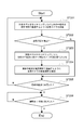
- FIG. 13 is a flowchart of the collision avoidance process shown in FIG.
- the virtual camera 20 is moved so as to pass the next relay point at a predetermined time (step 201).
- the performer model 4 is monitored, and the virtual camera 20 is detoured toward the initial relay point based on the monitoring result (step 203).
- the moving position of the virtual camera 20 is adjusted so that the relative distance between the performer model 4 and the virtual camera 20 is constant. Further, the moving direction of the virtual camera 20 is controlled so as to return to the original shooting path 21.
- any method that bypasses the performer model 4 may be used.
- the moving speed of the virtual camera 20 is adjusted so as to pass the important relay point at the specified time (step 204).
- the amount of increase / decrease in the moving distance of the virtual camera 20 is estimated according to the detour traveling method.
- the performer model 4 does not move
- the amount of increase / decrease in the movement distance when the virtual camera 20 is moved while keeping the relative distance to the performer model 4 constant is calculated.
- the moving speed required to pass the target relay point at a specified time is set by back calculation. Further, when the moving distance changes according to the movement of the performer model 4, the moving speed may be adjusted each time.
- step 205 it is determined whether or not the virtual camera 20 has arrived at the final relay point. If the virtual camera 20 has not arrived at the final relay point (No in step 205), the processes after step 201 are executed again.
- the virtual camera 20 arrives at the final relay point (Yes in step 205)
- the collision avoidance process mainly used when the virtual camera 20 moves along the preset shooting path 21 has been described. Even when such a shooting path 21 is not defined, it is possible to avoid a collision with the performer model 4 by appropriately controlling the behavior of the virtual camera 20.
- a method of controlling the virtual camera 20 that tracks and shoots the performer model 4 will be described.
- FIG. 14 is a schematic diagram showing another example of the collision avoidance processing of the virtual camera.
- FIG. 14 schematically shows a state of shooting by the virtual camera 20 that tracks the performer model 4 in accordance with the movement of the performer model 4 in the virtual space 3.
- a performer model 4 and a plurality of viewer models 5 are arranged in the virtual space 3.
- the performer model 4 can move freely in the virtual space 3.
- the viewer model 5 is arranged so as to surround the stage (rectangular area in the figure) provided in the virtual space 3.
- the virtual camera control unit 44 moves the virtual camera 20 so that the relative distance between the performer model 4 and the virtual camera 20 becomes constant as a collision avoidance process. That is, the movement of the virtual camera 20 is controlled so that the relative distance of the virtual camera 20 to the performer model 4 keeps a constant interval L (for example, 2 m or the like).
- This collision avoidance process includes the following processes.
- -A monitoring process that monitors the trajectory of the virtual camera 20 in real time and calculates the relative distance according to the positional relationship between the performer model 4 and the virtual camera 20.
- -A tracking process in which the virtual camera 20 is moved so that the relative distance becomes a constant interval L (shooting distance), and the performer model 4 is tracked and photographed.
- the relative distance between the performer model 4 and the virtual camera 20 is always calculated.
- the position of the performer model 4, which changes according to the movement of the performer 1, the production, and the like, and the position of the virtual camera 20 are read, and the relative distance is calculated.
- the position and direction in which the virtual camera 20 is moved are calculated so that the relative distance calculated in the monitoring process is the interval L, and the virtual camera 20 is moved according to the calculation result.
- the relative distance may temporarily become larger than the interval L due to the movement of the performer model 4.
- the virtual camera 20 is moved so as to approach the performer model 4 until the relative distance becomes the interval L.
- the virtual camera 20 is moved away from the performer model 4 until the relative distance reaches the interval L. That is, it can be said that the virtual camera control unit 44 performs feedback control that keeps the relative distance between the performer model 4 and the virtual camera 20 at the interval L with reference to the position of the performer model 4.
- the virtual camera 20 is moved so as to track the performer model 4 while maintaining a certain interval L with the performer model 4 without setting the relay point as the fixed shooting path 21. Then, the performer model 4 is photographed. As a result, the collision between the performer model 4 and the virtual camera 20 is avoided, and stable close-up photography can be continued.
- the direction in which the virtual camera 20 shoots the performer model 4 is not limited.
- the virtual camera 20 is moved according to the posture of the performer model 4 so as to shoot the performer model 4 from the front. Further, for example, the virtual camera 20 may be controlled so as to freely move around the performer model 4 within a range in which the relative distance is the interval L.
- the virtual camera 20 is allowed to "get into” or "pass through”. For example, for the viewer model 5 to which the virtual camera 20 comes into contact, the data constituting the model is removed so as not to be reflected in the shooting range of the virtual camera 20. That is, the viewer model 5 with which the virtual camera 20 comes into contact is treated as not being reflected by the virtual camera 20. This makes it possible to properly shoot the performer model 4. Further, since the moving range of the virtual camera 20 is not limited, it is possible to easily realize shooting or the like that is difficult in the real space. It is also possible to intentionally express "getting into” or "passing through” with respect to the viewer model 5 of the virtual camera 20 by using a silhouette or the like.
- the performer model 4 who was on the stage at time T1 moves away from the stage, and moves to the area where the viewer model 5 is arranged at time T2 and time T3.
- the virtual camera 20 is moved according to the performer model 4, and tracks and shoots the performer model 4 from a position separated by a certain interval L.
- the viewer model 5 that comes into contact with the virtual camera 20 is treated as not being reflected in the virtual camera 20. This makes it possible to take close-up shots properly even for performances (fan service, etc.) that are performed away from the stage.
- FIG. 15 is a flowchart of the collision avoidance process shown in FIG.
- the virtual camera 20 is moved so as to keep the relative distance at a constant interval L (step 301).
- the current positions of the performer model 4 and the virtual camera 20 are read, and the relative distance is calculated (monitoring process).
- the position and direction in which the virtual camera 20 moves are calculated so that the relative distance becomes the interval L, and the virtual camera 20 is moved based on the calculation result (tracking process).
- step 302 it is determined whether or not the shooting end time has been reached (step 302). If the shooting end time has not been reached (No in step 302), step 301 is executed again. When the shooting end time is reached (Yes in step 302), the shooting by the virtual camera 20 ends, and the live broadcast is completed. In this way, the tracking process (monitoring process) is continued until the shooting end time is reached.
- a control such as decelerating / stopping the virtual camera 20 for collision avoidance and tracking again after a certain distance may be executed may be executed.
- the virtual camera 20 is gradually decelerated and then stopped at a position where a collision does not occur.
- the relative distance between the performer model 4 and the virtual camera 20 may be smaller than the interval L.
- the virtual camera 20 waits for the relative distance between the virtual camera 20 and the performer model 4 to be separated by a certain distance (for example, the interval L), and then the tracking by the virtual camera 20. To start.
- this is a process of moving the virtual camera 20 by shifting the timing of changing the speed of the virtual camera 20 from the timing of changing the speed of the performer model 4. That is, the virtual camera control unit 44 delays the timing of the speed change of the virtual camera 20 with respect to the timing of the speed change of the performer model 4 so that the relative distance falls within a predetermined range.
- This makes it possible to realize camera work in which the shooting distance dynamically changes when the performer model 4 starts to move or stops. As a result, it becomes possible to convey the dynamic movement of the performer model 4 (performer 1).
- the method of tracking and shooting the performer model 4 is not limited, and any tracking method that can avoid a collision between the performer model 4 and the virtual camera 20 may be used.
- the collision avoidance process according to the positional relationship between the performer model 4 on the virtual space 3 and the virtual camera 20 that shoots the performer model 4 while moving in the virtual space 3 is performed. Will be executed. As a result, the collision between the performer model 4 and the virtual camera 20 is avoided in advance, and the performer model 4 can be properly photographed in the virtual space 3.
- FIG. 16 is a schematic diagram showing an example of a collision between a shooting target and a virtual camera.
- a shooting path 21 (P1 to P4) in which the virtual camera 20 approaches the shooting target 70 and performs close-up shooting is set.
- the shooting target 70 moves and overlaps with the shooting path 21, the virtual camera 20 may collide with the shooting target 70, and a immersive image or a penetrating image may be captured, resulting in a broadcasting accident. be.
- collision avoidance processing is executed according to the positional relationship between the performer model 4 to be photographed and the virtual camera 20.
- the collision avoidance process is, for example, a process of monitoring the position of the performer model 4 and controlling the movement of the virtual camera 20 so that the virtual camera 20 does not come too close to the performer model 4.
- the shooting path 21 of the virtual camera 20 when the shooting path 21 of the virtual camera 20 is preset, the proximity state between the performer model 4 and the virtual camera 20 is detected and the shooting path 21 is detected. Is changed. Further, as described with reference to FIG. 14 and the like, when the shooting path 21 and the like are not set, the virtual camera 20 is moved so as to track the performer model 4 at regular intervals L.
- FIGS. 10 and 12 a collision avoidance process for avoiding a collision with the performer model by changing the shooting path of the virtual camera has been mainly described.
- the present invention is not limited to this, and for example, a process of controlling the moving speed of the virtual camera to avoid a collision may be executed. For example, when a proximity state is detected, the speed is reduced or stopped without changing the path of the virtual camera. When the performer model moves and the proximity state is released, the virtual camera is accelerated according to the passing time of the relay point. It is also possible to change the shooting path when the performer model does not move and the proximity state continues for a certain period of time.
- the performer model may be photographed using a plurality of virtual cameras.
- each virtual camera is controlled to move in a different trajectory (shooting path).
- a display image for displaying the performer model is selected from the images (videos) taken by each virtual camera.
- the display image is, for example, an image finally displayed on each client terminal.
- a display image for displaying the performer model is displayed from the image taken by the virtual camera to another virtual camera. Is executed to switch to the captured image. For example, it is assumed that a proximity state is detected for a virtual camera that is taking a display image. In this case, the display image is switched to the image of another virtual camera that is not in the proximity state.
- the process of switching the virtual cameras so that the image at the moment of collision is not delivered is also included in the collision avoidance process in the present disclosure. This makes it possible to deliver natural live video without causing a broadcasting accident.
- the collision avoidance processing of the virtual camera has been described by taking as an example the case where the shooting target of the virtual camera is a live-action 3D model (volumetric model) of the performer.
- the shooting target of the virtual camera may be a CG3D model.
- a three-dimensional CG model virtual avatar that moves in conjunction with the movement of the performer is photographed by a virtual camera. Even in such a case, by using the above method, it is possible to sufficiently avoid the collision between the virtual camera and the CG model.
- this technology can also be applied to the distribution of entertainment content such as "sports live” and "variety programs".
- entertainment content such as "sports live” and "variety programs”.
- a sports venue is reproduced in a virtual space from data obtained by shooting sports performed in a real space. This enables free-viewpoint photography of sports venues with a virtual camera.
- the above-mentioned collision avoidance process is applied in order to avoid a collision between the player and the virtual camera.
- this technology may be applied when distributing contents in fields such as "distance education”, “distance lessons”, and “remote work support”.
- the work site is reproduced in the virtual space from the data obtained by photographing the work site where remote work is performed using a robot or the like.
- the virtual camera is moved so as to avoid a collision with the robot.
- the present technology is not limited to this, and can be applied to, for example, a case where content is generated based on data in which performance in a virtual space is recorded.
- a live video is generated after a live performance (for example, when the content production company and the company that shoots and edits the content are different)
- it has already been performed based on the data of the music live performed in the virtual space.
- the live music will be reproduced and shot with a virtual camera.
- this technique it is possible to easily generate a route of a virtual camera that avoids a collision between the performer model and the virtual camera.
- this technology functions as a path generation tool for a virtual camera or a shooting path design support tool.
- this technology can also adopt the following configurations.
- Collision avoidance for avoiding collision of the virtual camera with the target object according to the positional relationship between the target object operating in the virtual space and the virtual camera that moves in the virtual space and shoots the target object.
- the information processing apparatus according to (1) The shooting control unit detects a close state between the target object and the virtual camera based on the positional relationship between the target object and the virtual camera, and when the close state is detected, the collision avoidance process. Information processing device that executes.
- the shooting control unit is an information processing device that detects a state in which the relative distance between the target object and the virtual camera is equal to or less than a predetermined threshold value as the proximity state.
- the relative distance is an information processing device including a current value or a predicted value.
- the virtual camera shoots the target object along a preset shooting path, and the virtual camera shoots the target object.
- the imaging control unit is an information processing device that changes the imaging path as the collision avoidance process when the proximity state is detected.
- the shooting path is an information processing device that is a path set so that the virtual camera passes through a plurality of relay points in order.
- the information processing apparatus is an information processing device that changes a relay point that is a movement target of the virtual camera so that a collision between the target object and the virtual camera is avoided when the proximity state is detected.
- the information processing apparatus is an information processing device that sets a moving target of the virtual camera to a relay point having the closest order so as to avoid a collision between the target object and the virtual camera.
- the photographing control unit is at least a part of the route to the relay point which is the movement target of the virtual camera so that the collision between the target object and the virtual camera is avoided when the proximity state is detected. Information processing device to change.
- the shooting control unit is an information processing device that moves the virtual camera along a detour route that bypasses the target object from the point where the proximity state is detected.
- the detour route is an information processing device that keeps the relative distance between the target object and the virtual camera constant.
- the shooting route is a route in which the passing time of the virtual camera is set for each of the plurality of relay points.
- the shooting control unit is an information processing device that adjusts the moving speed of the virtual camera that moves the changed shooting path based on the passing time set at the relay point.
- the plurality of relay points include at least one important relay point.
- the shooting control unit is an information processing device that adjusts the moving speed of the virtual camera according to the passing time of the important relay point included in the shooting path after the change.
- the information processing apparatus according to any one of (2) to (13).
- the shooting control unit performs a display image for displaying the target object from an image taken by the virtual camera to an image taken by another virtual camera as the collision avoidance process.
- Information processing device to switch to.
- the information processing apparatus according to any one of (1) to (14).
- the shooting control unit is an information processing device that moves the virtual camera so that the relative distance between the target object and the virtual camera becomes constant as the collision avoidance process.
- the shooting control unit is an information processing device that delays the timing of the speed change of the virtual camera with respect to the timing of the speed change of the target object so that the relative distance falls within a predetermined range.
- the target object is an information processing device including a three-dimensional live-action model of the performer.
- the shooting control unit is an information processing device that delivers images shot by the virtual camera in real time. (19) Collision avoidance for avoiding collision of the virtual camera with the target object according to the positional relationship between the target object operating in the virtual space and the virtual camera that moves in the virtual space and shoots the target object.
- An image acquisition unit that acquires an image taken by the virtual camera that operates according to the collision avoidance process of A display device including a display unit for displaying an image taken by the virtual camera.
Landscapes
- Engineering & Computer Science (AREA)
- Theoretical Computer Science (AREA)
- Physics & Mathematics (AREA)
- Multimedia (AREA)
- General Physics & Mathematics (AREA)
- Software Systems (AREA)
- Signal Processing (AREA)
- Computer Vision & Pattern Recognition (AREA)
- Databases & Information Systems (AREA)
- General Engineering & Computer Science (AREA)
- Computer Graphics (AREA)
- Artificial Intelligence (AREA)
- Human Computer Interaction (AREA)
- Geometry (AREA)
- Health & Medical Sciences (AREA)
- Computing Systems (AREA)
- Evolutionary Computation (AREA)
- General Health & Medical Sciences (AREA)
- Medical Informatics (AREA)
- Radar, Positioning & Navigation (AREA)
- Remote Sensing (AREA)
- Computer Hardware Design (AREA)
- Processing Or Creating Images (AREA)
Abstract
Description
前記撮影制御部は、仮想空間で動作する対象オブジェクトと前記仮想空間を移動して前記対象オブジェクトを撮影する仮想カメラとの位置関係に応じて、前記対象オブジェクトに対する前記仮想カメラの衝突を回避するための衝突回避処理を実行する
前記画像取得部は、仮想空間で動作する対象オブジェクトと前記仮想空間を移動して前記対象オブジェクトを撮影する仮想カメラとの位置関係に応じて実行される、前記対象オブジェクトに対する前記仮想カメラの衝突を回避するための衝突回避処理に従って動作する前記仮想カメラが撮影した画像を取得する。
前記表示部は、前記仮想カメラが撮影した画像を表示する。
図1は、本技術の一実施形態に係る配信システムの構成例を示す模式図である。配信システム100は、仮想空間を利用したライブコンテンツをリアルタイムで配信するシステムである。
配信システム100は、配信サーバ10と、撮影システム11と、少なくとも1つのクライアント端末12とを有する。図1に示す構成では、配信サーバ10と各クライアント端末12とが、インターネット13を介して互いに通信可能に接続される。なお配信サーバ10と各クライアント端末12とがプライベートネットワーク等の専用のネットワーク回線を介して接続されてもよい。
以下では、仮想空間で音楽ライブ等が行われる場合を例に、配信システム100の概要について説明する。
仮想空間には、例えばライブコンテンツの主演となる演者1が操作する仮想モデルや舞台装置や背景等のCG(Computer Graphics)オブジェクトが配置される。演者1は、自身の仮想モデルを操作することで、仮想空間上で歌唱、ダンス、楽器演奏等の様々なパフォーマンスを行うことが可能である。
配信サーバ10は、このような仮想空間を構成し、仮想空間を撮影した画像、仮想空間の音声、仮想空間に配置される仮想オブジェクト(演者1の仮想モデルや他のオブジェクト等)に関するデータ等を、ライブコンテンツとして生成する。
なお、本開示において、画像とは、静止画像及び動画像を含む。以下では、主に仮想空間を撮影した動画像(映像)がライブコンテンツとして用いられる。
本実施形態では、演者1の仮想モデル(対象オブジェクト)として、演者1の3次元実写モデル(ボリュメトリックモデル)が用いられる。ボリュメトリックモデルは、現実空間の演者1をそのまま3次元CGとして再現した仮想モデルである。ボリュメトリックモデルを用いることで、現実空間での演者1のパフォーマンスをそのまま仮想空間上で再現することが可能となる。また演者1の仮想モデルは、異なる左右の視点から撮影されたステレオ撮像体として生成されてもよい。これにより現実空間の演者1を立体視することが可能となる。
クライアント端末12としては、例えばHMD14(Head Mounted Display)を備える装置が用いられる。HMD14を用いることで、視聴者2の視界を覆うように仮想空間の映像等を表示することが可能となる。この他、クライアント端末12として、装着型のARグラス(透過型HMD)や据え置き型のディスプレイを備える装置、タブレットやスマートフォン等の携帯型の端末装置等が用いられてもよい。
配信サーバ10では、各クライアント端末12から送信されたデータに基づいて、視聴者2の動作、音声、文字入力等を反映したライブコンテンツが生成される。これにより、視聴者は、仮想空間で開催される演者1のライブに参加することが可能となる。
仮想空間3には、演者1の仮想モデルである演者モデル4が配置される。演者モデル4は、上記したように、実空間の演者1を再現したボリュメトリックモデルであり、演者1の動きと同様に動作する。図2に示す例では、仮想空間3内のステージ上に配置された演者モデル4が模式的に図示されている。
以下では、仮想カメラが撮影した映像(仮想カメラの視点から撮影された映像)を仮想カメラ映像と記載する。仮想カメラ映像は、上記した視界映像とは異なる映像である。
図3は、仮想カメラによる撮影について説明するための模式図である。図4は、仮想カメラ映像の一例を示す模式図である。
仮想カメラ20は、仮想空間3内を移動して仮想空間3を撮影するように仮想的に構成されたカメラである。仮想カメラ20の撮影位置や撮影方向は、仮想空間3内で自由に設定することが可能である。
図3には、仮想空間3を撮影する仮想カメラ20と、仮想カメラ20の撮影経路21(図中の点線)とが模式的に図示されている。なお、実際に仮想空間3を構成する際には、仮想カメラ20や撮影経路21を表すオブジェクトは表示されない。
例えば図3に示すように、仮想カメラ20が演者モデル4の正面を通過する際には、図4に示すように、演者モデル4を正面から撮影した仮想カメラ映像22が生成される。
仮想カメラ20を用いた撮影では、撮影位置や撮影方向等についての制約が少ない。このため、例えば現実空間での撮影では難しいカメラワーク等を容易に実現することが可能となる。この結果、ダイナミックな映像表現を容易に実現することが可能となる。
また本実施形態では、仮想カメラ20により撮影された演者モデル4の画像(仮想カメラ映像22)がライブコンテンツとして配信される。これにより、各視聴者2は、仮想空間3で行われる音楽ライブ等をリアルタイムで鑑賞することが可能となる。
衝突回避処理は、典型的には、仮想カメラ20の挙動を制御して、演者モデル4との衝突を回避する行動(衝突回避行動)を仮想カメラ20に実行させる処理である。
これにより、仮想カメラ20が演者モデル4に衝突するといった事態が事前に回避され、「めり込み映像」や「貫通映像」等を発生させることなく、演者モデル4を適正に撮影することが可能となる。衝突回避処理については、後に詳しく説明する。
撮影システム11は、演者1のボリュメトリックモデルを生成するために必要なデータを生成する。図5に示すように、撮影システム11は、撮影部30と、撮影処理部31とを有する。
撮影部30は、演者1を撮影・センシングするための装置群を含み、例えば演者1を撮影するための撮影スタジオ内で用いられる。本実施形態では、撮影部30は、多視点映像撮影部32と、身体位置センシング部33とを有する。
多視点映像撮影部32は、複数のカメラを含むマルチカメラユニットである。図6には、多視点映像撮影部32を構成するN台のカメラ(Cam(1)~Cam(N))が模式的に図示されている。各カメラは、例えば演者1を全方位から撮影するように互いに異なる位置に配置される。これにより、演者1の全身を合成したボリュメトリックモデルが生成可能となる。このように、多視点映像撮影部32は、ボリュメトリック撮影用の複数視点カメラであると言える。
なお、身体位置センシング部33として用いるセンサの種類等は限定されず、他のモーションセンサが用いられてもよい。また、これらのセンサは、単独で用いられてもよいし、全て又は一部のセンサを組み合わせて用いることも可能である。
デプスカメラ33bは、撮影対象(演者1)のデプス画像を撮影するカメラである。デプス画像は、画素ごとに撮影対象までの距離(奥行)が検出された画像である。デプス画像を用いることで、演者1の身体の各部の位置を検出することが可能である。デプスカメラ33bとしては、例えばToFカメラ等が用いられる。
赤外線カメラ33cは、撮影対象に赤外線を照射して赤外画像を撮影するカメラである。赤外線カメラ33cを用いる場合、例えば赤外線を選択的に反射する赤外線マーカ34が演者1の身体に装着され、演者1の赤外画像が撮影される。このように撮影された赤外画像における赤外線マーカ34の状態から、装着部位の位置を検出することが可能である。
撮影スタジオには、例えば多視点映像撮影部32の各カメラを固定するポールが設置される。図7に示す例では、図中の左側のポールの上段及び下段に、Cam(1)及びCam(2)が固定され、右側のポールの上段及び下段に、Cam(3)及びCam(4)が固定される。また、各ポールの上端には、赤外線カメラ33cがそれぞれ配置される。さらに、各ポールには、照明用のライト35がそれぞれ設けられる。このようなポールが、例えば演者1を囲むように複数配置される。これにより、演者1を全方位から撮影することが可能となる。
また、撮影スタジオには、デプスカメラ33bが配置される。デプスカメラ33bと演者1との距離は、必要な範囲のデプス画像が撮影可能となるように、所定の値(例えば0.5m~5.5m程度)に設定される。
なお、撮影スタジオの具体的な構成は限定されない。例えば演者モデル4を生成するために必要な撮影やセンシングを行うことが可能な撮影機材が適宜用いられてよい。
撮影処理部31は、機能ブロックとして、カメラ画像生成部36、多視点映像ストリーミング処理部37、身体位置情報生成部38、及び3Dモデル位置情報生成部39を有する。
多視点映像ストリーミング処理部37は、複数のカメラ画像26に基づいて、演者1の多視点映像27を生成し、多視点映像27についてのストリーミング処理を実行する。例えば、カメラ画像26の撮影タイミングを同期して時間軸に沿って配列することで多視点映像27が生成される。この多視点映像27に対して圧縮・変換等のストリーミング処理が実行される。図5には、多視点映像27の一例が時間軸に沿った一連の画像により模式的に図示されている。
3Dモデル位置情報生成部39は、上記した身体位置情報に基づいて、演者モデル4(ここでは、演者1のボリュメトリックモデル)の各部の位置を表すモデル位置情報を生成する。具体的には、身体位置情報に基づいてボーン推定処理が実行され、演者1の骨格の位置・姿勢を推定したボーンデータ29が算出される。このボーンデータ29が演者モデル4のモデル位置情報として用いられる。図5には、ボーンデータ29の一例が模式的に図示されている。
配信サーバ10は、ネットワーク伝送部40、記憶部41、及びサーバ制御部42を備える。
ネットワーク伝送部40は、インターネット13を介して他のデバイスとの間でネットワーク通信を行う通信モジュールである。ネットワーク伝送部40は、例えば配信サーバ10で生成されたデータ(ライブコンテンツ等)を送信するデータ送信機能と、インターネット13を介してクライアント端末12から送信されたデータを受信するデータ受信機能とを有する。
ネットワーク伝送部40の具体的な構成は限定されず、有線LAN、無線LAN、光通信等に対応した各種の通信モジュールが用いられてよい。
記憶部41には、本実施形態に係る制御プログラムが記憶される。制御プログラムは、例えば配信サーバ10全体の動作を制御するプログラムである。この他、記憶部41に記憶される情報は限定されない。
図5に示すように、コンテンツデータ生成部43は、演者モデル生成部45と、視聴者モデル生成部46とを有する。
例えば、多視点映像27から、演者モデル4の形状データやテクスチャデータが生成される。また例えば、ボーンデータ29から、演者モデル4の動作データが生成される。
また、演者モデル生成部45では、演者1の動作やライブの演出等に応じて、仮想空間3における演者モデル4の配置位置が算出される。
また、視聴者モデル生成部46では、視聴者2の動作等に応じて仮想空間3における各視聴者モデル5の配置位置が算出される。
コンテンツデータ生成部43により生成されたコンテンツデータは、ライブコンテンツとして各クライアント端末12に配信される。
例えば、仮想空間3上に、コンテンツデータ生成部43により生成された演者モデル4や視聴者モデル5が配置され、仮想的なライブ会場が再現される。仮想カメラ制御部44は、このように構成された仮想空間3における仮想カメラ20の挙動を制御する。
例えば、演者モデル4と仮想カメラ20との間隔がモニタリングされ、その値が所定の条件を満たした場合に衝突回避処理が実行される。あるいは衝突回避処理として、演者モデル4と仮想カメラ20との間隔が所定の条件を満たすように、仮想カメラ20の挙動を逐次制御する処理が実行される。
仮想カメラ映像22は、ライブコンテンツとして各クライアント端末12に配信される。このように、本実施形態では、仮想カメラ20が撮影した画像(仮想カメラ映像22)がリアルタイムで配信される。
図8は、クライアント端末12の機能的な構成例を示すブロック図である。クライアント端末12は、ネットワーク伝送部50と、記憶部51と、端末制御部52とを有する。また図8に示すクライアント端末は、HMD14及びハンドコントローラ15を備える。
本実施形態では、クライアント端末12は、表示装置として機能する。
ここでは、クライアント端末12を使用する視聴者2を体験者と記載し、体験者以外の視聴者2を他視聴者と記載する。
ディスプレイ53は、体験者の視界を覆うように配置される。ディスプレイ53としては、例えば液晶ディスプレイや有機ELディスプレイが用いられる。音声出力部54は、スピーカやヘッドフォン等の音声を再生する素子である。音声入力部55は、マイク等の音声を検出する素子である。HMD動作センサ56は、HMD14本体の位置姿勢を検出するセンサであり、例えば加速度センサ、ジャイロセンサ、方位センサ等を含む。
本実施形態では、ディスプレイ53は、仮想カメラが撮影した画像を表示する表示部に相当する。
振動生成部57は、振動を発生させるデバイスであり、例えばボイスコイルモータや偏心モータ等が用いられる。HC動作センサ58は、ハンドコントローラ15本体の位置姿勢を検出するセンサである。
記憶部51は、不揮発性の記憶デバイスであり、SSDやHDD等の記録媒体が用いられる。記憶部51には、クライアント端末12全体の動作を制御する制御プログラムが記憶される。この他、記憶部51に記憶される情報は限定されない。
本実施形態では、端末制御部52のCPUが記憶部51に記憶された制御プログラムを実行することで、種々の機能ブロックが実現される。
また、図8の点線で囲まれた領域には、インターネット13を介して送受信されるデータ(ネットワーク通信データ群)が模式的に図示されている。
上記したように、本実施形態では、配信サーバ10(仮想カメラ制御部44)において、仮想空間3で動作する演者モデル4と仮想空間3を移動して演者モデル4を撮影する仮想カメラ20との位置関係に応じて、演者モデル4に対する仮想カメラ20の衝突を回避するための衝突回避処理が実行される。従って、映像取得部60は、このような衝突回避処理に従って動作する仮想カメラ20が撮影した画像(仮想カメラ映像22)を取得する。
本実施形態では、映像取得部60は、画像取得部に相当する。
演者映像データは、例えば演者モデル4の外見(形状・テクスチャ)を表すデータである。演者音声ストリームは、例えば演者1の音声や楽曲のストリーミングデータである。演者メタデータは、例えば演者モデル4の身体位置のデータ(ボーンデータ29)や、演者1のコメント等のテキストデータである。身体位置のデータは、例えば頭部や両手の位置姿勢を表すデータであり、各部を6DoF(Degree of Freedom)や3DoFで表すデータが用いられる。演者データ解析部61により生成された演者データは、タイミング同期部63aに出力される。
他視聴者音声ストリームは、他視聴者の音声のストリーミングデータである。他視聴者メタデータは、例えば他視聴者が使用する仮想アバター(視聴者モデル5)のデータ(ボーンデータ等)や、他視聴者のコメント等のテキストデータである。他視聴者データ解析部62により生成された他視聴者データは、タイミング同期部63bに出力される。
同期された演者データのうち、グラフィックに関するデータ(演者映像データ、ボーンデータ29、コメント等)は、3Dオブジェクト制御部65に出力される。また音声に関するデータ(演者音声ストリーム等)は、HMD14の音声出力部54に出力される。
同期された他視聴者データのうち、グラフィックに関するデータ(ボーンデータ、コメント等)は、3Dオブジェクト制御部65に出力される。また音声に関するデータ(他視聴者音声ストリーム等)は、HMD14の音声出力部54に出力される。
体験者音声ストリームは、体験者の音声のストリーミングデータであり、HMD14の音声入力部55の出力に基づいて生成される。体験者メタデータは、例えば体験者が使用する仮想アバター(視聴者モデル5)のデータ(ボーンデータ等)である。仮想アバターのデータは、HMD14のHMD動作センサ56やハンドコントローラ15のHC動作センサ58の出力に基づいて生成される。また、体験者メタデータとして、文字入力や音声認識等に基づいて体験者のコメント等のテキストデータが生成されてもよい。
配信サーバ10では、例えば各クライアント端末12から送信された体験者データに基づいて、それぞれの視聴者2に対応する視聴者モデル5等が生成される。
例えば、タイミング同期部63aの出力に基づいて演者モデル4(演者1のボリュメトリックモデル)が生成される。またタイミング同期部63bの出力に基づいて他視聴者が使用する視聴者モデル5が生成される。また、HMD動作センサ56及びHC動作センサ58の出力に基づいて、体験者が使用する視聴者モデル5(体験者の仮想アバター)が生成される。また仮想空間3には、演者1、他視聴者、及び体験者のコメントを表すアイコン等が配置される。
3Dオブジェクト制御部65により構成された仮想空間3に関するデータは、3Dオブジェクト衝突検出部66、及び表示制御部67に出力される。
また、3Dオブジェクト衝突検出部66では、モデル間の衝突が検出されると、その衝突に対応する振動信号が生成される。生成された振動信号は、ハンドコントローラ15の振動生成部57に出力される。
表示制御部67では、仮想空間3のデータに基づいて、体験者が使用する視聴者モデル5の視界を表す視界映像が生成される。また表示制御部67には、仮想カメラ20が撮影した仮想カメラ映像22が入力される。
本実施形態では、出力映像として、視界映像と仮想カメラ映像22とが切り替えて用いられる。例えば体験者による所定の切り替え操作等に応じて、視界映像及び仮想カメラ映像22がそれぞれ切り替えられる。
また配信サーバ10により仮想カメラ映像22が生成される場合に限定されず、例えば仮想カメラ映像22が、クライアント端末12で生成されてもよい。この場合、例えばクライアント端末12で構成された仮想空間3が仮想カメラ20で撮影される。この場合、クライアント端末12において、以下で説明する仮想カメラ20の衝突回避処理が実行される。
配信サーバ10の仮想カメラ制御部44の動作について具体的に説明する。
仮想カメラ制御部44では、仮想空間3における演者モデル4と仮想カメラ20との位置関係がモニタリングされる。このモニタリング結果に基づいて、演者モデル4と仮想カメラ20との衝突が起きそうな状態が事前に検出される。
具体的には、仮想カメラ制御部44により、演者モデル4と仮想カメラ20との位置関係に基づいて、演者モデル4と仮想カメラ20との近接状態が検出される。そして、近接状態が検出された場合に、衝突回避処理が実行される。
ここで、近接状態とは、例えば演者モデル4と仮想カメラ20とが近接しているために、演者モデル4と仮想カメラ20との衝突が起きそうな状態である。従って、近接状態が検出された場合には、演者モデル4に対する仮想カメラ20の衝突を事前に回避するために、衝突回避処理が実行される。
本実施形態では、仮想カメラ制御部44は、演者モデル4と仮想カメラ20との相対距離が所定の閾値R以下となる状態を近接状態として検出する。図9には、相対距離=Rとなる状態が模式的に図示されている。
演者モデル4の基準点は、例えば演者モデル4の重心(モデルの中心位置)に設定されるこの場合、相対距離を容易に算出することが可能となり、相対距離(位置関係)のモニタリングに要する演算リソースを抑制することが可能となる。
また、演者モデル4の表面に基準点が設定されてもよい。この場合、例えば仮想カメラ20の視点から最も近い演者モデル4の表面までの距離が相対距離として算出される。これにより、演者モデル4の形状やサイズ等にかかわらず、仮想カメラ20が近接した状態を確実に検出することが可能となる。
相対距離の現在値は、例えば演者モデル4及び仮想カメラ20の各基準点の現在位置に基づいて算出される。
また相対距離の予測値は、例えば演者モデル4及び仮想カメラ20の各基準点の予測位置に基づいて算出される。演者モデル4の基準点の予測位置は、例えば演者モデル4の現在の移動方向や移動速度を用いた移動予測に基づいて推定される。また仮想カメラ20の基準点の予測位置は、仮想カメラ20の撮影経路に基づいて推定される。予測値を用いることで、演者モデル4及び仮想カメラ20の衝突を確実に回避することが可能となる。
閾値Rは、例えば等身大のスケールで2m程度に設定される。これに限定されず、閾値Rは、演者モデル4やパフォーマンスの種類等に応じて適宜設定されてよい。
近接状態が検出された場合に実行される衝突回避処理について説明する。
以下では、仮想空間3における仮想カメラ20の撮影経路が予め設定されているものとする。すなわち、仮想カメラ20は、予め設定された撮影経路に沿って演者モデル4を撮影する。
本実施形態では、仮想カメラ制御部44により、近接状態が検出された場合に、衝突回避処理として、撮影経路が変更される。
図10には、演者モデル4を撮影するために設定された仮想カメラ20の撮影経路21が模式的に図示されている。撮影経路21は、複数の中継点を含む。仮想カメラ制御部44は、これらの中継点を予め設定された順番で通過するように仮想カメラ20を移動させて、演者モデル4を撮影する。このように、撮影経路21は、仮想カメラ20が複数の中継点を順番に通過するように設定された経路である。
このように、撮影経路21は、複数の中継点ごとに仮想カメラ20の通過時刻が設定された経路である。
この結果、仮想カメラ20の撮影経路21は、変更された中継点に向かう経路に変更される。このように、中継点を変更する処理は、撮影経路21を変更する衝突回避処理となる。これにより、演者モデル4に対して仮想カメラ20が衝突する事態を事前に回避することが可能となる。
・演者モデル4と仮想カメラ20との位置関係に応じて、仮想カメラ20の軌道をリアルタイムで監視して近接状態を検出するモニタリング処理。
・近接状態が検出された場合に、衝突が起こらない最も順番の近い中継点を選択し、当該中継点に向けたルート走行が行われるように撮影経路21を変更する経路変更処理。
・撮影経路21の変更に伴う仮想カメラ20の移動距離の増減から逆算して、仮想カメラ20の移動速度を調整する速度調整処理。
以下図10を参照して、各処理について具体的に説明する。
モニタリング処理では、演者モデル4と移動中の仮想カメラ20との相対距離が常時算出され、相対距離に基づいて近接状態の有無が監視される。具体的には、相対距離が閾値R以下であるか否かが判定される。
例えば演者モデル4が移動したために近接状態が検出されたとする。図10では、中継点P2に向かう仮想カメラ20が時刻Txに点Xに到達したタイミングで、演者モデル4と仮想カメラ20との相対距離が閾値R以下となり、近接状態が検出される。
例えば、仮想カメラ20が通過していない中継点が近い順に選択され、各中継点に向けてルート変更をした場合に衝突が起きるか否かが判定される。そして最初に衝突が起きないと判定された中継点が、仮想カメラ20の次の移動目標として選択される。
衝突が起きるか否かの判定は、例えば演者モデル4の現在位置や移動予測、あるいは予定されている演者モデル4の移動経路(行動予定)等に基づいて実行される。
なお、中継点を変更する方法は限定されず、例えば撮影経路21の順番ではなく、仮想空間3での距離が近い中継点等が選択されてもよい。これにより、本来の撮影経路21に速やかに復帰することが可能となる。
例えば、中継点を変更することで、仮想カメラ20の移動距離が変化する。このため、それまでの移動速度を維持した場合には、撮影(カメラワーク)のスケジュールがずれる可能性がある。このようなスケジュールのずれが生じないように、中継点の通過時刻を参照して、仮想カメラ20の移動速度が変更される。これにより、コンテンツ動画の尺の不整合等が起きないようにすることが可能である。
具体的には、重要中継点に設定された通過時刻に、その重要中継点を通過することができるように、仮想カメラ20の移動速度が増速または減速される。
また、例えば中継点P4が重要中継点に設定されている場合には、中継点P4に設定された通過時刻T4に、仮想カメラ20が中継点P4を通過するように、仮想カメラ20の移動速度が調整される。この場合、中継点P3を通過するタイミングは、必ずしも時刻T3である必要はない。
まず、演者モデル4をモニタリングしながら、次の中継点を規定時刻で通過するように仮想カメラ20が移動される(ステップ101)。例えば、演者モデル4の位置がモニタリングされ、モニタリング結果に基づいて仮想カメラ20との相対距離が算出される。この時、仮想カメラ20の移動速度は、移動目標に設定されている中継点の通過時刻にその中継点に到達するように設定される。
近接状態が検出されていない場合(ステップ102のNo)、後述するステップ105が実行される。
例えば、仮想カメラ20が通過していない中継点に経路を変更した場合に、衝突を回避可能であるか否かが判定され、衝突を回避可能な最も順番が近い中継点が選択される。そして選択された中継点に向けて移動する撮影経路21が新たに設定される。
例えば、重要中継点までの移動距離が減少した場合には移動速度が小さく設定され、移動距離が増加した場合には移動速度が大きく設定される。すなわち、変更後の移動距離から、仮想カメラ20の移動速度が逆算して設定される。
仮想カメラ20が最終中継点に到着していない場合(ステップ105のNo)、仮想カメラ20が通過していない中継点が残っているものとして、ステップ101以降の処理が再度実行される。なお、撮影経路21が変更された場合には、ステップ101での移動目標となる中継点が、新たに設定された中継点に変更され、仮想カメラ20はステップ104で設定された移動速度で移動される。
撮影終了時刻に到達していない場合(ステップ106のNo)、最終中継点からの撮影が継続される。また撮影終了時刻に到達した場合(ステップ106のYes)、仮想カメラ20による撮影が終了し、ライブ中継が完了する。
図12に示す衝突回避処理では、仮想カメラ制御部44は、近接状態が検出された場合に、演者モデル4と仮想カメラ20との衝突が回避されるように、仮想カメラ20の移動目標となる中継点までの経路の少なくとも一部を変更する。
すなわち、仮想カメラ20の移動目標であった中継点に到達するための新たな経路に沿って仮想カメラ20が移動される。この結果、仮想カメラ20の撮影経路21は、次の中継点に向かうそれまでの経路(例えば次の中継点に直進する経路)から、新たな経路に変更される。
このように、図12では中継点間の経路を変更する衝突回避処理が実行される。これにより、演者モデル4に対して仮想カメラ20が衝突する事態を事前に回避することが可能となる。
すなわち、仮想カメラ制御部44は、近接状態が検出された点から、演者モデル4を迂回する迂回経路23に沿って仮想カメラ20を移動させる。
なお迂回経路23は、演者モデル4の移動等に応じて変化する経路となる。
・演者モデル4と仮想カメラ20との位置関係に応じて、仮想カメラ20の軌道をリアルタイムで監視して近接状態を検出するモニタリング処理。
・近接状態が検出された場合に、演者モデル4をモニタリングしながら迂回して、当初の中継点に向けたルート走行が行われるように撮影経路21を変更する経路変更処理。
・撮影経路21の変更に伴う仮想カメラ20の移動距離の増減から逆算して、仮想カメラ20の移動速度を調整する速度調整処理。
以下図12を参照して、各処理について具体的に説明する。
例えば、図12に示すように近接状態が検出された検出地点Xから、演者モデル4を迂回して、中継点P2までの当初の経路に戻るように仮想カメラ20が移動される。この時、演者モデル4と仮想カメラ20との相対距離が一定に保たれるように、仮想カメラ20の挙動が制御される。従って、迂回経路23は、演者モデル4と仮想カメラ20との相対距離を一定に保つ経路であるといえる。
なお、時刻Tx以降にさらに演者モデル4が移動する場合には、演者モデル4の動きに応じた迂回走行が行われるため、迂回経路23は円弧状になるとは限らない。
また、仮想カメラ20は当初の経路に戻るように移動される。このため、最初に設定されたカメラワークとのずれを十分に抑制することが可能である。
例えば、中継点に設定された通過時刻に基づいて、変更後の撮影経路21(迂回経路23)を移動する仮想カメラ20の移動速度が調整される。例えば中継点P2の通過時刻T2までに仮想カメラ20が中継点P2に到達するように、仮想カメラ20の移動速度が増速される。これにより、本来の撮影スケジュールに速やかに復帰することが可能となる。
まず、演者モデル4をモニタリングしながら、次の中継点を規定時刻で通過するように仮想カメラ20が移動される(ステップ201)。次に演者モデル4と仮想カメラ20との位置関係が近接状態になっているか否かが判定される(ステップ202)。
近接状態が検出されていない場合(ステップ202のNo)、後述するステップ205が実行される。
迂回走行では、例えば演者モデル4と仮想カメラ20との相対距離が一定となるように、仮想カメラ20の移動位置が調整される。また仮想カメラ20の移動方向は、当初の撮影経路21に戻るように制御される。この他、演者モデル4を迂回する任意の方法が用いられてよい。
例えば迂回走行の方法に合わせて仮想カメラ20の移動距離の増減量が推定される。ここでは、例えば演者モデル4が移動しないものとして、演者モデル4との相対距離を一定に保って仮想カメラ20を移動した場合の移動距離の増減量が算出される。このような推定結果に基づいて、目標となる中継点を規定時刻で通過するために必要な移動速度が逆算して設定される。また、演者モデル4の移動に応じて移動距離が変化する場合等には、その都度、移動速度が調整されてもよい。
以下では、演者モデル4をトラッキングして撮影する仮想カメラ20を制御する方法について説明する。
仮想空間3には、演者モデル4と複数の視聴者モデル5とが配置される。演者モデル4は、仮想空間3内を自由に移動可能である。また視聴者モデル5は、仮想空間3に設けられたステージ(図中の矩形のエリア)を囲むように配置される。
・演者モデル4と仮想カメラ20との位置関係に応じて、仮想カメラ20の軌道をリアルタイムで監視して相対距離を算出するモニタリング処理。
・相対距離が一定の間隔L(撮影距離)となるように仮想カメラ20を移動して、演者モデル4をトラッキングして撮影するトラッキング処理。
例えば、演者モデル4の移動により、一時的に相対距離が間隔Lよりも大きくなる場合がありえる。この場合、仮想カメラ20は、相対距離が間隔Lになるまで演者モデル4に接近するように移動される。同様に、一時的に相対距離が間隔Lよりも小さくなる場合には、仮想カメラ20は、相対距離が間隔Lになるまで演者モデル4から離れるように移動される。
すなわち、仮想カメラ制御部44は、演者モデル4の位置を基準として、演者モデル4と仮想カメラ20との相対距離を間隔Lに保つフィードバック制御を行うともいえる。
なお仮想カメラ20が演者モデル4を撮影する方向等は限定されない。例えば仮想カメラ20は、演者モデル4を正面から撮影するように、演者モデル4の姿勢に応じて移動される。また例えば、相対距離が間隔Lとなる範囲で、演者モデル4の周りを自由に移動するように仮想カメラ20が制御されてもよい。
例えば仮想カメラ20が接触する視聴者モデル5については、仮想カメラ20の撮影範囲に映らないようにモデルを構成するデータが取り除かれる。すなわち、仮想カメラ20が接触する視聴者モデル5は、仮想カメラ20に映らないものとして扱われる。
これにより、演者モデル4を適正に撮影することが可能となる。また仮想カメラ20の移動範囲が制限されないため、現実空間では難しい撮影等を容易に実現することが可能となる。
なお、仮想カメラ20の視聴者モデル5に対する「めり込み」や「すり抜け」を、シルエット等を用いて意図的に表現するといったことも可能である。
これにより、ステージを離れて行われるパフォーマンス(ファンサービス等)であっても、適正に近接撮影することが可能となる。
演者モデル4の移動に合わせて、相対距離を一定の間隔Lに保つように仮想カメラ20が移動される(ステップ301)。例えば演者モデル4及び仮想カメラ20の現在位置が読み込まれ、相対距離が算出される(モニタリング処理)。この相対距離が間隔Lとなるように、仮想カメラ20が移動する位置や方向が算出され、算出結果に基づいて仮想カメラ20が移動される(トラッキング処理)。
例えば、移動していた演者モデル4が急に止まったときには、仮想カメラ20を徐々に減速させてから衝突が起きない位置で静止させる。この時、演者モデル4と仮想カメラ20との相対距離は、間隔Lよりも小さくてもよい。
また例えば、静止していた演者モデル4が再び移動を開始したときには、仮想カメラ20と演者モデル4との相対距離が一定距離(例えば間隔L)だけ離れるのを待ってから、仮想カメラ20による追跡を開始する。
これにより、演者モデル4が動き始めた場合や、立ち止まった場合に、撮影距離が動的に変化するカメラワークを実現することが可能となる。この結果、演者モデル4(演者1)のダイナミックな動きを伝えることが可能となる。
このほか、演者モデル4をトラッキングして撮影する方法は限定されず、演者モデル4と仮想カメラ20との衝突を回避可能な任意のトラッキング方法が用いられてよい。
図16は、撮影対象と仮想カメラとの衝突例を示す模式図である。図16では、仮想カメラ20が撮影対象70に接近して近接撮影を行う撮影経路21(P1~P4)が設定されている。この時、撮影対象70が移動して撮影経路21と重なった場合には、仮想カメラ20が撮影対象70と衝突し、めり込み映像や貫通映像が撮影され、放送事故が発生してしまう可能性がある。
例えば図10や図12等を参照して説明したように、仮想カメラ20の撮影経路21が予め設定されている場合、演者モデル4と仮想カメラ20との近接状態を検出して、撮影経路21が変更される。また、図14等を参照して説明したように、撮影経路21等が設定されていない場合には、一定の間隔Lで演者モデル4をトラッキングするように仮想カメラ20が移動される。
今後、実空間の演者1のボリュメトリックモデルを用いて、インタラクティブかつリアルタイムなライブコンテンツを配信するサービスが普及するものと考えられる。このような場合であっても、本技術を用いることで、演者モデル4に対する仮想カメラ20の衝突等が回避された高品質なライブ画像を配信することが可能となる。
本技術は、以上説明した実施形態に限定されず、他の種々の実施形態を実現することができる。
例えば近接状態が検出された場合に、仮想カメラの経路を変えずに減速・静止させる。また演者モデルが移動して近接状態が解除された場合には、中継点の通過時刻等に合わせて仮想カメラを加速させる。また、演者モデルが移動せず、近接状態が一定時間続いた場合に、撮影経路を変更するといった処理も可能である。
例えば表示用画像を撮影している仮想カメラについて、近接状態が検出されたとする。この場合、表示用画像は、近接状態となっていない他の仮想カメラの画像に切り替えられる。このように、仮想カメラを切り替えて、衝突する瞬間の画像が配信されないようにする処理も、本開示における衝突回避処理に含まれる。
これにより、放送事故を起こすことなく自然なライブ映像を配信することが可能となる。
例えば、仮想カメラの撮影対象は、CG3Dモデルであってもよい。例えば、演者の動作に連動して動く3次元のCGモデル(仮想アバター)が、仮想カメラにより撮影される。このような場合であっても、上記した方法を用いることで、仮想カメラとCGモデルとの衝突を十分に回避することが可能である。
これに限定されず、「スポーツライブ」や「バラエティ番組」等のエンタテイメントコンテンツを配信する場合にも本技術は適用可能である。例えば、実空間で行われるスポーツを撮影したデータから、仮想空間上でスポーツ会場が再現される。これによりスポーツ会場についての仮想カメラによる自由視点撮影が可能となる。このような場合、プレイヤーと仮想カメラとの衝突を回避するために、上記した衝突回避処理が適用される。
例えば、ライブの後にライブ映像を生成する場合(例えばコンテンツ制作会社とコンテンツの撮影編集を行う会社が異なる場合等)には、仮想空間で行われた音楽ライブ等のデータに基づいて、既に行われた音楽ライブを再現して仮想カメラによる撮影が行われる。この場合、本技術を用いることで、演者モデルと仮想カメラの衝突を回避する仮想カメラのルートを容易に生成することが可能である。
このように、本技術は、仮想カメラのパス生成ツール、あるいは撮影経路の設計支援ツールとして機能する。
(1)仮想空間で動作する対象オブジェクトと前記仮想空間を移動して前記対象オブジェクトを撮影する仮想カメラとの位置関係に応じて、前記対象オブジェクトに対する前記仮想カメラの衝突を回避するための衝突回避処理を実行する撮影制御部
を具備する情報処理装置。
(2)(1)に記載の情報処理装置であって、
前記撮影制御部は、前記対象オブジェクトと前記仮想カメラとの位置関係に基づいて、前記対象オブジェクトと前記仮想カメラとの近接状態を検出し、前記近接状態が検出された場合に、前記衝突回避処理を実行する
情報処理装置。
(3)(2)に記載の情報処理装置であって、
前記撮影制御部は、前記対象オブジェクトと前記仮想カメラとの相対距離が所定の閾値以下となる状態を前記近接状態として検出する
情報処理装置。
(4)(3)に記載の情報処理装置であって、
前記相対距離は、現在値又は予測値を含む
情報処理装置。
(5)(2)から(4)のうちいずれか1つに記載の情報処理装置であって、
前記仮想カメラは、予め設定された撮影経路に沿って前記対象オブジェクトを撮影し、
前記撮影制御部は、前記近接状態が検出された場合に、前記衝突回避処理として、前記撮影経路を変更する
情報処理装置。
(6)(5)に記載の情報処理装置であって、
前記撮影経路は、前記仮想カメラが複数の中継点を順番に通過するように設定された経路である
情報処理装置。
(7)(6)に記載の情報処理装置であって、
前記撮影制御部は、前記近接状態が検出された場合に、前記対象オブジェクトと前記仮想カメラとの衝突が回避されるように、前記仮想カメラの移動目標となる中継点を変更する
情報処理装置。
(8)(7)に記載の情報処理装置であって、
前記撮影制御部は、前記仮想カメラの移動目標を、前記対象オブジェクトと前記仮想カメラとの衝突を回避することが可能となる最も順番の近い中継点に設定する
情報処理装置。
(9)(6)から(8)のうちいずれか1つに記載の情報処理装置であって、
前記撮影制御部は、前記近接状態が検出された場合に、前記対象オブジェクトと前記仮想カメラとの衝突が回避されるように、前記仮想カメラの移動目標となる中継点までの経路の少なくとも一部を変更する
情報処理装置。
(10)(9)に記載の情報処理装置であって、
前記撮影制御部は、前記近接状態が検出された点から、前記対象オブジェクトを迂回する迂回経路に沿って前記仮想カメラを移動させる
情報処理装置。
(11)(10)に記載の情報処理装置であって、
前記迂回経路は、前記対象オブジェクトと前記仮想カメラとの相対距離を一定に保つ経路である
情報処理装置。
(12)(6)から(11)のうちいずれか1つに記載の情報処理装置であって、
前記撮影経路は、前記複数の中継点ごとに前記仮想カメラの通過時刻が設定された経路であり、
前記撮影制御部は、前記中継点に設定された通過時刻に基づいて、変更後の前記撮影経路を移動する前記仮想カメラの移動速度を調整する
情報処理装置。
(13)(12)に記載の情報処理装置であって、
前記複数の中継点は、少なくとも1つの重要中継点を含み、
前記撮影制御部は、変更後の前記撮影経路に含まれる前記重要中継点の通過時刻に合わせて、前記仮想カメラの移動速度を調整する
情報処理装置。
(14)(2)から(13)のうちいずれか1つに記載の情報処理装置であって、
前記撮影制御部は、前記近接状態が検出された場合に、前記衝突回避処理として、前記対象オブジェクトを表示するための表示用画像を前記仮想カメラが撮影した画像から他の仮想カメラが撮影した画像に切り替える
情報処理装置。
(15)(1)から(14)のうちいずれか1つに記載の情報処理装置であって、
前記撮影制御部は、前記衝突回避処理として、前記対象オブジェクトと前記仮想カメラとの相対距離が一定となるように前記仮想カメラを移動させる
情報処理装置。
(16)(15)に記載の情報処理装置であって、
前記撮影制御部は、前記相対距離が所定の範囲に収まるように、前記対象オブジェクトの速度変化のタイミングに対する前記仮想カメラの速度変化のタイミングを遅らせる
情報処理装置。
(17)(1)から(16)のうちいずれか1つに記載の情報処理装置であって、
前記対象オブジェクトは、演者の3次元実写モデルを含む
情報処理装置。
(18)(1)から(17)のうちいずれか1つに記載の情報処理装置であって、
前記撮影制御部は、前記仮想カメラが撮影した画像をリアルタイムで配信する
情報処理装置。
(19)仮想空間で動作する対象オブジェクトと前記仮想空間を移動して前記対象オブジェクトを撮影する仮想カメラとの位置関係に応じて、前記対象オブジェクトに対する前記仮想カメラの衝突を回避するための衝突回避処理を実行する
ことをコンピュータシステムが実行する情報処理方法。
(20)仮想空間で動作する対象オブジェクトと前記仮想空間を移動して前記対象オブジェクトを撮影する仮想カメラとの位置関係に応じて実行される、前記対象オブジェクトに対する前記仮想カメラの衝突を回避するための衝突回避処理に従って動作する前記仮想カメラが撮影した画像を取得する画像取得部と、
前記仮想カメラが撮影した画像を表示する表示部と
を具備する表示装置。
2…視聴者
3…仮想空間
4…演者モデル
5…視聴者モデル
10…配信サーバ
12…クライアント端末
14…HMD
20…仮想カメラ
21…撮影経路
22…仮想カメラ映像
23…迂回経路
40…ネットワーク伝送部
41…記憶部
42…サーバ制御部
43…コンテンツデータ生成部
46…視聴者モデル生成部
100…配信システム
Claims (20)
- 仮想空間で動作する対象オブジェクトと前記仮想空間を移動して前記対象オブジェクトを撮影する仮想カメラとの位置関係に応じて、前記対象オブジェクトに対する前記仮想カメラの衝突を回避するための衝突回避処理を実行する撮影制御部
を具備する情報処理装置。 - 請求項1に記載の情報処理装置であって、
前記撮影制御部は、前記対象オブジェクトと前記仮想カメラとの位置関係に基づいて、前記対象オブジェクトと前記仮想カメラとの近接状態を検出し、前記近接状態が検出された場合に、前記衝突回避処理を実行する
情報処理装置。 - 請求項2に記載の情報処理装置であって、
前記撮影制御部は、前記対象オブジェクトと前記仮想カメラとの相対距離が所定の閾値以下となる状態を前記近接状態として検出する
情報処理装置。 - 請求項3に記載の情報処理装置であって、
前記相対距離は、現在値又は予測値を含む
情報処理装置。 - 請求項2に記載の情報処理装置であって、
前記仮想カメラは、予め設定された撮影経路に沿って前記対象オブジェクトを撮影し、
前記撮影制御部は、前記近接状態が検出された場合に、前記衝突回避処理として、前記撮影経路を変更する
情報処理装置。 - 請求項5に記載の情報処理装置であって、
前記撮影経路は、前記仮想カメラが複数の中継点を順番に通過するように設定された経路である
情報処理装置。 - 請求項6に記載の情報処理装置であって、
前記撮影制御部は、前記近接状態が検出された場合に、前記対象オブジェクトと前記仮想カメラとの衝突が回避されるように、前記仮想カメラの移動目標となる中継点を変更する
情報処理装置。 - 請求項7に記載の情報処理装置であって、
前記撮影制御部は、前記仮想カメラの移動目標を、前記対象オブジェクトと前記仮想カメラとの衝突を回避することが可能となる最も順番の近い中継点に設定する
情報処理装置。 - 請求項6に記載の情報処理装置であって、
前記撮影制御部は、前記近接状態が検出された場合に、前記対象オブジェクトと前記仮想カメラとの衝突が回避されるように、前記仮想カメラの移動目標となる中継点までの経路の少なくとも一部を変更する
情報処理装置。 - 請求項9に記載の情報処理装置であって、
前記撮影制御部は、前記近接状態が検出された点から、前記対象オブジェクトを迂回する迂回経路に沿って前記仮想カメラを移動させる
情報処理装置。 - 請求項10に記載の情報処理装置であって、
前記迂回経路は、前記対象オブジェクトと前記仮想カメラとの相対距離を一定に保つ経路である
情報処理装置。 - 請求項6に記載の情報処理装置であって、
前記撮影経路は、前記複数の中継点ごとに前記仮想カメラの通過時刻が設定された経路であり、
前記撮影制御部は、前記中継点に設定された通過時刻に基づいて、変更後の前記撮影経路を移動する前記仮想カメラの移動速度を調整する
情報処理装置。 - 請求項12に記載の情報処理装置であって、
前記複数の中継点は、少なくとも1つの重要中継点を含み、
前記撮影制御部は、変更後の前記撮影経路に含まれる前記重要中継点の通過時刻に合わせて、前記仮想カメラの移動速度を調整する
情報処理装置。 - 請求項2に記載の情報処理装置であって、
前記撮影制御部は、前記近接状態が検出された場合に、前記衝突回避処理として、前記対象オブジェクトを表示するための表示用画像を前記仮想カメラが撮影した画像から他の仮想カメラが撮影した画像に切り替える
情報処理装置。 - 請求項1に記載の情報処理装置であって、
前記撮影制御部は、前記衝突回避処理として、前記対象オブジェクトと前記仮想カメラとの相対距離が一定となるように前記仮想カメラを移動させる
情報処理装置。 - 請求項15に記載の情報処理装置であって、
前記撮影制御部は、前記相対距離が所定の範囲に収まるように、前記対象オブジェクトの速度変化のタイミングに対する前記仮想カメラの速度変化のタイミングを遅らせる
情報処理装置。 - 請求項1に記載の情報処理装置であって、
前記対象オブジェクトは、演者の3次元実写モデルを含む
情報処理装置。 - 請求項1に記載の情報処理装置であって、
前記撮影制御部は、前記仮想カメラが撮影した画像をリアルタイムで配信する
情報処理装置。 - 仮想空間で動作する対象オブジェクトと前記仮想空間を移動して前記対象オブジェクトを撮影する仮想カメラとの位置関係に応じて、前記対象オブジェクトに対する前記仮想カメラの衝突を回避するための衝突回避処理を実行する
ことをコンピュータシステムが実行する情報処理方法。 - 仮想空間で動作する対象オブジェクトと前記仮想空間を移動して前記対象オブジェクトを撮影する仮想カメラとの位置関係に応じて実行される、前記対象オブジェクトに対する前記仮想カメラの衝突を回避するための衝突回避処理に従って動作する前記仮想カメラが撮影した画像を取得する画像取得部と、
前記仮想カメラが撮影した画像を表示する表示部と
を具備する表示装置。
Priority Applications (4)
| Application Number | Priority Date | Filing Date | Title |
|---|---|---|---|
| US17/916,397 US20230154106A1 (en) | 2020-05-13 | 2021-04-27 | Information processing apparatus, information processing method, and display apparatus |
| CN202180033238.2A CN115516515A (zh) | 2020-05-13 | 2021-04-27 | 信息处理装置、信息处理方法和显示装置 |
| EP21803163.1A EP4152267A4 (en) | 2020-05-13 | 2021-04-27 | INFORMATION PROCESSING DEVICE, INFORMATION PROCESSING METHOD, AND DISPLAY DEVICE |
| JP2022521822A JPWO2021230073A1 (ja) | 2020-05-13 | 2021-04-27 |
Applications Claiming Priority (2)
| Application Number | Priority Date | Filing Date | Title |
|---|---|---|---|
| JP2020084404 | 2020-05-13 | ||
| JP2020-084404 | 2020-05-13 |
Publications (1)
| Publication Number | Publication Date |
|---|---|
| WO2021230073A1 true WO2021230073A1 (ja) | 2021-11-18 |
Family
ID=78525865
Family Applications (1)
| Application Number | Title | Priority Date | Filing Date |
|---|---|---|---|
| PCT/JP2021/016797 WO2021230073A1 (ja) | 2020-05-13 | 2021-04-27 | 情報処理装置、情報処理方法、及び表示装置 |
Country Status (5)
| Country | Link |
|---|---|
| US (1) | US20230154106A1 (ja) |
| EP (1) | EP4152267A4 (ja) |
| JP (1) | JPWO2021230073A1 (ja) |
| CN (1) | CN115516515A (ja) |
| WO (1) | WO2021230073A1 (ja) |
Cited By (3)
| Publication number | Priority date | Publication date | Assignee | Title |
|---|---|---|---|---|
| WO2022158255A1 (ja) * | 2021-01-21 | 2022-07-28 | ソニーグループ株式会社 | 情報処理装置、および移動装置、並びに情報処理システム |
| JP7521038B1 (ja) | 2023-03-15 | 2024-07-23 | カバー株式会社 | 仮想空間コンテンツ配信システム、仮想空間コンテンツ配信プログラム、および仮想空間コンテンツ配信方法 |
| JP7521039B1 (ja) | 2023-03-15 | 2024-07-23 | カバー株式会社 | 仮想空間コンテンツ配信システム、仮想空間コンテンツ配信プログラム、および仮想空間コンテンツ配信方法 |
Families Citing this family (1)
| Publication number | Priority date | Publication date | Assignee | Title |
|---|---|---|---|---|
| US20220410487A1 (en) * | 2021-06-28 | 2022-12-29 | International Business Machines Corporation | 3d printing with virtual reality integration |
Citations (7)
| Publication number | Priority date | Publication date | Assignee | Title |
|---|---|---|---|---|
| JPH0256301B2 (ja) | 1982-12-23 | 1990-11-29 | Asahi Glass Co Ltd | |
| JP2004329463A (ja) * | 2003-05-06 | 2004-11-25 | Nintendo Co Ltd | ゲーム装置および仮想カメラの制御プログラム |
| JP2017211912A (ja) * | 2016-05-27 | 2017-11-30 | 株式会社コロプラ | 表示制御方法および当該表示制御方法をコンピュータに実行させるためのプログラム |
| JP6276882B1 (ja) * | 2017-05-19 | 2018-02-07 | 株式会社コロプラ | 情報処理方法、装置、および当該情報処理方法をコンピュータに実行させるためのプログラム |
| JP2018171309A (ja) * | 2017-03-31 | 2018-11-08 | 株式会社バンダイナムコエンターテインメント | シミュレーションシステム及びプログラム |
| JP6556301B1 (ja) * | 2018-07-25 | 2019-08-07 | 株式会社バーチャルキャスト | コンテンツ配信サーバ、仮想キャラクタ提供サーバ、コンテンツ配信システム、コンテンツ配信方法及びプログラム |
| JP2019160318A (ja) * | 2018-03-13 | 2019-09-19 | キヤノン株式会社 | 情報処理装置、情報処理方法、及びプログラム |
Family Cites Families (16)
| Publication number | Priority date | Publication date | Assignee | Title |
|---|---|---|---|---|
| US6226008B1 (en) * | 1997-09-04 | 2001-05-01 | Kabushiki Kaisha Sega Enterprises | Image processing device |
| AU2002303082A1 (en) * | 2001-01-26 | 2002-09-12 | Zaxel Systems, Inc. | Real-time virtual viewpoint in simulated reality environment |
| JP4459993B2 (ja) * | 2007-10-03 | 2010-04-28 | 株式会社スクウェア・エニックス | 画像生成装置、画像生成プログラム及び画像生成プログラム記録媒体 |
| GB0805924D0 (en) * | 2008-04-02 | 2008-05-07 | Hibbert Ralph Animation | Storyboard creation system |
| US8619080B2 (en) * | 2008-09-08 | 2013-12-31 | Disney Enterprises, Inc. | Physically present game camera |
| JP5614211B2 (ja) * | 2010-09-30 | 2014-10-29 | 株式会社セガ | 画像処理プログラム及びコンピュータ読み取り可能な記録媒体 |
| WO2012071450A1 (en) * | 2010-11-24 | 2012-05-31 | Google Inc. | Path planning for street level navigation in a three-dimensional environment, and applications thereof |
| US9786097B2 (en) * | 2012-06-22 | 2017-10-10 | Matterport, Inc. | Multi-modal method for interacting with 3D models |
| JP2014235596A (ja) * | 2013-06-03 | 2014-12-15 | 任天堂株式会社 | 情報処理プログラム、情報処理システム、情報処理装置、および情報処理方法 |
| JP6649742B2 (ja) * | 2015-10-27 | 2020-02-19 | 株式会社コーエーテクモゲームス | 情報処理装置、動作制御方法及び動作制御プログラム |
| JP6429829B2 (ja) * | 2016-05-25 | 2018-11-28 | キヤノン株式会社 | 画像処理システム、画像処理装置、制御方法、及び、プログラム |
| JP6681352B2 (ja) * | 2017-01-06 | 2020-04-15 | 任天堂株式会社 | 情報処理システム、情報処理プログラム、情報処理装置、情報処理方法、ゲームシステム、ゲームプログラム、ゲーム装置、及びゲーム方法 |
| RU2745828C1 (ru) * | 2017-03-17 | 2021-04-01 | Юнити Ипр Апс | Способ и система для автоматизированного предохранения от столкновений и сохранения композиции камеры |
| US10751621B2 (en) * | 2017-09-01 | 2020-08-25 | Square Enix Limited | Method and system for rendering video game images |
| US11257282B2 (en) * | 2018-12-24 | 2022-02-22 | Intel Corporation | Methods and apparatus to detect collision of a virtual camera with objects in three-dimensional volumetric model |
| US20220295034A1 (en) * | 2021-03-10 | 2022-09-15 | Qualcomm Incorporated | Camera control data for virtual camera in virtual interactive scene defined by streamed media data |
-
2021
- 2021-04-27 JP JP2022521822A patent/JPWO2021230073A1/ja active Pending
- 2021-04-27 EP EP21803163.1A patent/EP4152267A4/en active Pending
- 2021-04-27 US US17/916,397 patent/US20230154106A1/en active Pending
- 2021-04-27 CN CN202180033238.2A patent/CN115516515A/zh active Pending
- 2021-04-27 WO PCT/JP2021/016797 patent/WO2021230073A1/ja active Application Filing
Patent Citations (7)
| Publication number | Priority date | Publication date | Assignee | Title |
|---|---|---|---|---|
| JPH0256301B2 (ja) | 1982-12-23 | 1990-11-29 | Asahi Glass Co Ltd | |
| JP2004329463A (ja) * | 2003-05-06 | 2004-11-25 | Nintendo Co Ltd | ゲーム装置および仮想カメラの制御プログラム |
| JP2017211912A (ja) * | 2016-05-27 | 2017-11-30 | 株式会社コロプラ | 表示制御方法および当該表示制御方法をコンピュータに実行させるためのプログラム |
| JP2018171309A (ja) * | 2017-03-31 | 2018-11-08 | 株式会社バンダイナムコエンターテインメント | シミュレーションシステム及びプログラム |
| JP6276882B1 (ja) * | 2017-05-19 | 2018-02-07 | 株式会社コロプラ | 情報処理方法、装置、および当該情報処理方法をコンピュータに実行させるためのプログラム |
| JP2019160318A (ja) * | 2018-03-13 | 2019-09-19 | キヤノン株式会社 | 情報処理装置、情報処理方法、及びプログラム |
| JP6556301B1 (ja) * | 2018-07-25 | 2019-08-07 | 株式会社バーチャルキャスト | コンテンツ配信サーバ、仮想キャラクタ提供サーバ、コンテンツ配信システム、コンテンツ配信方法及びプログラム |
Non-Patent Citations (2)
| Title |
|---|
| MILL YOSHIMURA: "Stop the camera! Put in a beep! Work-based indie game "Not for Broadcast" struggling to prevent the collapse of national live broadcasting as a switcher for news programs", 13 November 2019 (2019-11-13), XP055872875, Retrieved from the Internet <URL:https://www.famitsu.com/news/201911/13186835.html> [retrieved on 20210525] * |
| See also references of EP4152267A4 |
Cited By (3)
| Publication number | Priority date | Publication date | Assignee | Title |
|---|---|---|---|---|
| WO2022158255A1 (ja) * | 2021-01-21 | 2022-07-28 | ソニーグループ株式会社 | 情報処理装置、および移動装置、並びに情報処理システム |
| JP7521038B1 (ja) | 2023-03-15 | 2024-07-23 | カバー株式会社 | 仮想空間コンテンツ配信システム、仮想空間コンテンツ配信プログラム、および仮想空間コンテンツ配信方法 |
| JP7521039B1 (ja) | 2023-03-15 | 2024-07-23 | カバー株式会社 | 仮想空間コンテンツ配信システム、仮想空間コンテンツ配信プログラム、および仮想空間コンテンツ配信方法 |
Also Published As
| Publication number | Publication date |
|---|---|
| US20230154106A1 (en) | 2023-05-18 |
| CN115516515A (zh) | 2022-12-23 |
| EP4152267A1 (en) | 2023-03-22 |
| JPWO2021230073A1 (ja) | 2021-11-18 |
| EP4152267A4 (en) | 2023-07-05 |
Similar Documents
| Publication | Publication Date | Title |
|---|---|---|
| WO2021230073A1 (ja) | 情報処理装置、情報処理方法、及び表示装置 | |
| US10582182B2 (en) | Video capture and rendering system control using multiple virtual cameras | |
| US10276211B2 (en) | Immersive virtual reality production and playback for storytelling content | |
| US10447899B2 (en) | System and method for 3D projection mapping with robotically controlled objects | |
| KR102077108B1 (ko) | 콘텐츠 체험 서비스 제공 장치 및 그 방법 | |
| US10121284B2 (en) | Virtual camera control using motion control systems for augmented three dimensional reality | |
| US10681276B2 (en) | Virtual reality video processing to compensate for movement of a camera during capture | |
| WO2017022641A1 (ja) | 動画再生装置、動画再生方法、動画再生プログラム、動画再生システム及び動画送信装置 | |
| JP2004502321A (ja) | カメラのアレーを利用した操作可能な遠隔臨場方法およびシステム | |
| US20190130644A1 (en) | Provision of Virtual Reality Content | |
| CN112640472B (zh) | 信息处理设备、信息处理方法和存储介质 | |
| WO2018135343A1 (ja) | 情報処理装置、情報処理方法及びプログラム | |
| US20230179756A1 (en) | Information processing device, information processing method, and program | |
| US20240303947A1 (en) | Information processing device, information processing terminal, information processing method, and program | |
| JP2020205549A (ja) | 映像処理装置、映像処理方法、及びプログラム | |
| US20240114181A1 (en) | Information processing device, information processing method, and program | |
| JP7521073B1 (ja) | 仮想空間コンテンツ配信システム、仮想空間コンテンツ配信プログラム、および仮想空間コンテンツ配信方法 | |
| WO2024190801A1 (ja) | 仮想空間コンテンツ配信システム、仮想空間コンテンツ配信プログラム、および仮想空間コンテンツ配信方法 | |
| JP7495558B1 (ja) | 仮想空間コンテンツ配信システム、仮想空間コンテンツ配信プログラム、および仮想空間コンテンツ配信方法 | |
| JP7521072B1 (ja) | 仮想空間コンテンツ配信システム、仮想空間コンテンツ配信プログラム、および仮想空間コンテンツ配信方法 | |
| WO2024190800A1 (ja) | 仮想空間コンテンツ配信システム、仮想空間コンテンツ配信プログラム、および仮想空間コンテンツ配信方法 | |
| US20220337805A1 (en) | Reproduction device, reproduction method, and recording medium | |
| JP2021087104A (ja) | 撮像装置の姿勢の調整を支援する方法、情報処理装置、並びにプログラム | |
| JP2023183059A (ja) | 情報処理装置、情報処理方法及びコンピュータプログラム | |
| KR20240010336A (ko) | 공연장 현장 관점에서의 xr 기술 기반 공연장 영상 촬영 방법 및 그 장치와 시스템 |
Legal Events
| Date | Code | Title | Description |
|---|---|---|---|
| 121 | Ep: the epo has been informed by wipo that ep was designated in this application |
Ref document number: 21803163 Country of ref document: EP Kind code of ref document: A1 |
|
| WWE | Wipo information: entry into national phase |
Ref document number: 202217057809 Country of ref document: IN |
|
| ENP | Entry into the national phase |
Ref document number: 2022521822 Country of ref document: JP Kind code of ref document: A |
|
| NENP | Non-entry into the national phase |
Ref country code: DE |
|
| ENP | Entry into the national phase |
Ref document number: 2021803163 Country of ref document: EP Effective date: 20221213 |