WO2021229686A1 - 制御装置、制御方法、及びプログラム - Google Patents
制御装置、制御方法、及びプログラム Download PDFInfo
- Publication number
- WO2021229686A1 WO2021229686A1 PCT/JP2020/018987 JP2020018987W WO2021229686A1 WO 2021229686 A1 WO2021229686 A1 WO 2021229686A1 JP 2020018987 W JP2020018987 W JP 2020018987W WO 2021229686 A1 WO2021229686 A1 WO 2021229686A1
- Authority
- WO
- WIPO (PCT)
- Prior art keywords
- load
- server
- base
- power consumption
- control device
- Prior art date
- Legal status (The legal status is an assumption and is not a legal conclusion. Google has not performed a legal analysis and makes no representation as to the accuracy of the status listed.)
- Ceased
Links
Images




Classifications
-
- H—ELECTRICITY
- H02—GENERATION; CONVERSION OR DISTRIBUTION OF ELECTRIC POWER
- H02J—ELECTRIC POWER NETWORKS; CIRCUIT ARRANGEMENTS OR SYSTEMS FOR SUPPLYING OR DISTRIBUTING ELECTRIC POWER; SYSTEMS FOR STORING ELECTRIC ENERGY
- H02J3/00—Circuit arrangements for AC mains or AC distribution networks
- H02J3/12—Arrangements for adjusting voltage in AC networks by changing a characteristic of the network load
- H02J3/14—Arrangements for adjusting voltage in AC networks by changing a characteristic of the network load by switching loads on to, or off from, the networks, e.g. progressively balanced loading
-
- G—PHYSICS
- G06—COMPUTING OR CALCULATING; COUNTING
- G06F—ELECTRIC DIGITAL DATA PROCESSING
- G06F1/00—Details not covered by groups G06F3/00 - G06F13/00 and G06F21/00
- G06F1/26—Power supply means, e.g. regulation thereof
- G06F1/32—Means for saving power
- G06F1/3203—Power management, i.e. event-based initiation of a power-saving mode
- G06F1/3234—Power saving characterised by the action undertaken
- G06F1/329—Power saving characterised by the action undertaken by task scheduling
-
- H—ELECTRICITY
- H02—GENERATION; CONVERSION OR DISTRIBUTION OF ELECTRIC POWER
- H02J—ELECTRIC POWER NETWORKS; CIRCUIT ARRANGEMENTS OR SYSTEMS FOR SUPPLYING OR DISTRIBUTING ELECTRIC POWER; SYSTEMS FOR STORING ELECTRIC ENERGY
- H02J13/00—Circuit arrangements for providing remote monitoring or remote control of equipment in a power distribution network
-
- H—ELECTRICITY
- H02—GENERATION; CONVERSION OR DISTRIBUTION OF ELECTRIC POWER
- H02J—ELECTRIC POWER NETWORKS; CIRCUIT ARRANGEMENTS OR SYSTEMS FOR SUPPLYING OR DISTRIBUTING ELECTRIC POWER; SYSTEMS FOR STORING ELECTRIC ENERGY
- H02J3/00—Circuit arrangements for AC mains or AC distribution networks
- H02J3/04—Arrangements for connecting networks of the same frequency but supplied from different sources
- H02J3/06—Controlling the transfer of power between connected networks; Controlling load sharing between connected networks
Definitions
- the present invention relates to a technique for transferring a load between servers at a plurality of sites.
- GSLB Global Server Load Balancing
- solar power generation (PV: Photovoltaic) can be regenerated. It is also equipped with a power generation unit using energy, and the electric power generated by the power generation unit has been used.
- Non-Patent Document 1 discloses that the distributed Web server optimizes the electric power with QoS as a constraint condition.
- VPP Virtual Power Plant
- the present invention has been made in view of the above points, and in a service providing system that provides services by servers provided at a plurality of bases, it is possible to quickly control an increase or decrease in power consumption in response to a request for an increase or decrease in power consumption.
- the purpose is to provide technology that makes it possible to do so.
- control device that controls power consumption in a service providing system that provides services by servers provided at each of a plurality of geographically dispersed bases.
- a target power setting unit that sets a target power value for the site based on a request for an increase or decrease in power consumption at the site provided with the server.
- a control device including a load balance setting unit that transfers a load between a plurality of servers based on the target power value is provided.
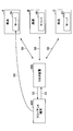
- FIG. 1 shows an example of the overall configuration of the system according to the embodiment of the present invention.
- the system includes a load control device 100 and a GSLB device 200, which can communicate via the network 300.
- a GSLB device 200 which can communicate via the network 300.
- Each base is equipped with one or more servers, and the one or more servers provide services to a large number of client terminals.
- the service is, for example, online shopping site provision, video distribution, cloud infrastructure provision, etc., but is not limited to these.
- a system consisting of these plurality of servers may be called a service providing system.
- a system consisting of a plurality of bases equipped with a server may be called a service providing system.
- Each base is assumed to be a building such as a communication building or a data center, but such an assumption is an example.
- a “base” may be in a narrower range than a building (eg, 1 floor, 1 room, etc.), and a “base” may be in a wider range than a building (eg, a group of buildings, a town, a city, etc.). , Prefecture, region, etc.).
- the load control device 100 moves the load of the server between the bases based on the target power value of each base based on the DR request at each base and the amount of power generation (solar radiation amount, etc.), thereby consuming the power of each base. Controls the power consumption so that it approaches the target power value.
- the load control device may be referred to as a power consumption control device or a control device.
- the GSLB device 200 is used as an example of the means for moving the load of the server between the bases.
- this is not the only means of moving the load on the server between bases.
- live migration can be used as a means of moving the load of the server between bases.
- the "GSLB device 200" is not limited to a device physically composed of one device, but may be a system composed of a plurality of devices.
- a connection request (eg, an HTTP request, hereinafter referred to as a request) from a client terminal 400 is distributed by the GSLB device 200 to any of the servers 2A, server 2B, and server 2C.
- the GSLB device 200 periodically performs a health check of each server. For example, when a failed server is detected, the server is prevented from accessing the server.
- weighting such as 3: 2: 1 is set for the three distribution destinations of the server 2A, the server 2B, and the server 2C as setting parameters.
- 3/6 is connected to Server 2A
- 2/6 is connected to Server 2B
- 1/6 is Server. Connected to 2C.
- the client terminal 400 sends a DNS request specifying the domain name of the service to the GSLB device 200.
- the GSLB device 200 returns, for example, the IP address of the server 2A to the client terminal 400 based on the above weights.
- the client terminal 400 transmits a request to the server 2A.
- the base A is provided with the redundant server 2A-1 and the server 2A-2
- the base B is provided with the redundant server 2B-1 and the server 2B-2.
- the GSLB device 200-1 executes load balancing control for the server 2A-1 and the server 2B-1
- the GSLB device 200-2 executes the load balancing control for the server 2A-2 and the server 2B-2.
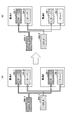
- FIG. 3A shows a normal state, and in this case, it is assumed that the GSLB devices 200-1 and 200-2 are operating so that requests are distributed between the bases A and the base B by 50% each. do.
- the load control device 100 changes the settings of the GSLB devices 200-1 and 200-2 to the servers 2A-1 and 2A-2.
- the distribution ratio is increased, and the distribution ratio to the servers 2B-1 and 2B-2 is decreased. That is, the load is moved to the servers 2A-1 and 2A-2 to reduce the load on the servers 2B-1 and 2B-2.
- the power consumption of the base B can be reduced.
- requests for increase / decrease in power consumption at each base for example, requests for improving the utilization rate of renewable energy, requests for responding to requests for increased / decreased DR from electric power companies, and dynamic pricing have been realized. It is assumed that there will be demands related to the minimization of the electricity purchase price.
- the weather is good at a base equipped with a solar power generation device, and a large amount of power can be obtained by solar power generation.
- the grid can be made to follow the renewable energy output under unstable renewable energy output such as solar power generation and wind power generation. It also includes stabilizing.
- Minimizing the power purchase price when dynamic pricing is realized means that when the power charge changes according to geographical division, time zone, etc., for example, the power consumption of a base with a low power charge becomes high. It is to control the load of the server so that the power consumption of the base where the power charge is high is low.
- the response speed will be slightly slower, but it is possible to cause a larger increase or decrease in energy.
- FIG. 4 shows a configuration example of the base A in the present embodiment.
- FIG. 4 shows the base A as an example, but other bases have the same configuration. However, there may be a base that does not have the power generation unit 1.
- the base A is a power distribution unit 3A connected to a power generation unit 1A that generates power with renewable energy such as solar energy, a server 2A that provides services, and a distribution network 10A provided by an electric power company or the like. It has ancillary equipment 4A such as air conditioning and lighting of a server room, and a monitoring control device 5A.
- server 2A may be physically one server or a server group composed of a plurality of servers. Further, the “server 2A” may be a virtual function such as a container. However, even a virtual function such as a container actually operates on a computer (physical server) that consumes power.
- a server is shown as a device for providing services in FIG. 4, a communication device such as a router or a switch is provided in addition to the server, and the communication device also has power consumption control according to the present embodiment. It may be a target. Further, it may be assumed that the communication device is also realized by the server. Servers and communication devices may be collectively referred to as consumer devices.
- the distribution unit 3A supplies the power received from the distribution network 10 to the server 2A and the ancillary equipment 4A. However, when the power generation unit 1A is sufficiently generating power (when the voltage is high), the power supply to the server 2A is performed by the power generation unit 1A. Further, the distribution unit 3A can also transfer the surplus electric power among the electric power generated by the power generation unit 1A to another base, if necessary.
- the monitoring and control device 5A can perform control communication with each part by the communication network in the base. Further, the monitoring control device 5A is connected to the load control device 100 via the network 300.
- the monitoring control device 5A can acquire the load (eg, the number of requests, the number of simultaneous connections, the CPU usage rate, the memory usage rate, etc.) in the server 2A from the server 2A and notify the load control device 100 of it. ..
- the monitoring control device 5A can control the ancillary equipment 4A based on, for example, a command from the load control device 100. Controls include, for example, lighting ON / OFF, air conditioning temperature setting change, and the like.
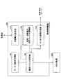
- FIG. 5 shows a configuration example of the load control device 100.
- the load control device 100 includes a target power setting unit 110, a service load prediction unit 120, a load balance setting unit 130, a load-power consumption correspondence table storage unit 140, and a service load measurement unit 150. The operation of each part will be described later.
- the load control device 100 may be physically one device (computer) or a system composed of a plurality of devices.
- the load control device 100 can be realized by, for example, causing a computer to execute a program describing the processing contents described in the present embodiment.
- the "computer” may be a physical machine or a virtual machine on the cloud.
- the "hardware” described here is virtual hardware.
- the above program can be recorded on a computer-readable recording medium (portable memory, etc.), saved, and distributed. It is also possible to provide the above program through a network such as the Internet or e-mail.
- FIG. 6 is a diagram showing an example of the hardware configuration of the above computer.
- the computer of FIG. 6 has a drive device 1000, an auxiliary storage device 1002, a memory device 1003, a CPU 1004, an interface device 1005, a display device 1006, an input device 1007, an output device 1008, and the like, which are connected to each other by a bus BS, respectively.
- the program that realizes the processing on the computer is provided by, for example, a recording medium 1001 such as a CD-ROM or a memory card.
- a recording medium 1001 such as a CD-ROM or a memory card.
- the program is installed in the auxiliary storage device 1002 from the recording medium 1001 via the drive device 1000.
- the program does not necessarily have to be installed from the recording medium 1001, and may be downloaded from another computer via the network.
- the auxiliary storage device 1002 stores the installed program and also stores necessary files, data, and the like.
- the memory device 1003 reads and stores the program from the auxiliary storage device 1002 when there is an instruction to start the program.
- the CPU 1004 realizes the function related to the load control device 100 according to the program stored in the memory device 1003.
- the interface device 1005 is used as an interface for connecting to a network.
- the display device 1006 displays a GUI (Graphical User Interface) or the like by a program.
- the input device 1007 is composed of a keyboard, a mouse, buttons, a touch panel, and the like, and is used for inputting various operation instructions.
- the output device 1008 outputs the calculation result.
- the service load prediction unit 120 predicts the future load of the service from information such as the past load of the target service. More specifically, the service load prediction unit 120 predicts the number of requests per unit time for the target service at a certain time t in the future.
- the service load prediction unit 120 may use the server 2A and the server at a certain time t in the future. Predict the number of requests per unit time to 2B and server 2C.
- the time t is the time obtained by adding T seconds to the current time. Is.
- the time t is not limited to this.
- the load prediction method is not limited to a specific method, but the load can be predicted by using, for example, an ARIMA model or a regression analysis.
- the target power setting unit 110 sets (determines) a target power value (target power consumption) for each base at time t, and notifies the load balance setting unit 130 of the target power value.
- the target power setting unit 110 is the base A, the base B, and the base C, respectively.
- Set the target power value It is not essential to set the target power value of all the bases equipped with the server that provides the target service.
- the target power value may be set only for the bases that need to increase or decrease the power consumption. An example of what kind of value is set as the "target power value" will be described below.
- the target power setting unit 110 periodically performs power consumption of each current consumable device (server, ancillary equipment, etc.) at each base, DR request from the power company, and dynamic pricing from the monitoring control device 5 at each base.
- a current consumable device server, ancillary equipment, etc.
- DR request from the power company
- dynamic pricing from the monitoring control device 5 at each base.
- the target power setting unit 110 sets the target power value to 450 kW based on the lower DR request to the base A. Further, the target power setting unit 110 knows that the amount of power generated at the base B in fine weather is 50 kW, and determines the target power value to be 550 kW. For base C, the target power value will be 500 kW without any change. Regarding the target power value setting in such a form, since the service load prediction is not considered at this point, the actual power consumption after the load balance setting may be different from the target power value.
- the target power value is set so that the power consumption of the base with the low power charge becomes high, that is, the power charge approaches the lowest as a whole. May be set.
- the power consumption of all the bases A to C that provide the target service is set to 100% so that the power consumption at the base C is high.
- an increase / decrease value such as reducing the power consumption by 20 kW for the base A or increasing the power consumption by 20 kW for the base B may be set as the target power value.
- the target power consumption (kWh) for each base may be set as the target power value.
- the target power setting unit 110 notifies the load balance setting unit 130 of the target power value set as described above.
- the load balance setting unit 130 includes the predicted load of the service at the time t predicted by the service prediction load unit 120, the target power value set by the target power setting unit 110, and the load-power consumption correspondence table storage unit. Based on the load-power consumption correspondence table stored in 140 and the information from the service load measurement unit 150, the parameters (load balance) to be set in the GSLB device 200 are calculated, and the calculated parameters are used in the GSLB device 200. Set to.
- the load-power consumption correspondence table for example, as shown in FIG. 8, correspondence information between the load (example: the number of requests to the server per unit time) and the power consumption of the server is recorded.
- the load may be, for example, a CPU usage rate or the like.
- the service load measuring unit 150 measures the load for each server (eg, the number of requests per unit time) and notifies the load balance setting unit 130 of the load.
- the load balance setting unit 130 needs to reduce the load of the base A (server 2A) from 60 to 20 in order to reduce the power consumption of the base A by 20 kW by referring to the load-power consumption correspondence table. It is determined that the load of the base B (server 2B) needs to be increased from 60 to 100 in order to increase the power consumption of the base B by 20 kW.
- the GSLB device 200 that has received the setting executes the distribution of requests according to the setting.
- any or all of the service load forecast values, the load-power consumption correspondence table, and the current service load values may not be used. That is, any one or all of the service load prediction unit 120, the load-power consumption correspondence table storage unit 140, and the service load measurement unit 150 may not be provided.
- the GSLB device 200 is used to transfer the load between the servers in the form of request distribution control, but the method of load transfer is not limited to this.
- the load balance setting unit 130 instructs the server 2A and the server 2B to move the virtual machine operating on the server 2A by live migration. It may be moved to the server 2B.
- the load control is performed only for the server, but the power control for the auxiliary equipment 4 (air conditioning, lighting, etc.) may be performed in addition to the control for the server.
- the load balance setting unit 130 monitors the base A.
- the control device 5A is instructed to raise the set temperature of the air conditioner in the server room by a predetermined range (for example, 1 ° C.).
- the monitoring control device 5A may automatically control the air conditioning according to the instruction, or the operator may manually control the air conditioning by looking at the instruction displayed on the monitoring control device 5A.
- the business operator can control the server load of the user by utilizing the GSLB device, thereby controlling the energy consumption, generating negative / positive watts, and controlling the renewable energy utilization rate. It can be maximized.
- This specification describes at least the control devices, control methods, and programs described in the following items.
- (Section 1) It is a control device that controls the power consumption in a service providing system that provides services by servers provided in each of multiple geographically dispersed bases.
- a target power setting unit that sets a target power value for the site based on a request for an increase or decrease in power consumption at the site provided with the server.
- a control device including a load balance setting unit that moves a load between a plurality of servers based on the target power value.
- the load balance setting unit performs load transfer by setting a distribution weight for a wide area load distribution device that controls distribution of requests in the service providing system.
- a control method including a load balance setting step for transferring a load between a plurality of servers based on the target power value.
- (Section 6) A program for causing a computer to function as each part in the control device according to any one of the items 1 to 4.
Landscapes
- Engineering & Computer Science (AREA)
- Power Engineering (AREA)
- Theoretical Computer Science (AREA)
- Physics & Mathematics (AREA)
- General Engineering & Computer Science (AREA)
- General Physics & Mathematics (AREA)
- Remote Monitoring And Control Of Power-Distribution Networks (AREA)
- Supply And Distribution Of Alternating Current (AREA)
- Power Sources (AREA)
Abstract
地理的に分散して配置された複数拠点のそれぞれに備えられたサーバによりサービスを提供するサービス提供システムにおける消費電力を制御する制御装置であって、前記サーバが備えられた拠点における消費電力の増減に関する要求に基づいて、当該拠点の目標電力値を設定する目標電力設定部と、前記目標電力値に基づいて、複数のサーバ間での負荷移動を行う負荷バランス設定部とを備える。
Description
本発明は、複数拠点のサーバ間で負荷移動を行う技術に関連するものである。
複数のサーバを用いてWebサイトを構築し、ロードバランサ(以下LB)でリクエストを複数のサーバに振り分けることが従来から行われている。これにより、能力不足時の拡張を容易にしたり(拡張性)、一部のサーバが故障した時のサービス全体の停止を防いだり(可用性)することができる。
また、複数の拠点間でLBの機能を実現する広域負荷分散(GSLB:Global Server Load Balancing)も使用されている。
一方、データセンタや通信ビル等の拠点においては、配電網を介して商用電源から電力を受電し、サーバ等に電力を供給することに加えて、太陽光発電(PV:Photovoltaic)等の再生可能エネルギーによる発電部を備え、発電部で発電された電力を利用することも行われてきている。
なお、非特許文献1には、分散型Webサーバにおいて、QoSを制約条件として電力の最適化を行うことが開示されている。
「分散型Webサーバでの負荷変動を考慮した省電力化のためのノード状態制御」、情報処理学会論文誌 コンピューティングシステム, vol.2, No.2, 75-88, July, 2009.
将来設置される電力の需給調整市場においては、大規模な電力の増減を迅速に行うことを可能とするVPP(Virtual Power Plant)が求められているが、従来技術では、規模・応答速度ともにそれらに対応することは難しい。また、今後、更に安価になり大量導入が予測される出力の不安定な再生可能エネルギーを自家消費するために、発電量に合わせた電力消費をすることも求められてくる。
本発明は上記の点に鑑みてなされたものであり、複数拠点に備えられたサーバによりサービスを提供するサービス提供システムにおいて、消費電力の増減に関する要求に応じて迅速に消費電力の増減の制御を行うことを可能とする技術を提供することを目的とする。
開示の技術によれば、地理的に分散して配置された複数拠点のそれぞれに備えられたサーバによりサービスを提供するサービス提供システムにおける消費電力を制御する制御装置であって、
前記サーバが備えられた拠点における消費電力の増減に関する要求に基づいて、当該拠点の目標電力値を設定する目標電力設定部と、
前記目標電力値に基づいて、複数のサーバ間での負荷移動を行う負荷バランス設定部と
を備える制御装置が提供される。
前記サーバが備えられた拠点における消費電力の増減に関する要求に基づいて、当該拠点の目標電力値を設定する目標電力設定部と、
前記目標電力値に基づいて、複数のサーバ間での負荷移動を行う負荷バランス設定部と
を備える制御装置が提供される。
開示の技術によれば、複数拠点に備えられたサーバによりサービスを提供するサービス提供システムにおいて、消費電力の増減に関する要求に応じて迅速に消費電力の増減の制御を行うことを可能とする技術が提供される。
以下、図面を参照して本発明の実施の形態(本実施の形態)を説明する。以下で説明する実施の形態は一例に過ぎず、本発明が適用される実施の形態は、以下の実施の形態に限られるわけではない。
(システム構成)
図1に、本発明の実施の形態におけるシステムの全体構成例を示す。図1に示すように、本システムには、負荷制御装置100とGSLB装置200が備えられ、これらはネットワーク300を介して通信可能である。また、地理的に分散して配置された複数の拠点(図1の例では拠点A~Z)が存在し、拠点内のサーバ等がネットワーク300を介して負荷制御装置100と通信可能である。
図1に、本発明の実施の形態におけるシステムの全体構成例を示す。図1に示すように、本システムには、負荷制御装置100とGSLB装置200が備えられ、これらはネットワーク300を介して通信可能である。また、地理的に分散して配置された複数の拠点(図1の例では拠点A~Z)が存在し、拠点内のサーバ等がネットワーク300を介して負荷制御装置100と通信可能である。
各拠点は、1以上のサーバを備え、当該1以上のサーバは多数のクライアント端末にサービスを提供する。当該サービスは、例えばオンラインショッピングサイト提供、映像配信、クラウド基盤提供等であるが、これらに限られない。これらの複数サーバからなるシステムをサービス提供システムと呼んでもよい。また、サーバを備えた複数拠点からなるシステムをサービス提供システムと呼んでもよい。
各拠点は、通信ビルやデータセンタ等の建物であることを想定しているが、そのような想定は一例である。「拠点」は、建物よりも狭い範囲のもの(例:1フロア、1部屋等)であってもよいし、「拠点」は、建物よりも広い範囲のもの(例:建物群、町、市、県、地域等)であってもよい。
負荷制御装置100は、各拠点におけるDR要請や発電量(日射量等)等に基づく各拠点の目標電力値等に基づいて、拠点間でサーバの負荷を移動させることにより、各拠点の消費電力が目標電力値に近づくように、消費電力の制御を行う。なお、負荷制御装置を、消費電力制御装置あるいは制御装置と呼んでもよい。
本実施の形態では、拠点間でサーバの負荷を移動させる手段の例として、GSLB装置200を使用する。ただし、拠点間でサーバの負荷を移動させる手段はこれに限られるわけではない。例えば、拠点間でサーバの負荷を移動させる手段として、ライブマイグレーションを用いることも可能である。
(動作概要)
まず、拠点間でサーバの負荷を移動させる手段としてのGSLB装置200の動作の概要を、図2を参照して説明する。なお、「GSLB装置200」は、物理的に1つの装置からなるものに限らず、複数装置からなるシステムであってもよい。
まず、拠点間でサーバの負荷を移動させる手段としてのGSLB装置200の動作の概要を、図2を参照して説明する。なお、「GSLB装置200」は、物理的に1つの装置からなるものに限らず、複数装置からなるシステムであってもよい。
図2に示す例では、地理的に分散して配置された拠点A~Cが存在し、各拠点にはサーバ2(サーバ2A、サーバ2B、サーバ2C)が存在する。GSLB装置200によりクライアント端末400からの接続リクエスト(例:HTTPリクエスト、以下、リクエストと呼ぶ)が、サーバ2A、サーバ2B、サーバ2Cのうちのいずれかのサーバに振り分けられる例を説明する。
S0(ステップ0)において、GSLB装置200は、定期的に各サーバのヘルスチェックを行っており、例えば故障したサーバを検知したら、当該サーバへのアクセスをさせないようにする。
また、GSLB装置200には、設定パラメータとして、サーバ2A、サーバ2B、サーバ2Cの3つの振り分け先に対して、例えば3:2:1といった重み付けが設定されている。この場合、「サーバ2A、サーバ2B、サーバ2C」により提供されるサービスへの全アクセスのうち、3/6がサーバ2Aに接続され、2/6がサーバ2Bに接続され、1/6がサーバ2Cに接続される。
S1において、クライアント端末400が、サービスのドメイン名を指定したDNSリクエストをGSLB装置200に送信する。S2において、GSLB装置200は上記の重みに基づいて、例えば、サーバ2AのIPアドレスをクライアント端末400に返す。この場合、S3において、クライアント端末400は、サーバ2Aに対してリクエストを送信する。
実際には、多くのクライアント端末が存在し、各クライアント端末からのリクエストがサーバ2A、サーバ2B、サーバ2Cのいずれかに振り分けられることで、上記重みに基づいた拠点間での負荷分散が実現される。
図3を参照して、本実施の形態における負荷分散制御100により実現される、拠点Aと拠点Bとの間での消費電力制御の例を説明する。
図3に示す例では、拠点Aに冗長化されたサーバ2A-1とサーバ2A-2が備えられ、拠点Bに冗長化されたサーバ2B-1とサーバ2B-2が備えられている。また、GSLB装置200-1が、サーバ2A-1とサーバ2B-1に対する負荷分散制御を実行し、GSLB装置200-2が、サーバ2A-2とサーバ2B-2に対する負荷分散制御を実行する。
図3の(a)は、通常状態を示しており、この場合、拠点Aと拠点B間でリクエストが50%ずつで振り分けられるようにGSLB装置200-1、200-2が動作しているとする。
その後、拠点Bにおいて、消費電力を減少させる要求があったとすると、負荷制御装置100は、GSLB装置200-1、200-2の設定変更を行うことで、サーバ2A-1、2A-2への振り分けの割合を増加させ、サーバ2B-1、2B-2への振り分けの割合を減少させる。つまり、サーバ2A-1、2A-2に負荷を移動させて、サーバ2B-1、2B-2の負荷を下げる。これにより、拠点Bの消費電力を下げることができる。
各拠点における消費電力の増減の要求としては、例えば、再生可能エネルギーの利用率の向上に関わる要求、電力会社からの上げDR要請/下げDR要請への対応に関わる要求、ダイナミックプライシングが実現された際の電力購入価格の最小化に関わる要求、等が想定される。
再生可能エネルギーの利用率の向上に関わる要求として、例えば、太陽光発電装置を備える拠点において天気がよく、太陽光発電により大きな電力が得られるので、それを有効に利用するために、当該拠点のサーバの消費電力を増加させる要求がある。また、再生可能エネルギーの利用率の向上に関わる要求には、太陽光発電や風力発電等の不安定な再生可能エネルギー出力の下で、電力需要を再生可能エネルギー出力に追従させることで、系統を安定化させることも含まれる。
ダイナミックプライシングが実現された際の電力購入価格の最小化とは、地理的区分毎、時間帯毎等に応じて電力料金が変化する場合において、例えば、電力料金の安い拠点の消費電力が高くなり、電力料金の高い拠点の消費電力が低くなるようにサーバの負荷を制御することである。
サーバの負荷と消費電力には正の相関があることから、GSLB装置200を活用して特定のサーバの負荷を制御することで、結果的に消費電力を制御することができる。また、制御を迅速に行うことができる。
更に、拠点における空調やサーバルームの照明等の付随設備も併せて制御することで、応答速度はやや遅くなるものの、より大規模なエネルギー増減を引き起こすことも可能である。
以下、本システムの構成と動作をより詳細に説明する。
(拠点の構成例)
図4に、本実施の形態における拠点Aの構成例を示す。図4は例として拠点Aを示しているが、他の拠点も同様の構成を備える。ただし、発電部1を備えない拠点が存在してもよい。
図4に、本実施の形態における拠点Aの構成例を示す。図4は例として拠点Aを示しているが、他の拠点も同様の構成を備える。ただし、発電部1を備えない拠点が存在してもよい。
図4に示すように、拠点Aは、太陽光等の再生可能エネルギーで発電を行う発電部1A、サービスを提供するサーバ2A、電力会社等により提供される配電網10Aと接続される配電部3A、空調やサーバルームの照明等の付随設備4A、及び監視制御装置5Aを有する。
なお、「サーバ2A」は、物理的に1つのサーバであってもよいし、複数サーバからなるサーバ群であってもよい。また、「サーバ2A」が、コンテナのような仮想的な機能であってもよい。ただし、コンテナのような仮想的な機能であっても、実際には電力を消費するコンピュータ(物理サーバ)上で動作する。
なお、図4には、サービス提供のための装置としてサーバが示されているが、サーバに加えてルータ、スイッチ等の通信装置が備えられ、通信装置についても本実施の形態における消費電力制御の対象であってもよい。また、通信装置も、サーバにより実現されると想定してもよい。サーバや通信装置を総称して消費機器と称してもよい。
配電部3Aは、配電網10から受電した電力をサーバ2A及び付随設備4Aに給電する。ただし、発電部1Aが十分に発電をしているとき(電圧が高いとき)には、サーバ2Aへの給電は発電部1Aにより行われる。また、配電部3Aは、必要に応じて、発電部1Aが生成した電力のうち、余った電力を他拠点に融通することも可能である。
監視制御装置5Aは、拠点内通信網により、各部と制御通信を行うことが可能である。また、監視制御装置5Aは、ネットワーク300を介して負荷制御装置100と接続される。
例えば、監視制御装置5Aは、サーバ2Aにおける負荷(例:リクエスト数、同時接続数、CPU使用率、メモリ使用率等)をサーバ2Aから取得し、それを負荷制御装置100に通知することができる。
また、監視制御装置5Aは、例えば負荷制御装置100からの命令に基づいて、付随設備4Aを制御することができる。制御としては、例えば、照明のON/OFF、空調の温度設定変更等がある。
(負荷制御装置の構成例)
図5に、負荷制御装置100の構成例を示す。図5に示すように、負荷制御装置100は、目標電力設定部110、サービス負荷予測部120、負荷バランス設定部130、負荷―消費電力対応テーブル格納部140、サービス負荷計測部150を備える。各部の動作については後述する。負荷制御装置100は、物理的に1つの装置(コンピュータ)であってもよいし、複数の装置から構成されるシステムであってもよい。
図5に、負荷制御装置100の構成例を示す。図5に示すように、負荷制御装置100は、目標電力設定部110、サービス負荷予測部120、負荷バランス設定部130、負荷―消費電力対応テーブル格納部140、サービス負荷計測部150を備える。各部の動作については後述する。負荷制御装置100は、物理的に1つの装置(コンピュータ)であってもよいし、複数の装置から構成されるシステムであってもよい。
<ハードウェア構成例>
本実施の形態における負荷制御装置100は、例えば、コンピュータに、本実施の形態で説明する処理内容を記述したプログラムを実行させることにより実現可能である。なお、この「コンピュータ」は、物理マシンであってもよいし、クラウド上の仮想マシンであってもよい。仮想マシンを使用する場合、ここで説明する「ハードウェア」は仮想的なハードウェアである。
本実施の形態における負荷制御装置100は、例えば、コンピュータに、本実施の形態で説明する処理内容を記述したプログラムを実行させることにより実現可能である。なお、この「コンピュータ」は、物理マシンであってもよいし、クラウド上の仮想マシンであってもよい。仮想マシンを使用する場合、ここで説明する「ハードウェア」は仮想的なハードウェアである。
上記プログラムは、コンピュータが読み取り可能な記録媒体(可搬メモリ等)に記録して、保存したり、配布したりすることが可能である。また、上記プログラムをインターネットや電子メール等、ネットワークを通して提供することも可能である。
図6は、上記コンピュータのハードウェア構成例を示す図である。図6のコンピュータは、それぞれバスBSで相互に接続されているドライブ装置1000、補助記憶装置1002、メモリ装置1003、CPU1004、インタフェース装置1005、表示装置1006、入力装置1007、出力装置1008等を有する。
当該コンピュータでの処理を実現するプログラムは、例えば、CD-ROM又はメモリカード等の記録媒体1001によって提供される。プログラムを記憶した記録媒体1001がドライブ装置1000にセットされると、プログラムが記録媒体1001からドライブ装置1000を介して補助記憶装置1002にインストールされる。但し、プログラムのインストールは必ずしも記録媒体1001より行う必要はなく、ネットワークを介して他のコンピュータよりダウンロードするようにしてもよい。補助記憶装置1002は、インストールされたプログラムを格納すると共に、必要なファイルやデータ等を格納する。
メモリ装置1003は、プログラムの起動指示があった場合に、補助記憶装置1002からプログラムを読み出して格納する。CPU1004は、メモリ装置1003に格納されたプログラムに従って、負荷制御装置100に係る機能を実現する。インタフェース装置1005は、ネットワークに接続するためのインタフェースとして用いられる。表示装置1006はプログラムによるGUI(Graphical User Interface)等を表示する。入力装置1007はキーボード及びマウス、ボタン、又はタッチパネル等で構成され、様々な操作指示を入力させるために用いられる。出力装置1008は演算結果を出力する。
(負荷制御装置の動作例)
次に、図7に示すフローチャートの手順に沿って、負荷制御装置100の動作例を説明する。以下では、対象とするサービスが、拠点Aのサーバ2A、拠点Bのサーバ2B、拠点Cのサーバ2Cにより提供される場合を例にとって説明する。
次に、図7に示すフローチャートの手順に沿って、負荷制御装置100の動作例を説明する。以下では、対象とするサービスが、拠点Aのサーバ2A、拠点Bのサーバ2B、拠点Cのサーバ2Cにより提供される場合を例にとって説明する。
<S101>
S101において、サービス負荷予測部120は、対象とするサービスの過去の負荷等の情報から当該サービスの将来の負荷を予測する。より具体的には、サービス負荷予測部120は、将来のある時刻tにおける対象とするサービスへの単位時間当たりのリクエスト数を予測する。
S101において、サービス負荷予測部120は、対象とするサービスの過去の負荷等の情報から当該サービスの将来の負荷を予測する。より具体的には、サービス負荷予測部120は、将来のある時刻tにおける対象とするサービスへの単位時間当たりのリクエスト数を予測する。
例えば、対象とするサービスが、拠点Aのサーバ2A、拠点Bのサーバ2B、拠点Cのサーバ2Cにより提供される場合において、サービス負荷予測部120は、将来のある時刻tにおける、サーバ2A、サーバ2B、及びサーバ2Cへの単位時間当たりのリクエスト数を予測する。
現在時刻から、S101~S103の制御により、各拠点のサーバの負荷(リクエスト数)の移動が完了するまでの時間がT秒であるとすると、時刻tは、現在時刻にT秒を加えた時刻である。ただし、時刻tはこれに限られない。
なお、負荷としてリクエスト数を用いることは一例である。例えば、同時接続ユーザ数、サービスに係るサーバ全体のCPU使用率等を負荷として使用することとしてもよい。また、負荷の予測方法は特定の方法に限られないが、例えば、ARIMAモデルや回帰分析等を用いて負荷の予測を行うことができる。
<S102>
S102において、目標電力設定部110は、時刻tにおける拠点毎の目標電力値(目標となる消費電力)を設定(決定)し、当該目標電力値を負荷バランス設定部130に通知する。
S102において、目標電力設定部110は、時刻tにおける拠点毎の目標電力値(目標となる消費電力)を設定(決定)し、当該目標電力値を負荷バランス設定部130に通知する。
例えば、対象とするサービスが、拠点Aのサーバ2A、拠点Bのサーバ2B、拠点Cのサーバ2Cにより提供される場合において、目標電力設定部110は、拠点A、拠点B、及び拠点Cそれぞれの目標電力値を設定する。なお、対象とするサービスを提供するサーバを備える全ての拠点の目標電力値を設定することは必須ではない。例えば、消費電力の上げ又は下げを要する拠点のみの目標電力値を設定することとしてもよい。どのような値を「目標電力値」とするかについては、下記で例を説明する。
目標電力設定部110は、例えば定期的に、各拠点の監視制御装置5から、各拠点における、現在の各消費機器(サーバ、付随設備等)の消費電力、電力会社からのDR要請、ダイナミックプライシングが実現された際の電力料金、再生可能エネルギーについての状況(天気、風力等)等の情報を収集している。現在のこれらの情報から、時刻tでの情報は推定可能である。
目標電力設定部110は、上記の情報を用いて、時刻tにおける拠点毎の目標電力値を設定する。例えば、対象とするサービスが、拠点Aのサーバ2A、拠点Bのサーバ2B、拠点Cのサーバ2Cにより提供される場合において、目標電力設定部110が、拠点Aにおいて50kWの下げDR要請があり、発電部1Bとして太陽光発電設備を持つ拠点Bにおいて、天気の悪い状態から晴天になったことを検知したとする。また、現在の消費電力(拠点内全体の消費電力の合計)が拠点A=500kW、拠点B=500kW、拠点C=500kWであるとする。
目標電力設定部110は、拠点Aに対し、下げDR要請に基づき、目標電力値を450kWと設定する。また、目標電力設定部110は、拠点Bにおける晴天時の発電量が50kWであることを把握しており、目標電力値を550kWと決定する。拠点Cについては変更なく500kWを目標電力値とする。このような形での目標電力値設定に関して、この時点では、サービス負荷予測を考慮していないので、負荷バランス設定後の実際の消費電力は目標電力値と異なり得る。
また、例えば、時刻tの時間帯における電力料金が拠点間で異なる場合において、電力料金の安い拠点の消費電力が高くなるように、つまり、全体として電力料金が最安に近づくように目標電力値を設定してもよい。例えば、電力料金が、「拠点A=拠点B>拠点C」である場合に、拠点Cでの消費電力が高くなるように、対象サービスを提供する拠点A~C全体の消費電力を100%としたときに、「拠点A=30%、拠点B=30%、拠点C=40%」という形で目標電力値を設定してもよい。
また、目標電力値の設定を「大小」のような曖昧な情報で設定してもよい。例えば、上記の状況(拠点A=下げDR要請、拠点B=晴天になった)においては、拠点Aに対して「小」(消費電力を小さくする)、拠点Bに対して「大」(消費電力を大きくする)を目標電力値として設定してもよい。
また、例えば、拠点Aに対して消費電力を20kW減らす、拠点Bに対して消費電力を20kW増加させる、といった増減値を目標電力値として設定してもよい。また、拠点毎の目標とする消費電力量(kWh)を目標電力値として設定してもよい。
目標電力設定部110は、上記にようにして設定した目標電力値を負荷バランス設定部130に通知する。
<S103>
S103において、負荷バランス設定部130は、サービス予測負荷部120により予測された時刻tのサービスの予測負荷と、目標電力設定部110により設定された目標電力値と、負荷‐消費電力対応テーブル格納部140に格納されている負荷‐消費電力対応テーブルと、サービス負荷計測部150からの情報とに基づいて、GSLB装置200に設定すべきパラメータ(負荷バランス)を算出し、算出したパラメータをGSLB装置200に設定する。
S103において、負荷バランス設定部130は、サービス予測負荷部120により予測された時刻tのサービスの予測負荷と、目標電力設定部110により設定された目標電力値と、負荷‐消費電力対応テーブル格納部140に格納されている負荷‐消費電力対応テーブルと、サービス負荷計測部150からの情報とに基づいて、GSLB装置200に設定すべきパラメータ(負荷バランス)を算出し、算出したパラメータをGSLB装置200に設定する。
負荷‐消費電力対応テーブルには、例えば図8に示すように、負荷(例:サーバへの単位時間当たりのリクエスト数)とサーバの消費電力との対応情報が記録されている。なお、負荷は、例えばCPU使用率等であってもよい。また、サービス負荷計測部150は、サーバ毎の負荷(例:単位時間当たりのリクエスト数)を計測し、それを負荷バランス設定部130に通知している。
例えば、負荷バランス設定部130は、拠点Aに対して消費電力を20kW減らす、拠点Bに対して消費電力を20kW増加させるという目標電力値を目標電力設定部110から受信し、また、時刻tのサービス負荷として、「200」をサービス負荷予測部120から受信したとする。また、サービス負荷計測部150から受信した現在の負荷が「拠点Aのサーバ2A=60、拠点Bのサーバ2B=60、拠点Cのサーバ2C=60」であるとする。
この場合、負荷バランス設定部130は、負荷‐消費電力対応テーブルを参照することにより、拠点Aの消費電力を20kW減らすために、拠点A(サーバ2A)の負荷を60から20にする必要があると判断し、拠点Bの消費電力を20kW増加させるために、拠点B(サーバ2B)の負荷を60から100にする必要があると判断する。
また、サービス全体の負荷予測が200なので、負荷バランス設定部130は、拠点C(サーバ2C)の負荷を200-20-100=80にする必要があると判断する。つまり、拠点A、B、Cのリクエスト数の比率は、拠点A:拠点B:拠点C=20:100:80=1:5:4になる。
よって、負荷バランス設定部130は、GSLB装置200に設定するパラメータ(リスエスト数の重み)として、「拠点A:拠点B:拠点C=1:5:4」を算出し、これをGSLB装置200に設定する。設定を受けたGSLB装置200は、設定に従ってリクエストの振り分けを実行する。
なお、サービス負荷予測の値、負荷‐消費電力対応テーブル、及び現在のサービス負荷の値のうちのいずれか又は全部を使用しないこととしてもよい。つまり、サービス負荷予測部120、負荷‐消費電力対応テーブル格納部140、サービス負荷計測部150のうちのいずれか又は全部を備えないこととしてもよい。
サービス負荷予測の値、負荷‐消費電力対応テーブル、及び現在のサービス負荷の値を使用しない場合において、例えば、負荷バランス設定部130は、拠点Aに対して「小」(消費電力を小さくする)、拠点Bに対して「大」(消費電力を大きくする)を目標電力値として設定されたとすると、GSLB装置200に設定するパラメータの値をある決められた値だけ変更する。例えば、変更前の重みが「拠点A:拠点B:拠点C=3:3:4」であるとした場合に、変更後の重みを「拠点A:拠点B:拠点C=2:4:4」とする。
また、負荷バランス設定部130に対象サービスのサービス要件(SLA、SLO等)を入力し、負荷バランス設定部130は、サービス要件を制約として使用して、GSLB装置200に設定するパラメータを算出してもよい。例えば、サービス要件の制約を用いない場合において、重みが「拠点A:拠点B:拠点C=0:2:3」になる場合において、サービス要件により、可用性あるいは信頼性の観点で少なくとも拠点Aと拠点Bを振り分け先に含めなければならない場合には、負荷バランス設定部130は、重みを例えば「拠点A:拠点B:拠点C=1:1:3」とする。
なお、上記の例では、GSLB装置200により、リクエストの振り分け制御の形でサーバ間での負荷移動を行うこととしているが、負荷移動の方法はこれに限られるわけではない。例えば、サーバ2Aの負荷をサーバ2Bに移動させたい場合において、負荷バランス設定部130は、サーバ2Aとサーバ2Bに対して指示することで、サーバ2A上で動作する仮想マシンを、ライブマイグレーションにより、サーバ2Bに移動させることとしてもよい。
また、上記の例ではサーバのみについての負荷制御を行うこととしているが、サーバへの制御と合わせて付随設備4(空調、照明等)に対する電力制御を行うこととしてもよい。
例えば、拠点Aに対して、下げDR要請があったが、サーバ2Aの負荷制御のみでは下げDR要請に応える十分な消費電力の削減ができない場合において、負荷バランス設定部130は、拠点Aの監視制御装置5Aに対して、例えば、サーバルームの空調の設定温度を所定幅(例えば1℃)上げるように指示する。監視制御装置5Aは指示に従って自動的に空調を制御してもよいし、作業者が監視制御装置5Aに表示される指示を見て、手動で空調を制御してもよい。
(実施の形態の効果)
本実施の形態に係る技術によれば、複数拠点に備えられたサーバによりサービスを提供するサービス提供システムにおいて、消費電力の増減に関する要求に応じて迅速に消費電力の増減の制御を行うことが可能となる。
本実施の形態に係る技術によれば、複数拠点に備えられたサーバによりサービスを提供するサービス提供システムにおいて、消費電力の増減に関する要求に応じて迅速に消費電力の増減の制御を行うことが可能となる。
すなわち、本実施の形態では、例えば事業者がGSLB装置を活用して利用者のサーバ負荷を制御することができ、これにより、消費エネルギーを制御し、ネガポジワットの生成や再生可能エネルギー利用率の最大化を実現できる。
(実施の形態のまとめ)
本明細書には、少なくとも下記の各項に記載した制御装置、制御方法、及びプログラムが記載されている。
(第1項)
地理的に分散して配置された複数拠点のそれぞれに備えられたサーバによりサービスを提供するサービス提供システムにおける消費電力を制御する制御装置であって、
前記サーバが備えられた拠点における消費電力の増減に関する要求に基づいて、当該拠点の目標電力値を設定する目標電力設定部と、
前記目標電力値に基づいて、複数のサーバ間での負荷移動を行う負荷バランス設定部と
を備える制御装置。
(第2項)
前記負荷バランス設定部は、前記サービス提供システムにおいてリクエストの振り分け制御を行う広域負荷分散装置に対して、振り分けの重みを設定することにより、前記負荷移動を行う
第1項に記載の制御装置。
(第3項)
前記負荷バランス設定部は、前記負荷移動に加えて、拠点の付随設備に対する消費電力の制御を実行する
第1項又は第2項に記載の制御装置。
(第4項)
前記負荷バランス設定部は、前記サービスのサービス要件を制約として用いて、前記負荷移動を行う
第1項ないし第3項のうちいずれか1項に記載の制御装置。
(第5項)
地理的に分散して配置された複数拠点のそれぞれに備えられたサーバによりサービスを提供するサービス提供システムにおける消費電力を制御する制御方法であって、
前記サーバが備えられた拠点における消費電力の増減に関する要求に基づいて、当該拠点の目標電力値を設定する目標電力設定ステップと、
前記目標電力値に基づいて、複数のサーバ間での負荷移動を行う負荷バランス設定ステップと
を備える制御方法。
(第6項)
コンピュータを、第1項ないし第4項のうちいずれか1項に記載の制御装置における各部として機能させるためのプログラム。
本明細書には、少なくとも下記の各項に記載した制御装置、制御方法、及びプログラムが記載されている。
(第1項)
地理的に分散して配置された複数拠点のそれぞれに備えられたサーバによりサービスを提供するサービス提供システムにおける消費電力を制御する制御装置であって、
前記サーバが備えられた拠点における消費電力の増減に関する要求に基づいて、当該拠点の目標電力値を設定する目標電力設定部と、
前記目標電力値に基づいて、複数のサーバ間での負荷移動を行う負荷バランス設定部と
を備える制御装置。
(第2項)
前記負荷バランス設定部は、前記サービス提供システムにおいてリクエストの振り分け制御を行う広域負荷分散装置に対して、振り分けの重みを設定することにより、前記負荷移動を行う
第1項に記載の制御装置。
(第3項)
前記負荷バランス設定部は、前記負荷移動に加えて、拠点の付随設備に対する消費電力の制御を実行する
第1項又は第2項に記載の制御装置。
(第4項)
前記負荷バランス設定部は、前記サービスのサービス要件を制約として用いて、前記負荷移動を行う
第1項ないし第3項のうちいずれか1項に記載の制御装置。
(第5項)
地理的に分散して配置された複数拠点のそれぞれに備えられたサーバによりサービスを提供するサービス提供システムにおける消費電力を制御する制御方法であって、
前記サーバが備えられた拠点における消費電力の増減に関する要求に基づいて、当該拠点の目標電力値を設定する目標電力設定ステップと、
前記目標電力値に基づいて、複数のサーバ間での負荷移動を行う負荷バランス設定ステップと
を備える制御方法。
(第6項)
コンピュータを、第1項ないし第4項のうちいずれか1項に記載の制御装置における各部として機能させるためのプログラム。
以上、本実施の形態について説明したが、本発明はかかる特定の実施形態に限定されるものではなく、特許請求の範囲に記載された本発明の要旨の範囲内において、種々の変形・変更が可能である。
1A 発電部
2A、2B、2C サーバ
3A 配電部
4A 付随設備
5A 監視制御装置
10A 配電網
100 負荷制御装置
110 目標電力設定部
120 サービス負荷予測部
130 負荷バランス設定部
140 負荷―消費電力対応テーブル格納部
150 サービス負荷計測部
200 GSLB装置
300 ネットワーク
400 クライアント端末
1000 ドライブ装置
1001 記録媒体
1002 補助記憶装置
1003 メモリ装置
1004 CPU
1005 インタフェース装置
1006 表示装置
1007 入力装置
1008 出力装置
2A、2B、2C サーバ
3A 配電部
4A 付随設備
5A 監視制御装置
10A 配電網
100 負荷制御装置
110 目標電力設定部
120 サービス負荷予測部
130 負荷バランス設定部
140 負荷―消費電力対応テーブル格納部
150 サービス負荷計測部
200 GSLB装置
300 ネットワーク
400 クライアント端末
1000 ドライブ装置
1001 記録媒体
1002 補助記憶装置
1003 メモリ装置
1004 CPU
1005 インタフェース装置
1006 表示装置
1007 入力装置
1008 出力装置
Claims (6)
- 地理的に分散して配置された複数拠点のそれぞれに備えられたサーバによりサービスを提供するサービス提供システムにおける消費電力を制御する制御装置であって、
前記サーバが備えられた拠点における消費電力の増減に関する要求に基づいて、当該拠点の目標電力値を設定する目標電力設定部と、
前記目標電力値に基づいて、複数のサーバ間での負荷移動を行う負荷バランス設定部と
を備える制御装置。 - 前記負荷バランス設定部は、前記サービス提供システムにおいてリクエストの振り分け制御を行う広域負荷分散装置に対して、振り分けの重みを設定することにより、前記負荷移動を行う
請求項1に記載の制御装置。 - 前記負荷バランス設定部は、前記負荷移動に加えて、拠点の付随設備に対する消費電力の制御を実行する
請求項1又は2に記載の制御装置。 - 前記負荷バランス設定部は、前記サービスのサービス要件を制約として用いて、前記負荷移動を行う
請求項1ないし3のうちいずれか1項に記載の制御装置。 - 地理的に分散して配置された複数拠点のそれぞれに備えられたサーバによりサービスを提供するサービス提供システムにおける消費電力を制御する制御方法であって、
前記サーバが備えられた拠点における消費電力の増減に関する要求に基づいて、当該拠点の目標電力値を設定する目標電力設定ステップと、
前記目標電力値に基づいて、複数のサーバ間での負荷移動を行う負荷バランス設定ステップと
を備える制御方法。 - コンピュータを、請求項1ないし4のうちいずれか1項に記載の制御装置における各部として機能させるためのプログラム。
Priority Applications (6)
| Application Number | Priority Date | Filing Date | Title |
|---|---|---|---|
| US17/924,524 US20230187936A1 (en) | 2020-05-12 | 2020-05-12 | Control apparatus, control method and program |
| JP2022522139A JP7657208B2 (ja) | 2020-05-12 | 2020-05-12 | 制御装置、制御方法、及びプログラム |
| PCT/JP2020/018987 WO2021229686A1 (ja) | 2020-05-12 | 2020-05-12 | 制御装置、制御方法、及びプログラム |
| JP2024129969A JP2024164048A (ja) | 2020-05-12 | 2024-08-06 | 制御装置、及びプログラム |
| JP2025110281A JP2025133809A (ja) | 2020-05-12 | 2025-06-30 | 制御装置、及びプログラム |
| JP2025181675A JP2026012283A (ja) | 2020-05-12 | 2025-10-28 | 制御装置、及びプログラム |
Applications Claiming Priority (1)
| Application Number | Priority Date | Filing Date | Title |
|---|---|---|---|
| PCT/JP2020/018987 WO2021229686A1 (ja) | 2020-05-12 | 2020-05-12 | 制御装置、制御方法、及びプログラム |
Publications (1)
| Publication Number | Publication Date |
|---|---|
| WO2021229686A1 true WO2021229686A1 (ja) | 2021-11-18 |
Family
ID=78525991
Family Applications (1)
| Application Number | Title | Priority Date | Filing Date |
|---|---|---|---|
| PCT/JP2020/018987 Ceased WO2021229686A1 (ja) | 2020-05-12 | 2020-05-12 | 制御装置、制御方法、及びプログラム |
Country Status (3)
| Country | Link |
|---|---|
| US (1) | US20230187936A1 (ja) |
| JP (4) | JP7657208B2 (ja) |
| WO (1) | WO2021229686A1 (ja) |
Families Citing this family (1)
| Publication number | Priority date | Publication date | Assignee | Title |
|---|---|---|---|---|
| JP7795029B1 (ja) * | 2025-05-12 | 2026-01-06 | 株式会社Looop | 分散処理システム、分散処理方法及びプログラム |
Citations (3)
| Publication number | Priority date | Publication date | Assignee | Title |
|---|---|---|---|---|
| JP2005056217A (ja) * | 2003-08-06 | 2005-03-03 | Ibm Japan Ltd | ネットワークシステム、サーバ、機器管理方法およびプログラム |
| JP2013092951A (ja) * | 2011-10-27 | 2013-05-16 | Hitachi Ltd | 情報処理システム、その省電力制御方法、及び装置 |
| JP2015537309A (ja) * | 2012-12-28 | 2015-12-24 | インテル コーポレイション | 分散コンピューティングシステムのための電力の最適化 |
Family Cites Families (16)
| Publication number | Priority date | Publication date | Assignee | Title |
|---|---|---|---|---|
| US7386744B2 (en) | 2004-03-15 | 2008-06-10 | Hewlett-Packard Development Company, L.P. | Rack equipment power pricing plan control system and method |
| JP4395800B2 (ja) * | 2007-09-18 | 2010-01-13 | 日本電気株式会社 | 電力管理システムおよび電力管理方法 |
| JP5670774B2 (ja) * | 2011-01-17 | 2015-02-18 | 株式会社 Jcサービス | 複数拠点接続型省電力制御システム |
| US8762752B2 (en) * | 2011-09-20 | 2014-06-24 | American Megatrends, Inc. | System and method for remotely managing electric power usage of target computers |
| US9003216B2 (en) * | 2011-10-03 | 2015-04-07 | Microsoft Technology Licensing, Llc | Power regulation of power grid via datacenter |
| JP6004451B2 (ja) | 2014-03-26 | 2016-10-05 | インターナショナル・ビジネス・マシーンズ・コーポレーションInternational Business Machines Corporation | データセンター、データセンター間での負荷分散方法 |
| US9424084B2 (en) * | 2014-05-20 | 2016-08-23 | Sandeep Gupta | Systems, methods, and media for online server workload management |
| US10114438B2 (en) * | 2014-08-04 | 2018-10-30 | Dell Products, Lp | Dynamic power budgeting in a chassis |
| JP6451149B2 (ja) * | 2014-09-01 | 2019-01-16 | 富士通株式会社 | 管理装置、マイグレーション制御プログラム、情報処理システム |
| JP6477097B2 (ja) * | 2015-03-20 | 2019-03-06 | 富士通株式会社 | 情報処理プログラム、情報処理方法、および情報処理装置 |
| JP6561730B2 (ja) * | 2015-09-29 | 2019-08-21 | 富士通株式会社 | 管理システム、コンピュータプログラム、管理方法、制御システム及び制御方法 |
| JP6675968B2 (ja) * | 2016-11-16 | 2020-04-08 | 日本電信電話株式会社 | データ移動順序決定装置、データ移動順序決定方法及びプログラム |
| JP6882662B2 (ja) * | 2016-11-29 | 2021-06-02 | 富士通株式会社 | マイグレーションプログラム、情報処理装置およびマイグレーション方法 |
| JP6381739B1 (ja) | 2017-05-31 | 2018-08-29 | パルコスモ株式会社 | 広域多拠点電力制御システム |
| CN107967536B (zh) * | 2017-11-27 | 2021-02-26 | 南京航空航天大学 | 基于鲁棒优化的绿色数据中心节能任务调度策略 |
| CN109284336B (zh) * | 2018-09-18 | 2021-07-27 | 南京航空航天大学 | 一种地理分布式数据中心系统及其调度方法 |
-
2020
- 2020-05-12 WO PCT/JP2020/018987 patent/WO2021229686A1/ja not_active Ceased
- 2020-05-12 US US17/924,524 patent/US20230187936A1/en not_active Abandoned
- 2020-05-12 JP JP2022522139A patent/JP7657208B2/ja active Active
-
2024
- 2024-08-06 JP JP2024129969A patent/JP2024164048A/ja active Pending
-
2025
- 2025-06-30 JP JP2025110281A patent/JP2025133809A/ja active Pending
- 2025-10-28 JP JP2025181675A patent/JP2026012283A/ja active Pending
Patent Citations (3)
| Publication number | Priority date | Publication date | Assignee | Title |
|---|---|---|---|---|
| JP2005056217A (ja) * | 2003-08-06 | 2005-03-03 | Ibm Japan Ltd | ネットワークシステム、サーバ、機器管理方法およびプログラム |
| JP2013092951A (ja) * | 2011-10-27 | 2013-05-16 | Hitachi Ltd | 情報処理システム、その省電力制御方法、及び装置 |
| JP2015537309A (ja) * | 2012-12-28 | 2015-12-24 | インテル コーポレイション | 分散コンピューティングシステムのための電力の最適化 |
Also Published As
| Publication number | Publication date |
|---|---|
| JPWO2021229686A1 (ja) | 2021-11-18 |
| JP2024164048A (ja) | 2024-11-26 |
| JP7657208B2 (ja) | 2025-04-04 |
| JP2025133809A (ja) | 2025-09-11 |
| JP2026012283A (ja) | 2026-01-23 |
| US20230187936A1 (en) | 2023-06-15 |
Similar Documents
| Publication | Publication Date | Title |
|---|---|---|
| CN102725933B (zh) | 动态分布式电网控制系统 | |
| Akhter et al. | Energy aware resource allocation of cloud data center: review and open issues | |
| Rahman et al. | A survey on geographic load balancing based data center power management in the smart grid environment | |
| Doyle et al. | Stratus: Load balancing the cloud for carbon emissions control | |
| Vafamehr et al. | A framework for expansion planning of data centers in electricity and data networks under uncertainty | |
| Rehman et al. | Min-min scheduling algorithm for efficient resource distribution using cloud and fog in smart buildings | |
| JP2015188283A (ja) | データセンター、データセンター間での負荷分散方法 | |
| JP2026012283A (ja) | 制御装置、及びプログラム | |
| JP7327530B2 (ja) | 電力管理装置、優先制御方法、及びプログラム | |
| Gupta et al. | Cost-efficient live VM migration based on varying electricity cost in optical cloud networks | |
| Mandal et al. | A survey and critical analysis on energy generation from datacenter | |
| Zubair et al. | Integration of cloud-fog based platform for load balancing using hybrid genetic algorithm using bin packing technique | |
| Chakraborty et al. | Elastic power utilization in sustainable micro cloud data centers | |
| Nayak et al. | Unconstrained power management algorithm for green cloud computing | |
| Chakraborty et al. | Optimizing renewable energy utilization in cloud data centers through dynamic overbooking: An mdp-based approach | |
| Cheng et al. | SEEDS: A solar-based energy-efficient distributed server farm | |
| Tariq et al. | Priority based load balancing in cloud and fog based systems | |
| Mehta et al. | Smart edge power management to improve availability and cost-efficiency of edge cloud | |
| JP2024067976A (ja) | 拠点管理装置及び管理方法 | |
| Tripathi et al. | Distributed cost-aware fault-tolerant load balancing in geo-distributed data centers | |
| Waheed et al. | Shortest job first load balancing algorithm for efficient resource management in cloud | |
| JP2017215720A (ja) | 仕事割付装置、仕事割付方法、及びプログラム | |
| JP7671486B2 (ja) | 系統協調/分散型エネルギーシステム | |
| Liu et al. | Datacenter power management in smart grids | |
| He et al. | Socially-responsible load scheduling algorithms for sustainable data centers over smart grid |
Legal Events
| Date | Code | Title | Description |
|---|---|---|---|
| 121 | Ep: the epo has been informed by wipo that ep was designated in this application |
Ref document number: 20935419 Country of ref document: EP Kind code of ref document: A1 |
|
| ENP | Entry into the national phase |
Ref document number: 2022522139 Country of ref document: JP Kind code of ref document: A |
|
| NENP | Non-entry into the national phase |
Ref country code: DE |
|
| 122 | Ep: pct application non-entry in european phase |
Ref document number: 20935419 Country of ref document: EP Kind code of ref document: A1 |