WO2021220892A1 - 画像処理装置、画像処理方法、及びプログラム - Google Patents
画像処理装置、画像処理方法、及びプログラム Download PDFInfo
- Publication number
- WO2021220892A1 WO2021220892A1 PCT/JP2021/016070 JP2021016070W WO2021220892A1 WO 2021220892 A1 WO2021220892 A1 WO 2021220892A1 JP 2021016070 W JP2021016070 W JP 2021016070W WO 2021220892 A1 WO2021220892 A1 WO 2021220892A1
- Authority
- WO
- WIPO (PCT)
- Prior art keywords
- image
- camera
- output
- detection
- images
- Prior art date
- Legal status (The legal status is an assumption and is not a legal conclusion. Google has not performed a legal analysis and makes no representation as to the accuracy of the status listed.)
- Ceased
Links
Images












Classifications
-
- G—PHYSICS
- G06—COMPUTING OR CALCULATING; COUNTING
- G06V—IMAGE OR VIDEO RECOGNITION OR UNDERSTANDING
- G06V20/00—Scenes; Scene-specific elements
- G06V20/40—Scenes; Scene-specific elements in video content
- G06V20/41—Higher-level, semantic clustering, classification or understanding of video scenes, e.g. detection, labelling or Markovian modelling of sport events or news items
- G06V20/42—Higher-level, semantic clustering, classification or understanding of video scenes, e.g. detection, labelling or Markovian modelling of sport events or news items of sport video content
-
- G—PHYSICS
- G06—COMPUTING OR CALCULATING; COUNTING
- G06V—IMAGE OR VIDEO RECOGNITION OR UNDERSTANDING
- G06V20/00—Scenes; Scene-specific elements
- G06V20/10—Terrestrial scenes
- G06V20/17—Terrestrial scenes taken from planes or by drones
-
- G—PHYSICS
- G06—COMPUTING OR CALCULATING; COUNTING
- G06V—IMAGE OR VIDEO RECOGNITION OR UNDERSTANDING
- G06V20/00—Scenes; Scene-specific elements
- G06V20/20—Scenes; Scene-specific elements in augmented reality scenes
-
- H—ELECTRICITY
- H04—ELECTRIC COMMUNICATION TECHNIQUE
- H04N—PICTORIAL COMMUNICATION, e.g. TELEVISION
- H04N23/00—Cameras or camera modules comprising electronic image sensors; Control thereof
- H04N23/60—Control of cameras or camera modules
-
- G—PHYSICS
- G06—COMPUTING OR CALCULATING; COUNTING
- G06V—IMAGE OR VIDEO RECOGNITION OR UNDERSTANDING
- G06V40/00—Recognition of biometric, human-related or animal-related patterns in image or video data
- G06V40/10—Human or animal bodies, e.g. vehicle occupants or pedestrians; Body parts, e.g. hands
- G06V40/16—Human faces, e.g. facial parts, sketches or expressions
- G06V40/161—Detection; Localisation; Normalisation
Definitions
- the technology of the present disclosure relates to an image processing device, an image processing method, and a program.
- Japanese Unexamined Patent Publication No. 2019-114147 discloses an information processing device that determines the position of a viewpoint related to a virtual viewpoint image generated by using a plurality of images taken by a plurality of photographing devices.
- the information processing apparatus described in JP-A-2019-114147 was acquired by a first acquisition means for acquiring position information indicating a position within a predetermined range from an imaging target of a plurality of imaging devices, and a first acquisition means. Having a determination means for determining the position of the viewpoint related to the virtual viewpoint image for capturing the shooting target with the position different from the position indicated by the position information acquired by the first acquisition means as the viewpoint based on the position information. It is characterized by.
- a storage unit for storing a plurality of captured video data and a blind spot are detected from the plurality of captured video data stored in the storage unit, and an instruction signal is generated so as to prevent the blind spot.
- an information processing apparatus characterized by having an analysis unit that outputs captured video data to a camera is disclosed.
- One embodiment according to the technique of the present disclosure is to continuously provide an image in which an object in the imaging region can be observed to a viewer of the image obtained by imaging the imaging region.
- an image processing apparatus an image processing method, and a program capable of performing the same.
- the first aspect according to the technique of the present disclosure is obtained by including a processor and a memory built in or connected to the processor, and the image pickup area is imaged by a plurality of cameras in different positions.
- a detection process for detecting an object image indicating an object from a plurality of images is performed, the first image among the plurality of images is output, and the object image is detected from the first image by the detection process.
- This is an image processing device that outputs a second image in which an object image is detected by the detection process among a plurality of images when the first image is transitioned to a non-detection state in which the object image is not detected by the detection process.
- the second aspect according to the technique of the present disclosure is an image processing device according to the first aspect in which at least one of the first image and the second image is a virtual viewpoint image.
- a third aspect of the technique of the present disclosure is to output a second image from an output of the first image when the processor transitions from a detected state to a non-detected state in a situation where the processor is outputting the first image.
- the image processing unit according to the first aspect or the second aspect of switching to.
- a fourth aspect according to the technique of the present disclosure is an image processing device according to any one of the first to third aspects, wherein the image is a plurality of frame images composed of a plurality of frames.
- a fifth aspect according to the technique of the present disclosure is an image processing device according to a fourth aspect in which a plurality of frame images are moving images.
- the sixth aspect according to the technique of the present disclosure is the image processing apparatus according to the fourth aspect in which the plurality of frame images are continuous shot images.
- the processor outputs a plurality of frame images as the second image, and the output of the plurality of frame images as the second image is before the timing when the non-detection state is reached.
- the image processing unit according to any one of the fourth to sixth aspects starting from the timing.
- the processor outputs a plurality of frame images as the second image, and the output of the plurality of frame images as the second image is after the timing when the non-detection state is reached.
- the image processing unit according to any one of the fourth to seventh aspects, which ends at the timing.
- a plurality of images include a third image in which an object image is detected by a detection process, a plurality of frame images as a second image, and an object image by the detection process.
- a second image used by the processor to obtain a second image of a plurality of cameras when the detected detection frame and the non-detection frame in which the object image is not detected by the detection process are included.
- Non-detection according to the distance between the position of the two-image camera and the position of the third image camera used for imaging to obtain the third image among the plurality of cameras, and the time of the non-detection state.
- the image processing apparatus according to any one of the fourth to eighth aspects, which selectively outputs a frame and a third image.
- a tenth aspect according to the technique of the present disclosure is that when the processor satisfies the non-detection frame output condition that the distance exceeds the threshold value and the non-detection state time is less than the predetermined time, the non-detection frame is set.
- the image processing unit according to a ninth aspect which outputs a third image in place of the non-detection frame when the non-detection frame output condition is not satisfied.
- the eleventh aspect according to the technique of the present disclosure is any one of the first to tenth aspects of resuming the output of the first image on condition that the processor returns from the non-detection state to the detection state. It is an image processing apparatus according to one aspect.
- a twelfth aspect according to the technique of the present disclosure is obtained by including a plurality of cameras including at least one virtual camera and at least one physical camera, and a plurality of images are captured in an imaging region by the virtual cameras.
- the image processing apparatus according to any one of the first to eleventh aspects, including the obtained virtual viewpoint image and the captured image obtained by capturing the imaging region by a physical camera.
- a thirteenth aspect according to the technique of the present disclosure is the position, orientation, and orientation of the camera used in the imaging to obtain the first image during the period when the processor switches from the output of the first image to the output of the second image.
- the image processing apparatus according to any one of the first to twelfth aspects.
- the fourteenth aspect according to the technique of the present disclosure is an image processing device according to any one of the first to thirteenth aspects in which the object is a person.
- a fifteenth aspect according to the technique of the present disclosure is an image processing device according to a fourteenth aspect in which a processor detects an object image by detecting a face image showing a person's face.
- a sixteenth aspect according to the technique of the present disclosure is that the processor satisfies a predetermined condition at least one of the position and size of the object image in the image among the plurality of images, and the detection process is performed.
- the image processing apparatus according to any one of the first to fifteenth aspects, which outputs an image in which an object image is detected as a second image.
- a seventeenth aspect according to the technique of the present disclosure is an image processing apparatus according to any one of the first to sixteenth aspects, wherein the second image is a bird's-eye view image showing a bird's-eye view of an imaging region. be.
- An eighteenth aspect according to the technique of the present disclosure is an image processing apparatus according to any one of the first to seventeenth aspects, wherein the first image is an image for television broadcasting.
- a nineteenth aspect according to the technique of the present disclosure is obtained by capturing a first image by an observation position for observing an imaging region or a camera installed in the vicinity of the observation position among a plurality of cameras.
- An image processing apparatus according to any one of the first to eighteenth aspects of an image.
- a twentieth aspect according to the technique of the present disclosure is to perform a detection process for detecting an object image indicating an object from a plurality of images obtained by capturing an imaging region with a plurality of cameras having different positions.
- the first image of a plurality of images is output, and the detection state in which the object image is detected from the first image by the detection process is changed to the non-detection state in which the object image is not detected from the first image by the detection process.
- it is an image processing method including outputting a second image in which an object image is detected by a detection process among a plurality of images.
- a twenty-first aspect according to the technique of the present disclosure is a detection process for detecting an object image indicating an object from a plurality of images obtained by capturing an imaging region with a plurality of cameras having different positions on a computer. Is performed, the first image among a plurality of images is output, and from the detection state in which the object image is detected from the first image by the detection process, the non-detection state in which the object image is not detected from the first image by the detection process.
- This is a program for executing a process including outputting a second image in which an object image is detected by the detection process among a plurality of images when the transition to is performed.
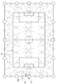
- FIG. 5 is a schematic plan view showing an example of a mode in which a plurality of physical cameras and a plurality of virtual cameras used in the image processing system according to the first and second embodiments are installed in a soccer field. It is a block diagram which shows an example of the hardware composition of the electric system of the image processing apparatus which concerns on 1st and 2nd Embodiment.
- FIG. 5 is a conceptual diagram showing an example of a plurality of captured images 46B in a time series constituting a physical camera moving image generated and output by the image processing apparatus according to the first and second embodiments. It is a block diagram which shows an example of the main part function of the image processing apparatus which concerns on 1st Embodiment. It is a conceptual diagram which shows an example of the processing content of the virtual viewpoint image generation part of the image processing apparatus which concerns on 1st Embodiment. It is a conceptual diagram which shows an example of the processing content of the output part of the image processing apparatus which concerns on 1st Embodiment.
- FIG. 14A It is a flowchart which shows an example of the flow of the output control processing which concerns on 1st Embodiment, and is the continuation of the flowchart shown in FIG. 14A. It is a conceptual diagram which shows an example of the mode of switching from the output of a reference physical camera image to the output of a virtual viewpoint image. It is a conceptual diagram which shows an example of the mode of switching from the output of a virtual viewpoint image to the output of a reference physical camera image.
- FIG. 5 is a conceptual diagram showing an example of a mode in which the output of a reference physical camera image is directly switched to the output of a virtual viewpoint image satisfying the best imaging conditions.
- FIG. 14A It is a continuation of the flowchart shown in FIG. 29A. It is a continuation of the flowchart shown in FIG. 29B.
- FIG. 29A It is a continuation of the flowchart shown in FIG. 29B.
- FIG. 29B It is a block diagram which shows an example of the mode in which the preliminary virtual viewpoint continuous shot image of a physical camera continuous shot image is stored in the storage as an image group. It is a block diagram which shows an example of a mode in which an output control program is installed in a computer of an image processing apparatus from a storage medium in which an output control program is stored.
- CPU is an abbreviation for "Central Processing Unit”.
- RAM is an abbreviation for "Random Access Memory”.
- SSD is an abbreviation for “Solid State Drive”.
- HDD is an abbreviation for “Hard Disk Drive”.
- EEPROM refers to the abbreviation of "Electrically Erasable and Programmable Read Only Memory”.
- I / F refers to the abbreviation of "Interface”.
- IC refers to the abbreviation of "Integrated Circuit”.
- ASIC refers to the abbreviation of "Application Specific Integrated Circuit”.
- PLD refers to the abbreviation of "Programmable Logic Device”.
- FPGA refers to the abbreviation of "Field-Programmable Gate Array”.
- SoC is an abbreviation for "System-on-a-chip".
- CMOS is an abbreviation for "Complementary Metal Oxide Semiconductor”.
- CCD refers to the abbreviation of "Charge Coupled Device”.
- EL refers to the abbreviation for "Electro-Luminescence”.
- GPU refers to the abbreviation of "Graphics Processing Unit”.
- WAN is an abbreviation for "Wide Area Network”.
- LAN is an abbreviation for "Local Area Network”.
- 3D refers to the abbreviation of "3 Dimensions”.
- USB is an abbreviation for "Universal Serial Bus”.
- 5G refers to the abbreviation for “5th Generation”.
- LTE is an abbreviation for “Long Term Evolution”.
- WiFi is an abbreviation for "Wireless Fidelity”.
- RTC is an abbreviation for "Real Time Clock”.
- SNMP is an abbreviation for "Simple Network Time Protocol”.
- NTP is an abbreviation for "Network Time Protocol”.
- GPS is an abbreviation for "Global Positioning System”. Exif is an abbreviation for "Exchangeable image file format for digital still cameras”.
- fps is an abbreviation for "frame per second”.
- GNSS is an abbreviation for "Global Navigation Satellite System”.
- a CPU is illustrated as an example of the “processor” according to the technology of the present disclosure, but the “processor” according to the technology of the present disclosure includes a plurality of processing devices such as a CPU and a GPU. It may be a combination of.
- the GPU operates under the control of the CPU and is responsible for executing image processing.
- match means, in addition to perfect match, an error generally allowed in the technical field to which the technology of the present disclosure belongs (to the extent that it does not contradict the purpose of the technology of the present disclosure). It refers to a match in terms of (meaning including error).
- the "same imaging time” has a meaning including an error generally allowed in the technical field to which the technology of the present disclosure belongs in addition to the completely same imaging time (in the present disclosure). It refers to the same imaging time (meaning including an error that does not go against the purpose of the technology).
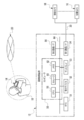
- the image processing system 10 includes an image processing device 12, a user device 14, and a plurality of physical cameras 16.
- the user device 14 is used by the user 18.
- a smartphone is applied as an example of the user device 14.
- the smartphone is merely an example, and may be, for example, a personal computer, a tablet terminal, or a portable multifunctional terminal such as a head-mounted display.
- a server is applied as an example of the image processing device 12.
- the number of servers may be one or a plurality.
- the server is merely an example, and may be, for example, at least one personal computer, or may be a combination of at least one server and at least one personal computer.
- the image processing device 12 may be at least one device capable of executing image processing.
- the network 20 is configured to include, for example, a WAN and / or a LAN.
- the network 20 includes, for example, a base station.
- the number of base stations is not limited to one, and there may be a plurality of base stations.
- the communication standards used in the base station include wireless communication standards such as 5G standard, LTE standard, WiFi (802.11) standard, and Bluetooth® standard.
- the network 20 establishes communication between the image processing device 12 and the user device 14, and transmits and receives various information between the image processing device 12 and the user device 14.
- the image processing device 12 receives a request from the user device 14 via the network 20, and provides a service according to the request to the requesting user device 14 via the network 20.
- the wireless communication method is applied as an example of the communication method between the user device 14 and the network 20 and the communication method between the image processing device 12 and the network 20.
- This is just an example, and a wired communication method may be used.
- the physical camera 16 actually exists as an object and is a visually recognizable imaging device.
- the physical camera 16 is an imaging device having a CMOS image sensor, and is equipped with an optical zoom function and / or a digital zoom function.
- CMOS image sensor instead of the CMOS image sensor, another type of image sensor such as a CCD image sensor may be applied.
- the zoom function is mounted on the plurality of physical cameras 16, but this is merely an example, and the zoom function may be mounted on a part of the plurality of physical cameras 16. However, the zoom function may not be mounted on the plurality of physical cameras 16.
- a plurality of physical cameras 16 are installed in the soccer field 22.
- the plurality of physical cameras 16 have different imaging positions (hereinafter, also simply referred to as “positions”), and the imaging direction (hereinafter, simply referred to as “direction”) of each physical camera 16 can be changed.
- positions also simply referred to as “positions”
- direction the imaging direction of each physical camera 16 can be changed.
- each of the plurality of physical cameras 16 is arranged so as to surround the soccer field 24, and an area including the soccer field 24 is imaged as an imaging area.
- the imaging by the physical camera 16 refers to, for example, imaging at an angle of view including an imaging region.
- imaging area includes the concept of an area showing a part of the soccer field 22 in addition to the concept of the area showing the whole in the soccer field 22.
- the imaging region is changed according to the imaging position, the imaging direction, and the angle of view.
- each of the plurality of physical cameras 16 is arranged so as to surround the soccer field 24
- the technique of the present disclosure is not limited to this, and for example, in the soccer field 24.
- a plurality of physical cameras 16 may be arranged so as to surround a specific part. The positions and / or orientations of the plurality of physical cameras 16 can be changed, and it is determined to be generated according to the virtual viewpoint image requested by the user 18 or the like.
- At least one physical camera 16 is installed in an unmanned aerial vehicle (for example, a multi-rotorcraft unmanned aerial vehicle), and a bird's-eye view of the area including the soccer field 24 as an imaging area from the sky. You may make an image with.
- an unmanned aerial vehicle for example, a multi-rotorcraft unmanned aerial vehicle
- a bird's-eye view of the area including the soccer field 24 as an imaging area from the sky You may make an image with.
- the image processing device 12 is installed in the control room 32.
- the plurality of physical cameras 16 and the image processing device 12 are connected via a LAN cable 30, and the image processing device 12 controls the plurality of physical cameras 16 and is imaged by each of the plurality of physical cameras 16. The image obtained by this is acquired.
- the connection using the wired communication method by the LAN cable 30 is illustrated here, the connection is not limited to this, and the connection using the wireless communication method may be used.
- the soccer stadium 22 is provided with spectator seats 26 so as to surround the soccer field 24, and the user 18 is seated in the spectator seats 26.
- the user 18 possesses the user device 14, which is used by the user 18. It should be noted that here, the example in which the user 18 exists in the soccer stadium 22 is described, but the technique of the present disclosure is not limited to this, and the user 18 is outside the soccer stadium 22. It may exist.
- the image processing device 12 acquires an image captured image 46B showing an image pickup region when observed from each position of the plurality of physical cameras 16 from each of the plurality of physical cameras 16.
- the captured image 46B is a frame image showing an imaging region when observed from the position of the physical camera 16. That is, the captured image 46B is obtained by capturing the imaging region by each of the plurality of physical cameras 16.
- the physical camera identification information that identifies the physical camera 16 used for imaging and the time when the image was taken by the physical camera 16 (hereinafter, also referred to as “physical camera imaging time”) are set for each frame. Has been granted.
- the captured image 46B is also provided with physical camera installation position information capable of specifying the installation position (imaging position) of the physical camera 16 used for imaging for each frame.
- the image processing device 12 generates an image using 3D polygons by synthesizing a plurality of captured images 46B obtained by capturing an imaging region by a plurality of physical cameras 16. Then, the image processing device 12 generates a virtual viewpoint image 46C indicating the imaging region when the imaging region is observed from an arbitrary position and an arbitrary direction, frame by frame, based on the image using the generated 3D polygon.
- the captured image 46B is an image obtained by being captured by the physical camera 16
- the virtual viewpoint image 46C is a virtual imaging device, that is, a virtual image from an arbitrary position and an arbitrary direction. It can be considered that the image is obtained by being imaged by the camera 42.
- the virtual camera 42 is a virtual camera that does not actually exist as an object and is not visually recognized.
- virtual cameras are installed at a plurality of locations in the soccer field 22 (see FIG. 3). All virtual cameras 42 are installed at different positions from each other. Further, all the virtual cameras 42 are installed at different positions from all the physical cameras 16. That is, all the physical cameras 16 and all the virtual cameras 42 are installed at different positions from each other.
- the virtual camera identification information that identifies the virtual camera 42 used for imaging and the time when the image is captured by the virtual camera 42 (hereinafter, also referred to as “virtual camera imaging time”) are set for each frame. Is given to. Further, the virtual viewpoint image 46C is provided with virtual camera installation position information capable of specifying the installation position (imaging position) of the virtual camera 42 used for imaging.
- camera installation position information when it is not necessary to distinguish between the physical camera installation position information and the virtual camera installation position information, it is referred to as "camera installation position information".
- the camera specific information, the imaging time, and the camera installation position information are added to each camera image by, for example, the Exif method.
- the image processing device 12 holds, for example, camera images for a predetermined time (for example, several hours to several tens of hours). Therefore, for example, the image processing device 12 acquires a camera image at a designated imaging time from a group of camera images for a predetermined time, and processes the acquired camera image.
- the position (hereinafter, also referred to as “virtual camera position”) 42A and the orientation (hereinafter, also referred to as “virtual camera orientation”) 42B of the virtual camera 42 can be changed.
- the angle of view of the virtual camera 42 can also be changed.
- the virtual camera position 42A is referred to in the first embodiment, the virtual camera position 42A is also generally referred to as a viewpoint position. Further, in the first embodiment, it is referred to as a virtual camera orientation 42B, but in general, the virtual camera orientation 42B is also referred to as a line-of-sight direction.
- the viewpoint position means, for example, the position of the viewpoint of a virtual person
- the line-of-sight direction means, for example, the direction of the line of sight of a virtual person.
- the virtual camera position 42A is used for convenience of explanation, but it is not essential to use the virtual camera position 42A.
- “Installing a virtual camera” means determining the viewpoint position, line-of-sight direction, and / or angle of view for generating the virtual viewpoint image 46C. Therefore, for example, the present invention is not limited to the mode in which an object such as a virtual camera is installed in the imaging region on a computer, and another method such as numerically specifying the coordinates and / or direction of the viewpoint position may be used.
- "capturing with a virtual camera” means generating a virtual viewpoint image 46C corresponding to the case where the imaging region is viewed from the position and direction in which the "virtual camera is installed".
- the virtual viewpoint image 46C a virtual viewpoint image showing an imaging area when the imaging area is observed from the virtual camera position 42A in the spectator seat 26 and the virtual camera orientation 42B is shown.
- the virtual camera position and virtual camera orientation are not fixed. That is, the virtual camera position and the virtual camera orientation can be changed according to an instruction from the user 18 or the like.
- the image processing device 12 sets the position of a person designated as a target subject (hereinafter, also referred to as “target person”) among soccer players and referees in the soccer field 24 as a virtual camera position, and sets the target person. It is also possible to set the line-of-sight direction as the direction of the virtual camera.
- virtual cameras 42 are installed at a plurality of locations in the soccer field 24 and at a plurality of locations around the soccer field 24.
- the installation mode of the virtual camera 42 shown in FIG. 3 is merely an example.
- the virtual camera 42 may not be installed in the soccer field 24 and the virtual camera 42 may be installed only around the soccer field 24, or the virtual camera 42 may not be installed around the soccer field 24 and the soccer may be installed.
- the virtual camera 42 may be installed only in the field 24.
- the number of virtual cameras 42 installed may be larger or smaller than the example shown in FIG.
- the virtual camera position 42A and the virtual camera orientation 42B of each of the virtual cameras 42 can also be changed.
- the image processing device 12 includes a computer 50, an RTC 51, a reception device 52, a display 53, a first communication I / F 54, and a second communication I / F 56.
- the computer 50 includes a CPU 58, a storage 60, and a memory 62.
- the CPU 58 is an example of a "processor” according to the technique of the present disclosure.
- the memory 62 is an example of a “memory” according to the technique of the present disclosure.
- the computer 50 is an example of a "computer” according to the technique of the present disclosure.
- the CPU 58, the storage 60, and the memory 62 are connected via the bus 64.
- the bus 64 In the example shown in FIG. 4, one bus is shown as the bus 64 for convenience of illustration, but a plurality of buses may be used. Further, the bus 64 may include a serial bus or a parallel bus composed of a data bus, an address bus, a control bus, and the like.
- the CPU 58 controls the entire image processing device 12.
- the storage 60 stores various parameters and various programs.
- the storage 60 is a non-volatile storage device.
- EEPROM is applied as an example of the storage 60.
- the memory 62 is a storage device. Various information is temporarily stored in the memory 62.
- the memory 62 is used as a work memory by the CPU 58.
- RAM is applied as an example of the memory 62.
- the RTC 51 receives drive power from a power supply system disconnected from the power supply system for the computer 50, and continues to tick the current time (for example, year, month, day, hour, minute, second) even when the computer 50 is shut down.
- the RTC 51 outputs the current time to the CPU 58 each time the current time is updated.
- the CPU 58 uses the current time input from the RTC 51 as the imaging time.
- an example in which the CPU 58 acquires the current time from the RTC 51 is given, but the technique of the present disclosure is not limited to this.
- the CPU 58 is provided from an external device (not shown) via the network 20.
- the current time may be acquired (for example, by using SNMP and / or NTP), or the current time may be acquired from a built-in or connected GNSS device (for example, GPS device). You may.
- the reception device 52 receives instructions from the user of the image processing device 12 and the like. Examples of the reception device 52 include a touch panel, hard keys, a mouse, and the like.
- the reception device 52 is connected to a bus 64 or the like, and the instruction received by the reception device 52 is acquired by the CPU 58.
- the display 53 is connected to the bus 64 and displays various information under the control of the CPU 58.
- An example of the display 53 is a liquid crystal display.
- another type of display such as an EL display (for example, an organic EL display or an inorganic EL display) may be adopted as the display 53.
- the first communication I / F 54 is connected to the LAN cable 30.
- the first communication I / F 54 is realized, for example, by a device having an FPGA.
- the first communication I / F 54 is connected to the bus 64 and controls the exchange of various information between the CPU 58 and the plurality of physical cameras 16.
- the first communication I / F 54 controls a plurality of physical cameras 16 according to the request of the CPU 58.
- the first communication I / F 54 acquires the captured image 46B (see FIG. 2) obtained by being imaged by each of the plurality of physical cameras 16, and outputs the acquired captured image 46B to the CPU 58.
- the first communication I / F 54 is exemplified as a wired communication I / F here, it may be a wireless communication I / F such as a high-speed wireless LAN.
- the second communication I / F 56 is connected to the network 20 so as to be capable of wireless communication.
- the second communication I / F56 is realized, for example, by a device having an FPGA.
- the second communication I / F 56 is connected to the bus 64.
- the second communication I / F 56 manages the exchange of various information between the CPU 58 and the user device 14 in a wireless communication system via the network 20.
- At least one of the first communication I / F54 and the second communication I / F56 can be configured by a fixed circuit instead of the FPGA. Further, at least one of the first communication I / F54 and the second communication I / F56 may be a circuit composed of an ASIC, an FPGA, and / or a PLD or the like.
- the user device 14 includes a computer 70, a gyro sensor 74, a reception device 76, a display 78, a microphone 80, a speaker 82, a physical camera 84, and a communication I / F 86.
- the computer 70 includes a CPU 88, a storage 90, and a memory 92, and the CPU 88, the storage 90, and the memory 92 are connected via a bus 94.
- one bus is shown as the bus 94 for convenience of illustration, but the bus 94 may be composed of a serial bus, or may be a data bus, an address bus, a control bus, or the like. Is configured to include.
- the CPU 88 controls the entire user device 14.
- the storage 90 stores various parameters and various programs.
- the storage 90 is a non-volatile storage device.
- EEPROM is applied as an example of the storage 90.
- this is just an example, and may be SSD, HDD, or the like.
- Various information is temporarily stored in the memory 92, and the memory 92 is used as a work memory by the CPU 88.
- RAM is applied as an example of the memory 92.
- the gyro sensor 74 includes an angle around the yaw axis of the user device 14 (hereinafter, also referred to as “yaw angle”), an angle around the roll axis of the user device 14 (hereinafter, also referred to as “roll angle”), and the user device 14.
- the angle around the pitch axis (hereinafter, also referred to as “pitch angle”) is measured.
- the gyro sensor 74 is connected to the bus 94, and the angle information indicating the yaw angle, the roll angle, and the pitch angle measured by the gyro sensor 74 is acquired by the CPU 88 via the bus 94 or the like.
- the reception device 76 receives an instruction from the user 18 (see FIGS. 1 and 2). Examples of the reception device 76 include a touch panel 76A, a hard key, and the like. The reception device 76 is connected to the bus 94, and the instruction received by the reception device 76 is acquired by the CPU 88.
- the display 78 is connected to the bus 94 and displays various information under the control of the CPU 88.
- An example of the display 78 is a liquid crystal display.
- another type of display such as an EL display (for example, an organic EL display or an inorganic EL display) may be adopted as the display 78.
- the user device 14 includes a touch panel display, and the touch panel display is realized by the touch panel 76A and the display 78. That is, the touch panel display is formed by superimposing the touch panel 76A on the display area of the display 78, or by incorporating a touch panel function (“in-cell” type) inside the display 78.
- the "in-cell” type touch panel display is merely an example, and may be an "out-sel” type or "on-cell” type touch panel display.
- the microphone 80 converts the collected sound into an electric signal.
- the microphone 80 is connected to the bus 94.
- the electric signal obtained by converting the sound collected by the microphone 80 is acquired by the CPU 88 via the bus 94.
- the speaker 82 converts an electric signal into sound.
- the speaker 82 is connected to the bus 94.
- the speaker 82 receives the electric signal output from the CPU 88 via the bus 94, converts the received electric signal into sound, and outputs the sound obtained by converting the electric signal to the outside of the user device 14.
- the physical camera 84 acquires an image showing the subject by taking an image of the subject.
- the physical camera 84 is connected to the bus 94.
- the image obtained by capturing the subject by the physical camera 84 is acquired by the CPU 88 via the bus 94.
- the image obtained by being captured by the physical camera 84 may also be used together with the captured image 46B to generate the virtual viewpoint image 46C.
- the communication I / F86 is connected to the network 20 so as to be capable of wireless communication.
- Communication I / F86 is realized, for example, by a device composed of circuits (eg, ASIC, FPGA, and / or PLD, etc.).
- the communication I / F86 is connected to the bus 94.
- the communication I / F86 controls the exchange of various information between the CPU 88 and the external device by a wireless communication method via the network 20.
- Examples of the "external device" include an image processing device 12.
- Each of the plurality of physical cameras 16 (see FIGS. 1 to 4) generates a moving image (hereinafter, also referred to as “physical camera moving image”) indicating the imaging region by imaging the imaging region.
- a moving image hereinafter, also referred to as “physical camera moving image”
- any one of the plurality of physical cameras 16 is used as the reference physical camera.
- the physical camera moving image obtained by being captured by the reference physical camera (hereinafter, also referred to as “reference physical camera moving image”) is delivered to the user device 14, and is displayed on the display 78 of the user device 14, for example. NS. Then, the user 18 appreciates the reference physical camera moving image displayed on the display 78.
- the physical camera moving image is obtained by being captured by the physical camera 16 at a specific frame rate (for example, 60 fps).
- a specific frame rate for example, 60 fps.
- the physical camera moving image is a multi-frame image composed of a plurality of frames obtained according to a specific frame rate. That is, the physical camera moving image is configured by arranging a plurality of captured images 46B obtained at each timing defined at a specific frame rate in chronological order.
- the target person is an example of the "object” according to the technique of the present disclosure
- the target person image 96 is an example of the "object image” according to the technique of the present disclosure.
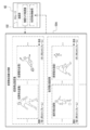
- the captured images 46B1 to 46B3 for three frames are roughly classified into the captured image 46B1 of the first frame, the captured image 46B2 of the second frame, and the captured image 46B3 of the third frame from the oldest frame to the latest frame. ..
- the entire target person image 96 appears at a position that can be visually recognized including the facial expression of the target person.
- the captured image 46B2 of the second frame and the captured image 46B3 of the third frame most of the area including the face of the target person in the target person image 96 cannot be visually recognized by the person image showing the person other than the target person. It has been blocked by the level.
- the physical camera moving image shown in FIG. 6 is displayed on the display 78 of the user device 14 as the reference physical camera moving image
- the user 18 has the target person image 96 from the captured images 46B2 and 46B3 of at least the second and third frames. It becomes difficult to grasp the whole aspect of.
- the facial expression of the target person cannot be observed from at least the captured images 46B2 and 46B3 of the second and third frames. ..
- the output control program 100 is stored in the storage 60. Then, the CPU 58 executes the output control process (FIGS. 14A and 14B) described later according to the output control program 100.
- the CPU 58 reads the output control program 100 from the storage 60 and executes the output control program 100 on the memory 62 to perform the virtual viewpoint image generation unit 58A, the image acquisition unit 58B, the detection unit 58C, the output unit 58D, and the image selection. Operates as part 58E.
- the image group 102 is stored in the storage 60.
- the image group 102 includes a physical camera moving image and a virtual viewpoint moving image.
- the physical camera moving image is roughly divided into a reference physical camera moving image and another physical camera moving image obtained by being captured by a physical camera 16 (hereinafter, also referred to as “other physical camera”) other than the reference physical camera. Will be done.
- the reference physical camera moving image includes a plurality of captured images 46B obtained by being captured by the reference physical camera as reference physical camera images in chronological order.
- the moving image of the other physical camera includes a plurality of captured images 46B obtained by being captured by the other physical camera in chronological order as images of the other physical camera.
- the virtual viewpoint moving image is obtained by being captured by the virtual camera 42 (see FIGS. 2 and 3) at a specific frame rate.
- the virtual viewpoint moving image is a multi-frame image composed of a plurality of frames obtained according to a specific frame rate. That is, the virtual viewpoint moving image is configured by arranging a plurality of virtual viewpoint images 46C obtained at each timing defined at a specific frame rate in chronological order.
- a plurality of virtual cameras 42 exist, and each virtual camera 42 obtains a virtual viewpoint moving image and stores it in the storage 60.
- a camera image obtained by taking an image with a camera other than the reference physical camera will be referred to as an "other camera image”. That is, the other camera image is a general term for the other physical camera image and the virtual viewpoint image.
- the detection unit 58C performs the detection process.
- the detection process is a process of detecting a target person image 96 from each of a plurality of camera images obtained by being imaged by a plurality of cameras having different positions.
- the target person image 96 is detected by detecting the face image showing the face of the target person. Examples of the detection process include a first detection process (see FIG. 11) described later and a second detection process (see FIG. 12) described later.
- the output unit 58D outputs a reference physical camera image among a plurality of camera images. Further, when the output unit 58D transitions from the detection state in which the target person image 96 is detected from the reference physical camera image by the detection process to the non-detection state in which the target person image 96 is not detected from the reference physical camera image by the detection process. , Of the plurality of camera images, the other camera image in which the target person image 96 is detected by the detection process is output. For example, the output unit 58D switches from the output of the reference physical camera image to the output of another camera image when the state transitions from the detection state to the non-detection state while the reference physical camera image is being output.
- the transition from the detection state to the non-detection state means that the reference physical camera image to be output by the output unit 58D does not include the target person from the reference physical camera image in which the target person is captured. It means to switch to the reference physical camera image.
- the transition from the detected state to the non-detected state means that the target person is captured between frames that are temporally adjacent to each other among a plurality of reference physical camera images included in the reference physical camera moving image. This means that the output target by the output unit 58D is switched from the existing frame to the frame in which the target person is not reflected.
- an object in the imaging region (for example, a target person or an object around the target person, etc.) as shown in the captured images 46B1 to 46B2 shown in FIG. ) Moves from a state in which the target person image 96 can be detected to a state in which it is hidden by another person or the like and cannot be detected.
- the camera image is an example of the "image” according to the technique in the present disclosure.
- the reference physical camera image is an example of the "first image” according to the technique of the present disclosure.
- the other camera image is an example of the "second image” according to the technique of the present disclosure.
- the virtual viewpoint image generation unit 58A generates a plurality of virtual viewpoint moving images by causing each of all the virtual cameras 42 to take an image.
- the virtual viewpoint image generation unit 58A acquires a physical camera moving image from the storage 60.
- the virtual viewpoint image generation unit 58A is based on the physical camera moving image acquired from the storage 60, and the virtual viewpoint moving image according to the virtual camera position, the virtual camera orientation, and the angle of view currently set for each virtual camera 42. Generate an image.
- the virtual viewpoint image generation unit 58A stores the generated virtual viewpoint moving image in the storage 60 in units of the virtual cameras 42.
- the virtual camera position, the virtual camera orientation, and the virtual viewpoint moving image according to the angle of view that are set at the present time are, for example, from the virtual camera position and the virtual camera orientation that are set at the present time. It means a moving image showing the observed area at the angle of view set in.
- the virtual viewpoint image generation unit 58A generates a plurality of virtual viewpoint moving images by causing each of all the virtual cameras 42 to take an image is given, but not all virtual viewpoint images are necessarily generated. It is not necessary to have each of the cameras 42 perform imaging, and for example, depending on the performance of a computer or the like, it may be possible that some virtual cameras 42 do not generate a virtual viewpoint moving image.
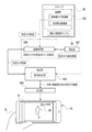
- the output unit 58D acquires the reference physical camera moving image from the storage 60 and outputs the acquired reference physical camera moving image to the user device 14. As a result, the reference physical camera moving image is displayed on the display 78 of the user device 14.
- the user 18 sets the area of interest (hereinafter, also referred to as “attention area”) on the touch panel 76A. Specify with your finger via.
- the region of interest is the region including the target person image 96 in the reference physical camera moving image displayed on the display 78.
- the user device 14 transmits the attention area information indicating the attention area in the reference physical camera moving image to the image acquisition unit 58B.
- the image acquisition unit 58B receives the attention area information transmitted from the user device 14.
- the image acquisition unit 58B performs image analysis (for example, image analysis by a cascade classifier and / or pattern matching, etc.) on the received attention area information, and from the attention area indicated by the attention area information, the target person image. 96 is extracted.
- the image acquisition unit 58B stores the target person image 96 extracted from the region of interest as the target person image sample 98 in the storage 60.
- the image acquisition unit 58B acquires the reference physical camera image in units of one frame from the reference physical camera moving image in the storage 60.
- the detection unit 58C executes the first detection process.
- the reference physical camera image acquired by the image acquisition unit 58B is subjected to image analysis using the target person image sample 98 in the storage 60, so that the target person image 96 is obtained from the reference physical camera image.
- Examples of the image analysis include image analysis by a cascade classifier and / or pattern matching and the like.
- the target person image 96 detected by the first detection process also includes an image showing a target person having a mode different from that of the target person shown by the target person image 96 shown in FIG. That is, the detection unit 58C determines whether or not the target person indicated by the target person image sample 98 is reflected in the reference physical camera image by executing the first detection process.
- the output unit 58D uses the reference physical camera image processed by the first detection process, that is, the reference physical camera image including the target person image 96 as a user device. Output to 14. As a result, the reference physical camera image including the target person image 96 is displayed on the display 78 of the user device 14.
- the image acquisition unit 58B has the same imaging time as the reference physical camera image processed by the first detection process. Acquire a plurality of other camera images from the storage 60. In the following, for convenience of explanation, a plurality of other camera images will also be referred to as "other camera image group".
- the detection unit 58C executes the second detection process for each of the other camera images included in the other camera image group acquired by the image acquisition unit 58B.
- the second detection process differs from the first detection process in that another camera image is used as a processing target instead of the reference physical camera image.
- the image selection unit 58E selects the image selection unit 58E from the other camera image group including the target person image 96 detected by the second detection process. Select another camera image that meets the best imaging conditions.
- the best imaging condition is, for example, that the position of the target person image 96 in the other camera image is within the predetermined range and the size of the target person image 96 in the other camera image is within the predetermined range. Refers to the condition that the size is larger than the default size.
- the best imaging condition the condition that the entire target person shown by the target person image 96 is most reflected in the predetermined central frame in the central portion of the frame is used. ing.
- the shape and / or size of the central frame may be fixed or may be changed according to given instructions and / or conditions.
- the frame is not limited to the central frame, and a frame may be provided at another position.
- condition that the entire target person is reflected in the central frame is illustrated, but this is just an example, and the face of the target person is included in the central frame. It may be a condition that an area of a predetermined ratio (for example, 80%) or more is reflected.
- the default ratio may be a fixed value or a variable value that is changed according to a given instruction and / or condition.
- the image selection unit 58E selects and selects other camera images that satisfy the best imaging conditions from the other camera image group including the target person image 96 detected by the second detection process.
- the camera image is output to the output unit 58D.
- the detection unit 58C outputs the other camera image in which the target person image 96 is detected to the output unit 58D. ..
- the output unit 58D outputs another camera image input from the detection unit 58C or the image selection unit 58E to the user device 14. As a result, another camera image including the target person image 96 is displayed on the display 78 of the user device 14.
- the output unit 58D uses the user device 14 as a reference physical camera image to be processed by the first detection process. Output to. In this case, the reference physical camera image in which the target person image 96 is not detected by the first detection process is output to the user device 14. As a result, the display 78 of the user device 14 displays the reference physical camera image in which the target person image 96 was not detected by the first detection process.
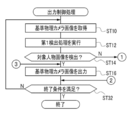
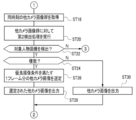
- FIGS. 14A and 14B show an example of the flow of output control processing executed by the CPU 58.
- the flow of the output control process shown in FIGS. 14A and 14B is an example of the "image processing method" according to the technique of the present disclosure.
- the description of the output control process shown below is based on the premise that the image group 102 is already stored in the storage 60 for convenience of explanation. Further, the description of the output control process shown below is based on the premise that the target person image sample 98 is already stored in the storage 60 for convenience of explanation.
- step ST10 the image acquisition unit 58B acquires an unprocessed reference physical camera image for one frame from the reference physical camera moving image in the storage 60, and then outputs the image.
- the control process proceeds to step ST12.
- the unprocessed reference physical camera image refers to a reference physical camera image that has not yet been processed in step ST12.
- step ST12 the detection unit 58C executes the first detection process on the reference physical camera image acquired in step ST10, and then the output control process shifts to step ST14.
- step ST14 the detection unit 58C determines whether or not the target person image 96 is detected from the reference physical camera image by the first detection process. In step ST14, if the target person image 96 is not detected from the reference physical camera image by the first detection process, the determination is denied and the output control process shifts to step ST18 shown in FIG. 14B. When the target person image 96 is detected from the reference physical camera image by the first detection process in step ST14, the determination is affirmed and the output control process shifts to step ST16.
- step ST16 the output unit 58D outputs the reference physical camera image processed by the first detection process of step ST14 to the user device 14, and then the output control process shifts to step ST32.
- the reference physical camera image is output to the user device 14 by executing the process of step ST16, the reference physical camera image is displayed on the display 78 of the user device 14 (see FIG. 11).
- step ST18 shown in FIG. 14B the image acquisition unit 58B acquires another camera image group having the same imaging time as the reference physical camera image processed by the first detection process from the storage 60, and then outputs control process. Moves to step ST20.
- step ST20 the detection unit 58C executes the second detection process on the other camera image group acquired in step ST18, and then the output control process shifts to step ST22.
- step ST22 the detection unit 58C determines whether or not the target person image 96 is detected from the other camera image group acquired in step ST18. If the target person image 96 is not detected from the other camera image group acquired in step ST22 in step ST22, the determination is denied and the output control process shifts to step ST16 shown in FIG. 14A. In step ST22, when the target person image 96 is detected from the other camera image group acquired in step ST18, the determination is affirmed, and the output control process shifts to step ST24.
- step ST24 the detection unit 58C determines whether or not there are a plurality of other camera images in which the target person image 96 is detected by the second detection process. In step ST24, when there are a plurality of other camera images in which the target person image 96 is detected by the second detection process, the determination is affirmed and the output control process shifts to step ST26. In step ST24, if the other camera image in which the target person image 96 is detected by the second detection process is one frame, the determination is denied and the output control process shifts to step ST30.
- step ST26 the image selection unit 58E selects another camera image satisfying the best imaging conditions (see FIG. 12) from the other camera image group in which the target person image 96 is detected by the second detection process, and then outputs control. The process proceeds to step ST28.
- step ST28 the output unit 58D outputs the other camera image selected in step ST26 to the user device 14, and then the output control process shifts to step ST32 shown in FIG. 14A.
- the other camera image is output to the user device 14 by executing the process of step ST28, the other camera image is displayed on the display 78 of the user device 14 (see FIG. 13).
- step ST30 the output unit 58D outputs another camera image in which the target person image 96 is detected by the second detection process to the user device 14, and then the output control process shifts to step ST32 shown in FIG. 14A.
- the other camera image is output to the user device 14 by executing the process of step ST30, the other camera image is displayed on the display 78 of the user device 14 (see FIG. 13).
- step ST32 shown in FIG. 14A the output unit 58D determines whether or not the condition for terminating the output control process (hereinafter, also referred to as “output control process end condition”) is satisfied.
- the output control processing end condition there is a condition that the image processing apparatus 12 is instructed to end the output control process.
- the instruction to end the output control process is received by, for example, the receiving device 52 or 76. If the output control process end condition is not satisfied in step ST32, the determination is denied and the output control process shifts to step ST10. If the output control process end condition is satisfied in step ST32, the determination is affirmed and the output control process ends.
- the reference physical camera image in which the target person image 96 is not obstructed by obstacles is output to the user device 14 by the output unit 58D.
- the entire target person image 96 is visually recognized instead of the reference physical camera image in which the target person image 96 is obstructed by the obstacle.
- a possible virtual viewpoint image 46C is output to the user device 14 by the output unit 58D. As a result, it is possible to continuously provide the user 18 with a camera image capable of observing the target person.
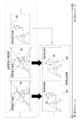
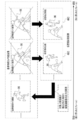
- the target person image 96 is blocked by an obstacle in the reference physical camera image under the condition that the reference physical camera moving image is output.
- the output of the reference physical camera moving image is switched to the output of the virtual viewpoint moving image.
- the output unit 58D reaches a state in which the target person image 96 is blocked by an obstacle in the reference physical camera image. Switch from the output of the reference physical camera moving image to the output of the virtual viewpoint moving image. Then, the output unit 58D ends the output of the virtual viewpoint moving image at a timing after the timing when the target person image 96 reaches the state of being blocked by the obstacle in the reference physical camera image. That is, the output of the virtual viewpoint moving image ends at a timing after the timing at which the target person image 96 is not detected by the first detection process. As a result, it is possible to provide the user 18 with a virtual viewpoint moving image capable of observing the target person after the target person image 96 is not detected by the first detection process.
- the target person image 96 is blocked by an obstacle in the reference physical camera image, and then the target person image 96 is included in the reference physical camera image.
- the output unit 58D restarts the output of the reference physical camera moving image on condition that the camera returns to a state where it is not blocked by an obstacle. That is, the virtual viewpoint is provided on the condition that the target person image 96 is not detected from the reference physical camera image by the first detection process and the target person image 96 is detected from the reference physical camera image by the first detection process.
- the output of the moving image can be switched to the output of the moving image of the reference physical camera.
- the target person image 96 is not blocked by the obstacle in the reference physical camera image, the target person image 96 is not blocked by the obstacle in the reference physical camera image. Compared with the case where the output of the virtual viewpoint moving image is continued, it is possible to reduce the trouble of switching from the output of the virtual viewpoint moving image to the output of the reference physical camera moving image.
- the target person image 96 is detected by detecting the face image showing the face of the target person by the first detection process and the second detection process. Therefore, the target person image 96 can be detected with higher accuracy than the case where the face image is not detected.
- a plurality of frame images composed of a plurality of frames are output to the user device 14 by the output unit 58D.
- Examples of the multi-frame image include a reference physical camera moving image and a virtual viewpoint moving image as shown in FIGS. 15 and 16. Therefore, according to this configuration, the user 18 who is viewing the reference physical camera moving image and the virtual viewpoint moving image can continuously observe the target person.
- the imaging area is imaged by the plurality of physical cameras 16, and the imaging area is also imaged by the plurality of virtual cameras 42. Therefore, as compared with the case where the imaging region is imaged only by the physical camera 16 without using the virtual camera 42, the user 18 can observe the target person from various positions and directions.
- a plurality of physical cameras 16 and a plurality of virtual cameras 42 are illustrated, but the technique of the present disclosure is not limited to this, and the number of physical cameras 16 may be one, or the virtual cameras 42. The number of units may be one.
- the output of the virtual viewpoint moving image has been described with reference to a form example in which the output of the virtual viewpoint moving image is terminated at a timing after the timing at which the target person image 96 is not detected by the first detection process.
- the technology of the present disclosure is not limited to this.
- the output unit 58D outputs the virtual viewpoint moving image. May be started from a timing before the timing at which the target person image 96 is not detected by the first detection process.
- the timing at which the target person image 96 is not detected in the reference physical camera moving image can be recognized, so that the target person image 96 is not detected in the reference physical camera moving image. It is possible to output a virtual viewpoint moving image before the timing. As a result, it is possible to provide the user 18 with a virtual viewpoint moving image capable of observing the target person before the target person image 96 is not detected by the first detection process.
- the first embodiment when there are a plurality of other camera images in which the target person image 96 is detected by the second detection process, another camera image satisfying the best imaging conditions is output. As mentioned above, it is not always necessary to output other camera images that satisfy the best imaging conditions. For example, if any other camera image in which the target person image 96 is detected is output, the user 18 can visually recognize the target person image 96.
- the position of the target person image 96 in the other camera image group is within the predetermined range, and the position in the other camera image is within the predetermined range.
- the best imaging condition is that the position of the target person image 96 in the other camera image is within the predetermined range in the other camera image group, or the target person image 96 in the other camera image. It may be a condition that the size is larger than the default size.
- the output of the reference physical camera image can be directly switched to the output of the virtual viewpoint image 46C that satisfies the best imaging condition.
- the techniques of the present disclosure are not limited to this. If the output of the reference physical camera image is directly switched to the output of the virtual viewpoint image 46C that satisfies the best imaging conditions, it may be difficult to grasp the position of the target person before and after the output is switched.
- the output unit 58D continuously changes the position, orientation, and angle of view during the period of switching from the output of the reference physical camera image to the output of the virtual viewpoint image 46C that satisfies the best imaging condition.
- the camera image obtained by being imaged by a plurality of connected cameras is output.
- the camera image obtained by being captured by a plurality of cameras that continuously connect the position, orientation, and angle of view is, for example, the best imaging condition from the imaging position, imaging direction, and angle of view of the reference physical camera.
- the target person image 96 when the target person image 96 is obstructed by an obstacle in the reference physical camera image, the target person image 96 is replaced with the reference physical camera image obstructed by the obstacle.
- a form example in which a virtual viewpoint image 46C or another physical camera image in which the entire target person image 96 can be visually recognized can be output to the user device 14 by the output unit 58D has been described.
- the entire target person image 96 is replaced with the reference physical camera image in which the target person image 96 is obstructed by the obstacle. Only the visible virtual viewpoint image 46C may be output.
- the user 18 can be provided with the virtual viewpoint moving image to continue observing the target person.
- the viewpoint image 46C or another physical camera image may be output.
- This particular part may be configurable according to instructions given by the user 18. For example, when the face indicated by the target person image 96 is set according to the instruction given by the user 18, the virtual viewpoint image 46C or another physical camera image in which the face of the target person can be visually recognized is output. Further, for example, the virtual viewpoint image 46C or another physical camera image in which the target person image 96 can be visually recognized may be output at a ratio larger than the ratio of the target person image 96 that can be visually recognized in the reference physical camera image.
- the image in which the target person image 96 is detected by the above detection process does not necessarily have to be output.
- the three-dimensional position of each object in the imaging region is recognized by triangulation or the like and the target person image 96 is obstructed by an obstacle in the reference physical camera image, the target person, the obstacle, and other objects.
- the virtual viewpoint image 46C showing the mode observed from the viewpoint position, direction, and angle of view estimated to be visible to the target person may be output from the positional relationship of the above.
- the detection process in the technique of the present disclosure also includes a process based on such estimation.
- a reference virtual viewpoint moving image composed of a plurality of time-series virtual viewpoint images 46C obtained by being imaged by a specific virtual camera 42 instead of the reference physical camera moving image. May be output to the user device 14 by the output unit 58D.
- the output of the reference virtual viewpoint moving image is switched to the output of another camera image (in the example shown in FIG. 19, a virtual viewpoint moving image other than the reference virtual viewpoint moving image). In this way, even when the output of the reference virtual viewpoint moving image can be switched to the output of the other camera image, the target person is continuously observed for the user 18 as in the first embodiment. Can be made to.
- the physical camera image and the virtual viewpoint image 46C have been described with reference to a form example in which the physical camera image and the virtual viewpoint image 46C are selectively output by the output unit 58D.
- the output is switched. Regardless of whether it is before or after, only the virtual viewpoint image 46C may be output by the output unit 58D. In this case as well, the user 18 can be made to continuously observe the target person as in the first embodiment.
- a bird's-eye view image including the target person image 96 may be output to the user device 14 by the output unit 58D as another camera image.
- the bird's-eye view image refers to an image showing a bird's-eye view of the imaging region (in the example shown in FIG. 20, the entire soccer field 24).
- the output unit 58D outputs a bird's-eye view image. It may be done. Therefore, according to the form example in which the bird's-eye view image is output by the output unit 58D, the target person is reflected as compared with the case where the camera image obtained by capturing only a part of the imaging region is output. It is possible to provide the user 18 with a camera image that is likely to be present.
- the reference physical camera moving image may be an image for television broadcasting.
- the image for television broadcasting include a recorded moving image or a moving image for live broadcasting.
- the image is not limited to a moving image, and may be a still image.
- the target person image 96 is blocked by an obstacle in the television broadcast image.
- a usage method is assumed in which a virtual viewpoint image 46C or another physical camera image in which the target person image 96 can be visually recognized is output to the user device 14 by using the technique described in the first embodiment. Therefore, according to the embodiment in which the image for television broadcasting is used as the reference physical camera moving image, even when the user 18 is viewing the image for television broadcasting, the target person is referred to the user 18 with respect to the user 18. It can be observed continuously.
- the installation position of the reference physical camera is not particularly determined, but the reference physical camera is an observation position for observing an imaging region (for example, a soccer field 24) among a plurality of physical cameras 16. Or, it is preferable that the physical camera 16 is installed in the vicinity of the observation position.
- the reference virtual viewpoint moving image is output by the output unit 58D instead of the reference physical camera moving image, it is installed at the observation position for observing the imaging area (for example, the soccer field 24) or near the observation position.
- the imaging region may be imaged by the virtual camera 42.
- the observation position for example, the position of the user 18 seated in the spectator seat 26 shown in FIG. 1 can be mentioned.
- the camera installed near the observation position for example, the camera installed at the position closest to the user 18 seated in the spectator seat 26 shown in FIG. 1 (for example, the physical camera 16 or the virtual camera 42). Can be mentioned.
- the user 18 views a camera image obtained by being imaged by an observation position for observing an imaging area or a camera installed in the vicinity of the observation position among a plurality of cameras. Even if there is, the user 18 can be made to continuously observe the target person.
- the reference physical camera is capturing the same region as or close to the region that the user 18 is viewing. Therefore, when the user 18 is directly looking at the imaging region (when directly observing in the real space), it can be detected from the reference physical camera moving image that the target person cannot be seen by the user 18.
- the virtual viewpoint image 46C or another physical camera image in which the target person image 96 can be visually recognized can be output to the user device 14.
- the target person when the state in which the target person image 96 is detected by the first detection process is changed to the state in which the target person image 96 is not detected, the target person is output from the output of the reference physical camera moving image.
- the technique of the present disclosure is not limited to this. For example, as shown in FIG. 21, even when the state in which the target person image 96 is detected by the first detection process is changed to the state in which the target person image 96 is not detected, the output unit 58D is still a reference physical camera.
- the output of the moving image may be continued, and the virtual viewpoint moving image capable of observing the target person image 96 may be output in parallel.
- the reference physical camera moving image and the virtual viewpoint moving image are displayed in parallel on the display 78 of the user device 14 which is the output destination of the camera image on different screens.
- the user 18 can continuously observe the target person through the reference physical camera moving image and the virtual viewpoint moving image while viewing the reference physical camera moving image.
- the reference virtual viewpoint moving image may be output to the user device 14 by the output unit 58D.
- another physical camera moving image may be output to the user device 14 by the output unit 58D.
- the reference physical camera moving image and the virtual viewpoint moving image are output to separate user devices 14 (one unit is not shown). You may do so.
- the target person image 96 is illustrated, but the technique of the present disclosure is not limited to this, and an image showing a non-person (object other than a human) may be used.
- a non-person a robot equipped with a device capable of recognizing an object (for example, a physical camera and a device including a computer connected to the physical camera) (for example, a robot that imitates a living thing such as a person, an animal, or an insect). , Animals, insects and the like.
- the other camera image including the target person image 96 is output by the output unit 58D, but the second embodiment does not include the target person image 96 depending on the conditions.
- An example of a form in which another camera image is also output by the output unit 58D will be described.
- the same components as those in the first embodiment are designated by the same reference numerals, and the description thereof will be omitted.
- the second embodiment a part different from the first embodiment will be described. Further, in the following, for convenience of explanation, when it is not necessary to distinguish between the moving image of another physical camera and the moving image of the virtual viewpoint, the moving image of another camera is referred to as a moving image of another camera.
- any one camera other than the reference physical camera among the plurality of cameras is regarded as a specific camera, and among the plurality of cameras, the reference physical camera and Cameras other than the specific camera are regarded as non-specific cameras.
- An example of the specific camera is a camera used in imaging for obtaining another camera image output by the output unit 58D by executing the process of step ST28 or step ST30 shown in FIG. 14B.
- the specific camera is an example of the "second image camera" according to the technique of the present disclosure.
- a third detection process and a fourth detection process are performed.
- the third detection process is a process of detecting the target person image 96 from the specific camera image which is another camera image obtained by being imaged by the specific camera.
- the specific camera image is an example of a "second image" according to the technique of the present disclosure.
- the target person image 96 is detected by detecting the face image showing the face of the target person.
- the other camera image that is the detection target of the face image is a specific camera image.
- the types of a plurality of frames constituting the other camera moving image obtained by being captured by the specific camera are the detection frame in which the target person image 96 is detected by the third detection process and the target person image by the third detection process. 96 is roughly classified into undetected frames that have not been detected.
- another camera moving image obtained by being captured by a specific camera is also referred to as a “specific camera moving image”.
- the fourth detection process is a process of detecting the target person image 96 from the non-specific camera image which is another camera image obtained by being imaged by the non-specific camera.
- the non-specific camera image in which the target person image 96 is detected by the fourth detection process is an example of the “third image” according to the technique of the present disclosure.
- the non-specific camera used in the imaging for obtaining the non-specific camera image in which the target person image 96 is detected by the fourth detection process is an example of the "third image camera” according to the technique of the present disclosure.
- the target person image 96 is detected by detecting the face image showing the face of the target person.
- the camera image to be detected of the face image is a non-specific camera image.
- the CPU 58 when the specific camera moving image includes a detection frame and a non-detection frame, the CPU 58 describes the distance between the position of the specific camera and the position of the non-specific camera, and the first embodiment.
- the non-detection frame and the non-specific camera image are selectively output according to the time of the non-detection state.
- the CPU 58 does not detect when the distance between the position of the specific camera and the position of the non-specific camera exceeds the threshold value and satisfies the non-detection frame output condition that the non-detection state time is less than the predetermined time.
- a frame is output, and when the non-detection frame output condition is not satisfied, a non-specific camera image is output instead of the non-detection frame.
- the CPU 58 of the image processing device 12 As shown in FIG. 23 as an example, the point that the CPU 58 of the image processing device 12 according to the second embodiment further operates as the setting unit 58F, the determination unit 58G, and the calculation unit 58H will be described in the first embodiment. It is different from the CPU 58 of the image processing device 12.
- the setting unit 58F is output by the output unit 58D.
- the camera used for imaging to obtain a camera image is set as a specific camera.
- the setting unit 58F acquires camera identification information from another camera image output by the output unit 58D. Then, the setting unit 58F holds the camera specific information acquired from the image of another camera as the specific camera identification information that can identify the specific camera.
- the image acquisition unit 58B acquires the specific camera identification information from the setting unit 58F. Then, the image acquisition unit 58B is the same as the reference physical camera image processed by the first detection process from the specific camera moving image obtained by being imaged by the specific camera specified from the specific camera identification information. Acquires a specific camera image at the imaging time.
- the detection unit 58C executes the third detection process on the specific camera image acquired by the image acquisition unit 58B using the target person image sample 98 in the same manner as the first and second detection processes.
- the output unit 58D outputs the specific camera image including the target person image 96 detected by the third detection process to the user device 14.
- the display 78 of the user device 14 displays the specific camera image including the target person image 96 detected by the third detection process.
- the determination unit 58G has a non-detection duration of less than a predetermined time (for example, 3 seconds). Judge whether or not.
- the non-detection duration refers to the time of the non-detection state, that is, the time during which the non-detection state continues.
- the default time may be a fixed time or a variable time that is modified according to given instructions and / or conditions.
- the image is displayed.
- the acquisition unit 58B acquires the specific camera identification information from the setting unit 58F.
- the image acquisition unit 58B uses the specific camera identification information from the image group 102 to obtain a specific camera image among a plurality of other camera images having the same imaging time as the reference physical camera image processed by the first detection process. All non-specific camera images other than the above (hereinafter, also referred to as "non-specific camera image group") are acquired.
- the detection unit 58C performs a fourth detection process on the non-specific camera image group acquired by the image acquisition unit 58B using the target person image sample 98 in the same manner as the first to third detection processes. Run.
- the calculation unit 58H is added to the non-specific camera image in which the target person image 96 is detected by the fourth detection process.
- the camera specific information is acquired as the non-specific camera identification information that can identify the non-specific camera used in the imaging for obtaining the non-specific camera image.
- the calculation unit 58H uses the camera installation position information regarding the specific camera specified by the specific camera identification information held by the setting unit 58F and the camera installation position information regarding the non-specific camera specified by the non-specific camera identification information. , The distance between the specific camera and the non-specific camera (hereinafter, also referred to as "camera distance") is calculated. The calculation unit 58H calculates the camera distance for each non-specific camera identification information, that is, for each non-specific camera image in which the target person image 96 is detected by the fourth detection process.
- the determination unit 58G acquires the shortest camera distance (hereinafter, also referred to as "shortest camera distance") among the camera distances calculated by the calculation unit 58H. Then, the determination unit 58G determines whether or not the shortest camera distance exceeds the threshold value.
- the threshold value may be a fixed value or a variable value that is changed according to a given instruction and / or condition.
- the output unit 58D detects the specific camera image acquired by the image acquisition unit 58B, that is, the target person image 96 by the third detection process.
- the missing specific camera image is output to the user device 14.
- the output unit 58D is the target by the specific camera image acquired by the image acquisition unit 58B, that is, the third detection process.
- the specific camera image in which the person image 96 is not detected is output to the user device 14.
- the display 78 of the user device 14 displays the specific camera image that does not include the target person image 96.
- the determination unit 58G determines that the shortest camera distance is equal to or less than the threshold value, the non-detection duration is equal to or longer than the predetermined time, and the target person image 96 is detected by the fourth detection process.
- An example of the processing content of the CPU 58 in the case is shown.
- the calculation unit 58H outputs the shortest distance non-specific camera identification information to the image acquisition unit 58B and the setting unit 58F.
- the shortest distance non-specific camera identification information refers to non-specific camera identification information that can identify the non-specific camera that is the target of calculation of the shortest camera distance calculated by the calculation unit 58H.
- the image acquisition unit 58 is a non-specific camera obtained by being captured by a non-specific camera specified by the non-specific camera identification information among the non-specific camera images in which the target person image 96 is detected by the fourth detection process. Acquires the shortest distance non-specific camera image which is an image.
- the output unit 58D outputs the shortest distance non-specific camera image acquired by the image acquisition unit 58B to the user device 14. As a result, the shortest distance non-specific camera image is displayed on the display 78 of the user device 14. Since the target person image 96 is included in the shortest distance non-specific camera image, the user 18 can observe the target person through the display 78.
- the output unit 58D When the output of the shortest distance non-specific camera image is completed, the output unit 58D outputs the output completion information to the setting unit 58F.
- the setting unit 58F is specified from the shortest distance non-specific camera identification information input from the calculation unit 58H instead of the specific camera currently set.
- a camera hereinafter, also referred to as a “shortest distance non-specific camera” is set as a specific camera.
- FIGS. 29A to 29C are different from the flowcharts shown in FIGS. 14A and 14B in that they have steps ST100 to ST138.
- steps ST100 to ST138 are different from the flowcharts shown in FIGS. 14A and 14B.
- step ST100 the detection unit 58C determines whether or not the specific camera has not been set. For example, here, the detection unit 58C determines that the specific camera has not been set when the setting unit 58F does not hold the specific camera identification information, and the setting unit 58F holds the specific camera identification information. , It is determined that the specific camera is not set (the specific camera is set).
- step ST100 If the specific camera is not set in step ST100, the determination is affirmed and the output control process shifts to step ST18. If the specific camera is not set in step ST100, the determination is denied, and the output control process shifts to step ST104 shown in FIG. 29B.
- step ST102 the setting unit 58F sets the camera used for imaging for obtaining the other camera image output in step ST28 or step ST30 to the specific camera, and then the output control process is performed in the step shown in FIG. 14A. Move to ST32.
- step ST104 shown in FIG. 29B a specific camera image having the same imaging time as the reference physical camera image processed by the first detection process is acquired from the specific camera moving image obtained by capturing the image by the specific camera. After that, the output control process proceeds to step ST106.
- step ST106 the detection unit 58C executes the third detection process using the target person image sample 98 for the specific camera image acquired in step ST104, and then the output control process shifts to step ST108.
- step ST108 the detection unit 58C determines whether or not the target person image 96 is detected from the specific camera image by the third detection process. If the target person image 96 is not detected from the specific camera image by the third detection process in step ST108, the determination is denied and the output control process shifts to step ST112. When the target person image 96 is detected from the specific camera image by the third detection process in step ST108, the determination is affirmed and the output control process shifts to step ST110.
- step ST110 the output unit 58D outputs the detection target specific camera image of the third detection process to the user device 14, and then the output control process shifts to step ST32 shown in FIG. 14A.
- step ST112 the determination unit 58G determines whether or not the non-detection duration is less than the predetermined time. In step ST112, if the non-detection duration is equal to or longer than the predetermined time, the determination is denied and the output control process shifts to step ST128 shown in FIG. 29C. If the non-detection duration is less than the predetermined time in step ST112, the determination is affirmed and the output control process shifts to step ST114.
- step ST114 the detection unit 58C executes the fourth detection process on the non-specific camera image group using the target person image sample 98, and then the output control process shifts to step ST116.
- step ST116 the detection unit 58C determines whether or not the target person image 96 is detected from the non-specific camera image group by the fourth detection process. If the target person image 96 is not detected from the non-specific camera image group by the fourth detection process in step ST116, the determination is denied and the output control process shifts to step ST110. When the target person image 96 is detected from the non-specific camera image group by the fourth detection process in step ST116, the determination is affirmed and the output control process shifts to step ST118.
- step ST118 first, the calculation unit 58H captures the camera specific information given to the non-specific camera image in which the target person image 96 is detected by the fourth detection process of step ST114 to obtain the non-specific camera image.
- the non-specific camera used in is acquired as identifiable non-specific camera identification information.
- the calculation unit 58H determines the camera installation position information regarding the specific camera specified by the specific camera identification information held by the setting unit 58F, and the camera installation position information regarding the non-specific camera specified by the non-specific camera identification information. Is used to calculate the camera distance.
- the camera distance is calculated for each non-specific camera image in which the target person image 96 is detected by the fourth detection process in step ST114.
- the output control process shifts to step ST120.
- step ST120 the determination unit 58G determines whether or not the shortest camera distance among the camera distances calculated in step ST118 exceeds the threshold value. If the shortest camera distance is equal to or less than the threshold value in step ST120, the determination is denied and the output control process shifts to step ST122. If the shortest camera distance exceeds the threshold value in step ST120, the determination is affirmed, and the output control process shifts to step ST110.
- step ST122 first, the image acquisition unit 58B acquires the shortest distance non-specific camera identification information from the calculation unit 58H. Then, the image acquisition unit 58B obtains the shortest distance non-specific camera image obtained by being captured by the non-specific camera specified from the shortest distance non-specific camera identification information by the fourth detection process of step ST114 to obtain the target person image. It is acquired from at least one frame of non-specific camera image in which 96 is detected. After the process of step ST122 is executed, the output control process shifts to step ST124.
- step ST124 the output unit 58D outputs the shortest distance non-specific camera image acquired in step ST122 to the user device 14, and then the output control process shifts to step ST126.
- step ST126 the setting unit 58F acquires the shortest distance non-specific camera identification information from the calculation unit 58H. Then, the setting unit 58F sets the shortest distance non-specific camera specified from the shortest distance non-specific camera identification information as the specific camera instead of the specific camera currently set, and then the output control process is performed in the figure. The process proceeds to step ST32 shown in 14A.
- step ST128 shown in FIG. 29C the detection unit 58C executes the fourth detection process on the non-specific camera image group using the target person image sample 98, and then the output control process shifts to step ST130.
- step ST130 the detection unit 58C determines whether or not the target person image 96 is detected from the non-specific camera image group by the fourth detection process of step ST128. In step ST130, if the target person image 96 is not detected from the non-specific camera image group by the fourth detection process of step ST128, the determination is denied and the output control process shifts to step ST110 shown in FIG. 29B. .. When the target person image 96 is detected from the non-specific camera image group by the fourth detection process of step ST128 in step ST130, the determination is affirmed and the output control process shifts to step ST132.
- step ST132 first, the calculation unit 58H captures the camera specific information given to the non-specific camera image in which the target person image 96 is detected by the fourth detection process of step ST128 in order to obtain the non-specific camera image.
- the non-specific camera used in is acquired as identifiable non-specific camera identification information.
- the calculation unit 58H determines the camera installation position information regarding the specific camera specified by the specific camera identification information held by the setting unit 58F, and the camera installation position information regarding the non-specific camera specified by the non-specific camera identification information. Is used to calculate the camera distance.
- the camera distance is calculated for each non-specific camera image in which the target person image 96 is detected by the fourth detection process in step ST128.
- the output control process shifts to step ST134.
- step ST134 first, the image acquisition unit 58B acquires the shortest distance non-specific camera identification information from the calculation unit 58H. Then, the image acquisition unit 58B obtains the shortest distance non-specific camera image obtained by being imaged by the non-specific camera specified from the shortest distance non-specific camera identification information by the fourth detection process of step ST128. It is acquired from at least one frame of non-specific camera image in which 96 is detected. After the process of step ST134 is executed, the output control process shifts to step ST136.
- step ST136 the output unit 58D outputs the shortest distance non-specific camera image acquired in step ST134 to the user device 14, and then the output control process shifts to step ST138.
- step ST138 the setting unit 58F acquires the shortest distance non-specific camera identification information from the calculation unit 58H. Then, the setting unit 58F sets the shortest distance non-specific camera specified from the shortest distance non-specific camera identification information as the specific camera instead of the specific camera currently set, and then the output control process is performed in the figure. The process proceeds to step ST32 shown in 14A.
- the output unit 58D detects the camera distance and the non-detection.
- a frame that does not include the target person image 96 in the specific camera moving image and a non-specific camera image that includes the target person image 96 are selectively output according to the duration. Therefore, according to this configuration, during the period when the target person image 96 is not detected, a steep change of the other camera image is always given to the user as compared with the case where the non-specific camera image including the target person image 96 is output. Discomfort can be suppressed.
- the output control process according to the second embodiment when the condition that the shortest camera distance exceeds the threshold value and the non-detection duration is less than the predetermined time is satisfied, the inside of the specific camera moving image is satisfied. A frame that does not include the target person image 96 of is output. Further, when the condition that the shortest camera distance exceeds the threshold value and the non-detection duration is less than the predetermined time is not satisfied, the target is replaced with the frame that does not include the target person image 96 in the specific camera moving image. A non-specific camera image including a person image 96 is output.
- the condition that the shortest camera distance exceeds the threshold value and the non-detection duration is less than the predetermined time is illustrated, but the technique of the present disclosure is not limited to this, and for example, the shortest. It may be a condition that the camera distance matches the threshold value and the non-detection duration is less than the predetermined time. Further, it may be a condition that the shortest camera distance exceeds the threshold value and the non-detection duration reaches the predetermined time. Further, it may be a condition that the shortest camera distance matches the threshold value and the non-detection duration reaches the predetermined time.
- the continuous shooting image may be output by the output unit 58D instead of the moving image.
- the reference physical camera moving image instead of the reference physical camera moving image, the reference physical camera continuous shooting image, the other physical camera moving image is replaced with the other physical camera continuous shooting image, and the virtual viewpoint moving image is replaced.
- the virtual viewpoint continuous shooting image may be stored in the storage 60 as the image group 102. In this way, even when the continuous shooting image is output to the user device 14, the user 18 can continuously observe the target person.
- the moving image is displayed on the display 78 of the user device 14 has been described, but among the plurality of time-series camera images constituting the moving image displayed on the display 78, the moving image has been described.
- the camera image intended by the user 18 may be selectively displayed on the display 78 by the user 18 performing a flick operation and / or a swipe operation on the touch panel 76A.
- the soccer stadium 22 is illustrated, but this is merely an example, and is a baseball stadium, a rugby stadium, a curling stadium, an athletic stadium, a swimming pool, a concert hall, an outdoor music stadium, and a play. Any place may be used as long as a plurality of physical cameras 16 can be installed, such as a venue.
- computers 50 and 70 have been exemplified, but the technique of the present disclosure is not limited thereto.
- devices including ASICs, FPGAs, and / or PLDs may be applied.
- the computer 50 and / or 70 a combination of hardware configuration and software configuration may be used.
- the technique of the present disclosure is not limited to this.
- Some of the processes included in the output control process may be executed by the CPU 88 of the user device 14.
- a GPU may be adopted, or a plurality of CPUs may be adopted, so that various processes are executed by one processor or a plurality of physically separated processors. You may.
- the output control program 100 is stored in the storage 60, but the technique of the present disclosure is not limited to this, and as shown in FIG. 29 as an example, an arbitrary portable storage medium 200 is stored.
- the output control program 100 may be stored in the output control program 100.
- the storage medium 200 is a non-temporary storage medium. Examples of the storage medium 200 include SSD and USB memory.
- the output control program 100 stored in the storage medium 200 is installed in the computer 50, and the CPU 58 executes the output control process according to the output control program 100.
- the output control program 100 is stored in the program memory of another computer or server device connected to the computer 50 via the communication network (not shown), and the output control program is stored in response to the request of the image processing device 12.
- the 100 may be downloaded to the image processing device 12.
- the output control process based on the downloaded output control program 100 is executed by the CPU 58 of the computer 50.
- processors can be used as hardware resources for executing output control processing.
- Examples of the processor include, as described above, software, that is, a CPU, which is a general-purpose processor that functions as a hardware resource that executes output control processing according to a program.
- a dedicated electric circuit which is a processor having a circuit configuration specially designed for executing a specific process such as FPGA, PLD, or ASIC can be mentioned.
- a memory is built in or connected to each processor, and each processor executes output control processing by using the memory.
- the hardware resource that executes the output control process may be composed of one of these various processors, or a combination of two or more processors of the same type or different types (for example, a combination of a plurality of FPGAs, or a combination of a plurality of FPGAs). It may be composed of a combination of a CPU and an FPGA). Further, the hardware resource for executing the output control process may be one processor.
- one processor is configured by a combination of one or more CPUs and software, and this processor controls output.
- a hardware resource that executes processing.
- SoC there is a form in which a processor that realizes the functions of the entire system including a plurality of hardware resources for executing output control processing with one IC chip is used.
- the output control process is realized by using one or more of the above-mentioned various processors as a hardware resource.
- a and / or B is synonymous with "at least one of A and B". That is, “A and / or B” means that it may be only A, only B, or a combination of A and B. Further, in the present specification, when three or more matters are connected and expressed by "and / or", the same concept as “A and / or B" is applied.
Landscapes
- Engineering & Computer Science (AREA)
- Multimedia (AREA)
- Theoretical Computer Science (AREA)
- Physics & Mathematics (AREA)
- General Physics & Mathematics (AREA)
- Computational Linguistics (AREA)
- Software Systems (AREA)
- Human Computer Interaction (AREA)
- Health & Medical Sciences (AREA)
- General Health & Medical Sciences (AREA)
- Oral & Maxillofacial Surgery (AREA)
- Remote Sensing (AREA)
- Signal Processing (AREA)
- Studio Devices (AREA)
- Image Analysis (AREA)
- Closed-Circuit Television Systems (AREA)
Priority Applications (3)
| Application Number | Priority Date | Filing Date | Title |
|---|---|---|---|
| JP2022517662A JPWO2021220892A1 (https=) | 2020-04-27 | 2021-04-20 | |
| US18/049,618 US20230071355A1 (en) | 2020-04-27 | 2022-10-25 | Image processing apparatus, image processing method, and program |
| JP2025033133A JP2025084941A (ja) | 2020-04-27 | 2025-03-03 | 画像処理装置、画像処理方法、及びプログラム |
Applications Claiming Priority (2)
| Application Number | Priority Date | Filing Date | Title |
|---|---|---|---|
| JP2020078678 | 2020-04-27 | ||
| JP2020-078678 | 2020-04-27 |
Related Child Applications (1)
| Application Number | Title | Priority Date | Filing Date |
|---|---|---|---|
| US18/049,618 Continuation US20230071355A1 (en) | 2020-04-27 | 2022-10-25 | Image processing apparatus, image processing method, and program |
Publications (1)
| Publication Number | Publication Date |
|---|---|
| WO2021220892A1 true WO2021220892A1 (ja) | 2021-11-04 |
Family
ID=78373560
Family Applications (1)
| Application Number | Title | Priority Date | Filing Date |
|---|---|---|---|
| PCT/JP2021/016070 Ceased WO2021220892A1 (ja) | 2020-04-27 | 2021-04-20 | 画像処理装置、画像処理方法、及びプログラム |
Country Status (3)
| Country | Link |
|---|---|
| US (1) | US20230071355A1 (https=) |
| JP (2) | JPWO2021220892A1 (https=) |
| WO (1) | WO2021220892A1 (https=) |
Cited By (2)
| Publication number | Priority date | Publication date | Assignee | Title |
|---|---|---|---|---|
| JP2023122130A (ja) * | 2022-02-22 | 2023-09-01 | キヤノン株式会社 | 映像処理装置およびその制御方法、プログラム |
| WO2024087900A1 (zh) * | 2022-10-27 | 2024-05-02 | 荣耀终端有限公司 | 一种摄像头切换方法及相关电子设备 |
Families Citing this family (1)
| Publication number | Priority date | Publication date | Assignee | Title |
|---|---|---|---|---|
| EP4443273A1 (en) * | 2023-03-31 | 2024-10-09 | Canon Kabushiki Kaisha | Display control apparatus, display control method, and program |
Citations (3)
| Publication number | Priority date | Publication date | Assignee | Title |
|---|---|---|---|---|
| JP2018055279A (ja) * | 2016-09-27 | 2018-04-05 | キヤノン株式会社 | 画像処理装置、画像処理方法、及び、プログラム |
| JP2018148483A (ja) * | 2017-03-08 | 2018-09-20 | オリンパス株式会社 | 撮像装置及び撮像方法 |
| JP2019012533A (ja) * | 2018-08-08 | 2019-01-24 | キヤノン株式会社 | 情報処理装置、情報処理方法及びプログラム |
-
2021
- 2021-04-20 WO PCT/JP2021/016070 patent/WO2021220892A1/ja not_active Ceased
- 2021-04-20 JP JP2022517662A patent/JPWO2021220892A1/ja active Pending
-
2022
- 2022-10-25 US US18/049,618 patent/US20230071355A1/en active Pending
-
2025
- 2025-03-03 JP JP2025033133A patent/JP2025084941A/ja active Pending
Patent Citations (3)
| Publication number | Priority date | Publication date | Assignee | Title |
|---|---|---|---|---|
| JP2018055279A (ja) * | 2016-09-27 | 2018-04-05 | キヤノン株式会社 | 画像処理装置、画像処理方法、及び、プログラム |
| JP2018148483A (ja) * | 2017-03-08 | 2018-09-20 | オリンパス株式会社 | 撮像装置及び撮像方法 |
| JP2019012533A (ja) * | 2018-08-08 | 2019-01-24 | キヤノン株式会社 | 情報処理装置、情報処理方法及びプログラム |
Cited By (3)
| Publication number | Priority date | Publication date | Assignee | Title |
|---|---|---|---|---|
| JP2023122130A (ja) * | 2022-02-22 | 2023-09-01 | キヤノン株式会社 | 映像処理装置およびその制御方法、プログラム |
| US12556672B2 (en) | 2022-02-22 | 2026-02-17 | Canon Kabushiki Kaisha | Video processing apparatus for designating an object on a predetermined video and control method of the same, and storage medium |
| WO2024087900A1 (zh) * | 2022-10-27 | 2024-05-02 | 荣耀终端有限公司 | 一种摄像头切换方法及相关电子设备 |
Also Published As
| Publication number | Publication date |
|---|---|
| US20230071355A1 (en) | 2023-03-09 |
| JP2025084941A (ja) | 2025-06-03 |
| JPWO2021220892A1 (https=) | 2021-11-04 |
Similar Documents
| Publication | Publication Date | Title |
|---|---|---|
| CN107925753B (zh) | 利用动态相机进行3d图像捕捉的方法和系统 | |
| JP2025084941A (ja) | 画像処理装置、画像処理方法、及びプログラム | |
| JP2020086983A (ja) | 画像処理装置、画像処理方法、及びプログラム | |
| EP3229459A1 (en) | Information processing device, information processing method and program | |
| WO2014082407A1 (zh) | 一种视频监控图像的显示方法及系统 | |
| JP2016213808A (ja) | カメラ選択方法及び映像配信システム | |
| US10445911B2 (en) | Display control method and display control device | |
| JP2019114147A (ja) | 情報処理装置、情報処理装置の制御方法及びプログラム | |
| JP6787394B2 (ja) | 情報処理装置、情報処理方法、プログラム | |
| US20250301116A1 (en) | Information processing apparatus, information processing method, and program | |
| JP2020042407A (ja) | 情報処理装置、情報処理方法及びプログラム | |
| JP6617547B2 (ja) | 画像管理システム、画像管理方法、プログラム | |
| JP2016194784A (ja) | 画像管理システム、通信端末、通信システム、画像管理方法、及びプログラム | |
| JP6396682B2 (ja) | 監視カメラシステム | |
| JP2026001173A (ja) | 画像処理装置、画像処理方法、及びプログラム | |
| JP2016194783A (ja) | 画像管理システム、通信端末、通信システム、画像管理方法、及びプログラム | |
| US20230085590A1 (en) | Image processing apparatus, image processing method, and program | |
| US11195295B2 (en) | Control system, method of performing analysis and storage medium | |
| US20230064707A1 (en) | Image processing apparatus, image processing method, and program | |
| CN112165629A (zh) | 智能直播方法、可穿戴设备及智能直播系统 | |
| US20250322581A1 (en) | Information processing apparatus, screen generation method, non-transitory recording medium, and information processing system | |
| JP7085869B2 (ja) | 情報処理装置 | |
| JP2016195323A (ja) | 情報処理装置、情報処理方法、プログラム | |
| JP2020088571A (ja) | 管理システム、情報処理システム、情報処理方法およびプログラム | |
| US12450021B2 (en) | Display terminal, communication system, and display method |
Legal Events
| Date | Code | Title | Description |
|---|---|---|---|
| 121 | Ep: the epo has been informed by wipo that ep was designated in this application |
Ref document number: 21795634 Country of ref document: EP Kind code of ref document: A1 |
|
| ENP | Entry into the national phase |
Ref document number: 2022517662 Country of ref document: JP Kind code of ref document: A |
|
| NENP | Non-entry into the national phase |
Ref country code: DE |
|
| 122 | Ep: pct application non-entry in european phase |
Ref document number: 21795634 Country of ref document: EP Kind code of ref document: A1 |