WO2021220892A1 - 画像処理装置、画像処理方法、及びプログラム - Google Patents
画像処理装置、画像処理方法、及びプログラム Download PDFInfo
- Publication number
- WO2021220892A1 WO2021220892A1 PCT/JP2021/016070 JP2021016070W WO2021220892A1 WO 2021220892 A1 WO2021220892 A1 WO 2021220892A1 JP 2021016070 W JP2021016070 W JP 2021016070W WO 2021220892 A1 WO2021220892 A1 WO 2021220892A1
- Authority
- WO
- WIPO (PCT)
- Prior art keywords
- image
- camera
- output
- detection
- images
- Prior art date
Links
Images


Classifications
-
- G—PHYSICS
- G06—COMPUTING; CALCULATING OR COUNTING
- G06V—IMAGE OR VIDEO RECOGNITION OR UNDERSTANDING
- G06V20/00—Scenes; Scene-specific elements
- G06V20/40—Scenes; Scene-specific elements in video content
- G06V20/41—Higher-level, semantic clustering, classification or understanding of video scenes, e.g. detection, labelling or Markovian modelling of sport events or news items
- G06V20/42—Higher-level, semantic clustering, classification or understanding of video scenes, e.g. detection, labelling or Markovian modelling of sport events or news items of sport video content
-
- G—PHYSICS
- G06—COMPUTING; CALCULATING OR COUNTING
- G06V—IMAGE OR VIDEO RECOGNITION OR UNDERSTANDING
- G06V20/00—Scenes; Scene-specific elements
- G06V20/10—Terrestrial scenes
- G06V20/17—Terrestrial scenes taken from planes or by drones
-
- G—PHYSICS
- G06—COMPUTING; CALCULATING OR COUNTING
- G06V—IMAGE OR VIDEO RECOGNITION OR UNDERSTANDING
- G06V20/00—Scenes; Scene-specific elements
- G06V20/20—Scenes; Scene-specific elements in augmented reality scenes
-
- H—ELECTRICITY
- H04—ELECTRIC COMMUNICATION TECHNIQUE
- H04N—PICTORIAL COMMUNICATION, e.g. TELEVISION
- H04N23/00—Cameras or camera modules comprising electronic image sensors; Control thereof
- H04N23/60—Control of cameras or camera modules
-
- G—PHYSICS
- G06—COMPUTING; CALCULATING OR COUNTING
- G06V—IMAGE OR VIDEO RECOGNITION OR UNDERSTANDING
- G06V40/00—Recognition of biometric, human-related or animal-related patterns in image or video data
- G06V40/10—Human or animal bodies, e.g. vehicle occupants or pedestrians; Body parts, e.g. hands
- G06V40/16—Human faces, e.g. facial parts, sketches or expressions
- G06V40/161—Detection; Localisation; Normalisation
Definitions
- the technology of the present disclosure relates to an image processing device, an image processing method, and a program.
- Japanese Unexamined Patent Publication No. 2019-114147 discloses an information processing device that determines the position of a viewpoint related to a virtual viewpoint image generated by using a plurality of images taken by a plurality of photographing devices.
- the information processing apparatus described in JP-A-2019-114147 was acquired by a first acquisition means for acquiring position information indicating a position within a predetermined range from an imaging target of a plurality of imaging devices, and a first acquisition means. Having a determination means for determining the position of the viewpoint related to the virtual viewpoint image for capturing the shooting target with the position different from the position indicated by the position information acquired by the first acquisition means as the viewpoint based on the position information. It is characterized by.
- a storage unit for storing a plurality of captured video data and a blind spot are detected from the plurality of captured video data stored in the storage unit, and an instruction signal is generated so as to prevent the blind spot.
- an information processing apparatus characterized by having an analysis unit that outputs captured video data to a camera is disclosed.
- One embodiment according to the technique of the present disclosure is to continuously provide an image in which an object in the imaging region can be observed to a viewer of the image obtained by imaging the imaging region.
- an image processing apparatus an image processing method, and a program capable of performing the same.
- the first aspect according to the technique of the present disclosure is obtained by including a processor and a memory built in or connected to the processor, and the image pickup area is imaged by a plurality of cameras in different positions.
- a detection process for detecting an object image indicating an object from a plurality of images is performed, the first image among the plurality of images is output, and the object image is detected from the first image by the detection process.
- This is an image processing device that outputs a second image in which an object image is detected by the detection process among a plurality of images when the first image is transitioned to a non-detection state in which the object image is not detected by the detection process.
- the second aspect according to the technique of the present disclosure is an image processing device according to the first aspect in which at least one of the first image and the second image is a virtual viewpoint image.
- a third aspect of the technique of the present disclosure is to output a second image from an output of the first image when the processor transitions from a detected state to a non-detected state in a situation where the processor is outputting the first image.
- the image processing unit according to the first aspect or the second aspect of switching to.
- a fourth aspect according to the technique of the present disclosure is an image processing device according to any one of the first to third aspects, wherein the image is a plurality of frame images composed of a plurality of frames.
- a fifth aspect according to the technique of the present disclosure is an image processing device according to a fourth aspect in which a plurality of frame images are moving images.
- the sixth aspect according to the technique of the present disclosure is the image processing apparatus according to the fourth aspect in which the plurality of frame images are continuous shot images.
- the processor outputs a plurality of frame images as the second image, and the output of the plurality of frame images as the second image is before the timing when the non-detection state is reached.
- the image processing unit according to any one of the fourth to sixth aspects starting from the timing.
- the processor outputs a plurality of frame images as the second image, and the output of the plurality of frame images as the second image is after the timing when the non-detection state is reached.
- the image processing unit according to any one of the fourth to seventh aspects, which ends at the timing.
- a plurality of images include a third image in which an object image is detected by a detection process, a plurality of frame images as a second image, and an object image by the detection process.
- a second image used by the processor to obtain a second image of a plurality of cameras when the detected detection frame and the non-detection frame in which the object image is not detected by the detection process are included.
- Non-detection according to the distance between the position of the two-image camera and the position of the third image camera used for imaging to obtain the third image among the plurality of cameras, and the time of the non-detection state.
- the image processing apparatus according to any one of the fourth to eighth aspects, which selectively outputs a frame and a third image.
- a tenth aspect according to the technique of the present disclosure is that when the processor satisfies the non-detection frame output condition that the distance exceeds the threshold value and the non-detection state time is less than the predetermined time, the non-detection frame is set.
- the image processing unit according to a ninth aspect which outputs a third image in place of the non-detection frame when the non-detection frame output condition is not satisfied.
- the eleventh aspect according to the technique of the present disclosure is any one of the first to tenth aspects of resuming the output of the first image on condition that the processor returns from the non-detection state to the detection state. It is an image processing apparatus according to one aspect.
- a twelfth aspect according to the technique of the present disclosure is obtained by including a plurality of cameras including at least one virtual camera and at least one physical camera, and a plurality of images are captured in an imaging region by the virtual cameras.
- the image processing apparatus according to any one of the first to eleventh aspects, including the obtained virtual viewpoint image and the captured image obtained by capturing the imaging region by a physical camera.
- a thirteenth aspect according to the technique of the present disclosure is the position, orientation, and orientation of the camera used in the imaging to obtain the first image during the period when the processor switches from the output of the first image to the output of the second image.
- the image processing apparatus according to any one of the first to twelfth aspects.
- the fourteenth aspect according to the technique of the present disclosure is an image processing device according to any one of the first to thirteenth aspects in which the object is a person.
- a fifteenth aspect according to the technique of the present disclosure is an image processing device according to a fourteenth aspect in which a processor detects an object image by detecting a face image showing a person's face.
- a sixteenth aspect according to the technique of the present disclosure is that the processor satisfies a predetermined condition at least one of the position and size of the object image in the image among the plurality of images, and the detection process is performed.
- the image processing apparatus according to any one of the first to fifteenth aspects, which outputs an image in which an object image is detected as a second image.
- a seventeenth aspect according to the technique of the present disclosure is an image processing apparatus according to any one of the first to sixteenth aspects, wherein the second image is a bird's-eye view image showing a bird's-eye view of an imaging region. be.
- An eighteenth aspect according to the technique of the present disclosure is an image processing apparatus according to any one of the first to seventeenth aspects, wherein the first image is an image for television broadcasting.
- a nineteenth aspect according to the technique of the present disclosure is obtained by capturing a first image by an observation position for observing an imaging region or a camera installed in the vicinity of the observation position among a plurality of cameras.
- An image processing apparatus according to any one of the first to eighteenth aspects of an image.
- a twentieth aspect according to the technique of the present disclosure is to perform a detection process for detecting an object image indicating an object from a plurality of images obtained by capturing an imaging region with a plurality of cameras having different positions.
- the first image of a plurality of images is output, and the detection state in which the object image is detected from the first image by the detection process is changed to the non-detection state in which the object image is not detected from the first image by the detection process.
- it is an image processing method including outputting a second image in which an object image is detected by a detection process among a plurality of images.
- a twenty-first aspect according to the technique of the present disclosure is a detection process for detecting an object image indicating an object from a plurality of images obtained by capturing an imaging region with a plurality of cameras having different positions on a computer. Is performed, the first image among a plurality of images is output, and from the detection state in which the object image is detected from the first image by the detection process, the non-detection state in which the object image is not detected from the first image by the detection process.
- This is a program for executing a process including outputting a second image in which an object image is detected by the detection process among a plurality of images when the transition to is performed.
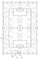
- FIG. 5 is a schematic plan view showing an example of a mode in which a plurality of physical cameras and a plurality of virtual cameras used in the image processing system according to the first and second embodiments are installed in a soccer field. It is a block diagram which shows an example of the hardware composition of the electric system of the image processing apparatus which concerns on 1st and 2nd Embodiment.
- FIG. 5 is a conceptual diagram showing an example of a plurality of captured images 46B in a time series constituting a physical camera moving image generated and output by the image processing apparatus according to the first and second embodiments. It is a block diagram which shows an example of the main part function of the image processing apparatus which concerns on 1st Embodiment. It is a conceptual diagram which shows an example of the processing content of the virtual viewpoint image generation part of the image processing apparatus which concerns on 1st Embodiment. It is a conceptual diagram which shows an example of the processing content of the output part of the image processing apparatus which concerns on 1st Embodiment.
- FIG. 14A It is a flowchart which shows an example of the flow of the output control processing which concerns on 1st Embodiment, and is the continuation of the flowchart shown in FIG. 14A. It is a conceptual diagram which shows an example of the mode of switching from the output of a reference physical camera image to the output of a virtual viewpoint image. It is a conceptual diagram which shows an example of the mode of switching from the output of a virtual viewpoint image to the output of a reference physical camera image.
- FIG. 5 is a conceptual diagram showing an example of a mode in which the output of a reference physical camera image is directly switched to the output of a virtual viewpoint image satisfying the best imaging conditions.
- FIG. 14A It is a continuation of the flowchart shown in FIG. 29A. It is a continuation of the flowchart shown in FIG. 29B.
- FIG. 29A It is a continuation of the flowchart shown in FIG. 29B.
- FIG. 29B It is a block diagram which shows an example of the mode in which the preliminary virtual viewpoint continuous shot image of a physical camera continuous shot image is stored in the storage as an image group. It is a block diagram which shows an example of a mode in which an output control program is installed in a computer of an image processing apparatus from a storage medium in which an output control program is stored.
- CPU is an abbreviation for "Central Processing Unit”.
- RAM is an abbreviation for "Random Access Memory”.
- SSD is an abbreviation for “Solid State Drive”.
- HDD is an abbreviation for “Hard Disk Drive”.
- EEPROM refers to the abbreviation of "Electrically Erasable and Programmable Read Only Memory”.
- I / F refers to the abbreviation of "Interface”.
- IC refers to the abbreviation of "Integrated Circuit”.
- ASIC refers to the abbreviation of "Application Specific Integrated Circuit”.
- PLD refers to the abbreviation of "Programmable Logic Device”.
- FPGA refers to the abbreviation of "Field-Programmable Gate Array”.
- SoC is an abbreviation for "System-on-a-chip".
- CMOS is an abbreviation for "Complementary Metal Oxide Semiconductor”.
- CCD refers to the abbreviation of "Charge Coupled Device”.
- EL refers to the abbreviation for "Electro-Luminescence”.
- GPU refers to the abbreviation of "Graphics Processing Unit”.
- WAN is an abbreviation for "Wide Area Network”.
- LAN is an abbreviation for "Local Area Network”.
- 3D refers to the abbreviation of "3 Dimensions”.
- USB is an abbreviation for "Universal Serial Bus”.
- 5G refers to the abbreviation for “5th Generation”.
- LTE is an abbreviation for “Long Term Evolution”.
- WiFi is an abbreviation for "Wireless Fidelity”.
- RTC is an abbreviation for "Real Time Clock”.
- SNMP is an abbreviation for "Simple Network Time Protocol”.
- NTP is an abbreviation for "Network Time Protocol”.
- GPS is an abbreviation for "Global Positioning System”. Exif is an abbreviation for "Exchangeable image file format for digital still cameras”.
- fps is an abbreviation for "frame per second”.
- GNSS is an abbreviation for "Global Navigation Satellite System”.
- a CPU is illustrated as an example of the “processor” according to the technology of the present disclosure, but the “processor” according to the technology of the present disclosure includes a plurality of processing devices such as a CPU and a GPU. It may be a combination of.
- the GPU operates under the control of the CPU and is responsible for executing image processing.
- match means, in addition to perfect match, an error generally allowed in the technical field to which the technology of the present disclosure belongs (to the extent that it does not contradict the purpose of the technology of the present disclosure). It refers to a match in terms of (meaning including error).
- the "same imaging time” has a meaning including an error generally allowed in the technical field to which the technology of the present disclosure belongs in addition to the completely same imaging time (in the present disclosure). It refers to the same imaging time (meaning including an error that does not go against the purpose of the technology).
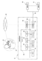
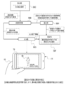
- the image processing system 10 includes an image processing device 12, a user device 14, and a plurality of physical cameras 16.
- the user device 14 is used by the user 18.
- a smartphone is applied as an example of the user device 14.
- the smartphone is merely an example, and may be, for example, a personal computer, a tablet terminal, or a portable multifunctional terminal such as a head-mounted display.
- a server is applied as an example of the image processing device 12.
- the number of servers may be one or a plurality.
- the server is merely an example, and may be, for example, at least one personal computer, or may be a combination of at least one server and at least one personal computer.
- the image processing device 12 may be at least one device capable of executing image processing.
- the network 20 is configured to include, for example, a WAN and / or a LAN.
- the network 20 includes, for example, a base station.
- the number of base stations is not limited to one, and there may be a plurality of base stations.
- the communication standards used in the base station include wireless communication standards such as 5G standard, LTE standard, WiFi (802.11) standard, and Bluetooth® standard.
- the network 20 establishes communication between the image processing device 12 and the user device 14, and transmits and receives various information between the image processing device 12 and the user device 14.
- the image processing device 12 receives a request from the user device 14 via the network 20, and provides a service according to the request to the requesting user device 14 via the network 20.
- the wireless communication method is applied as an example of the communication method between the user device 14 and the network 20 and the communication method between the image processing device 12 and the network 20.
- This is just an example, and a wired communication method may be used.
- the physical camera 16 actually exists as an object and is a visually recognizable imaging device.
- the physical camera 16 is an imaging device having a CMOS image sensor, and is equipped with an optical zoom function and / or a digital zoom function.
- CMOS image sensor instead of the CMOS image sensor, another type of image sensor such as a CCD image sensor may be applied.
- the zoom function is mounted on the plurality of physical cameras 16, but this is merely an example, and the zoom function may be mounted on a part of the plurality of physical cameras 16. However, the zoom function may not be mounted on the plurality of physical cameras 16.
- a plurality of physical cameras 16 are installed in the soccer field 22.
- the plurality of physical cameras 16 have different imaging positions (hereinafter, also simply referred to as “positions”), and the imaging direction (hereinafter, simply referred to as “direction”) of each physical camera 16 can be changed.
- positions also simply referred to as “positions”
- direction the imaging direction of each physical camera 16 can be changed.
- each of the plurality of physical cameras 16 is arranged so as to surround the soccer field 24, and an area including the soccer field 24 is imaged as an imaging area.
- the imaging by the physical camera 16 refers to, for example, imaging at an angle of view including an imaging region.
- imaging area includes the concept of an area showing a part of the soccer field 22 in addition to the concept of the area showing the whole in the soccer field 22.
- the imaging region is changed according to the imaging position, the imaging direction, and the angle of view.
- each of the plurality of physical cameras 16 is arranged so as to surround the soccer field 24
- the technique of the present disclosure is not limited to this, and for example, in the soccer field 24.
- a plurality of physical cameras 16 may be arranged so as to surround a specific part. The positions and / or orientations of the plurality of physical cameras 16 can be changed, and it is determined to be generated according to the virtual viewpoint image requested by the user 18 or the like.
- At least one physical camera 16 is installed in an unmanned aerial vehicle (for example, a multi-rotorcraft unmanned aerial vehicle), and a bird's-eye view of the area including the soccer field 24 as an imaging area from the sky. You may make an image with.
- an unmanned aerial vehicle for example, a multi-rotorcraft unmanned aerial vehicle
- a bird's-eye view of the area including the soccer field 24 as an imaging area from the sky You may make an image with.
- the image processing device 12 is installed in the control room 32.
- the plurality of physical cameras 16 and the image processing device 12 are connected via a LAN cable 30, and the image processing device 12 controls the plurality of physical cameras 16 and is imaged by each of the plurality of physical cameras 16. The image obtained by this is acquired.
- the connection using the wired communication method by the LAN cable 30 is illustrated here, the connection is not limited to this, and the connection using the wireless communication method may be used.
- the soccer stadium 22 is provided with spectator seats 26 so as to surround the soccer field 24, and the user 18 is seated in the spectator seats 26.
- the user 18 possesses the user device 14, which is used by the user 18. It should be noted that here, the example in which the user 18 exists in the soccer stadium 22 is described, but the technique of the present disclosure is not limited to this, and the user 18 is outside the soccer stadium 22. It may exist.
- the image processing device 12 acquires an image captured image 46B showing an image pickup region when observed from each position of the plurality of physical cameras 16 from each of the plurality of physical cameras 16.
- the captured image 46B is a frame image showing an imaging region when observed from the position of the physical camera 16. That is, the captured image 46B is obtained by capturing the imaging region by each of the plurality of physical cameras 16.
- the physical camera identification information that identifies the physical camera 16 used for imaging and the time when the image was taken by the physical camera 16 (hereinafter, also referred to as “physical camera imaging time”) are set for each frame. Has been granted.
- the captured image 46B is also provided with physical camera installation position information capable of specifying the installation position (imaging position) of the physical camera 16 used for imaging for each frame.
- the image processing device 12 generates an image using 3D polygons by synthesizing a plurality of captured images 46B obtained by capturing an imaging region by a plurality of physical cameras 16. Then, the image processing device 12 generates a virtual viewpoint image 46C indicating the imaging region when the imaging region is observed from an arbitrary position and an arbitrary direction, frame by frame, based on the image using the generated 3D polygon.
- the captured image 46B is an image obtained by being captured by the physical camera 16
- the virtual viewpoint image 46C is a virtual imaging device, that is, a virtual image from an arbitrary position and an arbitrary direction. It can be considered that the image is obtained by being imaged by the camera 42.
- the virtual camera 42 is a virtual camera that does not actually exist as an object and is not visually recognized.
- virtual cameras are installed at a plurality of locations in the soccer field 22 (see FIG. 3). All virtual cameras 42 are installed at different positions from each other. Further, all the virtual cameras 42 are installed at different positions from all the physical cameras 16. That is, all the physical cameras 16 and all the virtual cameras 42 are installed at different positions from each other.
- the virtual camera identification information that identifies the virtual camera 42 used for imaging and the time when the image is captured by the virtual camera 42 (hereinafter, also referred to as “virtual camera imaging time”) are set for each frame. Is given to. Further, the virtual viewpoint image 46C is provided with virtual camera installation position information capable of specifying the installation position (imaging position) of the virtual camera 42 used for imaging.
- camera installation position information when it is not necessary to distinguish between the physical camera installation position information and the virtual camera installation position information, it is referred to as "camera installation position information".
- the camera specific information, the imaging time, and the camera installation position information are added to each camera image by, for example, the Exif method.
- the image processing device 12 holds, for example, camera images for a predetermined time (for example, several hours to several tens of hours). Therefore, for example, the image processing device 12 acquires a camera image at a designated imaging time from a group of camera images for a predetermined time, and processes the acquired camera image.
- the position (hereinafter, also referred to as “virtual camera position”) 42A and the orientation (hereinafter, also referred to as “virtual camera orientation”) 42B of the virtual camera 42 can be changed.
- the angle of view of the virtual camera 42 can also be changed.
- the virtual camera position 42A is referred to in the first embodiment, the virtual camera position 42A is also generally referred to as a viewpoint position. Further, in the first embodiment, it is referred to as a virtual camera orientation 42B, but in general, the virtual camera orientation 42B is also referred to as a line-of-sight direction.
- the viewpoint position means, for example, the position of the viewpoint of a virtual person
- the line-of-sight direction means, for example, the direction of the line of sight of a virtual person.
- the virtual camera position 42A is used for convenience of explanation, but it is not essential to use the virtual camera position 42A.
- “Installing a virtual camera” means determining the viewpoint position, line-of-sight direction, and / or angle of view for generating the virtual viewpoint image 46C. Therefore, for example, the present invention is not limited to the mode in which an object such as a virtual camera is installed in the imaging region on a computer, and another method such as numerically specifying the coordinates and / or direction of the viewpoint position may be used.
- "capturing with a virtual camera” means generating a virtual viewpoint image 46C corresponding to the case where the imaging region is viewed from the position and direction in which the "virtual camera is installed".
- the virtual viewpoint image 46C a virtual viewpoint image showing an imaging area when the imaging area is observed from the virtual camera position 42A in the spectator seat 26 and the virtual camera orientation 42B is shown.
- the virtual camera position and virtual camera orientation are not fixed. That is, the virtual camera position and the virtual camera orientation can be changed according to an instruction from the user 18 or the like.
- the image processing device 12 sets the position of a person designated as a target subject (hereinafter, also referred to as “target person”) among soccer players and referees in the soccer field 24 as a virtual camera position, and sets the target person. It is also possible to set the line-of-sight direction as the direction of the virtual camera.
- virtual cameras 42 are installed at a plurality of locations in the soccer field 24 and at a plurality of locations around the soccer field 24.
- the installation mode of the virtual camera 42 shown in FIG. 3 is merely an example.
- the virtual camera 42 may not be installed in the soccer field 24 and the virtual camera 42 may be installed only around the soccer field 24, or the virtual camera 42 may not be installed around the soccer field 24 and the soccer may be installed.
- the virtual camera 42 may be installed only in the field 24.
- the number of virtual cameras 42 installed may be larger or smaller than the example shown in FIG.
- the virtual camera position 42A and the virtual camera orientation 42B of each of the virtual cameras 42 can also be changed.
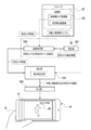
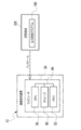
- the image processing device 12 includes a computer 50, an RTC 51, a reception device 52, a display 53, a first communication I / F 54, and a second communication I / F 56.
- the computer 50 includes a CPU 58, a storage 60, and a memory 62.
- the CPU 58 is an example of a "processor” according to the technique of the present disclosure.
- the memory 62 is an example of a “memory” according to the technique of the present disclosure.
- the computer 50 is an example of a "computer” according to the technique of the present disclosure.
- the CPU 58, the storage 60, and the memory 62 are connected via the bus 64.
- the bus 64 In the example shown in FIG. 4, one bus is shown as the bus 64 for convenience of illustration, but a plurality of buses may be used. Further, the bus 64 may include a serial bus or a parallel bus composed of a data bus, an address bus, a control bus, and the like.
- the CPU 58 controls the entire image processing device 12.
- the storage 60 stores various parameters and various programs.
- the storage 60 is a non-volatile storage device.
- EEPROM is applied as an example of the storage 60.
- the memory 62 is a storage device. Various information is temporarily stored in the memory 62.
- the memory 62 is used as a work memory by the CPU 58.
- RAM is applied as an example of the memory 62.
- the RTC 51 receives drive power from a power supply system disconnected from the power supply system for the computer 50, and continues to tick the current time (for example, year, month, day, hour, minute, second) even when the computer 50 is shut down.
- the RTC 51 outputs the current time to the CPU 58 each time the current time is updated.
- the CPU 58 uses the current time input from the RTC 51 as the imaging time.
- an example in which the CPU 58 acquires the current time from the RTC 51 is given, but the technique of the present disclosure is not limited to this.
- the CPU 58 is provided from an external device (not shown) via the network 20.
- the current time may be acquired (for example, by using SNMP and / or NTP), or the current time may be acquired from a built-in or connected GNSS device (for example, GPS device). You may.
- the reception device 52 receives instructions from the user of the image processing device 12 and the like. Examples of the reception device 52 include a touch panel, hard keys, a mouse, and the like.
- the reception device 52 is connected to a bus 64 or the like, and the instruction received by the reception device 52 is acquired by the CPU 58.
- the display 53 is connected to the bus 64 and displays various information under the control of the CPU 58.
- An example of the display 53 is a liquid crystal display.
- another type of display such as an EL display (for example, an organic EL display or an inorganic EL display) may be adopted as the display 53.
- the first communication I / F 54 is connected to the LAN cable 30.
- the first communication I / F 54 is realized, for example, by a device having an FPGA.
- the first communication I / F 54 is connected to the bus 64 and controls the exchange of various information between the CPU 58 and the plurality of physical cameras 16.
- the first communication I / F 54 controls a plurality of physical cameras 16 according to the request of the CPU 58.
- the first communication I / F 54 acquires the captured image 46B (see FIG. 2) obtained by being imaged by each of the plurality of physical cameras 16, and outputs the acquired captured image 46B to the CPU 58.
- the first communication I / F 54 is exemplified as a wired communication I / F here, it may be a wireless communication I / F such as a high-speed wireless LAN.
- the second communication I / F 56 is connected to the network 20 so as to be capable of wireless communication.
- the second communication I / F56 is realized, for example, by a device having an FPGA.
- the second communication I / F 56 is connected to the bus 64.
- the second communication I / F 56 manages the exchange of various information between the CPU 58 and the user device 14 in a wireless communication system via the network 20.
- At least one of the first communication I / F54 and the second communication I / F56 can be configured by a fixed circuit instead of the FPGA. Further, at least one of the first communication I / F54 and the second communication I / F56 may be a circuit composed of an ASIC, an FPGA, and / or a PLD or the like.
- the user device 14 includes a computer 70, a gyro sensor 74, a reception device 76, a display 78, a microphone 80, a speaker 82, a physical camera 84, and a communication I / F 86.
- the computer 70 includes a CPU 88, a storage 90, and a memory 92, and the CPU 88, the storage 90, and the memory 92 are connected via a bus 94.
- one bus is shown as the bus 94 for convenience of illustration, but the bus 94 may be composed of a serial bus, or may be a data bus, an address bus, a control bus, or the like. Is configured to include.
- the CPU 88 controls the entire user device 14.
- the storage 90 stores various parameters and various programs.
- the storage 90 is a non-volatile storage device.
- EEPROM is applied as an example of the storage 90.
- this is just an example, and may be SSD, HDD, or the like.
- Various information is temporarily stored in the memory 92, and the memory 92 is used as a work memory by the CPU 88.
- RAM is applied as an example of the memory 92.
- the gyro sensor 74 includes an angle around the yaw axis of the user device 14 (hereinafter, also referred to as “yaw angle”), an angle around the roll axis of the user device 14 (hereinafter, also referred to as “roll angle”), and the user device 14.
- the angle around the pitch axis (hereinafter, also referred to as “pitch angle”) is measured.
- the gyro sensor 74 is connected to the bus 94, and the angle information indicating the yaw angle, the roll angle, and the pitch angle measured by the gyro sensor 74 is acquired by the CPU 88 via the bus 94 or the like.
- the reception device 76 receives an instruction from the user 18 (see FIGS. 1 and 2). Examples of the reception device 76 include a touch panel 76A, a hard key, and the like. The reception device 76 is connected to the bus 94, and the instruction received by the reception device 76 is acquired by the CPU 88.
- the display 78 is connected to the bus 94 and displays various information under the control of the CPU 88.
- An example of the display 78 is a liquid crystal display.
- another type of display such as an EL display (for example, an organic EL display or an inorganic EL display) may be adopted as the display 78.
- the user device 14 includes a touch panel display, and the touch panel display is realized by the touch panel 76A and the display 78. That is, the touch panel display is formed by superimposing the touch panel 76A on the display area of the display 78, or by incorporating a touch panel function (“in-cell” type) inside the display 78.
- the "in-cell” type touch panel display is merely an example, and may be an "out-sel” type or "on-cell” type touch panel display.
- the microphone 80 converts the collected sound into an electric signal.
- the microphone 80 is connected to the bus 94.
- the electric signal obtained by converting the sound collected by the microphone 80 is acquired by the CPU 88 via the bus 94.
- the speaker 82 converts an electric signal into sound.
- the speaker 82 is connected to the bus 94.
- the speaker 82 receives the electric signal output from the CPU 88 via the bus 94, converts the received electric signal into sound, and outputs the sound obtained by converting the electric signal to the outside of the user device 14.
- the physical camera 84 acquires an image showing the subject by taking an image of the subject.
- the physical camera 84 is connected to the bus 94.
- the image obtained by capturing the subject by the physical camera 84 is acquired by the CPU 88 via the bus 94.
- the image obtained by being captured by the physical camera 84 may also be used together with the captured image 46B to generate the virtual viewpoint image 46C.
- the communication I / F86 is connected to the network 20 so as to be capable of wireless communication.
- Communication I / F86 is realized, for example, by a device composed of circuits (eg, ASIC, FPGA, and / or PLD, etc.).
- the communication I / F86 is connected to the bus 94.
- the communication I / F86 controls the exchange of various information between the CPU 88 and the external device by a wireless communication method via the network 20.
- Examples of the "external device" include an image processing device 12.
- Each of the plurality of physical cameras 16 (see FIGS. 1 to 4) generates a moving image (hereinafter, also referred to as “physical camera moving image”) indicating the imaging region by imaging the imaging region.
- a moving image hereinafter, also referred to as “physical camera moving image”
- any one of the plurality of physical cameras 16 is used as the reference physical camera.
- the physical camera moving image obtained by being captured by the reference physical camera (hereinafter, also referred to as “reference physical camera moving image”) is delivered to the user device 14, and is displayed on the display 78 of the user device 14, for example. NS. Then, the user 18 appreciates the reference physical camera moving image displayed on the display 78.
- the physical camera moving image is obtained by being captured by the physical camera 16 at a specific frame rate (for example, 60 fps).
- a specific frame rate for example, 60 fps.
- the physical camera moving image is a multi-frame image composed of a plurality of frames obtained according to a specific frame rate. That is, the physical camera moving image is configured by arranging a plurality of captured images 46B obtained at each timing defined at a specific frame rate in chronological order.
- the target person is an example of the "object” according to the technique of the present disclosure
- the target person image 96 is an example of the "object image” according to the technique of the present disclosure.
- the captured images 46B1 to 46B3 for three frames are roughly classified into the captured image 46B1 of the first frame, the captured image 46B2 of the second frame, and the captured image 46B3 of the third frame from the oldest frame to the latest frame. ..
- the entire target person image 96 appears at a position that can be visually recognized including the facial expression of the target person.
- the captured image 46B2 of the second frame and the captured image 46B3 of the third frame most of the area including the face of the target person in the target person image 96 cannot be visually recognized by the person image showing the person other than the target person. It has been blocked by the level.
- the physical camera moving image shown in FIG. 6 is displayed on the display 78 of the user device 14 as the reference physical camera moving image
- the user 18 has the target person image 96 from the captured images 46B2 and 46B3 of at least the second and third frames. It becomes difficult to grasp the whole aspect of.
- the facial expression of the target person cannot be observed from at least the captured images 46B2 and 46B3 of the second and third frames. ..
- the output control program 100 is stored in the storage 60. Then, the CPU 58 executes the output control process (FIGS. 14A and 14B) described later according to the output control program 100.
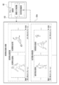
- the CPU 58 reads the output control program 100 from the storage 60 and executes the output control program 100 on the memory 62 to perform the virtual viewpoint image generation unit 58A, the image acquisition unit 58B, the detection unit 58C, the output unit 58D, and the image selection. Operates as part 58E.
- the image group 102 is stored in the storage 60.
- the image group 102 includes a physical camera moving image and a virtual viewpoint moving image.
- the physical camera moving image is roughly divided into a reference physical camera moving image and another physical camera moving image obtained by being captured by a physical camera 16 (hereinafter, also referred to as “other physical camera”) other than the reference physical camera. Will be done.
- the reference physical camera moving image includes a plurality of captured images 46B obtained by being captured by the reference physical camera as reference physical camera images in chronological order.
- the moving image of the other physical camera includes a plurality of captured images 46B obtained by being captured by the other physical camera in chronological order as images of the other physical camera.
- the virtual viewpoint moving image is obtained by being captured by the virtual camera 42 (see FIGS. 2 and 3) at a specific frame rate.
- the virtual viewpoint moving image is a multi-frame image composed of a plurality of frames obtained according to a specific frame rate. That is, the virtual viewpoint moving image is configured by arranging a plurality of virtual viewpoint images 46C obtained at each timing defined at a specific frame rate in chronological order.
- a plurality of virtual cameras 42 exist, and each virtual camera 42 obtains a virtual viewpoint moving image and stores it in the storage 60.
- a camera image obtained by taking an image with a camera other than the reference physical camera will be referred to as an "other camera image”. That is, the other camera image is a general term for the other physical camera image and the virtual viewpoint image.
- the detection unit 58C performs the detection process.
- the detection process is a process of detecting a target person image 96 from each of a plurality of camera images obtained by being imaged by a plurality of cameras having different positions.
- the target person image 96 is detected by detecting the face image showing the face of the target person. Examples of the detection process include a first detection process (see FIG. 11) described later and a second detection process (see FIG. 12) described later.
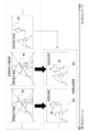
- the output unit 58D outputs a reference physical camera image among a plurality of camera images. Further, when the output unit 58D transitions from the detection state in which the target person image 96 is detected from the reference physical camera image by the detection process to the non-detection state in which the target person image 96 is not detected from the reference physical camera image by the detection process. , Of the plurality of camera images, the other camera image in which the target person image 96 is detected by the detection process is output. For example, the output unit 58D switches from the output of the reference physical camera image to the output of another camera image when the state transitions from the detection state to the non-detection state while the reference physical camera image is being output.
- the transition from the detection state to the non-detection state means that the reference physical camera image to be output by the output unit 58D does not include the target person from the reference physical camera image in which the target person is captured. It means to switch to the reference physical camera image.
- the transition from the detected state to the non-detected state means that the target person is captured between frames that are temporally adjacent to each other among a plurality of reference physical camera images included in the reference physical camera moving image. This means that the output target by the output unit 58D is switched from the existing frame to the frame in which the target person is not reflected.
- an object in the imaging region (for example, a target person or an object around the target person, etc.) as shown in the captured images 46B1 to 46B2 shown in FIG. ) Moves from a state in which the target person image 96 can be detected to a state in which it is hidden by another person or the like and cannot be detected.
- the camera image is an example of the "image” according to the technique in the present disclosure.
- the reference physical camera image is an example of the "first image” according to the technique of the present disclosure.
- the other camera image is an example of the "second image” according to the technique of the present disclosure.
- the virtual viewpoint image generation unit 58A generates a plurality of virtual viewpoint moving images by causing each of all the virtual cameras 42 to take an image.
- the virtual viewpoint image generation unit 58A acquires a physical camera moving image from the storage 60.
- the virtual viewpoint image generation unit 58A is based on the physical camera moving image acquired from the storage 60, and the virtual viewpoint moving image according to the virtual camera position, the virtual camera orientation, and the angle of view currently set for each virtual camera 42. Generate an image.
- the virtual viewpoint image generation unit 58A stores the generated virtual viewpoint moving image in the storage 60 in units of the virtual cameras 42.
- the virtual camera position, the virtual camera orientation, and the virtual viewpoint moving image according to the angle of view that are set at the present time are, for example, from the virtual camera position and the virtual camera orientation that are set at the present time. It means a moving image showing the observed area at the angle of view set in.
- the virtual viewpoint image generation unit 58A generates a plurality of virtual viewpoint moving images by causing each of all the virtual cameras 42 to take an image is given, but not all virtual viewpoint images are necessarily generated. It is not necessary to have each of the cameras 42 perform imaging, and for example, depending on the performance of a computer or the like, it may be possible that some virtual cameras 42 do not generate a virtual viewpoint moving image.
- the output unit 58D acquires the reference physical camera moving image from the storage 60 and outputs the acquired reference physical camera moving image to the user device 14. As a result, the reference physical camera moving image is displayed on the display 78 of the user device 14.
- the user 18 sets the area of interest (hereinafter, also referred to as “attention area”) on the touch panel 76A. Specify with your finger via.
- the region of interest is the region including the target person image 96 in the reference physical camera moving image displayed on the display 78.
- the user device 14 transmits the attention area information indicating the attention area in the reference physical camera moving image to the image acquisition unit 58B.
- the image acquisition unit 58B receives the attention area information transmitted from the user device 14.
- the image acquisition unit 58B performs image analysis (for example, image analysis by a cascade classifier and / or pattern matching, etc.) on the received attention area information, and from the attention area indicated by the attention area information, the target person image. 96 is extracted.
- the image acquisition unit 58B stores the target person image 96 extracted from the region of interest as the target person image sample 98 in the storage 60.
- the image acquisition unit 58B acquires the reference physical camera image in units of one frame from the reference physical camera moving image in the storage 60.
- the detection unit 58C executes the first detection process.
- the reference physical camera image acquired by the image acquisition unit 58B is subjected to image analysis using the target person image sample 98 in the storage 60, so that the target person image 96 is obtained from the reference physical camera image.
- Examples of the image analysis include image analysis by a cascade classifier and / or pattern matching and the like.
- the target person image 96 detected by the first detection process also includes an image showing a target person having a mode different from that of the target person shown by the target person image 96 shown in FIG. That is, the detection unit 58C determines whether or not the target person indicated by the target person image sample 98 is reflected in the reference physical camera image by executing the first detection process.
- the output unit 58D uses the reference physical camera image processed by the first detection process, that is, the reference physical camera image including the target person image 96 as a user device. Output to 14. As a result, the reference physical camera image including the target person image 96 is displayed on the display 78 of the user device 14.
- the image acquisition unit 58B has the same imaging time as the reference physical camera image processed by the first detection process. Acquire a plurality of other camera images from the storage 60. In the following, for convenience of explanation, a plurality of other camera images will also be referred to as "other camera image group".
- the detection unit 58C executes the second detection process for each of the other camera images included in the other camera image group acquired by the image acquisition unit 58B.
- the second detection process differs from the first detection process in that another camera image is used as a processing target instead of the reference physical camera image.
- the image selection unit 58E selects the image selection unit 58E from the other camera image group including the target person image 96 detected by the second detection process. Select another camera image that meets the best imaging conditions.
- the best imaging condition is, for example, that the position of the target person image 96 in the other camera image is within the predetermined range and the size of the target person image 96 in the other camera image is within the predetermined range. Refers to the condition that the size is larger than the default size.
- the best imaging condition the condition that the entire target person shown by the target person image 96 is most reflected in the predetermined central frame in the central portion of the frame is used. ing.
- the shape and / or size of the central frame may be fixed or may be changed according to given instructions and / or conditions.
- the frame is not limited to the central frame, and a frame may be provided at another position.
- condition that the entire target person is reflected in the central frame is illustrated, but this is just an example, and the face of the target person is included in the central frame. It may be a condition that an area of a predetermined ratio (for example, 80%) or more is reflected.
- the default ratio may be a fixed value or a variable value that is changed according to a given instruction and / or condition.
- the image selection unit 58E selects and selects other camera images that satisfy the best imaging conditions from the other camera image group including the target person image 96 detected by the second detection process.
- the camera image is output to the output unit 58D.
- the detection unit 58C outputs the other camera image in which the target person image 96 is detected to the output unit 58D. ..
- the output unit 58D outputs another camera image input from the detection unit 58C or the image selection unit 58E to the user device 14. As a result, another camera image including the target person image 96 is displayed on the display 78 of the user device 14.
- the output unit 58D uses the user device 14 as a reference physical camera image to be processed by the first detection process. Output to. In this case, the reference physical camera image in which the target person image 96 is not detected by the first detection process is output to the user device 14. As a result, the display 78 of the user device 14 displays the reference physical camera image in which the target person image 96 was not detected by the first detection process.
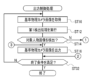
- FIGS. 14A and 14B show an example of the flow of output control processing executed by the CPU 58.
- the flow of the output control process shown in FIGS. 14A and 14B is an example of the "image processing method" according to the technique of the present disclosure.
- the description of the output control process shown below is based on the premise that the image group 102 is already stored in the storage 60 for convenience of explanation. Further, the description of the output control process shown below is based on the premise that the target person image sample 98 is already stored in the storage 60 for convenience of explanation.
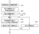
- step ST10 the image acquisition unit 58B acquires an unprocessed reference physical camera image for one frame from the reference physical camera moving image in the storage 60, and then outputs the image.
- the control process proceeds to step ST12.
- the unprocessed reference physical camera image refers to a reference physical camera image that has not yet been processed in step ST12.
- step ST12 the detection unit 58C executes the first detection process on the reference physical camera image acquired in step ST10, and then the output control process shifts to step ST14.
- step ST14 the detection unit 58C determines whether or not the target person image 96 is detected from the reference physical camera image by the first detection process. In step ST14, if the target person image 96 is not detected from the reference physical camera image by the first detection process, the determination is denied and the output control process shifts to step ST18 shown in FIG. 14B. When the target person image 96 is detected from the reference physical camera image by the first detection process in step ST14, the determination is affirmed and the output control process shifts to step ST16.
- step ST16 the output unit 58D outputs the reference physical camera image processed by the first detection process of step ST14 to the user device 14, and then the output control process shifts to step ST32.
- the reference physical camera image is output to the user device 14 by executing the process of step ST16, the reference physical camera image is displayed on the display 78 of the user device 14 (see FIG. 11).
- step ST18 shown in FIG. 14B the image acquisition unit 58B acquires another camera image group having the same imaging time as the reference physical camera image processed by the first detection process from the storage 60, and then outputs control process. Moves to step ST20.
- step ST20 the detection unit 58C executes the second detection process on the other camera image group acquired in step ST18, and then the output control process shifts to step ST22.
- step ST22 the detection unit 58C determines whether or not the target person image 96 is detected from the other camera image group acquired in step ST18. If the target person image 96 is not detected from the other camera image group acquired in step ST22 in step ST22, the determination is denied and the output control process shifts to step ST16 shown in FIG. 14A. In step ST22, when the target person image 96 is detected from the other camera image group acquired in step ST18, the determination is affirmed, and the output control process shifts to step ST24.
- step ST24 the detection unit 58C determines whether or not there are a plurality of other camera images in which the target person image 96 is detected by the second detection process. In step ST24, when there are a plurality of other camera images in which the target person image 96 is detected by the second detection process, the determination is affirmed and the output control process shifts to step ST26. In step ST24, if the other camera image in which the target person image 96 is detected by the second detection process is one frame, the determination is denied and the output control process shifts to step ST30.
- step ST26 the image selection unit 58E selects another camera image satisfying the best imaging conditions (see FIG. 12) from the other camera image group in which the target person image 96 is detected by the second detection process, and then outputs control. The process proceeds to step ST28.
- step ST28 the output unit 58D outputs the other camera image selected in step ST26 to the user device 14, and then the output control process shifts to step ST32 shown in FIG. 14A.
- the other camera image is output to the user device 14 by executing the process of step ST28, the other camera image is displayed on the display 78 of the user device 14 (see FIG. 13).
- step ST30 the output unit 58D outputs another camera image in which the target person image 96 is detected by the second detection process to the user device 14, and then the output control process shifts to step ST32 shown in FIG. 14A.
- the other camera image is output to the user device 14 by executing the process of step ST30, the other camera image is displayed on the display 78 of the user device 14 (see FIG. 13).
- step ST32 shown in FIG. 14A the output unit 58D determines whether or not the condition for terminating the output control process (hereinafter, also referred to as “output control process end condition”) is satisfied.
- the output control processing end condition there is a condition that the image processing apparatus 12 is instructed to end the output control process.
- the instruction to end the output control process is received by, for example, the receiving device 52 or 76. If the output control process end condition is not satisfied in step ST32, the determination is denied and the output control process shifts to step ST10. If the output control process end condition is satisfied in step ST32, the determination is affirmed and the output control process ends.
- the reference physical camera image in which the target person image 96 is not obstructed by obstacles is output to the user device 14 by the output unit 58D.
- the entire target person image 96 is visually recognized instead of the reference physical camera image in which the target person image 96 is obstructed by the obstacle.
- a possible virtual viewpoint image 46C is output to the user device 14 by the output unit 58D. As a result, it is possible to continuously provide the user 18 with a camera image capable of observing the target person.
- the target person image 96 is blocked by an obstacle in the reference physical camera image under the condition that the reference physical camera moving image is output.
- the output of the reference physical camera moving image is switched to the output of the virtual viewpoint moving image.
- the output unit 58D reaches a state in which the target person image 96 is blocked by an obstacle in the reference physical camera image. Switch from the output of the reference physical camera moving image to the output of the virtual viewpoint moving image. Then, the output unit 58D ends the output of the virtual viewpoint moving image at a timing after the timing when the target person image 96 reaches the state of being blocked by the obstacle in the reference physical camera image. That is, the output of the virtual viewpoint moving image ends at a timing after the timing at which the target person image 96 is not detected by the first detection process. As a result, it is possible to provide the user 18 with a virtual viewpoint moving image capable of observing the target person after the target person image 96 is not detected by the first detection process.
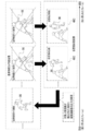
- the target person image 96 is blocked by an obstacle in the reference physical camera image, and then the target person image 96 is included in the reference physical camera image.
- the output unit 58D restarts the output of the reference physical camera moving image on condition that the camera returns to a state where it is not blocked by an obstacle. That is, the virtual viewpoint is provided on the condition that the target person image 96 is not detected from the reference physical camera image by the first detection process and the target person image 96 is detected from the reference physical camera image by the first detection process.
- the output of the moving image can be switched to the output of the moving image of the reference physical camera.
- the target person image 96 is not blocked by the obstacle in the reference physical camera image, the target person image 96 is not blocked by the obstacle in the reference physical camera image. Compared with the case where the output of the virtual viewpoint moving image is continued, it is possible to reduce the trouble of switching from the output of the virtual viewpoint moving image to the output of the reference physical camera moving image.
- the target person image 96 is detected by detecting the face image showing the face of the target person by the first detection process and the second detection process. Therefore, the target person image 96 can be detected with higher accuracy than the case where the face image is not detected.
- a plurality of frame images composed of a plurality of frames are output to the user device 14 by the output unit 58D.
- Examples of the multi-frame image include a reference physical camera moving image and a virtual viewpoint moving image as shown in FIGS. 15 and 16. Therefore, according to this configuration, the user 18 who is viewing the reference physical camera moving image and the virtual viewpoint moving image can continuously observe the target person.
- the imaging area is imaged by the plurality of physical cameras 16, and the imaging area is also imaged by the plurality of virtual cameras 42. Therefore, as compared with the case where the imaging region is imaged only by the physical camera 16 without using the virtual camera 42, the user 18 can observe the target person from various positions and directions.
- a plurality of physical cameras 16 and a plurality of virtual cameras 42 are illustrated, but the technique of the present disclosure is not limited to this, and the number of physical cameras 16 may be one, or the virtual cameras 42. The number of units may be one.
- the output of the virtual viewpoint moving image has been described with reference to a form example in which the output of the virtual viewpoint moving image is terminated at a timing after the timing at which the target person image 96 is not detected by the first detection process.
- the technology of the present disclosure is not limited to this.
- the output unit 58D outputs the virtual viewpoint moving image. May be started from a timing before the timing at which the target person image 96 is not detected by the first detection process.
- the timing at which the target person image 96 is not detected in the reference physical camera moving image can be recognized, so that the target person image 96 is not detected in the reference physical camera moving image. It is possible to output a virtual viewpoint moving image before the timing. As a result, it is possible to provide the user 18 with a virtual viewpoint moving image capable of observing the target person before the target person image 96 is not detected by the first detection process.
- the first embodiment when there are a plurality of other camera images in which the target person image 96 is detected by the second detection process, another camera image satisfying the best imaging conditions is output. As mentioned above, it is not always necessary to output other camera images that satisfy the best imaging conditions. For example, if any other camera image in which the target person image 96 is detected is output, the user 18 can visually recognize the target person image 96.
- the position of the target person image 96 in the other camera image group is within the predetermined range, and the position in the other camera image is within the predetermined range.
- the best imaging condition is that the position of the target person image 96 in the other camera image is within the predetermined range in the other camera image group, or the target person image 96 in the other camera image. It may be a condition that the size is larger than the default size.
- the output of the reference physical camera image can be directly switched to the output of the virtual viewpoint image 46C that satisfies the best imaging condition.
- the techniques of the present disclosure are not limited to this. If the output of the reference physical camera image is directly switched to the output of the virtual viewpoint image 46C that satisfies the best imaging conditions, it may be difficult to grasp the position of the target person before and after the output is switched.
- the output unit 58D continuously changes the position, orientation, and angle of view during the period of switching from the output of the reference physical camera image to the output of the virtual viewpoint image 46C that satisfies the best imaging condition.
- the camera image obtained by being imaged by a plurality of connected cameras is output.
- the camera image obtained by being captured by a plurality of cameras that continuously connect the position, orientation, and angle of view is, for example, the best imaging condition from the imaging position, imaging direction, and angle of view of the reference physical camera.
- the target person image 96 when the target person image 96 is obstructed by an obstacle in the reference physical camera image, the target person image 96 is replaced with the reference physical camera image obstructed by the obstacle.
- a form example in which a virtual viewpoint image 46C or another physical camera image in which the entire target person image 96 can be visually recognized can be output to the user device 14 by the output unit 58D has been described.
- the entire target person image 96 is replaced with the reference physical camera image in which the target person image 96 is obstructed by the obstacle. Only the visible virtual viewpoint image 46C may be output.
- the user 18 can be provided with the virtual viewpoint moving image to continue observing the target person.
- the viewpoint image 46C or another physical camera image may be output.
- This particular part may be configurable according to instructions given by the user 18. For example, when the face indicated by the target person image 96 is set according to the instruction given by the user 18, the virtual viewpoint image 46C or another physical camera image in which the face of the target person can be visually recognized is output. Further, for example, the virtual viewpoint image 46C or another physical camera image in which the target person image 96 can be visually recognized may be output at a ratio larger than the ratio of the target person image 96 that can be visually recognized in the reference physical camera image.
- the image in which the target person image 96 is detected by the above detection process does not necessarily have to be output.
- the three-dimensional position of each object in the imaging region is recognized by triangulation or the like and the target person image 96 is obstructed by an obstacle in the reference physical camera image, the target person, the obstacle, and other objects.
- the virtual viewpoint image 46C showing the mode observed from the viewpoint position, direction, and angle of view estimated to be visible to the target person may be output from the positional relationship of the above.
- the detection process in the technique of the present disclosure also includes a process based on such estimation.
- a reference virtual viewpoint moving image composed of a plurality of time-series virtual viewpoint images 46C obtained by being imaged by a specific virtual camera 42 instead of the reference physical camera moving image. May be output to the user device 14 by the output unit 58D.
- the output of the reference virtual viewpoint moving image is switched to the output of another camera image (in the example shown in FIG. 19, a virtual viewpoint moving image other than the reference virtual viewpoint moving image). In this way, even when the output of the reference virtual viewpoint moving image can be switched to the output of the other camera image, the target person is continuously observed for the user 18 as in the first embodiment. Can be made to.
- the physical camera image and the virtual viewpoint image 46C have been described with reference to a form example in which the physical camera image and the virtual viewpoint image 46C are selectively output by the output unit 58D.
- the output is switched. Regardless of whether it is before or after, only the virtual viewpoint image 46C may be output by the output unit 58D. In this case as well, the user 18 can be made to continuously observe the target person as in the first embodiment.
- a bird's-eye view image including the target person image 96 may be output to the user device 14 by the output unit 58D as another camera image.
- the bird's-eye view image refers to an image showing a bird's-eye view of the imaging region (in the example shown in FIG. 20, the entire soccer field 24).
- the output unit 58D outputs a bird's-eye view image. It may be done. Therefore, according to the form example in which the bird's-eye view image is output by the output unit 58D, the target person is reflected as compared with the case where the camera image obtained by capturing only a part of the imaging region is output. It is possible to provide the user 18 with a camera image that is likely to be present.
- the reference physical camera moving image may be an image for television broadcasting.
- the image for television broadcasting include a recorded moving image or a moving image for live broadcasting.
- the image is not limited to a moving image, and may be a still image.
- the target person image 96 is blocked by an obstacle in the television broadcast image.
- a usage method is assumed in which a virtual viewpoint image 46C or another physical camera image in which the target person image 96 can be visually recognized is output to the user device 14 by using the technique described in the first embodiment. Therefore, according to the embodiment in which the image for television broadcasting is used as the reference physical camera moving image, even when the user 18 is viewing the image for television broadcasting, the target person is referred to the user 18 with respect to the user 18. It can be observed continuously.
- the installation position of the reference physical camera is not particularly determined, but the reference physical camera is an observation position for observing an imaging region (for example, a soccer field 24) among a plurality of physical cameras 16. Or, it is preferable that the physical camera 16 is installed in the vicinity of the observation position.
- the reference virtual viewpoint moving image is output by the output unit 58D instead of the reference physical camera moving image, it is installed at the observation position for observing the imaging area (for example, the soccer field 24) or near the observation position.
- the imaging region may be imaged by the virtual camera 42.
- the observation position for example, the position of the user 18 seated in the spectator seat 26 shown in FIG. 1 can be mentioned.
- the camera installed near the observation position for example, the camera installed at the position closest to the user 18 seated in the spectator seat 26 shown in FIG. 1 (for example, the physical camera 16 or the virtual camera 42). Can be mentioned.
- the user 18 views a camera image obtained by being imaged by an observation position for observing an imaging area or a camera installed in the vicinity of the observation position among a plurality of cameras. Even if there is, the user 18 can be made to continuously observe the target person.
- the reference physical camera is capturing the same region as or close to the region that the user 18 is viewing. Therefore, when the user 18 is directly looking at the imaging region (when directly observing in the real space), it can be detected from the reference physical camera moving image that the target person cannot be seen by the user 18.
- the virtual viewpoint image 46C or another physical camera image in which the target person image 96 can be visually recognized can be output to the user device 14.
- the target person when the state in which the target person image 96 is detected by the first detection process is changed to the state in which the target person image 96 is not detected, the target person is output from the output of the reference physical camera moving image.
- the technique of the present disclosure is not limited to this. For example, as shown in FIG. 21, even when the state in which the target person image 96 is detected by the first detection process is changed to the state in which the target person image 96 is not detected, the output unit 58D is still a reference physical camera.
- the output of the moving image may be continued, and the virtual viewpoint moving image capable of observing the target person image 96 may be output in parallel.
- the reference physical camera moving image and the virtual viewpoint moving image are displayed in parallel on the display 78 of the user device 14 which is the output destination of the camera image on different screens.
- the user 18 can continuously observe the target person through the reference physical camera moving image and the virtual viewpoint moving image while viewing the reference physical camera moving image.
- the reference virtual viewpoint moving image may be output to the user device 14 by the output unit 58D.
- another physical camera moving image may be output to the user device 14 by the output unit 58D.
- the reference physical camera moving image and the virtual viewpoint moving image are output to separate user devices 14 (one unit is not shown). You may do so.
- the target person image 96 is illustrated, but the technique of the present disclosure is not limited to this, and an image showing a non-person (object other than a human) may be used.
- a non-person a robot equipped with a device capable of recognizing an object (for example, a physical camera and a device including a computer connected to the physical camera) (for example, a robot that imitates a living thing such as a person, an animal, or an insect). , Animals, insects and the like.
- the other camera image including the target person image 96 is output by the output unit 58D, but the second embodiment does not include the target person image 96 depending on the conditions.
- An example of a form in which another camera image is also output by the output unit 58D will be described.
- the same components as those in the first embodiment are designated by the same reference numerals, and the description thereof will be omitted.
- the second embodiment a part different from the first embodiment will be described. Further, in the following, for convenience of explanation, when it is not necessary to distinguish between the moving image of another physical camera and the moving image of the virtual viewpoint, the moving image of another camera is referred to as a moving image of another camera.
- any one camera other than the reference physical camera among the plurality of cameras is regarded as a specific camera, and among the plurality of cameras, the reference physical camera and Cameras other than the specific camera are regarded as non-specific cameras.
- An example of the specific camera is a camera used in imaging for obtaining another camera image output by the output unit 58D by executing the process of step ST28 or step ST30 shown in FIG. 14B.
- the specific camera is an example of the "second image camera" according to the technique of the present disclosure.
- a third detection process and a fourth detection process are performed.
- the third detection process is a process of detecting the target person image 96 from the specific camera image which is another camera image obtained by being imaged by the specific camera.
- the specific camera image is an example of a "second image" according to the technique of the present disclosure.
- the target person image 96 is detected by detecting the face image showing the face of the target person.
- the other camera image that is the detection target of the face image is a specific camera image.
- the types of a plurality of frames constituting the other camera moving image obtained by being captured by the specific camera are the detection frame in which the target person image 96 is detected by the third detection process and the target person image by the third detection process. 96 is roughly classified into undetected frames that have not been detected.
- another camera moving image obtained by being captured by a specific camera is also referred to as a “specific camera moving image”.
- the fourth detection process is a process of detecting the target person image 96 from the non-specific camera image which is another camera image obtained by being imaged by the non-specific camera.
- the non-specific camera image in which the target person image 96 is detected by the fourth detection process is an example of the “third image” according to the technique of the present disclosure.
- the non-specific camera used in the imaging for obtaining the non-specific camera image in which the target person image 96 is detected by the fourth detection process is an example of the "third image camera” according to the technique of the present disclosure.
- the target person image 96 is detected by detecting the face image showing the face of the target person.
- the camera image to be detected of the face image is a non-specific camera image.
- the CPU 58 when the specific camera moving image includes a detection frame and a non-detection frame, the CPU 58 describes the distance between the position of the specific camera and the position of the non-specific camera, and the first embodiment.
- the non-detection frame and the non-specific camera image are selectively output according to the time of the non-detection state.
- the CPU 58 does not detect when the distance between the position of the specific camera and the position of the non-specific camera exceeds the threshold value and satisfies the non-detection frame output condition that the non-detection state time is less than the predetermined time.
- a frame is output, and when the non-detection frame output condition is not satisfied, a non-specific camera image is output instead of the non-detection frame.
- the CPU 58 of the image processing device 12 As shown in FIG. 23 as an example, the point that the CPU 58 of the image processing device 12 according to the second embodiment further operates as the setting unit 58F, the determination unit 58G, and the calculation unit 58H will be described in the first embodiment. It is different from the CPU 58 of the image processing device 12.
- the setting unit 58F is output by the output unit 58D.
- the camera used for imaging to obtain a camera image is set as a specific camera.
- the setting unit 58F acquires camera identification information from another camera image output by the output unit 58D. Then, the setting unit 58F holds the camera specific information acquired from the image of another camera as the specific camera identification information that can identify the specific camera.
- the image acquisition unit 58B acquires the specific camera identification information from the setting unit 58F. Then, the image acquisition unit 58B is the same as the reference physical camera image processed by the first detection process from the specific camera moving image obtained by being imaged by the specific camera specified from the specific camera identification information. Acquires a specific camera image at the imaging time.
- the detection unit 58C executes the third detection process on the specific camera image acquired by the image acquisition unit 58B using the target person image sample 98 in the same manner as the first and second detection processes.
- the output unit 58D outputs the specific camera image including the target person image 96 detected by the third detection process to the user device 14.
- the display 78 of the user device 14 displays the specific camera image including the target person image 96 detected by the third detection process.
- the determination unit 58G has a non-detection duration of less than a predetermined time (for example, 3 seconds). Judge whether or not.
- the non-detection duration refers to the time of the non-detection state, that is, the time during which the non-detection state continues.
- the default time may be a fixed time or a variable time that is modified according to given instructions and / or conditions.
- the image is displayed.
- the acquisition unit 58B acquires the specific camera identification information from the setting unit 58F.
- the image acquisition unit 58B uses the specific camera identification information from the image group 102 to obtain a specific camera image among a plurality of other camera images having the same imaging time as the reference physical camera image processed by the first detection process. All non-specific camera images other than the above (hereinafter, also referred to as "non-specific camera image group") are acquired.
- the detection unit 58C performs a fourth detection process on the non-specific camera image group acquired by the image acquisition unit 58B using the target person image sample 98 in the same manner as the first to third detection processes. Run.
- the calculation unit 58H is added to the non-specific camera image in which the target person image 96 is detected by the fourth detection process.
- the camera specific information is acquired as the non-specific camera identification information that can identify the non-specific camera used in the imaging for obtaining the non-specific camera image.
- the calculation unit 58H uses the camera installation position information regarding the specific camera specified by the specific camera identification information held by the setting unit 58F and the camera installation position information regarding the non-specific camera specified by the non-specific camera identification information. , The distance between the specific camera and the non-specific camera (hereinafter, also referred to as "camera distance") is calculated. The calculation unit 58H calculates the camera distance for each non-specific camera identification information, that is, for each non-specific camera image in which the target person image 96 is detected by the fourth detection process.
- the determination unit 58G acquires the shortest camera distance (hereinafter, also referred to as "shortest camera distance") among the camera distances calculated by the calculation unit 58H. Then, the determination unit 58G determines whether or not the shortest camera distance exceeds the threshold value.
- the threshold value may be a fixed value or a variable value that is changed according to a given instruction and / or condition.
- the output unit 58D detects the specific camera image acquired by the image acquisition unit 58B, that is, the target person image 96 by the third detection process.
- the missing specific camera image is output to the user device 14.
- the output unit 58D is the target by the specific camera image acquired by the image acquisition unit 58B, that is, the third detection process.
- the specific camera image in which the person image 96 is not detected is output to the user device 14.
- the display 78 of the user device 14 displays the specific camera image that does not include the target person image 96.
- the determination unit 58G determines that the shortest camera distance is equal to or less than the threshold value, the non-detection duration is equal to or longer than the predetermined time, and the target person image 96 is detected by the fourth detection process.
- An example of the processing content of the CPU 58 in the case is shown.
- the calculation unit 58H outputs the shortest distance non-specific camera identification information to the image acquisition unit 58B and the setting unit 58F.
- the shortest distance non-specific camera identification information refers to non-specific camera identification information that can identify the non-specific camera that is the target of calculation of the shortest camera distance calculated by the calculation unit 58H.
- the image acquisition unit 58 is a non-specific camera obtained by being captured by a non-specific camera specified by the non-specific camera identification information among the non-specific camera images in which the target person image 96 is detected by the fourth detection process. Acquires the shortest distance non-specific camera image which is an image.
- the output unit 58D outputs the shortest distance non-specific camera image acquired by the image acquisition unit 58B to the user device 14. As a result, the shortest distance non-specific camera image is displayed on the display 78 of the user device 14. Since the target person image 96 is included in the shortest distance non-specific camera image, the user 18 can observe the target person through the display 78.
- the output unit 58D When the output of the shortest distance non-specific camera image is completed, the output unit 58D outputs the output completion information to the setting unit 58F.
- the setting unit 58F is specified from the shortest distance non-specific camera identification information input from the calculation unit 58H instead of the specific camera currently set.
- a camera hereinafter, also referred to as a “shortest distance non-specific camera” is set as a specific camera.
- FIGS. 29A to 29C are different from the flowcharts shown in FIGS. 14A and 14B in that they have steps ST100 to ST138.
- steps ST100 to ST138 are different from the flowcharts shown in FIGS. 14A and 14B.
- step ST100 the detection unit 58C determines whether or not the specific camera has not been set. For example, here, the detection unit 58C determines that the specific camera has not been set when the setting unit 58F does not hold the specific camera identification information, and the setting unit 58F holds the specific camera identification information. , It is determined that the specific camera is not set (the specific camera is set).
- step ST100 If the specific camera is not set in step ST100, the determination is affirmed and the output control process shifts to step ST18. If the specific camera is not set in step ST100, the determination is denied, and the output control process shifts to step ST104 shown in FIG. 29B.
- step ST102 the setting unit 58F sets the camera used for imaging for obtaining the other camera image output in step ST28 or step ST30 to the specific camera, and then the output control process is performed in the step shown in FIG. 14A. Move to ST32.
- step ST104 shown in FIG. 29B a specific camera image having the same imaging time as the reference physical camera image processed by the first detection process is acquired from the specific camera moving image obtained by capturing the image by the specific camera. After that, the output control process proceeds to step ST106.
- step ST106 the detection unit 58C executes the third detection process using the target person image sample 98 for the specific camera image acquired in step ST104, and then the output control process shifts to step ST108.
- step ST108 the detection unit 58C determines whether or not the target person image 96 is detected from the specific camera image by the third detection process. If the target person image 96 is not detected from the specific camera image by the third detection process in step ST108, the determination is denied and the output control process shifts to step ST112. When the target person image 96 is detected from the specific camera image by the third detection process in step ST108, the determination is affirmed and the output control process shifts to step ST110.
- step ST110 the output unit 58D outputs the detection target specific camera image of the third detection process to the user device 14, and then the output control process shifts to step ST32 shown in FIG. 14A.
- step ST112 the determination unit 58G determines whether or not the non-detection duration is less than the predetermined time. In step ST112, if the non-detection duration is equal to or longer than the predetermined time, the determination is denied and the output control process shifts to step ST128 shown in FIG. 29C. If the non-detection duration is less than the predetermined time in step ST112, the determination is affirmed and the output control process shifts to step ST114.
- step ST114 the detection unit 58C executes the fourth detection process on the non-specific camera image group using the target person image sample 98, and then the output control process shifts to step ST116.
- step ST116 the detection unit 58C determines whether or not the target person image 96 is detected from the non-specific camera image group by the fourth detection process. If the target person image 96 is not detected from the non-specific camera image group by the fourth detection process in step ST116, the determination is denied and the output control process shifts to step ST110. When the target person image 96 is detected from the non-specific camera image group by the fourth detection process in step ST116, the determination is affirmed and the output control process shifts to step ST118.
- step ST118 first, the calculation unit 58H captures the camera specific information given to the non-specific camera image in which the target person image 96 is detected by the fourth detection process of step ST114 to obtain the non-specific camera image.
- the non-specific camera used in is acquired as identifiable non-specific camera identification information.
- the calculation unit 58H determines the camera installation position information regarding the specific camera specified by the specific camera identification information held by the setting unit 58F, and the camera installation position information regarding the non-specific camera specified by the non-specific camera identification information. Is used to calculate the camera distance.
- the camera distance is calculated for each non-specific camera image in which the target person image 96 is detected by the fourth detection process in step ST114.
- the output control process shifts to step ST120.
- step ST120 the determination unit 58G determines whether or not the shortest camera distance among the camera distances calculated in step ST118 exceeds the threshold value. If the shortest camera distance is equal to or less than the threshold value in step ST120, the determination is denied and the output control process shifts to step ST122. If the shortest camera distance exceeds the threshold value in step ST120, the determination is affirmed, and the output control process shifts to step ST110.
- step ST122 first, the image acquisition unit 58B acquires the shortest distance non-specific camera identification information from the calculation unit 58H. Then, the image acquisition unit 58B obtains the shortest distance non-specific camera image obtained by being captured by the non-specific camera specified from the shortest distance non-specific camera identification information by the fourth detection process of step ST114 to obtain the target person image. It is acquired from at least one frame of non-specific camera image in which 96 is detected. After the process of step ST122 is executed, the output control process shifts to step ST124.
- step ST124 the output unit 58D outputs the shortest distance non-specific camera image acquired in step ST122 to the user device 14, and then the output control process shifts to step ST126.
- step ST126 the setting unit 58F acquires the shortest distance non-specific camera identification information from the calculation unit 58H. Then, the setting unit 58F sets the shortest distance non-specific camera specified from the shortest distance non-specific camera identification information as the specific camera instead of the specific camera currently set, and then the output control process is performed in the figure. The process proceeds to step ST32 shown in 14A.
- step ST128 shown in FIG. 29C the detection unit 58C executes the fourth detection process on the non-specific camera image group using the target person image sample 98, and then the output control process shifts to step ST130.
- step ST130 the detection unit 58C determines whether or not the target person image 96 is detected from the non-specific camera image group by the fourth detection process of step ST128. In step ST130, if the target person image 96 is not detected from the non-specific camera image group by the fourth detection process of step ST128, the determination is denied and the output control process shifts to step ST110 shown in FIG. 29B. .. When the target person image 96 is detected from the non-specific camera image group by the fourth detection process of step ST128 in step ST130, the determination is affirmed and the output control process shifts to step ST132.
- step ST132 first, the calculation unit 58H captures the camera specific information given to the non-specific camera image in which the target person image 96 is detected by the fourth detection process of step ST128 in order to obtain the non-specific camera image.
- the non-specific camera used in is acquired as identifiable non-specific camera identification information.
- the calculation unit 58H determines the camera installation position information regarding the specific camera specified by the specific camera identification information held by the setting unit 58F, and the camera installation position information regarding the non-specific camera specified by the non-specific camera identification information. Is used to calculate the camera distance.
- the camera distance is calculated for each non-specific camera image in which the target person image 96 is detected by the fourth detection process in step ST128.
- the output control process shifts to step ST134.
- step ST134 first, the image acquisition unit 58B acquires the shortest distance non-specific camera identification information from the calculation unit 58H. Then, the image acquisition unit 58B obtains the shortest distance non-specific camera image obtained by being imaged by the non-specific camera specified from the shortest distance non-specific camera identification information by the fourth detection process of step ST128. It is acquired from at least one frame of non-specific camera image in which 96 is detected. After the process of step ST134 is executed, the output control process shifts to step ST136.
- step ST136 the output unit 58D outputs the shortest distance non-specific camera image acquired in step ST134 to the user device 14, and then the output control process shifts to step ST138.
- step ST138 the setting unit 58F acquires the shortest distance non-specific camera identification information from the calculation unit 58H. Then, the setting unit 58F sets the shortest distance non-specific camera specified from the shortest distance non-specific camera identification information as the specific camera instead of the specific camera currently set, and then the output control process is performed in the figure. The process proceeds to step ST32 shown in 14A.
- the output unit 58D detects the camera distance and the non-detection.
- a frame that does not include the target person image 96 in the specific camera moving image and a non-specific camera image that includes the target person image 96 are selectively output according to the duration. Therefore, according to this configuration, during the period when the target person image 96 is not detected, a steep change of the other camera image is always given to the user as compared with the case where the non-specific camera image including the target person image 96 is output. Discomfort can be suppressed.
- the output control process according to the second embodiment when the condition that the shortest camera distance exceeds the threshold value and the non-detection duration is less than the predetermined time is satisfied, the inside of the specific camera moving image is satisfied. A frame that does not include the target person image 96 of is output. Further, when the condition that the shortest camera distance exceeds the threshold value and the non-detection duration is less than the predetermined time is not satisfied, the target is replaced with the frame that does not include the target person image 96 in the specific camera moving image. A non-specific camera image including a person image 96 is output.
- the condition that the shortest camera distance exceeds the threshold value and the non-detection duration is less than the predetermined time is illustrated, but the technique of the present disclosure is not limited to this, and for example, the shortest. It may be a condition that the camera distance matches the threshold value and the non-detection duration is less than the predetermined time. Further, it may be a condition that the shortest camera distance exceeds the threshold value and the non-detection duration reaches the predetermined time. Further, it may be a condition that the shortest camera distance matches the threshold value and the non-detection duration reaches the predetermined time.
- the continuous shooting image may be output by the output unit 58D instead of the moving image.
- the reference physical camera moving image instead of the reference physical camera moving image, the reference physical camera continuous shooting image, the other physical camera moving image is replaced with the other physical camera continuous shooting image, and the virtual viewpoint moving image is replaced.
- the virtual viewpoint continuous shooting image may be stored in the storage 60 as the image group 102. In this way, even when the continuous shooting image is output to the user device 14, the user 18 can continuously observe the target person.
- the moving image is displayed on the display 78 of the user device 14 has been described, but among the plurality of time-series camera images constituting the moving image displayed on the display 78, the moving image has been described.
- the camera image intended by the user 18 may be selectively displayed on the display 78 by the user 18 performing a flick operation and / or a swipe operation on the touch panel 76A.
- the soccer stadium 22 is illustrated, but this is merely an example, and is a baseball stadium, a rugby stadium, a curling stadium, an athletic stadium, a swimming pool, a concert hall, an outdoor music stadium, and a play. Any place may be used as long as a plurality of physical cameras 16 can be installed, such as a venue.
- computers 50 and 70 have been exemplified, but the technique of the present disclosure is not limited thereto.
- devices including ASICs, FPGAs, and / or PLDs may be applied.
- the computer 50 and / or 70 a combination of hardware configuration and software configuration may be used.
- the technique of the present disclosure is not limited to this.
- Some of the processes included in the output control process may be executed by the CPU 88 of the user device 14.
- a GPU may be adopted, or a plurality of CPUs may be adopted, so that various processes are executed by one processor or a plurality of physically separated processors. You may.
- the output control program 100 is stored in the storage 60, but the technique of the present disclosure is not limited to this, and as shown in FIG. 29 as an example, an arbitrary portable storage medium 200 is stored.
- the output control program 100 may be stored in the output control program 100.
- the storage medium 200 is a non-temporary storage medium. Examples of the storage medium 200 include SSD and USB memory.
- the output control program 100 stored in the storage medium 200 is installed in the computer 50, and the CPU 58 executes the output control process according to the output control program 100.
- the output control program 100 is stored in the program memory of another computer or server device connected to the computer 50 via the communication network (not shown), and the output control program is stored in response to the request of the image processing device 12.
- the 100 may be downloaded to the image processing device 12.
- the output control process based on the downloaded output control program 100 is executed by the CPU 58 of the computer 50.
- processors can be used as hardware resources for executing output control processing.
- Examples of the processor include, as described above, software, that is, a CPU, which is a general-purpose processor that functions as a hardware resource that executes output control processing according to a program.
- a dedicated electric circuit which is a processor having a circuit configuration specially designed for executing a specific process such as FPGA, PLD, or ASIC can be mentioned.
- a memory is built in or connected to each processor, and each processor executes output control processing by using the memory.
- the hardware resource that executes the output control process may be composed of one of these various processors, or a combination of two or more processors of the same type or different types (for example, a combination of a plurality of FPGAs, or a combination of a plurality of FPGAs). It may be composed of a combination of a CPU and an FPGA). Further, the hardware resource for executing the output control process may be one processor.
- one processor is configured by a combination of one or more CPUs and software, and this processor controls output.
- a hardware resource that executes processing.
- SoC there is a form in which a processor that realizes the functions of the entire system including a plurality of hardware resources for executing output control processing with one IC chip is used.
- the output control process is realized by using one or more of the above-mentioned various processors as a hardware resource.
- a and / or B is synonymous with "at least one of A and B". That is, “A and / or B” means that it may be only A, only B, or a combination of A and B. Further, in the present specification, when three or more matters are connected and expressed by "and / or", the same concept as “A and / or B" is applied.
Abstract
画像処理装置は、位置が異なる複数のカメラによって、撮像領域が撮像されることで得られた複数の画像から対象物を示す対象物画像を検出する検出処理を行い、複数の画像のうちの第1画像を出力し、検出処理によって第1画像から対象物画像が検出された検出状態から、検出処理によって第1画像から対象物画像が検出されない非検出状態に遷移した場合に、複数の画像のうち、検出処理によって対象物画像が検出された第2画像を出力する。
Description
本開示の技術は、画像処理装置、画像処理方法、及びプログラムに関する。
特開2019-114147号公報には、複数の撮影装置により撮影された複数の画像を用いて生成される仮想視点画像に係る視点の位置を決定する情報処理装置が開示されている。特開2019-114147号公報に記載の情報処理装置は、複数の撮影装置の撮影対象から所定の範囲内の位置を示す位置情報を取得する第1取得手段と、第1取得手段により取得された位置情報に基づいて、第1取得手段により取得された位置情報が示す位置とは異なる位置を視点として撮影対象を写すための仮想視点画像に係る視点の位置を決定する決定手段と、を有することを特徴とする。
特開2019-118136号公報には、複数の撮影映像データを保存する保存部と、保存部に保存された複数の撮影映像データから死角を検出し、死角を防止するように指示信号を生成して、撮影映像データを生成するカメラに出力する解析部を有することを特徴とする情報処理装置が開示されている。
本開示の技術に係る一つの実施形態は、撮像領域が撮像されることで得られた画像の観賞者に対して、撮像領域内の対象物を観察可能な画像を継続的に提供することができる画像処理装置、画像処理方法、及びプログラムを提供する。
本開示の技術に係る第1の態様は、プロセッサと、プロセッサに内蔵又は接続されたメモリと、を備え、プロセッサが、位置が異なる複数のカメラによって、撮像領域が撮像されることで得られた複数の画像から対象物を示す対象物画像を検出する検出処理を行い、複数の画像のうちの第1画像を出力し、検出処理によって第1画像から対象物画像が検出された検出状態から、検出処理によって第1画像から対象物画像が検出されない非検出状態に遷移した場合に、複数の画像のうち、検出処理によって対象物画像が検出された第2画像を出力する画像処理装置である。
本開示の技術に係る第2の態様は、第1画像及び第2画像のうちの少なくとも一方が、仮想視点画像である第1の態様に係る画像処理装置である。
本開示の技術に係る第3の態様は、プロセッサが、第1画像を出力している状況下で、検出状態から非検出状態に遷移した場合に、第1画像の出力から第2画像の出力に切り替える第1の態様又は第2の態様に係る画像処理装置である。
本開示の技術に係る第4の態様は、画像が、複数のフレームからなる複数フレーム画像である第1の態様から第3の態様の何れか1つの態様に係る画像処理装置である。
本開示の技術に係る第5の態様は、複数フレーム画像が動画像である第4の態様に係る画像処理装置である。
本開示の技術に係る第6の態様は、複数フレーム画像が連写画像である第4の態様に係る画像処理装置である。
本開示の技術に係る第7の態様は、プロセッサが、第2画像としての複数フレーム画像を出力し、第2画像としての複数フレーム画像の出力を、非検出状態に至ったタイミングよりも前のタイミングから開始する第4の態様から第6の態様の何れか1つの態様に係る画像処理装置である。
本開示の技術に係る第8の態様は、プロセッサが、第2画像としての複数フレーム画像を出力し、第2画像としての複数フレーム画像の出力を、非検出状態に至ったタイミングよりも後のタイミングで終了する第4の態様から第7の態様の何れか1つの態様に係る画像処理装置である。
本開示の技術に係る第9の態様は、複数の画像が、検出処理によって対象物画像が検出された第3画像を含み、第2画像としての複数フレーム画像が、検出処理によって対象物画像が検出された検出フレームと、検出処理によって対象物画像が検出されていない非検出フレームと、を含む場合に、プロセッサが、複数のカメラのうちの第2画像を得るための撮像で用いられた第2画像用カメラの位置と、複数のカメラのうちの第3画像を得るための撮像で用いられた第3画像用カメラの位置との距離、及び、非検出状態の時間に応じて、非検出フレーム及び第3画像を選択的に出力する第4の態様から第8の態様の何れか1つの態様に係る画像処理装置である。
本開示の技術に係る第10の態様は、プロセッサが、距離が閾値を超え、かつ、非検出状態の時間が既定時間未満であるという非検出フレーム出力条件を満たした場合に、非検出フレームを出力し、非検出フレーム出力条件を満たしていない場合に、非検出フレームに代えて第3画像を出力する第9の態様に係る画像処理装置である。
本開示の技術に係る第11の態様は、プロセッサが、非検出状態から検出状態に戻ったことを条件に、第1画像の出力を再開する第1の態様から第10の態様の何れか1つの態様に係る画像処理装置である。
本開示の技術に係る第12の態様は、複数のカメラが、少なくとも1台の仮想カメラ及び少なくとも1台の物理カメラを含み、複数の画像が、仮想カメラによって撮像領域が撮像されることで得られた仮想視点画像、及び物理カメラによって撮像領域が撮像されることで得られた撮像画像を含む第1の態様から第11の態様の何れか1つの態様に係る画像処理装置である。
本開示の技術に係る第13の態様は、プロセッサが、第1画像の出力から第2画像の出力に切り替える期間に、第1画像を得るための撮像で用いられたカメラの位置、向き、及び画角から第2画像を得るための撮像で用いられたカメラの位置、向き、及び画角までを連続的に繋げる複数の仮想カメラにより撮像されることで得られた複数の仮想視点画像を出力する第1の態様から第12の態様の何れか1つの態様に係る画像処理装置である。
本開示の技術に係る第14の態様は、対象物が人物である第1の態様から第13の態様の何れか1つの態様に係る画像処理装置である。
本開示の技術に係る第15の態様は、プロセッサが、人物の顔を示す顔画像を検出することで対象物画像を検出する第14の態様に係る画像処理装置である。
本開示の技術に係る第16の態様は、プロセッサが、複数の画像のうち、画像内での対象物画像の位置及び大きさのうちの少なくとも一方が既定条件を満足し、かつ、検出処理によって対象物画像が検出された画像を第2画像として出力する第1の態様から第15の態様の何れか1つの態様に係る画像処理装置である。
本開示の技術に係る第17の態様は、第2画像が、撮像領域を俯瞰した態様を示す俯瞰画像である第1の態様から第16の態様の何れか1つの態様に係る画像処理装置である。
本開示の技術に係る第18の態様は、第1画像が、テレビ放映用の画像である第1の態様から第17の態様の何れか1つの態様に係る画像処理装置である。
本開示の技術に係る第19の態様は、第1画像が、複数のカメラのうち、撮像領域を観察する観察位置又は観察位置の近隣に設置されているカメラによって撮像されることで得られた画像である第1の態様から第18の態様の何れか1つの態様に係る画像処理装置である。
本開示の技術に係る第20の態様は、位置が異なる複数のカメラによって、撮像領域が撮像されることで得られた複数の画像から対象物を示す対象物画像を検出する検出処理を行い、複数の画像のうちの第1画像を出力し、検出処理によって第1画像から対象物画像が検出された検出状態から、検出処理によって第1画像から対象物画像が検出されない非検出状態に遷移した場合に、複数の画像のうち、検出処理によって対象物画像が検出された第2画像を出力することを含む画像処理方法である。
本開示の技術に係る第21の態様は、コンピュータに、位置が異なる複数のカメラによって、撮像領域が撮像されることで得られた複数の画像から対象物を示す対象物画像を検出する検出処理を行い、複数の画像のうちの第1画像を出力し、検出処理によって第1画像から対象物画像が検出された検出状態から、検出処理によって第1画像から対象物画像が検出されない非検出状態に遷移した場合に、複数の画像のうち、検出処理によって対象物画像が検出された第2画像を出力することを含む処理を実行させるためのプログラムである。
添付図面に従って本開示の技術の画像処理装置、画像処理方法、及びプログラムに係る実施形態の一例について説明する。
先ず、以下の説明で使用される文言について説明する。
CPUとは、“Central Processing Unit”の略称を指す。RAMとは、“Random Access Memory”の略称を指す。SSDとは、“Solid State Drive”の略称を指す。HDDとは、“Hard Disk Drive”の略称を指す。EEPROMとは、“Electrically Erasable and Programmable Read Only Memory”の略称を指す。I/Fとは、“Interface”の略称を指す。ICとは、“Integrated Circuit”の略称を指す。ASICとは、“Application Specific Integrated Circuit”の略称を指す。PLDとは、“Programmable Logic Device”の略称を指す。FPGAとは、“Field-Programmable Gate Array”の略称を指す。SoCとは、“System-on-a-chip”の略称を指す。CMOSとは、“Complementary Metal Oxide Semiconductor”の略称を指す。CCDとは、“Charge Coupled Device”の略称を指す。ELとは、“Electro-Luminescence”の略称を指す。GPUとは、“Graphics Processing Unit”の略称を指す。WANとは、“Wide Area Network”の略称を指す。LANとは、“Local Area Network”の略称を指す。3Dとは、“3 Dimensions”の略称を指す。USBとは、“Universal Serial Bus”の略称を指す。5Gとは、“5th Generation”の略称を指す。LTEとは、“Long Term Evolution”の略称を指す。WiFiとは、“Wireless Fidelity”の略称を指す。RTCとは、“Real Time Clock”の略称を指す。SNTPとは、“Simple Network Time Protocol”の略称を指す。NTPとは、“Network Time Protocol”の略称を指す。GPSとは、“Global Positioning System”の略称を指す。Exifとは、“Exchangeable image file format for digital still cameras”の略称を指す。fpsとは、“frame per second”の略称を指す。GNSSとは、“Global Navigation Satellite System”の略称を指す。以下では、説明の便宜上、本開示の技術に係る「プロセッサ」の一例として、CPUを例示しているが、本開示の技術に係る「プロセッサ」は、CPU及びGPU等のように複数の処理装置の組み合わせであってもよい。本開示の技術に係る「プロセッサ」の一例として、CPU及びGPUの組み合わせが適用される場合、GPUは、CPUの制御下で動作し、画像処理の実行を担う。
以下の説明において、「一致」とは、完全な一致の他に、本開示の技術が属する技術分野で一般的に許容される誤差を含めた意味合い(本開示の技術の趣旨に反しない程度の誤差を含めた意味合い)での一致を指す。また、以下の説明において、「同一の撮像時刻」とは、完全に同一の撮像時刻の他に、本開示の技術が属する技術分野で一般的に許容される誤差を含めた意味合い(本開示の技術の趣旨に反しない程度の誤差を含めた意味合い)での同一の撮像時刻を指す。
[第1実施形態]
一例として図1に示すように、画像処理システム10は、画像処理装置12、ユーザデバイス14、及び複数の物理カメラ16を備えている。ユーザデバイス14は、ユーザ18によって使用される。
一例として図1に示すように、画像処理システム10は、画像処理装置12、ユーザデバイス14、及び複数の物理カメラ16を備えている。ユーザデバイス14は、ユーザ18によって使用される。
本第1実施形態では、ユーザデバイス14の一例として、スマートフォンが適用されている。但し、スマートフォンは、あくまでも一例に過ぎず、例えば、パーソナル・コンピュータであってもよいし、タブレット端末又はヘッドマウントディスプレイ等の携帯型の多機能端末であってもよい。また、本第1実施形態では、画像処理装置12の一例として、サーバが適用されている。サーバの台数は、1台であってもよいし、複数台であってもよい。サーバは、あくまでも一例に過ぎず、例えば、少なくとも1台のパーソナル・コンピュータであってもよいし、少なくとも1台のサーバと少なくとも1台のパーソナル・コンピュータとの組み合わせであってもよい。このように、画像処理装置12は、画像処理を実行することが可能な少なくとも1台のデバイスであればよい。
ネットワーク20は、例えば、WAN及び/又はLANを含んで構成されている。図1に示す例では、図示が省略されているが、ネットワーク20は、例えば、基地局を含む。基地局は1ヵ所に限らず、複数存在していてもよい。更に、基地局で使用する通信規格には、5G規格、LTE規格、WiFi(802.11)規格、及又はBluetooth(登録商標)規格等の無線通信規格が含まれる。ネットワーク20は、画像処理装置12とユーザデバイス14との間で通信を確立し、画像処理装置12とユーザデバイス14との間の各種の情報の送受信を行う。画像処理装置12は、ネットワーク20を介してユーザデバイス14からの要求を受け、要求に応じたサービスを、ネットワーク20を介して、要求元のユーザデバイス14に提供する。
なお、本第1実施形態では、ユーザデバイス14とネットワーク20との間の通信方式、及び画像処理装置12とネットワーク20との間の通信方式の一例として、無線通信方式が適用されているが、これはあくまでも一例に過ぎず、有線通信方式であってもよい。
物理カメラ16は、実際に物体として存在しており、視覚的に認識可能な撮像装置である。物理カメラ16は、CMOSイメージセンサを有する撮像用のデバイスであり、光学式ズーム機能及び/又はデジタルズーム機能が搭載されている。なお、CMOSイメージセンサに代えてCCDイメージセンサ等の他種類のイメージセンサを適用してもよい。また、本第1実施形態では、複数の物理カメラ16にズーム機能が搭載されているが、これはあくまでも一例に過ぎず、複数の物理カメラ16の一部にズーム機能が搭載されていてもよいし、複数の物理カメラ16にズーム機能が搭載されていなくてもよい。
複数の物理カメラ16は、サッカー競技場22内に設置されている。複数の物理カメラ16は、撮像位置(以下、単に「位置」とも称する)が互いに異なっており、各物理カメラ16の撮像方向(以下、単に「向き」とも称する)は変更可能とされている。図1に示す例では、複数の物理カメラ16の各々が、サッカーフィールド24を取り囲むように配置されており、サッカーフィールド24を含む領域を撮像領域として撮像する。物理カメラ16による撮像とは、例えば、撮像領域を含む画角での撮像を指す。ここで、「撮像領域」という概念には、サッカー競技場22内の全体を示す領域という概念の他に、サッカー競技場22内の一部を示す領域という概念も含まれる。撮像領域は、撮像位置、撮像方向、及び画角に応じて変更される。
なお、ここでは、複数の物理カメラ16の各々がサッカーフィールド24を取り囲むように配置されている形態例を挙げているが、本開示の技術はこれに限定されず、例えば、サッカーフィールド24内の特定の一部を取り囲むように複数の物理カメラ16を配置してもよい。複数の物理カメラ16の位置及び/又は向きは変更可能であり、生成されることがユーザ18等によって要求された仮想視点画像に応じて決定される。
なお、図示は省略するが、少なくとも1台の物理カメラ16が無人式航空機(例えば、マルチ回転翼型無人航空機)に設置されており、サッカーフィールド24を含む領域を撮像領域として上空から俯瞰した状態で撮像するようにしてもよい。
画像処理装置12は、管制室32に設置されている。複数の物理カメラ16及び画像処理装置12は、LANケーブル30を介して接続されており、画像処理装置12は、複数の物理カメラ16を制御し、かつ、複数の物理カメラ16の各々によって撮像されることで得られた画像を取得する。なお、ここでは、LANケーブル30による有線通信方式を用いた接続を例示しているが、これに限らず、無線通信方式を用いた接続であってもよい。
サッカー競技場22には、サッカーフィールド24を取り囲むように観戦席26が設けられており、観戦席26にはユーザ18が着座している。ユーザ18は、ユーザデバイス14を所持しており、ユーザデバイス14は、ユーザ18によって用いられる。なお、ここでは、サッカー競技場22内にユーザ18が存在している形態例を挙げて説明しているが、本開示の技術はこれに限定されず、ユーザ18は、サッカー競技場22外に存在していてもよい。
一例として図2に示すように、画像処理装置12は、複数の物理カメラ16の各々の位置から観察した場合の撮像領域を示す撮像画像46Bを複数の物理カメラ16の各々から取得する。撮像画像46Bは、物理カメラ16の位置から観察した場合の撮像領域を示すフレーム画像である。つまり、撮像画像46Bは、複数の物理カメラ16の各々によって撮像領域が撮像されることで得られる。撮像画像46Bには、撮像に用いられた物理カメラ16を特定する物理カメラ特定情報、及び物理カメラ16によって撮像が行われた時刻(以下、「物理カメラ撮像時刻」とも称する)が1フレーム毎に付与されている。また、撮像画像46Bには、撮像に用いられた物理カメラ16の設置位置(撮像位置)を特定可能な物理カメラ設置位置情報も1フレーム毎に付与されている。
画像処理装置12は、複数の物理カメラ16によって撮像領域が撮像されることで得られた複数の撮像画像46Bを合成することにより、3Dポリゴンを用いた画像を生成する。そして、画像処理装置12は、生成した3Dポリゴンを用いた画像に基づき、任意の位置及び任意の方向から撮像領域が観察された場合の撮像領域を示す仮想視点画像46Cを1フレームずつ生成する。
ここで、撮像画像46Bは、物理カメラ16によって撮像されることで得られた画像であるのに対し、仮想視点画像46Cは、任意の位置及び任意の方向から仮想的な撮像装置、すなわち、仮想カメラ42によって撮像されることで得られた画像であると考えることができる。仮想カメラ42は、実際に物体として存在しているわけではなく、視覚的に認識されない仮想的なカメラである。本実施形態では、サッカー競技場22内の複数箇所に仮想カメラが設置されている(図3参照)。全ての仮想カメラ42は、互いに異なる位置に設置されている。また、全ての仮想カメラ42は、全ての物理カメラ16とも異なる位置に設置されている。すなわち、全ての物理カメラ16及び全ての仮想カメラ42は、互いに異なる位置に設置されている。
仮想視点画像46Cには、撮像に用いられた仮想カメラ42を特定する仮想カメラ特定情報、及び仮想カメラ42によって撮像が行われた時刻(以下、「仮想カメラ撮像時刻」とも称する)が1フレーム毎に付与されている。また、仮想視点画像46Cには、撮像に用いられた仮想カメラ42の設置位置(撮像位置)を特定可能な仮想カメラ設置位置情報が付与されている。
以下では、説明の便宜上、物理カメラ16と仮想カメラ42とを区別して説明する必要がない場合、単に「カメラ」と称する。また、以下では、説明の便宜上、撮像画像46Bと仮想視点画像46Cとを区別して説明する必要がない場合、「カメラ画像」と称する。また、以下では、説明の便宜上、物理カメラ特定情報と仮想カメラ特定情報とを区別して説明する必要がない場合、「カメラ特定情報」と称する。また、以下では、説明の便宜上、物理カメラ撮像時刻と仮想カメラ撮像時刻とを区別して説明する必要がない場合、「撮像時刻」と称する。また、以下では、説明の便宜上、物理カメラ設置位置情報と仮想カメラ設置位置情報とを区別して説明する必要がない場合、「カメラ設置位置情報」と称する。なお、カメラ特定情報、撮像時刻、及びカメラ設置位置情報は、例えば、Exif方式で各カメラ画像に付与される。
画像処理装置12は、例えば、既定時間分(例えば、数時間~数十時間分)のカメラ画像を保持している。そのため、例えば、画像処理装置12は、既定時間分のカメラ画像群から、指定された撮像時刻のカメラ画像を取得し、取得したカメラ画像を処理する。
仮想カメラ42の位置(以下、「仮想カメラ位置」とも称する)42A及び向き(以下、「仮想カメラ向き」とも称する)42Bは変更可能である。また、仮想カメラ42の画角も変更可能である。
なお、本第1実施形態では、仮想カメラ位置42Aと称しているが、一般的に、仮想カメラ位置42Aは、視点位置とも称されている。また、本第1実施形態では、仮想カメラ向き42Bと称しているが、一般的に、仮想カメラ向き42Bは、視線方向とも称されている。ここで、視点位置とは、例えば、仮想的な人物の視点の位置を意味し、視線方向とは、例えば、仮想的な人物の視線の方向を意味する。
すなわち、本実施形態では、説明の便宜上、仮想カメラ位置42Aを用いて説明しているが、仮想カメラ位置42Aを用いることは必須ではない。「仮想カメラを設置」とは、仮想視点画像46Cを生成する視点位置、視線方向、及び/又は画角を決めることを意味する。従って、例えばコンピュータ上で撮像領域に対して仮想カメラのようなオブジェクトを設置する態様に限らず、数値で視点位置の座標及び/又は方向を指定する等の別の方法でも良い。また、「仮想カメラによって撮像」とは、「仮想カメラを設置」した位置及び方向から撮像領域を見た場合に相当する仮想視点画像46Cを生成することを意味する。
図2に示す例では、仮想視点画像46Cの一例として、観戦席26内の仮想カメラ位置42A及び仮想カメラ向き42Bから撮像領域を観察した場合の撮像領域を示す仮想視点画像が示されている。仮想カメラ位置及び仮想カメラ向きは固定されていない。つまり、仮想カメラ位置及び仮想カメラ向きは、ユーザ18等からの指示に応じて変更可能である。例えば、画像処理装置12は、サッカーフィールド24内のサッカープレーヤー及びレフェリー等のうちの対象被写体として指定された人物(以下、「対象人物」とも称する)の位置を仮想カメラ位置として設定し、対象人物の目線方向を仮想カメラ向きとして設定することも可能である。
一例として図3に示すように、仮想カメラ42は、サッカーフィールド24内の複数箇所、及びサッカーフィールド24の周辺の複数箇所に設置されている。なお、図3に示す仮想カメラ42の設置態様は、あくまでも一例に過ぎない。例えば、サッカーフィールド24内に仮想カメラ42を設置せず、サッカーフィールド24の周辺のみに仮想カメラ42を設置するようにしてもよいし、サッカーフィールド24の周辺に仮想カメラ42を設置せず、サッカーフィールド24内のみに仮想カメラ42を設置するようにしてもよい。また、仮想カメラ42の設置数も、図3に示す例よりも多くしてもよいし、少なくしてもよい。また、仮想カメラ42の各々の仮想カメラ位置42A及び仮想カメラ向き42Bも変更可能である。
一例として図4に示すように、画像処理装置12は、コンピュータ50、RTC51、受付デバイス52、ディスプレイ53、第1通信I/F54、及び第2通信I/F56を備えている。コンピュータ50は、CPU58、ストレージ60、及びメモリ62を備えている。CPU58は、本開示の技術に係る「プロセッサ」の一例である。メモリ62は、本開示の技術に係る「メモリ」の一例である。コンピュータ50は、本開示の技術に係る「コンピュータ」の一例である。
CPU58、ストレージ60、及びメモリ62は、バス64を介して接続されている。図4に示す例では、図示の都合上、バス64として1本のバスが図示されているが、複数のバスであってもよい。また、バス64には、シリアルバス、又は、データバス、アドレスバス、及びコントロールバス等で構成されるパラレルバスが含まれていてもよい。
CPU58は、画像処理装置12の全体を制御する。ストレージ60は、各種パラメータ及び各種プログラムを記憶している。ストレージ60は、不揮発性の記憶装置である。ここでは、ストレージ60の一例として、EEPROMが適用されている。但し、これはあくまでも一例に過ぎず、SSD又はHDD等であってもよい。メモリ62は、記憶装置である。メモリ62には、各種情報が一時的に記憶される。メモリ62は、CPU58によってワークメモリとして用いられる。ここでは、メモリ62の一例として、RAMが適用されている。但し、これはあくまでも一例に過ぎず、他の種類の記憶装置であってもよい。
RTC51は、コンピュータ50用の電源系から切り離された電源系から駆動用電力の供給を受け、コンピュータ50がシャットダウンした状態であっても、現在時刻(例えば、年月日時分秒)を刻み続ける。RTC51は、現在時刻が更新される毎に、CPU58に現在時刻を出力する。CPU58は、RTC51から入力された現在時刻を撮像時刻として使用する。なお、ここでは、CPU58がRTC51から現在時刻を取得する形態例を挙げているが、本開示の技術はこれに限定されず、例えば、CPU58は、ネットワーク20経由で外部装置(図示省略)から提供される現在時刻を取得する(例えば、SNTP及び/又はNTPを利用して取得する)ようにしてもよいし、内蔵又は接続されたGNSS機器(例えば、GPS機器)から現在時刻を取得するようにしてもよい。
受付デバイス52は、画像処理装置12の使用者等からの指示を受け付ける。受付デバイス52の一例としては、タッチパネル、ハードキー、及びマウス等が挙げられる。受付デバイス52は、バス64等に接続されており、受付デバイス52によって受け付けられた指示は、CPU58によって取得される。
ディスプレイ53は、バス64に接続されており、CPU58の制御下で、各種情報を表示する。ディスプレイ53の一例としては、液晶ディスプレイが挙げられる。なお、液晶ディプレイに限らず、ELディスプレイ(例えば、有機ELディスプレイ又は無機ELディスプレイ)等の他の種類のディスプレイがディスプレイ53として採用されてもよい。
第1通信I/F54は、LANケーブル30に接続されている。第1通信I/F54は、例えば、FPGAを有するデバイスによって実現される。第1通信I/F54は、バス64に接続されており、CPU58と複数の物理カメラ16との間で各種情報の授受を司る。例えば、第1通信I/F54は、CPU58の要求に従って複数の物理カメラ16を制御する。また、第1通信I/F54は、複数の物理カメラ16の各々によって撮像されることで得られた撮像画像46B(図2参照)を取得し、取得した撮像画像46BをCPU58に出力する。なお、ここでは、第1通信I/F54は有線通信I/Fとして例示されているが、高速無線LAN等の無線通信I/Fであってもよい。
第2通信I/F56は、ネットワーク20に対して無線通信可能に接続されている。第2通信I/F56は、例えば、FPGAを有するデバイスによって実現される。第2通信I/F56は、バス64に接続されている。第2通信I/F56は、ネットワーク20を介して、無線通信方式で、CPU58とユーザデバイス14との間で各種情報の授受を司る。
なお、第1通信I/F54及び第2通信I/F56のうちの少なくとも一方は、FPGAの代わりに固定回路で構成することも可能である。また、第1通信I/F54及び第2通信I/F56のうちの少なくとも一方は、ASIC、FPGA、及び/又はPLD等で構成された回路であってもよい。
一例として図5に示すように、ユーザデバイス14は、コンピュータ70、ジャイロセンサ74、受付デバイス76、ディスプレイ78、マイクロフォン80、スピーカ82、物理カメラ84、及び通信I/F86を備えている。コンピュータ70は、CPU88、ストレージ90、及びメモリ92を備えており、CPU88、ストレージ90、及びメモリ92は、バス94を介して接続されている。図5に示す例では、図示の都合上、バス94として1本のバスが図示されているが、バス94は、シリアルバスで構成されているか、或いは、データバス、アドレスバス、及びコントロールバス等を含んで構成されている。
CPU88は、ユーザデバイス14の全体を制御する。ストレージ90は、各種パラメータ及び各種プログラムを記憶している。ストレージ90は、不揮発性の記憶装置である。ここでは、ストレージ90の一例として、EEPROMが適用されている。但し、これはあくまでも一例に過ぎず、SSD又はHDD等であってもよい。メモリ92には、各種情報が一時的に記憶され、メモリ92は、CPU88によってワークメモリとして用いられる。ここでは、メモリ92の一例として、RAMが適用されている。但し、これはあくまでも一例に過ぎず、他の種類の記憶装置であってもよい。
ジャイロセンサ74は、ユーザデバイス14のヨー軸周りの角度(以下、「ヨー角」とも称する)、ユーザデバイス14のロール軸周りの角度(以下、「ロール角」とも称する)、及びユーザデバイス14のピッチ軸周りの角度(以下、「ピッチ角」とも称する)を測定する。ジャイロセンサ74は、バス94に接続されており、ジャイロセンサ74によって測定されたヨー角、ロール角、及びピッチ角を示す角度情報は、バス94等を介してCPU88によって取得される。
受付デバイス76は、ユーザ18(図1及び図2参照)からの指示を受け付ける。受付デバイス76の一例としては、タッチパネル76A及びハードキー等が挙げられる。受付デバイス76は、バス94に接続されており、受付デバイス76によって受け付けられた指示は、CPU88によって取得される。
ディスプレイ78は、バス94に接続されており、CPU88の制御下で、各種情報を表示する。ディスプレイ78の一例としては、液晶ディスプレイが挙げられる。なお、液晶ディプレイに限らず、ELディスプレイ(例えば、有機ELディスプレイ又は無機ELディスプレイ)等の他の種類のディスプレイがディスプレイ78として採用されてもよい。
ユーザデバイス14は、タッチパネル・ディスプレイを備えており、タッチパネル・ディスプレイは、タッチパネル76A及びディスプレイ78によって実現される。すなわち、ディスプレイ78の表示領域に対してタッチパネル76Aを重ね合わせることによって、或いは、ディスプレイ78の内部にタッチパネル機能を内蔵(「インセル」型)することによってタッチパネル・ディスプレイが形成される。なお、「インセル」型のタッチパネル・ディスプレイは、あくまでも一例に過ぎず、「アウトセル」型又は「オンセル」型のタッチパネル・ディスプレイであってもよい。
マイクロフォン80は、収集した音を電気信号に変換する。マイクロフォン80は、バス94に接続されている。マイクロフォン80によって収集された音が変換されて得られた電気信号は、バス94を介してCPU88によって取得される。
スピーカ82は、電気信号を音に変換する。スピーカ82は、バス94に接続されている。スピーカ82は、CPU88から出力された電気信号を、バス94を介して受信し、受信した電気信号を音に変換し、電気信号を変換して得た音をユーザデバイス14の外部に出力する。
物理カメラ84は、被写体を撮像することで、被写体を示す画像を取得する。物理カメラ84は、バス94に接続されている。物理カメラ84によって被写体が撮像されることで得られた画像は、バス94を介してCPU88によって取得される。なお、物理カメラ84によって撮像されることで得られた画像も、撮像画像46Bと共に、仮想視点画像46Cの生成に用いられるようにしてもよい。
通信I/F86は、ネットワーク20に対して無線通信可能に接続されている。通信I/F86は、例えば、回路(例えば、ASIC、FPGA、及び/又はPLD等)で構成されたデバイスによって実現される。通信I/F86は、バス94に接続されている。通信I/F86は、ネットワーク20を介して、無線通信方式で、CPU88と外部装置との間で各種情報の授受を司る。ここで、「外部装置」としては、例えば、画像処理装置12が挙げられる。
複数の物理カメラ16(図1~図4参照)の各々は、撮像領域を撮像することで撮像領域を示す動画像(以下、「物理カメラ動画像」とも称する)を生成する。本第1実施形態では、複数の物理カメラ16のうちの何れかの物理カメラ16が基準物理カメラとして用いられる。基準物理カメラによって撮像されることで得られた物理カメラ動画像(以下、「基準物理カメラ動画像」とも称する)は、例えば、ユーザデバイス14に配信されて、ユーザデバイス14のディスプレイ78に表示される。そして、ユーザ18は、ディスプレイ78に表示された基準物理カメラ動画像を観賞する。
物理カメラ動画像は、特定フレームレート(例えば、60fps)で物理カメラ16によって撮像されることで得られる。一例として図6に示すように、物理カメラ動画像は、特定フレームレートに従って得られた複数のフレームからなる複数フレーム画像である。すなわち、物理カメラ動画像は、特定フレームレートで規定されたタイミング毎に得られた複数の撮像画像46Bが時系列に並べられて構成されている。
図6に示す例では、物理カメラ動画像に含まれる複数の撮像画像46Bのうち、対象人物を示す対象人物画像96を含む3フレーム分の撮像画像46B1~46B3が示されている。ここで、対象人物は、本開示の技術に係る「対象物」の一例であり、対象人物画像96は、本開示の技術に係る「対象物画像」の一例である。
3フレーム分の撮像画像46B1~46B3は、最も過去のフレームから最新のフレームにかけて、1フレーム目の撮像画像46B1、2フレーム目の撮像画像46B2、及び3フレーム目の撮像画像46B3に大別される。1フレーム目の撮像画像46B1には、対象人物画像96の全体が対象人物の顔の表情を含めて視認可能な位置に表れている。
しかし、2フレーム目の撮像画像46B2及び3フレーム目の撮像画像46B3では、対象人物以外の人物を示す人物画像によって、対象人物画像96のうちの対象人物の顔を含めた大半の領域が視認できないレベルで遮られてしまっている。図6に示す物理カメラ動画像が基準物理カメラ動画像としてユーザデバイス14のディスプレイ78に表示されると、ユーザ18は、少なくとも2フレーム目及び3フレーム目の撮像画像46B2及び46B3から対象人物画像96の全体の態様を把握することが困難になる。特に、ユーザ18が対象人物の顔の表情を観察することを望んでいる場合、少なくとも2フレーム目及び3フレーム目の撮像画像46B2及び46B3からは、対象人物の顔の表情を観察することはできない。このように、図6に示す例では、対象人物を観察可能な画像を継続してユーザ18に提供することができない。
このような事情に鑑み、一例として図7に示すように、画像処理装置12では、ストレージ60に出力制御プログラム100が記憶されている。そして、CPU58は、出力制御プログラム100に従って、後述の出力制御処理(図14A及び図14B)を実行する。
CPU58は、ストレージ60から出力制御プログラム100を読み出し、出力制御プログラム100をメモリ62上で実行することで、仮想視点画像生成部58A、画像取得部58B、検出部58C、出力部58D、及び画像選定部58Eとして動作する。
ストレージ60には、画像群102が記憶されている。画像群102は、物理カメラ動画像及び仮想視点動画像を含んでいる。物理カメラ動画像は、基準物理カメラ動画像と、基準物理カメラ以外の物理カメラ16(以下、「他物理カメラ」とも称する)によって撮像されることで得られた他物理カメラ動画像とに大別される。本第1実施形態では、他物理カメラは、複数存在している。基準物理カメラ動画像には、基準物理カメラによって撮像されることで得られた複数の撮像画像46Bが基準物理カメラ画像として時系列で含まれている。他物理カメラ動画像には、他物理カメラによって撮像されることで得られた複数の撮像画像46Bが他物理カメラ画像として時系列で含まれている。
仮想視点動画像は、特定フレームレートで仮想カメラ42(図2及び図3参照)によって撮像されることで得られる。一例として図7に示すように、仮想視点動画像は、特定フレームレートに従って得られた複数のフレームからなる複数フレーム画像である。すなわち、仮想視点動画像は、特定フレームレートで規定されたタイミング毎に得られた複数の仮想視点画像46Cが時系列に並べられて構成されている。本第1実施形態では、上述したように、仮想カメラ42は、複数存在しており、各仮想カメラ42によって仮想視点動画像が得られてストレージ60に記憶される。
なお、以下では、説明の便宜上、基準物理カメラ以外のカメラで撮像されることで得られたカメラ画像を「他カメラ画像」と称する。すなわち、他カメラ画像とは、他物理カメラ画像及び仮想視点画像の総称を指す。
本第1実施形態では、検出部58Cが、検出処理を行う。検出処理は、位置が異なる複数のカメラによって撮像されることで得られた複数のカメラ画像の各々から対象人物画像96を検出する処理である。検出処理では、対象人物の顔を示す顔画像が検出されることで対象人物画像96が検出される。検出処理の一例としては、後述の第1検出処理(図11参照)及び後述の第2検出処理(図12参照)が挙げられる。
また、本第1実施形態では、出力部58Dが、複数のカメラ画像のうちの基準物理カメラ画像を出力する。また、出力部58Dは、検出処理によって基準物理カメラ画像から対象人物画像96が検出された検出状態から、検出処理によって基準物理カメラ画像から対象人物画像96が検出されない非検出状態に遷移した場合に、複数のカメラ画像のうち、検出処理によって対象人物画像96が検出された他カメラ画像を出力する。例えば、出力部58Dは、基準物理カメラ画像を出力している状況下で、検出状態から非検出状態に遷移した場合に、基準物理カメラ画像の出力から他カメラ画像の出力に切り替える。
ここで、検出状態から非検出状態への遷移とは、出力部58Dによる出力対象とされる基準物理カメラ画像が、対象人物が写り込んでいる基準物理カメラ画像から、対象人物が写り込んでいない基準物理カメラ画像に切り替わることを意味する。更に換言すると、検出状態から非検出状態への遷移とは、基準物理カメラ動画像に含まれる複数の基準物理カメラ画像のうち、時間的に隣接しているフレーム間において、対象人物が写り込んでいるフレームから、対象人物が写り込んでいないフレームに、出力部58Dによる出力対象が切り替わることを意味する。例えば、基準物理カメラが同じ撮像領域を撮像していた場合に、図6に示す撮像画像46B1~46B2のように、撮像領域中の物体(例えば、対象人物、又は、対象人物の周辺の物体等)の移動により、対象人物画像96が検出できる状態から別の人物等によって隠れて検出できない状態になることである。
なお、本第1実施形態において、カメラ画像は、本開示に技術に係る「画像」の一例である。また、基準物理カメラ画像は、本開示の技術に係る「第1画像」の一例である。また、他カメラ画像は、本開示の技術に係る「第2画像」の一例である。
本実施形態では、仮想視点画像生成部58Aが、全ての仮想カメラ42の各々に対して撮像を行わせることで複数の仮想視点動画像を生成する。一例として図8に示すように、仮想視点画像生成部58Aは、ストレージ60から物理カメラ動画像を取得する。仮想視点画像生成部58Aは、ストレージ60から取得した物理カメラ動画像に基づいて、仮想カメラ42毎に、現時点で設定されている仮想カメラ位置、仮想カメラ向き、及び画角に応じた仮想視点動画像を生成する。そして、仮想視点画像生成部58Aは、生成した仮想視点動画像を、仮想カメラ42単位でストレージ60に記憶する。
なお、ここで、現時点で設定されている仮想カメラ位置、仮想カメラ向き、及び画角に応じた仮想視点動画像とは、例えば、現時点で設定されている仮想カメラ位置及び仮想カメラ向きから、現時点で設定されている画角で、観察されている領域を示す動画像を意味する。
また、ここでは、仮想視点画像生成部58Aが、全ての仮想カメラ42の各々に対して撮像を行わせることで複数の仮想視点動画像を生成する形態例を挙げているが、必ずしも全ての仮想カメラ42の各々に対して撮像を行わせる必要はなく、例えば、コンピュータの性能等により、一部の仮想カメラ42による仮想視点動画像の生成は行われないようにしてもよい。
一例として図9に示すように、出力部58Dは、ストレージ60から基準物理カメラ動画像を取得し、取得した基準物理カメラ動画像をユーザデバイス14に出力する。これにより、ユーザデバイス14のディスプレイ78には、基準物理カメラ動画像が表示される。
一例として図10に示すように、ユーザデバイス14のディスプレイ78に基準物理カメラ動画像が表示されている状態で、ユーザ18は、注目する領域(以下、「注目領域」とも称する)を、タッチパネル76Aを介して指で指定する。図10に示す例では、注目領域は、ディスプレイ78に表示されている基準物理カメラ動画像内の対象人物画像96が含まれている領域である。
ユーザデバイス14は、基準物理カメラ動画像内の注目領域を示す注目領域情報を画像取得部58Bに送信する。画像取得部58Bは、ユーザデバイス14から送信された注目領域情報を受信する。画像取得部58Bは、受信した注目領域情報に対して画像解析(例えば、カスケード分類器及び/又はパターンマッチング等による画像解析)を行うことで、注目領域情報により示される注目領域から、対象人物画像96を抽出する。画像取得部58Bは、注目領域から抽出した対象人物画像96を対象人物画像サンプル98としてストレージ60に記憶する。
一例として図11に示すように、画像取得部58Bは、ストレージ60内の基準物理カメラ動画像から1フレーム単位で基準物理カメラ画像を取得する。検出部58Cは、第1検出処理を実行する。第1検出処理は、画像取得部58Bによって取得された基準物理カメラ画像に対して、ストレージ60内の対象人物画像サンプル98を用いて画像解析を行うことで、基準物理カメラ画像から対象人物画像96を検出する処理である。画像解析としては、例えば、カスケード分類器及び/又はパターンマッチング等による画像解析が挙げられる。
第1検出処理によって検出される対象人物画像96には、図10に示す対象人物画像96により示される対象人物の態様とは異なる態様の対象人物を示す画像も含まれる。つまり、検出部58Cは、第1検出処理を実行することで、基準物理カメラ画像に、対象人物画像サンプル98により示される対象人物が写り込んでいるか否かを判定する。
出力部58Dは、第1検出処理によって対象人物画像96が検出された場合、第1検出処理の処理対象とされた基準物理カメラ画像、すなわち、対象人物画像96を含む基準物理カメラ画像をユーザデバイス14に出力する。これにより、ユーザデバイス14のディスプレイ78には、対象人物画像96を含む基準物理カメラ画像が表示される。
一例として図12に示すように、第1検出処理によって対象人物画像96が検出されなかった場合、画像取得部58Bは、第1検出処理の処理対象とされた基準物理カメラ画像と同一の撮像時刻の複数の他カメラ画像をストレージ60から取得する。なお、以下では、説明の便宜上、複数の他カメラ画像を、「他カメラ画像群」とも称する。
検出部58Cは、画像取得部58Bによって取得された他カメラ画像群に含まれる他カメラ画像の各々に対して、第2検出処理を実行する。第2検出処理は、基準物理カメラ画像に代えて他カメラ画像を処理対象として用いている点が第1検出処理と異なる。
第2検出処理によって対象人物画像96が検出された他カメラ画像が複数存在していた場合、画像選定部58Eは、第2検出処理によって検出された対象人物画像96を含む他カメラ画像群から、最良撮像条件を満たす他カメラ画像を選定する。最良撮像条件とは、例えば、他カメラ画像群のうち、他カメラ画像内で対象人物画像96の位置が既定範囲に収まっており、かつ、他カメラ画像内での対象人物画像96の大きさが既定の大きさ以上である、との条件を指す。本第1実施形態では、最良撮像条件の一例として、対象人物画像96により示される対象人物の全体がフレームの中央部に予め定められた中央枠内に最も大きく写り込んでいる、という条件を用いている。中央枠の形状及び/又は大きさは、固定されていてもよいし、与えられた指示及び/又は条件に応じて変更されるようにしてもよい。中央枠に限らず、他の位置に枠を設けてもよい。
また、ここでは、中央枠内に対象人物の全体が写り込んでいる、との条件を例示しているが、これはあくまでも一例に過ぎず、中央枠内に対象人物のうちの顔を含めた既定割合(例えば、8割)以上の領域が写り込んでいる、との条件であってもよい。なお、既定割合は、固定値であってもよいし、与えられた指示及び/又は条件に応じて変更される可変値であってもよい。
一例として図13に示すように、画像選定部58Eは、第2検出処理によって検出された対象人物画像96を含む他カメラ画像群から、最良撮像条件を満たす他カメラ画像を選定し、選定した他カメラ画像を出力部58Dに出力する。また、第2検出処理によって対象人物画像96が検出された他カメラ画像が1フレーム存在していた場合、検出部58Cは、対象人物画像96が検出された他カメラ画像を出力部58Dに出力する。
出力部58Dは、検出部58C又は画像選定部58Eから入力された他カメラ画像をユーザデバイス14に出力する。これにより、ユーザデバイス14のディスプレイ78には、対象人物画像96を含む他カメラ画像が表示される。
一方、第2検出処理によって対象人物画像96が検出されなかった場合、一例として図11に示すように、出力部58Dは、第1検出処理の処理対象とされた基準物理カメラ画像をユーザデバイス14に出力する。この場合、第1検出処理によって対象人物画像96が検出されなかった基準物理カメラ画像がユーザデバイス14に出力される。これにより、ユーザデバイス14のディスプレイ78には、第1検出処理によって対象人物画像96が検出されなかった基準物理カメラ画像が表示される。
次に、画像処理システム10の作用について図14A及び図14Bを参照しながら説明する。
図14A及び図14Bには、CPU58によって実行される出力制御処理の流れの一例が示されている。図14A及び図14Bに示す出力制御処理の流れは、本開示の技術に係る「画像処理方法」の一例である。なお、以下に示す出力制御処理の説明は、説明の便宜上、ストレージ60に画像群102が既に記憶されていることを前提としている。また、以下に示す出力制御処理の説明は、説明の便宜上、ストレージ60に既に対象人物画像サンプル98が記憶されていることを前提としている。
図14Aに示す出力制御処理では、先ず、ステップST10で、画像取得部58Bは、ストレージ60内の基準物理カメラ動画像から、1フレーム分の未処理の基準物理カメラ画像を取得し、その後、出力制御処理はステップST12へ移行する。ここで、未処理の基準物理カメラ画像とは、ステップST12の処理が未だに行われていない基準物理カメラ画像を指す。
ステップST12で、検出部58Cは、ステップST10で取得された基準物理カメラ画像に対して第1検出処理を実行し、その後、出力制御処理はステップST14へ移行する。
ステップST14で、検出部58Cは、第1検出処理によって基準物理カメラ画像から対象人物画像96が検出されたか否かを判定する。ステップST14において、第1検出処理によって基準物理カメラ画像から対象人物画像96が検出されていない場合は、判定が否定されて、出力制御処理は、図14Bに示すステップST18へ移行する。ステップST14において、第1検出処理によって基準物理カメラ画像から対象人物画像96が検出された場合は、判定が肯定されて、出力制御処理はステップST16へ移行する。
ステップST16で、出力部58Dは、ステップST14の第1検出処理の処理対象とされた基準物理カメラ画像をユーザデバイス14に出力し、その後、出力制御処理はステップST32へ移行する。ステップST16の処理が実行されることによって基準物理カメラ画像がユーザデバイス14に出力されると、ユーザデバイス14のディスプレイ78には、基準物理カメラ画像が表示される(図11参照)。
図14Bに示すステップST18で、画像取得部58Bは、第1検出処理の処理対象とされた基準物理カメラ画像と同一の撮像時刻の他カメラ画像群をストレージ60から取得し、その後、出力制御処理はステップST20へ移行する。
ステップST20で、検出部58Cは、ステップST18で取得された他カメラ画像群に対して第2検出処理を実行し、その後、出力制御処理はステップST22へ移行する。
ステップST22で、検出部58Cは、ステップST18で取得された他カメラ画像群から対象人物画像96が検出されたか否かを判定する。ステップST22において、ステップST18で取得された他カメラ画像群から対象人物画像96が検出されなかった場合は、判定が否定されて、出力制御処理は、図14Aに示すステップST16へ移行する。ステップST22において、ステップST18で取得された他カメラ画像群から対象人物画像96が検出された場合は、判定が肯定されて、出力制御処理はステップST24へ移行する。
ステップST24で、検出部58Cは、第2検出処理によって対象人物画像96が検出された他カメラ画像が複数であるか否かを判定する。ステップST24において、第2検出処理によって対象人物画像96が検出された他カメラ画像が複数である場合は、判定が肯定されて、出力制御処理はステップST26へ移行する。ステップST24において、第2検出処理によって対象人物画像96が検出された他カメラ画像が1フレームである場合は、判定が否定されて、出力制御処理はステップST30へ移行する。
ステップST26で、画像選定部58Eは、第2検出処理によって対象人物画像96が検出された他カメラ画像群から、最良撮像条件(図12参照)を満たす他カメラ画像を選定し、その後、出力制御処理はステップST28へ移行する。
ステップST28で、出力部58Dは、ステップST26で選定された他カメラ画像をユーザデバイス14に出力し、その後、出力制御処理は、図14Aに示すステップST32へ移行する。ステップST28の処理が実行されることによって他カメラ画像がユーザデバイス14に出力されると、ユーザデバイス14のディスプレイ78には、他カメラ画像が表示される(図13参照)。
ステップST30で、出力部58Dは、第2検出処理によって対象人物画像96が検出された他カメラ画像をユーザデバイス14に出力し、その後、出力制御処理は、図14Aに示すステップST32へ移行する。ステップST30の処理が実行されることによって他カメラ画像がユーザデバイス14に出力されると、ユーザデバイス14のディスプレイ78には、他カメラ画像が表示される(図13参照)。
図14Aに示すステップST32で、出力部58Dは、出力制御処理を終了させる条件(以下、「出力制御処理終了条件」とも称する)を満足したか否かを判定する。出力制御処理終了条件の一例としては、画像処理装置12に対して、出力制御処理を終了させる指示が与えられた、との条件が挙げられる。出力制御処理を終了させる指示は、例えば、受付デバイス52又は76によって受け付けられる。ステップST32において、出力制御処理終了条件を満足していない場合は、判定が否定されて、出力制御処理はステップST10へ移行する。ステップST32において、出力制御処理終了条件を満足した場合は、判定が肯定されて、出力制御処理が終了する。
このように、出力制御処理が実行されることで、対象人物画像96が障害物に遮られていない基準物理カメラ画像は、出力部58Dによってユーザデバイス14に出力される。また、基準物理カメラ画像内で対象人物画像96が障害物に遮られている場合、対象人物画像96が障害物に遮られている基準物理カメラ画像に代えて、対象人物画像96の全体が視認可能な仮想視点画像46Cが出力部58Dによってユーザデバイス14に出力される。これにより、ユーザ18に対して、対象人物を観察可能なカメラ画像を継続的に提供することができる。
また、出力制御処理が実行されると、一例として図15に示すように、基準物理カメラ動画像が出力されている状況下で、基準物理カメラ画像内で対象人物画像96が障害物に遮られていない状態から基準物理カメラ画像内で対象人物画像96が障害物に遮られた状態に遷移した場合に、基準物理カメラ動画像の出力から仮想視点動画像の出力に切り替えられる。これにより、ユーザ18に対して、対象人物を観察可能なカメラ画像を継続的に提供することができる。
また、出力制御処理が実行されると、一例として図15及び図16に示すように、出力部58Dは、基準物理カメラ画像内で対象人物画像96が障害物に遮られる状態に至ったタイミングで基準物理カメラ動画像の出力から仮想視点動画像の出力に切り替える。そして、出力部58Dは、基準物理カメラ画像内で対象人物画像96が障害物に遮られる状態に至ったタイミングよりも後のタイミングで仮想視点動画像の出力を終了する。つまり、仮想視点動画像の出力は、第1検出処理によって対象人物画像96が検出されない状態に至ったタイミングよりも後のタイミングで終了する。これにより、ユーザ18に対して、第1検出処理によって対象人物画像96が検出されない状態に至った後の対象人物を観察可能な仮想視点動画像を提供することができる。
また、出力制御処理が実行されると、一例として図16に示すように、基準物理カメラ画像内で対象人物画像96が障害物に遮られている状態から基準物理カメラ画像内で対象人物画像96が障害物に遮られていない状態に戻ったことを条件に、出力部58Dによって基準物理カメラ動画像の出力が再開される。すなわち、第1検出処理によって基準物理カメラ画像から対象人物画像96が検出されない状態から第1検出処理によって基準物理カメラ画像から対象人物画像96が検出された状態に戻ったことを条件に、仮想視点動画像の出力から基準物理カメラ動画像の出力に切り替えられる。これにより、基準物理カメラ画像内で対象人物画像96が障害物に遮られている状態から基準物理カメラ画像内で対象人物画像96が障害物に遮られていない状態に戻ったにも関わらず、仮想視点動画像の出力が継続している場合に比べ、仮想視点動画像の出力から基準物理カメラ動画像の出力に切り替える手間を軽減することができる。
また、出力制御処理が実行されると、最良撮像条件を満たす他カメラ画像が画像選定部58Eによって選定され(図14Bに示すステップST26参照)、選定された他カメラ画像が出力部58Dによってユーザデバイス14に出力される(図14Bに示すステップST28参照)。これにより、他カメラ画像内での対象人物画像96の位置及び大きさが考慮されずに、単に対象人物画像96が検出された他カメラ画像が出力される場合に比べ、ユーザ18は、他カメラ画像内の対象人物画像96を見つけ易くなる。
また、出力制御処理では、第1検出処理及び第2検出処理によって対象人物の顔を示す顔画像が検出されることで対象人物画像96が検出される。従って、顔画像を検出しない場合に比べ、対象人物画像96を高精度に検出することができる。
また、出力制御処理が実行されると、複数のフレームからなる複数フレーム画像が出力部58Dによってユーザデバイス14に出力される。複数フレーム画像としては、例えば、図15及び図16に示すように、基準物理カメラ動画像及び仮想視点動画像が挙げられる。従って、本構成によれば、基準物理カメラ動画像及び仮想視点動画像を観賞しているユーザ18に対して、対象人物を継続して観察させることができる。
また、画像処理システム10では、複数の物理カメラ16によって撮像領域が撮像され、複数の仮想カメラ42によっても撮像領域が撮像される。従って、仮想カメラ42を用いずに物理カメラ16のみで撮像領域が撮像される場合に比べ、ユーザ18に対して、多様な位置及び向きから対象人物を観察させることができる。ここでは、複数の物理カメラ16及び複数の仮想カメラ42を例示しているが、本開示の技術はこれに限定されず、物理カメラ16の台数は1台であってもよいし、仮想カメラ42の台数も1台であってもよい。
なお、上記第1実施形態では、仮想視点動画像の出力を、第1検出処理によって対象人物画像96が検出されない状態に至ったタイミングよりも後のタイミングで終了させる形態例を挙げて説明したが、本開示の技術に技術はこれに限定されない。例えば、仮想視点動画像の出力を、第1検出処理によって対象人物画像96が検出されない状態に至ったタイミングよりも後のタイミングで終了させるだけでなく、出力部58Dは、仮想視点動画像の出力を、第1検出処理によって対象人物画像96が検出されない状態に至ったタイミングよりも前のタイミングから開始するようにしてもよい。例えば、既に撮像済みの動画像であれば、基準物理カメラ動画像において対象人物画像96が検出されない状態に至るタイミングは認識できるため、基準物理カメラ動画像において対象人物画像96が検出されない状態に至るタイミングより前から仮想視点動画像を出力することができる。これにより、ユーザ18に対して、第1検出処理によって対象人物画像96が検出されない状態に至る前の対象人物を観察可能な仮想視点動画像を提供することができる。
また、上記第1実施形態では、第2検出処理によって対象人物画像96が検出された他カメラ画像が複数存在していた場合に、最良撮像条件が満たされる他カメラ映像が出力される形態例を挙げたが、必ずしも最良撮像条件を満たす他カメラ映像が出力される必要は無い。例えば、対象人物画像96が検出された何れかの他カメラ画像が出力されるようにすれば、ユーザ18は、対象人物画像96を視認することができる。
また、上記第1実施形態では、最良撮像条件の一例として、他カメラ画像群のうち、他カメラ画像内で対象人物画像96の位置が既定範囲に収まっており、かつ、他カメラ画像内での対象人物画像96の大きさが既定の大きさ以上である、との条件を挙げて説明したが、本開示の技術はこれに限定されない。例えば、最良撮像条件は、他カメラ画像群のうち、他カメラ画像内で対象人物画像96の位置が既定範囲に収まっている、との条件、又は、他カメラ画像内での対象人物画像96の大きさが既定の大きさ以上である、との条件であってもよい。
また、上記第1実施形態では、一例として図17に示すように、基準物理カメラ画像の出力から、最良撮像条件を満たす仮想視点画像46Cの出力に直接切り替えられる形態例を挙げて説明したが、本開示の技術はこれに限定されない。基準物理カメラ画像の出力から、最良撮像条件を満たす仮想視点画像46Cの出力に直接切り替えられると、出力が切り替えられる前後で、対象人物の位置が把握し難くなる虞がある。
そこで、一例として図18に示すように、出力部58Dは、基準物理カメラ画像の出力から最良撮像条件を満たす仮想視点画像46Cの出力に切り替える期間に、位置、向き、及び画角を連続的に繋げる複数のカメラにより撮像されることで得られたカメラ画像を出力する。位置、向き、及び画角を連続的に繋げる複数のカメラにより撮像されることで得られたカメラ画像とは、例えば、基準物理カメラの撮像位置、撮像方向、及び画角から、最良撮像条件を満たす仮想視点画像46Cを得るための撮像で用いられた仮想カメラ42の仮想カメラ位置、仮想カメラ向き、及び画角までを連続的に繋げる複数の仮想カメラ42により撮像されることで得られた複数の仮想視点画像46Cを指す。これにより、基準物理カメラ画像の出力から仮想視点画像46Cの出力に直接切り替えられる場合に比べ、ユーザ18に対して、対象人物の位置を把握させ易くすることができる。
また、上記第1実施形態では、基準物理カメラ画像内で対象人物画像96が障害物に遮られている場合に、対象人物画像96が障害物に遮られている基準物理カメラ画像に代えて、対象人物画像96の全体が視認可能な仮想視点画像46C又は他物理カメラ画像が出力部58Dによってユーザデバイス14に出力されることが可能な形態例を挙げて説明したが、本開示の技術はこれに限定されない。例えば、基準物理カメラ画像内で対象人物画像96が障害物に遮られている場合に、対象人物画像96が障害物に遮られている基準物理カメラ画像に代えて、対象人物画像96の全体が視認可能な仮想視点画像46Cのみが出力されるようにしてもよい。これにより、第1検出処理によって対象人物画像96が検出されなくなった場合に、ユーザ18に対して、仮想視点動画像を提供することで対象人物の観察を継続させることができる。
また、対象人物画像96の全体が視認可能な仮想視点画像46C又は他物理カメラ画像が出力されなくてもよく、例えば対象人物画像96により示される顔などの特定の一部のみが視認可能な仮想視点画像46C又は他物理カメラ画像が出力されてもよい。この特定の一部は、ユーザ18から与えられた指示に従って設定可能とされていてもよい。例えば、対象人物画像96により示される顔が、ユーザ18から与えられた指示に従って設定された場合は、対象人物の顔が視認可能な仮想視点画像46C又は他物理カメラ画像が出力される。また、例えば、基準物理カメラ画像内で視認可能な対象人物画像96の割合よりも大きい割合で対象人物画像96が視認可能な仮想視点画像46C又は他物理カメラ画像が出力されてもよい。
また、仮想視点画像46Cが出力される場合は、必ずしも上記の検出処理で対象人物画像96が検出された画像が出力されなくてもよい。例えば、三角測量等により撮像領域中の各物体の3次元位置を認識し、基準物理カメラ画像内で対象人物画像96が障害物に遮られている場合に、対象人物、障害物及びその他の物体の位置関係から、対象人物が視認可能と推定される視点位置、方向及び画角から観察された態様を示す仮想視点画像46Cが出力されるようにしてもよい。本開示の技術における検出処理には、このような推定に基づく処理も含まれる。
また、上記第1実施形態では、基準物理カメラ動画像が出力部58Dによって出力される形態例を挙げて説明したが、本開示の技術はこれに限定されない。例えば、図19に示すように、基準物理カメラ動画像に代えて、特定の仮想カメラ42によって撮像されることで得られた時系列の複数の仮想視点画像46Cで構成された基準仮想視点動画像が出力部58Dによってユーザデバイス14に出力されるようにしてもよい。この場合、出力制御処理が実行されることによって、基準仮想視点動画像の出力から他カメラ画像(図19に示す例では、基準仮想視点動画像以外の仮想視点動画像)の出力に切り替えられる。このように、基準仮想視点動画像の出力から他カメラ画像の出力に切り替えられるようにした場合であっても、上記第1実施形態と同様に、ユーザ18に対して対象人物を継続的に観察させることができる。
また、上記第1実施形態では、物理カメラ画像と仮想視点画像46Cとが出力部58Dによって選択的に出力される形態例を挙げて説明したが、一例として図19に示すように、出力に切り替え前であっても後であっても、出力部58Dによって仮想視点画像46Cのみが出力されるようにしてもよい。この場合も、上記第1実施形態と同様に、ユーザ18に対して対象人物を継続的に観察させることができる。
また、上記第1実施形態では、出力部58Dによって基準物理カメラ画像の出力から他カメラ画像の出力に切り替えられる形態例を挙げて説明したが、本開示の技術はこれに限定されない。例えば、図20に示すように、他カメラ画像として、対象人物画像96を含む俯瞰画像が出力部58Dによってユーザデバイス14に出力されるようにしてもよい。俯瞰画像とは、撮像領域(図20に示す例では、サッカーフィールド24の全体)を俯瞰した態様を示す画像を指す。例えば、画像選定部58Eによって、最良撮像条件を満足する他カメラ画像が選定されなかった場合(最良撮像条件を満足する他カメラ画像が存在しなかった場合)に、出力部58Dによって俯瞰画像が出力されるようにしてもよい。従って、俯瞰画像が出力部58Dによって出力されるという形態例によれば、撮像領域の一部のみが撮像されることで得られたカメラ画像が出力される場合に比べ、対象人物が写り込んでいる可能性が高いカメラ画像をユーザ18に提供することができる。
また、上記第1実施形態では、基準物理カメラによって基準物理カメラ動画像が得られる形態例を挙げて説明したが、基準物理カメラ動画像は、テレビ放映用の画像であってもよい。テレビ放映用の画像としては、録画された動画像、又は、生中継用の動画像が挙げられる。また、動画像に限らず、静止画像であってもよい。例えば、ユーザ18がユーザデバイス14を持ってテレビ放送の映像(例えば、テレビ中継用の画像等)を観賞している場合に、テレビ放送の映像内で対象人物画像96が障害物に遮られたときに、対象人物画像96が視認可能な仮想視点画像46C又は他物理カメラ画像が、上記第1実施形態で説明した技術を用いて、ユーザデバイス14に出力されるという使用方法が想定される。従って、基準物理カメラ動画像としてテレビ放映用の画像が用いられる形態例によれば、ユーザ18がテレビ中継用の画像を観賞している場合であっても、ユーザ18に対して、対象人物を継続的に観察させることができる。
また、上記第1実施形態では、基準物理カメラの設置位置は特に定められていないが、基準物理カメラは、複数の物理カメラ16のうち、撮像領域(例えば、サッカーフィールド24)を観察する観察位置、又は、観察位置の近隣に設置されている物理カメラ16であることが好ましい。また、基準物理カメラ動画像に代えて基準仮想視点動画像が出力部58Dによって出力される場合、撮像領域(例えば、サッカーフィールド24)を観察する観察位置、又は、観察位置の近隣に設置されている仮想カメラ42によって撮像領域が撮像されるようにすればよい。観察位置の一例としては、例えば、図1に示す観戦席26に着座しているユーザ18の位置が挙げられる。観察位置の近隣に設置されているカメラとしては、例えば、図1に示す観戦席26に着座しているユーザ18に最も近い位置に設置されているカメラ(例えば、物理カメラ16又は仮想カメラ42)が挙げられる。
従って、本構成によれば、複数のカメラのうち、撮像領域を観察する観察位置又は観察位置の近隣に設置されているカメラによって撮像されることで得られたカメラ画像をユーザ18が観賞している場合であっても、ユーザ18に対して、対象人物を継続的に観察させることができる。また、本構成によれば、ユーザ18が撮像領域を直接見ている場合、ユーザ18が見ている領域と同じ領域又は近い領域を基準物理カメラが撮像していることになる。従って、ユーザ18が直接撮像領域を見ている場合(実空間上で直接観察している場合)に、ユーザ18から対象人物が見えなかったことを基準物理カメラ動画像から検知することができる。これにより、ユーザ18から直接対象人物が見えなくなった場合に、対象人物画像96が視認可能な仮想視点画像46C又は他物理カメラ画像をユーザデバイス14に出力することができる。
また、上記第1実施形態では、第1検出処理によって対象人物画像96が検出されていた状態から対象人物画像96が検出されない状態に遷移した場合に、基準物理カメラ動画像の出力から、対象人物画像96を観察可能な仮想視点動画像の出力に切り替わる形態例を挙げて説明したが、本開示の技術はこれに限定されない。例えば、図21に示すように、第1検出処理によって対象人物画像96が検出されていた状態から対象人物画像96が検出されない状態に遷移した場合であっても、出力部58Dは、基準物理カメラ動画像の出力を継続し、かつ、対象人物画像96を観察可能な仮想視点動画像の出力も並行して行うようにしてもよい。この場合、例えば、図22に示すように、カメラ画像の出力先であるユーザデバイス14のディスプレイ78には、基準物理カメラ動画像と仮想視点動画像とが異なる画面で並行して表示される。これにより、ユーザ18は、基準物理カメラ動画像を観賞しながら、基準物理カメラ動画像及び仮想視点動画像を通じて対象人物を継続して観察することができる。なお、基準物理カメラ動画像に代えて基準仮想視点動画像が出力部58Dによってユーザデバイス14に出力されるようにしてもよい。また、仮想視点動画像に代えて他物理カメラ動画像が出力部58Dによってユーザデバイス14に出力されるようにしてもよい。また、例えば、ユーザ18がユーザデバイス14を複数所持している等の場合は、例えば、基準物理カメラ動画像と仮想視点動画像とが別々のユーザデバイス14(一台は図示省略)に出力されるようにしてもよい。
また、上記第1実施形態では、対象人物画像96を例示したが、本開示の技術はこれに限定されず、非人物(人間以外の物体)を示す画像であってもよい。非人物としては、物体を認識可能なデバイス(例えば、物理カメラと物理カメラに接続されたコンピュータ等を含むデバイス)が搭載されたロボット(例えば、人物、動物又は昆虫等の生物を模したロボット)、動物、及び昆虫等が挙げられる。
[第2実施形態]
上記第1実施形態では、対象人物画像96を含む他カメラ画像が出力部58Dによって出力される形態例を挙げて説明したが、本第2実施形態では、条件次第で対象人物画像96を含まない他カメラ画像も出力部58Dによって出力される形態例について説明する。 なお、本第2実施形態では、上記第1実施形態と同一の構成要素については同一の符号を付し、その説明を省略する。本第2実施形態では、上記第1実施形態と異なる部分について説明する。また、以下では、説明の便宜上、他物理カメラ動画像と仮想視点動画像とを区別して説明する必要がない場合、「他カメラ動画像」と称する。
上記第1実施形態では、対象人物画像96を含む他カメラ画像が出力部58Dによって出力される形態例を挙げて説明したが、本第2実施形態では、条件次第で対象人物画像96を含まない他カメラ画像も出力部58Dによって出力される形態例について説明する。 なお、本第2実施形態では、上記第1実施形態と同一の構成要素については同一の符号を付し、その説明を省略する。本第2実施形態では、上記第1実施形態と異なる部分について説明する。また、以下では、説明の便宜上、他物理カメラ動画像と仮想視点動画像とを区別して説明する必要がない場合、「他カメラ動画像」と称する。
本第2実施形態では、複数のカメラ(例えば、図3に示す全てのカメラ)のうち、基準物理カメラ以外の何れか1つのカメラが特定カメラとされ、複数のカメラのうち、基準物理カメラ及び特定カメラ以外のカメラが非特定カメラとされている。特定カメラの一例としては、図14Bに示すステップST28又はステップST30の処理が実行されることによって出力部58Dによって出力された他カメラ画像を得るための撮像で用いられたカメラが挙げられる。ここで、特定カメラは、本開示の技術に係る「第2画像用カメラ」の一例である。
また、本第2実施形態では、検出処理として、上述した第1検出処理及び第2検出処理の他に、第3検出処理及び第4検出処理が行われる。
第3検出処理は、特定カメラによって撮像されることで得られた他カメラ画像である特定カメラ画像から対象人物画像96を検出する処理である。特定カメラ画像は、本開示の技術に係る「第2画像」の一例である。また、第3検出処理でも、第1及び第2検出処理と同様に、対象人物の顔を示す顔画像が検出されることで対象人物画像96が検出される。顔画像の検出対象とされる他カメラ画像は、特定カメラ画像である。
特定カメラによって撮像されることで得られた他カメラ動画像を構成する複数のフレームの種類は、第3検出処理によって対象人物画像96が検出された検出フレームと、第3検出処理によって対象人物画像96が検出されていない非検出フレームと、に大別される。なお、以下では、説明に便宜上、特定カメラによって撮像されることで得られた他カメラ動画像を、「特定カメラ動画像」とも称する。
第4検出処理は、非特定カメラによって撮像されることで得られた他カメラ画像である非特定カメラ画像から対象人物画像96を検出する処理である。非特定カメラ画像のうち、第4検出処理によって対象人物画像96が検出された非特定カメラ画像は、本開示の技術に係る「第3画像」の一例である。第4検出処理によって対象人物画像96が検出された非特定カメラ画像を得るための撮像で用いられた非特定カメラは、本開示の技術に係る「第3画像用カメラ」の一例である。また、第4検出処理でも、第1~第3検出処理と同様に、対象人物の顔を示す顔画像が検出されることで対象人物画像96が検出される。顔画像の検出対象とされるカメラ画像は、非特定カメラ画像である。
本第2実施形態では、特定カメラ動画像が、検出フレームと非検出フレームとを含む場合、CPU58は、特定カメラの位置と非特定カメラの位置との距離、及び、上記第1実施形態で説明した非検出状態の時間に応じて、非検出フレーム及び非特定カメラ画像を選択的に出力する。
例えば、CPU58は、特定カメラの位置と非特定カメラの位置との距離が閾値を超え、かつ、非検出状態の時間が既定時間未満であるという非検出フレーム出力条件を満たした場合に、非検出フレームを出力し、非検出フレーム出力条件を満たしていない場合に、非検出フレームに代えて非特定カメラ画像を出力する。以下、本構成について、詳しく説明する。
一例として図23に示すように、本第2実施形態に係る画像処理装置12のCPU58は、更に、設定部58F、判定部58G、及び算出部58Hとして動作する点が上記第1実施形態で説明した画像処理装置12のCPU58と異なる。
設定部58Fは、第2検出処理の検出対象とされた他カメラ画像、又は、画像選定部58Eによって選定された他カメラ画像が出力部58Dによって出力された場合、出力部58Dによって出力された他カメラ画像を得るための撮像で用いられたカメラを特定カメラに設定する。また、設定部58Fは、出力部58Dによって出力された他カメラ画像からカメラ特定情報を取得する。そして、設定部58Fは、他カメラ画像から取得したカメラ特定情報を、特定カメラを識別可能な特定カメラ識別情報として保持する。
一例として図24に示すように、画像取得部58Bは、設定部58Fによって特定カメラが設定されている場合、設定部58Fから特定カメラ識別情報を取得する。そして、画像取得部58Bは、特定カメラ識別情報から特定される特定カメラによって撮像されることで得られた特定カメラ動画像から、第1検出処理の処理対象とされた基準物理カメラ画像と同一の撮像時刻の特定カメラ画像を取得する。
検出部58Cは、画像取得部58Bによって取得された特定カメラ画像に対して、第1及び第2検出処理と同様の方法で、対象人物画像サンプル98を用いて第3検出処理を実行する。第3検出処理によって特定カメラ画像から対象人物画像96が検出された場合、出力部58Dは、第3検出処理によって検出された対象人物画像96を含む特定カメラ画像をユーザデバイス14に出力する。これにより、ユーザデバイス14のディスプレイ78には、第3検出処理によって検出された対象人物画像96を含む特定カメラ画像が表示される。
一例として図25に示すように、第3検出処理によって特定カメラ画像から対象人物画像96が検出されなかった場合、判定部58Gは、非検出継続時間が既定時間(例えば、3秒)未満であるか否かを判定する。ここで、非検出継続時間とは、非検出状態の時間、すなわち、非検出状態が継続している時間を指す。既定時間は、固定時間であってもよいし、与えられた指示及び/又は条件に応じて変更される可変時間であってもよい。
一例として図26に示すように、設定部58Fによって特定カメラが設定されている状況下で、判定部58Gによって非検出継続時間が既定時間未満であるか否かの判定が行われた後、画像取得部58Bは、設定部58Fから特定カメラ識別情報を取得する。画像取得部58Bは、画像群102から、特定カメラ識別情報を用いて、第1検出処理の処理対象とされた基準物理カメラ画像と同一の撮像時刻の複数の他カメラ画像のうちの特定カメラ画像以外の全ての非特定カメラ画像(以下、「非特定カメラ画像群」とも称する)を取得する。そして、検出部58Cは、画像取得部58Bによって取得された非特定カメラ画像群に対して、第1~第3検出処理と同様の方法で、対象人物画像サンプル98を用いて第4検出処理を実行する。
一例として図27に示すように、第4検出処理によって対象人物画像96が検出された場合、算出部58Hは、第4検出処理によって対象人物画像96が検出された非特定カメラ画像に付与されているカメラ特定情報を、非特定カメラ画像を得るための撮像で用いられた非特定カメラを識別可能な非特定カメラ識別情報として取得する。
算出部58Hは、設定部58Fが保持している特定カメラ識別情報により特定される特定カメラに関するカメラ設置位置情報、及び非特定カメラ識別情報により特定される非特定カメラに関するカメラ設置位置情報を用いて、特定カメラと非特定カメラとの間の距離(以下、「カメラ距離」とも称する)を算出する。算出部58Hは、非特定カメラ識別情報毎、すなわち、第4検出処理によって対象人物画像96が検出された非特定カメラ画像毎に、カメラ距離を算出する。
判定部58Gは、算出部58Hによって算出されたカメラ距離のうち、最も短いカメラ距離(以下、「最短カメラ距離」とも称する)を取得する。そして、判定部58Gは、最短カメラ距離が閾値を超えているか否かを判定する。閾値は、固定値であってもよいし、与えられた指示及び/又は条件に応じて変更される可変値であってもよい。
判定部58Gによって最短カメラ距離が閾値を超えていると判定された場合、出力部58Dは、画像取得部58Bによって取得された特定カメラ画像、すなわち、第3検出処理によって対象人物画像96が検出されなかった特定カメラ画像をユーザデバイス14に出力する。また、出力部58Dは、第4検出処理によって非特定カメラ画像群から対象人物画像96が検出されなかった場合も、画像取得部58Bによって取得された特定カメラ画像、すなわち、第3検出処理によって対象人物画像96が検出されなかった特定カメラ画像をユーザデバイス14に出力する。これにより、ユーザデバイス14のディスプレイ78には、対象人物画像96を含まない特定カメラ画像が表示される。
図28には、判定部58Gによって最短カメラ距離が閾値以下であると判定された場合、及び非検出継続時間が既定時間以上であり、かつ、第4検出処理によって対象人物画像96が検出された場合のCPU58の処理内容の一例が示されている。図28に示す例において、算出部58Hは、画像取得部58B及び設定部58Fに最短距離非特定カメラ識別情報を出力する。最短距離非特定カメラ識別情報とは、算出部58Hによって算出された最短カメラ距離の算出対象とされた非特定カメラを識別可能な非特定カメラ識別情報を指す。画像取得部58は、第4検出処理によって対象人物画像96が検出された非特定カメラ画像のうち、非特定カメラ識別情報により特定される非特定カメラによって撮像されることで得られた非特定カメラ画像である最短距離非特定カメラ画像を取得する。
出力部58Dは、画像取得部58Bによって取得された最短距離非特定カメラ画像をユーザデバイス14に出力する。これにより、ユーザデバイス14のディスプレイ78には、最短距離非特定カメラ画像が表示される。なお、最短距離非特定カメラ画像には、対象人物画像96が含まれているので、ユーザ18は、ディスプレイ78を通して対象人物を観察することができる。
出力部58Dは、最短距離非特定カメラ画像の出力が完了すると、出力完了情報を設定部58Fに出力する。設定部58Fは、出力部58Dから出力完了情報が入力されると、現時点で設定されている特定カメラに代えて、算出部58Hから入力された最短距離非特定カメラ識別情報から特定される非特定カメラ(以下、「最短距離非特定カメラ」とも称する)を特定カメラに設定する。
次に、本第2実施形態に係る出力制御処理の流れの一例を、図29A~図29Cを参照しながら説明する。図29A~図29Cに示すフローチャートは、図14A及び図14Bに示すフローチャートに比べ、ステップST100~ステップST138を有する点が異なる。以下では、図14A及び図14Bに示すフローチャートと異なる点を説明する。
図14Aに示すステップST14において、判定が否定されると、出力制御処理は、図29Aに示すステップST100へ移行する。ステップST100は、検出部58Cは、特定カメラが未設定であるか否かを判定する。例えば、ここで、検出部58Cは、設定部58Fが特定カメラ識別情報を保持していない場合、特定カメラが未設定であると判定し、設定部58Fが特定カメラ識別情報を保持している場合、特定カメラが未設定でない(特定カメラが設定されている)と判定する。
ステップST100において、特定カメラが未設定の場合は、判定が肯定されて、出力制御処理はステップST18へ移行する。ステップST100において、特定カメラが未設定でない場合は、判定が否定されて、出力制御処理は、図29Bに示すステップST104へ移行する。
ステップST102で、設定部58Fは、ステップST28又はステップST30で出力された他カメラ画像を得るための撮像で用いられたカメラを特定カメラに設定し、その後、出力制御処理は、図14Aに示すステップST32へ移行する。
図29Bに示すステップST104で、特定カメラによって撮像されることで得られた特定カメラ動画像から、第1検出処理の処理対象とされた基準物理カメラ画像と同一の撮像時刻の特定カメラ画像を取得し、その後、出力制御処理はステップST106へ移行する。
ステップST106で、検出部58Cは、ステップST104で取得された特定カメラ画像に対して、対象人物画像サンプル98を用いて第3検出処理を実行し、その後、出力制御処理はステップST108へ移行する。
ステップST108で、検出部58Cは、第3検出処理によって特定カメラ画像から対象人物画像96が検出されたか否かを判定する。ステップST108において、第3検出処理によって特定カメラ画像から対象人物画像96が検出されていない場合は、判定が否定されて、出力制御処理はステップST112へ移行する。ステップST108において、第3検出処理によって特定カメラ画像から対象人物画像96が検出された場合は、判定が肯定されて、出力制御処理はステップST110へ移行する。
ステップST110で、出力部58Dは、第3検出処理の検出対象とされた特定カメラ画像をユーザデバイス14に出力し、その後、出力制御処理は、図14Aに示すステップST32へ移行する。
ステップST112で、判定部58Gは、非検出継続時間が既定時間未満か否かを判定する。ステップST112において、非検出継続時間が既定時間以上の場合は、判定が否定されて、出力制御処理は、図29Cに示すステップST128へ移行する。ステップST112において、非検出継続時間が既定時間未満の場合は、判定が肯定されて、出力制御処理はステップST114へ移行する。
ステップST114で、検出部58Cは、非特定カメラ画像群に対して、対象人物画像サンプル98を用いて第4検出処理を実行し、その後、出力制御処理はステップST116へ移行する。
ステップST116で、検出部58Cは、第4検出処理によって非特定カメラ画像群から対象人物画像96が検出されたか否かを判定する。ステップST116において、第4検出処理によって非特定カメラ画像群から対象人物画像96が検出されていない場合は、判定が否定されて、出力制御処理はステップST110へ移行する。ステップST116において、第4検出処理によって非特定カメラ画像群から対象人物画像96が検出された場合は、判定が肯定されて、出力制御処理はステップST118へ移行する。
ステップST118で、先ず、算出部58Hは、ステップST114の第4検出処理によって対象人物画像96が検出された非特定カメラ画像に付与されているカメラ特定情報を、非特定カメラ画像を得るための撮像で用いられた非特定カメラを識別可能な非特定カメラ識別情報として取得する。次に、算出部58Hは、設定部58Fが保持している特定カメラ識別情報により特定される特定カメラに関するカメラ設置位置情報、及び非特定カメラ識別情報により特定される非特定カメラに関するカメラ設置位置情報を用いて、カメラ距離を算出する。カメラ距離は、ステップST114の第4検出処理によって対象人物画像96が検出された非特定カメラ画像毎に算出される。ステップST118の処理が実行された後、出力制御処理はステップST120へ移行する。
ステップST120で、判定部58Gは、ステップST118で算出されたカメラ距離のうちの最短カメラ距離が閾値を超えているか否かを判定する。ステップST120において、最短カメラ距離が閾値以下の場合は、判定が否定されて、出力制御処理はステップST122へ移行する。ステップST120において、最短カメラ距離が閾値を超えている場合は、判定が肯定されて、出力制御処理はステップST110へ移行する。
ステップST122で、先ず、画像取得部58Bは、算出部58Hから最短距離非特定カメラ識別情報を取得する。そして、画像取得部58Bは、最短距離非特定カメラ識別情報から特定される非特定カメラによって撮像されることで得られた最短距離非特定カメラ画像を、ステップST114の第4検出処理によって対象人物画像96が検出された少なくとも1フレームの非特定カメラ画像から取得する。ステップST122の処理が実行された後、出力制御処理はステップST124へ移行する。
ステップST124で、出力部58Dは、ステップST122で取得された最短距離非特定カメラ画像をユーザデバイス14に出力し、その後、出力制御処理はステップST126へ移行する。
ステップST126で、設定部58Fは、算出部58Hから最短距離非特定カメラ識別情報を取得する。そして、設定部58Fは、現時点で設定されている特定カメラに代えて、最短距離非特定カメラ識別情報から特定される最短距離非特定カメラを特定カメラに設定し、その後、出力制御処理は、図14Aに示すステップST32へ移行する。
図29Cに示すステップST128で、検出部58Cは、非特定カメラ画像群に対して、対象人物画像サンプル98を用いて第4検出処理を実行し、その後、出力制御処理はステップST130へ移行する。
ステップST130で、検出部58Cは、ステップST128の第4検出処理によって非特定カメラ画像群から対象人物画像96が検出されたか否かを判定する。ステップST130において、ステップST128の第4検出処理によって非特定カメラ画像群から対象人物画像96が検出されていない場合は、判定が否定されて、出力制御処理は、図29Bに示すステップST110へ移行する。ステップST130において、ステップST128の第4検出処理によって非特定カメラ画像群から対象人物画像96が検出された場合は、判定が肯定されて、出力制御処理はステップST132へ移行する。
ステップST132で、先ず、算出部58Hは、ステップST128の第4検出処理によって対象人物画像96が検出された非特定カメラ画像に付与されているカメラ特定情報を、非特定カメラ画像を得るための撮像で用いられた非特定カメラを識別可能な非特定カメラ識別情報として取得する。次に、算出部58Hは、設定部58Fが保持している特定カメラ識別情報により特定される特定カメラに関するカメラ設置位置情報、及び非特定カメラ識別情報により特定される非特定カメラに関するカメラ設置位置情報を用いて、カメラ距離を算出する。カメラ距離は、ステップST128の第4検出処理によって対象人物画像96が検出された非特定カメラ画像毎に算出される。ステップST132の処理が実行された後、出力制御処理はステップST134へ移行する。
ステップST134で、先ず、画像取得部58Bは、算出部58Hから最短距離非特定カメラ識別情報を取得する。そして、画像取得部58Bは、最短距離非特定カメラ識別情報から特定される非特定カメラによって撮像されることで得られた最短距離非特定カメラ画像を、ステップST128の第4検出処理によって対象人物画像96が検出された少なくとも1フレームの非特定カメラ画像から取得する。ステップST134の処理が実行された後、出力制御処理はステップST136へ移行する。
ステップST136で、出力部58Dは、ステップST134で取得された最短距離非特定カメラ画像をユーザデバイス14に出力し、その後、出力制御処理はステップST138へ移行する。
ステップST138で、設定部58Fは、算出部58Hから最短距離非特定カメラ識別情報を取得する。そして、設定部58Fは、現時点で設定されている特定カメラに代えて、最短距離非特定カメラ識別情報から特定される最短距離非特定カメラを特定カメラに設定し、その後、出力制御処理は、図14Aに示すステップST32へ移行する。
このように、特定カメラによって撮像されることで得られる特定カメラ動画像が対象人物画像96を含むフレームと対象人物画像96を含まないフレームとを含む場合、出力部58Dは、カメラ距離及び非検出継続時間に応じて、特定カメラ動画像内の対象人物画像96を含まないフレーム、及び対象人物画像96を含む非特定カメラ画像を選択的に出力する。従って、本構成によれば、対象人物画像96が検出されない期間に、常に、対象人物画像96を含む非特定カメラ画像を出力する場合に比べ、他カメラ画像の急峻な変化がユーザに対して与える不快感を抑制することができる。
また、本第2実施形態係る出力制御処理が実行されると、最短カメラ距離が閾値を超え、かつ、非検出継続時間が既定時間未満であるという条件を満たした場合に、特定カメラ動画像内の対象人物画像96を含まないフレームが出力される。また、最短カメラ距離が閾値を超え、かつ、非検出継続時間が既定時間未満であるという条件を満たしていない場合に、特定カメラ動画像内の対象人物画像96を含まないフレームに代えて、対象人物画像96を含む非特定カメラ画像が出力される。従って、本構成によれば、対象人物画像96が検出されない期間に、常に、対象人物画像96を含む非特定カメラ画像を出力する場合に比べ、他カメラ画像の急峻な変化がユーザに対して与える不快感を抑制することができる。
なお、上記第2実施形態では、最短カメラ距離が閾値を超え、かつ、非検出継続時間が既定時間未満であるという条件を例示したが、本開示の技術はこれに限定されず、例えば、最短カメラ距離が閾値と一致し、かつ、非検出継続時間が既定時間未満であるという条件であってもよい。また、最短カメラ距離が閾値を超え、かつ、非検出継続時間が既定時間に到達したという条件であってもよい。また、最短カメラ距離が閾値と一致し、かつ、非検出継続時間が既定時間に到達したという条件であってもよい。
また、上記第2実施形態で説明した画像処理装置12に対しても、上記第1実施形態で説明した各種の形態例を適宜に適用することができる。
また、上記各実施形態では、複数のフレームからなる複数フレーム画像の一例として動画像が出力部58Dによってユーザデバイス14に出力される形態例を挙げたが、本開示の技術はこれに限定されず、動画像に代えて連写画像が出力部58Dによって出力されるようにしてもよい。なお、この場合、一例として図30に示すように、基準物理カメラ動画像に代えて基準物理カメラ連写画像、他物理カメラ動画像に代えて他物理カメラ連写画像、仮想視点動画像に代えて仮想視点連写画像が画像群102としてストレージ60に記憶されていればよい。このように、連写画像がユーザデバイス14に出力される場合であっても、ユーザ18に対して、対象人物を継続して観察させることができる。
また、上記各実施形態では、動画像がユーザデバイス14のディスプレイ78に表示される形態例を挙げて説明したが、ディスプレイ78に表示される動画像を構成する時系列の複数のカメラ画像のうち、ユーザ18が意図するカメラ画像が、タッチパネル76Aに対してユーザ18がフリック操作及び/又はスワイプ操作を行うことで、ディスプレイ78に選択的に表示されるようにしてもよい。
また、上記各実施形態では、サッカー競技場22を例示したが、これはあくまでも一例に過ぎず、野球場、ラグビー場、カーリング場、陸上競技場、競泳場、コンサートホール、野外音楽場、及び演劇会場等のように、複数の物理カメラ16が設置可能であれば、如何なる場所であってもよい。
また、上記各実施形態では、コンピュータ50及び70を例示したが、本開示の技術はこれに限定されない。例えば、コンピュータ50及び/又は70に代えて、ASIC、FPGA、及び/又はPLDを含むデバイスを適用してもよい。また、コンピュータ50及び/又は70に代えて、ハードウェア構成及びソフトウェア構成の組み合わせを用いてもよい。
また、上記各実施形態では、出力制御処理が画像処理装置12のCPU58によって実行される形態例を挙げて説明したが、本開示の技術はこれに限定されない。出力制御処理に含まれる一部の処理がユーザデバイス14のCPU88によって実行されるようにしてもよい。また、CPU88に代えて、GPUを採用してもよいし、複数のCPUを採用してもよく、1つのプロセッサ、又は、物理的に離れている複数のプロセッサによって各種処理が実行されるようにしてもよい。
また、上記各実施形態では、ストレージ60に出力制御プログラム100が記憶されているが、本開示の技術はこれに限定されず、一例として図29に示すように、任意の可搬型の記憶媒体200に出力制御プログラム100が記憶されていてもよい。記憶媒体200は、非一時的記憶媒体である。記憶媒体200としては、例えば、SSD又はUSBメモリ等が挙げられる。記憶媒体200に記憶されている出力制御プログラム100はコンピュータ50にインストールされ、CPU58は、出力制御プログラム100に従って、出力制御処理を実行する。
また、通信網(図示省略)を介してコンピュータ50に接続される他のコンピュータ又はサーバ装置等のプログラムメモリに出力制御プログラム100を記憶させておき、画像処理装置12の要求に応じて出力制御プログラム100が画像処理装置12にダウンロードされるようにしてもよい。この場合、ダウンロードされた出力制御プログラム100に基づく出力制御処理がコンピュータ50のCPU58によって実行される。
出力制御処理を実行するハードウェア資源としては、次に示す各種のプロセッサを用いることができる。プロセッサとしては、例えば、上述したように、ソフトウェア、すなわち、プログラムに従って出力制御処理を実行するハードウェア資源として機能する汎用的なプロセッサであるCPUが挙げられる。
また、他のプロセッサとしては、例えば、FPGA、PLD、又はASICなどの特定の処理を実行させるために専用に設計された回路構成を有するプロセッサである専用電気回路が挙げられる。何れのプロセッサにもメモリが内蔵又は接続されており、何れのプロセッサもメモリを使用することで出力制御処理を実行する。
出力制御処理を実行するハードウェア資源は、これらの各種のプロセッサのうちの1つで構成されてもよいし、同種または異種の2つ以上のプロセッサの組み合わせ(例えば、複数のFPGAの組み合わせ、又はCPUとFPGAとの組み合わせ)で構成されてもよい。また、出力制御処理を実行するハードウェア資源は1つのプロセッサであってもよい。
1つのプロセッサで構成する例としては、第1に、クライアント及びサーバなどのコンピュータに代表されるように、1つ以上のCPUとソフトウェアの組み合わせで1つのプロセッサを構成し、このプロセッサが、出力制御処理を実行するハードウェア資源として機能する形態がある。第2に、SoCなどに代表されるように、出力制御処理を実行する複数のハードウェア資源を含むシステム全体の機能を1つのICチップで実現するプロセッサを使用する形態がある。このように、出力制御処理は、ハードウェア資源として、上記各種のプロセッサの1つ以上を用いて実現される。
更に、これらの各種のプロセッサのハードウェア的な構造としては、より具体的には、半導体素子などの回路素子を組み合わせた電気回路を用いることができる。
また、上述した出力制御処理はあくまでも一例である。従って、主旨を逸脱しない範囲内において不要なステップを削除したり、新たなステップを追加したり、処理順序を入れ替えたりしてもよいことは言うまでもない。
以上に示した記載内容及び図示内容は、本開示の技術に係る部分についての詳細な説明であり、本開示の技術の一例に過ぎない。例えば、上記の構成、機能、作用、及び効果に関する説明は、本開示の技術に係る部分の構成、機能、作用、及び効果の一例に関する説明である。よって、本開示の技術の主旨を逸脱しない範囲内において、以上に示した記載内容及び図示内容に対して、不要な部分を削除したり、新たな要素を追加したり、置き換えたりしてもよいことは言うまでもない。また、錯綜を回避し、本開示の技術に係る部分の理解を容易にするために、以上に示した記載内容及び図示内容では、本開示の技術の実施を可能にする上で特に説明を要しない技術常識等に関する説明は省略されている。
本明細書において、「A及び/又はB」は、「A及びBのうちの少なくとも1つ」と同義である。つまり、「A及び/又はB」は、Aだけであってもよいし、Bだけであってもよいし、A及びBの組み合わせであってもよい、という意味である。また、本明細書において、3つ以上の事柄を「及び/又は」で結び付けて表現する場合も、「A及び/又はB」と同様の考え方が適用される。
本明細書に記載された全ての文献、特許出願及び技術規格は、個々の文献、特許出願及び技術規格が参照により取り込まれることが具体的かつ個々に記された場合と同程度に、本明細書中に参照により取り込まれる。
Claims (21)
- プロセッサと、
前記プロセッサに内蔵又は接続されたメモリと、を備え、
前記プロセッサは、
位置が異なる複数のカメラによって、撮像領域が撮像されることで得られた複数の画像から対象物を示す対象物画像を検出する検出処理を行い、
前記複数の画像のうちの第1画像を出力し、
前記検出処理によって前記第1画像から前記対象物画像が検出された検出状態から、前記検出処理によって前記第1画像から前記対象物画像が検出されない非検出状態に遷移した場合に、前記複数の画像のうち、前記検出処理によって前記対象物画像が検出された第2画像を出力する
画像処理装置。 - 前記第1画像及び前記第2画像のうちの少なくとも一方は、仮想視点画像である請求項1に記載の画像処理装置。
- 前記プロセッサは、前記第1画像を出力している状況下で、前記検出状態から前記非検出状態に遷移した場合に、前記第1画像の出力から前記第2画像の出力に切り替える請求項1又は請求項2に記載の画像処理装置。
- 前記画像は、複数のフレームからなる複数フレーム画像である請求項1から請求項3の何れか一項に記載の画像処理装置。
- 前記複数フレーム画像は動画像である請求項4に記載の画像処理装置。
- 前記複数フレーム画像は連写画像である請求項4に記載の画像処理装置。
- 前記プロセッサは、
前記第2画像としての前記複数フレーム画像を出力し、
前記第2画像としての前記複数フレーム画像の出力を、前記非検出状態に至ったタイミングよりも前のタイミングから開始する請求項4から請求項6の何れか一項に記載の画像処理装置。 - 前記プロセッサは、
前記第2画像としての前記複数フレーム画像を出力し、
前記第2画像としての前記複数フレーム画像の出力を、前記非検出状態に至ったタイミングよりも後のタイミングで終了する請求項4から請求項7の何れか一項に記載の画像処理装置。 - 前記複数の画像は、前記検出処理によって前記対象物画像が検出された第3画像を含み、
前記第2画像としての前記複数フレーム画像が、前記検出処理によって前記対象物画像が検出された検出フレームと、前記検出処理によって前記対象物画像が検出されていない非検出フレームと、を含む場合に、前記プロセッサは、前記複数のカメラのうちの前記第2画像を得るための撮像で用いられた第2画像用カメラの前記位置と、前記複数のカメラのうちの前記第3画像を得るための撮像で用いられた第3画像用カメラの前記位置との距離、及び、前記非検出状態の時間に応じて、前記非検出フレーム及び前記第3画像を選択的に出力する請求項4から請求項8の何れか一項に記載の画像処理装置。 - 前記プロセッサは、前記距離が閾値を超え、かつ、前記非検出状態の時間が既定時間未満であるという非検出フレーム出力条件を満たした場合に、前記非検出フレームを出力し、前記非検出フレーム出力条件を満たしていない場合に、前記非検出フレームに代えて前記第3画像を出力する請求項9に記載の画像処理装置。
- 前記プロセッサは、前記非検出状態から前記検出状態に戻ったことを条件に、前記第1画像の出力を再開する請求項1から請求項10の何れか一項に記載の画像処理装置。
- 前記複数のカメラは、少なくとも1台の仮想カメラ及び少なくとも1台の物理カメラを含み、
前記複数の画像は、前記仮想カメラによって前記撮像領域が撮像されることで得られた仮想視点画像、及び前記物理カメラによって前記撮像領域が撮像されることで得られた撮像画像を含む請求項1から請求項11の何れか一項に記載の画像処理装置。 - 前記プロセッサは、前記第1画像の出力から前記第2画像の出力に切り替える期間に、前記第1画像を得るための撮像で用いられた前記カメラの前記位置、向き、及び画角から前記第2画像を得るための撮像で用いられた前記カメラの前記位置、向き、及び画角までを連続的に繋げる複数の仮想カメラにより撮像されることで得られた複数の仮想視点画像を出力する請求項1から請求項12の何れか一項に記載の画像処理装置。
- 前記対象物は人物である請求項1から請求項13の何れか一項に記載の画像処理装置。
- 前記プロセッサは、前記人物の顔を示す顔画像を検出することで前記対象物画像を検出する請求項14に記載の画像処理装置。
- 前記プロセッサは、前記複数の画像のうち、前記画像内での前記対象物画像の位置及び大きさのうちの少なくとも一方が既定条件を満足し、かつ、前記検出処理によって前記対象物画像が検出された画像を前記第2画像として出力する請求項1から請求項15の何れか一項に記載の画像処理装置。
- 前記第2画像は、前記撮像領域を俯瞰した態様を示す俯瞰画像である請求項1から請求項16の何れか一項に記載の画像処理装置。
- 前記第1画像は、テレビ放映用の画像である請求項1から請求項17の何れか一項に記載の画像処理装置。
- 前記第1画像は、前記複数のカメラのうち、前記撮像領域を観察する観察位置又は前記観察位置の近隣に設置されているカメラによって撮像されることで得られた画像である請求項1から請求項18の何れか一項に記載の画像処理装置。
- 位置が異なる複数のカメラによって、撮像領域が撮像されることで得られた複数の画像から対象物を示す対象物画像を検出する検出処理を行い、
前記複数の画像のうちの第1画像を出力し、
前記検出処理によって前記第1画像から前記対象物画像が検出された検出状態から、前記検出処理によって前記第1画像から前記対象物画像が検出されない非検出状態に遷移した場合に、前記複数の画像のうち、前記検出処理によって前記対象物画像が検出された第2画像を出力することを含む
画像処理方法。 - コンピュータに、
位置が異なる複数のカメラによって、撮像領域が撮像されることで得られた複数の画像から対象物を示す対象物画像を検出する検出処理を行い、
前記複数の画像のうちの第1画像を出力し、
前記検出処理によって前記第1画像から前記対象物画像が検出された検出状態から、前記検出処理によって前記第1画像から前記対象物画像が検出されない非検出状態に遷移した場合に、前記複数の画像のうち、前記検出処理によって前記対象物画像が検出された第2画像を出力することを含む処理を実行させるためのプログラム。
Priority Applications (2)
| Application Number | Priority Date | Filing Date | Title |
|---|---|---|---|
| JP2022517662A JPWO2021220892A1 (ja) | 2020-04-27 | 2021-04-20 | |
| US18/049,618 US20230071355A1 (en) | 2020-04-27 | 2022-10-25 | Image processing apparatus, image processing method, and program |
Applications Claiming Priority (2)
| Application Number | Priority Date | Filing Date | Title |
|---|---|---|---|
| JP2020-078678 | 2020-04-27 | ||
| JP2020078678 | 2020-04-27 |
Related Child Applications (1)
| Application Number | Title | Priority Date | Filing Date |
|---|---|---|---|
| US18/049,618 Continuation US20230071355A1 (en) | 2020-04-27 | 2022-10-25 | Image processing apparatus, image processing method, and program |
Publications (1)
| Publication Number | Publication Date |
|---|---|
| WO2021220892A1 true WO2021220892A1 (ja) | 2021-11-04 |
Family
ID=78373560
Family Applications (1)
| Application Number | Title | Priority Date | Filing Date |
|---|---|---|---|
| PCT/JP2021/016070 WO2021220892A1 (ja) | 2020-04-27 | 2021-04-20 | 画像処理装置、画像処理方法、及びプログラム |
Country Status (3)
| Country | Link |
|---|---|
| US (1) | US20230071355A1 (ja) |
| JP (1) | JPWO2021220892A1 (ja) |
| WO (1) | WO2021220892A1 (ja) |
Cited By (1)
| Publication number | Priority date | Publication date | Assignee | Title |
|---|---|---|---|---|
| WO2024087900A1 (zh) * | 2022-10-27 | 2024-05-02 | 荣耀终端有限公司 | 一种摄像头切换方法及相关电子设备 |
Citations (3)
| Publication number | Priority date | Publication date | Assignee | Title |
|---|---|---|---|---|
| JP2018055279A (ja) * | 2016-09-27 | 2018-04-05 | キヤノン株式会社 | 画像処理装置、画像処理方法、及び、プログラム |
| JP2018148483A (ja) * | 2017-03-08 | 2018-09-20 | オリンパス株式会社 | 撮像装置及び撮像方法 |
| JP2019012533A (ja) * | 2018-08-08 | 2019-01-24 | キヤノン株式会社 | 情報処理装置、情報処理方法及びプログラム |
-
2021
- 2021-04-20 WO PCT/JP2021/016070 patent/WO2021220892A1/ja active Application Filing
- 2021-04-20 JP JP2022517662A patent/JPWO2021220892A1/ja active Pending
-
2022
- 2022-10-25 US US18/049,618 patent/US20230071355A1/en active Pending
Patent Citations (3)
| Publication number | Priority date | Publication date | Assignee | Title |
|---|---|---|---|---|
| JP2018055279A (ja) * | 2016-09-27 | 2018-04-05 | キヤノン株式会社 | 画像処理装置、画像処理方法、及び、プログラム |
| JP2018148483A (ja) * | 2017-03-08 | 2018-09-20 | オリンパス株式会社 | 撮像装置及び撮像方法 |
| JP2019012533A (ja) * | 2018-08-08 | 2019-01-24 | キヤノン株式会社 | 情報処理装置、情報処理方法及びプログラム |
Cited By (1)
| Publication number | Priority date | Publication date | Assignee | Title |
|---|---|---|---|---|
| WO2024087900A1 (zh) * | 2022-10-27 | 2024-05-02 | 荣耀终端有限公司 | 一种摄像头切换方法及相关电子设备 |
Also Published As
| Publication number | Publication date |
|---|---|
| US20230071355A1 (en) | 2023-03-09 |
| JPWO2021220892A1 (ja) | 2021-11-04 |
Similar Documents
| Publication | Publication Date | Title |
|---|---|---|
| JP6621063B2 (ja) | カメラ選択方法及び映像配信システム | |
| JP6702196B2 (ja) | 情報処理装置、情報処理方法およびプログラム | |
| US10187571B2 (en) | Image management apparatus, image communication system, method for controlling display of captured image, and non-transitory computer-readable medium | |
| US8994785B2 (en) | Method for generating video data and image photographing device thereof | |
| JP7017175B2 (ja) | 情報処理装置、情報処理方法、プログラム | |
| WO2014082407A1 (zh) | 一种视频监控图像的显示方法及系统 | |
| JPWO2004066632A1 (ja) | 遠隔映像表示方法、映像取得装置及びその方法とそのプログラム | |
| US20120081529A1 (en) | Method of generating and reproducing moving image data by using augmented reality and photographing apparatus using the same | |
| US10445911B2 (en) | Display control method and display control device | |
| JP2020086983A (ja) | 画像処理装置、画像処理方法、及びプログラム | |
| US20200186681A1 (en) | Image displaying system, communication system, and method for image displaying | |
| JP2019114147A (ja) | 情報処理装置、情報処理装置の制御方法及びプログラム | |
| WO2021220892A1 (ja) | 画像処理装置、画像処理方法、及びプログラム | |
| JP6396682B2 (ja) | 監視カメラシステム | |
| JP2010198104A (ja) | 映像表示システム、携帯端末システム、携帯端末装置及びサーバ並びにその映像表示方法 | |
| JP6617547B2 (ja) | 画像管理システム、画像管理方法、プログラム | |
| US20200167948A1 (en) | Control system, method of performing analysis and storage medium | |
| JP2016195323A (ja) | 情報処理装置、情報処理方法、プログラム | |
| JP2016194784A (ja) | 画像管理システム、通信端末、通信システム、画像管理方法、及びプログラム | |
| US20230074282A1 (en) | Information processing apparatus, information processing method, and program | |
| WO2021220891A1 (ja) | 画像処理装置、画像処理方法、及びプログラム | |
| WO2021220893A1 (ja) | 画像処理装置、画像処理方法、及びプログラム | |
| WO2020262391A1 (ja) | 表示制御装置、表示制御方法、及びプログラム | |
| JP7085869B2 (ja) | 情報処理装置 | |
| JP7006133B2 (ja) | 通信システム及び通信方法 |
Legal Events
| Date | Code | Title | Description |
|---|---|---|---|
| 121 | Ep: the epo has been informed by wipo that ep was designated in this application |
Ref document number: 21795634 Country of ref document: EP Kind code of ref document: A1 |
|
| ENP | Entry into the national phase |
Ref document number: 2022517662 Country of ref document: JP Kind code of ref document: A |
|
| NENP | Non-entry into the national phase |
Ref country code: DE |
|
| 122 | Ep: pct application non-entry in european phase |
Ref document number: 21795634 Country of ref document: EP Kind code of ref document: A1 |