WO2021220606A1 - Reactor - Google Patents
Reactor Download PDFInfo
- Publication number
- WO2021220606A1 WO2021220606A1 PCT/JP2021/008107 JP2021008107W WO2021220606A1 WO 2021220606 A1 WO2021220606 A1 WO 2021220606A1 JP 2021008107 W JP2021008107 W JP 2021008107W WO 2021220606 A1 WO2021220606 A1 WO 2021220606A1
- Authority
- WO
- WIPO (PCT)
- Prior art keywords
- reactor
- heat
- magnetic layer
- winding
- reactor according
- Prior art date
Links
Images


Classifications
-
- H—ELECTRICITY
- H01—ELECTRIC ELEMENTS
- H01F—MAGNETS; INDUCTANCES; TRANSFORMERS; SELECTION OF MATERIALS FOR THEIR MAGNETIC PROPERTIES
- H01F27/00—Details of transformers or inductances, in general
- H01F27/08—Cooling; Ventilating
- H01F27/22—Cooling by heat conduction through solid or powdered fillings
-
- H—ELECTRICITY
- H01—ELECTRIC ELEMENTS
- H01F—MAGNETS; INDUCTANCES; TRANSFORMERS; SELECTION OF MATERIALS FOR THEIR MAGNETIC PROPERTIES
- H01F37/00—Fixed inductances not covered by group H01F17/00
Definitions
- This disclosure relates to reactors.
- the reactor is provided with an iron core and a coil wound around the iron core via an insulator. Further, the reactor has a heat conductive material sheet interposed between the reactor and the coil (see, for example, Patent Document 1).
- the above reactor dissipates the heat generated by the coil by the heat conductive material sheet to the iron core.
- heat is generated due to the loss of the iron core, so that the temperature of the iron core rises and it is difficult to dissipate heat from the coil.
- the purpose of the present disclosure is to provide a reactor that enables efficient heat dissipation from the coil.
- a reactor according to one aspect of the present disclosure is a reactor that has an upper surface and a lower surface facing opposite sides and is attached with the lower surface facing the mounting surface of a heat radiating member, and is a winding formed by winding a wire rod.
- a coil having a portion and arranged so that the winding portion is parallel to the lower surface, a non-magnetic layer covering the winding portion, and a magnetic core covering the non-magnetic layer. It has a heat transfer member that transfers heat inside the reactor toward the lower surface.
- Sectional drawing of the reactor of 1st Embodiment. Sectional drawing of the reactor of 1st Embodiment.
- Front view showing the reactor of the modified example A side view showing a reactor of a modified example.
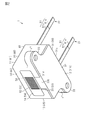
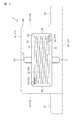
- the reactor 1 of the present embodiment is formed in a rectangular parallelepiped shape, and the upper surface 11 and the lower surface 12 facing the opposite sides and the side surfaces intersecting the upper surface 11 and the lower surface 12 and facing the opposite sides. It has side surfaces 15 and 16 that intersect 13 and 14, the upper surface 11 and the lower surface 12 and the side surfaces 13 and 14 and face opposite to each other.
- the term "rectangular parallelepiped” includes a rectangular parallelepiped in which the corners and ridges are chamfered and a rectangular parallelepiped in which the corners and ridges are rounded. Further, unevenness or the like may be formed on a part or all of the main surface and the side surface.
- the reactor 1 is arranged with the lower surface 12 facing the member to which the reactor 1 is attached, and is fixed to the member.
- the member to which the reactor 1 is attached is, for example, a heat radiating member such as a heat sink.
- the reactor 1 has two lead wires 21 and 22 extending from the side surface 13.
- the reactor 1 has a heat transfer member 30, a magnetic core 40, a non-magnetic layer 50, and a coil 60.
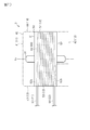
- the heat transfer member 30 has higher thermal conductivity than the magnetic core 40, such as aluminum (Al), copper (Cu), aluminum oxide (Al 2 O 3 ), aluminum nitride (AlN), and the like. Composed of good materials.
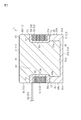
- the heat transfer member 30 has a base plate 31 and heat dissipation columns 34 and 35.
- the base plate 31 has a quadrangular plate-shaped base portion 32 and two fixing portions 33 extending from the base portion 32.
- the base plate 31 has an upper surface 31a and a lower surface 31b, a side surface 31c facing the extending direction of the lead wires 21 and 22, and a side surface 31d facing the side opposite to the side surface 31c. ing.
- the lower surface 31b of the base plate 31 constitutes the lower surface 12 of the reactor 1.
- the heat radiation columns 34 and 35 extend upward from the upper surface 31a of the base plate 31.
- the heat radiating columns 34 and 35 are formed in a rectangular parallelepiped shape.
- the heat radiating column 34 has an inner side surface 34a facing the side of the heat radiating column 35, an outer surface 34b facing the side opposite to the inner side surface 34a, and an upper surface 34c.
- the heat radiating column 35 has an inner side surface 35a facing the side of the heat radiating column 34, an outer surface 35b facing the side opposite to the inner side surface 35a, and an upper surface 35c.
- the heat radiation columns 34 and 35 are integrated with the base plate 31. Then, as shown in FIGS.
- the heat radiating column 34 is formed so that the outer surface 34b is flush with the side surface 31c of the base plate 31.
- the heat radiating column 35 is formed so that the outer surface 35b is flush with the side surface 31d of the base plate 31.
- the upper surfaces 34c and 35c of the heat radiation columns 34 and 35 are in close contact with the non-magnetic layer 50. That is, the tips of the heat radiating columns 34 and 35 extending upward from the base plate 31 are in contact with the non-magnetic layer 50.
- the non-magnetic layer 50 is formed so as to cover the coil 60.
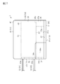
- the coil 60 is a spiral coil formed by winding one wire rod.
- the wire rod of the present embodiment is a flat wire.
- the flat wire is a wire rod having a rectangular cross-sectional shape orthogonal to the length direction of the wire rod.
- the "rectangle" includes a rectangle with chamfered corners and a rectangle with rounded corners.
- the "rectangular shape” includes a shape in which unevenness is formed on a part or all of the sides, and a shape in which a part or all of the sides are curved as a whole.
- a wire rod having a circular cross-sectional shape, an elliptical shape, or a square shape may be used as the wire rod constituting the coil.
- a foil-shaped conductor may be used as the wire rod. Further, conductors may be laminated to form a coil.
- the wire rod 61 constituting the coil 60 includes a core wire 61a and a coating material 61b that covers the surface of the core wire 61a.
- the core wire 61a is made of Cu, Al, an alloy containing Cu or Al as a main component.
- the coating material 61b is an insulating material, for example, an enamel material such as polyimide amide.
- the coil 60 of the present embodiment is formed by using a flat wire as a wire rod and winding the flat wire edgewise.
- the coil 60 may be formed by flatwise winding a flat wire.
- the coil 60 includes a winding portion 62 having a winding shaft Ax, and a first drawing portion 63 and a second drawing portion 64 extending from the first end 62a and the second end 62b of the winding portion 62, respectively.
- the first drawer portion 63 and the second drawer portion 64 form the lead wires 21 and 22 shown in FIG.
- the winding portion 62 is formed in a quadrangular frame shape when viewed from the direction of the winding shaft Ax.
- the corners of the winding portion 62 are formed in an arc shape (1/4 circle).
- the shape of the winding portion 62 may be a circular shape, an elliptical shape, a polygonal shape, or the like when viewed from the direction of the winding shaft Ax.
- the coil 60 is arranged so that the winding shaft Ax of the winding portion 62 is perpendicular to the lower surface 12 of the reactor 1.
- the non-magnetic layer 50 is formed so as to cover the winding portion 62.
- an insulating resin such as an epoxy resin or a silicone resin can be used.
- the surface of the non-magnetic layer 50 is flat.
- the non-magnetic layer 50 preferably covers, for example, the winding portion 62 with a thickness of 0.1 mm or more and 3 mm or less.
- the non-magnetic layer 50 preferably contains a filler such as silica powder or alumina powder, and preferably has a thermal conductivity of 1 W / m ⁇ K or more.
- the non-magnetic layer 50 can transfer heat satisfactorily.
- the non-magnetic layer 50 is formed by molding such as injection molding, transfer molding, sheet pressing, or the like.
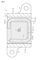
- the non-magnetic layer 50 is formed in a rectangular tubular shape.
- the non-magnetic layer 50 has an upper surface 51 and a lower surface 52, and side surfaces 53, 54, 55, 56.
- the side surfaces 53 and 54 of the non-magnetic layer 50 form the side surfaces 13 and 14 of the reactor 1.
- the non-magnetic layer 50 has an inner peripheral surface 58 forming a through hole 57 penetrating the non-magnetic layer 50 from the upper surface 51 to the lower surface 52.
- the winding portion 62 is exposed from the non-magnetic layer 50 on the side surface 54 of the non-magnetic layer 50. As shown in FIGS. 1 and 3, in the present embodiment, the winding portion 62 is covered with the non-magnetic layer 50 on the side surface 53 of the non-magnetic layer 50.
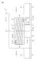
- the magnetic core 40 is formed so as to cover a part of the non-magnetic layer 50 and the heat transfer member 30.
- the magnetic core 40 is formed so as to cover the upper surface 31a of the base plate 31.
- the magnetic core 40 is formed so as to expose the outer surfaces 34b and 35b of the heat radiating columns 34 and 35. Further, the magnetic core 40 is formed so as to expose the side surfaces 53 and 54 of the non-magnetic layer 50. Therefore, as shown in FIG. 2, the winding portion 62 is exposed from the side surface 54 of the non-magnetic layer 50 and the side surface 44 of the magnetic core 40.
- At least one of the outer surfaces 34b and 35b of the heat radiating columns 34 and 35 may be covered with a member other than the magnetic core 40, for example, a resin such as an adhesive. Further, at least one of the side surfaces 53 and 54 of the non-magnetic layer 50 may be covered with a member other than the magnetic core 40, for example, a resin such as an adhesive.
- the magnetic core 40 has a rectangular parallelepiped outer shape.
- the magnetic core 40 has an upper surface 41, a lower surface 42, and side surfaces 43, 44, 45, 46.
- the upper surface 41 of the magnetic core 40 constitutes the upper surface 11 of the reactor 1.
- the lower surface 42 of the magnetic core 40 is in contact with the upper surface 31a of the base plate 31 of the heat transfer member 30.
- the side surfaces 43, 44, 45, 46 of the magnetic core 40 constitute the side surfaces 13, 14, 15, 16 of the reactor 1.
- the magnetic core 40 has a fixing portion 47 protruding from the side surfaces 45 and 46.
- the fixing portion 47 has the same shape as the fixing portion 33 of the base plate 31 when viewed from above.
- the magnetic core 40 is formed of a mixture of magnetic powder and resin.
- the magnetic powder include Fe-based amorphous powder, nanocrystal material, Fe, Fe-Si-Al-based, Fe-Si-based, Fe-Ni-based, Fe-Co-based soft magnetic metal material and ferrite material powder. , Etc. can be used.
- the resin an epoxy resin, a silicone resin, or the like can be used.
- the magnetic core 40 is formed by molding such as injection molding, transfer molding, sheet pressing, or the like.
- the magnetic core 40 is formed by arranging the structure created up to the non-magnetic layer 50 in the mold and filling the mold with the above-mentioned material.
- the reactor 1 has a winding portion 62 formed by winding a wire rod, and has a coil 60 arranged so that the winding portion 62 is parallel to the lower surface 12 and a non-covering portion 62. It has a magnetic layer 50, a magnetic core 40 that covers the non-magnetic layer 50, and a heat transfer member 30 that transfers heat inside toward the lower surface 12.
- heat is generated at the winding portion 62 of the coil 60 by energizing the coil 60.
- the heat inside the reactor 1 is transferred toward the lower surface 12 of the reactor 1 by the heat transfer member 30, and the heat is dissipated to the heat radiating member or the like to which the reactor 1 is attached. In this way, efficient heat dissipation from the coil 60 is possible.
- the heat transfer member 30 has a base plate 31 and heat radiating columns 34 and 35 extending from the upper surface 31a of the base plate 31.
- the upper surfaces 34c and 35c of the heat radiating columns 34 and 35 are in close contact with the non-magnetic layer 50 that covers the winding portion 62 of the coil 60. That is, the tips of the heat radiating columns 34 and 35 extending upward from the base plate 31 are in contact with the non-magnetic layer 50. Therefore, the heat generated in the winding portion 62 is transferred to the base plate 31 via the non-magnetic layer 50 and the heat radiating columns 34 and 35, and is radiated from the base plate 31 to the outside of the reactor 1. Therefore, efficient heat dissipation from the coil 60 is possible.
- the outer surfaces 34b and 35b of the heat radiation columns 34 and 35 are exposed from the magnetic core 40. Therefore, the heat transferred by the heat radiating columns 34 and 35 is radiated from the outer surfaces 34b and 35b of the heat radiating columns 34 and 35 to the outside of the reactor 1. Therefore, efficient heat dissipation from the coil 60 is possible.
- the upper surfaces 34c and 35c of the heat radiating columns 34 and 35 of the heat transfer member 30 are in close contact with the non-magnetic layer 50.
- the heat radiation columns 34 and 35 support the non-magnetic layer 50 at a predetermined distance from the base plate 31.
- the magnetic core 40 is interposed between the base plate 31 and the non-magnetic layer 50. A magnetic path is formed by the magnetic core 40.
- the reactor 1 has a winding portion 62 formed by winding a wire rod, and has a coil 60 arranged so that the winding portion 62 is parallel to the lower surface 12 and a winding portion. It has a non-magnetic layer 50 that covers 62, a magnetic core 40 that covers the non-magnetic layer 50, and a heat transfer member 30 that transfers heat inside toward the lower surface 12.
- heat is generated at the winding portion 62 of the coil 60 by energizing the coil 60.
- the heat inside the reactor 1 is transferred toward the lower surface 12 of the reactor 1 by the heat transfer member 30, and the heat is dissipated to the heat radiating member or the like to which the reactor 1 is attached. In this way, efficient heat dissipation from the coil 60 is possible.
- the heat transfer member 30 has a base plate 31 and heat radiating columns 34 and 35 extending from the upper surface 31a of the base plate 31.
- the upper surfaces 34c and 35c of the heat radiating columns 34 and 35 are in close contact with the non-magnetic layer 50 that covers the winding portion 62 of the coil 60. That is, the tips of the heat radiating columns 34 and 35 extending upward from the base plate 31 are in contact with the non-magnetic layer 50. Therefore, the heat generated in the winding portion 62 is transferred to the base plate 31 via the non-magnetic layer 50 and the heat radiating columns 34 and 35, and is radiated from the base plate 31 to the outside of the reactor 1. Therefore, efficient heat dissipation from the coil 60 is possible.
- the configuration of the heat transfer member 30 is different from that of the first embodiment.
- the heat transfer member 30 will be described, and the same reference numerals will be given to other constituent members, and some or all of the description will be omitted.
- the heat transfer member 30 has a base plate 31 and a heat radiating column 36.
- the heat transfer member 30 has one heat dissipation column 36.
- the heat radiating column 36 is arranged inside the winding portion 62 of the coil 60 formed in an annular shape. As shown in FIG. 15, the heat radiating column 36 extends upward from the upper surface 31a of the base plate 31.
- the heat radiation column 36 of this embodiment is integrated with the base plate 31.
- the heat radiating column 36 extends above the non-magnetic layer 50.
- the heat radiation column 36 of the present embodiment extends to the vicinity of the upper surface 41 of the magnetic core 40, that is, to the vicinity of the upper surface 11 of the reactor 2.
- the heat of the central portion and the upper portion of the reactor 2 is transferred to the base plate 31 by the heat radiating column 36 extending to the vicinity of the upper surface 11 of the reactor 2, and the reactor 2 is transferred from the base plate 31 to the base plate 31. Can dissipate heat to the outside of.
- the heat transfer member 30 has a base plate 31 and a heat radiation column 36 extending upward from the base plate 31 inside the winding portion 62 of the coil 60.
- the heat radiating column 36 extending to the vicinity of the upper surface 11 of the reactor 2 transfers the heat of the central portion and the upper portion of the reactor 2 to the base plate 31, and can dissipate heat from the base plate 31 to the outside of the reactor 2. Therefore, the heat radiating column 36 constitutes a heat radiating path in which heat is directed to the lower surface 12 of the reactor 2 inside the winding portion 62 of the coil 60. As a result, the heat of the coil 60 can be efficiently dissipated.
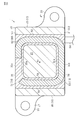
- the configurations of the non-magnetic layer 50 and the heat transfer member 37 are different from those of the first embodiment.
- the non-magnetic layer 50 and the heat transfer member 37 will be described, and the same reference numerals will be given to other constituent members, and some or all of the description will be omitted.
- the non-magnetic layer 50 of the present embodiment has a core dividing portion 59 that divides the magnetic core 40 inside the winding portion 62.
- the core dividing portion 59 forms a magnetic gap 77 in the magnetic core 40. That is, the magnetic core 40 has a magnetic gap 77.
- the magnetic gap 77 relaxes the magnetic saturation in the reactor 2 and improves the DC superimposition characteristic.
- the non-magnetic layer 50 is formed by, for example, injection molding, transfer molding, sheet pressing, or other molding. Therefore, there is little variation in the thickness of the core dividing portion 59. Therefore, the thickness of the core dividing portion 59, that is, the magnetic gap 77 can be set accurately in the magnetic core 40.
- the magnetic core 40 is formed by arranging the structure created up to the non-magnetic layer 50 in the mold and filling the mold with the above-mentioned material. Therefore, the magnetic gap 77 of the magnetic core 40 is easily formed by the core dividing portion 59 of the non-magnetic layer 50. Therefore, the reactor 3 can be easily formed without the need for the magnetic core 40 to be manufactured by dividing it or the steps of combining the divided cores.
- the non-magnetic layer 50 of the present embodiment covers the winding portion 62 on the side surface 54. That is, the winding portion 62 is not exposed.
- the winding portion 62 may be exposed on the side surface 54. Further, the winding portion 62 may be exposed on the side surface 53.
- the heat transfer member 37 of this embodiment is a heat pipe and does not have a base plate. That is, the lower surface 12 of the reactor 3 is the lower surface 42 of the magnetic core 40.
- the reactor 3 dissipates heat from the lower surface 42 of the magnetic core 40 to a member such as a heat radiating member to which the reactor 3 is attached.
- the heat pipe transfers heat by the phase change of the working fluid.
- the heat transfer member 37 includes a cylindrical main body 37a extending in the vertical direction of the reactor 3 and having an upper end and a lower end sealed therein, and a working fluid 37b (see FIG. 22) sealed inside the main body 37a. have.
- the main body 37a is made of a substance having good thermal conductivity, for example, a metal such as copper.
- As the working fluid 37b it is preferable to use a fluid having a high vapor pressure and a large latent heat of vaporization.
- As the working fluid 37b for example, ammonia, water, chlorofluorocarbon, alcohol, acetone, or the like can be used.
- the main body 37a moves the liquefied working fluid upward.
- the heat transfer member 37 is arranged so as to penetrate the core dividing portion 59.
- the heat transfer member 37 transfers heat from the upper part of the magnetic core 40 toward the lower surface 42 of the magnetic core 40.
- the non-magnetic layer 50 has a core dividing portion 59 that divides the magnetic core 40 inside the winding portion 62.
- the core dividing portion 59 forms a magnetic gap 77 in the magnetic core 40. That is, the magnetic core 40 has a magnetic gap 77.
- the magnetic gap 77 can alleviate the magnetic saturation in the reactor 2 and improve the DC superimposition characteristic.
- the heat transfer member 37 is a heat pipe.
- the heat transfer member 37 extends in the vertical direction of the reactor 3.
- the heat transfer member 37 can transfer the heat of the upper part of the magnetic core 40 toward the lower surface 12 of the reactor 3 (the lower surface 42 of the magnetic core 40).
- the magnetic core 40 of the reactor 4 shown in FIGS. 25 to 27 covers substantially the entire non-magnetic layer 50.
- the non-magnetic layer 50 has annular protective portions 53a and 53b protruding from the side surface 53 at a portion where the lead wires 21 and 22 extend, so that the magnetic core 40 does not come into contact with the lead wires 21 and 22. ..
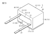
- the reactor 5 shown in FIG. 28 has a configuration in which the fixing portion 33 of the base plate 31 and the fixing portion 47 of the magnetic core 40 (see FIG. 1 and the like) are omitted.
- the reactor may be fixed by a separate member.
- the reactor 6 shown in FIGS. 29 and 30 is fixed to a member such as a heat radiating member by a fixing member 90.
- the base plate 31 has a fixing portion 33, and the fixing member 90 fixes the base plate 31 to a member such as a heat radiating member together with the fixing portion 33.
- the reactor having no fixed portion may be fixed to a member such as a heat radiating member by the fixing member 90.
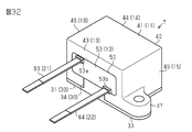
- the reactor 7 shown in FIGS. 31 and 32 includes annular protective portions 53a and 53b protruding from the side surface 53 in the non-magnetic layer 50 exposed from the side surface 43 of the magnetic core 40. .. In this reactor 7, the creepage distance from the magnetic core 40 to the lead wires 21 and 22 can be lengthened.
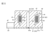
- the base plate 31 and the heat radiating column 36 may be separate bodies from the second embodiment.
- the heat radiating column 36 is fixed to the base plate 31 by a screw portion 36a formed at the lower end.
- a method of fixing the heat radiation column 36 a method such as welding can also be used.
- the material of the base plate 31 and the material of the heat radiating column 36 may be different from each other.
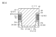
- the heat radiating columns 34 and 35 are embedded in the magnetic core 40, that is, the outer surfaces 34b and 35b of the heat radiating columns 34 and 35 are covered with the magnetic core 40. You may do so.
- the shape of the coil may be appropriately changed with respect to the above embodiment.
- a coil in which two winding portions 62 are connected in series may be used.
Abstract
The present disclosure provides a reactor that enables efficient heat dissipation from a coil. This reactor (1) comprises: a coil (60) which has a winding part (62) formed by winding a wire and which is disposed so as to have the winding part (62) situated parallel to an under surface (12); a non-magnetic layer (50) which covers the winding part (62); a magnetic core (40) which covers the non-magnetic layer (50); and a heat-transfer member (30) which transfers internal heat to the under surface (12).
Description
本開示は、リアクトルに関するものである。
This disclosure relates to reactors.
従来、リアクトルは、鉄心と、鉄心に絶縁物を介して巻回されたコイルとを備える。また、リアクトルは、コイルとの間に介在された熱伝導材シートを有している(例えば、特許文献1参照)。
Conventionally, the reactor is provided with an iron core and a coil wound around the iron core via an insulator. Further, the reactor has a heat conductive material sheet interposed between the reactor and the coil (see, for example, Patent Document 1).
ところで、上記のようなリアクトルは、熱伝導材シートによってコイルにて発生する熱を鉄心に放熱する。しかし、鉄心では、鉄心の損失による熱が生じるため、鉄心の温度が上昇し、コイルから放熱し難い。
By the way, the above reactor dissipates the heat generated by the coil by the heat conductive material sheet to the iron core. However, in the iron core, heat is generated due to the loss of the iron core, so that the temperature of the iron core rises and it is difficult to dissipate heat from the coil.
本開示の目的は、コイルから効率良い放熱を可能としたリアクトルを提供することにある。
The purpose of the present disclosure is to provide a reactor that enables efficient heat dissipation from the coil.
本開示の一態様であるリアクトルは、互いに反対側を向く上面及び下面を有し、前記下面を放熱部材の取付面に向けて取付けられるリアクトルであって、線材を巻回して形成された巻線部を有し、前記下面に対して前記巻線部を平行とするように配置されるコイルと、前記巻線部を被覆する非磁性層と、前記非磁性層を被覆する磁性体コアと、前記リアクトルの内部の熱を前記下面に向けて伝達する熱伝達部材と、を有する。
A reactor according to one aspect of the present disclosure is a reactor that has an upper surface and a lower surface facing opposite sides and is attached with the lower surface facing the mounting surface of a heat radiating member, and is a winding formed by winding a wire rod. A coil having a portion and arranged so that the winding portion is parallel to the lower surface, a non-magnetic layer covering the winding portion, and a magnetic core covering the non-magnetic layer. It has a heat transfer member that transfers heat inside the reactor toward the lower surface.
この構成によれば、リアクトルの内部では、コイルに対する通電により、コイルの巻線部にて発熱する。リアクトルは、熱伝達部材により、リアクトルの内部の熱がリアクトルの下面に向けて伝達され、リアクトルが取着された放熱部材等に放熱される。このように、コイルから効率良い放熱が可能となる。
According to this configuration, inside the reactor, heat is generated at the winding part of the coil due to the energization of the coil. In the reactor, the heat inside the reactor is transferred toward the lower surface of the reactor by the heat transfer member, and the heat is dissipated to the heat radiating member or the like to which the reactor is attached. In this way, efficient heat dissipation from the coil is possible.
本開示の一態様によれば、コイルから効率良い放熱を可能としたリアクトルを提供することができる。
According to one aspect of the present disclosure, it is possible to provide a reactor that enables efficient heat dissipation from the coil.
以下、各実施形態を説明する。
Hereinafter, each embodiment will be described.
なお、添付図面は、理解を容易にするために構成要素を拡大して示している場合がある。構成要素の寸法比率は実際のものと、または別の図面中のものと異なる場合がある。また、断面図では、理解を容易にするために、一部の構成要素のハッチングを省略している場合がある。
Note that the attached drawings may show enlarged components for easier understanding. The dimensional ratios of the components may differ from the actual ones or those in another drawing. Further, in the cross-sectional view, hatching of some components may be omitted for easy understanding.
(第1実施形態)
以下、第1実施形態のリアクトル1を図1から図8にしたがって説明する。 (First Embodiment)
Hereinafter, thereactor 1 of the first embodiment will be described with reference to FIGS. 1 to 8.
以下、第1実施形態のリアクトル1を図1から図8にしたがって説明する。 (First Embodiment)
Hereinafter, the
図1、図2に示すように、本実施形態のリアクトル1は、直方体状に形成され、互いに反対側を向く上面11及び下面12と、上面11及び下面12と交差し互いに反対側を向く側面13,14、上面11及び下面12及び側面13,14と交差し互いに反対側を向く側面15,16を有している。
As shown in FIGS. 1 and 2, the reactor 1 of the present embodiment is formed in a rectangular parallelepiped shape, and the upper surface 11 and the lower surface 12 facing the opposite sides and the side surfaces intersecting the upper surface 11 and the lower surface 12 and facing the opposite sides. It has side surfaces 15 and 16 that intersect 13 and 14, the upper surface 11 and the lower surface 12 and the side surfaces 13 and 14 and face opposite to each other.
なお、本明細書において、「直方体状」には、角部や稜線部が面取りされた直方体や、角部や稜線部が丸められた直方体が含まれるものとする。また、主面及び側面の一部又は全部に凹凸などが形成されていてもよい。
In the present specification, the term "rectangular parallelepiped" includes a rectangular parallelepiped in which the corners and ridges are chamfered and a rectangular parallelepiped in which the corners and ridges are rounded. Further, unevenness or the like may be formed on a part or all of the main surface and the side surface.
リアクトル1は、下面12をこのリアクトル1を取付ける部材に向けて配置され、その部材に固定される。リアクトル1を取付ける部材は、例えばヒートシンク等の放熱部材である。リアクトル1は、側面13から延出する2本のリード線21,22を有している。
The reactor 1 is arranged with the lower surface 12 facing the member to which the reactor 1 is attached, and is fixed to the member. The member to which the reactor 1 is attached is, for example, a heat radiating member such as a heat sink. The reactor 1 has two lead wires 21 and 22 extending from the side surface 13.
図1から図8に示すように、リアクトル1は、熱伝達部材30、磁性体コア40、非磁性層50、コイル60を有している。
As shown in FIGS. 1 to 8, the reactor 1 has a heat transfer member 30, a magnetic core 40, a non-magnetic layer 50, and a coil 60.
熱伝達部材30は、磁性体コア40よりも熱伝導率の高い材料、例えばアルミニウム(Al)、銅(Cu)、酸化アルミニウム(Al2O3)、窒化アルミニウム(AlN)、等の熱伝導性のよい材料から構成される。
The heat transfer member 30 has higher thermal conductivity than the magnetic core 40, such as aluminum (Al), copper (Cu), aluminum oxide (Al 2 O 3 ), aluminum nitride (AlN), and the like. Composed of good materials.
熱伝達部材30は、ベース板31と、放熱柱34,35とを有している。
The heat transfer member 30 has a base plate 31 and heat dissipation columns 34 and 35.
ベース板31は、四角形板状のベース部32と、ベース部32から延びる2つ固定部33とを有している。
The base plate 31 has a quadrangular plate-shaped base portion 32 and two fixing portions 33 extending from the base portion 32.
図3、図4に示すように、ベース板31は、上面31a及び下面31bと、リード線21,22の延出方向を向く側面31cと、側面31cと反対側を向く側面31dとを有している。ベース板31の下面31bは、リアクトル1の下面12を構成する。
As shown in FIGS. 3 and 4, the base plate 31 has an upper surface 31a and a lower surface 31b, a side surface 31c facing the extending direction of the lead wires 21 and 22, and a side surface 31d facing the side opposite to the side surface 31c. ing. The lower surface 31b of the base plate 31 constitutes the lower surface 12 of the reactor 1.
放熱柱34,35は、ベース板31の上面31aから上方へ延びている。本実施形態において、各放熱柱34,35は、直方体状に形成されている。図4に示すように、放熱柱34は、放熱柱35の側を向く内側面34aと、この内側面34aと反対側を向く外側面34bと、上面34cとを有している。同様に、放熱柱35は、放熱柱34の側を向く内側面35aと、この内側面35aと反対側を向く外側面35bと、上面35cとを有している。本実施形態において、各放熱柱34,35は、ベース板31と一体である。そして、図1、図4に示すように、放熱柱34は、外側面34bをベース板31の側面31cと面一とするように形成されている。図2、図4に示すように、放熱柱35は、外側面35bをベース板31の側面31dと面一とするように形成されている。
The heat radiation columns 34 and 35 extend upward from the upper surface 31a of the base plate 31. In the present embodiment, the heat radiating columns 34 and 35 are formed in a rectangular parallelepiped shape. As shown in FIG. 4, the heat radiating column 34 has an inner side surface 34a facing the side of the heat radiating column 35, an outer surface 34b facing the side opposite to the inner side surface 34a, and an upper surface 34c. Similarly, the heat radiating column 35 has an inner side surface 35a facing the side of the heat radiating column 34, an outer surface 35b facing the side opposite to the inner side surface 35a, and an upper surface 35c. In the present embodiment, the heat radiation columns 34 and 35 are integrated with the base plate 31. Then, as shown in FIGS. 1 and 4, the heat radiating column 34 is formed so that the outer surface 34b is flush with the side surface 31c of the base plate 31. As shown in FIGS. 2 and 4, the heat radiating column 35 is formed so that the outer surface 35b is flush with the side surface 31d of the base plate 31.
図4、図7に示すように、放熱柱34,35の上面34c,35cは、非磁性層50に密着している。つまり、ベース板31から上方に延びる放熱柱34,35の先端は、非磁性層50に接している。非磁性層50は、コイル60を覆うように形成されている。
As shown in FIGS. 4 and 7, the upper surfaces 34c and 35c of the heat radiation columns 34 and 35 are in close contact with the non-magnetic layer 50. That is, the tips of the heat radiating columns 34 and 35 extending upward from the base plate 31 are in contact with the non-magnetic layer 50. The non-magnetic layer 50 is formed so as to cover the coil 60.
ここで、コイル60について説明する。コイル60は、1本の線材を巻き回してなる螺旋状のコイルである。本実施形態の線材は、平角線である。平角線は、線材の長さ方向に直交する断面形状が長方形状の線材である。なお、本明細書において、「長方形状」には、角部が面取りされた長方形や、角部が丸められた長方形が含まれるものとする。また、「長方形状」には、辺の一部又は全部に凹凸が形成されているもの、一部又は全部の辺が全体的に湾曲しているものが含まれるものとする。なお、コイルを構成する線材として、断面形状が円形状や楕円形状や正方形状の線材が用いられてもよい。線材として、箔体状の導体が用いられてもよい。また、導体を積層してコイルを構成してもよい。
Here, the coil 60 will be described. The coil 60 is a spiral coil formed by winding one wire rod. The wire rod of the present embodiment is a flat wire. The flat wire is a wire rod having a rectangular cross-sectional shape orthogonal to the length direction of the wire rod. In the present specification, the "rectangle" includes a rectangle with chamfered corners and a rectangle with rounded corners. Further, the "rectangular shape" includes a shape in which unevenness is formed on a part or all of the sides, and a shape in which a part or all of the sides are curved as a whole. As the wire rod constituting the coil, a wire rod having a circular cross-sectional shape, an elliptical shape, or a square shape may be used. A foil-shaped conductor may be used as the wire rod. Further, conductors may be laminated to form a coil.
コイル60を構成する線材61は、芯線61aと、芯線61aの表面を被覆する被覆材61bとを含む。芯線61aは、Cu、Al、CuやAlを主成分とする合金からなる。被覆材61bは、絶縁材料、例えばポリイミドアミド等のエナメル材である。本実施形態のコイル60は、線材として平角線を用い、その平角線をエッジワイズ巻きして形成されている。なお、平角線をフラットワイズ巻きしてコイル60が形成されてもよい。
The wire rod 61 constituting the coil 60 includes a core wire 61a and a coating material 61b that covers the surface of the core wire 61a. The core wire 61a is made of Cu, Al, an alloy containing Cu or Al as a main component. The coating material 61b is an insulating material, for example, an enamel material such as polyimide amide. The coil 60 of the present embodiment is formed by using a flat wire as a wire rod and winding the flat wire edgewise. The coil 60 may be formed by flatwise winding a flat wire.
コイル60は、巻軸Axを有する巻線部62と、巻線部62の第1端62aと第2端62bとからそれぞれ延びる第1引出部63と第2引出部64を備えている。第1引出部63と第2引出部64は、図1に示すリード線21,22を構成する。図5に示すように、巻線部62は、巻軸Axの方向から視て、四角形の枠状に形成されている。巻線部62の角部は、円弧状(1/4円)に形成されている。なお、巻線部62の形状は、巻軸Axの方向から視て、円形状、楕円形状や多角形状等の形状としてもよい。コイル60は、巻線部62の巻軸Axをリアクトル1の下面12に対して垂直とするように配置されている。
The coil 60 includes a winding portion 62 having a winding shaft Ax, and a first drawing portion 63 and a second drawing portion 64 extending from the first end 62a and the second end 62b of the winding portion 62, respectively. The first drawer portion 63 and the second drawer portion 64 form the lead wires 21 and 22 shown in FIG. As shown in FIG. 5, the winding portion 62 is formed in a quadrangular frame shape when viewed from the direction of the winding shaft Ax. The corners of the winding portion 62 are formed in an arc shape (1/4 circle). The shape of the winding portion 62 may be a circular shape, an elliptical shape, a polygonal shape, or the like when viewed from the direction of the winding shaft Ax. The coil 60 is arranged so that the winding shaft Ax of the winding portion 62 is perpendicular to the lower surface 12 of the reactor 1.
非磁性層50に戻って説明する。
Returning to the non-magnetic layer 50, the explanation will be given.
非磁性層50は、巻線部62を覆うように形成されている。非磁性層50の材料は、エポキシ樹脂、シリコーン樹脂、等の絶縁樹脂を用いることができる。非磁性層50の表面は平坦である。非磁性層50は、例えば巻線部62を、0.1mm以上3mm以下の厚さで覆うことが好ましい。また、非磁性層50は、シリカ粉やアルミナ粉等のフィラーを含むことが好ましく、また熱伝導率が1W/m・K以上であることが好ましい。この非磁性層50により、良好に熱を伝達できる。非磁性層50は、例えば射出成形、トランスファー成形、シートプレス、等のモールド成形により形成される。
The non-magnetic layer 50 is formed so as to cover the winding portion 62. As the material of the non-magnetic layer 50, an insulating resin such as an epoxy resin or a silicone resin can be used. The surface of the non-magnetic layer 50 is flat. The non-magnetic layer 50 preferably covers, for example, the winding portion 62 with a thickness of 0.1 mm or more and 3 mm or less. Further, the non-magnetic layer 50 preferably contains a filler such as silica powder or alumina powder, and preferably has a thermal conductivity of 1 W / m · K or more. The non-magnetic layer 50 can transfer heat satisfactorily. The non-magnetic layer 50 is formed by molding such as injection molding, transfer molding, sheet pressing, or the like.
図3及び図4に示すように、非磁性層50は、四角形の筒状に形成されている。非磁性層50は、上面51及び下面52、側面53,54,55,56を有している。非磁性層50の側面53,54は、リアクトル1の側面13,14を構成する。そして、非磁性層50は、上面51から下面52まで非磁性層50を貫通する貫通孔57を構成する内周面58を有している。
As shown in FIGS. 3 and 4, the non-magnetic layer 50 is formed in a rectangular tubular shape. The non-magnetic layer 50 has an upper surface 51 and a lower surface 52, and side surfaces 53, 54, 55, 56. The side surfaces 53 and 54 of the non-magnetic layer 50 form the side surfaces 13 and 14 of the reactor 1. The non-magnetic layer 50 has an inner peripheral surface 58 forming a through hole 57 penetrating the non-magnetic layer 50 from the upper surface 51 to the lower surface 52.
図2に示すように、巻線部62は、非磁性層50の側面54において非磁性層50から露出している。図1、図3に示すように、本実施形態において、巻線部62は、非磁性層50の側面53において、非磁性層50により覆われている。
As shown in FIG. 2, the winding portion 62 is exposed from the non-magnetic layer 50 on the side surface 54 of the non-magnetic layer 50. As shown in FIGS. 1 and 3, in the present embodiment, the winding portion 62 is covered with the non-magnetic layer 50 on the side surface 53 of the non-magnetic layer 50.
磁性体コア40は、非磁性層50と熱伝達部材30の一部を覆うように形成されている。
The magnetic core 40 is formed so as to cover a part of the non-magnetic layer 50 and the heat transfer member 30.
図1、図2に示すように、磁性体コア40は、ベース板31の上面31aを覆うように形成されている。そして、磁性体コア40は、放熱柱34,35の外側面34b,35bを露出するように形成されている。また、磁性体コア40は、非磁性層50の側面53,54を露出するように形成されている。したがって、図2に示すように、巻線部62は、非磁性層50の側面54、及び磁性体コア40の側面44から露出している。
As shown in FIGS. 1 and 2, the magnetic core 40 is formed so as to cover the upper surface 31a of the base plate 31. The magnetic core 40 is formed so as to expose the outer surfaces 34b and 35b of the heat radiating columns 34 and 35. Further, the magnetic core 40 is formed so as to expose the side surfaces 53 and 54 of the non-magnetic layer 50. Therefore, as shown in FIG. 2, the winding portion 62 is exposed from the side surface 54 of the non-magnetic layer 50 and the side surface 44 of the magnetic core 40.
なお、放熱柱34,35の外側面34b,35bの少なくとも一方は、磁性体コア40以外の部材、例えば接着剤等の樹脂により覆われていてもよい。また、非磁性層50の側面53,54の少なくとも一方は、磁性体コア40以外の部材、例えば接着剤等の樹脂により覆われていてもよい。
At least one of the outer surfaces 34b and 35b of the heat radiating columns 34 and 35 may be covered with a member other than the magnetic core 40, for example, a resin such as an adhesive. Further, at least one of the side surfaces 53 and 54 of the non-magnetic layer 50 may be covered with a member other than the magnetic core 40, for example, a resin such as an adhesive.
磁性体コア40は、直方体状の外形を有している。磁性体コア40は、上面41、下面42、側面43,44,45,46を有している。磁性体コア40の上面41は、リアクトル1の上面11を構成する。磁性体コア40の下面42は、熱伝達部材30のベース板31の上面31aに接している。磁性体コア40の側面43,44,45,46は、リアクトル1の側面13,14,15,16を構成する。磁性体コア40は、側面45,46から突出する固定部47を有している。固定部47は、上方から視て、ベース板31の固定部33と同じ形状である。
The magnetic core 40 has a rectangular parallelepiped outer shape. The magnetic core 40 has an upper surface 41, a lower surface 42, and side surfaces 43, 44, 45, 46. The upper surface 41 of the magnetic core 40 constitutes the upper surface 11 of the reactor 1. The lower surface 42 of the magnetic core 40 is in contact with the upper surface 31a of the base plate 31 of the heat transfer member 30. The side surfaces 43, 44, 45, 46 of the magnetic core 40 constitute the side surfaces 13, 14, 15, 16 of the reactor 1. The magnetic core 40 has a fixing portion 47 protruding from the side surfaces 45 and 46. The fixing portion 47 has the same shape as the fixing portion 33 of the base plate 31 when viewed from above.
磁性体コア40は、磁性粉末と樹脂との混合物により形成される。磁性粉末としては、例えばFe系アモルファス粉末、ナノ結晶材料、Fe、Fe-Si-Al系、Fe-Si系、Fe-Ni系、Fe-Co系などからなる軟磁性金属材料やフェライト材料の粉末、等を用いることができる。樹脂としては、エポキシ樹脂、シリコーン樹脂、等を用いることができる。磁性体コア40は、例えば射出成形、トランスファー成形、シートプレス、等のモールド成形により形成される。磁性体コア40は、非磁性層50まで作成した構造体をモールド金型内に配置し、モールド金型内に充填した上記の材料により形成される。
The magnetic core 40 is formed of a mixture of magnetic powder and resin. Examples of the magnetic powder include Fe-based amorphous powder, nanocrystal material, Fe, Fe-Si-Al-based, Fe-Si-based, Fe-Ni-based, Fe-Co-based soft magnetic metal material and ferrite material powder. , Etc. can be used. As the resin, an epoxy resin, a silicone resin, or the like can be used. The magnetic core 40 is formed by molding such as injection molding, transfer molding, sheet pressing, or the like. The magnetic core 40 is formed by arranging the structure created up to the non-magnetic layer 50 in the mold and filling the mold with the above-mentioned material.
(作用)
リアクトル1は、線材を巻回して形成された巻線部62を有し、下面12に対して巻線部62を平行とするように配置されるコイル60と、巻線部62を被覆する非磁性層50と、非磁性層50を被覆する磁性体コア40と、内部の熱を下面12に向けて伝達する熱伝達部材30と、を有している。リアクトル1の内部では、コイル60に対する通電により、コイル60の巻線部62にて発熱する。リアクトル1は、熱伝達部材30により、リアクトル1の内部の熱がリアクトル1の下面12に向けて伝達され、リアクトル1が取着された放熱部材等に放熱される。このように、コイル60から効率良い放熱が可能となる。 (Action)
Thereactor 1 has a winding portion 62 formed by winding a wire rod, and has a coil 60 arranged so that the winding portion 62 is parallel to the lower surface 12 and a non-covering portion 62. It has a magnetic layer 50, a magnetic core 40 that covers the non-magnetic layer 50, and a heat transfer member 30 that transfers heat inside toward the lower surface 12. Inside the reactor 1, heat is generated at the winding portion 62 of the coil 60 by energizing the coil 60. In the reactor 1, the heat inside the reactor 1 is transferred toward the lower surface 12 of the reactor 1 by the heat transfer member 30, and the heat is dissipated to the heat radiating member or the like to which the reactor 1 is attached. In this way, efficient heat dissipation from the coil 60 is possible.
リアクトル1は、線材を巻回して形成された巻線部62を有し、下面12に対して巻線部62を平行とするように配置されるコイル60と、巻線部62を被覆する非磁性層50と、非磁性層50を被覆する磁性体コア40と、内部の熱を下面12に向けて伝達する熱伝達部材30と、を有している。リアクトル1の内部では、コイル60に対する通電により、コイル60の巻線部62にて発熱する。リアクトル1は、熱伝達部材30により、リアクトル1の内部の熱がリアクトル1の下面12に向けて伝達され、リアクトル1が取着された放熱部材等に放熱される。このように、コイル60から効率良い放熱が可能となる。 (Action)
The
熱伝達部材30は、ベース板31と、ベース板31の上面31aから延びる放熱柱34,35とを有している。放熱柱34,35の上面34c,35cは、コイル60の巻線部62を覆う非磁性層50に密着している。つまり、ベース板31から上方に延びる放熱柱34,35の先端は、非磁性層50に接している。したがって、巻線部62にて発生する熱は、非磁性層50と放熱柱34,35とを介してベース板31に伝達され、そのベース板31からリアクトル1の外部へと放熱される。従って、コイル60から効率良い放熱が可能となる。
The heat transfer member 30 has a base plate 31 and heat radiating columns 34 and 35 extending from the upper surface 31a of the base plate 31. The upper surfaces 34c and 35c of the heat radiating columns 34 and 35 are in close contact with the non-magnetic layer 50 that covers the winding portion 62 of the coil 60. That is, the tips of the heat radiating columns 34 and 35 extending upward from the base plate 31 are in contact with the non-magnetic layer 50. Therefore, the heat generated in the winding portion 62 is transferred to the base plate 31 via the non-magnetic layer 50 and the heat radiating columns 34 and 35, and is radiated from the base plate 31 to the outside of the reactor 1. Therefore, efficient heat dissipation from the coil 60 is possible.
放熱柱34,35の外側面34b,35bは、磁性体コア40から露出している。したがって、放熱柱34,35が伝達する熱は、放熱柱34,35の外側面34b,35bからリアクトル1の外部へと放熱される。従って、コイル60から効率良い放熱が可能となる。
The outer surfaces 34b and 35b of the heat radiation columns 34 and 35 are exposed from the magnetic core 40. Therefore, the heat transferred by the heat radiating columns 34 and 35 is radiated from the outer surfaces 34b and 35b of the heat radiating columns 34 and 35 to the outside of the reactor 1. Therefore, efficient heat dissipation from the coil 60 is possible.
図4、図7に示すように、熱伝達部材30の放熱柱34,35の上面34c,35cは、非磁性層50に密着している。そして、放熱柱34,35は、ベース板31から所定の距離にて非磁性層50を支持している。これにより、図6に示すように、ベース板31と非磁性層50との間に磁性体コア40が介在する。この磁性体コア40により、磁路が形成される。
As shown in FIGS. 4 and 7, the upper surfaces 34c and 35c of the heat radiating columns 34 and 35 of the heat transfer member 30 are in close contact with the non-magnetic layer 50. The heat radiation columns 34 and 35 support the non-magnetic layer 50 at a predetermined distance from the base plate 31. As a result, as shown in FIG. 6, the magnetic core 40 is interposed between the base plate 31 and the non-magnetic layer 50. A magnetic path is formed by the magnetic core 40.
以上記述したように、本実施形態によれば、以下の効果を奏する。
As described above, according to this embodiment, the following effects are obtained.
(1-1)リアクトル1は、線材を巻回して形成された巻線部62を有し、下面12に対して巻線部62を平行とするように配置されるコイル60と、巻線部62を被覆する非磁性層50と、非磁性層50を被覆する磁性体コア40と、内部の熱を下面12に向けて伝達する熱伝達部材30と、を有している。リアクトル1の内部では、コイル60に対する通電により、コイル60の巻線部62にて発熱する。リアクトル1は、熱伝達部材30により、リアクトル1の内部の熱がリアクトル1の下面12に向けて伝達され、リアクトル1が取着された放熱部材等に放熱される。このように、コイル60から効率良い放熱が可能となる。
(1-1) The reactor 1 has a winding portion 62 formed by winding a wire rod, and has a coil 60 arranged so that the winding portion 62 is parallel to the lower surface 12 and a winding portion. It has a non-magnetic layer 50 that covers 62, a magnetic core 40 that covers the non-magnetic layer 50, and a heat transfer member 30 that transfers heat inside toward the lower surface 12. Inside the reactor 1, heat is generated at the winding portion 62 of the coil 60 by energizing the coil 60. In the reactor 1, the heat inside the reactor 1 is transferred toward the lower surface 12 of the reactor 1 by the heat transfer member 30, and the heat is dissipated to the heat radiating member or the like to which the reactor 1 is attached. In this way, efficient heat dissipation from the coil 60 is possible.
(1-2)熱伝達部材30は、ベース板31と、ベース板31の上面31aから延びる放熱柱34,35とを有している。放熱柱34,35の上面34c,35cは、コイル60の巻線部62を覆う非磁性層50に密着している。つまり、ベース板31から上方に延びる放熱柱34,35の先端は、非磁性層50に接している。したがって、巻線部62にて発生する熱は、非磁性層50と放熱柱34,35とを介してベース板31に伝達され、そのベース板31からリアクトル1の外部へと放熱される。従って、コイル60から効率良い放熱が可能となる。
(1-2) The heat transfer member 30 has a base plate 31 and heat radiating columns 34 and 35 extending from the upper surface 31a of the base plate 31. The upper surfaces 34c and 35c of the heat radiating columns 34 and 35 are in close contact with the non-magnetic layer 50 that covers the winding portion 62 of the coil 60. That is, the tips of the heat radiating columns 34 and 35 extending upward from the base plate 31 are in contact with the non-magnetic layer 50. Therefore, the heat generated in the winding portion 62 is transferred to the base plate 31 via the non-magnetic layer 50 and the heat radiating columns 34 and 35, and is radiated from the base plate 31 to the outside of the reactor 1. Therefore, efficient heat dissipation from the coil 60 is possible.
(1-3)放熱柱34,35の外側面34b,35bは、磁性体コア40から露出している。したがって、放熱柱34,35が伝達する熱は、放熱柱34,35の外側面34b,35bからリアクトル1の外部へと放熱される。従って、コイル60から効率良い放熱が可能となる。
(1-3) The outer surfaces 34b and 35b of the heat radiation columns 34 and 35 are exposed from the magnetic core 40. Therefore, the heat transferred by the heat radiating columns 34 and 35 is radiated from the outer surfaces 34b and 35b of the heat radiating columns 34 and 35 to the outside of the reactor 1. Therefore, efficient heat dissipation from the coil 60 is possible.
(第2実施形態)
以下、第2実施形態のリアクトル2を図9から図16にしたがって説明する。 (Second Embodiment)
Hereinafter, thereactor 2 of the second embodiment will be described with reference to FIGS. 9 to 16.
以下、第2実施形態のリアクトル2を図9から図16にしたがって説明する。 (Second Embodiment)
Hereinafter, the
なお、第2実施形態のリアクトル2において、熱伝達部材30の構成が第1実施形態と異なる。本実施形態では、熱伝達部材30について説明し、他の構成部材については同じ符号を付して説明の一部または全てを省略する。
In the reactor 2 of the second embodiment, the configuration of the heat transfer member 30 is different from that of the first embodiment. In the present embodiment, the heat transfer member 30 will be described, and the same reference numerals will be given to other constituent members, and some or all of the description will be omitted.
図11から図16に示すように、熱伝達部材30は、ベース板31と、放熱柱36とを有している。本実施形態において、熱伝達部材30は、1つの放熱柱36を有している。放熱柱36は、環状に形成されたコイル60の巻線部62の内側に配設されている。図15に示すように、放熱柱36は、ベース板31の上面31aから上方に延びている。本実施形態の放熱柱36は、ベース板31と一体である。そして、放熱柱36は、非磁性層50よりも上方に延びている。本実施形態の放熱柱36は、磁性体コア40の上面41の付近、つまりリアクトル2の上面11の付近まで延びている。
As shown in FIGS. 11 to 16, the heat transfer member 30 has a base plate 31 and a heat radiating column 36. In the present embodiment, the heat transfer member 30 has one heat dissipation column 36. The heat radiating column 36 is arranged inside the winding portion 62 of the coil 60 formed in an annular shape. As shown in FIG. 15, the heat radiating column 36 extends upward from the upper surface 31a of the base plate 31. The heat radiation column 36 of this embodiment is integrated with the base plate 31. The heat radiating column 36 extends above the non-magnetic layer 50. The heat radiation column 36 of the present embodiment extends to the vicinity of the upper surface 41 of the magnetic core 40, that is, to the vicinity of the upper surface 11 of the reactor 2.
本実施形態の熱伝達部材30では、リアクトル2の上面11の付近まで延びている放熱柱36により、リアクトル2の中央部分及び上部の熱をベース板31に伝達し、そのベース板31からリアクトル2の外部へと放熱できる。
In the heat transfer member 30 of the present embodiment, the heat of the central portion and the upper portion of the reactor 2 is transferred to the base plate 31 by the heat radiating column 36 extending to the vicinity of the upper surface 11 of the reactor 2, and the reactor 2 is transferred from the base plate 31 to the base plate 31. Can dissipate heat to the outside of.
以上記述したように、本実施形態によれば、以下の効果を奏する。
As described above, according to this embodiment, the following effects are obtained.
(2-1)熱伝達部材30は、ベース板31と、コイル60の巻線部62の内側において、ベース板31から上方へ延びる放熱柱36とを有している。リアクトル2の上面11の付近まで延びている放熱柱36により、リアクトル2の中央部分及び上部の熱をベース板31に伝達し、そのベース板31からリアクトル2の外部へと放熱できる。従って、放熱柱36は、コイル60の巻線部62の内側において熱をリアクトル2の下面12に向かう放熱経路を構成する。これにより、コイル60の熱を効率よく放熱できる。
(2-1) The heat transfer member 30 has a base plate 31 and a heat radiation column 36 extending upward from the base plate 31 inside the winding portion 62 of the coil 60. The heat radiating column 36 extending to the vicinity of the upper surface 11 of the reactor 2 transfers the heat of the central portion and the upper portion of the reactor 2 to the base plate 31, and can dissipate heat from the base plate 31 to the outside of the reactor 2. Therefore, the heat radiating column 36 constitutes a heat radiating path in which heat is directed to the lower surface 12 of the reactor 2 inside the winding portion 62 of the coil 60. As a result, the heat of the coil 60 can be efficiently dissipated.
(第3実施形態)
以下、第3実施形態のリアクトル3を図17から図24にしたがって説明する。 (Third Embodiment)
Hereinafter, thereactor 3 of the third embodiment will be described with reference to FIGS. 17 to 24.
以下、第3実施形態のリアクトル3を図17から図24にしたがって説明する。 (Third Embodiment)
Hereinafter, the
なお、第3実施形態のリアクトル3において、非磁性層50と熱伝達部材37の構成が第1実施形態と異なる。本実施形態では、非磁性層50と熱伝達部材37について説明し、他の構成部材については同じ符号を付して説明の一部または全てを省略する。
In the reactor 3 of the third embodiment, the configurations of the non-magnetic layer 50 and the heat transfer member 37 are different from those of the first embodiment. In the present embodiment, the non-magnetic layer 50 and the heat transfer member 37 will be described, and the same reference numerals will be given to other constituent members, and some or all of the description will be omitted.
図19から図24に示すように、本実施形態の非磁性層50は、巻線部62の内側において、磁性体コア40を分割するコア分割部59を有している。このコア分割部59は、磁性体コア40に磁気ギャップ77を形成する。つまり、磁性体コア40は磁気ギャップ77を有している。磁気ギャップ77は、リアクトル2における磁気飽和を緩和し、直流重畳特性を改善する。
As shown in FIGS. 19 to 24, the non-magnetic layer 50 of the present embodiment has a core dividing portion 59 that divides the magnetic core 40 inside the winding portion 62. The core dividing portion 59 forms a magnetic gap 77 in the magnetic core 40. That is, the magnetic core 40 has a magnetic gap 77. The magnetic gap 77 relaxes the magnetic saturation in the reactor 2 and improves the DC superimposition characteristic.
非磁性層50は、例えば射出成形、トランスファー成形、シートプレス、等のモールド成形により形成される。従って、コア分割部59の厚さにばらつきが少ない。このため、コア分割部59の厚さ、つまり磁性体コア40において、磁気ギャップ77を精度よく設定できる。磁性体コア40は、非磁性層50まで作成した構造体をモールド金型内に配置し、モールド金型内に充填した上記の材料により形成される。したがって、磁性体コア40の磁気ギャップ77は、非磁性層50のコア分割部59によって容易に形成される。このため、磁性体コア40を分割して製造することや、分割したコアを合わせる工程等を必要とせず、リアクトル3を容易に形成できる。
The non-magnetic layer 50 is formed by, for example, injection molding, transfer molding, sheet pressing, or other molding. Therefore, there is little variation in the thickness of the core dividing portion 59. Therefore, the thickness of the core dividing portion 59, that is, the magnetic gap 77 can be set accurately in the magnetic core 40. The magnetic core 40 is formed by arranging the structure created up to the non-magnetic layer 50 in the mold and filling the mold with the above-mentioned material. Therefore, the magnetic gap 77 of the magnetic core 40 is easily formed by the core dividing portion 59 of the non-magnetic layer 50. Therefore, the reactor 3 can be easily formed without the need for the magnetic core 40 to be manufactured by dividing it or the steps of combining the divided cores.
図20に示すように、本実施形態の非磁性層50は、側面54において、巻線部62を覆っている。つまり、巻線部62は露出されていない。なお、側面54において、巻線部62を露出するようにしてもよい。また、側面53において、巻線部62を露出するようにしてもよい。
As shown in FIG. 20, the non-magnetic layer 50 of the present embodiment covers the winding portion 62 on the side surface 54. That is, the winding portion 62 is not exposed. The winding portion 62 may be exposed on the side surface 54. Further, the winding portion 62 may be exposed on the side surface 53.
本実施形態の熱伝達部材37は、ヒートパイプであり、ベース板を備えていない。つまり、リアクトル3の下面12は、磁性体コア40の下面42である。リアクトル3は、磁性体コア40の下面42から、リアクトル3が取付けられる放熱部材等の部材へ放熱する。
The heat transfer member 37 of this embodiment is a heat pipe and does not have a base plate. That is, the lower surface 12 of the reactor 3 is the lower surface 42 of the magnetic core 40. The reactor 3 dissipates heat from the lower surface 42 of the magnetic core 40 to a member such as a heat radiating member to which the reactor 3 is attached.
ヒートパイプは、作動流体の相変化により熱を伝達する。熱伝達部材37は、リアクトル3の上下方向に延び、上端と下端とがそれぞれ封止された筒状の本体部37aと、本体部37aの内部に封入された作動流体37b(図22参照)とを有している。本体部37aは、熱伝導性のよい物質、例えば銅等の金属により構成される。作動流体37bは、蒸気圧が高く、蒸発潜熱が大きい流体を使用するのが好ましい。作動流体37bとしては、例えば、アンモニア、水、フロン、アルコール、アセトン、等を用いることができる。本体部37aは、液化した作動流体を上方へと移動させる。
The heat pipe transfers heat by the phase change of the working fluid. The heat transfer member 37 includes a cylindrical main body 37a extending in the vertical direction of the reactor 3 and having an upper end and a lower end sealed therein, and a working fluid 37b (see FIG. 22) sealed inside the main body 37a. have. The main body 37a is made of a substance having good thermal conductivity, for example, a metal such as copper. As the working fluid 37b, it is preferable to use a fluid having a high vapor pressure and a large latent heat of vaporization. As the working fluid 37b, for example, ammonia, water, chlorofluorocarbon, alcohol, acetone, or the like can be used. The main body 37a moves the liquefied working fluid upward.
本実施形態において、熱伝達部材37は、コア分割部59を貫通して配置されている。この熱伝達部材37は、磁性体コア40の上部の熱を、磁性体コア40の下面42に向けて伝達する。
In the present embodiment, the heat transfer member 37 is arranged so as to penetrate the core dividing portion 59. The heat transfer member 37 transfers heat from the upper part of the magnetic core 40 toward the lower surface 42 of the magnetic core 40.
以上記述したように、本実施形態によれば、以下の効果を奏する。
As described above, according to this embodiment, the following effects are obtained.
(3-1)非磁性層50は、巻線部62の内側において、磁性体コア40を分割するコア分割部59を有している。このコア分割部59は、磁性体コア40に磁気ギャップ77を形成する。つまり、磁性体コア40は磁気ギャップ77を有している。磁気ギャップ77は、リアクトル2における磁気飽和を緩和し、直流重畳特性を改善できる。
(3-1) The non-magnetic layer 50 has a core dividing portion 59 that divides the magnetic core 40 inside the winding portion 62. The core dividing portion 59 forms a magnetic gap 77 in the magnetic core 40. That is, the magnetic core 40 has a magnetic gap 77. The magnetic gap 77 can alleviate the magnetic saturation in the reactor 2 and improve the DC superimposition characteristic.
(3-2)熱伝達部材37は、ヒートパイプである。熱伝達部材37は、リアクトル3の上下方向に延びている。この熱伝達部材37により、磁性体コア40の上部の熱を、リアクトル3の下面12(磁性体コア40の下面42)に向けて伝達できる。
(3-2) The heat transfer member 37 is a heat pipe. The heat transfer member 37 extends in the vertical direction of the reactor 3. The heat transfer member 37 can transfer the heat of the upper part of the magnetic core 40 toward the lower surface 12 of the reactor 3 (the lower surface 42 of the magnetic core 40).
(変更例)
尚、上記各実施の形態は、以下の態様で実施してもよい。上記実施形態および以下の変更例は、技術的に矛盾しない範囲で互いに組み合わせて実施することができる。 (Change example)
In addition, each of the above-mentioned embodiments may be carried out in the following embodiments. The above embodiment and the following modified examples can be implemented in combination with each other within a technically consistent range.
・上記第1実施形態に対し、図25から図27に示すリアクトル4の磁性体コア40は、非磁性層50の略全体を覆っている。非磁性層50は、リード線21,22が延出する部分において側面53から突出する環状の保護部53a,53bを有し、磁性体コア40がリード線21,22と接触しないようにしている。
-For the first embodiment, the magnetic core 40 of the reactor 4 shown in FIGS. 25 to 27 covers substantially the entire non-magnetic layer 50. The non-magnetic layer 50 has annular protective portions 53a and 53b protruding from the side surface 53 at a portion where the lead wires 21 and 22 extend, so that the magnetic core 40 does not come into contact with the lead wires 21 and 22. ..
・上記各実施形態に対し、図28に示すリアクトル5は、ベース板31の固定部33と磁性体コア40の固定部47(図1等参照)が省略された構成である。
-For each of the above embodiments, the reactor 5 shown in FIG. 28 has a configuration in which the fixing portion 33 of the base plate 31 and the fixing portion 47 of the magnetic core 40 (see FIG. 1 and the like) are omitted.
・上記各実施形態に対し、別部材によりリアクトルが固定されてもよい。図29、図30に示すリアクトル6は、固定部材90により、放熱部材等の部材に固定される。ベース板31は、固定部33を有しており、固定部材90は、固定部33とともにベース板31を放熱部材等の部材に固定するものである。図28に示すように、固定部を有していないリアクトルを固定部材90により放熱部材等の部材に固定してもよい。
-For each of the above embodiments, the reactor may be fixed by a separate member. The reactor 6 shown in FIGS. 29 and 30 is fixed to a member such as a heat radiating member by a fixing member 90. The base plate 31 has a fixing portion 33, and the fixing member 90 fixes the base plate 31 to a member such as a heat radiating member together with the fixing portion 33. As shown in FIG. 28, the reactor having no fixed portion may be fixed to a member such as a heat radiating member by the fixing member 90.
・上記第1実施形態に対し、図31、図32に示すリアクトル7は、磁性体コア40の側面43から露出する非磁性層50において、側面53から突出する環状の保護部53a,53bを備える。このリアクトル7では、磁性体コア40からリード線21,22までの沿面距離を長くできる。
In contrast to the first embodiment, the reactor 7 shown in FIGS. 31 and 32 includes annular protective portions 53a and 53b protruding from the side surface 53 in the non-magnetic layer 50 exposed from the side surface 43 of the magnetic core 40. .. In this reactor 7, the creepage distance from the magnetic core 40 to the lead wires 21 and 22 can be lengthened.
・上記第2実施形態に対し、図33に示すように、ベース板31と放熱柱36とを別体としてもよい。図33に示す例では、放熱柱36は、下端に形成されたねじ部36aによってベース板31に固定されている。なお、放熱柱36の固定方法としては、溶接等の方法を用いることもできる。また、ベース板31の材料と放熱柱36の材料とを互いに異なるものとしてもよい。
-As shown in FIG. 33, the base plate 31 and the heat radiating column 36 may be separate bodies from the second embodiment. In the example shown in FIG. 33, the heat radiating column 36 is fixed to the base plate 31 by a screw portion 36a formed at the lower end. As a method of fixing the heat radiation column 36, a method such as welding can also be used. Further, the material of the base plate 31 and the material of the heat radiating column 36 may be different from each other.
・上記第1実施形態に対し、図34に示すように、放熱柱34,35が磁性体コア40に埋設される、つまり放熱柱34,35の外側面34b,35bを磁性体コア40により覆うようにしてもよい。
-For the first embodiment, as shown in FIG. 34, the heat radiating columns 34 and 35 are embedded in the magnetic core 40, that is, the outer surfaces 34b and 35b of the heat radiating columns 34 and 35 are covered with the magnetic core 40. You may do so.
・上記実施形態に対し、コイルの形状を適宜変更してもよい。例えば、図35に示すように、2つの巻線部62が直列に接続されたコイルを用いてもよい。
-The shape of the coil may be appropriately changed with respect to the above embodiment. For example, as shown in FIG. 35, a coil in which two winding portions 62 are connected in series may be used.
1~7 リアクトル
11 上面
12 下面
13~16 側面
21,22 リード線
30 熱伝達部材
31 ベース板
31a 上面
31b 下面
31c,31d 側面
32 ベース部
33 固定部
34 放熱柱
34a 内側面
34b 外側面
34c 上面
35 放熱柱
35a 内側面
35b 外側面
35c 上面
36 放熱柱
36a ねじ部
37 熱伝達部材
37a 本体部
37b 作動流体
40 磁性体コア
41 上面
42 下面
43~46 側面
47 固定部
50 非磁性層
51 上面
52 下面
53~56 側面
53a 保護部
53b 保護部
57 貫通孔
58 内周面
59 コア分割部
60 コイル
61 線材
61a 芯線
61b 被覆材
62 巻線部
62a 第1端
62b 第2端
63 第1引出部
64 第2引出部
77 磁気ギャップ
90 固定部材
Ax 巻軸 1 to 7Reactor 11 Top surface 12 Bottom surface 13 to 16 Side surface 21, 22, Lead wire 30 Heat transfer member 31 Base plate 31a Top surface 31b Bottom surface 31c, 31d Side surface 32 Base part 33 Fixed part 34 Heat dissipation column 34a Inner side surface 34b Outer side surface 34c Top surface 35 Heat dissipation column 35a Inner side surface 35b Outer side surface 35c Upper surface 36 Heat dissipation column 36a Threaded part 37 Heat transfer member 37a Main body part 37b Working fluid 40 Magnetic material core 41 Upper surface 42 Lower surface 43 to 46 Side surface 47 Fixed part 50 Non-magnetic layer 51 Upper surface 52 Lower surface 53 ~ 56 Side surface 53a Protective part 53b Protective part 57 Through hole 58 Inner peripheral surface 59 Core split part 60 Coil 61 Wire rod 61a Core wire 61b Coating material 62 Winding part 62a 1st end 62b 2nd end 63 1st drawer part 64 2nd drawer Part 77 Magnetic gap 90 Fixing member Ax winding shaft
11 上面
12 下面
13~16 側面
21,22 リード線
30 熱伝達部材
31 ベース板
31a 上面
31b 下面
31c,31d 側面
32 ベース部
33 固定部
34 放熱柱
34a 内側面
34b 外側面
34c 上面
35 放熱柱
35a 内側面
35b 外側面
35c 上面
36 放熱柱
36a ねじ部
37 熱伝達部材
37a 本体部
37b 作動流体
40 磁性体コア
41 上面
42 下面
43~46 側面
47 固定部
50 非磁性層
51 上面
52 下面
53~56 側面
53a 保護部
53b 保護部
57 貫通孔
58 内周面
59 コア分割部
60 コイル
61 線材
61a 芯線
61b 被覆材
62 巻線部
62a 第1端
62b 第2端
63 第1引出部
64 第2引出部
77 磁気ギャップ
90 固定部材
Ax 巻軸 1 to 7
Claims (15)
- 互いに反対側を向く上面及び下面を有し、前記下面を放熱部材の取付面に向けて取付けられるリアクトルであって、
線材を巻回して形成された巻線部を有し、前記下面に対して前記巻線部を平行とするように配置されるコイルと、
前記巻線部を被覆する非磁性層と、
前記非磁性層を被覆する磁性体コアと、
前記リアクトルの内部の熱を前記下面に向けて伝達する熱伝達部材と、
を有するリアクトル。 A reactor that has an upper surface and a lower surface facing opposite sides, and the lower surface is attached with the lower surface facing the mounting surface of the heat radiating member.
A coil having a winding portion formed by winding a wire rod and arranged so that the winding portion is parallel to the lower surface.
The non-magnetic layer that covers the winding part and
A magnetic core that covers the non-magnetic layer and
A heat transfer member that transfers heat inside the reactor toward the lower surface,
Reactor with. - 前記熱伝達部材は、
前記下面を形成するベース板と、
前記ベース板から上方へ延び、先端が前記非磁性層に接する放熱柱と、
を備える、請求項1に記載のリアクトル。 The heat transfer member is
The base plate forming the lower surface and
A heat-dissipating column extending upward from the base plate and having a tip in contact with the non-magnetic layer.
The reactor according to claim 1. - 前記非磁性層は、前記巻線部の巻軸を中心とする筒状に形成され、
前記放熱柱は、前記巻軸に直交する方向に沿って前記巻軸を挟んで2つ設けられ、2つの前記放熱柱それぞれの前記先端が前記非磁性層に接する、
請求項2に記載のリアクトル。 The non-magnetic layer is formed in a cylindrical shape centered on the winding shaft of the winding portion.
Two of the heat radiating columns are provided with the winding axis interposed therebetween in a direction orthogonal to the winding axis, and the tip of each of the two heat radiating columns is in contact with the non-magnetic layer.
The reactor according to claim 2. - 前記非磁性層は、複数の側面を有し、
前記コイルは、前記巻線部の第1端から延びる第1引出部と、前記第1端と反対側の第2端から延びる第2引出部とを有し、
前記第1引出部及び前記第2引出部は、前記複数の側面のうちの1つの側面から延出しており、
前記磁性体コアは、前記第1引出部及び前記第2引出部が延出する前記側面を露出するように形成されている、
請求項2又は請求項3に記載のリアクトル。 The non-magnetic layer has a plurality of sides and has a plurality of sides.
The coil has a first drawing portion extending from the first end of the winding portion and a second drawing portion extending from a second end opposite to the first end.
The first drawer portion and the second drawer portion extend from one side surface of the plurality of side surfaces.
The magnetic core is formed so as to expose the side surface on which the first drawer portion and the second drawer portion extend.
The reactor according to claim 2 or 3. - 前記第1引出部及び前記第2引出部が延出する側面は、2つの前記放熱柱が配列されていない側面である、請求項4に記載のリアクトル。 The reactor according to claim 4, wherein the side surface on which the first drawer portion and the second drawer portion extend extends is a side surface on which the two heat radiation columns are not arranged.
- 前記磁性体コアは、前記第1引出部及び前記第2引出部が延出する側面と反対側を向く側面を露出するように形成されている、請求項4又は請求項5に記載のリアクトル。 The reactor according to claim 4 or 5, wherein the magnetic core is formed so as to expose a side surface of the first drawer portion and the side surface facing the side opposite to the side surface on which the second drawer portion extends.
- 前記放熱柱は、前記磁性体コアから露出している、請求項2から請求項6のいずれか一項に記載のリアクトル。 The reactor according to any one of claims 2 to 6, wherein the heat radiation column is exposed from the magnetic core.
- 前記熱伝達部材は、
前記下面を形成するベース板と、
筒状の前記非磁性層の内側に配置され、前記ベース板から上方へ延びる放熱柱と、
を備える、請求項1に記載のリアクトル。 The heat transfer member is
The base plate forming the lower surface and
A heat-dissipating column arranged inside the cylindrical non-magnetic layer and extending upward from the base plate,
The reactor according to claim 1. - 前記非磁性層は、複数の側面を有し、
前記コイルは、前記巻線部の第1端から延びる第1引出部と、前記第1端に対して前記巻線部の反対側の第2端から延びる第2引出部とを有し、
前記第1引出部及び前記第2引出部は、前記複数の側面のうちの1つの側面から延出しており、
前記磁性体コアは、前記第1引出部及び前記第2引出部が延出する前記側面を露出するように形成されている、
請求項8に記載のリアクトル。 The non-magnetic layer has a plurality of sides and has a plurality of sides.
The coil has a first extraction portion extending from the first end of the winding portion and a second extraction portion extending from the second end opposite to the first end of the winding portion.
The first drawer portion and the second drawer portion extend from one side surface of the plurality of side surfaces.
The magnetic core is formed so as to expose the side surface on which the first drawer portion and the second drawer portion extend.
The reactor according to claim 8. - 前記磁性体コアは、前記第1引出部及び前記第2引出部が延出する側面と反対側を向く側面を露出するように形成されている、請求項9に記載のリアクトル。 The reactor according to claim 9, wherein the magnetic core is formed so as to expose a side surface of the first drawer portion and a side surface facing the side opposite to the side surface on which the second drawer portion extends.
- 前記ベース板は、前記放熱部材に固定するための固定部を有している、請求項8から請求項10の何れか一項に記載のリアクトル。 The reactor according to any one of claims 8 to 10, wherein the base plate has a fixing portion for fixing to the heat radiating member.
- 前記熱伝達部材は、筒状の前記非磁性層の内側に配置され、前記巻線部の巻軸に沿って延びるヒートパイプを備える、請求項1に記載のリアクトル。 The reactor according to claim 1, wherein the heat transfer member is arranged inside the cylindrical non-magnetic layer and includes a heat pipe extending along a winding axis of the winding portion.
- 前記線材は平角線であり、前記巻線部は、前記線材をエッジワイズ巻きして形成されてなる、請求項1から請求項12のいずれか一項に記載のリアクトル。 The reactor according to any one of claims 1 to 12, wherein the wire rod is a flat wire, and the winding portion is formed by winding the wire rod edgewise.
- 前記非磁性層は、前記磁性体コアを分割するコア分割部を有する、請求項1から請求項13のいずれか一項に記載のリアクトル。 The reactor according to any one of claims 1 to 13, wherein the non-magnetic layer has a core dividing portion for dividing the magnetic core.
- 前記非磁性層は、1W/m・K以上の熱伝導率を有する、請求項1から請求項14のいずれか一項に記載のリアクトル。 The reactor according to any one of claims 1 to 14, wherein the non-magnetic layer has a thermal conductivity of 1 W / m · K or more.
Priority Applications (1)
| Application Number | Priority Date | Filing Date | Title |
|---|---|---|---|
| JP2022518628A JPWO2021220606A1 (en) | 2020-04-28 | 2021-03-03 |
Applications Claiming Priority (2)
| Application Number | Priority Date | Filing Date | Title |
|---|---|---|---|
| JP2020079647 | 2020-04-28 | ||
| JP2020-079647 | 2020-04-28 |
Publications (1)
| Publication Number | Publication Date |
|---|---|
| WO2021220606A1 true WO2021220606A1 (en) | 2021-11-04 |
Family
ID=78373615
Family Applications (1)
| Application Number | Title | Priority Date | Filing Date |
|---|---|---|---|
| PCT/JP2021/008107 WO2021220606A1 (en) | 2020-04-28 | 2021-03-03 | Reactor |
Country Status (2)
| Country | Link |
|---|---|
| JP (1) | JPWO2021220606A1 (en) |
| WO (1) | WO2021220606A1 (en) |
Citations (8)
| Publication number | Priority date | Publication date | Assignee | Title |
|---|---|---|---|---|
| JPH0476015U (en) * | 1990-11-14 | 1992-07-02 | ||
| JP2001144478A (en) * | 1999-11-18 | 2001-05-25 | Tdk Corp | Radiation structure of transformer |
| JP2008041882A (en) * | 2006-08-04 | 2008-02-21 | Daikin Ind Ltd | Reactor |
| JP2012160616A (en) * | 2011-02-01 | 2012-08-23 | Denso Corp | Transformer |
| US20150310976A1 (en) * | 2014-04-25 | 2015-10-29 | Delta Electronics (Shanghai) Co., Ltd. | Magnetic element |
| JP2015230914A (en) * | 2014-06-03 | 2015-12-21 | 日産自動車株式会社 | Transformer |
| US20160336109A1 (en) * | 2014-01-20 | 2016-11-17 | Tritium Holdings Pty Ltd | Transformer with improved heat dissipation |
| JP2019047105A (en) * | 2017-03-27 | 2019-03-22 | Tdk株式会社 | Coil device |
-
2021
- 2021-03-03 JP JP2022518628A patent/JPWO2021220606A1/ja active Pending
- 2021-03-03 WO PCT/JP2021/008107 patent/WO2021220606A1/en active Application Filing
Patent Citations (8)
| Publication number | Priority date | Publication date | Assignee | Title |
|---|---|---|---|---|
| JPH0476015U (en) * | 1990-11-14 | 1992-07-02 | ||
| JP2001144478A (en) * | 1999-11-18 | 2001-05-25 | Tdk Corp | Radiation structure of transformer |
| JP2008041882A (en) * | 2006-08-04 | 2008-02-21 | Daikin Ind Ltd | Reactor |
| JP2012160616A (en) * | 2011-02-01 | 2012-08-23 | Denso Corp | Transformer |
| US20160336109A1 (en) * | 2014-01-20 | 2016-11-17 | Tritium Holdings Pty Ltd | Transformer with improved heat dissipation |
| US20150310976A1 (en) * | 2014-04-25 | 2015-10-29 | Delta Electronics (Shanghai) Co., Ltd. | Magnetic element |
| JP2015230914A (en) * | 2014-06-03 | 2015-12-21 | 日産自動車株式会社 | Transformer |
| JP2019047105A (en) * | 2017-03-27 | 2019-03-22 | Tdk株式会社 | Coil device |
Also Published As
| Publication number | Publication date |
|---|---|
| JPWO2021220606A1 (en) | 2021-11-04 |
Similar Documents
| Publication | Publication Date | Title |
|---|---|---|
| JP4535300B2 (en) | Reactor parts and reactors | |
| JP5343387B2 (en) | Reactor and converter | |
| US11183329B2 (en) | Reactor and method for producing the same | |
| JP4973890B2 (en) | Reactor and coil molding | |
| JPWO2017221804A1 (en) | Inductor and mounting structure of the inductor | |
| JP6956484B2 (en) | Coil device and power converter | |
| JP2012209333A (en) | Reactor and manufacturing method of the same | |
| JP2009212384A (en) | Reactor and attaching structure for the same | |
| WO2021220606A1 (en) | Reactor | |
| JP6478108B2 (en) | Reactor | |
| WO2020085099A1 (en) | Reactor | |
| JP6573079B2 (en) | Reactor | |
| JP2016096271A (en) | Reactor | |
| JP5099523B2 (en) | Reactor | |
| JP7138752B2 (en) | Reactor | |
| WO2021220598A1 (en) | Reactor | |
| US20130299131A1 (en) | Adjustable heat dissipation assembly for magnetic devices | |
| WO2020085098A1 (en) | Reactor | |
| JP2017041497A (en) | Reactor | |
| JP7110863B2 (en) | Reactor | |
| JP7022342B2 (en) | Reactor | |
| JP2012134562A (en) | Coil molding, reactor and converter | |
| JP7104897B2 (en) | Reactor | |
| CN108630411B (en) | Coil device | |
| WO2019171940A1 (en) | Reactor |
Legal Events
| Date | Code | Title | Description |
|---|---|---|---|
| 121 | Ep: the epo has been informed by wipo that ep was designated in this application |
Ref document number: 21796466 Country of ref document: EP Kind code of ref document: A1 |
|
| ENP | Entry into the national phase |
Ref document number: 2022518628 Country of ref document: JP Kind code of ref document: A |
|
| NENP | Non-entry into the national phase |
Ref country code: DE |
|
| 122 | Ep: pct application non-entry in european phase |
Ref document number: 21796466 Country of ref document: EP Kind code of ref document: A1 |