WO2020085099A1 - Reactor - Google Patents
Reactor Download PDFInfo
- Publication number
- WO2020085099A1 WO2020085099A1 PCT/JP2019/039923 JP2019039923W WO2020085099A1 WO 2020085099 A1 WO2020085099 A1 WO 2020085099A1 JP 2019039923 W JP2019039923 W JP 2019039923W WO 2020085099 A1 WO2020085099 A1 WO 2020085099A1
- Authority
- WO
- WIPO (PCT)
- Prior art keywords
- winding portion
- winding
- case
- heat dissipation
- coil
- Prior art date
Links
- 230000017525 heat dissipation Effects 0.000 claims abstract description 124
- 229920005989 resin Polymers 0.000 claims abstract description 97
- 239000011347 resin Substances 0.000 claims abstract description 97
- 238000007789 sealing Methods 0.000 claims abstract description 35
- 238000004804 winding Methods 0.000 claims description 476
- 230000005855 radiation Effects 0.000 claims description 35
- 239000000463 material Substances 0.000 description 20
- NJPPVKZQTLUDBO-UHFFFAOYSA-N novaluron Chemical compound C1=C(Cl)C(OC(F)(F)C(OC(F)(F)F)F)=CC=C1NC(=O)NC(=O)C1=C(F)C=CC=C1F NJPPVKZQTLUDBO-UHFFFAOYSA-N 0.000 description 19
- 230000002093 peripheral effect Effects 0.000 description 18
- 229910052751 metal Inorganic materials 0.000 description 15
- 239000002184 metal Substances 0.000 description 15
- 239000002131 composite material Substances 0.000 description 12
- 238000009434 installation Methods 0.000 description 11
- 239000004020 conductor Substances 0.000 description 10
- 238000009413 insulation Methods 0.000 description 10
- 239000007769 metal material Substances 0.000 description 10
- 239000000956 alloy Substances 0.000 description 9
- 229910045601 alloy Inorganic materials 0.000 description 8
- 230000000694 effects Effects 0.000 description 8
- 239000000919 ceramic Substances 0.000 description 7
- 239000011248 coating agent Substances 0.000 description 7
- 238000000576 coating method Methods 0.000 description 7
- 238000004512 die casting Methods 0.000 description 7
- 238000006073 displacement reaction Methods 0.000 description 7
- 239000000945 filler Substances 0.000 description 7
- 238000004519 manufacturing process Methods 0.000 description 7
- 229920001187 thermosetting polymer Polymers 0.000 description 7
- XEEYBQQBJWHFJM-UHFFFAOYSA-N Iron Chemical compound [Fe] XEEYBQQBJWHFJM-UHFFFAOYSA-N 0.000 description 6
- 239000006247 magnetic powder Substances 0.000 description 6
- 229910052755 nonmetal Inorganic materials 0.000 description 6
- 230000035699 permeability Effects 0.000 description 6
- 239000000843 powder Substances 0.000 description 6
- 229920005992 thermoplastic resin Polymers 0.000 description 6
- 238000001816 cooling Methods 0.000 description 5
- 239000004734 Polyphenylene sulfide Substances 0.000 description 4
- 230000009471 action Effects 0.000 description 4
- 230000007797 corrosion Effects 0.000 description 4
- 238000005260 corrosion Methods 0.000 description 4
- 238000001746 injection moulding Methods 0.000 description 4
- 229920000069 polyphenylene sulfide Polymers 0.000 description 4
- RYGMFSIKBFXOCR-UHFFFAOYSA-N Copper Chemical compound [Cu] RYGMFSIKBFXOCR-UHFFFAOYSA-N 0.000 description 3
- 239000004952 Polyamide Substances 0.000 description 3
- 230000004323 axial length Effects 0.000 description 3
- 239000000470 constituent Substances 0.000 description 3
- 229910052802 copper Inorganic materials 0.000 description 3
- 239000010949 copper Substances 0.000 description 3
- 210000003298 dental enamel Anatomy 0.000 description 3
- 239000003822 epoxy resin Substances 0.000 description 3
- 229910052742 iron Inorganic materials 0.000 description 3
- 239000002923 metal particle Substances 0.000 description 3
- 238000000034 method Methods 0.000 description 3
- 229920002647 polyamide Polymers 0.000 description 3
- 229920001707 polybutylene terephthalate Polymers 0.000 description 3
- 229920000647 polyepoxide Polymers 0.000 description 3
- 229920002050 silicone resin Polymers 0.000 description 3
- 229920002803 thermoplastic polyurethane Polymers 0.000 description 3
- 229920000106 Liquid crystal polymer Polymers 0.000 description 2
- 239000004977 Liquid-crystal polymers (LCPs) Substances 0.000 description 2
- FYYHWMGAXLPEAU-UHFFFAOYSA-N Magnesium Chemical compound [Mg] FYYHWMGAXLPEAU-UHFFFAOYSA-N 0.000 description 2
- VYPSYNLAJGMNEJ-UHFFFAOYSA-N Silicium dioxide Chemical compound O=[Si]=O VYPSYNLAJGMNEJ-UHFFFAOYSA-N 0.000 description 2
- 229920000122 acrylonitrile butadiene styrene Polymers 0.000 description 2
- 229910052782 aluminium Inorganic materials 0.000 description 2
- XAGFODPZIPBFFR-UHFFFAOYSA-N aluminium Chemical compound [Al] XAGFODPZIPBFFR-UHFFFAOYSA-N 0.000 description 2
- 239000011247 coating layer Substances 0.000 description 2
- 238000010292 electrical insulation Methods 0.000 description 2
- 230000006872 improvement Effects 0.000 description 2
- 229910052749 magnesium Inorganic materials 0.000 description 2
- 239000011777 magnesium Substances 0.000 description 2
- 150000002739 metals Chemical class 0.000 description 2
- 239000002245 particle Substances 0.000 description 2
- -1 polybutylene terephthalate Polymers 0.000 description 2
- 229920001343 polytetrafluoroethylene Polymers 0.000 description 2
- 239000004810 polytetrafluoroethylene Substances 0.000 description 2
- 230000009467 reduction Effects 0.000 description 2
- 229920006337 unsaturated polyester resin Polymers 0.000 description 2
- 238000003466 welding Methods 0.000 description 2
- 229910000851 Alloy steel Inorganic materials 0.000 description 1
- 229910017082 Fe-Si Inorganic materials 0.000 description 1
- 229910017133 Fe—Si Inorganic materials 0.000 description 1
- 229910001030 Iron–nickel alloy Inorganic materials 0.000 description 1
- 239000004677 Nylon Substances 0.000 description 1
- 229920002292 Nylon 6 Polymers 0.000 description 1
- 229920002302 Nylon 6,6 Polymers 0.000 description 1
- 239000004962 Polyamide-imide Substances 0.000 description 1
- 239000004676 acrylonitrile butadiene styrene Substances 0.000 description 1
- PNEYBMLMFCGWSK-UHFFFAOYSA-N aluminium oxide Inorganic materials [O-2].[O-2].[O-2].[Al+3].[Al+3] PNEYBMLMFCGWSK-UHFFFAOYSA-N 0.000 description 1
- 229910000963 austenitic stainless steel Inorganic materials 0.000 description 1
- 238000005452 bending Methods 0.000 description 1
- 238000006243 chemical reaction Methods 0.000 description 1
- 238000000748 compression moulding Methods 0.000 description 1
- 230000008602 contraction Effects 0.000 description 1
- 238000007667 floating Methods 0.000 description 1
- 239000012530 fluid Substances 0.000 description 1
- 230000004907 flux Effects 0.000 description 1
- 239000000446 fuel Substances 0.000 description 1
- 230000004927 fusion Effects 0.000 description 1
- PCHJSUWPFVWCPO-UHFFFAOYSA-N gold Chemical compound [Au] PCHJSUWPFVWCPO-UHFFFAOYSA-N 0.000 description 1
- 239000010931 gold Substances 0.000 description 1
- 229910052737 gold Inorganic materials 0.000 description 1
- 239000011810 insulating material Substances 0.000 description 1
- 230000010354 integration Effects 0.000 description 1
- 238000012986 modification Methods 0.000 description 1
- 230000004048 modification Effects 0.000 description 1
- 150000002843 nonmetals Chemical class 0.000 description 1
- 229920001778 nylon Polymers 0.000 description 1
- 239000005011 phenolic resin Substances 0.000 description 1
- 229920002312 polyamide-imide Polymers 0.000 description 1
- 229920001721 polyimide Polymers 0.000 description 1
- 239000009719 polyimide resin Substances 0.000 description 1
- 239000000377 silicon dioxide Substances 0.000 description 1
- 229910052709 silver Inorganic materials 0.000 description 1
- 239000004332 silver Substances 0.000 description 1
- 229920006305 unsaturated polyester Polymers 0.000 description 1
- 229910000859 α-Fe Inorganic materials 0.000 description 1
Images


Classifications
-
- H—ELECTRICITY
- H01—ELECTRIC ELEMENTS
- H01F—MAGNETS; INDUCTANCES; TRANSFORMERS; SELECTION OF MATERIALS FOR THEIR MAGNETIC PROPERTIES
- H01F27/00—Details of transformers or inductances, in general
- H01F27/02—Casings
- H01F27/025—Constructional details relating to cooling
-
- H—ELECTRICITY
- H01—ELECTRIC ELEMENTS
- H01F—MAGNETS; INDUCTANCES; TRANSFORMERS; SELECTION OF MATERIALS FOR THEIR MAGNETIC PROPERTIES
- H01F17/00—Fixed inductances of the signal type
- H01F17/04—Fixed inductances of the signal type with magnetic core
-
- H—ELECTRICITY
- H01—ELECTRIC ELEMENTS
- H01F—MAGNETS; INDUCTANCES; TRANSFORMERS; SELECTION OF MATERIALS FOR THEIR MAGNETIC PROPERTIES
- H01F27/00—Details of transformers or inductances, in general
- H01F27/02—Casings
- H01F27/022—Encapsulation
-
- H—ELECTRICITY
- H01—ELECTRIC ELEMENTS
- H01F—MAGNETS; INDUCTANCES; TRANSFORMERS; SELECTION OF MATERIALS FOR THEIR MAGNETIC PROPERTIES
- H01F27/00—Details of transformers or inductances, in general
- H01F27/08—Cooling; Ventilating
- H01F27/22—Cooling by heat conduction through solid or powdered fillings
-
- H—ELECTRICITY
- H01—ELECTRIC ELEMENTS
- H01F—MAGNETS; INDUCTANCES; TRANSFORMERS; SELECTION OF MATERIALS FOR THEIR MAGNETIC PROPERTIES
- H01F27/00—Details of transformers or inductances, in general
- H01F27/28—Coils; Windings; Conductive connections
- H01F27/2876—Cooling
-
- H—ELECTRICITY
- H01—ELECTRIC ELEMENTS
- H01F—MAGNETS; INDUCTANCES; TRANSFORMERS; SELECTION OF MATERIALS FOR THEIR MAGNETIC PROPERTIES
- H01F27/00—Details of transformers or inductances, in general
- H01F27/28—Coils; Windings; Conductive connections
- H01F27/30—Fastening or clamping coils, windings, or parts thereof together; Fastening or mounting coils or windings on core, casing, or other support
- H01F27/306—Fastening or mounting coils or windings on core, casing or other support
-
- H—ELECTRICITY
- H01—ELECTRIC ELEMENTS
- H01F—MAGNETS; INDUCTANCES; TRANSFORMERS; SELECTION OF MATERIALS FOR THEIR MAGNETIC PROPERTIES
- H01F27/00—Details of transformers or inductances, in general
- H01F27/28—Coils; Windings; Conductive connections
- H01F27/32—Insulating of coils, windings, or parts thereof
- H01F27/324—Insulation between coil and core, between different winding sections, around the coil; Other insulation structures
-
- H—ELECTRICITY
- H01—ELECTRIC ELEMENTS
- H01F—MAGNETS; INDUCTANCES; TRANSFORMERS; SELECTION OF MATERIALS FOR THEIR MAGNETIC PROPERTIES
- H01F37/00—Fixed inductances not covered by group H01F17/00
Definitions
- the reactor of Patent Document 1 includes a combination of a coil and a magnetic core, a case, and a sealing resin portion.
- the case accommodates the combination inside.
- This case has a bottom plate portion on which the combination is placed and a side wall portion surrounding the outer periphery of the combination.
- the bottom plate portion and the side wall portion are integrally formed.
- the coil has a pair of winding parts.
- the shape of the pair of winding portions is a rectangular shape.
- the width and height of the pair of winding portions are the same.
- the pair of winding portions are arranged side by side on the same plane of the bottom plate portion so that their axes are parallel to each other. In the following description, horizontal placement on the same plane may be referred to as flat placement.
- the magnetic core has an inner core portion arranged inside each winding portion and an outer core portion arranged outside each winding portion.
- the sealing resin portion is filled inside the case to seal the combined body.
- the reactor according to the present disclosure is A reactor comprising a combination of a coil and a magnetic core, a case that houses the combination, and a sealing resin portion that is filled inside the case and seals at least a part of the combination.
- a heat dissipation member interposed between the coil and the case The case is An inner bottom surface on which the combination is placed, A pair of coil facing surfaces facing the side surface of the coil, The pair of coil facing surfaces has an inclined surface that is inclined from the inner bottom surface side toward the opposite side of the inner bottom surface so as to be apart from each other,
- the coil is A first winding portion arranged on the inner bottom surface side, A second winding portion arranged on the side opposite to the inner bottom surface side of the first winding portion,
- the first winding portion and the second winding portion are vertically stacked so that their axes are parallel to each other,
- the first winding portion and the second winding portion have the same width
- the heat dissipation member has a first heat dissipation part interposed between
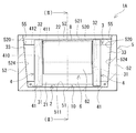
- FIG. 1 is a side view showing an outline of the reactor according to the first embodiment.
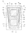
- FIG. 2 is a sectional view showing an outline of the reactor taken along the line (II)-(II) of FIG.
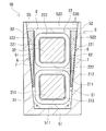
- FIG. 3 is a sectional view showing an outline of the reactor according to the second embodiment.
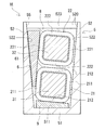
- FIG. 4 is a cross-sectional view showing the outline of the reactor according to the third embodiment.
- FIG. 5 is sectional drawing which shows the outline of the reactor which concerns on Embodiment 4.
- FIG. 6 is a sectional view showing the outline of the reactor according to the fifth embodiment.
- the space for installing the reactor may be so small that the pair of winding parts cannot be placed flat.
- stacking in the direction orthogonal to the installation surface may be referred to as vertical stacking.
- the distance between the side surface of the upper winding portion and the side wall portion of the case facing the side surface is smaller than that of the lower winding portion. It becomes larger than the distance between the side surface of the winding portion and the side wall portion of the case.
- the inner wall surface of the side wall portion of the case is usually formed with an inclined surface that is inclined from the inner bottom surface of the bottom plate portion of the case toward the opposite side so as to be away from each other at a distance facing each other.
- the case is typically manufactured by die casting such as die casting or injection molding.
- the inclined surface of the inner wall surface is formed by transferring a draft provided in the mold for releasing the case from the mold when the case is manufactured.
- the case for accommodating the pair of vertically stacked winding portions is deeper than the case for accommodating the pair of flatly arranged winding portions. The deeper the case, the larger the distance between the side surface of the upper winding part and the inner wall surface of the case.
- the gap between the side surface of the upper winding part and the inner wall surface of the case becomes large, so that the upper winding part is less likely to radiate through the inner wall surface of the case. That is, the lower winding portion is easily cooled, and the upper winding portion is difficult to cool. As a result, when the temperature of the upper winding portion becomes higher than that of the lower winding portion, the loss of the reactor increases.
- one of the purposes of the present disclosure is to provide a reactor with a small installation area and low loss.
- the reactor according to the present disclosure has a small installation area and low loss.
- a reactor according to an aspect of the present disclosure is A reactor comprising a combination of a coil and a magnetic core, a case that houses the combination, and a sealing resin portion that is filled inside the case and seals at least a part of the combination.
- a heat dissipation member interposed between the coil and the case The case is An inner bottom surface on which the combination is placed, A pair of coil facing surfaces facing the side surface of the coil, The pair of coil facing surfaces has an inclined surface that is inclined from the inner bottom surface side toward the opposite side of the inner bottom surface so as to be apart from each other,
- the coil is A first winding portion arranged on the inner bottom surface side, A second winding portion arranged on the side opposite to the inner bottom surface side of the first winding portion, The first winding portion and the second winding portion are vertically stacked so that their axes are parallel to each other, The first winding portion and the second winding portion have the same width
- the heat dissipation member has a first heat dissipation part interposed between at
- the installation area is smaller than that in the case where the first winding part and the second winding part are placed flat. small.
- the length of the combination along the direction orthogonal to both the parallel direction of the first winding part and the second winding part and the axial direction of the coil is such that the first winding part and the second winding part are This is because it is smaller than the length of the combination along the parallel direction of the parts.
- the above reactor has low loss. Since the first winding portion and the second winding portion have the same width, the distance between the one inclined surface and the one side surface of the second winding portion is equal to that of the one inclined surface and the first winding portion. Large compared to the spacing between one side of the part. However, the gap between the one inclined surface and the one side surface of the second winding portion can be filled with the first heat radiation portion. Therefore, the heat of the second winding portion is easily transferred to the coil facing surface of the case via the first heat radiating portion. Therefore, the first winding portion and the second winding portion are likely to be uniformly cooled via the coil facing surface of the case. The uniform cooling of the first winding portion and the second winding portion easily reduces the maximum temperature of the coil. Reducing the maximum coil temperature tends to reduce reactor loss. The definition of the width of the winding portion will be described later.
- the above reactor can reduce the cost.
- the second winding portion can be easily dissipated by interposing the heat dissipating member as described above, and thus the sealing resin portion does not have to be made of a resin having a high thermal conductivity or the like.
- a resin having a high thermal conductivity easily radiates heat from the second winding portion even if the distance between the side surface of the second winding portion and the inclined surface is large to some extent, but the cost is relatively high.
- the heat radiation member is used in a smaller amount than the sealing resin portion. Therefore, in the reactor, for example, even if the heat dissipation member is made of a resin having a high thermal conductivity, the cost is lower than that when the sealing resin portion is made of a resin having a high thermal conductivity.
- the first heat dissipation portion may have a length ranging from between the one inclined surface and the second winding portion to between the one inclined surface and the first winding portion.
- the above reactor makes it easier to radiate heat from the first winding part. This is because the gap between the one inclined surface and one side surface of the first winding portion is filled with a part of the first heat radiating portion.
- the gap between the one inclined surface and the one side surface of the first winding portion is smaller than the gap between the one inclined surface and the one side surface of the second winding portion. Therefore, even if a part of the first heat radiating portion is not interposed in the gap between the one inclined surface and the one side surface of the first winding portion, the first winding portion is provided via the coil facing surface of the case. Is easily dissipated.
- the heat of the first winding portion is transferred to the case via the first heat radiating portion. It is more easily transmitted to the coil facing surface.
- the heat dissipation member may include a second heat dissipation part interposed between the other inclined surface and the second winding part.
- the above reactor makes it easy to dissipate heat from the second winding part from both sides. This is because by having the second heat radiating portion, the heat of the second winding portion is easily transferred from both side surfaces of the second winding portion to the coil facing surface of the case.
- the second heat radiating portion may have a length ranging from between the other inclined surface and the second winding portion to between the other inclined surface and the first winding portion.
- the above reactor makes it easier to radiate heat from the first winding part. Since the gap between the other inclined surface and the other side surface of the first winding portion is filled with a part of the second heat radiation portion, the heat of the first winding portion is transferred to the coil of the case via the second heat radiation portion. This is because they are more easily transmitted to the facing surface.
- the heat dissipation member has a connecting part that is arranged on the side opposite to the first winding part side of the second winding part and connects the first heat dissipation part and the second heat dissipation part. .
- the first heat radiating portion and the second heat radiating portion are arranged at appropriate positions with respect to the second winding portion.
- the connecting portion By arranging the connecting portion on the side opposite to the first winding portion side of the second winding portion, the first heat radiating portion and the second heat radiating portion can be positioned at predetermined positions in the depth direction of the case. is there. Therefore, when the sealing resin portion is formed, the positional displacement of the first heat radiating portion and the second heat radiating portion due to the flow of the filling resin is easily suppressed.
- Examples of the positional deviation between the first heat radiating portion and the second heat radiating portion include sinking toward the inner bottom surface side of the case and moving along the axial direction of the winding portion.
- the connecting portion can handle the first heat radiating portion and the second heat radiating portion as one body, the workability of manufacturing the reactor can be improved. Furthermore, the connecting part can mechanically protect the second winding part and protect it from the external environment. The protection from the external environment improves the corrosion resistance of the second winding part.
- the inner bottom surface is a flat surface, Each end face shape of the first winding portion and the second winding portion, It has a rectangular frame shape, A pair of case facing sides that extend in the vertical direction and that face each of the inclined surfaces, A pair of connecting sides connecting one end side and the other end side of the pair of case facing sides, The pair of connecting sides may be parallel to the inner bottom surface.
- the distance between each side surface and each inclined surface of the first winding portion along the width direction gradually increases from the inner bottom surface side to the opposite side.
- the distance between each side surface and each inclined surface of the second winding portion along the width direction gradually increases from the inner bottom surface side to the opposite side.
- the distance between each inclined surface and each side surface of the second winding portion is larger than the distance between each inclined surface and each side surface of the first winding portion.
- the gap between the one inclined surface and the one side surface of the second winding portion can be filled with the first heat radiating portion, the heat of the second winding portion is transferred to the case via the first heat radiating portion. It is easily transmitted to the coil facing surface.
- the end surface shapes of the first winding portion and the second winding portion are It has a rectangular frame shape, One case facing side that is parallel to and faces one of the inclined surfaces, Having the other case facing side that is non-parallel and that faces the other inclined surface, The first heat dissipation part may be interposed between the other inclined surface and the other case facing side of the second winding part.
- the above reactor makes it easy to dissipate heat from the second winding part from both sides.
- the distance between the one side surface of the first winding portion and the one inclined surface can be made uniform from the inner bottom surface side to the opposite side.
- the distance between the one side surface and the one inclined surface of the second winding portion can be made uniform from the inner bottom surface side to the opposite side.
- the reactor described above makes the distance between the one side surface of the second winding portion and the one inclined surface uniform with the distance between the one side surface of the first winding portion and the one inclined surface. Because you can do it.
- one side surface of the second winding portion can be brought into surface contact with one inclined surface, if necessary.
- the interval along the width direction between the other side surface of the first winding portion and the other inclined surface gradually increases from the inner bottom surface side to the opposite side.
- the distance between the other side surface and the other inclined surface of the second winding portion along the width direction gradually increases from the inner bottom surface side to the opposite side.
- the heat dissipation member may include a protruding portion interposed between the first winding portion and the second winding portion.
- the projecting portion makes it easy to dispose the heat dissipation member at an appropriate position with respect to the second winding portion.
- the heat radiation member can be positioned at a predetermined position in the depth direction of the case by interposing the protruding portion between the first winding portion and the second winding portion. Therefore, when the sealing resin portion is formed, the displacement of the heat dissipation member due to the flow of the filling resin is easily suppressed. Examples of the displacement of the heat dissipation member include sinking toward the inner bottom surface of the case.
- the heat dissipation member is easy to assemble to the coil when manufacturing the reactor. Therefore, the reactor described above has excellent manufacturing workability.
- the thermal conductivity of the heat dissipation member is 1 W / mK or more.
- the above reactor is easy to radiate heat from the second winding part. Because the heat dissipation member has a high thermal conductivity, the heat of the second winding portion is easily transferred to the coil facing surface of the case via the heat dissipation member.
- the heat dissipation member is made of metal, It may be mentioned that an insulating member is provided between the heat radiation member and the second winding portion to insulate the heat radiation member and the second winding portion.
- the heat dissipation member is made of metal, so the second winding part can easily dissipate heat. By providing the insulating member, the insulating property between the second winding portion and the heat dissipation member is enhanced.
- An angle formed by the inner bottom surface and each of the inclined surfaces is 91 ° or more and 95 ° or less.
- the case is typically manufactured by die casting such as die casting or injection molding.
- the inclined surface is formed by transferring a draft provided in the mold for releasing the case from the mold when the case is manufactured. If the angle is 91 ° or more, the widths of the first winding portion and the second winding portion are the same, so when the first winding portion and the second winding portion are stacked vertically, The distance between the side surface of the second winding portion and the inclined surface is likely to be larger than the distance between the side surface and the inclined surface of the lower first winding portion.
- the gap between the side surface of the second winding portion on the upper stage side and the inclined surface is provided. Can be filled. Therefore, even in the case of vertical stacking, the second winding portion is likely to radiate heat through the side wall portion of the case. If the angle is 95 ° or less, the angle is not too large. Therefore, the width of the heat dissipation member does not become excessively large. Therefore, the size of the heat dissipation member is likely to be small, and the amount of the heat dissipation member used is reduced.
- the reactor 1 ⁇ / b> A includes a combined body 10 in which the coil 2 and the magnetic core 3 are combined, a case 5, a heat dissipation member 6, and a sealing resin portion 8.
- the case 5 includes a bottom plate portion 51 on which the combined body 10 is placed, and a side wall portion 52 that surrounds the outer periphery of the combined body 10.
- the pair of coil facing surfaces 521 facing the side surface of the coil 2 in the side wall portion 52 have inclined surfaces 522 that are inclined from the bottom plate portion 51 side toward the opposite side of the bottom plate portion 51 so as to be separated from each other.
- the heat dissipation member 6 is interposed between the coil 2 and the case 5.
- the sealing resin portion 8 is filled inside the case 5 and seals at least a part of the combined body 10.
- the coil 2 has a first winding portion 21 and a second winding portion 22 formed by winding a winding.
- the first winding portion 21 is arranged on the bottom plate portion 51 side.
- the second winding portion 22 is arranged on the side opposite to the bottom plate portion 51 side of the first winding portion 21.
- the first winding portion 21 and the second winding portion 22 are vertically stacked so that their axes are parallel to each other.
- the heat dissipation member 6 has a first heat dissipation part 61 interposed between at least one coil facing surface 521 (an inclined surface 522 described below) and the second winding part 22. is there.
- the following description will be made in the order of the main characteristic part of the reactor 1A, the structure of the part related to the characteristic part, the main effect, and each structure. Further, the following description will be given with the bottom plate portion 51 side of the case 5 as the bottom and the side opposite to the bottom plate portion 51 side as the top. That is, the direction along the vertical direction is the depth direction of the case 5. 1 and 2, the upper side of the paper surface is the upper side and the lower side of the paper surface is the lower side. The direction along this vertical direction is called the height direction or the vertical direction. The direction orthogonal to both the height direction and the axial direction of the coil 2 is called the width direction. In FIG. 2, the left-right direction of the paper surface is the width direction.
- the case 5 houses the combination 10 inside.
- the case 5 can protect the combination 10 mechanically and from the external environment. The protection from the external environment improves the corrosion resistance of the combination 10. Further, the case 5 can dissipate heat from the combined body 10.
- the case 5 is a bottomed cylindrical container.
- the case 5 includes a bottom plate portion 51 and a side wall portion 52. In FIG. 1, for convenience of explanation, the illustration of the side wall portion on the front side of the drawing is omitted.
- the bottom plate portion 51 and the side wall portion 52 are integrally formed in this example.
- the bottom plate portion 51 and the side wall portion 52 may be individually molded.
- the bottom plate portion 51 and the side wall portion 52 may be integrated with each other by screwing or the like.
- An opening 55 is formed on the upper end side of the side wall 52.
- the inner space surrounded by the bottom plate portion 51 and the side wall portion 52 has a shape and size capable of accommodating the entire combined body 10.
- the bottom plate portion 51 has an inner bottom surface 511 on which the combined body 10 is placed, and an outer bottom surface to be installed on an installation target such as a cooling base. Illustration of the installation target is omitted.
- the bottom plate portion 51 has a rectangular flat plate shape. The inner bottom surface 511 and the outer bottom surface are flat in this example.
- the side wall portion 52 surrounds the outer periphery of the combined body 10.
- the side wall portion 52 is provided upright on the peripheral edge of the bottom plate portion 51.
- the side wall 52 has a rectangular frame shape in this example.
- the height of the side wall portion 52 is higher than the height of the combined product 10.
- the inner wall surface 520 of the side wall portion 52 has four surfaces, a pair of coil facing surfaces 521 and a pair of core facing surfaces 523 (FIG. 1).
- the pair of coil facing surfaces 521 face each other.
- the pair of core facing surfaces 523 face each other.
- the facing direction of the pair of coil facing surfaces 521 and the facing direction of the pair of core facing surfaces 523 are orthogonal to each other.
- Each coil facing surface 521 faces the side surface of the coil 2. That is, each coil facing surface 521 faces the first winding portion 21 and the second winding portion 22.
- the side surfaces of the first winding part 21 and the second winding part 22 are the outer circumferences of the first winding part 21 and the second winding part 22 of the first winding part 21 and the second winding part 22, respectively.
- Each coil facing surface 521 has an inclined surface 522 that is inclined from the inner bottom surface 511 side of the case 5 toward the opening 55 side so as to be separated from each other.
- a groove portion into which the end surface member 41 is fitted may be formed at a position facing the end surface member 41 of the holding member 4 described later, in the depth direction of the case 5. Illustration of the groove is omitted. If the groove is formed, the combination 10 of the coil 2, the magnetic core 3 and the holding member 4 can be easily positioned with respect to the case 5.
- each core facing surface 523 faces the outer end surface of the outer core portion 33.
- the outer end surface of the outer core portion 33 is a surface of the outer core portion 33 opposite to the first inner core portion 31 and the second inner core portion 32.
- each core facing surface 523 has an inclined surface 524 that is inclined so as to be away from the inner bottom surface 511 side of the case 5 toward the opening 55 side.
- the case 5 is typically manufactured by die casting such as die casting or injection molding.
- the inclined surfaces 522 and 524 are formed by transferring the draft angle provided in the mold for releasing the case 5 from the mold when the case 5 is manufactured.
- the angle (angle ⁇ ) formed by each of the inclined surface 522 and the inclined surface 524 and the inner bottom surface 511 is preferably 91 ° or more and 95 ° or less (FIGS. 1 and 2). 1 and 2, the inclination angles of the inclined surface 522 and the inclined surface 524 are exaggerated for convenience of description.
- the angles formed by the inclined surface 522 and the inclined surface 524 and the inner bottom surface 511 are all the same in this example.
- the angle formed by the inclined surface 522 and the inner bottom surface 511 and the angle formed by the inclined surface 524 and the inner bottom surface 511 may be different from each other.
- the mold releasability of Case 5 is high. If the angle ⁇ is 91 ° or more, the widths of the first winding portion 21 and the second winding portion 22 are the same, so that the first winding portion 21 and the second winding portion 22 are mutually axial. When they are stacked in a direction orthogonal to the inner bottom surface 511 so that they are parallel to each other, the distance between the side surface of the second winding portion 22 on the upper stage side and the inclined surface 522 is equal to that of the first winding portion 21 on the lower stage side. It tends to be larger than the distance between the side surface and the inclined surface 522.
- the direction orthogonal to the inner bottom surface 511 is the depth direction of the case 5.
- stacking in the depth direction of the case 5 may be referred to as vertical stacking.
- the heat dissipation member 6 interposed in the gap between the side surface of the second winding portion 22 on the upper stage side and the inclined surface 522, the side surface and the inclined surface 522 of the second winding portion 22 on the upper stage side are provided.
- the gap between can be filled. Therefore, the second winding portion 22 is likely to radiate heat via the side wall portion 52 of the case 5 even if the above-mentioned products are stacked vertically.
- the angle ⁇ is 95 ° or less, the angle is not too large. Therefore, the width of the heat dissipation member 6 does not become excessively large. Therefore, since the size of the heat dissipation member 6 is likely to be small, the usage amount of the heat dissipation member 6 is reduced.
- Examples of the material of the case 5 include a non-magnetic metal and a non-metal material.
- the non-magnetic metal include aluminum and its alloys, magnesium and its alloys, copper and its alloys, silver and its alloys, and austenitic stainless steel. The thermal conductivity of these non-magnetic metals is relatively high. Therefore, the case 5 can be used as a heat dissipation path, and the heat generated in the combination 10 can be efficiently dissipated to an installation target such as a cooling base. Therefore, the reactor 1A can improve heat dissipation.
- die casting can be preferably used as a method of forming the case 5.
- non-metal material examples include resins such as polybutylene terephthalate (PBT) resin, urethane resin, polyphenylene sulfide (PPS) resin, and acrylonitrile-butadiene-styrene (ABS) resin.
- PBT polybutylene terephthalate
- PPS polyphenylene sulfide
- ABS acrylonitrile-butadiene-styrene
- the resin may contain a ceramics filler. Examples of the ceramic filler include alumina and silica. Resins containing these ceramic fillers are excellent in heat dissipation and electrical insulation.
- injection molding can be preferably used as a method of forming the case 5.
- the bottom plate portion 51 and the side wall portion 52 are individually molded, the bottom plate portion 51 and the side wall portion 52 may be made of different materials.
- the first winding portion 21 and the second winding portion 22 included in the coil 2 are hollow cylindrical bodies formed by spirally winding separate windings.
- the first winding portion 21 and the second winding portion 22 are rectangular tubular bodies.
- the first winding portion 21 and the second winding portion 22 can also be formed by a single winding.
- the first winding portion 21 and the second winding portion 22 are electrically connected to each other. The method of electrical connection will be described later.
- a covered wire having an insulating coating on the outer circumference of the conductor wire can be used.
- the material of the conductor wire include copper, aluminum, magnesium, and alloys thereof.
- Examples of the conductor wire include a rectangular wire and a round wire.
- Examples of the insulating coating include enamel.
- a typical example of the enamel is polyamide-imide.
- a coated rectangular wire whose conductor wire is a copper rectangular wire and whose insulating coating is enamel is used.
- the first winding part 21 and the second winding part 22 are constituted by an edgewise coil obtained by edgewise winding the coated rectangular wire.
- the cross-sectional areas of the windings of the first winding portion 21 and the second winding portion 22 are the same in this example.
- the first winding part 21 and the second winding part 22 are wound in the same direction.
- the first winding part 21 and the second winding part 22 have the same number of turns.
- the cross-sectional area and the number of turns of the windings of the first winding portion 21 and the second winding portion 22 may be different from each other.
- the first winding part 21 and the second winding part 22 are arranged vertically in the depth direction of the case 5 so that their axes are parallel to each other. This parallel does not include the same straight line.
- the first winding portion 21 is arranged on the bottom plate portion 51 side.
- the second winding portion 22 is arranged above the first winding portion 21, that is, on the side opposite to the bottom plate portion 51 side.
- the end face shapes of the first winding part 21 and the second winding part 22 are rectangular frame shapes (FIG. 2).
- the rectangular frame shape here includes a square frame shape.
- the corners of the first winding portion 21 and the second winding portion 22 are rounded.
- the end surface shapes of the first winding portion 21 and the second winding portion 22 may be trapezoidal frame shapes or the like. Examples of the trapezoidal frame shape include an isosceles trapezoidal frame shape and a right-angled trapezoidal frame shape.
- the end face shape of the first winding portion 21 has a pair of case facing sides 211 and a pair of connecting sides 212 (FIG. 2).
- the pair of case facing sides 211 face the inclined surfaces 522 of the coil facing surfaces 521 of the side wall portion 52.
- the pair of connecting sides 212 connects one end side and the other end side of the pair of case facing sides 211.
- the pair of case facing sides 211 are parallel to the depth direction of the case 5.
- Each connecting side 212 is parallel to the inner bottom surface 511 of the bottom plate portion 51.
- Each connecting side 212 extends along the width direction of the case 5.
- the end face shape of the second winding portion 22 has a pair of case facing sides 221 and a pair of connecting sides 222 (FIG. 2).
- the pair of case facing sides 221 face the inclined surfaces 522 of the coil facing surfaces 521 of the side wall portion 52.
- the pair of connecting sides 222 connects one end side and the other end side of the pair of case facing sides 221.
- the pair of case facing sides 221 are parallel to the depth direction of the case 5.
- Each connecting side 222 is parallel to the inner bottom surface 511 of the bottom plate portion 51.
- Each connection side 222 extends along the width direction of the case 5.
- the height and width of the first winding portion 21 and the second winding portion 22 are the same in this example. That is, the length of the pair of case facing sides 211 of the first winding portion 21 and the length of the pair of case facing sides 221 of the second winding portion 22 are the same. The length of the pair of connecting sides 212 in the first winding portion 21 and the length of the pair of connecting sides 222 in the second winding portion 22 are the same.
- the widths being the same means that the minimum widths of the second winding portion 22 and the first winding portion 21 are the same, It means that the maximum widths are the same.
- the heights of the first winding portion 21 and the second winding portion 22 may be different from each other.
- the distance between each side surface of the first winding portion 21 and each inclined surface 522 along the width direction gradually increases from the inner bottom surface 511 side to the opening 55 side.
- the distance between each side surface of the second winding portion 22 and each inclined surface 522 along the width direction gradually increases from the inner bottom surface 511 side to the opening 55 side.
- the minimum distance along the width direction between each side surface of the second winding portion 22 and each inclined surface 522 is equal to the minimum distance between each side surface of the first winding portion 21 and each inclined surface 522. Greater than maximum spacing. That is, the distance along the width direction between the inner bottom surface 511 side and each inclined surface 522 on each side surface of the second winding portion 22 is equal to the opening 55 side and each inclination on each side surface of the first winding portion 21. It is larger than the distance between the surface 522 and the width direction.
- the heat dissipation member 6 is interposed between the coil 2 and the case 5 (FIGS. 1 and 2).
- the heat dissipation member 6 can transfer the heat of the coil 2 to the case 5. 2, the thickness of the heat dissipation member 6 is exaggerated for convenience of description.
- the thickness of the heat dissipation member 6 is a length along the width direction. This point is the same in FIGS. 3 to 6 described later.
- the heat dissipation member 6 has at least a first heat dissipation portion 61 (on the left side of the paper surface of FIG. 2).
- the heat dissipation member 6 further includes a second heat dissipation portion 62 (on the right side of the paper surface of FIG. 2).
- the heat dissipation member 6 of this example has a second heat dissipation part 62 in addition to the first heat dissipation part 61.
- the first heat dissipation portion 61 is interposed between the one inclined surface 522 and the side surface of the second winding portion 22 (on the left side of the paper surface of FIG. 2).
- the first heat dissipation portion 61 fills a gap between the one inclined surface 522 and one side surface of the second winding portion 22. Therefore, the distance between the one inclined surface 522 and one side surface of the second winding portion 22 is smaller than the distance between the one inclined surface 522 and one side surface of the first winding portion 21. Even if large, the heat of the second winding portion 22 is easily transferred to the side wall portion 52 of the case 5 via the first heat radiating portion 61.
- the first winding portion 21 and the second winding portion 22 are likely to be uniformly cooled via the side wall portion 52 of the case 5. Even cooling of the first winding portion 21 and the second winding portion 22 facilitates reduction of the maximum temperature of the coil 2. By reducing the maximum temperature of the coil 2, the loss of the reactor 1A is easily reduced.
- the first heat radiation part 61 is made of a sheet-shaped member.
- the cross-sectional shape of the first heat dissipation portion 61 is preferably a shape that follows the shape of the gap between the one inclined surface 522 and one side surface of the second winding portion 22. This is because the first heat dissipation portion 61 easily fills the gap between the one inclined surface 522 and one side surface of the second winding portion 22.
- the cross-sectional shape of the first heat dissipation portion 61 is a right-angled trapezoid in this example.
- the thickness of the first heat dissipation part 61 gradually increases from the inner bottom surface 511 side toward the opening 55 side.
- the thickness of the first heat dissipation portion 61 is a length along the width direction.
- the surface of the first heat radiating portion 61 facing the second winding portion 22 is a flat surface parallel to the side surface of the second winding portion 22.
- the surface of the first heat radiating portion 61 facing the second winding portion 22 is in surface contact with the side surface of the second winding portion 22.
- the surface of the first heat dissipation portion 61 facing the inclined surface 522 is configured by a plane parallel to the inclined surface 522.
- the surface of the first heat dissipation portion 61 facing the inclined surface 522 is in surface contact with the inclined surface 522.
- the first heat radiating portion 61 and the second winding portion 22 are in surface contact with each other, and the first heat radiating portion 61 and the inclined surface 522 are in surface contact with each other.
- the heat of 22 is easily
- the height of the first heat radiating portion 61 preferably has a length extending from the upper end of the second winding portion 22 to the lower end of the second winding portion 22. The reason is that one side surface of the second winding portion 22 can be brought into contact with the first heat radiation portion 61 over the entire area in the height direction. Therefore, the heat of the second winding portion 22 is easily transferred to the side wall portion 52 of the case 5 via the first heat radiation portion 61.
- the height of the first heat dissipation portion 61 is a length along the depth direction.
- the lower end side of the first heat radiation part 61 may be located at the lower end of the second winding part 22 or may be located below the lower end of the second winding part 22. That is, the first heat dissipation portion 61 does not have to be interposed between the one inclined surface 522 and one side surface of the first winding portion 21, or the one inclination surface 522 and the first winding portion 21. It may be interposed between one of the side surfaces.
- the position on the lower end side of the first heat dissipation part 61 may be located at the lower end of the second winding part 22, but the thermal conductivity of the first heat dissipation part 61 is higher than that of the sealing resin part 8. Since it is large, it is preferably located below the lower end of the second winding portion 22. This is because the first winding portion 21 is more likely to dissipate heat.
- a gap between the one inclined surface 522 and one side surface of the first winding portion 21 can be filled with the lower end side of the first heat radiation portion 61. As described above, the gap between the one inclined surface 522 and the one side surface of the first winding portion 21 is the gap between the one inclined surface 522 and the one side surface of the second winding portion 22. Small in comparison.
- the first heat radiating portion 61 passes through the side wall portion 52 of the case 5 and then the first heat radiating portion 61.
- the winding part 21 can easily dissipate heat.
- the lower end side of the first heat radiating portion 61 is interposed between the one inclined surface 522 and one side surface of the first winding portion 21, the first winding portion 21 is interposed via the first heat radiating portion 61. Of heat is more easily transferred to the side wall portion 52 of the case 5.
- the height of the first heat radiation portion 61 has a length extending from the upper end of the second winding portion 22 to below the upper end of the first winding portion 21. Furthermore, it is preferable that the height of the first heat radiation portion 61 has a length extending from the upper end of the second winding portion 22 to the lower end of the first winding portion 21. In the present example, the height of the first heat dissipation portion 61 has a length extending from above the upper end of the second winding portion 22 to between the upper end and the lower end of the first winding portion 21.
- the length of the first heat radiating portion 61 is equal to the total length of the second winding portion 22 in the axial direction.
- the length of the first heat radiation portion 61 is a length along the axial direction of the second winding portion 22. Since the length of the first heat radiating portion 61 is the same as the total length of the second winding portion 22 in the axial direction, one side surface of the second winding portion 22 is formed over the substantially entire area in the axial direction. It is brought into contact with the heat dissipation portion 61. Therefore, the heat of the second winding portion 22 is easily transferred to the side wall portion 52 of the case 5 via the first heat radiation portion 61.
- the second heat dissipation portion 62 is interposed between the other inclined surface 522 and the other side surface of the second winding portion 22 (on the right side of the paper surface of FIG. 2). Since the heat dissipation member 6 has the second heat dissipation section 62, the heat of the second winding section 22 is transferred to the side wall section 52 of the case 5 from the other side surface of the second winding section 22 via the second heat dissipation section 62. Easy to be transmitted.
- This second heat dissipation part 62 can employ the same configuration as the first heat dissipation part 61.
- the material of the heat dissipation member 6 is preferably a material having a higher thermal conductivity than the sealing resin portion 8. Since the heat dissipation member 6 has a higher thermal conductivity than the sealing resin portion 8, the heat of the second winding portion 22 is easily transferred to the side wall portion 52 of the case 5.
- the thermal conductivity of the heat dissipation member 6 is preferably 1 W / mK or more, for example. When the thermal conductivity of the heat dissipation member 6 is 1 W / mK or more, the second winding portion 22 is likely to dissipate heat.
- the heat conductivity of the heat dissipation member 6 is preferably 3 W / mK or more, and particularly preferably 5 W / mK or more.
- the upper limit of the thermal conductivity of the heat dissipation member 6 is not particularly limited, but may be about 100 W / mK.
- Examples of the material of the heat dissipation member 6 include the same non-magnetic metal and non-metal material as the case 5.
- the magnetic core 3 includes a first inner core portion 31, a second inner core portion 32, and a pair of outer core portions 33 (FIG. 1).
- the first inner core portion 31 and the second inner core portion 32 are arranged inside the first winding portion 21 and the second winding portion 22, respectively.
- the first inner core portion 31 and the second inner core portion 32 mean portions of the magnetic core 3 along the axial direction of the first winding portion 21 and the second winding portion 22.
- both ends of the magnetic core 3 along the axial direction of the first winding part 21 and the second winding part 22 are located outside the first winding part 21 and the second winding part 22.
- the protruding portion is also a part of the first inner core portion 31 and the second inner core portion 32.
- the pair of outer core portions 33 are arranged outside the first winding portion 21 and the second winding portion 22. That is, in the outer core portion 33, the coil 2 is not arranged, but the outer core portion 33 is projected from the coil 2 and is exposed from the coil 2.
- the magnetic core 3 is formed in an annular shape by contacting the end surfaces of the first inner core portion 31 and the second inner core portion 32 with the inner end surface of the outer core portion 33. That is, the pair of outer core portions 33 are arranged so as to sandwich the first inner core portion 31 and the second inner core portion 32 which are arranged separately. The first inner core portion 31, the second inner core portion 32, and the pair of outer core portions 33 form a closed magnetic circuit when the coil 2 is excited.
- the shapes of the first inner core portion 31 and the second inner core portion 32 are preferably shapes along the inner peripheral shapes of the first winding portion 21 and the second winding portion 22. The reason is that it is easy to make the interval between the inner peripheral surface of the first winding portion 21 and the outer peripheral surface of the first inner core portion 31 uniform in the circumferential direction of the first inner core portion 31. The other reason is that it is easy to make the interval between the inner peripheral surface of the second winding portion 22 and the outer peripheral surface of the second inner core portion 32 uniform in the circumferential direction of the second inner core portion 32. .
- the shapes of the first inner core portion 31 and the second inner core portion 32 are rectangular parallelepiped.
- the corner portions of the first inner core portion 31 and the second inner core portion 32 are rounded along the inner peripheral surfaces of the corner portions of the first winding portion 21 and the second winding portion 22.
- the height of the first inner core portion 31 and the height of the second inner core portion 32 are the same in this example.
- the width of the first inner core portion 31 and the width of the second inner core portion 32 are the same. Therefore, the size of the gap between the inner peripheral surface of the first winding portion 21 and the outer peripheral surface of the first inner core portion 31, and the inner peripheral surface of the second winding portion 22 and the outer periphery of the second inner core portion 32.
- the size of the space between the surfaces is the same as each other.
- the first inner core portion 31 and the second inner core portion 32 of this example are composed of one columnar core piece.
- the core pieces do not go through the gap.
- the core piece has a length of substantially the entire axial length of the first winding portion 21 and the second winding portion 22.
- the first inner core portion 31 and the second inner core portion 32 may be configured by a laminated body in which a plurality of columnar core pieces and gaps are laminated and arranged along the axial direction of the coil 2.
- Examples of the shape of the outer core portion 33 include a rectangular parallelepiped shape and a quadrangular pyramid shape.
- the rectangular parallelepiped shape is a columnar body in which the outer end surface, the side surface, the upper surface, and the lower surface of the outer core portion 33 are all rectangular. The areas of the upper surface and the lower surface are the same.
- the quadrangular pyramid shape is, for example, a columnar body in which the outer end surface, the upper surface, and the lower surface of the outer core portion 33 are rectangular, and the side surfaces are rectangular trapezoidal.
- the area of the upper surface of the quadrangular pyramid-shaped outer core portion 33 is larger than the area of the lower surface.
- the outer core portion 33 in this example has a truncated pyramid shape.
- the outer core portion 33 may be a columnar body in which the outer end surface, the upper surface, and the lower surface have a rectangular shape, and the side surfaces have a right-angled trapezoidal shape (FIG. 1).
- the outer end surface of the outer core portion 33 is preferably configured as a surface parallel to the inclined surface 524 of the core facing surface 523. The reason is that the outer end surface of the outer core portion 33 and the inclined surface 524 of the core facing surface 523 can be brought into surface contact with each other. Due to this surface contact, the heat of the outer core portion 33 is easily transferred to the side wall portion 52 of the case 5. Therefore, the heat dissipation of the magnetic core 3 tends to be high. Moreover, the pair of outer core portions 33 can be pressed in the directions in which they approach each other. Therefore, the magnetic core 3 is less likely to be displaced with respect to the case 5.
- the upper surface of the outer core portion 33 is substantially flush with the upper surface of the second inner core portion 32 in this example.
- the lower surface of the outer core portion 33 is substantially flush with the lower surface of the first inner core portion 31 in this example.
- the upper surface of the outer core portion 33 may be higher than the upper surface of the second inner core portion 32.
- the lower surface of the outer core portion 33 may be below the lower surface of the first inner core portion 31.
- the sealing resin part 8 is filled in the case 5 and covers at least a part of the combined body 10.
- the sealing resin portion 8 transfers the heat of the combined body 10 to the case 5, mechanically protects the combined body 10 and protects it from the external environment, improves the corrosion resistance of the combined body 10, and between the combined body 10 and the case 5.
- Various functions such as improvement of the electric insulation property, integration of the combined body 10 and improvement of strength and rigidity of the reactor 1A by integrating the combined body 10 and the case 5.
- the encapsulating resin portion 8 of the present example embeds substantially the entire assembly 10.
- the sealing resin portion 8 has a portion interposed between the coil 2 and the case 5.
- the encapsulating resin portion 8 includes coils between the lower surface of the first winding portion 21 and the inner bottom surface 511 of the bottom plate portion 51, the lower side of each side surface of the first winding portion 21, and the side wall portion 52. It is interposed between the facing surface 521.
- the sealing resin portion 8 is also interposed between the upper surface of the first winding portion 21 and the lower surface of the second winding portion 22. The heat of the first winding portion 21 is transferred to the case 5 via the sealing resin portion 8.
- thermosetting resin and the thermoplastic resin may be used as the material of the sealing resin portion 8.
- thermosetting resin include epoxy resin, urethane resin, silicone resin, unsaturated polyester resin and the like.
- thermoplastic resin include PPS resin and the like. These resins may contain the above-mentioned ceramic filler and the like.
- the reactor 1A according to the first embodiment can achieve the following effects.
- the length of the combined body 10 along the direction orthogonal to both the parallel direction of the first winding portion 21 and the second winding portion 22 and the axial direction of the coil 2 is determined by the length of the first winding portion 21 and the second winding portion. This is because it is smaller than the length of the combined product 10 along the parallel direction of the turning portions 22.
- the gap between the one inclined surface 522 and one side surface of the second winding portion 22 can be filled with the first heat radiation portion 61. Further, the gap between the other inclined surface 522 and the other side surface of the second winding portion 22 can be filled with the second heat radiation portion 62. Therefore, even if the distance between each inclined surface 522 and each side surface of the second winding portion 22 is larger than the distance between each inclined surface 522 and each side surface of the first winding portion 21, The heat of the second winding portion 22 is easily transferred to the side wall portion 52 of the case 5 from both side surfaces of the second winding portion 22 via the first heat radiation portion 61 and the second heat radiation portion 62.
- the second winding portion 22 since the second winding portion 22 is easily radiated, the first winding portion 21 and the second winding portion 22 are likely to be uniformly cooled via the side wall portion 52 of the case 5. Even cooling of the first winding portion 21 and the second winding portion 22 facilitates reduction of the maximum temperature of the coil 2. By reducing the maximum temperature of the coil 2, the loss of the reactor 1A is easily reduced.
- the conductors at the ends on the one end side of the coil 2 in the axial direction are directly connected to each other.
- the conductors are connected by bending the ends of the winding of the first winding part 21 and extending to the ends of the winding of the second winding part 22.
- the conductors may be connected to each other via a connecting member that is independent of the first winding portion 21 and the second winding portion 22.
- the connecting member is made of, for example, the same member as the winding.
- the conductors can be connected by welding or pressure welding.
- both ends of each winding on the other end side in the axial direction of the coil 2 are extended upward from the opening 55 of the case 5, although not shown.
- the insulating coating is peeled off to expose the conductor.
- a terminal member is connected to the exposed conductor.
- the coil 2 is connected to an external device such as a power source for supplying electric power to the coil 2 via the terminal member. Illustration of the terminal member and the external device is omitted.
- the first winding part 21 and the second winding part 22 may be individually integrated by an integrated resin. Illustration of the integrated resin is omitted.
- the integrated resin covers the outer peripheral surface, the inner peripheral surface, and the end surface of the first winding portion 21 and the second winding portion 22, and joins adjacent turns.
- a resin having a coating layer of heat-sealing resin formed on the outer circumference of the winding is used, and the winding can be wound and then heated to melt the coating layer.
- the outer circumference of the winding refers to a further outer circumference of the insulating coating of the winding.
- the heat fusion resin include thermosetting resins such as epoxy resin, silicone resin and unsaturated polyester.
- the first inner core portion 31, the second inner core portion 32, and the outer core portion 33 are made of a powder compact or a composite material.
- the powder compact is formed by compression molding soft magnetic powder.
- the powder compact can have a higher proportion of the soft magnetic powder in the core piece as compared with the composite material. Therefore, the green compact is easy to enhance the magnetic properties.
- the magnetic characteristics include relative permeability and saturation magnetic flux density.
- the composite material is formed by dispersing soft magnetic powder in resin.
- the composite material can be obtained by filling a mold with a fluid material in which soft magnetic powder is dispersed in an unsolidified resin and curing the resin.
- the composite material can easily adjust the content of the soft magnetic powder in the resin. Therefore, the composite material is easy to adjust the magnetic characteristics.
- the composite material is easier to form even in a complicated shape as compared with the powder compact.
- the first inner core portion 31, the second inner core portion 32, and the outer core portion 33 may be a hybrid core in which the outer periphery of the powder compact is covered with the composite material.
- the first inner core portion 31 and the second inner core portion 32 are made of a composite material.
- the pair of outer core portions 33 are formed of a powder compact.
- the soft magnetic powder particles include soft magnetic metal particles, coated particles having an insulating coating around the soft magnetic metal particles, and soft magnetic non-metal particles.
- soft magnetic metals include pure iron and iron-based alloy gold.
- iron-based alloys include Fe-Si alloys and Fe-Ni alloys.
- soft magnetic non-metals include ferrite.
- a thermosetting resin or a thermoplastic resin can be used as the resin of the composite material.
- the thermosetting resin include epoxy resin, phenol resin, silicone resin and urethane resin.
- the thermoplastic resin include PPS resin, polyamide (PA) resin, liquid crystal polymer (LCP), polyimide resin, and fluororesin.
- PA resin include nylon 6, nylon 66, nylon 9T and the like. These resins may contain the above-mentioned ceramics filler.
- the gap is made of a material having a smaller relative magnetic permeability than the first inner core portion 31, the second inner core portion 32, and the outer core portion 33.
- the relative magnetic permeability of the first inner core portion 31 and the second inner core portion 32 is preferably 5 or more and 50 or less, more preferably 10 or more and 30 or less, and particularly preferably 20 or more and 30 or less.
- the relative magnetic permeability of the outer core portion 33 preferably satisfies at least twice the relative magnetic permeability of the first inner core portion 31 and the second inner core portion 32.
- the relative magnetic permeability of the outer core portion 33 is preferably 50 or more and 500 or less.
- the combined body 10 may include the holding member 4 (FIG. 1).
- the holding member 4 ensures insulation between the coil 2 and the magnetic core 3.
- the holding member 4 of this example has a pair of end surface members 41.
- the end surface member 41 ensures insulation between each end surface of the coil 2 and each outer core portion 33.
- the shape of each end surface member 41 is the same.
- Each end surface member 41 is a frame-shaped plate member in which two through holes 410 are provided along the stacking direction of the first winding portion 21 and the second winding portion 22. The respective ends of the first inner core portion 31 and the second inner core portion 32 are fitted into the respective through holes 410.
- Two recesses 411 for accommodating the end faces of the first winding portion 21 and the second winding portion 22 are formed on the coil 2 side surface of each end surface member 41.
- Each of the recesses 411 on the coil 2 side makes the entire end surfaces of the first winding portion 21 and the second winding portion 22 come into surface contact with the end surface member 41.
- Each recess 411 is formed in a rectangular ring shape so as to surround the through hole 410.
- the holding member 4 may further include an inner member.
- the inner member ensures insulation between the inner peripheral surfaces of the first winding portion 21 and the second winding portion 22 and the outer peripheral surfaces of the first inner core portion 31 and the second inner core portion 32.
- Examples of the material of the holding member 4 include insulating materials such as various resins.
- the resin for example, the same resin as the resin of the composite material described above can be used.
- the other thermoplastic resin include polytetrafluoroethylene (PTFE) resin, PBT resin, ABS resin and the like.
- PTFE polytetrafluoroethylene
- other thermosetting resins include unsaturated polyester resins.
- the material of the holding member 4 is preferably the same as that of the sealing resin portion 8. This is because the holding member 4 and the sealing resin portion 8 can have the same linear expansion coefficient, and damage to each member due to thermal expansion and contraction can be suppressed.
- the combination 10 may include a mold resin portion.
- the mold resin portion covers each outer core portion 33 and extends inside the first winding portion 21 and the second winding portion 22.
- the mold resin portion covers a region of the outer peripheral surface of each outer core portion 33, excluding a connecting surface between the first inner core portion 31 and the second inner core portion 32.
- the mold resin portion is formed between each outer core portion 33 and the recess 412 of each end surface member 41, the outer peripheral surfaces of the first inner core portion 31 and the second inner core portion 32, and the through hole 410 of each end surface member 41. And the inner peripheral surfaces of the first winding portion 21 and the second winding portion 22 and the outer peripheral surfaces of the first inner core portion 31 and the second inner core portion 32.
- This mold resin portion can integrate each outer core portion 33, each end surface member 41, first inner core portion 31, second inner core portion 32, first winding portion 21, and second winding portion 22.
- the material of the mold resin portion for example, the same thermosetting resin or thermoplastic resin as the resin of the composite material described above can be used.
- These resins may contain the above-mentioned ceramics filler. The inclusion of the ceramics filler can improve the heat dissipation of the mold resin portion.
- the reactor 1A can be used as a component of a circuit that performs a voltage boosting operation or a voltage dropping operation.
- the reactor 1A can be used as, for example, various converters, components of a power conversion device, or the like.
- the converter include a vehicle-mounted converter mounted in a vehicle such as a hybrid vehicle, a plug-in hybrid vehicle, an electric vehicle, a fuel cell vehicle, and a converter for an air conditioner.
- a DC-DC converter is typically used as the in-vehicle converter.
- FIG. 3 is a sectional view showing a state in which the reactor 1B is cut at the same position as the sectional view shown in FIG.
- the insulating member 7 insulates the heat dissipation member 6 from the second winding portion 22. That is, the insulating member 7 insulates each of the first heat radiation part 61 and the second heat radiation part 62 from the second winding part 22.
- the heat radiation member 6 and the second winding portion 22 can be insulated by the insulating coating of the winding of the second winding portion 22, the insulating property can be further improved by providing the insulating member 7.
- the material of the insulating member 7 may be the same non-metallic material as the case 5.
- the insulating member 7 may be formed integrally with the heat dissipation member 6 or may be configured as a separate member from the heat dissipation member 6. In this example, the insulating member 7 is formed integrally with the heat dissipation member 6.
- the covering area of the insulating member 7 may be an area facing the second winding section 22 in the first heat radiating section 61 and the second heat radiating section 62.
- the insulating member 7 includes the first heat radiating portion 61 and the second heat radiating portion 62. It is also preferably formed in a region facing the first winding portion 21 in. Then, the insulation between the heat dissipation member 6 and the first winding portion 21 becomes high.
- the thickness of the insulating member 7 is preferably as thin as possible as long as the insulating property can be improved. This is because even if the insulating member 7 is provided, the heat of the second winding portion 22 can be easily transmitted to the side wall portion 52 of the case 5 via the heat dissipation member 6.
- the thickness of the insulating member 7 is the length along the width direction.
- the thickness of the insulating member 7 is preferably 0.1 mm or more, for example. If the thickness of the insulating member 7 is 0.1 mm or more, it is easy to improve the insulating property.
- the thickness of the insulating member 7 is preferably 2.0 mm or less, for example. If the thickness of the insulating member 7 is 2.0 mm or less, it is easy to radiate heat from the second winding portion 22.
- the thickness of the insulating member 7 is more preferably 1.0 mm or less, and particularly preferably 0.5 mm or less.
- the second winding portion 22 can easily dissipate heat from both side surfaces thereof. Since the first heat radiating portion 61 and the second heat radiating portion 62 are each made of metal, the second winding is performed from both side surfaces of the second winding portion 22 via the first heat radiating portion 61 and the second heat radiating portion 62. This is because the heat of the turning portion 22 is easily transferred to the side wall portion 52 of the case 5. In addition, the first heat radiation portion 61 and the second heat radiation portion 62 are easily insulated from the coil 2. This is because the insulating member 7 is formed in the area facing the coil 2 in the first heat radiating portion 61 and the second heat radiating portion 62.
- FIG. 4 is a sectional view showing a state in which the reactor 1C is cut at the same position as the sectional view shown in FIG.
- Each protrusion 611, 621 is interposed between the first winding portion 21 and the second winding portion 22. It is easy for the protrusions 611 and 621 to dispose the first heat radiating portion 61 and the second heat radiating portion 62 at appropriate positions with respect to the second winding portion 22. The reason is that the protrusions 611 and 621 are interposed between the first winding portion 21 and the second winding portion 22, so that the first heat radiating portion 61 and the second heat radiating portion 62 are deep in the case 5. This is because it can be positioned at a predetermined position in the vertical direction.
- the sealing resin portion 8 when the sealing resin portion 8 is formed, the positional displacement between the first heat radiating portion 61 and the second heat radiating portion 62 due to the flow of the filling resin is easily suppressed.
- the positional displacement between the first heat dissipation part 61 and the second heat dissipation part 62 may be, for example, sinking toward the inner bottom surface 511 side of the case 5.
- the first heat radiating portion 61 and the second heat radiating portion 62 are easy to assemble to the coil 2 when manufacturing the reactor 1C. Therefore, the reactor 1C has excellent manufacturing workability.
- Each of the projecting portions 611 and 621 is formed so as to project toward the coil 2 side from the surface of the first heat radiating portion 61 and the second heat radiating portion 62 facing the coil 2.
- Each of the protrusions 611 and 621 may be formed by a protrusion formed continuously along the longitudinal direction thereof, or may be formed by a plurality of protrusions.
- the plurality of protruding pieces may be provided at intervals in the axial direction of the second winding portion 22.
- the constituent resin of the sealing resin portion 8 easily flows in the vertical direction of the case 5 through the gap between the protruding pieces.
- each protrusion 611, 621 is, for example, triangular, rectangular, semicircular, mountain-shaped having curved surfaces along both corners of the first winding portion 21 and the second winding portion 22. Can be mentioned. If the projecting portions 611 and 621 have a mountain-shaped cross-section, the projecting portions 611 and 621 can be closely attached to both corners of the first winding portion 21 and the second winding portion 22. Therefore, more effective heat dissipation of the second winding portion 22 can be expected.
- the cross-sectional shape of the protrusions 611 and 621 is a right-angled triangle that tapers toward the tip side in this example.
- the lower side is parallel to the connecting side 212 of the first winding portion 21, and the upper side is the inclined side. Since the lower side is parallel to the connecting side 212, the lower side can be pressed against the first winding portion 21. Therefore, when the sealing resin portion 8 is formed, it is easy to prevent the first heat radiation portion 61 and the second heat radiation portion 62 from sinking to the inner bottom surface 511 side of the case 5 by pouring the resin from the opening portion 55 side of the case 5. .
- the right triangle may have an upper side parallel to the connecting side 222 of the second winding portion 22 and a lower side as an inclined side. Since the upper side is parallel to the connecting side 222, the upper side can be stopped by hitting the second winding portion 22. Therefore, when the sealing resin part 8 is formed, it is easy to prevent the first heat radiating part 61 and the second heat radiating part 62 from floating toward the opening 55 side of the case 5 due to an increase in the volume of the filling resin in the case 5.
- each protruding portion 611, 621 is preferably 50% or more of the axial length of the second winding portion 22. The reason is that the first heat radiating portion 61 and the second heat radiating portion 62 are less likely to be displaced with respect to the second winding portion 22.
- the length of each protrusion 611, 621 is the length along the axial direction of the second winding portion 22. It is preferable that the length of each of the protrusions 611 and 621 is 75% or more of the axial length of the second winding portion 22. It is preferable to have a length equivalent to the total length.
- the length of each protrusion 611, 621 means the total length of the plurality of protrusions along the axial direction of the second winding portion 22.
- an insulating member 7 may be provided at the contact portion of the protrusions 611 and 621 with the coil 2.
- the protrusions 611 and 621 are made of metal, the insulation between the protrusions 611 and 621 and the coil 2 can be improved.
- the reactor 1C can be manufactured as follows. The assembly in which the heat dissipation member 6 is assembled to the combined body 10 is housed in the case 5. Then, the constituent resin of the sealing resin portion 8 is filled in the case 5 and cured. By assembling the heat dissipation member 6 to the combination body 10 before housing the combination body 10 in the case 5, it is easy to interpose the heat dissipation member 6 between the inclined surface 522 of the case 5 and the second winding portion 22.
- the second winding portion 22 can easily dissipate heat from both side surfaces thereof. Since the first heat radiating portion 61 and the second heat radiating portion 62 have the projecting portions 611 and 621, respectively, the first heat radiating portion 61 and the second heat radiating portion 62 are arranged at proper positions with respect to the second winding portion 22. This is because it is easy to do. Therefore, the heat of the second winding portion 22 is easily transferred to the side wall portion 52 of the case 5 from both side surfaces of the second winding portion 22 via the first heat radiation portion 61 and the second heat radiation portion 62.
- FIG. 5 is a cross-sectional view showing a state in which the reactor 1D is cut at the same position as the cross-sectional view shown in FIG.
- the connecting portion 63 connects the upper ends of the first heat radiating portion 61 and the second heat radiating portion 62 to each other.
- the connecting portion 63 is arranged on the upper surface of the second winding portion 22, that is, on the side of the second winding portion 22 opposite to the first winding portion 21 side.
- This connecting portion 63 facilitates disposing the first heat radiating portion 61 and the second heat radiating portion 62 at appropriate positions with respect to the second winding portion 22.
- the reason is that by disposing the connecting portion 63 on the upper surface of the second winding portion 22, the first heat radiating portion 61 and the second heat radiating portion 62 can be positioned at predetermined positions in the depth direction of the case 5. is there.
- the sealing resin portion 8 when the sealing resin portion 8 is formed, the positional displacement of the first heat radiating portion 61 and the second heat radiating portion 62 due to the flow of the filling resin is easily suppressed.
- Examples of the positional deviation between the first heat radiating portion 61 and the second heat radiating portion 62 include sinking toward the inner bottom surface 511 side of the case 5 and movement along the axial direction of the second winding portion 22. . Since the first heat radiating portion 61 and the second heat radiating portion 62 can be handled as one body by the connecting portion 63, the reactor 1D can be improved in workability in manufacturing.
- the connecting portion 63 can also mechanically protect the upper surface of the second winding portion 22 and protect it from the external environment. The protection from the external environment improves the corrosion resistance of the second winding portion 22.
- the connecting part 63 is made of a sheet-shaped member.
- the cross-sectional shape of the connecting portion 63 is rectangular.
- the thickness of the connecting portion 63 is uniform in the width direction.
- the thickness of the connecting portion 63 is a length along the height direction.
- the length of the connecting portion 63 along the axial direction of the second winding portion 22 is preferably equal to the total length of the second winding portion 22 in the axial direction. This is because the upper surface of the second winding portion 22 can be covered with the connecting portion 63 over substantially the entire area.
- the insulating member 7 may be provided on the lower surface of the connecting portion 63 at the contact point with the second winding portion 22.
- the connecting portion 63 may be composed of a plurality of bars or a plurality of plates that bridge the first heat radiating portion 61 and the second heat radiating portion 62.
- the plurality of rods and the plurality of plates may be arranged at intervals in the axial direction of the second winding portion 22. It is easy for the constituent resin of the sealing resin portion 8 to fill the inner bottom surface 511 side of the case 5 through the gap between the rod members or the plate members.
- the reactor 1D may have a fixing portion that fixes the connecting portion 63 to the case 5. Illustration of the fixed part is omitted. If the fixing portion is provided, the displacement of the connecting portion 63 with respect to the case 5 is prevented by the flow of the filling resin when the sealing resin portion 8 is formed.
- the second winding portion 22 can easily dissipate heat from both side surfaces thereof.
- the reason is that by having the connecting portion 63, the first heat radiating portion 61 and the second heat radiating portion 62 can be easily arranged at appropriate positions with respect to the second winding portion 22. Therefore, the heat of the second winding portion 22 is easily transferred to the side wall portion 52 of the case 5 from both side surfaces of the second winding portion 22 via the first heat radiation portion 61 and the second heat radiation portion 62.
- a reactor 1E according to the fifth embodiment will be described with reference to FIG.
- the reactor 1E according to the fifth embodiment includes the first winding portion so that one side surface (the right side in FIG. 6) of the first winding portion 21 and the second winding portion 22 and one inclined surface 522 are in surface contact with each other. 21 and the second winding portion 22 are arranged so as to be inclined, and the heat radiation member 6 includes only the first heat radiation portion 61, which is different from the reactor 1A according to the first embodiment.
- FIG. 6 is a cross-sectional view showing a state in which reactor 1E is cut at the same position as the cross-sectional view shown in FIG.
- One case facing side 211 of the first winding portion 21 is parallel to the one inclined surface 522.
- the other case facing side 211 of the first winding portion 21 is not parallel to the other inclined surface 522.
- the pair of connecting sides 212 of the first winding portion 21 is not parallel to the inner bottom surface 511.
- the pair of connecting sides 212 is orthogonal to the one inclined surface 522 and intersects the other inclined surface 522 in a non-orthogonal manner.
- one case facing side 221 of the second winding portion 22 is parallel to the one inclined surface 522.
- the other case facing side 221 of the second winding portion 22 is not parallel to the other inclined surface 522.
- the pair of connecting sides 222 of the second winding portion 22 is not parallel to the inner bottom surface 511.
- the pair of connecting sides 222 is orthogonal to the one inclined surface 522 and intersects the other inclined surface 522 in a non-orthogonal manner.
- the length of the pair of case facing sides 211 of the first winding portion 21 and the length of the pair of case facing sides 221 of the second winding portion 22 are the same.
- the length of the pair of connecting sides 212 in the first winding portion 21 and the length of the pair of connecting sides 222 in the second winding portion 22 are the same.
- the space between the one side surface of the first winding portion 21 and the one inclined surface 522 can be made uniform from the inner bottom surface 511 side to the opening 55 side (the right side of the drawing of FIG. 6).
- the distance between the one side surface of the second winding portion 22 and the one inclined surface 522 can be made uniform from the inner bottom surface 511 side to the opening 55 side.
- the distance between the one side surface of the first winding portion 21 and the one inclined surface 522 and the distance between the one side surface of the second winding portion 22 and the one inclined surface 522 are mutually uniform. Can be Therefore, the first winding portion 21 and the second winding portion 22 are likely to be uniformly cooled via the side wall portion 52 of the case 5.
- one side surface of the first winding portion 21 and one side surface of the second winding portion 22 are in surface contact with one inclined surface 522 (on the right side of the paper surface of FIG. 6). Therefore, the first winding part 21 and the second winding part 22 are more easily cooled.
- a space is provided between one side surface of the first winding portion 21 and the second winding portion 22 and the one inclined surface 522.
- One side surface of the two-winding portion 22 and one inclined surface 522 are in direct contact with each other.
- the other side surface of the first winding part 21 and the other side surface of the second winding part 22 are not in contact with the other inclined surface 522 (the left side of the paper surface of FIG. 6).
- a predetermined space is provided between the other side surface of the first winding portion 21 and the other inclined surface 522 and between the other side surface of the second winding portion 22 and the other inclined surface 522. ing.
- the distance between the other side surface of the first winding portion 21 and the other inclined surface 522 gradually increases from the inner bottom surface 511 side to the opening 55 side.
- the distance between the other side surface of the second winding portion 22 and the other inclined surface 522 gradually increases from the inner bottom surface 511 side to the opening 55 side.
- the minimum distance along the width direction between the other side surface of the second winding portion 22 and the other inclined surface 522 is the other side surface of the first winding portion 21 and the other side surface. Is larger than the maximum distance between the inclined surface 522 and the inclined surface 522 in the width direction. That is, the distance along the width direction between the inner bottom surface 511 side and the other inclined surface 522 on the other side surface of the second winding portion 22 is the opening 55 side on the other side surface of the first winding portion 21. And the other inclined surface 522 is larger than the interval along the width direction.
- the 1st heat dissipation part 61 is interposed in the clearance gap between the other inclined surface 522 and the other side surface of the 2nd winding part 22 (left side of the paper surface of FIG. 6).
- the first heat radiation portion 61 is in surface contact with each of the other inclined surface 522 and the other side surface of the second winding portion 22. Therefore, the heat of the second winding portion 22 is easily transferred to the side wall portion 52 of the case 5 also from the other side surface of the second winding portion 22. Therefore, the first winding portion 21 and the second winding portion 22 are likely to be uniformly cooled via the side wall portion 52 of the case 5.
- An insulating member 7 (FIG.
- the 1st heat dissipation part 61 may have the protrusion part 611 (FIG. 4).
- the material of the first heat dissipation portion 61 is as described in the first embodiment.
- the reactor 1B preferably includes a pedestal portion 9.
- the pedestal portion 9 is arranged on the inner bottom surface 511 of the bottom plate portion 51.
- the pedestal portion 9 mounts the first winding portion 21 and the second winding portion 22 in an inclined state with respect to the inner bottom surface 511 of the bottom plate portion 51.
- the pedestal part 9 makes one case facing side 211 of the first winding part 21 and one case facing side 221 of the second winding part 22 parallel to the one inclined surface 522. That is, the upper surface of the pedestal portion 9 of this example is a surface along the direction orthogonal to the one inclined surface 522.
- the pedestal portion 9 of this example is composed of a member different from the case 5.
- the pedestal portion 9 is composed of a sheet-shaped member that supports substantially the entire lower surface of the first winding portion 21.
- the sectional shape of the pedestal portion 9 is a right-angled trapezoid.
- the upper surface of the pedestal portion 9 is formed as an inclined surface.
- the height of the pedestal portion 9 gradually increases from one inclined surface 522 side toward the other inclined surface 522 side.
- the pedestal portion 9 may be configured by a ridge member that supports one end side in the width direction on the lower surface of the first winding portion 21 in the axial direction of the first winding portion 21.
- the pedestal portion 9 can be configured by a part of the case 5.
- the inner bottom surface 511 may be formed of the inclined surface.
- the same non-magnetic metal or non-metallic material as that of the case 5 can be mentioned. If the pedestal portion 9 is made of these materials, the heat of the first winding portion 21 is easily transferred to the bottom plate portion 51 of the case 5 via the pedestal portion 9. Therefore, the first winding portion 21 is easily cooled.
- the pedestal portion 9 may be made of a non-magnetic metal sheet coated with a non-metal material. Then, the insulation between the first winding portion 21 and the case 5 tends to be high.
- the second winding portion 22 can easily dissipate heat from both side surfaces thereof. This is because by tilting the first winding part 21 and the second winding part 22, one side surface of the second winding part 22 and one inclined surface 522 are in surface contact with each other. In addition, by interposing the first heat dissipation portion 61 between the other inclined surface 522 and the other side surface of the second winding portion 22, the second winding portion 22 is also wound from the other side surface. This is because the heat of the portion 22 is easily transferred to the side wall portion 52 of the case 5.
Abstract
A reactor that comprises: an assembly of a coil and a magnetic core; a case that houses the assembly thereinside; a sealing resin part that packs the inside of the case and seals at least a portion of the assembly; and a heat dissipation member that is interposed between the coil and the case. The case has: an inside bottom surface on which the assembly is mounted; and a pair of coil-facing surfaces that face side surfaces of the coil. The pair of coil-facing surfaces have inclined surfaces that are inclined so as to separate from each other from the inside bottom surface side toward the side opposite the inside bottom surface. The coil comprises: a first wound part that is arranged on the inside bottom surface side; and a second wound part that is arranged on the opposite side of the first wound part from the inside bottom surface side. The first wound part and the second wound part are vertically stacked such that the axes thereof are parallel. The first wound part and the second wound part have the same width. The heat dissipation member has a first heat dissipation part that is interposed between at least one of the inclined surfaces and the second wound part.
Description
本開示は、リアクトルに関する。
本出願は、2018年10月26日付の日本国出願の特願2018-202371に基づく優先権を主張し、前記日本国出願に記載された全ての記載内容を援用するものである。 The present disclosure relates to reactors.
This application claims priority based on Japanese Patent Application No. 2018-202371 filed on October 26, 2018 in Japan, and incorporates all the contents described in the Japanese application.
特許文献1のリアクトルは、コイルと磁性コアとの組合体と、ケースと、封止樹脂部とを備える。ケースは、組合体を内部に収納する。このケースは、組合体が載置される底板部と、組合体の外周を囲む側壁部とを有する。底板部と側壁部とは、一体に成形されている。コイルは、一対の巻回部を有する。一対の巻回部の形状は、互いに矩形状である。一対の巻回部の幅及び高さは、互いに同一である。この一対の巻回部は、互いの軸が平行となるように底板部の同一平面上に横並びに配置されている。以下の説明では、同一平面上に横並びに配置することを平置きということがある。磁性コアは、各巻回部の内部に配置される内側コア部と、各巻回部の外部に配置される外側コア部とを有する。封止樹脂部は、ケースの内部に充填され、組合体を封止する。
The reactor of Patent Document 1 includes a combination of a coil and a magnetic core, a case, and a sealing resin portion. The case accommodates the combination inside. This case has a bottom plate portion on which the combination is placed and a side wall portion surrounding the outer periphery of the combination. The bottom plate portion and the side wall portion are integrally formed. The coil has a pair of winding parts. The shape of the pair of winding portions is a rectangular shape. The width and height of the pair of winding portions are the same. The pair of winding portions are arranged side by side on the same plane of the bottom plate portion so that their axes are parallel to each other. In the following description, horizontal placement on the same plane may be referred to as flat placement. The magnetic core has an inner core portion arranged inside each winding portion and an outer core portion arranged outside each winding portion. The sealing resin portion is filled inside the case to seal the combined body.
本開示に係るリアクトルは、
コイルと磁性コアとの組合体と、前記組合体を内部に収納するケースと、前記ケースの内部に充填されて前記組合体の少なくとも一部を封止する封止樹脂部とを備えるリアクトルであって、
前記コイルと前記ケースとの間に介在される放熱部材を備え、
前記ケースは、
前記組合体を載置する内底面と、
前記コイルの側面に対向する一対のコイル対向面とを有し、
前記一対のコイル対向面は、前記内底面側から前記内底面の反対側に向かって互いの距離が離れるように傾斜する傾斜面を有し、
前記コイルは、
前記内底面側に配置される第一巻回部と、
前記第一巻回部の前記内底面側とは反対側に配置される第二巻回部とを備え、
前記第一巻回部と前記第二巻回部とは、互いの軸が平行となるように縦積みされ、
前記第一巻回部と前記第二巻回部の幅が互いに同一であり、
前記放熱部材は、少なくとも一方の前記傾斜面と前記第二巻回部との間に介在される第一放熱部を有する。 The reactor according to the present disclosure is
A reactor comprising a combination of a coil and a magnetic core, a case that houses the combination, and a sealing resin portion that is filled inside the case and seals at least a part of the combination. hand,
A heat dissipation member interposed between the coil and the case,
The case is
An inner bottom surface on which the combination is placed,
A pair of coil facing surfaces facing the side surface of the coil,
The pair of coil facing surfaces has an inclined surface that is inclined from the inner bottom surface side toward the opposite side of the inner bottom surface so as to be apart from each other,
The coil is
A first winding portion arranged on the inner bottom surface side,
A second winding portion arranged on the side opposite to the inner bottom surface side of the first winding portion,
The first winding portion and the second winding portion are vertically stacked so that their axes are parallel to each other,
The first winding portion and the second winding portion have the same width,
The heat dissipation member has a first heat dissipation part interposed between at least one of the inclined surfaces and the second winding part.
[本開示が解決しようとする課題]
リアクトルの設置対象によっては、リアクトルの設置スペースが小さくて、一対の巻回部を平置きできない場合がある。小さな設置スペースにリアクトルを設置するために、例えば、一対の巻回部を互いの軸が平行となるように設置面と直交方向に積層することが考えられる。以下の説明では、設置面と直交方向に積層することを縦積みということがある。 [Problems to be solved by the present disclosure]
Depending on the installation target of the reactor, the space for installing the reactor may be so small that the pair of winding parts cannot be placed flat. In order to install the reactor in a small installation space, for example, it is conceivable to stack a pair of winding parts in a direction orthogonal to the installation surface such that their axes are parallel to each other. In the following description, stacking in the direction orthogonal to the installation surface may be referred to as vertical stacking.
しかし、ケースの底板部に対して、同一幅の一対の巻回部を縦積みすれば、上段の巻回部の側面とその側面に対向するケースの側壁部との間の間隔が、下段の巻回部の側面とケースの側壁部との間の間隔に比較して大きくなる。ケースの側壁部の内壁面には、通常、ケースの底板部の内底面からその反対側に向かって互いに対向する距離が離れるように傾斜する傾斜面が形成されている。ケースは、代表的には、ダイキャストなどの金型鋳造や射出成形により製造される。内壁面の傾斜面は、ケースの製造時、金型からケースを離型させるために金型に設けられる抜き勾配が転写されることで形成される。縦積みする一対の巻回部を収納するケースの深さは、平置きする一対の巻回部を収納するケースの深さに比較して深い。ケースの深さが深いほど、上段の巻回部の側面とケースの内壁面との間の間隔は大きくなる。
However, if a pair of winding portions having the same width are vertically stacked on the bottom plate portion of the case, the distance between the side surface of the upper winding portion and the side wall portion of the case facing the side surface is smaller than that of the lower winding portion. It becomes larger than the distance between the side surface of the winding portion and the side wall portion of the case. The inner wall surface of the side wall portion of the case is usually formed with an inclined surface that is inclined from the inner bottom surface of the bottom plate portion of the case toward the opposite side so as to be away from each other at a distance facing each other. The case is typically manufactured by die casting such as die casting or injection molding. The inclined surface of the inner wall surface is formed by transferring a draft provided in the mold for releasing the case from the mold when the case is manufactured. The case for accommodating the pair of vertically stacked winding portions is deeper than the case for accommodating the pair of flatly arranged winding portions. The deeper the case, the larger the distance between the side surface of the upper winding part and the inner wall surface of the case.
上段の巻回部の側面とケースの内壁面との間の間隔が大きくなることで、ケースの内壁面を介して上段の巻回部が放熱され難くなる。即ち、下段の巻回部は冷却し易く、上段の巻回部は冷却し難い。その結果、上段の巻回部が下段の巻回部に比べて高温になると、リアクトルの損失が大きくなる。
The gap between the side surface of the upper winding part and the inner wall surface of the case becomes large, so that the upper winding part is less likely to radiate through the inner wall surface of the case. That is, the lower winding portion is easily cooled, and the upper winding portion is difficult to cool. As a result, when the temperature of the upper winding portion becomes higher than that of the lower winding portion, the loss of the reactor increases.
そこで、本開示は、設置面積が小さくて、低損失なリアクトルを提供することを目的の一つとする。
Therefore, one of the purposes of the present disclosure is to provide a reactor with a small installation area and low loss.
[本開示の効果]
本開示に係るリアクトルは、設置面積が小さくて、低損失である。 [Effect of the present disclosure]
The reactor according to the present disclosure has a small installation area and low loss.
本開示に係るリアクトルは、設置面積が小さくて、低損失である。 [Effect of the present disclosure]
The reactor according to the present disclosure has a small installation area and low loss.
《本開示の実施形態の説明》
最初に本開示の実施態様を列記して説明する。 << Description of Embodiments of the Present Disclosure >>
First, embodiments of the present disclosure will be listed and described.
最初に本開示の実施態様を列記して説明する。 << Description of Embodiments of the Present Disclosure >>
First, embodiments of the present disclosure will be listed and described.
(1)本開示の一形態に係るリアクトルは、
コイルと磁性コアとの組合体と、前記組合体を内部に収納するケースと、前記ケースの内部に充填されて前記組合体の少なくとも一部を封止する封止樹脂部とを備えるリアクトルであって、
前記コイルと前記ケースとの間に介在される放熱部材を備え、
前記ケースは、
前記組合体を載置する内底面と、
前記コイルの側面に対向する一対のコイル対向面とを有し、
前記一対のコイル対向面は、前記内底面側から前記内底面の反対側に向かって互いの距離が離れるように傾斜する傾斜面を有し、
前記コイルは、
前記内底面側に配置される第一巻回部と、
前記第一巻回部の前記内底面側とは反対側に配置される第二巻回部とを備え、
前記第一巻回部と前記第二巻回部とは、互いの軸が平行となるように縦積みされ、
前記第一巻回部と前記第二巻回部の幅が互いに同一であり、
前記放熱部材は、少なくとも一方の前記傾斜面と前記第二巻回部との間に介在される第一放熱部を有する。 (1) A reactor according to an aspect of the present disclosure is
A reactor comprising a combination of a coil and a magnetic core, a case that houses the combination, and a sealing resin portion that is filled inside the case and seals at least a part of the combination. hand,
A heat dissipation member interposed between the coil and the case,
The case is
An inner bottom surface on which the combination is placed,
A pair of coil facing surfaces facing the side surface of the coil,
The pair of coil facing surfaces has an inclined surface that is inclined from the inner bottom surface side toward the opposite side of the inner bottom surface so as to be apart from each other,
The coil is
A first winding portion arranged on the inner bottom surface side,
A second winding portion arranged on the side opposite to the inner bottom surface side of the first winding portion,
The first winding portion and the second winding portion are vertically stacked so that their axes are parallel to each other,
The first winding portion and the second winding portion have the same width,
The heat dissipation member has a first heat dissipation part interposed between at least one of the inclined surfaces and the second winding part.
上記のリアクトルは、第一巻回部と第二巻回部とを縦積みしているため、第一巻回部と第二巻回部とを平置きする場合に比較して、設置面積が小さい。一般的に、第一巻回部と第二巻回部の並列方向とコイルの軸方向との両方向に直交する方向に沿った組合体の長さが、第一巻回部と第二巻回部の並列方向に沿った組合体の長さよりも小さいからである。
Since the reactor has the first winding part and the second winding part stacked vertically, the installation area is smaller than that in the case where the first winding part and the second winding part are placed flat. small. Generally, the length of the combination along the direction orthogonal to both the parallel direction of the first winding part and the second winding part and the axial direction of the coil is such that the first winding part and the second winding part are This is because it is smaller than the length of the combination along the parallel direction of the parts.
また、上記のリアクトルは、低損失である。第一巻回部と第二巻回部の幅が互いに同一であるため、一方の傾斜面と第二巻回部の一方の側面との間の間隔が、一方の傾斜面と第一巻回部の一方の側面との間の間隔に比較して大きい。しかし、一方の傾斜面と第二巻回部の一方の側面との間の隙間を第一放熱部で埋めることができる。そのため、第一放熱部を介して第二巻回部の熱がケースのコイル対向面に伝達され易い。よって、ケースのコイル対向面を介して第一巻回部と第二巻回部とが均等に冷却され易い。第一巻回部と第二巻回部の均等な冷却により、コイルの最高温度が低減され易い。コイルの最高温度の低減により、リアクトルの損失が低減され易い。巻回部の幅の定義は後述する。
Also, the above reactor has low loss. Since the first winding portion and the second winding portion have the same width, the distance between the one inclined surface and the one side surface of the second winding portion is equal to that of the one inclined surface and the first winding portion. Large compared to the spacing between one side of the part. However, the gap between the one inclined surface and the one side surface of the second winding portion can be filled with the first heat radiation portion. Therefore, the heat of the second winding portion is easily transferred to the coil facing surface of the case via the first heat radiating portion. Therefore, the first winding portion and the second winding portion are likely to be uniformly cooled via the coil facing surface of the case. The uniform cooling of the first winding portion and the second winding portion easily reduces the maximum temperature of the coil. Reducing the maximum coil temperature tends to reduce reactor loss. The definition of the width of the winding portion will be described later.
更に、上記のリアクトルは、低コスト化を図れる。その理由は、上述のように放熱部材を介在させることで第二巻回部を放熱させ易くできるため、封止樹脂部を熱伝導率の高い樹脂などで構成しなくてもよいからである。熱伝導率の高い樹脂は、第二巻回部の側面と傾斜面との間の間隔がある程度大きくても第二巻回部を放熱させ易いが、比較的コストが高い。放熱部材は、封止樹脂部よりも使用量が少ない。そのため、上記リアクトルは、例えば放熱部材を熱伝導率の高い樹脂などで構成しても、封止樹脂部を熱伝導率の高い樹脂などで構成する場合に比較して低コストである。
Furthermore, the above reactor can reduce the cost. The reason is that the second winding portion can be easily dissipated by interposing the heat dissipating member as described above, and thus the sealing resin portion does not have to be made of a resin having a high thermal conductivity or the like. A resin having a high thermal conductivity easily radiates heat from the second winding portion even if the distance between the side surface of the second winding portion and the inclined surface is large to some extent, but the cost is relatively high. The heat radiation member is used in a smaller amount than the sealing resin portion. Therefore, in the reactor, for example, even if the heat dissipation member is made of a resin having a high thermal conductivity, the cost is lower than that when the sealing resin portion is made of a resin having a high thermal conductivity.
(2)上記リアクトルの一形態として、
前記第一放熱部は、一方の前記傾斜面と前記第二巻回部との間から一方の前記傾斜面と前記第一巻回部との間にわたる長さを有することが挙げられる。 (2) As one form of the reactor,
The first heat dissipation portion may have a length ranging from between the one inclined surface and the second winding portion to between the one inclined surface and the first winding portion.
前記第一放熱部は、一方の前記傾斜面と前記第二巻回部との間から一方の前記傾斜面と前記第一巻回部との間にわたる長さを有することが挙げられる。 (2) As one form of the reactor,
The first heat dissipation portion may have a length ranging from between the one inclined surface and the second winding portion to between the one inclined surface and the first winding portion.
上記のリアクトルは、第一巻回部を更に放熱させ易い。一方の傾斜面と第一巻回部の一方の側面との間の隙間が第一放熱部の一部で埋められるからである。一方の傾斜面と第一巻回部の一方の側面との間の隙間は、一方の傾斜面と第二巻回部の一方の側面との間の隙間に比較して小さい。そのため、一方の傾斜面と第一巻回部の一方の側面との間の隙間に第一放熱部の一部が介在されていなくても、ケースのコイル対向面を介して第一巻回部が放熱され易い。しかし、第一放熱部の一部を一方の傾斜面と第一巻回部の一方の側面との間に介在させれば、第一放熱部を介して第一巻回部の熱がケースのコイル対向面に更に伝達され易い。
The above reactor makes it easier to radiate heat from the first winding part. This is because the gap between the one inclined surface and one side surface of the first winding portion is filled with a part of the first heat radiating portion. The gap between the one inclined surface and the one side surface of the first winding portion is smaller than the gap between the one inclined surface and the one side surface of the second winding portion. Therefore, even if a part of the first heat radiating portion is not interposed in the gap between the one inclined surface and the one side surface of the first winding portion, the first winding portion is provided via the coil facing surface of the case. Is easily dissipated. However, if a part of the first heat radiating portion is interposed between the one inclined surface and one side surface of the first winding portion, the heat of the first winding portion is transferred to the case via the first heat radiating portion. It is more easily transmitted to the coil facing surface.
(3)上記リアクトルの一形態として、
前記放熱部材は、他方の前記傾斜面と前記第二巻回部との間に介在される第二放熱部を有することが挙げられる。 (3) As one form of the reactor,
The heat dissipation member may include a second heat dissipation part interposed between the other inclined surface and the second winding part.
前記放熱部材は、他方の前記傾斜面と前記第二巻回部との間に介在される第二放熱部を有することが挙げられる。 (3) As one form of the reactor,
The heat dissipation member may include a second heat dissipation part interposed between the other inclined surface and the second winding part.
上記のリアクトルは、第二巻回部をその両方の側面から放熱させ易い。第二放熱部を有することで、第二巻回部の両方の側面から第二巻回部の熱がケースのコイル対向面に伝達され易いからである。
The above reactor makes it easy to dissipate heat from the second winding part from both sides. This is because by having the second heat radiating portion, the heat of the second winding portion is easily transferred from both side surfaces of the second winding portion to the coil facing surface of the case.
(4)上記リアクトルの一形態として、
前記第二放熱部は、他方の前記傾斜面と前記第二巻回部との間から他方の前記傾斜面と前記第一巻回部との間にわたる長さを有することが挙げられる。 (4) As one form of the reactor,
The second heat radiating portion may have a length ranging from between the other inclined surface and the second winding portion to between the other inclined surface and the first winding portion.
上記のリアクトルは、第一巻回部を更に放熱させ易い。他方の傾斜面と第一巻回部の他方の側面との間の隙間を第二放熱部の一部で埋められるため、第二放熱部を介して第一巻回部の熱がケースのコイル対向面に更に伝達され易いからである。
The above reactor makes it easier to radiate heat from the first winding part. Since the gap between the other inclined surface and the other side surface of the first winding portion is filled with a part of the second heat radiation portion, the heat of the first winding portion is transferred to the coil of the case via the second heat radiation portion. This is because they are more easily transmitted to the facing surface.
(5)上記リアクトルの一形態として、
前記放熱部材は、前記第二巻回部の前記第一巻回部側とは反対側に配置されて前記第一放熱部と前記第二放熱部とを連結する連結部を有することが挙げられる。 (5) As one form of the reactor,
It can be mentioned that the heat dissipation member has a connecting part that is arranged on the side opposite to the first winding part side of the second winding part and connects the first heat dissipation part and the second heat dissipation part. .
上記のリアクトルは、第二巻回部に対して第一放熱部と第二放熱部とを適正な位置に配置し易い。連結部を第二巻回部の第一巻回部側とは反対側に配置することで、第一放熱部と第二放熱部とをケースの深さ方向の所定の位置に位置決めできるからである。そのため、封止樹脂部の形成時、充填樹脂の流動に伴う第一放熱部及び第二放熱部の位置ずれが抑制され易い。第一放熱部及び第二放熱部の位置ずれとしては、例えば、ケースの内底面側へ沈むことや、巻回部の軸方向に沿って移動することなどが挙げられる。また、上記のリアクトルは、連結部により第一放熱部と第二放熱部とを一体物として扱えることで、リアクトルの製造作業性を高められる。更に、連結部は、第二巻回部を機械的に保護及び外部環境から保護できる。外部環境からの保護によって、第二巻回部の防食性が向上する。
In the above reactor, it is easy to arrange the first heat radiating portion and the second heat radiating portion at appropriate positions with respect to the second winding portion. By arranging the connecting portion on the side opposite to the first winding portion side of the second winding portion, the first heat radiating portion and the second heat radiating portion can be positioned at predetermined positions in the depth direction of the case. is there. Therefore, when the sealing resin portion is formed, the positional displacement of the first heat radiating portion and the second heat radiating portion due to the flow of the filling resin is easily suppressed. Examples of the positional deviation between the first heat radiating portion and the second heat radiating portion include sinking toward the inner bottom surface side of the case and moving along the axial direction of the winding portion. Further, in the reactor described above, since the connecting portion can handle the first heat radiating portion and the second heat radiating portion as one body, the workability of manufacturing the reactor can be improved. Furthermore, the connecting part can mechanically protect the second winding part and protect it from the external environment. The protection from the external environment improves the corrosion resistance of the second winding part.
(6)上記リアクトルの一形態として、
前記内底面は平面であり、
前記第一巻回部及び前記第二巻回部の各端面形状は、
矩形枠状であり、
前記各傾斜面に対向し縦方向に伸びる一対のケース対向辺と、
前記一対のケース対向辺の一端側同士及び他端側同士を連結する一対の連結辺とを有し、
前記一対の連結辺が前記内底面に平行であることが挙げられる。 (6) As one form of the reactor,
The inner bottom surface is a flat surface,
Each end face shape of the first winding portion and the second winding portion,
It has a rectangular frame shape,
A pair of case facing sides that extend in the vertical direction and that face each of the inclined surfaces,
A pair of connecting sides connecting one end side and the other end side of the pair of case facing sides,
The pair of connecting sides may be parallel to the inner bottom surface.
上記の構成によれば、第一巻回部の各側面と各傾斜面との間の幅方向に沿った間隔は、内底面側からその反対側にわたって漸次大きくなっている。同様に、第二巻回部の各側面と各傾斜面との間の幅方向に沿った間隔は、内底面側からその反対側にわたって漸次大きくなっている。そして、各傾斜面と第二巻回部の各側面との間の間隔が、各傾斜面と第一巻回部の各側面との間の間隔に比較して大きい。しかし、一方の傾斜面と第二巻回部の一方の側面との間の隙間を第一放熱部で埋めることができるため、第一放熱部を介して第二巻回部の熱がケースのコイル対向面に伝達され易い。
According to the above configuration, the distance between each side surface and each inclined surface of the first winding portion along the width direction gradually increases from the inner bottom surface side to the opposite side. Similarly, the distance between each side surface and each inclined surface of the second winding portion along the width direction gradually increases from the inner bottom surface side to the opposite side. The distance between each inclined surface and each side surface of the second winding portion is larger than the distance between each inclined surface and each side surface of the first winding portion. However, since the gap between the one inclined surface and the one side surface of the second winding portion can be filled with the first heat radiating portion, the heat of the second winding portion is transferred to the case via the first heat radiating portion. It is easily transmitted to the coil facing surface.
(7)上記リアクトルの一形態として、
前記第一巻回部及び前記第二巻回部の端面形状は、
矩形枠状であり、
一方の前記傾斜面に対向し、かつ平行な一方のケース対向辺と、
他方の前記傾斜面に対向し、かつ非平行な他方のケース対向辺とを有し、
前記第一放熱部は、他方の前記傾斜面と前記第二巻回部の前記他方のケース対向辺との間に介在されることが挙げられる。 (7) As one form of the reactor,
The end surface shapes of the first winding portion and the second winding portion are
It has a rectangular frame shape,
One case facing side that is parallel to and faces one of the inclined surfaces,
Having the other case facing side that is non-parallel and that faces the other inclined surface,
The first heat dissipation part may be interposed between the other inclined surface and the other case facing side of the second winding part.
上記のリアクトルは、第二巻回部をその両方の側面から放熱させ易い。
The above reactor makes it easy to dissipate heat from the second winding part from both sides.
上記のリアクトルは、第一巻回部の一方の側面と一方の傾斜面との間の間隔を、内底面側からその反対側にわたって均一にすることができる。同様に、上記のリアクトルは、第二巻回部の一方の側面と一方の傾斜面との間の間隔を、内底面側からその反対側にわたって均一にすることができる。そして、上記のリアクトルは、第二巻回部の一方の側面と一方の傾斜面との間の間隔を、第一巻回部の一方の側面と一方の傾斜面との間の間隔と均一にすることができるからである。更に、上記のリアクトルは、必要に応じて、第二巻回部の一方の側面を一方の傾斜面に面接触させられるからである。
In the reactor described above, the distance between the one side surface of the first winding portion and the one inclined surface can be made uniform from the inner bottom surface side to the opposite side. Similarly, in the reactor described above, the distance between the one side surface and the one inclined surface of the second winding portion can be made uniform from the inner bottom surface side to the opposite side. Further, the reactor described above makes the distance between the one side surface of the second winding portion and the one inclined surface uniform with the distance between the one side surface of the first winding portion and the one inclined surface. Because you can do it. Furthermore, in the reactor described above, one side surface of the second winding portion can be brought into surface contact with one inclined surface, if necessary.
また、第一巻回部の他方の側面と他方の傾斜面との間の幅方向に沿った間隔は、内底面側からその反対側にわたって漸次大きくなっている。同様に、第二巻回部の他方の側面と他方の傾斜面との間の幅方向に沿った間隔は、内底面側からその反対側にわたって漸次大きくなっている。そして、第二巻回部の他方の側面と他方の傾斜面との間の隙間に第一放熱部を介在させることにより、第二巻回初の他方の側面からも第二巻回部の熱がケースのコイル対向面に伝達され易いからである。
Also, the interval along the width direction between the other side surface of the first winding portion and the other inclined surface gradually increases from the inner bottom surface side to the opposite side. Similarly, the distance between the other side surface and the other inclined surface of the second winding portion along the width direction gradually increases from the inner bottom surface side to the opposite side. Then, by interposing the first heat radiating portion in the gap between the other side surface and the other inclined surface of the second winding portion, the heat of the second winding portion is also generated from the other side surface at the beginning of the second winding. Is easily transmitted to the coil facing surface of the case.
(8)上記リアクトルの一形態として、
前記放熱部材は、前記第一巻回部と前記第二巻回部との間に介在される突出部を有することが挙げられる。 (8) As one form of the reactor,
The heat dissipation member may include a protruding portion interposed between the first winding portion and the second winding portion.
前記放熱部材は、前記第一巻回部と前記第二巻回部との間に介在される突出部を有することが挙げられる。 (8) As one form of the reactor,
The heat dissipation member may include a protruding portion interposed between the first winding portion and the second winding portion.
上記のリアクトルは、突出部により、第二巻回部に対して放熱部材を適正な位置に配置し易い。上記のリアクトルは、突出部を第一巻回部と第二巻回部との間に介在させることで、放熱部材をケースの深さ方向の所定の位置に位置決めできるからである。そのため、封止樹脂部の形成時、充填樹脂の流動に伴う放熱部材の位置ずれが抑制され易い。放熱部材の位置ずれとしては、例えば、ケースの内底面側へ沈むことが挙げられる。その上、放熱部材は、リアクトルの製造時、コイルに組み付け易い。そのため、上記のリアクトルは、製造作業性に優れる。
With the above-mentioned reactor, the projecting portion makes it easy to dispose the heat dissipation member at an appropriate position with respect to the second winding portion. This is because, in the above reactor, the heat radiation member can be positioned at a predetermined position in the depth direction of the case by interposing the protruding portion between the first winding portion and the second winding portion. Therefore, when the sealing resin portion is formed, the displacement of the heat dissipation member due to the flow of the filling resin is easily suppressed. Examples of the displacement of the heat dissipation member include sinking toward the inner bottom surface of the case. Moreover, the heat dissipation member is easy to assemble to the coil when manufacturing the reactor. Therefore, the reactor described above has excellent manufacturing workability.
(9)上記リアクトルの一形態として、
前記放熱部材の熱伝導率が1W/mK以上であることが挙げられる。 (9) As one form of the reactor,
The thermal conductivity of the heat dissipation member is 1 W / mK or more.
前記放熱部材の熱伝導率が1W/mK以上であることが挙げられる。 (9) As one form of the reactor,
The thermal conductivity of the heat dissipation member is 1 W / mK or more.
上記のリアクトルは、第二巻回部を放熱させ易い。放熱部材の熱伝導率が高いため、放熱部材を介して第二巻回部の熱がケースのコイル対向面に伝達され易いからである。
The above reactor is easy to radiate heat from the second winding part. Because the heat dissipation member has a high thermal conductivity, the heat of the second winding portion is easily transferred to the coil facing surface of the case via the heat dissipation member.
(10)上記リアクトルの一形態として、
前記放熱部材が金属で構成され、
前記放熱部材と前記第二巻回部との間に介在されて、前記放熱部材と前記第二巻回部とを絶縁する絶縁部材を備えることが挙げられる。 (10) As one form of the reactor,
The heat dissipation member is made of metal,
It may be mentioned that an insulating member is provided between the heat radiation member and the second winding portion to insulate the heat radiation member and the second winding portion.
放熱部材が金属で構成されていることで、第二巻回部が放熱され易い。絶縁部材を備えることで、第二巻回部と放熱部材との間の絶縁性が高くなる。
The heat dissipation member is made of metal, so the second winding part can easily dissipate heat. By providing the insulating member, the insulating property between the second winding portion and the heat dissipation member is enhanced.
(11)上記リアクトルの一形態として、
前記内底面と前記各傾斜面とのなす角が、91°以上95°以下であることが挙げられる。 (11) As one form of the reactor,
An angle formed by the inner bottom surface and each of the inclined surfaces is 91 ° or more and 95 ° or less.
前記内底面と前記各傾斜面とのなす角が、91°以上95°以下であることが挙げられる。 (11) As one form of the reactor,
An angle formed by the inner bottom surface and each of the inclined surfaces is 91 ° or more and 95 ° or less.
上記角度が91°以上であれば、ケースの離型性が高くなる。ケースは、代表的には、ダイキャストなどの金型鋳造や射出成形により製造される。傾斜面は、ケースの製造時、金型からケースを離型させるために金型に設けられる抜き勾配が転写されることで形成される。上記角度が91°以上であれば、第一巻回部と第二巻回部の幅が同一であるので、第一巻回部と第二巻回部とを縦積みした場合、上段側の第二巻回部の側面と傾斜面との間の間隔は、下段側の第一巻回部の側面と傾斜面との間の間隔に比較して大きくなり易い。しかし、上段側の第二巻回部の側面と傾斜面との間の隙間に介在される放熱部材を備えることで、上段側の第二巻回部の側面と傾斜面との間の隙間を埋めることができる。そのため、上記縦積みとしても、ケースの側壁部を介して第二巻回部が放熱され易い。上記角度が95°以下であれば、角度が過度に大き過ぎない。そのため、放熱部材の幅が過度に大きくなり過ぎない。よって、放熱部材のサイズが小さくなり易いため、放熱部材の使用量が低減される。
If the above angle is 91 ° or more, the releasability of the case will be high. The case is typically manufactured by die casting such as die casting or injection molding. The inclined surface is formed by transferring a draft provided in the mold for releasing the case from the mold when the case is manufactured. If the angle is 91 ° or more, the widths of the first winding portion and the second winding portion are the same, so when the first winding portion and the second winding portion are stacked vertically, The distance between the side surface of the second winding portion and the inclined surface is likely to be larger than the distance between the side surface and the inclined surface of the lower first winding portion. However, by providing the heat dissipation member interposed in the gap between the side surface of the second winding portion on the upper stage side and the inclined surface, the gap between the side surface and the inclined surface of the second winding portion on the upper stage side is provided. Can be filled. Therefore, even in the case of vertical stacking, the second winding portion is likely to radiate heat through the side wall portion of the case. If the angle is 95 ° or less, the angle is not too large. Therefore, the width of the heat dissipation member does not become excessively large. Therefore, the size of the heat dissipation member is likely to be small, and the amount of the heat dissipation member used is reduced.
《本開示の実施形態の詳細》
本開示の実施形態の詳細を、以下に図面を参照しつつ説明する。図中の同一符号は同一名称物を示す。 << Details of the embodiment of the present disclosure >>
Details of the embodiments of the present disclosure will be described below with reference to the drawings. The same reference numerals in the drawings indicate the same names.
本開示の実施形態の詳細を、以下に図面を参照しつつ説明する。図中の同一符号は同一名称物を示す。 << Details of the embodiment of the present disclosure >>
Details of the embodiments of the present disclosure will be described below with reference to the drawings. The same reference numerals in the drawings indicate the same names.
《実施形態1》
〔リアクトル〕
図1、図2を参照して、実施形態1に係るリアクトル1Aを説明する。リアクトル1Aは、コイル2と磁性コア3とを組み合わせた組合体10と、ケース5と、放熱部材6と、封止樹脂部8とを備える。ケース5は、組合体10を載置する底板部51と、組合体10の外周を囲む側壁部52とを備える。側壁部52におけるコイル2の側面と対向する一対のコイル対向面521は、底板部51側から底板部51の反対側に向かって互いの距離が離れるように傾斜する傾斜面522を有する。放熱部材6は、コイル2とケース5との間に介在される。封止樹脂部8は、ケース5の内部に充填されて組合体10の少なくとも一部を封止する。コイル2は、巻線を巻回してなる第一巻回部21及び第二巻回部22を有する。第一巻回部21は、底板部51側に配置される。第二巻回部22は、第一巻回部21の底板部51側とは反対側に配置される。第一巻回部21と第二巻回部22とは、互いの軸が平行となるように縦積みされている。リアクトル1Aの特徴の一つは、放熱部材6が少なくとも一方のコイル対向面521(後述の傾斜面522)と第二巻回部22との間に介在される第一放熱部61を有する点にある。以下の説明は、リアクトル1Aの主たる特徴部分、特徴部分に関連する部分の構成、主要な効果、各構成の順に行う。また、以下の説明は、ケース5の底板部51側を下とし、底板部51側とは反対側を上として行う。即ち、この上下方向に沿った方向がケース5の深さ方向である。図1,図2では、紙面の上側が上であり、紙面の下側が下である。この上下方向に沿った方向を高さ方向や縦方向という。この高さ方向とコイル2の軸方向との両方向に直交する方向を幅方向という。図2では、紙面の左右方向が幅方向である。 << Embodiment 1 >>
[Reactor]
With reference to Drawing 1 and Drawing 2,reactor 1A concerning Embodiment 1 is explained. The reactor 1 </ b> A includes a combined body 10 in which the coil 2 and the magnetic core 3 are combined, a case 5, a heat dissipation member 6, and a sealing resin portion 8. The case 5 includes a bottom plate portion 51 on which the combined body 10 is placed, and a side wall portion 52 that surrounds the outer periphery of the combined body 10. The pair of coil facing surfaces 521 facing the side surface of the coil 2 in the side wall portion 52 have inclined surfaces 522 that are inclined from the bottom plate portion 51 side toward the opposite side of the bottom plate portion 51 so as to be separated from each other. The heat dissipation member 6 is interposed between the coil 2 and the case 5. The sealing resin portion 8 is filled inside the case 5 and seals at least a part of the combined body 10. The coil 2 has a first winding portion 21 and a second winding portion 22 formed by winding a winding. The first winding portion 21 is arranged on the bottom plate portion 51 side. The second winding portion 22 is arranged on the side opposite to the bottom plate portion 51 side of the first winding portion 21. The first winding portion 21 and the second winding portion 22 are vertically stacked so that their axes are parallel to each other. One of the features of the reactor 1A is that the heat dissipation member 6 has a first heat dissipation part 61 interposed between at least one coil facing surface 521 (an inclined surface 522 described below) and the second winding part 22. is there. The following description will be made in the order of the main characteristic part of the reactor 1A, the structure of the part related to the characteristic part, the main effect, and each structure. Further, the following description will be given with the bottom plate portion 51 side of the case 5 as the bottom and the side opposite to the bottom plate portion 51 side as the top. That is, the direction along the vertical direction is the depth direction of the case 5. 1 and 2, the upper side of the paper surface is the upper side and the lower side of the paper surface is the lower side. The direction along this vertical direction is called the height direction or the vertical direction. The direction orthogonal to both the height direction and the axial direction of the coil 2 is called the width direction. In FIG. 2, the left-right direction of the paper surface is the width direction.
〔リアクトル〕
図1、図2を参照して、実施形態1に係るリアクトル1Aを説明する。リアクトル1Aは、コイル2と磁性コア3とを組み合わせた組合体10と、ケース5と、放熱部材6と、封止樹脂部8とを備える。ケース5は、組合体10を載置する底板部51と、組合体10の外周を囲む側壁部52とを備える。側壁部52におけるコイル2の側面と対向する一対のコイル対向面521は、底板部51側から底板部51の反対側に向かって互いの距離が離れるように傾斜する傾斜面522を有する。放熱部材6は、コイル2とケース5との間に介在される。封止樹脂部8は、ケース5の内部に充填されて組合体10の少なくとも一部を封止する。コイル2は、巻線を巻回してなる第一巻回部21及び第二巻回部22を有する。第一巻回部21は、底板部51側に配置される。第二巻回部22は、第一巻回部21の底板部51側とは反対側に配置される。第一巻回部21と第二巻回部22とは、互いの軸が平行となるように縦積みされている。リアクトル1Aの特徴の一つは、放熱部材6が少なくとも一方のコイル対向面521(後述の傾斜面522)と第二巻回部22との間に介在される第一放熱部61を有する点にある。以下の説明は、リアクトル1Aの主たる特徴部分、特徴部分に関連する部分の構成、主要な効果、各構成の順に行う。また、以下の説明は、ケース5の底板部51側を下とし、底板部51側とは反対側を上として行う。即ち、この上下方向に沿った方向がケース5の深さ方向である。図1,図2では、紙面の上側が上であり、紙面の下側が下である。この上下方向に沿った方向を高さ方向や縦方向という。この高さ方向とコイル2の軸方向との両方向に直交する方向を幅方向という。図2では、紙面の左右方向が幅方向である。 << Embodiment 1 >>
[Reactor]
With reference to Drawing 1 and Drawing 2,
[主たる特徴部分及び関連する部分の構成]
(ケース)
ケース5は、内部に組合体10を収納する。ケース5は、組合体10の機械的保護及び外部環境からの保護を図ることができる。外部環境からの保護によって、組合体10の防食性が向上する。また、ケース5は、組合体10を放熱できる。ケース5は、有底筒状の容器である。ケース5は、底板部51と側壁部52とを備える。図1は、説明の便宜上、紙面手前の側壁部の図示を省略している。底板部51と側壁部52とは、本例では一体に成形されている。なお、底板部51と側壁部52とは、個々に成形されていてもよい。その場合、底板部51と側壁部52とは、互いにねじ止めするなどして一体化することが挙げられる。側壁部52の上端側には、開口部55が形成されている。底板部51と側壁部52とで囲まれる内部空間は、組合体10の全体を収納可能な形状及び大きさを有する。 [Structure of main characteristic parts and related parts]
(Case)
Thecase 5 houses the combination 10 inside. The case 5 can protect the combination 10 mechanically and from the external environment. The protection from the external environment improves the corrosion resistance of the combination 10. Further, the case 5 can dissipate heat from the combined body 10. The case 5 is a bottomed cylindrical container. The case 5 includes a bottom plate portion 51 and a side wall portion 52. In FIG. 1, for convenience of explanation, the illustration of the side wall portion on the front side of the drawing is omitted. The bottom plate portion 51 and the side wall portion 52 are integrally formed in this example. The bottom plate portion 51 and the side wall portion 52 may be individually molded. In that case, the bottom plate portion 51 and the side wall portion 52 may be integrated with each other by screwing or the like. An opening 55 is formed on the upper end side of the side wall 52. The inner space surrounded by the bottom plate portion 51 and the side wall portion 52 has a shape and size capable of accommodating the entire combined body 10.
(ケース)
ケース5は、内部に組合体10を収納する。ケース5は、組合体10の機械的保護及び外部環境からの保護を図ることができる。外部環境からの保護によって、組合体10の防食性が向上する。また、ケース5は、組合体10を放熱できる。ケース5は、有底筒状の容器である。ケース5は、底板部51と側壁部52とを備える。図1は、説明の便宜上、紙面手前の側壁部の図示を省略している。底板部51と側壁部52とは、本例では一体に成形されている。なお、底板部51と側壁部52とは、個々に成形されていてもよい。その場合、底板部51と側壁部52とは、互いにねじ止めするなどして一体化することが挙げられる。側壁部52の上端側には、開口部55が形成されている。底板部51と側壁部52とで囲まれる内部空間は、組合体10の全体を収納可能な形状及び大きさを有する。 [Structure of main characteristic parts and related parts]
(Case)
The
〈底板部〉
底板部51は、組合体10が載置される内底面511と、冷却ベースなどの設置対象に設置する外底面とを有する。設置対象の図示は省略する。底板部51は、矩形平板状である。内底面511及び外底面は、本例では平面で構成されている。 <Bottom plate>
Thebottom plate portion 51 has an inner bottom surface 511 on which the combined body 10 is placed, and an outer bottom surface to be installed on an installation target such as a cooling base. Illustration of the installation target is omitted. The bottom plate portion 51 has a rectangular flat plate shape. The inner bottom surface 511 and the outer bottom surface are flat in this example.
底板部51は、組合体10が載置される内底面511と、冷却ベースなどの設置対象に設置する外底面とを有する。設置対象の図示は省略する。底板部51は、矩形平板状である。内底面511及び外底面は、本例では平面で構成されている。 <Bottom plate>
The
〈側壁部〉
側壁部52は、組合体10の外周を囲む。側壁部52は、底板部51の周縁に立設される。側壁部52の形状は、本例では矩形枠状である。側壁部52の高さは、組合体10の高さよりも高い。側壁部52の内壁面520は、一対のコイル対向面521と一対のコア対向面523との4つの面を有する(図1)。一対のコイル対向面521は、互いに対向している。一対のコア対向面523は、互いに対向している。一対のコイル対向面521の対向方向と一対のコア対向面523の対向方向とは互いに直交する。 <Side wall>
Theside wall portion 52 surrounds the outer periphery of the combined body 10. The side wall portion 52 is provided upright on the peripheral edge of the bottom plate portion 51. The side wall 52 has a rectangular frame shape in this example. The height of the side wall portion 52 is higher than the height of the combined product 10. The inner wall surface 520 of the side wall portion 52 has four surfaces, a pair of coil facing surfaces 521 and a pair of core facing surfaces 523 (FIG. 1). The pair of coil facing surfaces 521 face each other. The pair of core facing surfaces 523 face each other. The facing direction of the pair of coil facing surfaces 521 and the facing direction of the pair of core facing surfaces 523 are orthogonal to each other.
側壁部52は、組合体10の外周を囲む。側壁部52は、底板部51の周縁に立設される。側壁部52の形状は、本例では矩形枠状である。側壁部52の高さは、組合体10の高さよりも高い。側壁部52の内壁面520は、一対のコイル対向面521と一対のコア対向面523との4つの面を有する(図1)。一対のコイル対向面521は、互いに対向している。一対のコア対向面523は、互いに対向している。一対のコイル対向面521の対向方向と一対のコア対向面523の対向方向とは互いに直交する。 <Side wall>
The
・コイル対向面
各コイル対向面521は、コイル2の側面に対向する。即ち、各コイル対向面521は、第一巻回部21及び第二巻回部22に対向する。第一巻回部21及び第二巻回部22の側面とは、第一巻回部21及び第二巻回部22の外周面のうち第一巻回部21及び第二巻回部22の幅方向に位置する面をいう。各コイル対向面521は、ケース5の内底面511側から開口部55側に向かって互いの距離が離れるように傾斜する傾斜面522を有する。コイル対向面521の傾斜面522のうち、後述する保持部材4の端面部材41との対向箇所には、ケース5の深さ方向にわたって端面部材41をはめ込む溝部が形成されていてもよい。上記溝部の図示は省略する。上記溝部が形成されていれば、コイル2と磁性コア3と保持部材4との組合体10をケース5に対して位置決めし易い。 -Coil facing surface Eachcoil facing surface 521 faces the side surface of the coil 2. That is, each coil facing surface 521 faces the first winding portion 21 and the second winding portion 22. The side surfaces of the first winding part 21 and the second winding part 22 are the outer circumferences of the first winding part 21 and the second winding part 22 of the first winding part 21 and the second winding part 22, respectively. A surface located in the width direction. Each coil facing surface 521 has an inclined surface 522 that is inclined from the inner bottom surface 511 side of the case 5 toward the opening 55 side so as to be separated from each other. In the inclined surface 522 of the coil facing surface 521, a groove portion into which the end surface member 41 is fitted may be formed at a position facing the end surface member 41 of the holding member 4 described later, in the depth direction of the case 5. Illustration of the groove is omitted. If the groove is formed, the combination 10 of the coil 2, the magnetic core 3 and the holding member 4 can be easily positioned with respect to the case 5.
各コイル対向面521は、コイル2の側面に対向する。即ち、各コイル対向面521は、第一巻回部21及び第二巻回部22に対向する。第一巻回部21及び第二巻回部22の側面とは、第一巻回部21及び第二巻回部22の外周面のうち第一巻回部21及び第二巻回部22の幅方向に位置する面をいう。各コイル対向面521は、ケース5の内底面511側から開口部55側に向かって互いの距離が離れるように傾斜する傾斜面522を有する。コイル対向面521の傾斜面522のうち、後述する保持部材4の端面部材41との対向箇所には、ケース5の深さ方向にわたって端面部材41をはめ込む溝部が形成されていてもよい。上記溝部の図示は省略する。上記溝部が形成されていれば、コイル2と磁性コア3と保持部材4との組合体10をケース5に対して位置決めし易い。 -Coil facing surface Each
・コア対向面
コア対向面523は、外側コア部33の外端面に対向する。外側コア部33の外端面とは、外側コア部33における第一内側コア部31及び第二内側コア部32側とは反対側の面をいう。各コア対向面523は、コイル対向面521と同様、ケース5の内底面511側から開口部55側に向かって互いの距離が離れるように傾斜する傾斜面524を有する。 -Core facing surface Thecore facing surface 523 faces the outer end surface of the outer core portion 33. The outer end surface of the outer core portion 33 is a surface of the outer core portion 33 opposite to the first inner core portion 31 and the second inner core portion 32. Similar to the coil facing surface 521, each core facing surface 523 has an inclined surface 524 that is inclined so as to be away from the inner bottom surface 511 side of the case 5 toward the opening 55 side.
コア対向面523は、外側コア部33の外端面に対向する。外側コア部33の外端面とは、外側コア部33における第一内側コア部31及び第二内側コア部32側とは反対側の面をいう。各コア対向面523は、コイル対向面521と同様、ケース5の内底面511側から開口部55側に向かって互いの距離が離れるように傾斜する傾斜面524を有する。 -Core facing surface The
ケース5は、代表的には、ダイキャストなどの金型鋳造や射出成形により製造される。傾斜面522,524は、ケース5の製造時、金型からケース5を離型させるために金型に設けられる抜き勾配が転写されることで形成される。
The case 5 is typically manufactured by die casting such as die casting or injection molding. The inclined surfaces 522 and 524 are formed by transferring the draft angle provided in the mold for releasing the case 5 from the mold when the case 5 is manufactured.
・傾斜角度
傾斜面522及び傾斜面524のそれぞれと内底面511とのなす角(角度α)は、91°以上95°以下が好ましい(図1,図2)。図1,図2は、説明の便宜上、傾斜面522及び傾斜面524の傾斜角度を誇張して示している。傾斜面522及び傾斜面524のそれぞれと内底面511とのなす角は、本例では全て同一としている。なお、傾斜面522と内底面511とのなす角と、傾斜面524と内底面511とのなす角とが、互いに異なっていてもよい。 -Inclination Angle The angle (angle α) formed by each of theinclined surface 522 and the inclined surface 524 and the inner bottom surface 511 is preferably 91 ° or more and 95 ° or less (FIGS. 1 and 2). 1 and 2, the inclination angles of the inclined surface 522 and the inclined surface 524 are exaggerated for convenience of description. The angles formed by the inclined surface 522 and the inclined surface 524 and the inner bottom surface 511 are all the same in this example. The angle formed by the inclined surface 522 and the inner bottom surface 511 and the angle formed by the inclined surface 524 and the inner bottom surface 511 may be different from each other.
傾斜面522及び傾斜面524のそれぞれと内底面511とのなす角(角度α)は、91°以上95°以下が好ましい(図1,図2)。図1,図2は、説明の便宜上、傾斜面522及び傾斜面524の傾斜角度を誇張して示している。傾斜面522及び傾斜面524のそれぞれと内底面511とのなす角は、本例では全て同一としている。なお、傾斜面522と内底面511とのなす角と、傾斜面524と内底面511とのなす角とが、互いに異なっていてもよい。 -Inclination Angle The angle (angle α) formed by each of the
上記角度αが91°以上であれば、ケース5の離型性が高くなる。上記角度αが91°以上であれば、第一巻回部21と第二巻回部22の幅が同一であるので、第一巻回部21と第二巻回部22とを互いの軸が平行となるように内底面511に直交する方向に積層した場合、上段側の第二巻回部22の側面と傾斜面522との間の間隔は、下段側の第一巻回部21の側面と傾斜面522との間の間隔に比較して大きくなり易い。ここでいう内底面511に直交する方向とは、ケース5の深さ方向である。以下の説明では、このケース5の深さ方向に積層することを縦積みということがある。しかし、上段側の第二巻回部22の側面と傾斜面522との間の隙間に介在される放熱部材6を備えることで、上段側の第二巻回部22の側面と傾斜面522との間の隙間を埋めることができる。そのため、上記縦積みしても、ケース5の側壁部52を介して第二巻回部22が放熱され易い。上記角度αが95°以下であれば、角度が過度に大き過ぎない。そのため、放熱部材6の幅が過度に大きくなり過ぎない。よって、放熱部材6のサイズが小さくなり易いため、放熱部材6の使用量が低減される。
If the angle α is 91 ° or more, the mold releasability of Case 5 is high. If the angle α is 91 ° or more, the widths of the first winding portion 21 and the second winding portion 22 are the same, so that the first winding portion 21 and the second winding portion 22 are mutually axial. When they are stacked in a direction orthogonal to the inner bottom surface 511 so that they are parallel to each other, the distance between the side surface of the second winding portion 22 on the upper stage side and the inclined surface 522 is equal to that of the first winding portion 21 on the lower stage side. It tends to be larger than the distance between the side surface and the inclined surface 522. Here, the direction orthogonal to the inner bottom surface 511 is the depth direction of the case 5. In the following description, stacking in the depth direction of the case 5 may be referred to as vertical stacking. However, by providing the heat dissipation member 6 interposed in the gap between the side surface of the second winding portion 22 on the upper stage side and the inclined surface 522, the side surface and the inclined surface 522 of the second winding portion 22 on the upper stage side are provided. The gap between can be filled. Therefore, the second winding portion 22 is likely to radiate heat via the side wall portion 52 of the case 5 even if the above-mentioned products are stacked vertically. If the angle α is 95 ° or less, the angle is not too large. Therefore, the width of the heat dissipation member 6 does not become excessively large. Therefore, since the size of the heat dissipation member 6 is likely to be small, the usage amount of the heat dissipation member 6 is reduced.
〈材質〉
ケース5の材質は、非磁性金属や非金属材料が挙げられる。非磁性金属としては、アルミニウムやその合金、マグネシウムやその合金、銅やその合金、銀やその合金、オーステナイト系ステンレス鋼などが挙げられる。これらの非磁性金属の熱伝導率は比較的高い。そのため、ケース5は、放熱経路として利用でき、組合体10に発生した熱を冷却ベースなどの設置対象に効率良く放熱できる。よって、リアクトル1Aは、放熱性を高められる。金属でケース5を形成する場合、ケース5の形成方法としては、ダイキャストが好適に利用できる。非金属材料としては、ポリブチレンテレフタレート(PBT)樹脂、ウレタン樹脂、ポリフェニレンスルフィド(PPS)樹脂、アクリロニトリル-ブタジエン-スチレン(ABS)樹脂などの樹脂が挙げられる。これらの非金属材料は一般に電気絶縁性に優れるものが多い。そのため、これらの非金属材料は、コイル2とケース5との間の絶縁性を高められる。これらの非金属材料は上述した金属材料よりも軽く、リアクトル1Aを軽量にできる。上記樹脂は、セラミックスフィラーを含有していてもよい。セラミックスフィラーは、例えば、アルミナ、シリカなどが挙げられる。これらのセラミックスフィラーを含有する樹脂は、放熱性及び電気絶縁性に優れる。樹脂でケース5を形成する場合、ケース5の形成方法としては、射出成形が好適に利用できる。底板部51と側壁部52とを個々に成形する場合には、底板部51と側壁部52とが互いに異なる材質で構成されていてもよい。 <Material>
Examples of the material of thecase 5 include a non-magnetic metal and a non-metal material. Examples of the non-magnetic metal include aluminum and its alloys, magnesium and its alloys, copper and its alloys, silver and its alloys, and austenitic stainless steel. The thermal conductivity of these non-magnetic metals is relatively high. Therefore, the case 5 can be used as a heat dissipation path, and the heat generated in the combination 10 can be efficiently dissipated to an installation target such as a cooling base. Therefore, the reactor 1A can improve heat dissipation. When the case 5 is made of metal, die casting can be preferably used as a method of forming the case 5. Examples of the non-metal material include resins such as polybutylene terephthalate (PBT) resin, urethane resin, polyphenylene sulfide (PPS) resin, and acrylonitrile-butadiene-styrene (ABS) resin. Many of these non-metallic materials are generally excellent in electrical insulation. Therefore, these non-metallic materials can enhance the insulation between the coil 2 and the case 5. These non-metallic materials are lighter than the above-mentioned metallic materials, and can make the reactor 1A lightweight. The resin may contain a ceramics filler. Examples of the ceramic filler include alumina and silica. Resins containing these ceramic fillers are excellent in heat dissipation and electrical insulation. When the case 5 is formed of resin, injection molding can be preferably used as a method of forming the case 5. When the bottom plate portion 51 and the side wall portion 52 are individually molded, the bottom plate portion 51 and the side wall portion 52 may be made of different materials.
ケース5の材質は、非磁性金属や非金属材料が挙げられる。非磁性金属としては、アルミニウムやその合金、マグネシウムやその合金、銅やその合金、銀やその合金、オーステナイト系ステンレス鋼などが挙げられる。これらの非磁性金属の熱伝導率は比較的高い。そのため、ケース5は、放熱経路として利用でき、組合体10に発生した熱を冷却ベースなどの設置対象に効率良く放熱できる。よって、リアクトル1Aは、放熱性を高められる。金属でケース5を形成する場合、ケース5の形成方法としては、ダイキャストが好適に利用できる。非金属材料としては、ポリブチレンテレフタレート(PBT)樹脂、ウレタン樹脂、ポリフェニレンスルフィド(PPS)樹脂、アクリロニトリル-ブタジエン-スチレン(ABS)樹脂などの樹脂が挙げられる。これらの非金属材料は一般に電気絶縁性に優れるものが多い。そのため、これらの非金属材料は、コイル2とケース5との間の絶縁性を高められる。これらの非金属材料は上述した金属材料よりも軽く、リアクトル1Aを軽量にできる。上記樹脂は、セラミックスフィラーを含有していてもよい。セラミックスフィラーは、例えば、アルミナ、シリカなどが挙げられる。これらのセラミックスフィラーを含有する樹脂は、放熱性及び電気絶縁性に優れる。樹脂でケース5を形成する場合、ケース5の形成方法としては、射出成形が好適に利用できる。底板部51と側壁部52とを個々に成形する場合には、底板部51と側壁部52とが互いに異なる材質で構成されていてもよい。 <Material>
Examples of the material of the
(コイル)
コイル2に備わる第一巻回部21及び第二巻回部22は、別々の巻線を螺旋状に巻回してなる中空の筒状体である。本形態では、第一巻回部21及び第二巻回部22は、角筒状体である。なお、第一巻回部21及び第二巻回部22は、一本の巻線で形成することもできる。第一巻回部21及び第二巻回部22は、互いに電気的に接続されている。電気的な接続の仕方は後述する。 (coil)
The first windingportion 21 and the second winding portion 22 included in the coil 2 are hollow cylindrical bodies formed by spirally winding separate windings. In the present embodiment, the first winding portion 21 and the second winding portion 22 are rectangular tubular bodies. The first winding portion 21 and the second winding portion 22 can also be formed by a single winding. The first winding portion 21 and the second winding portion 22 are electrically connected to each other. The method of electrical connection will be described later.
コイル2に備わる第一巻回部21及び第二巻回部22は、別々の巻線を螺旋状に巻回してなる中空の筒状体である。本形態では、第一巻回部21及び第二巻回部22は、角筒状体である。なお、第一巻回部21及び第二巻回部22は、一本の巻線で形成することもできる。第一巻回部21及び第二巻回部22は、互いに電気的に接続されている。電気的な接続の仕方は後述する。 (coil)
The first winding
第一巻回部21及び第二巻回部22を構成する各巻線は、導体線の外周に絶縁被覆を備える被覆線を利用できる。導体線の材質は、銅、アルミニウム、マグネシウム、或いはその合金が挙げられる。導体線の種類は、平角線や丸線が挙げられる。絶縁被覆は、エナメルなどが挙げられる。エナメルとしては、代表的にはポリアミドイミドが挙げられる。
本例の各巻線には、導体線が銅製の平角線からなり、絶縁被覆がエナメルからなる被覆平角線を用いている。この被覆平角線をエッジワイズ巻きしたエッジワイズコイルで第一巻回部21及び第二巻回部22が構成されている。第一巻回部21及び第二巻回部22の巻線の断面積は、本例では互いに同一である。第一巻回部21及び第二巻回部22の巻回方向は、互いに同一方向である。第一巻回部21及び第二巻回部22の巻数は、互いに同一数である。なお、第一巻回部21と第二巻回部22の巻線の断面積や巻数が互いに異なっていてもよい。 For each winding forming the first windingportion 21 and the second winding portion 22, a covered wire having an insulating coating on the outer circumference of the conductor wire can be used. Examples of the material of the conductor wire include copper, aluminum, magnesium, and alloys thereof. Examples of the conductor wire include a rectangular wire and a round wire. Examples of the insulating coating include enamel. A typical example of the enamel is polyamide-imide.
For each winding of this example, a coated rectangular wire whose conductor wire is a copper rectangular wire and whose insulating coating is enamel is used. The first windingpart 21 and the second winding part 22 are constituted by an edgewise coil obtained by edgewise winding the coated rectangular wire. The cross-sectional areas of the windings of the first winding portion 21 and the second winding portion 22 are the same in this example. The first winding part 21 and the second winding part 22 are wound in the same direction. The first winding part 21 and the second winding part 22 have the same number of turns. The cross-sectional area and the number of turns of the windings of the first winding portion 21 and the second winding portion 22 may be different from each other.
本例の各巻線には、導体線が銅製の平角線からなり、絶縁被覆がエナメルからなる被覆平角線を用いている。この被覆平角線をエッジワイズ巻きしたエッジワイズコイルで第一巻回部21及び第二巻回部22が構成されている。第一巻回部21及び第二巻回部22の巻線の断面積は、本例では互いに同一である。第一巻回部21及び第二巻回部22の巻回方向は、互いに同一方向である。第一巻回部21及び第二巻回部22の巻数は、互いに同一数である。なお、第一巻回部21と第二巻回部22の巻線の断面積や巻数が互いに異なっていてもよい。 For each winding forming the first winding
For each winding of this example, a coated rectangular wire whose conductor wire is a copper rectangular wire and whose insulating coating is enamel is used. The first winding
第一巻回部21及び第二巻回部22の配置は、互いの軸が平行となるようにケース5の深さ方向に縦積みした状態としている。この平行とは、同一直線状は含まない。第一巻回部21は、底板部51側に配置されている。第二巻回部22は、第一巻回部21の上方側、即ち底板部51側とは反対側に配置されている。
The first winding part 21 and the second winding part 22 are arranged vertically in the depth direction of the case 5 so that their axes are parallel to each other. This parallel does not include the same straight line. The first winding portion 21 is arranged on the bottom plate portion 51 side. The second winding portion 22 is arranged above the first winding portion 21, that is, on the side opposite to the bottom plate portion 51 side.
第一巻回部21及び第二巻回部22の端面形状は、互いに矩形枠状としている(図2)。ここでいう矩形枠状は、正方形枠状を含む。第一巻回部21及び第二巻回部22の角部は丸めている。なお、第一巻回部21及び第二巻回部22の端面形状は、台形枠状などでもよい。台形枠状としては、等脚台形枠状や直角台形枠状が挙げられる。
The end face shapes of the first winding part 21 and the second winding part 22 are rectangular frame shapes (FIG. 2). The rectangular frame shape here includes a square frame shape. The corners of the first winding portion 21 and the second winding portion 22 are rounded. The end surface shapes of the first winding portion 21 and the second winding portion 22 may be trapezoidal frame shapes or the like. Examples of the trapezoidal frame shape include an isosceles trapezoidal frame shape and a right-angled trapezoidal frame shape.
第一巻回部21の端面形状は、一対のケース対向辺211と一対の連結辺212とを有する(図2)。一対のケース対向辺211は、側壁部52の各コイル対向面521の傾斜面522に対向する。一対の連結辺212は、一対のケース対向辺211の一端側同士及び他端側同士を連結する。本例では、一対のケース対向辺211は、ケース5の深さ方向に平行である。各連結辺212は、底板部51の内底面511に平行である。各連結辺212は、ケース5の幅方向に沿っている。同様に、第二巻回部22の端面形状は、一対のケース対向辺221と一対の連結辺222とを有する(図2)。一対のケース対向辺221は、側壁部52の各コイル対向面521の傾斜面522に対向する。一対の連結辺222は、一対のケース対向辺221の一端側同士及び他端側同士を連結する。本例では、一対のケース対向辺221は、ケース5の深さ方向に平行である。各連結辺222は、底板部51の内底面511に平行である。各連結辺222は、ケース5の幅方向に沿っている。
The end face shape of the first winding portion 21 has a pair of case facing sides 211 and a pair of connecting sides 212 (FIG. 2). The pair of case facing sides 211 face the inclined surfaces 522 of the coil facing surfaces 521 of the side wall portion 52. The pair of connecting sides 212 connects one end side and the other end side of the pair of case facing sides 211. In the present example, the pair of case facing sides 211 are parallel to the depth direction of the case 5. Each connecting side 212 is parallel to the inner bottom surface 511 of the bottom plate portion 51. Each connecting side 212 extends along the width direction of the case 5. Similarly, the end face shape of the second winding portion 22 has a pair of case facing sides 221 and a pair of connecting sides 222 (FIG. 2). The pair of case facing sides 221 face the inclined surfaces 522 of the coil facing surfaces 521 of the side wall portion 52. The pair of connecting sides 222 connects one end side and the other end side of the pair of case facing sides 221. In the present example, the pair of case facing sides 221 are parallel to the depth direction of the case 5. Each connecting side 222 is parallel to the inner bottom surface 511 of the bottom plate portion 51. Each connection side 222 extends along the width direction of the case 5.
第一巻回部21と第二巻回部22の高さ及び幅は、本例では互いに同一である。即ち、第一巻回部21における一対のケース対向辺211の長さと、第二巻回部22における一対のケース対向辺221の長さとは、同じ長さである。第一巻回部21における一対の連結辺212の長さと、第二巻回部22における一対の連結辺222の長さとは、同じ長さである。第一巻回部21と第二巻回部22の形状が台形枠状の場合、幅が同一とは、第二巻回部22と第一巻回部21の最小幅同士が同一であり、最大幅同士が同一であることをいう。なお、第一巻回部21及び第二巻回部22の高さは、互いに異ならせてもよい。
The height and width of the first winding portion 21 and the second winding portion 22 are the same in this example. That is, the length of the pair of case facing sides 211 of the first winding portion 21 and the length of the pair of case facing sides 221 of the second winding portion 22 are the same. The length of the pair of connecting sides 212 in the first winding portion 21 and the length of the pair of connecting sides 222 in the second winding portion 22 are the same. When the shapes of the first winding portion 21 and the second winding portion 22 are trapezoidal frame shapes, the widths being the same means that the minimum widths of the second winding portion 22 and the first winding portion 21 are the same, It means that the maximum widths are the same. The heights of the first winding portion 21 and the second winding portion 22 may be different from each other.
第一巻回部21の各側面と各傾斜面522との間の幅方向に沿った間隔は、内底面511側から開口部55側にわたって漸次大きくなっている。同様に、第二巻回部22の各側面と各傾斜面522との間の幅方向に沿った間隔は、内底面511側から開口部55側にわたって漸次大きくなっている。第二巻回部22の各側面と各傾斜面522との間の幅方向に沿った最小の間隔は、第一巻回部21の各側面と各傾斜面522との間の幅方向に沿った最大の間隔よりも大きい。即ち、第二巻回部22の各側面における内底面511側と各傾斜面522との間の幅方向に沿った間隔は、第一巻回部21の各側面における開口部55側と各傾斜面522との間の幅方向に沿った間隔よりも大きい。
The distance between each side surface of the first winding portion 21 and each inclined surface 522 along the width direction gradually increases from the inner bottom surface 511 side to the opening 55 side. Similarly, the distance between each side surface of the second winding portion 22 and each inclined surface 522 along the width direction gradually increases from the inner bottom surface 511 side to the opening 55 side. The minimum distance along the width direction between each side surface of the second winding portion 22 and each inclined surface 522 is equal to the minimum distance between each side surface of the first winding portion 21 and each inclined surface 522. Greater than maximum spacing. That is, the distance along the width direction between the inner bottom surface 511 side and each inclined surface 522 on each side surface of the second winding portion 22 is equal to the opening 55 side and each inclination on each side surface of the first winding portion 21. It is larger than the distance between the surface 522 and the width direction.
(放熱部材)
放熱部材6は、コイル2とケース5との間に介在される(図1,図2)。放熱部材6は、コイル2の熱をケース5に伝達できる。図2は、説明の便宜上、放熱部材6の厚さを誇張して示している。放熱部材6の厚さは、幅方向に沿った長さである。この点は、後述する図3~図6でも同様である。放熱部材6は、少なくとも第一放熱部61(図2の紙面左側)を有する。放熱部材6は、更に、第二放熱部62(図2の紙面右側)を有することが好ましい。本例の放熱部材6は、第一放熱部61に加えて第二放熱部62を有する。 (Heat dissipation member)
Theheat dissipation member 6 is interposed between the coil 2 and the case 5 (FIGS. 1 and 2). The heat dissipation member 6 can transfer the heat of the coil 2 to the case 5. 2, the thickness of the heat dissipation member 6 is exaggerated for convenience of description. The thickness of the heat dissipation member 6 is a length along the width direction. This point is the same in FIGS. 3 to 6 described later. The heat dissipation member 6 has at least a first heat dissipation portion 61 (on the left side of the paper surface of FIG. 2). It is preferable that the heat dissipation member 6 further includes a second heat dissipation portion 62 (on the right side of the paper surface of FIG. 2). The heat dissipation member 6 of this example has a second heat dissipation part 62 in addition to the first heat dissipation part 61.
放熱部材6は、コイル2とケース5との間に介在される(図1,図2)。放熱部材6は、コイル2の熱をケース5に伝達できる。図2は、説明の便宜上、放熱部材6の厚さを誇張して示している。放熱部材6の厚さは、幅方向に沿った長さである。この点は、後述する図3~図6でも同様である。放熱部材6は、少なくとも第一放熱部61(図2の紙面左側)を有する。放熱部材6は、更に、第二放熱部62(図2の紙面右側)を有することが好ましい。本例の放熱部材6は、第一放熱部61に加えて第二放熱部62を有する。 (Heat dissipation member)
The
〈第一放熱部〉
第一放熱部61は、一方の傾斜面522と第二巻回部22の側面との間に介在される(図2の紙面左側)。この第一放熱部61は、一方の傾斜面522と第二巻回部22の一方の側面との間の隙間を埋められる。そのため、一方の傾斜面522と第二巻回部22の一方の側面との間の間隔が、一方の傾斜面522と第一巻回部21の一方の側面との間の間隔に比較して大きくても、第一放熱部61を介して第二巻回部22の熱がケース5の側壁部52に伝達され易い。よって、ケース5の側壁部52を介して第一巻回部21と第二巻回部22とが均等に冷却され易い。第一巻回部21と第二巻回部22の均等な冷却により、コイル2の最高温度が低減され易い。コイル2の最高温度の低減により、リアクトル1Aの損失が低減され易い。 <First heat dissipation part>
The firstheat dissipation portion 61 is interposed between the one inclined surface 522 and the side surface of the second winding portion 22 (on the left side of the paper surface of FIG. 2). The first heat dissipation portion 61 fills a gap between the one inclined surface 522 and one side surface of the second winding portion 22. Therefore, the distance between the one inclined surface 522 and one side surface of the second winding portion 22 is smaller than the distance between the one inclined surface 522 and one side surface of the first winding portion 21. Even if large, the heat of the second winding portion 22 is easily transferred to the side wall portion 52 of the case 5 via the first heat radiating portion 61. Therefore, the first winding portion 21 and the second winding portion 22 are likely to be uniformly cooled via the side wall portion 52 of the case 5. Even cooling of the first winding portion 21 and the second winding portion 22 facilitates reduction of the maximum temperature of the coil 2. By reducing the maximum temperature of the coil 2, the loss of the reactor 1A is easily reduced.
第一放熱部61は、一方の傾斜面522と第二巻回部22の側面との間に介在される(図2の紙面左側)。この第一放熱部61は、一方の傾斜面522と第二巻回部22の一方の側面との間の隙間を埋められる。そのため、一方の傾斜面522と第二巻回部22の一方の側面との間の間隔が、一方の傾斜面522と第一巻回部21の一方の側面との間の間隔に比較して大きくても、第一放熱部61を介して第二巻回部22の熱がケース5の側壁部52に伝達され易い。よって、ケース5の側壁部52を介して第一巻回部21と第二巻回部22とが均等に冷却され易い。第一巻回部21と第二巻回部22の均等な冷却により、コイル2の最高温度が低減され易い。コイル2の最高温度の低減により、リアクトル1Aの損失が低減され易い。 <First heat dissipation part>
The first
第一放熱部61は、シート状の部材で構成されている。第一放熱部61の断面形状は、一方の傾斜面522と第二巻回部22の一方の側面との間の隙間の形状に沿った形状とすることが好ましい。第一放熱部61が一方の傾斜面522と第二巻回部22の一方の側面との間の隙間を埋め易いからである。第一放熱部61の断面形状は、本例では直角台形状である。
The first heat radiation part 61 is made of a sheet-shaped member. The cross-sectional shape of the first heat dissipation portion 61 is preferably a shape that follows the shape of the gap between the one inclined surface 522 and one side surface of the second winding portion 22. This is because the first heat dissipation portion 61 easily fills the gap between the one inclined surface 522 and one side surface of the second winding portion 22. The cross-sectional shape of the first heat dissipation portion 61 is a right-angled trapezoid in this example.
第一放熱部61の厚さは、内底面511側から開口部55側に向かって漸次大きくなっている。第一放熱部61の厚さは、幅方向に沿った長さである。第一放熱部61における第二巻回部22との対向面は、第二巻回部22の側面に平行な平面で構成されている。第一放熱部61における第二巻回部22との対向面は、第二巻回部22の側面と面接触している。第一放熱部61における傾斜面522との対向面は、傾斜面522に平行な平面で構成されている。第一放熱部61における傾斜面522との対向面は、傾斜面522に面接触している。第一放熱部61と第二巻回部22とが面接触し、第一放熱部61と傾斜面522とが面接触していることで、第一放熱部61を介して第二巻回部22の熱がケース5の側壁部52に伝達され易い。
The thickness of the first heat dissipation part 61 gradually increases from the inner bottom surface 511 side toward the opening 55 side. The thickness of the first heat dissipation portion 61 is a length along the width direction. The surface of the first heat radiating portion 61 facing the second winding portion 22 is a flat surface parallel to the side surface of the second winding portion 22. The surface of the first heat radiating portion 61 facing the second winding portion 22 is in surface contact with the side surface of the second winding portion 22. The surface of the first heat dissipation portion 61 facing the inclined surface 522 is configured by a plane parallel to the inclined surface 522. The surface of the first heat dissipation portion 61 facing the inclined surface 522 is in surface contact with the inclined surface 522. The first heat radiating portion 61 and the second winding portion 22 are in surface contact with each other, and the first heat radiating portion 61 and the inclined surface 522 are in surface contact with each other. The heat of 22 is easily transferred to the side wall portion 52 of the case 5.
第一放熱部61の高さは、第二巻回部22の上端から第二巻回部22の下端にわたる長さを有することが好ましい。その理由は、第二巻回部22の一方の側面を高さ方向の全域にわたって第一放熱部61に接触させられるからである。そのため、第一放熱部61を介して第二巻回部22の熱がケース5の側壁部52に伝達され易い。第一放熱部61の高さは、深さ方向に沿った長さである。
The height of the first heat radiating portion 61 preferably has a length extending from the upper end of the second winding portion 22 to the lower end of the second winding portion 22. The reason is that one side surface of the second winding portion 22 can be brought into contact with the first heat radiation portion 61 over the entire area in the height direction. Therefore, the heat of the second winding portion 22 is easily transferred to the side wall portion 52 of the case 5 via the first heat radiation portion 61. The height of the first heat dissipation portion 61 is a length along the depth direction.
第一放熱部61の下端側は、第二巻回部22の下端に位置していてもよいし、第二巻回部22の下端よりも下方側に位置していてもよい。即ち、第一放熱部61は、一方の傾斜面522と第一巻回部21の一方の側面との間に介在されていなくてもよいし、一方の傾斜面522と第一巻回部21の一方の側面との間に介在されていてもよい。
The lower end side of the first heat radiation part 61 may be located at the lower end of the second winding part 22 or may be located below the lower end of the second winding part 22. That is, the first heat dissipation portion 61 does not have to be interposed between the one inclined surface 522 and one side surface of the first winding portion 21, or the one inclination surface 522 and the first winding portion 21. It may be interposed between one of the side surfaces.
第一放熱部61の下端側の位置は、第二巻回部22の下端に位置していてもよいが、第一放熱部61の熱伝導率が封止樹脂部8の熱伝導率よりも大きいため、第二巻回部22の下端よりも下方側に位置することが好ましい。第一巻回部21が更に放熱され易いからである。一方の傾斜面522と第一巻回部21の一方の側面との間の隙間を第一放熱部61の下端側で埋めることができる。上述したように、一方の傾斜面522と第一巻回部21の一方の側面との間の隙間は、一方の傾斜面522と第二巻回部22の一方の側面との間の隙間に比較して小さい。そのため、一方の傾斜面522と第一巻回部21の一方の側面との間の隙間に第一放熱部61の下端側が介在されていなくても、ケース5の側壁部52を介して第一巻回部21を放熱させ易い。しかし、第一放熱部61の下端側を一方の傾斜面522と第一巻回部21の一方の側面との間に介在させれば、第一放熱部61を介して第一巻回部21の熱がケース5の側壁部52に更に伝達され易い。
The position on the lower end side of the first heat dissipation part 61 may be located at the lower end of the second winding part 22, but the thermal conductivity of the first heat dissipation part 61 is higher than that of the sealing resin part 8. Since it is large, it is preferably located below the lower end of the second winding portion 22. This is because the first winding portion 21 is more likely to dissipate heat. A gap between the one inclined surface 522 and one side surface of the first winding portion 21 can be filled with the lower end side of the first heat radiation portion 61. As described above, the gap between the one inclined surface 522 and the one side surface of the first winding portion 21 is the gap between the one inclined surface 522 and the one side surface of the second winding portion 22. Small in comparison. Therefore, even if the lower end side of the first heat radiating portion 61 is not interposed in the gap between the one inclined surface 522 and the one side surface of the first winding portion 21, the first heat radiating portion 61 passes through the side wall portion 52 of the case 5 and then the first heat radiating portion 61. The winding part 21 can easily dissipate heat. However, if the lower end side of the first heat radiating portion 61 is interposed between the one inclined surface 522 and one side surface of the first winding portion 21, the first winding portion 21 is interposed via the first heat radiating portion 61. Of heat is more easily transferred to the side wall portion 52 of the case 5.
即ち、第一放熱部61高さは、第二巻回部22の上端から第一巻回部21の上端よりも下方にわたる長さを有することが好ましい。更に、第一放熱部61の高さは、第二巻回部22の上端から第一巻回部21の下端にわたる長さを有することが好ましい。本例では、第一放熱部61の高さは、第二巻回部22の上端よりも上方から、第一巻回部21の上端と下端との間にまでわたる長さを有する。
That is, it is preferable that the height of the first heat radiation portion 61 has a length extending from the upper end of the second winding portion 22 to below the upper end of the first winding portion 21. Furthermore, it is preferable that the height of the first heat radiation portion 61 has a length extending from the upper end of the second winding portion 22 to the lower end of the first winding portion 21. In the present example, the height of the first heat dissipation portion 61 has a length extending from above the upper end of the second winding portion 22 to between the upper end and the lower end of the first winding portion 21.
第一放熱部61の長さは、第二巻回部22の軸方向の全長と同等の長さを有することが好ましい。第一放熱部61の長さは、第二巻回部22の軸方向に沿った長さである。第一放熱部61の長さが第二巻回部22の軸方向の全長と同等の長さを有することで、第二巻回部22の一方の側面をその軸方向の略全域にわたって第一放熱部61に接触させられる。そのため、第一放熱部61を介して第二巻回部22の熱がケース5の側壁部52に伝達され易い。
It is preferable that the length of the first heat radiating portion 61 is equal to the total length of the second winding portion 22 in the axial direction. The length of the first heat radiation portion 61 is a length along the axial direction of the second winding portion 22. Since the length of the first heat radiating portion 61 is the same as the total length of the second winding portion 22 in the axial direction, one side surface of the second winding portion 22 is formed over the substantially entire area in the axial direction. It is brought into contact with the heat dissipation portion 61. Therefore, the heat of the second winding portion 22 is easily transferred to the side wall portion 52 of the case 5 via the first heat radiation portion 61.
〈第二放熱部〉
第二放熱部62は、他方の傾斜面522と第二巻回部22の他方の側面との間に介在される(図2の紙面右側)。放熱部材6が第二放熱部62を有することで、第二巻回部22の他方の側面からも第二放熱部62を介して第二巻回部22の熱がケース5の側壁部52に伝達され易い。この第二放熱部62は、第一放熱部61と同じ構成を採用できる。 <Second heat dissipation part>
The secondheat dissipation portion 62 is interposed between the other inclined surface 522 and the other side surface of the second winding portion 22 (on the right side of the paper surface of FIG. 2). Since the heat dissipation member 6 has the second heat dissipation section 62, the heat of the second winding section 22 is transferred to the side wall section 52 of the case 5 from the other side surface of the second winding section 22 via the second heat dissipation section 62. Easy to be transmitted. This second heat dissipation part 62 can employ the same configuration as the first heat dissipation part 61.
第二放熱部62は、他方の傾斜面522と第二巻回部22の他方の側面との間に介在される(図2の紙面右側)。放熱部材6が第二放熱部62を有することで、第二巻回部22の他方の側面からも第二放熱部62を介して第二巻回部22の熱がケース5の側壁部52に伝達され易い。この第二放熱部62は、第一放熱部61と同じ構成を採用できる。 <Second heat dissipation part>
The second
〈材質〉
放熱部材6の材質は、封止樹脂部8よりも熱伝導率の高い材質が好ましい。放熱部材6が封止樹脂部8よりも熱伝導率が高いことで、第二巻回部22の熱がケース5の側壁部52に伝達され易い。放熱部材6の熱伝導率は、例えば、1W/mK以上が好ましい。放熱部材6の熱伝導率が1W/mK以上であれば、第二巻回部22が放熱され易い。放熱部材6の熱伝導率は、更に3W/mK以上が好ましく、特に5W/mK以上が好ましい。放熱部材6の熱伝導率の上限値は、特に限定されないが、100W/mK程度が挙げられる。放熱部材6の材質は、例えば、ケース5と同様の非磁性金属や非金属材料が挙げられる。 <Material>
The material of theheat dissipation member 6 is preferably a material having a higher thermal conductivity than the sealing resin portion 8. Since the heat dissipation member 6 has a higher thermal conductivity than the sealing resin portion 8, the heat of the second winding portion 22 is easily transferred to the side wall portion 52 of the case 5. The thermal conductivity of the heat dissipation member 6 is preferably 1 W / mK or more, for example. When the thermal conductivity of the heat dissipation member 6 is 1 W / mK or more, the second winding portion 22 is likely to dissipate heat. The heat conductivity of the heat dissipation member 6 is preferably 3 W / mK or more, and particularly preferably 5 W / mK or more. The upper limit of the thermal conductivity of the heat dissipation member 6 is not particularly limited, but may be about 100 W / mK. Examples of the material of the heat dissipation member 6 include the same non-magnetic metal and non-metal material as the case 5.
放熱部材6の材質は、封止樹脂部8よりも熱伝導率の高い材質が好ましい。放熱部材6が封止樹脂部8よりも熱伝導率が高いことで、第二巻回部22の熱がケース5の側壁部52に伝達され易い。放熱部材6の熱伝導率は、例えば、1W/mK以上が好ましい。放熱部材6の熱伝導率が1W/mK以上であれば、第二巻回部22が放熱され易い。放熱部材6の熱伝導率は、更に3W/mK以上が好ましく、特に5W/mK以上が好ましい。放熱部材6の熱伝導率の上限値は、特に限定されないが、100W/mK程度が挙げられる。放熱部材6の材質は、例えば、ケース5と同様の非磁性金属や非金属材料が挙げられる。 <Material>
The material of the
(磁性コア)
磁性コア3は、第一内側コア部31及び第二内側コア部32と、一対の外側コア部33とを備える(図1)。 (Magnetic core)
Themagnetic core 3 includes a first inner core portion 31, a second inner core portion 32, and a pair of outer core portions 33 (FIG. 1).
磁性コア3は、第一内側コア部31及び第二内側コア部32と、一対の外側コア部33とを備える(図1)。 (Magnetic core)
The
第一内側コア部31及び第二内側コア部32はそれぞれ、第一巻回部21及び第二巻回部22の内部に配置される。第一内側コア部31及び第二内側コア部32は、磁性コア3のうち、第一巻回部21及び第二巻回部22の軸方向に沿った部分を意味する。本例では、磁性コア3のうち、第一巻回部21及び第二巻回部22の軸方向に沿った部分の両端部が第一巻回部21及び第二巻回部22の外側に突出しているが、その突出する部分も第一内側コア部31及び第二内側コア部32の一部である。一対の外側コア部33は、第一巻回部21及び第二巻回部22の外部に配置される。即ち、外側コア部33は、コイル2が配置されず、コイル2から突出されて、コイル2から露出される。
The first inner core portion 31 and the second inner core portion 32 are arranged inside the first winding portion 21 and the second winding portion 22, respectively. The first inner core portion 31 and the second inner core portion 32 mean portions of the magnetic core 3 along the axial direction of the first winding portion 21 and the second winding portion 22. In this example, both ends of the magnetic core 3 along the axial direction of the first winding part 21 and the second winding part 22 are located outside the first winding part 21 and the second winding part 22. Although protruding, the protruding portion is also a part of the first inner core portion 31 and the second inner core portion 32. The pair of outer core portions 33 are arranged outside the first winding portion 21 and the second winding portion 22. That is, in the outer core portion 33, the coil 2 is not arranged, but the outer core portion 33 is projected from the coil 2 and is exposed from the coil 2.
磁性コア3は、第一内側コア部31及び第二内側コア部32の端面と外側コア部33の内端面とを接触させて環状に形成される。即ち、離間して配置される第一内側コア部31及び第二内側コア部32を挟むように一対の外側コア部33が配置される。これら第一内側コア部31及び第二内側コア部32と一対の外側コア部33とにより、コイル2を励磁したとき、閉磁路が形成される。
The magnetic core 3 is formed in an annular shape by contacting the end surfaces of the first inner core portion 31 and the second inner core portion 32 with the inner end surface of the outer core portion 33. That is, the pair of outer core portions 33 are arranged so as to sandwich the first inner core portion 31 and the second inner core portion 32 which are arranged separately. The first inner core portion 31, the second inner core portion 32, and the pair of outer core portions 33 form a closed magnetic circuit when the coil 2 is excited.
〈内側コア部〉
第一内側コア部31及び第二内側コア部32の形状は、第一巻回部21及び第二巻回部22の内周形状に沿った形状とすることが好ましい。その理由は、第一巻回部21の内周面と第一内側コア部31の外周面との間の間隔を、第一内側コア部31の周方向にわたって均一にし易いからである。また、その他の理由は、第二巻回部22の内周面と第二内側コア部32の外周面との間の間隔を、第二内側コア部32の周方向にわたって均一にし易いからである。本例では、第一内側コア部31及び第二内側コア部32の形状は、直方体状である。第一内側コア部31及び第二内側コア部32の角部は、第一巻回部21及び第二巻回部22の角部の内周面に沿うように丸めている。 <Inner core part>
The shapes of the firstinner core portion 31 and the second inner core portion 32 are preferably shapes along the inner peripheral shapes of the first winding portion 21 and the second winding portion 22. The reason is that it is easy to make the interval between the inner peripheral surface of the first winding portion 21 and the outer peripheral surface of the first inner core portion 31 uniform in the circumferential direction of the first inner core portion 31. The other reason is that it is easy to make the interval between the inner peripheral surface of the second winding portion 22 and the outer peripheral surface of the second inner core portion 32 uniform in the circumferential direction of the second inner core portion 32. . In this example, the shapes of the first inner core portion 31 and the second inner core portion 32 are rectangular parallelepiped. The corner portions of the first inner core portion 31 and the second inner core portion 32 are rounded along the inner peripheral surfaces of the corner portions of the first winding portion 21 and the second winding portion 22.
第一内側コア部31及び第二内側コア部32の形状は、第一巻回部21及び第二巻回部22の内周形状に沿った形状とすることが好ましい。その理由は、第一巻回部21の内周面と第一内側コア部31の外周面との間の間隔を、第一内側コア部31の周方向にわたって均一にし易いからである。また、その他の理由は、第二巻回部22の内周面と第二内側コア部32の外周面との間の間隔を、第二内側コア部32の周方向にわたって均一にし易いからである。本例では、第一内側コア部31及び第二内側コア部32の形状は、直方体状である。第一内側コア部31及び第二内側コア部32の角部は、第一巻回部21及び第二巻回部22の角部の内周面に沿うように丸めている。 <Inner core part>
The shapes of the first
第一内側コア部31の高さと第二内側コア部32の高さとは、本例では同一の高さとしている。第一内側コア部31の幅と第二内側コア部32の幅とは、同一の幅としている。そのため、第一巻回部21の内周面と第一内側コア部31の外周面との間の間隔の大きさと、第二巻回部22の内周面と第二内側コア部32の外周面との間の間隔の大きさとは、互いに同一である。
The height of the first inner core portion 31 and the height of the second inner core portion 32 are the same in this example. The width of the first inner core portion 31 and the width of the second inner core portion 32 are the same. Therefore, the size of the gap between the inner peripheral surface of the first winding portion 21 and the outer peripheral surface of the first inner core portion 31, and the inner peripheral surface of the second winding portion 22 and the outer periphery of the second inner core portion 32. The size of the space between the surfaces is the same as each other.
本例の第一内側コア部31及び第二内側コア部32は、一つの柱状のコア片で構成されている。コア片は、ギャップを介していない。コア片は、第一巻回部21及び第二巻回部22の軸方向の略全長の長さを有する。なお、第一内側コア部31及び第二内側コア部32は、複数の柱状のコア片とギャップとがコイル2の軸方向に沿って積層配置された積層体で構成してもよい。
The first inner core portion 31 and the second inner core portion 32 of this example are composed of one columnar core piece. The core pieces do not go through the gap. The core piece has a length of substantially the entire axial length of the first winding portion 21 and the second winding portion 22. The first inner core portion 31 and the second inner core portion 32 may be configured by a laminated body in which a plurality of columnar core pieces and gaps are laminated and arranged along the axial direction of the coil 2.
〈外側コア部〉
外側コア部33の形状は、例えば、直方体状や四角錐台状などが挙げられる。直方体状とは、外側コア部33の外端面と側面と上面と下面の形状がいずれも矩形の柱状体である。上面と下面の面積は同一である。四角錐台状とは、例えば、外側コア部33の外端面と上面と下面の形状が矩形であり、側面の形状が直角台形の柱状体が挙げられる。四角錐台状の外側コア部33は、上面の面積が下面の面積よりも大きい。 <Outer core part>
Examples of the shape of theouter core portion 33 include a rectangular parallelepiped shape and a quadrangular pyramid shape. The rectangular parallelepiped shape is a columnar body in which the outer end surface, the side surface, the upper surface, and the lower surface of the outer core portion 33 are all rectangular. The areas of the upper surface and the lower surface are the same. The quadrangular pyramid shape is, for example, a columnar body in which the outer end surface, the upper surface, and the lower surface of the outer core portion 33 are rectangular, and the side surfaces are rectangular trapezoidal. The area of the upper surface of the quadrangular pyramid-shaped outer core portion 33 is larger than the area of the lower surface.
外側コア部33の形状は、例えば、直方体状や四角錐台状などが挙げられる。直方体状とは、外側コア部33の外端面と側面と上面と下面の形状がいずれも矩形の柱状体である。上面と下面の面積は同一である。四角錐台状とは、例えば、外側コア部33の外端面と上面と下面の形状が矩形であり、側面の形状が直角台形の柱状体が挙げられる。四角錐台状の外側コア部33は、上面の面積が下面の面積よりも大きい。 <Outer core part>
Examples of the shape of the
本例の外側コア部33の形状は、四角錐台状である。具体的には、外側コア部33を外端面と上面と下面の形状が矩形であり、側面の形状が直角台形の柱状体が挙げられる(図1)。外側コア部33の外端面は、コア対向面523の傾斜面524に平行な面で構成することが好ましい。その理由は、外側コア部33の外端面とコア対向面523の傾斜面524とを面接触させられるからである。この面接触によって、外側コア部33の熱がケース5の側壁部52に伝達され易い。そのため、磁性コア3の放熱性が高くなり易い。その上、一対の外側コア部33を互いに近接する方向に押し付けることができる。そのため、ケース5に対する磁性コア3の位置ずれが生じ難い。
The outer core portion 33 in this example has a truncated pyramid shape. Specifically, the outer core portion 33 may be a columnar body in which the outer end surface, the upper surface, and the lower surface have a rectangular shape, and the side surfaces have a right-angled trapezoidal shape (FIG. 1). The outer end surface of the outer core portion 33 is preferably configured as a surface parallel to the inclined surface 524 of the core facing surface 523. The reason is that the outer end surface of the outer core portion 33 and the inclined surface 524 of the core facing surface 523 can be brought into surface contact with each other. Due to this surface contact, the heat of the outer core portion 33 is easily transferred to the side wall portion 52 of the case 5. Therefore, the heat dissipation of the magnetic core 3 tends to be high. Moreover, the pair of outer core portions 33 can be pressed in the directions in which they approach each other. Therefore, the magnetic core 3 is less likely to be displaced with respect to the case 5.
外側コア部33の上面は、本例では第二内側コア部32の上面と略面一である。外側コア部33の下面は、本例では第一内側コア部31の下面と略面一である。なお、外側コア部33の上面は、第二内側コア部32の上面よりも上方にあってもよい。外側コア部33の下面は、第一内側コア部31の下面よりも下方にあってもよい。
The upper surface of the outer core portion 33 is substantially flush with the upper surface of the second inner core portion 32 in this example. The lower surface of the outer core portion 33 is substantially flush with the lower surface of the first inner core portion 31 in this example. The upper surface of the outer core portion 33 may be higher than the upper surface of the second inner core portion 32. The lower surface of the outer core portion 33 may be below the lower surface of the first inner core portion 31.
(封止樹脂部)
封止樹脂部8は、ケース5内に充填されて組合体10の少なくとも一部を覆う。封止樹脂部8は、組合体10の熱をケース5へ伝達、組合体10の機械的保護及び外部環境からの保護、組合体10の防食性の向上、組合体10とケース5との間の電気的絶縁性の向上、組合体10の一体化、組合体10とケース5との一体化によるリアクトル1Aの強度や剛性の向上といった種々の機能を奏する。 (Sealing resin part)
The sealingresin part 8 is filled in the case 5 and covers at least a part of the combined body 10. The sealing resin portion 8 transfers the heat of the combined body 10 to the case 5, mechanically protects the combined body 10 and protects it from the external environment, improves the corrosion resistance of the combined body 10, and between the combined body 10 and the case 5. Various functions such as improvement of the electric insulation property, integration of the combined body 10 and improvement of strength and rigidity of the reactor 1A by integrating the combined body 10 and the case 5.
封止樹脂部8は、ケース5内に充填されて組合体10の少なくとも一部を覆う。封止樹脂部8は、組合体10の熱をケース5へ伝達、組合体10の機械的保護及び外部環境からの保護、組合体10の防食性の向上、組合体10とケース5との間の電気的絶縁性の向上、組合体10の一体化、組合体10とケース5との一体化によるリアクトル1Aの強度や剛性の向上といった種々の機能を奏する。 (Sealing resin part)
The sealing
本例の封止樹脂部8は、組合体10の実質的に全体を埋設している。この封止樹脂部8は、コイル2とケース5との間に介在される部分を有する。具体的には、封止樹脂部8は、第一巻回部21の下面と底板部51の内底面511との間、第一巻回部21の各側面の下方側と側壁部52のコイル対向面521との間に介在されている。その他、封止樹脂部8は、第一巻回部21の上面と第二巻回部22の下面との間にも介在されている。第一巻回部21の熱は、封止樹脂部8を介してケース5に伝達される。
The encapsulating resin portion 8 of the present example embeds substantially the entire assembly 10. The sealing resin portion 8 has a portion interposed between the coil 2 and the case 5. Specifically, the encapsulating resin portion 8 includes coils between the lower surface of the first winding portion 21 and the inner bottom surface 511 of the bottom plate portion 51, the lower side of each side surface of the first winding portion 21, and the side wall portion 52. It is interposed between the facing surface 521. In addition, the sealing resin portion 8 is also interposed between the upper surface of the first winding portion 21 and the lower surface of the second winding portion 22. The heat of the first winding portion 21 is transferred to the case 5 via the sealing resin portion 8.
封止樹脂部8の材質は、熱硬化性樹脂や熱可塑性樹脂が挙げられる。熱硬化性樹脂は、例えば、エポキシ樹脂、ウレタン樹脂、シリコーン樹脂、不飽和ポリエステル樹脂などが挙げられる。熱可塑性樹脂は、例えば、PPS樹脂などが挙げられる。これらの樹脂は、上述のセラミックスフィラーなどを含有していてもよい。
The thermosetting resin and the thermoplastic resin may be used as the material of the sealing resin portion 8. Examples of the thermosetting resin include epoxy resin, urethane resin, silicone resin, unsaturated polyester resin and the like. Examples of the thermoplastic resin include PPS resin and the like. These resins may contain the above-mentioned ceramic filler and the like.
[リアクトルの主たる特徴部分における作用効果]
実施形態1に係るリアクトル1Aは、以下の効果を奏することができる。 [Effects of the main features of the reactor]
Thereactor 1A according to the first embodiment can achieve the following effects.
実施形態1に係るリアクトル1Aは、以下の効果を奏することができる。 [Effects of the main features of the reactor]
The
(1)第一巻回部21と第二巻回部22とを縦積みしているため、第一巻回部21と第二巻回部22とを平置きする場合に比較して、設置面積が小さい。第一巻回部21と第二巻回部22の並列方向とコイル2の軸方向との両方向に直交する方向に沿った組合体10の長さが、第一巻回部21と第二巻回部22の並列方向に沿った組合体10の長さよりも小さいからである。
(1) Since the first winding part 21 and the second winding part 22 are vertically stacked, compared to the case where the first winding part 21 and the second winding part 22 are placed flat, installation The area is small. The length of the combined body 10 along the direction orthogonal to both the parallel direction of the first winding portion 21 and the second winding portion 22 and the axial direction of the coil 2 is determined by the length of the first winding portion 21 and the second winding portion. This is because it is smaller than the length of the combined product 10 along the parallel direction of the turning portions 22.
(2)低損失である。一方の傾斜面522と第二巻回部22の一方の側面との間の隙間を第一放熱部61で埋めることができる。また、他方の傾斜面522と第二巻回部22の他方の側面との間の隙間を第二放熱部62で埋めることができる。そのため、各傾斜面522と第二巻回部22の各側面との間の間隔が、各傾斜面522と第一巻回部21の各側面との間の間隔に比較して大きくても、第二巻回部22の両方の側面から第一放熱部61及び第二放熱部62を介して第二巻回部22の熱がケース5の側壁部52に伝達され易い。よって、第二巻回部22を放熱し易いため、ケース5の側壁部52を介して第一巻回部21と第二巻回部22とが均等に冷却され易い。第一巻回部21と第二巻回部22の均等な冷却により、コイル2の最高温度が低減され易い。コイル2の最高温度の低減により、リアクトル1Aの損失が低減され易い。
(2) Low loss. The gap between the one inclined surface 522 and one side surface of the second winding portion 22 can be filled with the first heat radiation portion 61. Further, the gap between the other inclined surface 522 and the other side surface of the second winding portion 22 can be filled with the second heat radiation portion 62. Therefore, even if the distance between each inclined surface 522 and each side surface of the second winding portion 22 is larger than the distance between each inclined surface 522 and each side surface of the first winding portion 21, The heat of the second winding portion 22 is easily transferred to the side wall portion 52 of the case 5 from both side surfaces of the second winding portion 22 via the first heat radiation portion 61 and the second heat radiation portion 62. Therefore, since the second winding portion 22 is easily radiated, the first winding portion 21 and the second winding portion 22 are likely to be uniformly cooled via the side wall portion 52 of the case 5. Even cooling of the first winding portion 21 and the second winding portion 22 facilitates reduction of the maximum temperature of the coil 2. By reducing the maximum temperature of the coil 2, the loss of the reactor 1A is easily reduced.
[その他の特徴部分を含む各構成の説明]
(コイル)
コイル2の軸方向の一端側における端部の導体同士は、図示を省略しているものの、直接接続されている。例えば、導体同士は、第一巻回部21の巻線の端部側を曲げて、第二巻回部22の巻線の端部側に引き伸ばして接続している。なお、この導体同士の接続は、第一巻回部21及び第二巻回部22とは独立する接続部材を介して行ってもよい。接続部材は、例えば、巻線と同一部材で構成する。導体同士の接続は、溶接や圧接で行える。 [Explanation of each configuration including other characteristic parts]
(coil)
Although not shown, the conductors at the ends on the one end side of the coil 2 in the axial direction are directly connected to each other. For example, the conductors are connected by bending the ends of the winding of the first windingpart 21 and extending to the ends of the winding of the second winding part 22. The conductors may be connected to each other via a connecting member that is independent of the first winding portion 21 and the second winding portion 22. The connecting member is made of, for example, the same member as the winding. The conductors can be connected by welding or pressure welding.
(コイル)
コイル2の軸方向の一端側における端部の導体同士は、図示を省略しているものの、直接接続されている。例えば、導体同士は、第一巻回部21の巻線の端部側を曲げて、第二巻回部22の巻線の端部側に引き伸ばして接続している。なお、この導体同士の接続は、第一巻回部21及び第二巻回部22とは独立する接続部材を介して行ってもよい。接続部材は、例えば、巻線と同一部材で構成する。導体同士の接続は、溶接や圧接で行える。 [Explanation of each configuration including other characteristic parts]
(coil)
Although not shown, the conductors at the ends on the one end side of the coil 2 in the axial direction are directly connected to each other. For example, the conductors are connected by bending the ends of the winding of the first winding
一方、コイル2の軸方向の他端側における各巻線の両端部は、図示を省略しているものの、ケース5の開口部55から上方へ引き伸ばされている。各巻線の両端部は、絶縁被覆が剥がされて導体が露出している。露出した導体には、端子部材が接続される。コイル2は、この端子部材を介してコイル2に電力供給を行なう電源などの外部装置が接続される。端子部材と外部装置の図示は省略する。
On the other hand, both ends of each winding on the other end side in the axial direction of the coil 2 are extended upward from the opening 55 of the case 5, although not shown. At both ends of each winding, the insulating coating is peeled off to expose the conductor. A terminal member is connected to the exposed conductor. The coil 2 is connected to an external device such as a power source for supplying electric power to the coil 2 via the terminal member. Illustration of the terminal member and the external device is omitted.
第一巻回部21及び第二巻回部22は、一体化樹脂によって個別に一体化されていてもよい。一体化樹脂の図示は省略する。一体化樹脂は、第一巻回部21及び第二巻回部22の外周面、内周面、及び端面を覆うと共に、隣り合うターン同士を接合する。一体化樹脂は、巻線の外周に形成される熱融着樹脂の被覆層を有するものを利用し、巻線を巻回した後、加熱して被覆層を溶融することで形成できる。巻線の外周とは、巻線の絶縁被覆のさらに外周をいう。熱融着樹脂の種類は、例えば、エポキシ樹脂、シリコーン樹脂、不飽和ポリエステルなどの熱硬化性樹脂が挙げられる。
The first winding part 21 and the second winding part 22 may be individually integrated by an integrated resin. Illustration of the integrated resin is omitted. The integrated resin covers the outer peripheral surface, the inner peripheral surface, and the end surface of the first winding portion 21 and the second winding portion 22, and joins adjacent turns. As the integrated resin, a resin having a coating layer of heat-sealing resin formed on the outer circumference of the winding is used, and the winding can be wound and then heated to melt the coating layer. The outer circumference of the winding refers to a further outer circumference of the insulating coating of the winding. Examples of the heat fusion resin include thermosetting resins such as epoxy resin, silicone resin and unsaturated polyester.
(磁性コア)
〈材質〉
第一内側コア部31及び第二内側コア部32と外側コア部33とは、圧粉成形体や複合材料で構成される。圧粉成形体は、軟磁性粉末を圧縮成形してなる。圧粉成形体は、複合材料に比較して、コア片に占める軟磁性粉末の割合を高くできる。そのため、圧粉成形体は、磁気特性を高め易い。磁気特性とは、比透磁率や飽和磁束密度が挙げられる。複合材料は、樹脂中に軟磁性粉末が分散されてなる。複合材料は、未固化の樹脂中に軟磁性粉末を分散した流動性の素材を金型に充填し、樹脂を硬化させることで得られる。複合材料は、樹脂中の軟磁性粉末の含有量を容易に調整できる。そのため、複合材料は、上記磁気特性を調整し易い。その上、複合材料は、圧粉成形体に比較して、複雑な形状でも形成し易い。なお、第一内側コア部31及び第二内側コア部32と外側コア部33は、圧粉成形体の外周が複合材料で覆われたハイブリッドコアとすることもできる。本例では、第一内側コア部31及び第二内側コア部32が複合材料で構成されている。また、一対の外側コア部33が圧粉成形体で構成されている。 (Magnetic core)
<Material>
The firstinner core portion 31, the second inner core portion 32, and the outer core portion 33 are made of a powder compact or a composite material. The powder compact is formed by compression molding soft magnetic powder. The powder compact can have a higher proportion of the soft magnetic powder in the core piece as compared with the composite material. Therefore, the green compact is easy to enhance the magnetic properties. The magnetic characteristics include relative permeability and saturation magnetic flux density. The composite material is formed by dispersing soft magnetic powder in resin. The composite material can be obtained by filling a mold with a fluid material in which soft magnetic powder is dispersed in an unsolidified resin and curing the resin. The composite material can easily adjust the content of the soft magnetic powder in the resin. Therefore, the composite material is easy to adjust the magnetic characteristics. In addition, the composite material is easier to form even in a complicated shape as compared with the powder compact. The first inner core portion 31, the second inner core portion 32, and the outer core portion 33 may be a hybrid core in which the outer periphery of the powder compact is covered with the composite material. In this example, the first inner core portion 31 and the second inner core portion 32 are made of a composite material. In addition, the pair of outer core portions 33 are formed of a powder compact.
〈材質〉
第一内側コア部31及び第二内側コア部32と外側コア部33とは、圧粉成形体や複合材料で構成される。圧粉成形体は、軟磁性粉末を圧縮成形してなる。圧粉成形体は、複合材料に比較して、コア片に占める軟磁性粉末の割合を高くできる。そのため、圧粉成形体は、磁気特性を高め易い。磁気特性とは、比透磁率や飽和磁束密度が挙げられる。複合材料は、樹脂中に軟磁性粉末が分散されてなる。複合材料は、未固化の樹脂中に軟磁性粉末を分散した流動性の素材を金型に充填し、樹脂を硬化させることで得られる。複合材料は、樹脂中の軟磁性粉末の含有量を容易に調整できる。そのため、複合材料は、上記磁気特性を調整し易い。その上、複合材料は、圧粉成形体に比較して、複雑な形状でも形成し易い。なお、第一内側コア部31及び第二内側コア部32と外側コア部33は、圧粉成形体の外周が複合材料で覆われたハイブリッドコアとすることもできる。本例では、第一内側コア部31及び第二内側コア部32が複合材料で構成されている。また、一対の外側コア部33が圧粉成形体で構成されている。 (Magnetic core)
<Material>
The first
軟磁性粉末を構成する粒子は、軟磁性金属の粒子や、軟磁性金属の粒子の外周に絶縁被覆を備える被覆粒子、軟磁性非金属の粒子などが挙げられる。軟磁性金属は、純鉄や鉄基合金金などが挙げられる。鉄基合金は、例えば、Fe-Si合金、Fe-Ni合金などが挙げられる。軟磁性非金属は、フェライトなどが挙げられる。複合材料の樹脂は、例えば、熱硬化性樹脂や熱可塑性樹脂が利用できる。熱硬化性樹脂は、例えば、エポキシ樹脂、フェノール樹脂、シリコーン樹脂、ウレタン樹脂などが挙げられる。熱可塑性樹脂は、例えば、PPS樹脂、ポリアミド(PA)樹脂、液晶ポリマー(LCP)、ポリイミド樹脂、フッ素樹脂などが挙げられる。PA樹脂としては、例えば、ナイロン6、ナイロン66、ナイロン9Tなどが挙げられる。これらの樹脂は、上述のセラミックスフィラーを含有していてもよい。ギャップは、第一内側コア部31及び第二内側コア部32と外側コア部33よりも比透磁率が小さい材料からなる。
The soft magnetic powder particles include soft magnetic metal particles, coated particles having an insulating coating around the soft magnetic metal particles, and soft magnetic non-metal particles. Examples of soft magnetic metals include pure iron and iron-based alloy gold. Examples of iron-based alloys include Fe-Si alloys and Fe-Ni alloys. Examples of soft magnetic non-metals include ferrite. As the resin of the composite material, for example, a thermosetting resin or a thermoplastic resin can be used. Examples of the thermosetting resin include epoxy resin, phenol resin, silicone resin and urethane resin. Examples of the thermoplastic resin include PPS resin, polyamide (PA) resin, liquid crystal polymer (LCP), polyimide resin, and fluororesin. Examples of the PA resin include nylon 6, nylon 66, nylon 9T and the like. These resins may contain the above-mentioned ceramics filler. The gap is made of a material having a smaller relative magnetic permeability than the first inner core portion 31, the second inner core portion 32, and the outer core portion 33.
第一内側コア部31及び第二内側コア部32の比透磁率は、5以上50以下が好ましく、更には10以上30以下が好ましく、特に20以上30以下が好ましい。外側コア部33の比透磁率は、第一内側コア部31及び第二内側コア部32の比透磁率の2倍以上を満たすことが好ましい。外側コア部33の比透磁率は、50以上500以下が好ましい。
The relative magnetic permeability of the first inner core portion 31 and the second inner core portion 32 is preferably 5 or more and 50 or less, more preferably 10 or more and 30 or less, and particularly preferably 20 or more and 30 or less. The relative magnetic permeability of the outer core portion 33 preferably satisfies at least twice the relative magnetic permeability of the first inner core portion 31 and the second inner core portion 32. The relative magnetic permeability of the outer core portion 33 is preferably 50 or more and 500 or less.
(保持部材)
組合体10は、保持部材4を備えていてもよい(図1)。保持部材4は、コイル2と磁性コア3との間の絶縁を確保する。本例の保持部材4は、一対の端面部材41を有する。 (Holding member)
The combinedbody 10 may include the holding member 4 (FIG. 1). The holding member 4 ensures insulation between the coil 2 and the magnetic core 3. The holding member 4 of this example has a pair of end surface members 41.
組合体10は、保持部材4を備えていてもよい(図1)。保持部材4は、コイル2と磁性コア3との間の絶縁を確保する。本例の保持部材4は、一対の端面部材41を有する。 (Holding member)
The combined
〈端面部材〉
端面部材41は、コイル2の各端面と各外側コア部33との間の絶縁を確保する。各端面部材41の形状は、同一形状である。各端面部材41は、二つの貫通孔410が第一巻回部21及び第二巻回部22の積層方向に沿って設けられた枠状の板材である。各貫通孔410には、第一内側コア部31と第二内側コア部32の各端部が嵌め込まれる。各端面部材41におけるコイル2側の面には、第一巻回部21及び第二巻回部22の端面を収納する二つの凹部411が形成されている。コイル2側の各凹部411は、第一巻回部21及び第二巻回部22の端面全体を端面部材41に面接触させる。各凹部411は、貫通孔410の周囲を囲むように矩形の環状に形成されている。各端面部材41における外側コア部33側の面には、外側コア部33を嵌め込むための一つの凹部412が形成されている。 <End member>
Theend surface member 41 ensures insulation between each end surface of the coil 2 and each outer core portion 33. The shape of each end surface member 41 is the same. Each end surface member 41 is a frame-shaped plate member in which two through holes 410 are provided along the stacking direction of the first winding portion 21 and the second winding portion 22. The respective ends of the first inner core portion 31 and the second inner core portion 32 are fitted into the respective through holes 410. Two recesses 411 for accommodating the end faces of the first winding portion 21 and the second winding portion 22 are formed on the coil 2 side surface of each end surface member 41. Each of the recesses 411 on the coil 2 side makes the entire end surfaces of the first winding portion 21 and the second winding portion 22 come into surface contact with the end surface member 41. Each recess 411 is formed in a rectangular ring shape so as to surround the through hole 410. On the surface of each end surface member 41 on the outer core portion 33 side, one recess 412 for fitting the outer core portion 33 is formed.
端面部材41は、コイル2の各端面と各外側コア部33との間の絶縁を確保する。各端面部材41の形状は、同一形状である。各端面部材41は、二つの貫通孔410が第一巻回部21及び第二巻回部22の積層方向に沿って設けられた枠状の板材である。各貫通孔410には、第一内側コア部31と第二内側コア部32の各端部が嵌め込まれる。各端面部材41におけるコイル2側の面には、第一巻回部21及び第二巻回部22の端面を収納する二つの凹部411が形成されている。コイル2側の各凹部411は、第一巻回部21及び第二巻回部22の端面全体を端面部材41に面接触させる。各凹部411は、貫通孔410の周囲を囲むように矩形の環状に形成されている。各端面部材41における外側コア部33側の面には、外側コア部33を嵌め込むための一つの凹部412が形成されている。 <End member>
The
〈内側部材〉
保持部材4は、図示を省略しているものの、更に、内側部材を有していもよい。内側部材は、第一巻回部21及び第二巻回部22の内周面と第一内側コア部31及び第二内側コア部32の外周面との間の絶縁を確保する。 <Inner member>
Although not shown, the holdingmember 4 may further include an inner member. The inner member ensures insulation between the inner peripheral surfaces of the first winding portion 21 and the second winding portion 22 and the outer peripheral surfaces of the first inner core portion 31 and the second inner core portion 32.
保持部材4は、図示を省略しているものの、更に、内側部材を有していもよい。内側部材は、第一巻回部21及び第二巻回部22の内周面と第一内側コア部31及び第二内側コア部32の外周面との間の絶縁を確保する。 <Inner member>
Although not shown, the holding
〈材質〉
保持部材4の材質は、各種の樹脂等の絶縁材料が挙げられる。樹脂としては、例えば、上述した複合材料の樹脂と同様の樹脂が挙げられる。その他の熱可塑性樹脂としては、例えば、ポリテトラフルオロエチレン(PTFE)樹脂、PBT樹脂、ABS樹脂などが挙げられる。その他の熱硬化性樹脂としては、例えば、不飽和ポリエステル樹脂などが挙げられる。特に、保持部材4の材質は、封止樹脂部8と同じ材質とすることが好ましい。保持部材4と封止樹脂部8の線膨張係数を同じにすることができ、熱膨張・収縮に伴う各部材の損傷を抑制できるからである。 <Material>
Examples of the material of the holdingmember 4 include insulating materials such as various resins. As the resin, for example, the same resin as the resin of the composite material described above can be used. Examples of the other thermoplastic resin include polytetrafluoroethylene (PTFE) resin, PBT resin, ABS resin and the like. Examples of other thermosetting resins include unsaturated polyester resins. In particular, the material of the holding member 4 is preferably the same as that of the sealing resin portion 8. This is because the holding member 4 and the sealing resin portion 8 can have the same linear expansion coefficient, and damage to each member due to thermal expansion and contraction can be suppressed.
保持部材4の材質は、各種の樹脂等の絶縁材料が挙げられる。樹脂としては、例えば、上述した複合材料の樹脂と同様の樹脂が挙げられる。その他の熱可塑性樹脂としては、例えば、ポリテトラフルオロエチレン(PTFE)樹脂、PBT樹脂、ABS樹脂などが挙げられる。その他の熱硬化性樹脂としては、例えば、不飽和ポリエステル樹脂などが挙げられる。特に、保持部材4の材質は、封止樹脂部8と同じ材質とすることが好ましい。保持部材4と封止樹脂部8の線膨張係数を同じにすることができ、熱膨張・収縮に伴う各部材の損傷を抑制できるからである。 <Material>
Examples of the material of the holding
(モールド樹脂部)
組合体10は、図示を省略しているものの、モールド樹脂部を備えていてもよい。モールド樹脂部は、各外側コア部33を覆い、第一巻回部21及び第二巻回部22の内部に及ぶ。モールド樹脂部は、各外側コア部33の外周面のうち、第一内側コア部31及び第二内側コア部32との連結面を除く領域を覆う。モールド樹脂部は、各外側コア部33と各端面部材41の凹部412との間と、第一内側コア部31及び第二内側コア部32の外周面と各端面部材41の貫通孔410との間と、第一巻回部21及び第二巻回部22の内周面と第一内側コア部31及び第二内側コア部32の外周面との間とに介在されている。このモールド樹脂部が、各外側コア部33と各端面部材41と第一内側コア部31及び第二内側コア部32と第一巻回部21及び第二巻回部22とを一体化できる。モールド樹脂部の材質には、例えば、上述した複合材料の樹脂と同様の熱硬化性樹脂や熱可塑性樹脂が利用できる。これらの樹脂は、上述のセラミックスフィラーを含有していてもよい。セラミックスフィラーを含有すれば、モールド樹脂部の放熱性を向上させることができる。 (Mold resin part)
Although not shown, thecombination 10 may include a mold resin portion. The mold resin portion covers each outer core portion 33 and extends inside the first winding portion 21 and the second winding portion 22. The mold resin portion covers a region of the outer peripheral surface of each outer core portion 33, excluding a connecting surface between the first inner core portion 31 and the second inner core portion 32. The mold resin portion is formed between each outer core portion 33 and the recess 412 of each end surface member 41, the outer peripheral surfaces of the first inner core portion 31 and the second inner core portion 32, and the through hole 410 of each end surface member 41. And the inner peripheral surfaces of the first winding portion 21 and the second winding portion 22 and the outer peripheral surfaces of the first inner core portion 31 and the second inner core portion 32. This mold resin portion can integrate each outer core portion 33, each end surface member 41, first inner core portion 31, second inner core portion 32, first winding portion 21, and second winding portion 22. As the material of the mold resin portion, for example, the same thermosetting resin or thermoplastic resin as the resin of the composite material described above can be used. These resins may contain the above-mentioned ceramics filler. The inclusion of the ceramics filler can improve the heat dissipation of the mold resin portion.
組合体10は、図示を省略しているものの、モールド樹脂部を備えていてもよい。モールド樹脂部は、各外側コア部33を覆い、第一巻回部21及び第二巻回部22の内部に及ぶ。モールド樹脂部は、各外側コア部33の外周面のうち、第一内側コア部31及び第二内側コア部32との連結面を除く領域を覆う。モールド樹脂部は、各外側コア部33と各端面部材41の凹部412との間と、第一内側コア部31及び第二内側コア部32の外周面と各端面部材41の貫通孔410との間と、第一巻回部21及び第二巻回部22の内周面と第一内側コア部31及び第二内側コア部32の外周面との間とに介在されている。このモールド樹脂部が、各外側コア部33と各端面部材41と第一内側コア部31及び第二内側コア部32と第一巻回部21及び第二巻回部22とを一体化できる。モールド樹脂部の材質には、例えば、上述した複合材料の樹脂と同様の熱硬化性樹脂や熱可塑性樹脂が利用できる。これらの樹脂は、上述のセラミックスフィラーを含有していてもよい。セラミックスフィラーを含有すれば、モールド樹脂部の放熱性を向上させることができる。 (Mold resin part)
Although not shown, the
[使用態様]
リアクトル1Aは、電圧の昇圧動作や降圧動作を行う回路の部品に利用できる。リアクトル1Aは、例えば、種々のコンバータや電力変換装置の構成部品などに利用できる。コンバータの一例としては、ハイブリッド自動車、プラグインハイブリッド自動車、電気自動車、燃料電池自動車等の車両に搭載される車載用コンバータや、空調機のコンバータ等が挙げられる。車載用コンバータとしては、代表的にはDC-DCコンバータが挙げられる。 [Usage mode]
Thereactor 1A can be used as a component of a circuit that performs a voltage boosting operation or a voltage dropping operation. The reactor 1A can be used as, for example, various converters, components of a power conversion device, or the like. Examples of the converter include a vehicle-mounted converter mounted in a vehicle such as a hybrid vehicle, a plug-in hybrid vehicle, an electric vehicle, a fuel cell vehicle, and a converter for an air conditioner. A DC-DC converter is typically used as the in-vehicle converter.
リアクトル1Aは、電圧の昇圧動作や降圧動作を行う回路の部品に利用できる。リアクトル1Aは、例えば、種々のコンバータや電力変換装置の構成部品などに利用できる。コンバータの一例としては、ハイブリッド自動車、プラグインハイブリッド自動車、電気自動車、燃料電池自動車等の車両に搭載される車載用コンバータや、空調機のコンバータ等が挙げられる。車載用コンバータとしては、代表的にはDC-DCコンバータが挙げられる。 [Usage mode]
The
《実施形態2》
〔リアクトル〕
図3を参照して、実施形態2に係るリアクトル1Bを説明する。実施形態2に係るリアクトル1Bは、第一放熱部61及び第二放熱部62がそれぞれ金属で構成されている。実施形態2に係るリアクトル1Bは、絶縁部材7を備える点が、実施形態1に係るリアクトル1Aと相違する。以下の説明は、相違点を中心に行う。同様の構成の説明は、省略する。この点は、後述する実施形態3~実施形態5でも同様である。図3は、図2に示す断面図と同様の位置でリアクトル1Bを切断した状態を示す断面図である。 << Embodiment 2 >>
[Reactor]
Areactor 1B according to the second embodiment will be described with reference to FIG. In the reactor 1B according to the second embodiment, the first heat dissipation portion 61 and the second heat dissipation portion 62 are each made of metal. The reactor 1B according to the second embodiment differs from the reactor 1A according to the first embodiment in that an insulating member 7 is provided. The following description focuses on the differences. The description of the same configuration is omitted. This point is the same in Embodiments 3 to 5 described later. FIG. 3 is a sectional view showing a state in which the reactor 1B is cut at the same position as the sectional view shown in FIG.
〔リアクトル〕
図3を参照して、実施形態2に係るリアクトル1Bを説明する。実施形態2に係るリアクトル1Bは、第一放熱部61及び第二放熱部62がそれぞれ金属で構成されている。実施形態2に係るリアクトル1Bは、絶縁部材7を備える点が、実施形態1に係るリアクトル1Aと相違する。以下の説明は、相違点を中心に行う。同様の構成の説明は、省略する。この点は、後述する実施形態3~実施形態5でも同様である。図3は、図2に示す断面図と同様の位置でリアクトル1Bを切断した状態を示す断面図である。 << Embodiment 2 >>
[Reactor]
A
(絶縁部材)
絶縁部材7は、放熱部材6と第二巻回部22とを絶縁する。即ち、絶縁部材7は、第一放熱部61及び第二放熱部62の各々と第二巻回部22とを絶縁する。放熱部材6と第二巻回部22とは、第二巻回部22の巻線の絶縁被覆により絶縁できるものの、絶縁部材7を備えることで更に絶縁性を高められる。絶縁部材7の材質は、ケース5と同様の非金属材料が挙げられる。絶縁部材7は、放熱部材6と一体に形成されていてもよいし、放熱部材6と別部材で構成されていてもよい。本例では、絶縁部材7は、放熱部材6と一体に形成されている。 (Insulating member)
The insulatingmember 7 insulates the heat dissipation member 6 from the second winding portion 22. That is, the insulating member 7 insulates each of the first heat radiation part 61 and the second heat radiation part 62 from the second winding part 22. Although the heat radiation member 6 and the second winding portion 22 can be insulated by the insulating coating of the winding of the second winding portion 22, the insulating property can be further improved by providing the insulating member 7. The material of the insulating member 7 may be the same non-metallic material as the case 5. The insulating member 7 may be formed integrally with the heat dissipation member 6 or may be configured as a separate member from the heat dissipation member 6. In this example, the insulating member 7 is formed integrally with the heat dissipation member 6.
絶縁部材7は、放熱部材6と第二巻回部22とを絶縁する。即ち、絶縁部材7は、第一放熱部61及び第二放熱部62の各々と第二巻回部22とを絶縁する。放熱部材6と第二巻回部22とは、第二巻回部22の巻線の絶縁被覆により絶縁できるものの、絶縁部材7を備えることで更に絶縁性を高められる。絶縁部材7の材質は、ケース5と同様の非金属材料が挙げられる。絶縁部材7は、放熱部材6と一体に形成されていてもよいし、放熱部材6と別部材で構成されていてもよい。本例では、絶縁部材7は、放熱部材6と一体に形成されている。 (Insulating member)
The insulating
絶縁部材7の被覆領域は、第一放熱部61及び第二放熱部62における第二巻回部22との対向領域とすることが挙げられる。本例のように第一放熱部61や第二放熱部62の下端側が、第一巻回部21側にまで延びている場合、絶縁部材7は、第一放熱部61や第二放熱部62における第一巻回部21との対向領域にも形成されていることが好ましい。そうすれば、放熱部材6と第一巻回部21との絶縁性が高くなる。
The covering area of the insulating member 7 may be an area facing the second winding section 22 in the first heat radiating section 61 and the second heat radiating section 62. When the lower end sides of the first heat radiating portion 61 and the second heat radiating portion 62 extend to the first winding portion 21 side as in this example, the insulating member 7 includes the first heat radiating portion 61 and the second heat radiating portion 62. It is also preferably formed in a region facing the first winding portion 21 in. Then, the insulation between the heat dissipation member 6 and the first winding portion 21 becomes high.
絶縁部材7の厚さは、絶縁性を高められる範囲で薄いほど好ましい。絶縁部材7が設けられていても、放熱部材6を介して第二巻回部22の熱をケース5の側壁部52に伝達させ易いからである。絶縁部材7の厚さは、幅方向に沿った長さである。絶縁部材7の厚さは、例えば、0.1mm以上が好ましい。絶縁部材7の厚さが0.1mm以上であれば、絶縁性を高め易い。絶縁部材7の厚さは、例えば、2.0mm以下が好ましい。絶縁部材7の厚さが2.0mm以下であれば、第二巻回部22を放熱し易い。絶縁部材7の厚さは、更には1.0mm以下が好ましく、特に0.5mm以下が好ましい。
The thickness of the insulating member 7 is preferably as thin as possible as long as the insulating property can be improved. This is because even if the insulating member 7 is provided, the heat of the second winding portion 22 can be easily transmitted to the side wall portion 52 of the case 5 via the heat dissipation member 6. The thickness of the insulating member 7 is the length along the width direction. The thickness of the insulating member 7 is preferably 0.1 mm or more, for example. If the thickness of the insulating member 7 is 0.1 mm or more, it is easy to improve the insulating property. The thickness of the insulating member 7 is preferably 2.0 mm or less, for example. If the thickness of the insulating member 7 is 2.0 mm or less, it is easy to radiate heat from the second winding portion 22. The thickness of the insulating member 7 is more preferably 1.0 mm or less, and particularly preferably 0.5 mm or less.
〔作用効果〕
実施形態2に係るリアクトル1Bは、第二巻回部22をその両方の側面から放熱させ易い。第一放熱部61及び第二放熱部62がそれぞれ金属で構成されているため、第二巻回部22の両方の側面から第一放熱部61と第二放熱部62とを介して第二巻回部22の熱がケース5の側壁部52に伝達され易いからである。その上、第一放熱部61及び第二放熱部62とコイル2とが絶縁され易い。絶縁部材7が第一放熱部61及び第二放熱部62におけるコイル2との対向領域に形成されているからである。 [Action effect]
In thereactor 1B according to the second embodiment, the second winding portion 22 can easily dissipate heat from both side surfaces thereof. Since the first heat radiating portion 61 and the second heat radiating portion 62 are each made of metal, the second winding is performed from both side surfaces of the second winding portion 22 via the first heat radiating portion 61 and the second heat radiating portion 62. This is because the heat of the turning portion 22 is easily transferred to the side wall portion 52 of the case 5. In addition, the first heat radiation portion 61 and the second heat radiation portion 62 are easily insulated from the coil 2. This is because the insulating member 7 is formed in the area facing the coil 2 in the first heat radiating portion 61 and the second heat radiating portion 62.
実施形態2に係るリアクトル1Bは、第二巻回部22をその両方の側面から放熱させ易い。第一放熱部61及び第二放熱部62がそれぞれ金属で構成されているため、第二巻回部22の両方の側面から第一放熱部61と第二放熱部62とを介して第二巻回部22の熱がケース5の側壁部52に伝達され易いからである。その上、第一放熱部61及び第二放熱部62とコイル2とが絶縁され易い。絶縁部材7が第一放熱部61及び第二放熱部62におけるコイル2との対向領域に形成されているからである。 [Action effect]
In the
《実施形態3》
〔リアクトル〕
図4を参照して、実施形態3に係るリアクトル1Cを説明する。実施形態3に係るリアクトル1Cは、第一放熱部61及び第二放熱部62がそれぞれ突出部611,621を備える点が、実施形態1に係るリアクトル1Aと相違する。図4は、図2に示す断面図と同様の位置でリアクトル1Cを切断した状態を示す断面図である。 <<Embodiment 3 >>
[Reactor]
Areactor 1C according to the third embodiment will be described with reference to FIG. The reactor 1C according to the third embodiment is different from the reactor 1A according to the first embodiment in that the first heat radiating portion 61 and the second heat radiating portion 62 include protrusions 611 and 621, respectively. FIG. 4 is a sectional view showing a state in which the reactor 1C is cut at the same position as the sectional view shown in FIG.
〔リアクトル〕
図4を参照して、実施形態3に係るリアクトル1Cを説明する。実施形態3に係るリアクトル1Cは、第一放熱部61及び第二放熱部62がそれぞれ突出部611,621を備える点が、実施形態1に係るリアクトル1Aと相違する。図4は、図2に示す断面図と同様の位置でリアクトル1Cを切断した状態を示す断面図である。 <<
[Reactor]
A
(放熱部材)
〈突出部〉
各突出部611,621は、第一巻回部21と第二巻回部22との間に介在される。各突出部611,621が、第二巻回部22に対して第一放熱部61と第二放熱部62とを適正な位置に配置させ易い。その理由は、各突出部611,621を第一巻回部21と第二巻回部22との間に介在させることで、第一放熱部61と第二放熱部62とをケース5の深さ方向の所定の位置に位置決めできるからである。そのため、封止樹脂部8の形成時、充填樹脂の流動に伴う第一放熱部61と第二放熱部62の位置ずれが抑制され易い。第一放熱部61及び第二放熱部62の位置ずれとしては、例えば、ケース5の内底面511側へ沈むことが挙げられる。その上、第一放熱部61及び第二放熱部62は、リアクトル1Cの製造時、コイル2に組み付け易い。そのため、リアクトル1Cは、製造作業性に優れる。 (Heat dissipation member)
<Protruding part>
Eachprotrusion 611, 621 is interposed between the first winding portion 21 and the second winding portion 22. It is easy for the protrusions 611 and 621 to dispose the first heat radiating portion 61 and the second heat radiating portion 62 at appropriate positions with respect to the second winding portion 22. The reason is that the protrusions 611 and 621 are interposed between the first winding portion 21 and the second winding portion 22, so that the first heat radiating portion 61 and the second heat radiating portion 62 are deep in the case 5. This is because it can be positioned at a predetermined position in the vertical direction. Therefore, when the sealing resin portion 8 is formed, the positional displacement between the first heat radiating portion 61 and the second heat radiating portion 62 due to the flow of the filling resin is easily suppressed. The positional displacement between the first heat dissipation part 61 and the second heat dissipation part 62 may be, for example, sinking toward the inner bottom surface 511 side of the case 5. In addition, the first heat radiating portion 61 and the second heat radiating portion 62 are easy to assemble to the coil 2 when manufacturing the reactor 1C. Therefore, the reactor 1C has excellent manufacturing workability.
〈突出部〉
各突出部611,621は、第一巻回部21と第二巻回部22との間に介在される。各突出部611,621が、第二巻回部22に対して第一放熱部61と第二放熱部62とを適正な位置に配置させ易い。その理由は、各突出部611,621を第一巻回部21と第二巻回部22との間に介在させることで、第一放熱部61と第二放熱部62とをケース5の深さ方向の所定の位置に位置決めできるからである。そのため、封止樹脂部8の形成時、充填樹脂の流動に伴う第一放熱部61と第二放熱部62の位置ずれが抑制され易い。第一放熱部61及び第二放熱部62の位置ずれとしては、例えば、ケース5の内底面511側へ沈むことが挙げられる。その上、第一放熱部61及び第二放熱部62は、リアクトル1Cの製造時、コイル2に組み付け易い。そのため、リアクトル1Cは、製造作業性に優れる。 (Heat dissipation member)
<Protruding part>
Each
各突出部611,621は、第一放熱部61及び第二放熱部62のそれぞれのコイル2との対向面からコイル2側に突出して形成されている。各突出部611,621は、その長手方向に沿って連続して形成される突条で構成してもよいし、複数の突片で構成してもよい。複数の突片は、第二巻回部22の軸方向に間隔を開けて設けることが挙げられる。突片同士の隙間から、封止樹脂部8の構成樹脂がケース5の上下方向に流通し易い。各突出部611,621の断面形状は、例えば、三角形状、矩形状、半円状、第一巻回部21及び第二巻回部22の両角部に沿った湾曲面を有する山形状などが挙げられる。各突出部611,621の断面形状が山形状であれば、各突出部611,621を第一巻回部21及び第二巻回部22の両角部に密着させることができる。そのため、第二巻回部22のより効果的な放熱も期待できる。
Each of the projecting portions 611 and 621 is formed so as to project toward the coil 2 side from the surface of the first heat radiating portion 61 and the second heat radiating portion 62 facing the coil 2. Each of the protrusions 611 and 621 may be formed by a protrusion formed continuously along the longitudinal direction thereof, or may be formed by a plurality of protrusions. The plurality of protruding pieces may be provided at intervals in the axial direction of the second winding portion 22. The constituent resin of the sealing resin portion 8 easily flows in the vertical direction of the case 5 through the gap between the protruding pieces. The cross-sectional shape of each protrusion 611, 621 is, for example, triangular, rectangular, semicircular, mountain-shaped having curved surfaces along both corners of the first winding portion 21 and the second winding portion 22. Can be mentioned. If the projecting portions 611 and 621 have a mountain-shaped cross-section, the projecting portions 611 and 621 can be closely attached to both corners of the first winding portion 21 and the second winding portion 22. Therefore, more effective heat dissipation of the second winding portion 22 can be expected.
突出部611,621の断面形状は、本例ではその先端側に先細る直角三角形状としている。突出部611,621の突出する部分を形成する上辺と下辺の2つの辺のうち、下辺が第一巻回部21の連結辺212に平行であり、上辺が傾斜辺である。下辺が連結辺212に平行であることで、下辺を第一巻回部21に当て止めすることができる。そのため、封止樹脂部8の形成時、ケース5の開口部55側から樹脂を注ぐことによって第一放熱部61及び第二放熱部62がケース5の内底面511側へ沈むことを抑制し易い。なお、直角三角形は、上辺が第二巻回部22の連結辺222に平行であり、下辺を傾斜辺としてもよい。上辺が連結辺222に平行であることで、上辺を第二巻回部22に当て止めすることができる。そのため、封止樹脂部8の形成時、ケース5内の充填樹脂の嵩が増えることによって第一放熱部61及び第二放熱部62がケース5の開口部55側へ浮き上がることを抑制し易い。
The cross-sectional shape of the protrusions 611 and 621 is a right-angled triangle that tapers toward the tip side in this example. Of the two sides, the upper side and the lower side that form the protruding portions of the protruding portions 611 and 621, the lower side is parallel to the connecting side 212 of the first winding portion 21, and the upper side is the inclined side. Since the lower side is parallel to the connecting side 212, the lower side can be pressed against the first winding portion 21. Therefore, when the sealing resin portion 8 is formed, it is easy to prevent the first heat radiation portion 61 and the second heat radiation portion 62 from sinking to the inner bottom surface 511 side of the case 5 by pouring the resin from the opening portion 55 side of the case 5. . The right triangle may have an upper side parallel to the connecting side 222 of the second winding portion 22 and a lower side as an inclined side. Since the upper side is parallel to the connecting side 222, the upper side can be stopped by hitting the second winding portion 22. Therefore, when the sealing resin part 8 is formed, it is easy to prevent the first heat radiating part 61 and the second heat radiating part 62 from floating toward the opening 55 side of the case 5 due to an increase in the volume of the filling resin in the case 5.
各突出部611,621の長さは、第二巻回部22の軸方向の長さの50%以上の長さを有することが好ましい。その理由は、第二巻回部22に対して第一放熱部61と第二放熱部62とを位置ずれし難くできるからである。各突出部611,621の長さは、第二巻回部22の軸方向に沿った長さである。各突出部611,621の長さは、更に、第二巻回部22の軸方向の長さの75%以上の長さを有することが好ましく、特に、第二巻回部22の軸方向の全長と同等の長さを有することが好ましい。各突出部611,621を複数の突片で構成する場合、各突出部611,621の長さとは、第二巻回部22の軸方向に沿った複数の突片の合計長さを言う。
The length of each protruding portion 611, 621 is preferably 50% or more of the axial length of the second winding portion 22. The reason is that the first heat radiating portion 61 and the second heat radiating portion 62 are less likely to be displaced with respect to the second winding portion 22. The length of each protrusion 611, 621 is the length along the axial direction of the second winding portion 22. It is preferable that the length of each of the protrusions 611 and 621 is 75% or more of the axial length of the second winding portion 22. It is preferable to have a length equivalent to the total length. When each protrusion 611, 621 is composed of a plurality of protrusions, the length of each protrusion 611, 621 means the total length of the plurality of protrusions along the axial direction of the second winding portion 22.
なお、突出部611,621のコイル2との接触箇所には、絶縁部材7(図3)が設けられていてもよい。突出部611,621が金属で構成されている場合、突出部611,621とコイル2との絶縁を高められる。
Note that an insulating member 7 (FIG. 3) may be provided at the contact portion of the protrusions 611 and 621 with the coil 2. When the protrusions 611 and 621 are made of metal, the insulation between the protrusions 611 and 621 and the coil 2 can be improved.
〔リアクトルの製造方法〕
リアクトル1Cは、次のようにして製造できる。放熱部材6を組合体10に対して組み付けた組物をケース5内に収納する。そして、封止樹脂部8の構成樹脂をケース5内に充填して硬化する。組合体10をケース5内に収納する前に放熱部材6を組合体10に組み付けることで、ケース5の傾斜面522と第二巻回部22との間に放熱部材6を介在させ易い。 [Reactor manufacturing method]
Thereactor 1C can be manufactured as follows. The assembly in which the heat dissipation member 6 is assembled to the combined body 10 is housed in the case 5. Then, the constituent resin of the sealing resin portion 8 is filled in the case 5 and cured. By assembling the heat dissipation member 6 to the combination body 10 before housing the combination body 10 in the case 5, it is easy to interpose the heat dissipation member 6 between the inclined surface 522 of the case 5 and the second winding portion 22.
リアクトル1Cは、次のようにして製造できる。放熱部材6を組合体10に対して組み付けた組物をケース5内に収納する。そして、封止樹脂部8の構成樹脂をケース5内に充填して硬化する。組合体10をケース5内に収納する前に放熱部材6を組合体10に組み付けることで、ケース5の傾斜面522と第二巻回部22との間に放熱部材6を介在させ易い。 [Reactor manufacturing method]
The
〔作用効果〕
実施形態3に係るリアクトル1Cは、第二巻回部22をその両方の側面から放熱させ易い。第一放熱部61と第二放熱部62とがそれぞれ突出部611,621を有することで、第二巻回部22に対して第一放熱部61及び第二放熱部62を適正な位置に配置し易いからである。そのため、第二巻回部22の両方の側面から第一放熱部61と第二放熱部62とを介して第二巻回部22の熱がケース5の側壁部52に伝達され易い。 [Action effect]
In thereactor 1C according to the third embodiment, the second winding portion 22 can easily dissipate heat from both side surfaces thereof. Since the first heat radiating portion 61 and the second heat radiating portion 62 have the projecting portions 611 and 621, respectively, the first heat radiating portion 61 and the second heat radiating portion 62 are arranged at proper positions with respect to the second winding portion 22. This is because it is easy to do. Therefore, the heat of the second winding portion 22 is easily transferred to the side wall portion 52 of the case 5 from both side surfaces of the second winding portion 22 via the first heat radiation portion 61 and the second heat radiation portion 62.
実施形態3に係るリアクトル1Cは、第二巻回部22をその両方の側面から放熱させ易い。第一放熱部61と第二放熱部62とがそれぞれ突出部611,621を有することで、第二巻回部22に対して第一放熱部61及び第二放熱部62を適正な位置に配置し易いからである。そのため、第二巻回部22の両方の側面から第一放熱部61と第二放熱部62とを介して第二巻回部22の熱がケース5の側壁部52に伝達され易い。 [Action effect]
In the
《実施形態4》
〔リアクトル〕
図5を参照して、実施形態4に係るリアクトル1Dを説明する。実施形態4に係るリアクトル1Dは、放熱部材6が連結部63を備える点が、実施形態1に係るリアクトル1Aと相違する。図5は、図2に示す断面図と同様の位置でリアクトル1Dを切断した状態を示す断面図である。 <<Embodiment 4 >>
[Reactor]
Areactor 1D according to the fourth embodiment will be described with reference to FIG. The reactor 1D according to the fourth embodiment differs from the reactor 1A according to the first embodiment in that the heat dissipation member 6 includes the connecting portion 63. FIG. 5 is a cross-sectional view showing a state in which the reactor 1D is cut at the same position as the cross-sectional view shown in FIG.
〔リアクトル〕
図5を参照して、実施形態4に係るリアクトル1Dを説明する。実施形態4に係るリアクトル1Dは、放熱部材6が連結部63を備える点が、実施形態1に係るリアクトル1Aと相違する。図5は、図2に示す断面図と同様の位置でリアクトル1Dを切断した状態を示す断面図である。 <<
[Reactor]
A
(放熱部材)
〈連結部〉
連結部63は、第一放熱部61と第二放熱部62の上端同士を連結している。連結部63は、第二巻回部22の上面、即ち第二巻回部22の第一巻回部21側とは反対側に配置されている。この連結部63が、第二巻回部22に対して第一放熱部61と第二放熱部62とを適正な位置に配置させ易い。その理由は、連結部63を第二巻回部22の上面に配置することで、第一放熱部61と第二放熱部62とをケース5の深さ方向の所定の位置に位置決めできるからである。そのため、封止樹脂部8の形成時、充填樹脂の流動に伴う第一放熱部61及び第二放熱部62の位置ずれが抑制され易い。第一放熱部61及び第二放熱部62の位置ずれとしては、例えば、ケース5の内底面511側へ沈むことや、第二巻回部22の軸方向に沿って移動することなどが挙げられる。この連結部63により第一放熱部61と第二放熱部62とを一体物として扱えることで、リアクトル1Dは、製造作業性を高められる。連結部63は、第二巻回部22の上面を機械的に保護及び外部環境から保護することもできる。外部環境からの保護によって、第二巻回部22の防食性が向上する。 (Heat dissipation member)
<Connecting part>
The connectingportion 63 connects the upper ends of the first heat radiating portion 61 and the second heat radiating portion 62 to each other. The connecting portion 63 is arranged on the upper surface of the second winding portion 22, that is, on the side of the second winding portion 22 opposite to the first winding portion 21 side. This connecting portion 63 facilitates disposing the first heat radiating portion 61 and the second heat radiating portion 62 at appropriate positions with respect to the second winding portion 22. The reason is that by disposing the connecting portion 63 on the upper surface of the second winding portion 22, the first heat radiating portion 61 and the second heat radiating portion 62 can be positioned at predetermined positions in the depth direction of the case 5. is there. Therefore, when the sealing resin portion 8 is formed, the positional displacement of the first heat radiating portion 61 and the second heat radiating portion 62 due to the flow of the filling resin is easily suppressed. Examples of the positional deviation between the first heat radiating portion 61 and the second heat radiating portion 62 include sinking toward the inner bottom surface 511 side of the case 5 and movement along the axial direction of the second winding portion 22. . Since the first heat radiating portion 61 and the second heat radiating portion 62 can be handled as one body by the connecting portion 63, the reactor 1D can be improved in workability in manufacturing. The connecting portion 63 can also mechanically protect the upper surface of the second winding portion 22 and protect it from the external environment. The protection from the external environment improves the corrosion resistance of the second winding portion 22.
〈連結部〉
連結部63は、第一放熱部61と第二放熱部62の上端同士を連結している。連結部63は、第二巻回部22の上面、即ち第二巻回部22の第一巻回部21側とは反対側に配置されている。この連結部63が、第二巻回部22に対して第一放熱部61と第二放熱部62とを適正な位置に配置させ易い。その理由は、連結部63を第二巻回部22の上面に配置することで、第一放熱部61と第二放熱部62とをケース5の深さ方向の所定の位置に位置決めできるからである。そのため、封止樹脂部8の形成時、充填樹脂の流動に伴う第一放熱部61及び第二放熱部62の位置ずれが抑制され易い。第一放熱部61及び第二放熱部62の位置ずれとしては、例えば、ケース5の内底面511側へ沈むことや、第二巻回部22の軸方向に沿って移動することなどが挙げられる。この連結部63により第一放熱部61と第二放熱部62とを一体物として扱えることで、リアクトル1Dは、製造作業性を高められる。連結部63は、第二巻回部22の上面を機械的に保護及び外部環境から保護することもできる。外部環境からの保護によって、第二巻回部22の防食性が向上する。 (Heat dissipation member)
<Connecting part>
The connecting
連結部63は、第一放熱部61などと同様、シート状の部材で構成されている。連結部63の断面形状は、矩形状である。連結部63の厚さは、幅方向に一様である。連結部63の厚さは、高さ方向に沿った長さである。連結部63における第二巻回部22の軸方向に沿った長さは、第二巻回部22の軸方向の全長と同等の長さを有することが好ましい。第二巻回部22の上面を略全域にわたって連結部63で覆うことができるからである。
Like the first heat dissipation part 61 and the like, the connecting part 63 is made of a sheet-shaped member. The cross-sectional shape of the connecting portion 63 is rectangular. The thickness of the connecting portion 63 is uniform in the width direction. The thickness of the connecting portion 63 is a length along the height direction. The length of the connecting portion 63 along the axial direction of the second winding portion 22 is preferably equal to the total length of the second winding portion 22 in the axial direction. This is because the upper surface of the second winding portion 22 can be covered with the connecting portion 63 over substantially the entire area.
なお、連結部63の下面のうち、第二巻回部22との接触箇所には、絶縁部材7(図3)が設けられていてもよい。連結部63が金属で構成されている場合、連結部63と第二巻回部22との絶縁を高められる。連結部63は、第一放熱部61と第二放熱部62とを架け渡す複数の棒材や複数の板材で構成してもよい。複数の棒材や複数の板材は、第二巻回部22の軸方向に間隔を開けて配置することが挙げられる。棒材同士や板材同士の隙間から、封止樹脂部8の構成樹脂がケース5の内底面511側に充填され易い。
Note that the insulating member 7 (FIG. 3) may be provided on the lower surface of the connecting portion 63 at the contact point with the second winding portion 22. When the connecting portion 63 is made of metal, the insulation between the connecting portion 63 and the second winding portion 22 can be enhanced. The connecting portion 63 may be composed of a plurality of bars or a plurality of plates that bridge the first heat radiating portion 61 and the second heat radiating portion 62. The plurality of rods and the plurality of plates may be arranged at intervals in the axial direction of the second winding portion 22. It is easy for the constituent resin of the sealing resin portion 8 to fill the inner bottom surface 511 side of the case 5 through the gap between the rod members or the plate members.
(その他)
リアクトル1Dは、連結部63をケース5に固定する固定部を有していてもよい。固定部の図示は省略する。固定部を有していれば、封止樹脂部8の形成時、充填樹脂の流動によってケース5に対する連結部63の位置ずれが防止される。 (Other)
Thereactor 1D may have a fixing portion that fixes the connecting portion 63 to the case 5. Illustration of the fixed part is omitted. If the fixing portion is provided, the displacement of the connecting portion 63 with respect to the case 5 is prevented by the flow of the filling resin when the sealing resin portion 8 is formed.
リアクトル1Dは、連結部63をケース5に固定する固定部を有していてもよい。固定部の図示は省略する。固定部を有していれば、封止樹脂部8の形成時、充填樹脂の流動によってケース5に対する連結部63の位置ずれが防止される。 (Other)
The
〔作用効果〕
実施形態4に係るリアクトル1Dは、第二巻回部22をその両方の側面から放熱させ易い。その理由は、連結部63を有することで、第二巻回部22に対して第一放熱部61及び第二放熱部62を適正な位置に配置し易いからである。そのため、第二巻回部22の両方の側面から第一放熱部61と第二放熱部62とを介して第二巻回部22の熱がケース5の側壁部52に伝達され易い。 [Action effect]
In thereactor 1D according to the fourth embodiment, the second winding portion 22 can easily dissipate heat from both side surfaces thereof. The reason is that by having the connecting portion 63, the first heat radiating portion 61 and the second heat radiating portion 62 can be easily arranged at appropriate positions with respect to the second winding portion 22. Therefore, the heat of the second winding portion 22 is easily transferred to the side wall portion 52 of the case 5 from both side surfaces of the second winding portion 22 via the first heat radiation portion 61 and the second heat radiation portion 62.
実施形態4に係るリアクトル1Dは、第二巻回部22をその両方の側面から放熱させ易い。その理由は、連結部63を有することで、第二巻回部22に対して第一放熱部61及び第二放熱部62を適正な位置に配置し易いからである。そのため、第二巻回部22の両方の側面から第一放熱部61と第二放熱部62とを介して第二巻回部22の熱がケース5の側壁部52に伝達され易い。 [Action effect]
In the
《実施形態5》
〔リアクトル〕
図6を参照して、実施形態5に係るリアクトル1Eを説明する。実施形態5に係るリアクトル1Eは、第一巻回部21及び第二巻回部22の一方の側面(図6紙面右側)と一方の傾斜面522とが面接触するように第一巻回部21及び第二巻回部22を傾けて配置している点と、放熱部材6が第一放熱部61のみを備える点とが、実施形態1に係るリアクトル1Aと相違する。図6は、図2に示す断面図と同様の位置でリアクトル1Eを切断した状態を示す断面図である。 << Fifth Embodiment >>
[Reactor]
Areactor 1E according to the fifth embodiment will be described with reference to FIG. The reactor 1E according to the fifth embodiment includes the first winding portion so that one side surface (the right side in FIG. 6) of the first winding portion 21 and the second winding portion 22 and one inclined surface 522 are in surface contact with each other. 21 and the second winding portion 22 are arranged so as to be inclined, and the heat radiation member 6 includes only the first heat radiation portion 61, which is different from the reactor 1A according to the first embodiment. FIG. 6 is a cross-sectional view showing a state in which reactor 1E is cut at the same position as the cross-sectional view shown in FIG.
〔リアクトル〕
図6を参照して、実施形態5に係るリアクトル1Eを説明する。実施形態5に係るリアクトル1Eは、第一巻回部21及び第二巻回部22の一方の側面(図6紙面右側)と一方の傾斜面522とが面接触するように第一巻回部21及び第二巻回部22を傾けて配置している点と、放熱部材6が第一放熱部61のみを備える点とが、実施形態1に係るリアクトル1Aと相違する。図6は、図2に示す断面図と同様の位置でリアクトル1Eを切断した状態を示す断面図である。 << Fifth Embodiment >>
[Reactor]
A
(コイル)
第一巻回部21の一方のケース対向辺211は、一方の傾斜面522に平行である。第一巻回部21の他方のケース対向辺211は、他方の傾斜面522に非平行である。第一巻回部21の一対の連結辺212は、内底面511に対して非平行である。一対の連結辺212は、一方の傾斜面522に対して直交していて、他方の傾斜面522に対して非直交に交差している。同様に、第二巻回部22の一方のケース対向辺221は、一方の傾斜面522に平行である。第二巻回部22の他方のケース対向辺221は、他方の傾斜面522に非平行である。第二巻回部22の一対の連結辺222は、内底面511に対して非平行である。一対の連結辺222は、一方の傾斜面522に対して直交していて、他方の傾斜面522に対して非直交に交差している。第一巻回部21における一対のケース対向辺211の長さと第二巻回部22における一対のケース対向辺221の長さとは同じ長さである。第一巻回部21における一対の連結辺212の長さと第二巻回部22における一対の連結辺222の長さとは同じ長さである。 (coil)
Onecase facing side 211 of the first winding portion 21 is parallel to the one inclined surface 522. The other case facing side 211 of the first winding portion 21 is not parallel to the other inclined surface 522. The pair of connecting sides 212 of the first winding portion 21 is not parallel to the inner bottom surface 511. The pair of connecting sides 212 is orthogonal to the one inclined surface 522 and intersects the other inclined surface 522 in a non-orthogonal manner. Similarly, one case facing side 221 of the second winding portion 22 is parallel to the one inclined surface 522. The other case facing side 221 of the second winding portion 22 is not parallel to the other inclined surface 522. The pair of connecting sides 222 of the second winding portion 22 is not parallel to the inner bottom surface 511. The pair of connecting sides 222 is orthogonal to the one inclined surface 522 and intersects the other inclined surface 522 in a non-orthogonal manner. The length of the pair of case facing sides 211 of the first winding portion 21 and the length of the pair of case facing sides 221 of the second winding portion 22 are the same. The length of the pair of connecting sides 212 in the first winding portion 21 and the length of the pair of connecting sides 222 in the second winding portion 22 are the same.
第一巻回部21の一方のケース対向辺211は、一方の傾斜面522に平行である。第一巻回部21の他方のケース対向辺211は、他方の傾斜面522に非平行である。第一巻回部21の一対の連結辺212は、内底面511に対して非平行である。一対の連結辺212は、一方の傾斜面522に対して直交していて、他方の傾斜面522に対して非直交に交差している。同様に、第二巻回部22の一方のケース対向辺221は、一方の傾斜面522に平行である。第二巻回部22の他方のケース対向辺221は、他方の傾斜面522に非平行である。第二巻回部22の一対の連結辺222は、内底面511に対して非平行である。一対の連結辺222は、一方の傾斜面522に対して直交していて、他方の傾斜面522に対して非直交に交差している。第一巻回部21における一対のケース対向辺211の長さと第二巻回部22における一対のケース対向辺221の長さとは同じ長さである。第一巻回部21における一対の連結辺212の長さと第二巻回部22における一対の連結辺222の長さとは同じ長さである。 (coil)
One
第一巻回部21の一方の側面と一方の傾斜面522との間の間隔を、内底面511側から開口部55側にわたって均一にすることができる(図6の紙面右側)。同様に、第二巻回部22の一方の側面と一方の傾斜面522との間の間隔を、内底面511側から開口部55側にわたって均一にすることができる。そして、第一巻回部21の一方の側面と一方の傾斜面522との間の間隔と、第二巻回部22の一方の側面と一方の傾斜面522との間の間隔とを互いに均一にすることができる。よって、ケース5の側壁部52を介して第一巻回部21と第二巻回部22とが均等に冷却され易い。
The space between the one side surface of the first winding portion 21 and the one inclined surface 522 can be made uniform from the inner bottom surface 511 side to the opening 55 side (the right side of the drawing of FIG. 6). Similarly, the distance between the one side surface of the second winding portion 22 and the one inclined surface 522 can be made uniform from the inner bottom surface 511 side to the opening 55 side. Then, the distance between the one side surface of the first winding portion 21 and the one inclined surface 522 and the distance between the one side surface of the second winding portion 22 and the one inclined surface 522 are mutually uniform. Can be Therefore, the first winding portion 21 and the second winding portion 22 are likely to be uniformly cooled via the side wall portion 52 of the case 5.
第一巻回部21の一方の側面と第二巻回部22の一方の側面とは、本例では一方の傾斜面522に面接触している(図6の紙面右側)。そのため、第一巻回部21と第二巻回部22とがより一層冷却され易い。図6では、説明の便宜上、第一巻回部21及び第二巻回部22の一方の側面と一方の傾斜面522との間に間隔を設けているが、第一巻回部21及び第二巻回部22の一方の側面と一方の傾斜面522とは直接接触している。
In this example, one side surface of the first winding portion 21 and one side surface of the second winding portion 22 are in surface contact with one inclined surface 522 (on the right side of the paper surface of FIG. 6). Therefore, the first winding part 21 and the second winding part 22 are more easily cooled. In FIG. 6, for convenience of description, a space is provided between one side surface of the first winding portion 21 and the second winding portion 22 and the one inclined surface 522. One side surface of the two-winding portion 22 and one inclined surface 522 are in direct contact with each other.
第一巻回部21の他方の側面と第二巻回部22の他方の側面とは、他方の傾斜面522に接触していない(図6の紙面左側)。第一巻回部21の他方の側面と他方の傾斜面522との間と、第二巻回部22の他方の側面と他方の傾斜面522との間とには、所定の間隔が設けられている。第一巻回部21の他方の側面と他方の傾斜面522との間の間隔は、内底面511側から開口部55側にわたって漸次大きくなっている。同様に、第二巻回部22の他方の側面と他方の傾斜面522との間の間隔は、内底面511側から開口部55側にわたって漸次大きくなっている。
The other side surface of the first winding part 21 and the other side surface of the second winding part 22 are not in contact with the other inclined surface 522 (the left side of the paper surface of FIG. 6). A predetermined space is provided between the other side surface of the first winding portion 21 and the other inclined surface 522 and between the other side surface of the second winding portion 22 and the other inclined surface 522. ing. The distance between the other side surface of the first winding portion 21 and the other inclined surface 522 gradually increases from the inner bottom surface 511 side to the opening 55 side. Similarly, the distance between the other side surface of the second winding portion 22 and the other inclined surface 522 gradually increases from the inner bottom surface 511 side to the opening 55 side.
即ち、実施形態1と同様、第二巻回部22の他方の側面と他方の傾斜面522との間の幅方向に沿った最小の間隔は、第一巻回部21の他方の側面と他方の傾斜面522との間の幅方向に沿った最大の間隔よりも大きい。即ち、第二巻回部22の他方の側面における内底面511側と他方の傾斜面522との間の幅方向に沿った間隔は、第一巻回部21の他方の側面における開口部55側と他方の傾斜面522との間の幅方向に沿った間隔よりも大きい。
That is, as in the first embodiment, the minimum distance along the width direction between the other side surface of the second winding portion 22 and the other inclined surface 522 is the other side surface of the first winding portion 21 and the other side surface. Is larger than the maximum distance between the inclined surface 522 and the inclined surface 522 in the width direction. That is, the distance along the width direction between the inner bottom surface 511 side and the other inclined surface 522 on the other side surface of the second winding portion 22 is the opening 55 side on the other side surface of the first winding portion 21. And the other inclined surface 522 is larger than the interval along the width direction.
(放熱部材)
〈第一放熱部〉
第一放熱部61は、他方の傾斜面522と第二巻回部22の他方の側面との間の隙間に介在される(図6の紙面左側)。第一放熱部61は、他方の傾斜面522と第二巻回部22の他方の側面のそれぞれに面接触している。そのため、第二巻回部22の他方の側面からも第二巻回部22の熱がケース5の側壁部52に伝達され易い。よって、ケース5の側壁部52を介して第一巻回部21と第二巻回部22とが均等に冷却され易い。第一放熱部61の第二巻回部22との対向領域には、絶縁部材7(図3)が設けられていてもよい。第一放熱部61は、突出部611(図4)を有していてもよい。第一放熱部61の材質は、実施形態1の通りである。 (Heat dissipation member)
<First heat dissipation part>
The 1stheat dissipation part 61 is interposed in the clearance gap between the other inclined surface 522 and the other side surface of the 2nd winding part 22 (left side of the paper surface of FIG. 6). The first heat radiation portion 61 is in surface contact with each of the other inclined surface 522 and the other side surface of the second winding portion 22. Therefore, the heat of the second winding portion 22 is easily transferred to the side wall portion 52 of the case 5 also from the other side surface of the second winding portion 22. Therefore, the first winding portion 21 and the second winding portion 22 are likely to be uniformly cooled via the side wall portion 52 of the case 5. An insulating member 7 (FIG. 3) may be provided in a region of the first heat radiating portion 61 facing the second winding portion 22. The 1st heat dissipation part 61 may have the protrusion part 611 (FIG. 4). The material of the first heat dissipation portion 61 is as described in the first embodiment.
〈第一放熱部〉
第一放熱部61は、他方の傾斜面522と第二巻回部22の他方の側面との間の隙間に介在される(図6の紙面左側)。第一放熱部61は、他方の傾斜面522と第二巻回部22の他方の側面のそれぞれに面接触している。そのため、第二巻回部22の他方の側面からも第二巻回部22の熱がケース5の側壁部52に伝達され易い。よって、ケース5の側壁部52を介して第一巻回部21と第二巻回部22とが均等に冷却され易い。第一放熱部61の第二巻回部22との対向領域には、絶縁部材7(図3)が設けられていてもよい。第一放熱部61は、突出部611(図4)を有していてもよい。第一放熱部61の材質は、実施形態1の通りである。 (Heat dissipation member)
<First heat dissipation part>
The 1st
(台座部)
リアクトル1Bは、台座部9を備えることが好ましい。台座部9は、底板部51の内底面511に配置される。この台座部9は、底板部51の内底面511に対して第一巻回部21及び第二巻回部22を傾けた状態で載置させる。台座部9は、第一巻回部21の一方のケース対向辺211及び第二巻回部22の一方のケース対向辺221を、一方の傾斜面522に対して平行にする。つまり、本例の台座部9の上面は、一方の傾斜面522に対して直交する方向に沿った面である。 (Pedestal)
Thereactor 1B preferably includes a pedestal portion 9. The pedestal portion 9 is arranged on the inner bottom surface 511 of the bottom plate portion 51. The pedestal portion 9 mounts the first winding portion 21 and the second winding portion 22 in an inclined state with respect to the inner bottom surface 511 of the bottom plate portion 51. The pedestal part 9 makes one case facing side 211 of the first winding part 21 and one case facing side 221 of the second winding part 22 parallel to the one inclined surface 522. That is, the upper surface of the pedestal portion 9 of this example is a surface along the direction orthogonal to the one inclined surface 522.
リアクトル1Bは、台座部9を備えることが好ましい。台座部9は、底板部51の内底面511に配置される。この台座部9は、底板部51の内底面511に対して第一巻回部21及び第二巻回部22を傾けた状態で載置させる。台座部9は、第一巻回部21の一方のケース対向辺211及び第二巻回部22の一方のケース対向辺221を、一方の傾斜面522に対して平行にする。つまり、本例の台座部9の上面は、一方の傾斜面522に対して直交する方向に沿った面である。 (Pedestal)
The
本例の台座部9は、ケース5とは別部材で構成されている。台座部9は、第一巻回部21の下面の略全域を支持するシート状の部材で構成されている。台座部9の断面形状は、直角台形状である。台座部9の上面は、傾斜面で構成されている。台座部9の高さは、一方の傾斜面522側から他方の傾斜面522側に向かって漸次大きくなる。その他、台座部9は、第一巻回部21の下面における幅方向の一端側を第一巻回部21の軸方向にわたって支持する突条部材で構成されていてもよい。なお、台座部9は、ケース5の一部で構成することができる。台座部9をケース5の一部で構成する場合、例えば、内底面511を上記傾斜面で構成することが挙げられる。
The pedestal portion 9 of this example is composed of a member different from the case 5. The pedestal portion 9 is composed of a sheet-shaped member that supports substantially the entire lower surface of the first winding portion 21. The sectional shape of the pedestal portion 9 is a right-angled trapezoid. The upper surface of the pedestal portion 9 is formed as an inclined surface. The height of the pedestal portion 9 gradually increases from one inclined surface 522 side toward the other inclined surface 522 side. In addition, the pedestal portion 9 may be configured by a ridge member that supports one end side in the width direction on the lower surface of the first winding portion 21 in the axial direction of the first winding portion 21. It should be noted that the pedestal portion 9 can be configured by a part of the case 5. When the pedestal portion 9 is formed of a part of the case 5, for example, the inner bottom surface 511 may be formed of the inclined surface.
台座部9の材質は、ケース5と同様の非磁性金属や非金属材料が挙げられる。これらの材質で台座部9を構成すれば、台座部9を介して第一巻回部21の熱がケース5の底板部51に伝達され易い。そのため、第一巻回部21が冷却され易い。ケース5が非磁性金属で構成されている場合、台座部9は、非磁性金属のシートの上面に非金属材料を被覆したもので構成してもよい。そうすれば、第一巻回部21とケース5との絶縁性が高くなり易い。
As the material of the pedestal portion 9, the same non-magnetic metal or non-metallic material as that of the case 5 can be mentioned. If the pedestal portion 9 is made of these materials, the heat of the first winding portion 21 is easily transferred to the bottom plate portion 51 of the case 5 via the pedestal portion 9. Therefore, the first winding portion 21 is easily cooled. When the case 5 is made of non-magnetic metal, the pedestal portion 9 may be made of a non-magnetic metal sheet coated with a non-metal material. Then, the insulation between the first winding portion 21 and the case 5 tends to be high.
〔作用効果〕
実施形態5に係るリアクトル1Eは、第二巻回部22をその両方の側面から放熱させ易い。第一巻回部21及び第二巻回部22を傾けることで、第二巻回部22の一方の側面と一方の傾斜面522とが面接触しているからである。その上、他方の傾斜面522と第二巻回部22の他方の側面との間に第一放熱部61を介在させることにより、第二巻回部22の他方の側面からも第二巻回部22の熱がケース5の側壁部52に伝達され易いからである。 [Action effect]
In thereactor 1E according to the fifth embodiment, the second winding portion 22 can easily dissipate heat from both side surfaces thereof. This is because by tilting the first winding part 21 and the second winding part 22, one side surface of the second winding part 22 and one inclined surface 522 are in surface contact with each other. In addition, by interposing the first heat dissipation portion 61 between the other inclined surface 522 and the other side surface of the second winding portion 22, the second winding portion 22 is also wound from the other side surface. This is because the heat of the portion 22 is easily transferred to the side wall portion 52 of the case 5.
実施形態5に係るリアクトル1Eは、第二巻回部22をその両方の側面から放熱させ易い。第一巻回部21及び第二巻回部22を傾けることで、第二巻回部22の一方の側面と一方の傾斜面522とが面接触しているからである。その上、他方の傾斜面522と第二巻回部22の他方の側面との間に第一放熱部61を介在させることにより、第二巻回部22の他方の側面からも第二巻回部22の熱がケース5の側壁部52に伝達され易いからである。 [Action effect]
In the
本発明はこれらの例示に限定されるものではなく、請求の範囲によって示され、請求の範囲と均等の意味および範囲内でのすべての変更が含まれることが意図される。
The present invention is not limited to these exemplifications, and is shown by the scope of the claims, and is intended to include meanings equivalent to the scope of the claims and all modifications within the scope.
1A,1B,1C,1D,1E リアクトル
10 組合体
2 コイル
21 第一巻回部
211 ケース対向辺
212 連結辺
22 第二巻回部
221 ケース対向辺
222 連結辺
3 磁性コア
31 第一内側コア部
32 第二内側コア部
33 外側コア部
4 保持部材
41 端面部材
410 貫通孔
411 凹部
412 凹部
5 ケース
51 底板部
511 内底面
52 側壁部
520 内壁面
521 コイル対向面
522 傾斜面
523 コア対向面
524 傾斜面
55 開口部
6 放熱部材
61 第一放熱部
611 突出部
62 第二放熱部
621 突出部
63 連結部
7 絶縁部材
8 封止樹脂部
9 台座部 1A, 1B, 1C, 1D,1E Reactor 10 Combined body 2 Coil 21 First winding part 211 Case facing side 212 Connecting side 22 Second winding part 221 Case facing side 222 Connecting side 3 Magnetic core 31 First inner core part 32 second inner core part 33 outer core part 4 holding member 41 end face member 410 through hole 411 recessed part 412 recessed part 5 case 51 bottom plate part 511 inner bottom surface 52 side wall part 520 inner wall surface 521 coil facing surface 522 inclined surface 523 core facing surface 524 inclination Surface 55 Opening 6 Heat dissipation member 61 First heat dissipation part 611 Projection part 62 Second heat dissipation part 621 Projection part 63 Connection part 7 Insulation member 8 Sealing resin part 9 Pedestal part
10 組合体
2 コイル
21 第一巻回部
211 ケース対向辺
212 連結辺
22 第二巻回部
221 ケース対向辺
222 連結辺
3 磁性コア
31 第一内側コア部
32 第二内側コア部
33 外側コア部
4 保持部材
41 端面部材
410 貫通孔
411 凹部
412 凹部
5 ケース
51 底板部
511 内底面
52 側壁部
520 内壁面
521 コイル対向面
522 傾斜面
523 コア対向面
524 傾斜面
55 開口部
6 放熱部材
61 第一放熱部
611 突出部
62 第二放熱部
621 突出部
63 連結部
7 絶縁部材
8 封止樹脂部
9 台座部 1A, 1B, 1C, 1D,
Claims (8)
- コイルと磁性コアとの組合体と、前記組合体を内部に収納するケースと、前記ケースの内部に充填されて前記組合体の少なくとも一部を封止する封止樹脂部とを備えるリアクトルであって、
前記コイルと前記ケースとの間に介在される放熱部材を備え、
前記ケースは、
前記組合体を載置する内底面と、
前記コイルの側面に対向する一対のコイル対向面とを有し、
前記一対のコイル対向面は、前記内底面側から前記内底面の反対側に向かって互いの距離が離れるように傾斜する傾斜面を有し、
前記コイルは、
前記内底面側に配置される第一巻回部と、
前記第一巻回部の前記内底面側とは反対側に配置される第二巻回部とを備え、
前記第一巻回部と前記第二巻回部とは、互いの軸が平行となるように縦積みされ、
前記第一巻回部と前記第二巻回部の幅が互いに同一であり、
前記放熱部材は、少なくとも一方の前記傾斜面と前記第二巻回部との間に介在される第一放熱部を有する、
リアクトル。 A reactor comprising a combination of a coil and a magnetic core, a case that houses the combination, and a sealing resin portion that is filled inside the case and seals at least a part of the combination. hand,
A heat dissipation member interposed between the coil and the case,
The case is
An inner bottom surface on which the combination is placed,
A pair of coil facing surfaces facing the side surface of the coil,
The pair of coil facing surfaces has an inclined surface that is inclined from the inner bottom surface side toward the opposite side of the inner bottom surface so as to be apart from each other,
The coil is
A first winding portion arranged on the inner bottom surface side,
A second winding portion arranged on the side opposite to the inner bottom surface side of the first winding portion,
The first winding portion and the second winding portion are vertically stacked so that their axes are parallel to each other,
The first winding portion and the second winding portion have the same width,
The heat dissipation member has a first heat dissipation portion interposed between at least one of the inclined surface and the second winding portion,
Reactor. - 前記放熱部材は、他方の前記傾斜面と前記第二巻回部との間に介在される第二放熱部を有する請求項1に記載のリアクトル。 The reactor according to claim 1, wherein the heat dissipation member has a second heat dissipation part interposed between the other inclined surface and the second winding part.
- 前記放熱部材は、前記第二巻回部の前記第一巻回部側とは反対側に配置されて前記第一放熱部と前記第二放熱部とを連結する連結部を有する請求項2に記載のリアクトル。 The said heat dissipation member has a connection part arrange | positioned on the opposite side to the said 1st winding part side of the said 2nd winding part, and connects the said 1st heat dissipation part and the said 2nd heat dissipation part. The listed reactor.
- 前記内底面は平面であり、
前記第一巻回部及び前記第二巻回部の各端面形状は、
矩形枠状であり、
前記各傾斜面に対向し縦方向に伸びる一対のケース対向辺と、
前記一対のケース対向辺の一端側同士及び他端側同士を連結する一対の連結辺とを有し、
前記一対の連結辺が前記内底面に平行である請求項1から請求項3のいずれか1項に記載のリアクトル。 The inner bottom surface is a flat surface,
Each end face shape of the first winding portion and the second winding portion,
It has a rectangular frame shape,
A pair of case facing sides that extend in the vertical direction and that face each of the inclined surfaces,
A pair of connecting sides connecting one end side and the other end side of the pair of case facing sides,
The reactor according to any one of claims 1 to 3, wherein the pair of connection sides are parallel to the inner bottom surface. - 前記第一巻回部及び前記第二巻回部の端面形状は、
矩形枠状であり、
一方の前記傾斜面に対向し、かつ平行な一方のケース対向辺と、
他方の前記傾斜面に対向し、かつ非平行な他方のケース対向辺とを有し、
前記第一放熱部は、他方の前記傾斜面と前記第二巻回部の前記他方のケース対向辺との間に介在される請求項1に記載のリアクトル。 The end surface shapes of the first winding portion and the second winding portion are
It has a rectangular frame shape,
One case facing side that is parallel to and faces one of the inclined surfaces,
Having the other case facing side that is non-parallel and that faces the other inclined surface,
The reactor according to claim 1, wherein the first heat radiation portion is interposed between the other inclined surface and the other case facing side of the second winding portion. - 前記放熱部材は、前記第一巻回部と前記第二巻回部との間に介在される突出部を有する請求項1から請求項5のいずれか1項に記載のリアクトル。 The reactor according to any one of claims 1 to 5, wherein the heat dissipation member has a protruding portion interposed between the first winding portion and the second winding portion.
- 前記放熱部材の熱伝導率が1W/mK以上である請求項1から請求項6のいずれか1項に記載のリアクトル。 The reactor according to any one of claims 1 to 6, wherein the heat dissipation member has a thermal conductivity of 1 W / mK or more.
- 前記内底面と前記各傾斜面とのなす角が、91°以上95°以下である請求項1から請求項7のいずれか1項に記載のリアクトル。 The reactor according to any one of claims 1 to 7, wherein an angle formed by the inner bottom surface and each of the inclined surfaces is 91 ° or more and 95 ° or less.
Priority Applications (2)
| Application Number | Priority Date | Filing Date | Title |
|---|---|---|---|
| US17/288,412 US20210358671A1 (en) | 2018-10-26 | 2019-10-09 | Reactor |
| CN201980064412.2A CN112789697B (en) | 2018-10-26 | 2019-10-09 | Electric reactor |
Applications Claiming Priority (2)
| Application Number | Priority Date | Filing Date | Title |
|---|---|---|---|
| JP2018-202371 | 2018-10-26 | ||
| JP2018202371A JP7130188B2 (en) | 2018-10-26 | 2018-10-26 | Reactor |
Publications (1)
| Publication Number | Publication Date |
|---|---|
| WO2020085099A1 true WO2020085099A1 (en) | 2020-04-30 |
Family
ID=70331972
Family Applications (1)
| Application Number | Title | Priority Date | Filing Date |
|---|---|---|---|
| PCT/JP2019/039923 WO2020085099A1 (en) | 2018-10-26 | 2019-10-09 | Reactor |
Country Status (4)
| Country | Link |
|---|---|
| US (1) | US20210358671A1 (en) |
| JP (1) | JP7130188B2 (en) |
| CN (1) | CN112789697B (en) |
| WO (1) | WO2020085099A1 (en) |
Cited By (1)
| Publication number | Priority date | Publication date | Assignee | Title |
|---|---|---|---|---|
| JP2020181838A (en) * | 2019-04-23 | 2020-11-05 | 新電元工業株式会社 | Winding unit |
Families Citing this family (1)
| Publication number | Priority date | Publication date | Assignee | Title |
|---|---|---|---|---|
| JP7127660B2 (en) * | 2020-02-27 | 2022-08-30 | 株式会社三洋物産 | game machine |
Citations (6)
| Publication number | Priority date | Publication date | Assignee | Title |
|---|---|---|---|---|
| JP2005183885A (en) * | 2003-12-24 | 2005-07-07 | Concorde Denshi Kogyo:Kk | Reactor |
| JP2010182941A (en) * | 2009-02-06 | 2010-08-19 | Denso Corp | Reactor |
| JP2011124242A (en) * | 2008-04-08 | 2011-06-23 | Hitachi Metals Ltd | Reactor device |
| JP2013012664A (en) * | 2011-06-30 | 2013-01-17 | Tamura Seisakusho Co Ltd | Coil device and coil |
| JP2014192359A (en) * | 2013-03-27 | 2014-10-06 | Toyota Motor Corp | Reactor |
| JP2016192432A (en) * | 2015-03-30 | 2016-11-10 | 株式会社オートネットワーク技術研究所 | Reactor |
Family Cites Families (7)
| Publication number | Priority date | Publication date | Assignee | Title |
|---|---|---|---|---|
| JP2011029336A (en) * | 2009-07-23 | 2011-02-10 | Sumitomo Electric Ind Ltd | Reactor and mounting structure of reactor |
| US9041502B2 (en) * | 2012-04-05 | 2015-05-26 | Lear Corporation | Heat dissipating electromagnetic device arrangement |
| JP2015126142A (en) * | 2013-12-26 | 2015-07-06 | 株式会社オートネットワーク技術研究所 | Reactor |
| JP6376461B2 (en) * | 2014-10-15 | 2018-08-22 | 株式会社オートネットワーク技術研究所 | Reactor |
| JP6384732B2 (en) * | 2015-04-15 | 2018-09-05 | 株式会社オートネットワーク技術研究所 | Reactor |
| JP6508572B2 (en) * | 2015-09-11 | 2019-05-08 | 株式会社オートネットワーク技術研究所 | Reactor |
| JP2017199890A (en) * | 2016-04-26 | 2017-11-02 | 株式会社オートネットワーク技術研究所 | Reactor |
-
2018
- 2018-10-26 JP JP2018202371A patent/JP7130188B2/en active Active
-
2019
- 2019-10-09 US US17/288,412 patent/US20210358671A1/en active Pending
- 2019-10-09 WO PCT/JP2019/039923 patent/WO2020085099A1/en active Application Filing
- 2019-10-09 CN CN201980064412.2A patent/CN112789697B/en active Active
Patent Citations (6)
| Publication number | Priority date | Publication date | Assignee | Title |
|---|---|---|---|---|
| JP2005183885A (en) * | 2003-12-24 | 2005-07-07 | Concorde Denshi Kogyo:Kk | Reactor |
| JP2011124242A (en) * | 2008-04-08 | 2011-06-23 | Hitachi Metals Ltd | Reactor device |
| JP2010182941A (en) * | 2009-02-06 | 2010-08-19 | Denso Corp | Reactor |
| JP2013012664A (en) * | 2011-06-30 | 2013-01-17 | Tamura Seisakusho Co Ltd | Coil device and coil |
| JP2014192359A (en) * | 2013-03-27 | 2014-10-06 | Toyota Motor Corp | Reactor |
| JP2016192432A (en) * | 2015-03-30 | 2016-11-10 | 株式会社オートネットワーク技術研究所 | Reactor |
Cited By (2)
| Publication number | Priority date | Publication date | Assignee | Title |
|---|---|---|---|---|
| JP2020181838A (en) * | 2019-04-23 | 2020-11-05 | 新電元工業株式会社 | Winding unit |
| JP7349810B2 (en) | 2019-04-23 | 2023-09-25 | 新電元工業株式会社 | winding unit |
Also Published As
| Publication number | Publication date |
|---|---|
| CN112789697B (en) | 2022-10-28 |
| JP2020068367A (en) | 2020-04-30 |
| JP7130188B2 (en) | 2022-09-05 |
| CN112789697A (en) | 2021-05-11 |
| US20210358671A1 (en) | 2021-11-18 |
Similar Documents
| Publication | Publication Date | Title |
|---|---|---|
| US10283255B2 (en) | Reactor | |
| EP2528073B1 (en) | Reactor | |
| JP5343387B2 (en) | Reactor and converter | |
| JP2012209333A (en) | Reactor and manufacturing method of the same | |
| WO2020085099A1 (en) | Reactor | |
| JP2016096271A (en) | Reactor | |
| WO2020085098A1 (en) | Reactor | |
| WO2015178208A1 (en) | Reactor | |
| JP5099523B2 (en) | Reactor | |
| US11908613B2 (en) | Reactor | |
| JP7202544B2 (en) | Reactor | |
| JP7022342B2 (en) | Reactor | |
| WO2016208441A1 (en) | Reactor and method for manufacturing reactor | |
| JP6610903B2 (en) | Reactor | |
| JP7104897B2 (en) | Reactor | |
| JP2016192432A (en) | Reactor | |
| US11342105B2 (en) | Coil, magnetic core, and reactor | |
| WO2020105469A1 (en) | Reactor | |
| JP7089671B2 (en) | Reactor | |
| JP2011009660A (en) | Reactor | |
| WO2019171940A1 (en) | Reactor | |
| JP2016207700A (en) | Reactor |
Legal Events
| Date | Code | Title | Description |
|---|---|---|---|
| 121 | Ep: the epo has been informed by wipo that ep was designated in this application |
Ref document number: 19875057 Country of ref document: EP Kind code of ref document: A1 |
|
| NENP | Non-entry into the national phase |
Ref country code: DE |
|
| 122 | Ep: pct application non-entry in european phase |
Ref document number: 19875057 Country of ref document: EP Kind code of ref document: A1 |