WO2021220344A1 - エレベーターの3次元データ取得装置、3次元データ取得システムおよび3次元データ取得方法 - Google Patents
エレベーターの3次元データ取得装置、3次元データ取得システムおよび3次元データ取得方法 Download PDFInfo
- Publication number
- WO2021220344A1 WO2021220344A1 PCT/JP2020/017982 JP2020017982W WO2021220344A1 WO 2021220344 A1 WO2021220344 A1 WO 2021220344A1 JP 2020017982 W JP2020017982 W JP 2020017982W WO 2021220344 A1 WO2021220344 A1 WO 2021220344A1
- Authority
- WO
- WIPO (PCT)
- Prior art keywords
- data acquisition
- dimensional
- dimensional data
- housing
- elevator
- Prior art date
- Legal status (The legal status is an assumption and is not a legal conclusion. Google has not performed a legal analysis and makes no representation as to the accuracy of the status listed.)
- Ceased
Links
Images












Classifications
-
- B—PERFORMING OPERATIONS; TRANSPORTING
- B66—HOISTING; LIFTING; HAULING
- B66B—ELEVATORS; ESCALATORS OR MOVING WALKWAYS
- B66B5/00—Applications of checking, fault-correcting, or safety devices in elevators
- B66B5/0087—Devices facilitating maintenance, repair or inspection tasks
-
- B—PERFORMING OPERATIONS; TRANSPORTING
- B66—HOISTING; LIFTING; HAULING
- B66B—ELEVATORS; ESCALATORS OR MOVING WALKWAYS
- B66B5/00—Applications of checking, fault-correcting, or safety devices in elevators
- B66B5/0006—Monitoring devices or performance analysers
- B66B5/0018—Devices monitoring the operating condition of the elevator system
-
- B—PERFORMING OPERATIONS; TRANSPORTING
- B66—HOISTING; LIFTING; HAULING
- B66B—ELEVATORS; ESCALATORS OR MOVING WALKWAYS
- B66B1/00—Control systems of elevators in general
- B66B1/24—Control systems with regulation, i.e. with retroactive action, for influencing travelling speed, acceleration, or deceleration
- B66B1/2408—Control systems with regulation, i.e. with retroactive action, for influencing travelling speed, acceleration, or deceleration where the allocation of a call to an elevator car is of importance, i.e. by means of a supervisory or group controller
- B66B1/2458—For elevator systems with multiple shafts and a single car per shaft
-
- B—PERFORMING OPERATIONS; TRANSPORTING
- B66—HOISTING; LIFTING; HAULING
- B66B—ELEVATORS; ESCALATORS OR MOVING WALKWAYS
- B66B1/00—Control systems of elevators in general
- B66B1/34—Details, e.g. call counting devices, data transmission from car to control system, devices giving information to the control system
- B66B1/3492—Position or motion detectors or driving means for the detector
-
- B—PERFORMING OPERATIONS; TRANSPORTING
- B66—HOISTING; LIFTING; HAULING
- B66B—ELEVATORS; ESCALATORS OR MOVING WALKWAYS
- B66B1/00—Control systems of elevators in general
- B66B1/34—Details, e.g. call counting devices, data transmission from car to control system, devices giving information to the control system
- B66B1/36—Means for stopping the cars, cages, or skips at predetermined levels
-
- B—PERFORMING OPERATIONS; TRANSPORTING
- B66—HOISTING; LIFTING; HAULING
- B66B—ELEVATORS; ESCALATORS OR MOVING WALKWAYS
- B66B1/00—Control systems of elevators in general
- B66B1/34—Details, e.g. call counting devices, data transmission from car to control system, devices giving information to the control system
- B66B1/46—Adaptations of switches or switchgear
- B66B1/468—Call registering systems
-
- B—PERFORMING OPERATIONS; TRANSPORTING
- B66—HOISTING; LIFTING; HAULING
- B66B—ELEVATORS; ESCALATORS OR MOVING WALKWAYS
- B66B11/00—Main component parts of lifts in, or associated with, buildings or other structures
- B66B11/0005—Constructional features of hoistways
-
- B—PERFORMING OPERATIONS; TRANSPORTING
- B66—HOISTING; LIFTING; HAULING
- B66B—ELEVATORS; ESCALATORS OR MOVING WALKWAYS
- B66B19/00—Mining-hoist operation
- B66B19/007—Mining-hoist operation method for modernisation of elevators
-
- B—PERFORMING OPERATIONS; TRANSPORTING
- B66—HOISTING; LIFTING; HAULING
- B66B—ELEVATORS; ESCALATORS OR MOVING WALKWAYS
- B66B5/00—Applications of checking, fault-correcting, or safety devices in elevators
- B66B5/0006—Monitoring devices or performance analysers
- B66B5/0012—Devices monitoring the users of the elevator system
-
- B—PERFORMING OPERATIONS; TRANSPORTING
- B66—HOISTING; LIFTING; HAULING
- B66B—ELEVATORS; ESCALATORS OR MOVING WALKWAYS
- B66B5/00—Applications of checking, fault-correcting, or safety devices in elevators
- B66B5/0006—Monitoring devices or performance analysers
- B66B5/0018—Devices monitoring the operating condition of the elevator system
- B66B5/0025—Devices monitoring the operating condition of the elevator system for maintenance or repair
-
- B—PERFORMING OPERATIONS; TRANSPORTING
- B66—HOISTING; LIFTING; HAULING
- B66B—ELEVATORS; ESCALATORS OR MOVING WALKWAYS
- B66B5/00—Applications of checking, fault-correcting, or safety devices in elevators
- B66B5/0006—Monitoring devices or performance analysers
- B66B5/0018—Devices monitoring the operating condition of the elevator system
- B66B5/0031—Devices monitoring the operating condition of the elevator system for safety reasons
-
- B—PERFORMING OPERATIONS; TRANSPORTING
- B66—HOISTING; LIFTING; HAULING
- B66B—ELEVATORS; ESCALATORS OR MOVING WALKWAYS
- B66B7/00—Other common features of elevators
- B66B7/02—Guideways; Guides
-
- H—ELECTRICITY
- H04—ELECTRIC COMMUNICATION TECHNIQUE
- H04N—PICTORIAL COMMUNICATION, e.g. TELEVISION
- H04N23/00—Cameras or camera modules comprising electronic image sensors; Control thereof
- H04N23/50—Constructional details
- H04N23/54—Mounting of pick-up tubes, electronic image sensors, deviation or focusing coils
-
- H—ELECTRICITY
- H04—ELECTRIC COMMUNICATION TECHNIQUE
- H04N—PICTORIAL COMMUNICATION, e.g. TELEVISION
- H04N23/00—Cameras or camera modules comprising electronic image sensors; Control thereof
- H04N23/90—Arrangement of cameras or camera modules, e.g. multiple cameras in TV studios or sports stadiums
-
- H—ELECTRICITY
- H04—ELECTRIC COMMUNICATION TECHNIQUE
- H04N—PICTORIAL COMMUNICATION, e.g. TELEVISION
- H04N23/00—Cameras or camera modules comprising electronic image sensors; Control thereof
- H04N23/50—Constructional details
- H04N23/51—Housings
-
- H—ELECTRICITY
- H04—ELECTRIC COMMUNICATION TECHNIQUE
- H04N—PICTORIAL COMMUNICATION, e.g. TELEVISION
- H04N23/00—Cameras or camera modules comprising electronic image sensors; Control thereof
- H04N23/56—Cameras or camera modules comprising electronic image sensors; Control thereof provided with illuminating means
Definitions
- the present disclosure relates to a three-dimensional data acquisition device for an elevator, a three-dimensional data acquisition system, and a three-dimensional data acquisition method.
- Patent Document 1 discloses a three-dimensional data acquisition device for an elevator. According to the three-dimensional data acquisition device, it is possible to measure the three-dimensional point cloud data inside the hoistway.
- the measurement direction does not always face the wall of the hoistway on the horizontal projection plane. Therefore, the measurement accuracy of the three-dimensional point cloud data may decrease.
- An object of the present disclosure is to provide a three-dimensional data acquisition device for an elevator, a three-dimensional data acquisition system, and a three-dimensional data acquisition method capable of improving the measurement accuracy of three-dimensional point cloud data inside a hoistway. ..
- the three-dimensional data acquisition device for the elevator is provided in the housing so as to face each of the outer housing and the plurality of side walls of the hoistway of the elevator on the horizontal projection surface. It is equipped with a plurality of three-dimensional distance image sensors for acquiring point group data.
- the measurement directions of the three-dimensional data acquisition device and the plurality of three-dimensional distance image sensors are relative to each of the plurality of side walls of the hoistway of the elevator on the horizontal projection plane.
- the state in which the data is facing upward is defined as the upward state
- the state in which the measurement direction of one of the plurality of three-dimensional distance image sensors faces the floor surface of the hoistway on the vertical projection surface is defined as the horizontal state.
- a support provided so as to support the three-dimensional data acquisition device in the upward state and the sideways state is provided.
- the three-dimensional data acquisition method of the elevator is the first installation step of installing the housing of the three-dimensional data acquisition system in the upward state on the ceiling of the car, and after the first support step. It is provided with an elevating step for raising and lowering the car when the terminal notifies the information prompting the raising and lowering of the car.
- the plurality of three-dimensional distance image sensors are the housing having an upward angle with respect to the horizontal plane facing each of the plurality of side walls of the hoistway of the elevator on the horizontal projection plane. It is provided in the housing so that the central direction of is the measurement direction. Therefore, the measurement accuracy of the three-dimensional point cloud data inside the hoistway can be improved.
- FIG. It is a figure for demonstrating the outline of acquisition of 3D data of a hoistway by 3D data acquisition system of an elevator in Embodiment 1.
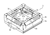
- FIG. It is a perspective view of the 3D data acquisition apparatus of the 3D data acquisition system of the elevator in Embodiment 1.
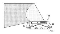
- FIG. It is a side view of the 3D data acquisition apparatus of the 3D data acquisition system of the elevator in Embodiment 1.
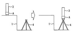
- FIG. It is a figure for demonstrating the method of attaching the 3D data acquisition apparatus of the 3D data acquisition system of an elevator in Embodiment 1 in a sideways state.
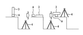
- FIG. 1 It is a figure for demonstrating the method of switching the 3D data acquisition apparatus of the 3D data acquisition system of an elevator in Embodiment 1 from the sideways state to the upward state. It is a figure which shows the measurement result of the floor surface of the hoistway by the 3D data acquisition system of the elevator in Embodiment 1.
- FIG. It is a figure which shows the measurement result of the bottom of the hoistway by the 3D data acquisition system of the elevator in Embodiment 1.
- FIG. It is a figure which shows the measurement result of the hoistway by the 3D data acquisition system of the elevator in Embodiment 1.
- FIG. It is a figure which shows the application screen of the terminal of the 3D data acquisition system of an elevator in Embodiment 1.
- FIG. 1 It is a figure which shows the detection result of the part of the hoistway by the terminal of the 3D data acquisition system of an elevator in Embodiment 1.
- FIG. It is a figure for demonstrating the modification of the measurement method by the 3D data acquisition system of the elevator in Embodiment 1.
- FIG. It is a figure for demonstrating the modification of the measurement method by the 3D data acquisition system of the elevator in Embodiment 1.
- FIG. It is a figure for demonstrating the modification of the measurement method by the 3D data acquisition system of the elevator in Embodiment 1.
- FIG. It is a figure for demonstrating the modification of the measurement method by the 3D data acquisition system of the elevator in Embodiment 1.
- FIG. It is a figure for demonstrating the modification of the measurement method by the 3D data acquisition system of the elevator in Embodiment 1.
- FIG. It is a figure for demonstrating the modification of the measurement method by the 3D data acquisition system of the elevator in Embodiment 1.
- FIG. 1 It is a hardware block diagram of the terminal of the 3D data acquisition system of an elevator in Embodiment 1.
- FIG. It is a top view of the 3D data acquisition apparatus used in the 1st modification of the 3D data acquisition system of an elevator in Embodiment 1.
- FIG. It is a side view of the 3D data acquisition apparatus used in the 1st modification of the 3D data acquisition system of an elevator in Embodiment 1.
- FIG. It is a side view of the 3D data acquisition apparatus used in the 1st modification of the 3D data acquisition system of an elevator in Embodiment 1.
- FIG. It is a side view of the 1st modification of the 3D data acquisition system of an elevator in Embodiment 1.
- FIG. It is a side view of the 1st modification of the 3D data acquisition system of an elevator in Embodiment 1.
- FIG. It is a hardware block diagram of the terminal of the 3D data acquisition system of an elevator in Embodiment 1.
- FIG. It is a top view of
- FIG. 1 It is a side view of the 3D data acquisition apparatus used in the 2nd modification of the 3D data acquisition system of an elevator in Embodiment 1.
- FIG. 2nd modification of the 3D data acquisition system of an elevator in Embodiment 1. It is a side view of the 2nd modification of the 3D data acquisition system of an elevator in Embodiment 1.
- FIG. It is a side view of the 2nd modification of the 3D data acquisition system of an elevator in Embodiment 1.
- FIG. 1 It is a side view of the 3D data acquisition apparatus used in the 2nd modification of the 3D data acquisition system of an elevator in Embodiment 1.
- FIG. 1 is a diagram for explaining an outline of acquisition of three-dimensional data of a hoistway by a three-dimensional data acquisition system of an elevator according to the first embodiment.
- the hoistway 1 penetrates each floor of a building (not shown).
- the car 2 is provided so as to be able to move up and down inside the hoistway 1.
- the three-dimensional data acquisition system includes a three-dimensional data acquisition device 3, a support 4, a rotating body A, a magnet 5, a holding body 6, and a terminal 7.
- the 3D data acquisition device 3 is a device that acquires 3D point cloud data.
- the support 4 is a tripod.
- the rotating body A is provided on the upper part of the support body 4.
- the rotating body A rotatably supports the three-dimensional data acquisition device 3 from below with the rotation axis in the vertical direction.
- the magnet 5 is provided on the support 4.
- the magnet 5 generates a magnetic force.
- the holder 6 is attached to the three-dimensional data acquisition device 3 or the support 4.
- the terminal 7 is a tablet terminal.
- the terminal 7 is detachably held by the holding body 6.
- the first operator when measuring at the bottom of the hoistway 1, the first operator installs the three-dimensional data acquisition system near the center of the bottom of the hoistway 1.
- the holding body 6 is attached to the back surface of the three-dimensional data acquisition device 3.
- the three-dimensional data acquisition device 3 is supported by the rotating body A in a sideways state.
- the first worker starts the measurement of the three-dimensional point cloud data by the three-dimensional data acquisition device 3 by the software of the terminal 7. After that, the three-dimensional data acquisition device 3 automatically rotates 360 degrees. After that, the three-dimensional data acquisition device 3 automatically finishes the measurement of the three-dimensional point cloud data.
- the first worker when measuring on the ceiling of the car 2, the first worker installs the three-dimensional data acquisition system near the center of the ceiling of the car 2. At this time, the holding body 6 is attached to the supporting body 4. The magnet 5 is attracted to the structure on the ceiling of the car 2. The three-dimensional data acquisition device 3 is supported by the rotating body A in an upward state. In this state, the first operator instructs the software of the terminal 7 to start the measurement of the three-dimensional point cloud data by the three-dimensional data acquisition device 3. After that, the first worker evacuates from the ceiling of the car 2. After that, the terminal 7 notifies the start of measurement of the three-dimensional point cloud data by voice and sound. After that, the second worker manually raises and lowers the car 2 inside the car 2. After that, the terminal 7 notifies the end of the measurement of the three-dimensional point cloud data by voice and sound.
- FIG. 2 is a perspective view of a three-dimensional data acquisition device of the three-dimensional data acquisition system of the elevator according to the first embodiment.
- FIG. 3 is a side view of the three-dimensional data acquisition device of the three-dimensional data acquisition system of the elevator according to the first embodiment.
- the three-dimensional data acquisition device 3 includes a first housing 3a, a second housing 3b, a plurality of three-dimensional distance image sensors 3c, and a plurality of light emitting devices 3d.
- the first housing 3a forms a part of the outer shell.
- the first housing 3a is formed in a rectangular shape.
- the second housing 3b is formed separately from the first housing 3a.
- the second housing 3b forms a part of the outer shell.
- the second housing 3b is provided so as to cover the plurality of edges of the first housing 3a on the front side of the first retreat.
- each of the plurality of 3D distance image sensors 3c is a 3D camera.
- the plurality of three-dimensional distance image sensors 3c are provided at the centers of the plurality of edges of the first housing 3a, respectively.
- the measurement directions of the plurality of three-dimensional distance image sensors 3c are set so as to have an elevation angle with respect to the horizontal plane facing each of the plurality of side walls of the hoistway 1 on the horizontal projection surface in the upward state. ..
- the measurement directions of the plurality of three-dimensional distance image sensors 3c are set so as to be the central direction of the first housing 3a.
- the measurement direction of any one of the plurality of three-dimensional distance sensors is such that when in the sideways state, the vertical projection plane faces the floor surface of the hoistway 1 and has an angle with respect to the vertical plane.
- the plurality of three-dimensional distance image sensors 3c acquire three-dimensional point cloud data according to the structure inside the hoistway 1.
- each of the plurality of light emitting devices 3d is an LED.
- the plurality of light emitting devices 3d are provided at positions not within the measurement range of the three-dimensional distance image sensor 3c provided on the side opposite to the side provided on each of the plurality of sides of the second housing 3b.
- the plurality of light emitting devices 3d emit light toward the measurement range of the three-dimensional distance image sensor 3c provided on the side opposite to the side on which the light emitting device 3d is provided.
- FIG. 4 is a diagram for explaining a method of mounting the three-dimensional data acquisition device of the three-dimensional data acquisition system of the elevator according to the first embodiment in a sideways state.
- the three-dimensional data acquisition device 3 is fixed to the rotating body A by a screw (not shown) in the sideways state. Specifically, the three-dimensional data acquisition device 3 is fixed to the rotating body A by rotating the rotating body A in one direction. In this state, the rotating body A is fitted in the upper part of the support 4. As a result, the three-dimensional data acquisition device 3 is maintained in the sideways state.
- FIG. 5 is a diagram for explaining a method of mounting the three-dimensional data acquisition device of the three-dimensional data acquisition system of the elevator according to the first embodiment in an upward state.
- the three-dimensional data acquisition device 3 is fixed to the rotating body A by a screw (not shown) in the upward state. Specifically, the three-dimensional data acquisition device 3 is fixed to the rotating body A by rotating the rotating body A in one direction. In this state, the rotating body A is fitted in the upper part of the support 4. As a result, the three-dimensional data acquisition device 3 is maintained in an upward state.
- FIG. 6 is a diagram for explaining a method of switching the three-dimensional data acquisition device of the three-dimensional data acquisition system of the elevator according to the first embodiment from the sideways state to the upward state.
- the rotating body A is removed from the upper part of the support 4 in a state where the three-dimensional data acquisition device 3 in the sideways state is fixed. After that, the three-dimensional data acquisition device 3 is released from the fixation of the rotating body A by loosening a screw (not shown) in the sideways state. Specifically, the three-dimensional data acquisition device 3 is released from the fixation of the rotating body A by rotating the rotating body A to the other side. After that, the three-dimensional data acquisition device 3 is fixed to the rotating body A by a screw (not shown) in the upward state.
- FIG. 7 is a diagram showing a measurement result of the floor surface of the hoistway by the three-dimensional data acquisition system of the elevator in the first embodiment.
- FIG. 8 is a diagram showing a measurement result of the bottom of the hoistway by the three-dimensional data acquisition system of the elevator in the first embodiment.
- the structure at the bottom of the hoistway 1 is accurately measured.
- the hydraulic plunger 8, the landing door 9 on the lowest floor, and the like are accurately measured.
- FIG. 9 is a diagram showing the measurement results of the hoistway by the three-dimensional data acquisition system of the elevator in the first embodiment.
- the structures other than the bottom of the hoistway 1 are accurately measured.
- the landing door 9 on the middle floor is accurately measured.
- FIG. 10 is a diagram showing an application screen of the terminal of the three-dimensional data acquisition system of the elevator according to the first embodiment.
- FIG. 11 is a diagram showing a detection result of a hoistway portion by the terminal of the three-dimensional data acquisition system of the elevator in the first embodiment.
- the dimension calculation software interactively analyzes the three-dimensional point cloud data inside the hoistway 1 with the operator.
- the dimensional calculation software applies a GUI to calculate the desired dimensions for the interior of the hoistway 1.
- the dimension calculation software has a function specialized in dimension calculation and a function as a viewer of three-dimensional point cloud data.
- the application screen includes a first area and a second area.
- the first area is the area on the left side of the application screen.
- a plurality of tab menus are displayed side by side in the vertical direction.
- the second area is the area on the right side of the application screen.
- the three-dimensional point cloud data acquired by the three-dimensional distance image sensor 3c is displayed.
- the dimension calculation software calculates the average distance between the point cloud corresponding to the side wall surface and floor surface of the hoistway 1 and the reference plane. Specifically, the dimension calculation software uses three planes based on the position of the car side guide rail as reference planes with respect to the lateral dimension of the hoistway 1. The dimension calculation software uses a plane having the same height as the floor of the landing with respect to the vertical dimension as a reference plane.
- Dimension calculation software automatically extracts the reference plane by combining model fitting technology for 3D point cloud data and image processing technology such as 2D pattern matching and straight line extraction.
- the dimensional calculation software automatically extracts the car side guide rail and the landing side sill, which are the standards for the site survey of the elevator, and uses them as the standard for the dimensional calculation of the hoistway 1.
- the dimension calculation software extracts a plane from the three-dimensional point cloud data and performs structural analysis processing such as clustering, and based on the result, the side wall surface and the floor surface of one of the hoistway.
- the three-dimensional point cloud data corresponding to the part of the hoistway 1 such as is automatically extracted.
- the extraction results are displayed in different colors so that they can be distinguished.
- the worker executes the dimension calculation that combines the reference plane, each side wall of the hoistway 1, the floor surface, etc. via the operation of the GUI.
- the worker outputs the acquired dimensions to the outside in a format according to the type of the hoistway 1, the structure of the building, etc. via the terminal 7. For example, the worker registers the dimensional calculation result together with various incidental information in a database or stores it as a document via the terminal 7.
- the terminal 7 includes software or an application for measuring and controlling the three-dimensional distance image sensor and software or an application for calculating dimensions from the measured three-dimensional point cloud data.
- the measurement control software or application includes a three-dimensional point cloud generation function based on SLAM (Simultaneusly Localization and Mapping) or three-dimensional reconstruction technology.
- SLAM Simultaneusly Localization and Mapping
- three-dimensional reconstruction technique for example, the literature "Taguchi, Y., et al .: Point-Plane SLAM for Hand-Held 3D Sensors, IEEE International Conference on Robotics on Robotics and Robotics and The techniques described in are used.
- the plurality of three-dimensional distance image sensors 3c face each of the plurality of side walls of the hoistway 1 on the horizontal projection surface. Therefore, the measurement accuracy of the three-dimensional point cloud data inside the hoistway 1 can be improved.
- the plurality of three-dimensional distance image sensors 3c have an elevation angle with respect to the horizontal plane. Therefore, by increasing the distance to the wall surface of the hoistway 1, the range of imaging the wall surface of the hoistway 1 can be expanded.
- the plurality of three-dimensional distance image sensors 3c are provided in the first housing 3a so that the central direction of the first housing 3a is the measurement direction. Therefore, by increasing the distance to the wall surface of the hoistway 1, the range of imaging the wall surface of the hoistway 1 can be expanded.
- each of the plurality of light emitting devices 3d is provided at a position that does not fall within the measurement range of the corresponding three-dimensional distance image sensor 3c.
- Each of the plurality of light emitting devices 3d emits light toward the measurement range of the corresponding three-dimensional distance image sensor 3c.
- Each of the plurality of light emitting devices 3d emits light so that an obstacle does not enter the irradiation range. Therefore, the three-dimensional point cloud data can be stably acquired.
- the support 4 is provided so that the three-dimensional data acquisition device 3 can support the three-dimensional data acquisition device 3 in the upward state and the sideways state.
- the three-dimensional data acquisition device 3 At the time of measurement at the bottom of the hoistway 1, the three-dimensional data acquisition device 3 is maintained in the sideways state.
- the three-dimensional data acquisition device 3 At the time of measurement on the ceiling of the car 2, the three-dimensional data acquisition device 3 is maintained upward. Therefore, the three-dimensional point cloud data can be easily and accurately acquired at the bottom of the hoistway 1 and the ceiling of the car 2.
- the support 4 rotatably supports the three-dimensional data acquisition device 3 with the rotation axis in the vertical direction. Therefore, the three-dimensional point cloud data can be easily acquired at the bottom of the hoistway 1.
- the magnet 5 is attracted to the structure on the ceiling of the car 2. Therefore, it is possible to prevent the three-dimensional data acquisition system from collapsing on the ceiling of the car 2.
- the terminal 7 receives the three-dimensional point cloud data from the three-dimensional data acquisition device 3. Therefore, the overall three-dimensional point cloud data of the hoistway 1 can be obtained immediately.
- the holding body 6 changes the holding position of the terminal 7 depending on whether the three-dimensional data acquisition device 3 is in the upward state or the sideways state. Therefore, the three-dimensional point cloud data can be easily and accurately acquired at the bottom of the hoistway 1 and the ceiling of the car 2.
- the terminal 7 may notify the information prompting the raising and lowering of the car 2 in accordance with the start of acquisition of the three-dimensional point cloud data by the three-dimensional data acquisition device 3.
- the car 2 can be raised and lowered at an appropriate timing.
- the terminal 7 may perform wireless communication with the three-dimensional data acquisition device 3.
- the terminal 7 may perform wireless communication with the three-dimensional data acquisition device 3.
- a general-purpose three-dimensional camera is adopted. Therefore, the cost of the device can be suppressed.
- the three-dimensional camera is specialized and optimized for the measurement of the hoistway 1 so as to satisfy the specification requirements such as measurement accuracy.
- the dedicated software has a UI that can be operated intuitively. With these systems, it is possible to measure the hoistway 1 and determine whether or not it can be renewed, which is required locally, without any special experience.
- the measured 3D point cloud data is expected to be used in all processes of elevator orders, design, work, installation, and maintenance.
- this embodiment can be used in a wide variety of fields, such as customer proposals, construction setups with construction companies, designs and arrangements that do not require on-site adjustment, and three-dimensional fit judgment in cooperation with BIM. Be expected.
- FIGS. 12 to 15 are diagrams for explaining a modified example of the measurement method by the three-dimensional data acquisition system of the elevator in the first embodiment.
- the three-dimensional data acquisition device 3 is arranged on the ceiling of the car 2 in the sideways state.
- the three-dimensional distance image sensor 3c performs measurement while raising and lowering the car 2.
- the upper three-dimensional distance image sensor 3c measures the upper surface of the structure of the hoistway 1.
- the lower three-dimensional distance image sensor 3c measures the lower surface of the structure of the hoistway 1.
- the three-dimensional data acquisition device 3 measures the upper surface and the lower surface of each of the plurality of brackets 11 that support the car side guide rail 10.
- the three-dimensional data acquisition device 3 measures the upper surface and the lower surface of each of the plurality of landing side thresholds 12.
- the three-dimensional data acquisition device 3 measures the landing door 9 as a whole.
- the distance between adjacent brackets 11 can be accurately measured.
- the floor height can be measured accurately.
- the fall of the landing door 9 it can be determined whether or not the smoke shielding function can be added to the landing door 9.
- FIG. 16 is a hardware configuration diagram of a terminal of the three-dimensional data acquisition system of the elevator according to the first embodiment.
- Each function of the terminal 7 can be realized by a processing circuit.
- the processing circuit includes at least one processor 100a and at least one memory 100b.
- the processing circuit includes at least one dedicated hardware 200.
- each function of the terminal 7 is realized by software, firmware, or a combination of software and firmware. At least one of the software and firmware is written as a program. At least one of the software and firmware is stored in at least one memory 100b. At least one processor 100a realizes each function of the terminal 7 by reading and executing a program stored in at least one memory 100b. At least one processor 100a is also referred to as a central processing unit, a processing unit, an arithmetic unit, a microprocessor, a microcomputer, and a DSP.
- at least one memory 100b is a non-volatile or volatile semiconductor memory such as RAM, ROM, flash memory, EPROM, EEPROM, magnetic disk, flexible disk, optical disk, compact disk, mini disk, DVD, or the like.
- the processing circuit includes at least one dedicated hardware 200
- the processing circuit is realized by, for example, a single circuit, a composite circuit, a programmed processor, a parallel programmed processor, an ASIC, an FPGA, or a combination thereof.
- NS each function of the terminal 7 is realized by a processing circuit.
- each function of the terminal 7 is collectively realized by a processing circuit.
- a part may be realized by the dedicated hardware 200, and the other part may be realized by software or firmware.
- the function of controlling the three-dimensional data acquisition device 3 is realized by a processing circuit as dedicated hardware 200, and at least one processor 100a has at least one function other than the function of controlling the three-dimensional data acquisition device 3. It may be realized by reading and executing a program stored in one memory 100b.
- the processing circuit realizes each function of the terminal 7 by hardware 200, software, firmware, or a combination thereof.
- FIG. 17 is a plan view of the three-dimensional data acquisition device used in the first modification of the three-dimensional data acquisition system of the elevator according to the first embodiment.
- 18 and 19 are side views of the three-dimensional data acquisition device used in the first modification of the three-dimensional data acquisition system of the elevator according to the first embodiment.
- FIG. 20 is a side view of a first modification of the three-dimensional data acquisition system of the elevator according to the first embodiment.
- the plurality of three-dimensional distance image sensors 3c are provided in the first housing 3a without having an elevation angle with respect to the horizontal plane.
- the plurality of three-dimensional distance image sensors 3c are provided in the first housing 3a so that the direction opposite to the central direction of the first housing 3a is the measurement direction.
- the plurality of light emitting devices 3d are provided at positions not within the respective measurement ranges of the three-dimensional distance image sensor 3c at the plurality of edges of the second housing 3b.
- the plurality of light emitting devices 3d emit light toward the respective measurement ranges of the plurality of three-dimensional distance image sensors 3c.
- the plurality of light emitting devices 3d emit light so that obstacles do not enter the irradiation range.
- the support portion 4a of the support body 4 is provided so as to project horizontally from the upper surface of the rotating body A.
- the support portion 4a supports the three-dimensional data acquisition device 3 in a sideways state while being attached to the side opposite to the plurality of three-dimensional distance image sensors 3c in the first housing 3a.
- 21 and 22 are side views of the three-dimensional data acquisition device used in the second modification of the three-dimensional data acquisition system of the elevator according to the first embodiment.
- 23 and 24 are side views of a second modification of the three-dimensional data acquisition system for the elevator according to the first embodiment.
- the plurality of three-dimensional distance image sensors 3c are provided in the first housing 3a with an elevation angle with respect to the horizontal plane.
- the plurality of three-dimensional distance image sensors 3c are provided in the first housing 3a so that the direction opposite to the central direction of the first housing 3a is the measurement direction.
- the plurality of light emitting devices 3d are provided at positions not within the respective measurement ranges of the three-dimensional distance image sensor 3c at the plurality of edges of the second housing 3b.
- the plurality of light emitting devices 3d emit light toward the respective measurement ranges of the plurality of three-dimensional distance image sensors 3c.
- the plurality of light emitting devices 3d emit light so that obstacles do not enter the irradiation range.
- the support 4 supports the three-dimensional data acquisition device 3 in the sideways state from below.
- the support portion 4a of the support body 4 is provided so as to project horizontally from the upper surface of the rotating body A.
- the support portion 4a supports the three-dimensional data acquisition device 3 in a sideways state while being attached to the side opposite to the plurality of three-dimensional distance image sensors 3c in the first housing 3a.
- the three-dimensional data acquisition device, the three-dimensional data acquisition system, and the three-dimensional data acquisition method of the elevator of the present disclosure can be used for the elevator system.
Landscapes
- Engineering & Computer Science (AREA)
- Automation & Control Theory (AREA)
- Computer Networks & Wireless Communication (AREA)
- Multimedia (AREA)
- Signal Processing (AREA)
- Civil Engineering (AREA)
- Mechanical Engineering (AREA)
- Structural Engineering (AREA)
- Length Measuring Devices By Optical Means (AREA)
- Lift-Guide Devices, And Elevator Ropes And Cables (AREA)
- Indicating And Signalling Devices For Elevators (AREA)
Abstract
昇降路の内部の3次元点群データの計測精度を向上することができるエレベーターの3次元データ取得装置、3次元データ取得システムおよび3次元データ取得方法を提供する。エレベーターの3次元データ取得装置は、外郭をなす筐体と、水平投影面上においてエレベーターの昇降路の複数の側壁のそれぞれに対して正対して前記筐体に設けられ、3次元点群データを取得する複数の3次元距離画像センサと、を備えた。当該構成によれば、昇降路の内部の3次元点群データの計測精度を向上することができる。
Description
本開示は、エレベーターの3次元データ取得装置、3次元データ取得システムおよび3次元データ取得方法に関する。
特許文献1は、エレベーターの3次元データ取得装置を開示する。当該3次元データ取得装置によれば、昇降路の内部の3次元点群データを計測することができる。
しかしながら、特許文献1に記載の3次元データ取得装置においては、水平投影面上において昇降路の壁に対して計測方向が必ずしも正対しない。このため、3次元点群データの計測精度が下がり得る。
本開示は、上述の課題を解決するためになされた。本開示の目的は、昇降路の内部の3次元点群データの計測精度を向上することができるエレベーターの3次元データ取得装置、3次元データ取得システムおよび3次元データ取得方法を提供することである。
本開示に係るエレベーターの3次元データ取得装置は、外郭をなす筐体と、水平投影面上においてエレベーターの昇降路の複数の側壁のそれぞれに対して正対して前記筐体に設けられ、3次元点群データを取得する複数の3次元距離画像センサと、を備えた。
本開示に係るエレベーターの3次元データ取得システムは、前記3次元データ取得装置と、前記複数の3次元距離画像センサの計測方向が水平投影面上においてエレベーターの昇降路の複数の側壁のそれぞれに対して正対した状態を上向き状態とし、前記複数の3次元距離画像センサのうちのひとつの計測方向が鉛直投影面上において前記昇降路の床面に対して正対した状態を横向き状態とし、前記上向き状態と前記横向き状態とで前記3次元データ取得装置を支持し得るように設けられた支持体、を備えた。
本開示に係るエレベーターの3次元データ取得方法は、前記かごの天井において前記3次元データ取得システムの前記筐体を前記上向き状態で設置する第1設置工程と、前記第1支持工程の後、前記端末が前記かごの昇降を促す情報を報知した際に前記かごを昇降させる昇降工程と、を備えた。
本開示によれば、複数の3次元距離画像センサは、水平投影面上においてエレベーターの昇降路の複数の側壁のそれぞれに対して正対して水平面に対して上方向の角度を持って前記筐体の中央の方向が計測方向となるように筐体に設けられる。このため、昇降路の内部の3次元点群データの計測精度を向上することができる。
実施の形態について添付の図面に従って説明する。なお、各図中、同一または相当する部分には同一の符号が付される。当該部分の重複説明は適宜に簡略化ないし省略する。
実施の形態1.
図1は実施の形態1におけるエレベーターの3次元データ取得システムによる昇降路の3次元データの取得の概要を説明するための図である。
図1は実施の形態1におけるエレベーターの3次元データ取得システムによる昇降路の3次元データの取得の概要を説明するための図である。
図1のエレベーターシステムにおいて、昇降路1は、図示されない建築物の各階を貫く。かご2は、昇降路1の内部を昇降し得るように設けられる。
3次元データ取得システムは、3次元データ取得装置3と支持体4と回転体Aと磁石5と保持体6と端末7とを備える。
3次元データ取得装置3は、3次元点群データを取得する装置である。例えば、支持体4は、三脚である。回転体Aは、支持体4の上部に設けられる。回転体Aは、回転軸を鉛直方向として3次元データ取得装置3を回転自在に下方から支持する。磁石5は、支持体4に設けられる。磁石5は、磁力を発生させる。保持体6は、3次元データ取得装置3または支持体4に取り付けられる。例えば、端末7は、タブレット端末である。端末7は、保持体6に着脱自在に保持される。
図1の左側に示されるように、昇降路1の底部での計測時において、第1作業者は、3次元データ取得システムを昇降路1の底部の中央付近に設置する。この際、保持体6は、3次元データ取得装置3の裏面に取り付けられる。3次元データ取得装置3は、横向き状態で回転体Aに支持される。この状態において、第1作業者は、端末7のソフトウェアにより3次元データ取得装置3による3次元点群データの計測を開始させる。その後、3次元データ取得装置3は、自動で360度回転する。その後、3次元データ取得装置3は、自動で3次元点群データの計測を終了する。
図1の右側に示されるように、かご2の天井での計測時において、第1作業者は、3次元データ取得システムをかご2の天井の中央付近に設置する。この際、保持体6は、支持体4に取り付けられる。磁石5は、かご2の天井の構造物に吸着する。3次元データ取得装置3は、上向き状態で回転体Aに支持される。この状態において、第1作業者は、端末7のソフトウェアにより3次元データ取得装置3による3次元点群データの計測の開始を指示する。その後、第1作業者は、かご2の天井から退避する。その後、端末7は、3次元点群データの計測の開始を音声と音とで報知する。その後、第2作業者は、かご2の内部においてかご2を手動運転で昇降させる。その後、端末7は、3次元点群データの計測の終了を音声と音とで報知する。
次に、図2と図3とを用いて、3次元データ取得装置3を説明する。
図2は実施の形態1におけるエレベーターの3次元データ取得システムの3次元データ取得装置の斜視図である。図3は実施の形態1におけるエレベーターの3次元データ取得システムの3次元データ取得装置の側面図である。
図2は実施の形態1におけるエレベーターの3次元データ取得システムの3次元データ取得装置の斜視図である。図3は実施の形態1におけるエレベーターの3次元データ取得システムの3次元データ取得装置の側面図である。
図2と図3とに示されるように、3次元データ取得装置3は、第1筐体3aと第2筐体3bと複数の3次元距離画像センサ3cと複数の発光装置3dとを備える。
第1筐体3aは、外郭の一部をなす。例えば、第1筐体3aは、矩形状に形成される。第2筐体3bは、第1筐体3aとは別に形成される。第2筐体3bは、外郭の一部をなす。第2筐体3bは、第1後退の表側において前記第1筐体3aの複数の縁部を覆うように設けられる。
例えば、複数の3次元距離画像センサ3cの各々は、3次元カメラである。複数の3次元距離画像センサ3cは、第1筐体3aの複数の縁部の中央にそれぞれ設けられる。複数の3次元距離画像センサ3cの計測方向は、上向き状態の際に水平投影面上において昇降路1の複数の側壁のそれぞれに対して正対して水平面に対して仰角を持つように設定される。複数の3次元距離画像センサ3c計測方向は、第1筐体3aの中央の方向となるように設定される。複数の第3次元距離センサのうちのいずれかひとつの計測方向は、横向き状態の際に鉛直投影面上において昇降路1の床面に対して正対して鉛直面に対して角度を持つように設定される。複数の3次元距離画像センサ3cは、昇降路1の内部の構造物に応じた3次元点群データを取得する。
例えば、複数の発光装置3dの各々は、LEDである。複数の発光装置3dは、第2筐体3bの複数の辺にそれぞれにおいて自らが設けられた側とは反対側に設けられた3次元距離画像センサ3cの計測範囲に入らない位置に設けられる。複数の発光装置3dは、自らが設けられた側とは反対側に設けられた3次元距離画像センサ3cの計測範囲に向けて光を発する。
次に、図4を用いて、3次元データ取得装置3を横向き状態で取り付ける方法を説明する。
図4は実施の形態1におけるエレベーターの3次元データ取得システムの3次元データ取得装置を横向き状態で取り付ける方法を説明するための図である。
図4は実施の形態1におけるエレベーターの3次元データ取得システムの3次元データ取得装置を横向き状態で取り付ける方法を説明するための図である。
図4において、3次元データ取得装置3は、横向き状態において図示されないネジにより回転体Aに固定される。具体的には、3次元データ取得装置3は、回転体Aを一方向に回転させることで回転体Aに固定される。この状態において、回転体Aは、支持体4の上部にはめ込まれる。その結果、3次元データ取得装置3は、横向き状態に維持される。
次に、図5を用いて、3次元データ取得装置3を上向き状態で取り付ける方法を説明する。
図5は実施の形態1におけるエレベーターの3次元データ取得システムの3次元データ取得装置を上向き状態で取り付ける方法を説明するための図である。
図5は実施の形態1におけるエレベーターの3次元データ取得システムの3次元データ取得装置を上向き状態で取り付ける方法を説明するための図である。
図5において、3次元データ取得装置3は、上向き状態において図示されないネジにより回転体Aに固定される。具体的には、3次元データ取得装置3は、回転体Aを一方向に回転させることで回転体Aに固定される。この状態において、回転体Aは、支持体4の上部にはめ込まれる。その結果、3次元データ取得装置3は、上向き状態に維持される。
次に、図6を用いて、3次元データ取得装置3を横向き状態から上向き状態に切り換える方法を説明する。
図6は実施の形態1におけるエレベーターの3次元データ取得システムの3次元データ取得装置を横向き状態から上向き状態に切り換える方法を説明するための図である。
図6は実施の形態1におけるエレベーターの3次元データ取得システムの3次元データ取得装置を横向き状態から上向き状態に切り換える方法を説明するための図である。
図6において、回転体Aは、横向き状態の3次元データ取得装置3が固定された状態で支持体4の上部から取り外される。その後、3次元データ取得装置3は、横向き状態において図示されないネジを緩めることにより回転体Aの固定から解放される。具体的には、3次元データ取得装置3は、回転体Aを他方に回転させることで回転体Aの固定から解放される。その後、3次元データ取得装置3は、上向き状態において図示されないネジにより回転体Aに固定される。
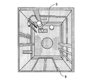
次に、図7と図8とを用いて、3次元データ取得装置3を横向きにして昇降路1の底部を計測した際の結果を模式的に説明する。
図7は実施の形態1におけるエレベーターの3次元データ取得システムによる昇降路の床面の計測結果を示す図である。図8は実施の形態1におけるエレベーターの3次元データ取得システムによる昇降路の底部の計測結果を示す図である。
図7は実施の形態1におけるエレベーターの3次元データ取得システムによる昇降路の床面の計測結果を示す図である。図8は実施の形態1におけるエレベーターの3次元データ取得システムによる昇降路の底部の計測結果を示す図である。
図7と図8とに示されるように、昇降路1の底部の構造物は、正確に計測される。例えば、油圧プランジャー8、最下階の乗場ドア9等が正確に計測される。
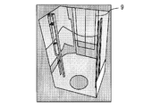
次に、図9を用いて、3次元データ取得装置3を上向きにして昇降路1を計測した際の結果を模式的に説明する。
図9は実施の形態1におけるエレベーターの3次元データ取得システムによる昇降路の計測結果を示す図である。
図9は実施の形態1におけるエレベーターの3次元データ取得システムによる昇降路の計測結果を示す図である。
図9に示されるように、昇降路1の底部以外の構造物は、正確に計測される。例えば、中間階の乗場ドア9等が正確に計測される。
次に、図10と図11とを用いて、端末7を説明する。
図10は実施の形態1におけるエレベーターの3次元データ取得システムの端末のアプリケーション画面を示す図である。図11は実施の形態1におけるエレベーターの3次元データ取得システムの端末による昇降路の部位の検出結果を示す図である。
図10は実施の形態1におけるエレベーターの3次元データ取得システムの端末のアプリケーション画面を示す図である。図11は実施の形態1におけるエレベーターの3次元データ取得システムの端末による昇降路の部位の検出結果を示す図である。
端末7において、寸法計算ソフトウェアは、昇降路1の内部の3次元点群データに対して作業者とインタラクティブに解析を行う。寸法計算ソフトウェアは、昇降路1の内部に対して所望の寸法を計算するためのGUIを適用する。寸法計算ソフトウェアは、寸法計算に特化した機能の他、3次元点群データのビューワとしての機能を備える。
図10に示されるように、アプリケーション画面は、第1領域と第2領域とを備える。第1領域は、アプリケーション画面の左側の領域である。第1領域においては、複数のタブメニューが鉛直方向に並んで表示される。第2領域は、アプリケーション画面の右側の領域である。第2領域においては、3次元距離画像センサ3cが取得した3次元点群データを表示する。
寸法計算ソフトウェアは、昇降路1の側壁面、床面といった部位に相当する点群と基準平面との距離の平均を計算する。具体的には、寸法計算ソフトウェアは、昇降路1の横方向の寸法に関してかご側ガイドレールの位置に基づく3つの平面を基準平面とする。寸法計算ソフトウェアは、縦方向の寸法に関して乗場の床面と同じ高さを持った平面を基準平面とする。
寸法計算ソフトウェアは、3次元点群データに対するモデルフィッティング技術、2次元パターンマッチング、直線抽出等の画像処理技術を組み合わせて基準平面を自動で抽出する。例えば,寸法計算ソフトウェアは、エレベーターの現場調査の基準となるかご側ガイドレール,乗場側敷居を自動で抽出することで昇降路1の寸法計算の基準とする。
図11に示されるように、寸法計算ソフトウェアは、3次元点群データに対して平面を抽出したりクラスタリングといった構造解析処理を行ったりした結果に基づいて、昇降路の1の側壁面、床面といった昇降路1の部位に相当する3次元点群データを自動で抽出する。抽出結果は、色を変えて区別がつくように表示される。
作業者は、寸法計算ソフトウェアの機能により得られた結果に基づいて、GUIの操作を介して、基準平面と昇降路1の各側壁、床面等を組み合わせた寸法計算を実行する。
作業者は、端末7を介して、昇降路1の種別、建物の構造等に応じたフォーマットで、取得した寸法を外部に出力する。例えば、作業者は、端末7を介して、寸法計算結果を各種付随情報とともにデータベースに登録したりドキュメントとして保管したりする。
なお、端末7は、3次元距離画像センサの計測制御を行うソフトウェアまたはアプリケーションと計測された3次元点群データから寸法計算を行うソフトウェアまたはアプリケーションを備える。計測制御のソフトウェアまたはアプリケーションは、SLAM(Simultaneously Localization and Mapping)または3次元再構成技術に基づく3次元点群生成機能を備える。3次元再構成技術としては、例えば、文献「Taguchi, Y., et al.:Point-Plane SLAM for Hand-Held 3D Sensors, IEEE International Conference on Robotics and Automation (ICRA), 5182-5189 (2013)」に記載された技術が用いられる。
以上で説明した実施の形態1によれば、複数の3次元距離画像センサ3cは、水平投影面上において昇降路1の複数の側壁のそれぞれに対して正対する。このため、昇降路1の内部の3次元点群データの計測精度を向上することができる。
また、複数の3次元距離画像センサ3cは、水平面に対して仰角を持つ。このため、昇降路1の壁面に対する距離を稼ぐことで、昇降路1の壁面を撮像する範囲を広げることができる。
また、複数の3次元距離画像センサ3cは、第1筐体3aの中央の方向が計測方向となるように第1筐体3aに設けられる。このため、昇降路1の壁面に対する距離を稼ぐことで、昇降路1の壁面を撮像する範囲を広げることができる。
また、複数の発光装置3dの各々は、対応した3次元距離画像センサ3cの計測範囲に入らない位置に設けられる。複数の発光装置3dの各々は、対応した3次元距離画像センサ3cの計測範囲に向けて光を発する。複数の発光装置3dの各々は、障害物が照射範囲に入らないように光を発する。このため、3次元点群データを安定して取得することができる。
また、支持体4は、3次元データ取得装置3を上向き状態と横向き状態とで3次元データ取得装置3を支持し得るように設けられる。昇降路1の底部での計測時において、3次元データ取得装置3は、横向き状態に維持される。かご2の天井での計測時において、3次元データ取得装置3は、上向きに維持される。このため、昇降路1の底部およびかご2の天井で3次元点群データを容易かつ正確に取得することができる。
また、支持体4は、回転軸を鉛直方向として3次元データ取得装置3を回転自在に支持する。このため、昇降路1の底部で3次元点群データを容易に取得することができる。
また、磁石5は、かご2の天井の構造物に吸着する。このため、かご2の天井において、3次元データ取得システムが倒れることを抑制できる。
また、端末7は、3次元データ取得装置3から3次元点群データを受信する。このため、昇降路1の全体的な3次元点群データを早急に得ることができる。
また、保持体6は、3次元データ取得装置3が上向き状態のときと横向き状態のときとで端末7の保持位置を変える。このため、昇降路1の底部およびかご2の天井で3次元点群データを容易かつ正確に取得することができる。
また、端末7において、3次元データ取得装置3による3次元点群データの取得の開始に合わせてかご2の昇降を促す情報を報知してもよい。この場合、適切なタイミングでかご2を昇降させることができる。
なお、端末7は、3次元データ取得装置3と無線通信を行ってもよい。この場合、かご2の天井に3次元データ取得装置3を設置した後、かご2の内部から端末7を操作することで、昇降路1の3次元点群データを安全に取得することができる。
本実施の形態においては、汎用の3次元カメラが採用される。このため、機器のコストを抑制することができる。この際、3次元カメラは、計測精度等の仕様要求を満たせるよう昇降路1の計測に特化および最適化される。
また、専用のソフトウェアは、直感的に操作できるUIとなっている。これらのシステムにより、現地で求められる昇降路1の計測およびリニューアル対応可否の判断が特殊な経験がなくても行える。
計測された3次元点群データは、エレベーターの受注、設計、工作、据付、保守の全工程での活用が期待される。
本実施の形態によれば、客先提案、建築事業者との工事の段取り、現地合わせの必要のない設計と手配、BIMと協調した3次元の納まり判定等、多種多様な方面への活用が期待される。
次に、図12から図15を用いて、3次元データ取得システムによる計測方法の変形例を説明する。
図12から図15は実施の形態1におけるエレベーターの3次元データ取得システムによる計測方法の変形例を説明するための図である。
図12から図15は実施の形態1におけるエレベーターの3次元データ取得システムによる計測方法の変形例を説明するための図である。
図12においては、3次元データ取得装置3は、横向き状態においてかご2の天井に配置される。この状態において、かご2を昇降させながら、3次元距離画像センサ3cは、計測を行う。この場合、上側の3次元距離画像センサ3cは、昇降路1の構造物の上面を計測する。下側の3次元距離画像センサ3cは、昇降路1の構造物の下面を計測する。
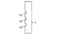
例えば、図13に示されるように、3次元データ取得装置3は、かご側ガイドレール10を支持する複数のブラケット11の各々における上面と下面とを計測する。例えば、図14に示されるように、3次元データ取得装置3は、複数の乗場側敷居12の各々における上面と下面とを計測する。例えば、図15に示されるように、3次元データ取得装置3は、乗場ドア9を全体的に計測する。
当該変形例によれば、隣接したブラケット11の間隔を正確に計測することができる。隣接した乗場側敷居12の縁部を計測することで、階高を正確に計測することができる。乗場ドア9の倒れを計測することで、遮煙機能を乗場ドア9に追加できるか否かを判定することができる。
次に、図16を用いて、端末7の例を説明する。
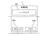
図16は実施の形態1におけるエレベーターの3次元データ取得システムの端末のハードウェア構成図である。
図16は実施の形態1におけるエレベーターの3次元データ取得システムの端末のハードウェア構成図である。
端末7の各機能は、処理回路により実現し得る。例えば、処理回路は、少なくとも1つのプロセッサ100aと少なくとも1つのメモリ100bとを備える。例えば、処理回路は、少なくとも1つの専用のハードウェア200を備える。
処理回路が少なくとも1つのプロセッサ100aと少なくとも1つのメモリ100bとを備える場合、端末7の各機能は、ソフトウェア、ファームウェア、またはソフトウェアとファームウェアとの組み合わせで実現される。ソフトウェアおよびファームウェアの少なくとも一方は、プログラムとして記述される。ソフトウェアおよびファームウェアの少なくとも一方は、少なくとも1つのメモリ100bに格納される。少なくとも1つのプロセッサ100aは、少なくとも1つのメモリ100bに記憶されたプログラムを読み出して実行することにより、端末7の各機能を実現する。少なくとも1つのプロセッサ100aは、中央処理装置、処理装置、演算装置、マイクロプロセッサ、マイクロコンピュータ、DSPともいう。例えば、少なくとも1つのメモリ100bは、RAM、ROM、フラッシュメモリ、EPROM、EEPROM等の、不揮発性または揮発性の半導体メモリ、磁気ディスク、フレキシブルディスク、光ディスク、コンパクトディスク、ミニディスク、DVD等である。
処理回路が少なくとも1つの専用のハードウェア200を備える場合、処理回路は、例えば、単一回路、複合回路、プログラム化したプロセッサ、並列プログラム化したプロセッサ、ASIC、FPGA、またはこれらの組み合わせで実現される。例えば、端末7の各機能は、それぞれ処理回路で実現される。例えば、端末7の各機能は、まとめて処理回路で実現される。
端末7の各機能について、一部を専用のハードウェア200で実現し、他部をソフトウェアまたはファームウェアで実現してもよい。例えば、3次元データ取得装置3を制御する機能については専用のハードウェア200としての処理回路で実現し、3次元データ取得装置3を制御する機能以外の機能については少なくとも1つのプロセッサ100aが少なくとも1つのメモリ100bに格納されたプログラムを読み出して実行することにより実現してもよい。
このように、処理回路は、ハードウェア200、ソフトウェア、ファームウェア、またはこれらの組み合わせで端末7の各機能を実現する。
次に、図17から図20を用いて、3次元データ取得システムの第1変形例を説明する。
図17は実施の形態1におけるエレベーターの3次元データ取得システムの第1変形例に用いられる3次元データ取得装置の平面図である。図18と図19とは実施の形態1におけるエレベーターの3次元データ取得システムの第1変形例に用いられる3次元データ取得装置の側面図である。図20は実施の形態1におけるエレベーターの3次元データ取得システムの第1変形例の側面図である。
図17は実施の形態1におけるエレベーターの3次元データ取得システムの第1変形例に用いられる3次元データ取得装置の平面図である。図18と図19とは実施の形態1におけるエレベーターの3次元データ取得システムの第1変形例に用いられる3次元データ取得装置の側面図である。図20は実施の形態1におけるエレベーターの3次元データ取得システムの第1変形例の側面図である。
図17と図18とに示されるように、3次元データ取得装置3において、複数の3次元距離画像センサ3cは、水平面に対して仰角を持たずに第1筐体3aに設けられる。複数の3次元距離画像センサ3cは、第1筐体3aの中央の方向とは反対方向が計測方向となるように第1筐体3aに設けられる。
図19に示されるように、複数の発光装置3dは、第2筐体3bの複数の縁部において3次元距離画像センサ3cのそれぞれの計測範囲に入らない位置にそれぞれ設けられる。複数の発光装置3dは、複数の3次元距離画像センサ3cのそれぞれの計測範囲に向けて光を発する。複数の発光装置3dは、障害物が照射範囲に入らないように光を発する。
図20に示されるように、支持体4の支持部4aは、回転体Aの上面から水平方向に突き出すように設けられる。当該支持部4aは、第1筐体3aにおいて複数の3次元距離画像センサ3cとは反対側に取り付けられた状態で横向き状態の3次元データ取得装置3を支持する。
次に、図21から図24を用いて、3次元データ取得システムの第2変形例を説明する。
図21と図22とは実施の形態1におけるエレベーターの3次元データ取得システムの第2変形例に用いられる3次元データ取得装置の側面図である。図23と図24とは実施の形態1におけるエレベーターの3次元データ取得システムの第2変形例の側面図である。
図21と図22とは実施の形態1におけるエレベーターの3次元データ取得システムの第2変形例に用いられる3次元データ取得装置の側面図である。図23と図24とは実施の形態1におけるエレベーターの3次元データ取得システムの第2変形例の側面図である。
図21に示されるように、3次元データ取得装置3において、複数の3次元距離画像センサ3cは、水平面に対して仰角を持って第1筐体3aに設けられる。複数の3次元距離画像センサ3cは、第1筐体3aの中央の方向とは反対方向が計測方向となるように第1筐体3aに設けられる。
図22に示されるように、複数の発光装置3dは、第2筐体3bの複数の縁部において3次元距離画像センサ3cのそれぞれの計測範囲に入らない位置にそれぞれ設けられる。複数の発光装置3dは、複数の3次元距離画像センサ3cのそれぞれの計測範囲に向けて光を発する。複数の発光装置3dは、障害物が照射範囲に入らないように光を発する。
例えば、図23に示されるように、支持体4は、横向き状態の3次元データ取得装置3を下方から支持する。
例えば、図24に示されるように、支持体4の支持部4aは、回転体Aの上面から水平方向に突き出すように設けられる。当該支持部4aは、第1筐体3aにおいて複数の3次元距離画像センサ3cとは反対側に取り付けられた状態で横向き状態の3次元データ取得装置3を支持する。
以上のように、本開示のエレベーターの3次元データ取得装置、3次元データ取得システムおよび3次元データ取得方法は、エレベーターシステムに利用できる。
1 昇降路、 2 かご、 3 3次元データ取得装置、 3a 第1筐体、 3b 第2筐体、 3c 3次元距離画像センサ、 3d 発光装置、 4 支持体、 4a 支持部、 5 磁石、 6 保持体、 7 端末、 8 油圧プランジャー、 9 乗場ドア、 10 かご側ガイドレール、 11 ブラケット、 12 乗場側敷居、 100a プロセッサ、 100b メモリ、 200 ハードウェア
Claims (13)
- 外郭をなす筐体と、
水平投影面上においてエレベーターの昇降路の複数の側壁のそれぞれに対して正対して前記筐体に設けられ、3次元点群データを取得する複数の3次元距離画像センサと、
を備えたエレベーターの3次元データ取得装置。 - 前記複数の3次元距離画像センサは、水平面に対して仰角を持って前記筐体に設けられた請求項1に記載のエレベーターの3次元データ取得装置。
- 前記複数の3次元距離画像センサは、前記筐体の中央の方向が計測方向となるように前記筐体に設けられた請求項2に記載のエレベーターの3次元データ取得装置。
- 前記筐体は、水平投影面上において矩形状に形成され、
前記複数の3次元距離画像センサは、前記筐体の複数の縁部にそれぞれ設けられた請求項1から請求項3のいずれか一項に記載のエレベーターの3次元データ取得装置。 - 前記筐体の複数の縁部において前記複数の3次元距離画像センサのそれぞれの計測範囲に入らない位置にそれぞれ設けられ、前記複数の3次元距離画像センサのそれぞれの計測範囲に向け、障害物が照射範囲に入らないように光を発する複数の発光装置、
を備えた請求項1から請求項4のいずれか一項に記載のエレベーターの3次元データ取得装置。 - 請求項1から請求項5のいずれか一項に記載の3次元データ取得装置と、
前記複数の3次元距離画像センサの計測方向が水平投影面上においてエレベーターの昇降路の複数の側壁のそれぞれに対して正対した状態を上向き状態とし、前記複数の3次元距離画像センサのうちのひとつの計測方向が鉛直投影面上において前記昇降路の床面に対して正対した状態を横向き状態とし、前記上向き状態と前記横向き状態とで前記3次元データ取得装置を支持し得るように設けられた支持体、
を備えたエレベーターの3次元データ取得システム。 - 前記支持体は、回転軸を鉛直方向として前記3次元データ取得装置を回転自在に支持する請求項6に記載のエレベーターの3次元データ取得システム。
- 前記支持体に設けられ、磁力を発生させる磁石、
を備えた請求項6または請求項7に記載のエレベーターの3次元データ取得システム。 - 前記3次元データ取得装置から3次元点群データを受信する端末、
を備えた請求項6から請求項8のいずれか一項に記載のエレベーターの3次元データ取得システム。 - 前記支持体が前記上向き状態で前記筐体を支持する際に前記支持体に取り付けられ、前記支持体が前記横向き状態で前記筐体を支持する際に前記筐体において前記複数の3次元距離画像センサの側とは反対側に取り付けられ、前記端末を保持する保持体、
を備えた請求項9に記載のエレベーターの3次元データ取得システム。 - 前記端末は、前記3次元データ取得装置による3次元点群データの取得の開始に合わせて前記エレベーターのかごの昇降を促す情報を報知する請求項9または請求項10に記載のエレベーターの3次元データ取得システム。
- 前記かごの天井において請求項11に記載の3次元データ取得システムの前記筐体を前記上向き状態で設置する第1設置工程と、
前記第1設置工程の後、前記端末が前記かごの昇降を促す情報を報知した際に前記かごを昇降させる昇降工程と、
を備えたエレベーターの3次元データ取得方法。 - 前記昇降路の底部において前記筐体を前記横向き状態で設置する第2設置工程と、
前記第2設置工程の後、鉛直方向を回転軸として前記筐体を回転させながら前記複数の3次元距離画像センサに3次元点群データを取得させるデータ取得工程と、
を備えた請求項12に記載のエレベーターの3次元データ取得方法。
Priority Applications (5)
| Application Number | Priority Date | Filing Date | Title |
|---|---|---|---|
| PCT/JP2020/017982 WO2021220344A1 (ja) | 2020-04-27 | 2020-04-27 | エレベーターの3次元データ取得装置、3次元データ取得システムおよび3次元データ取得方法 |
| US17/920,063 US20230159301A1 (en) | 2020-04-27 | 2020-04-27 | 3d data acquisition device, 3d data acquisition system, and 3d data acquisition method for elevator |
| CN202080100022.9A CN115485224A (zh) | 2020-04-27 | 2020-04-27 | 电梯的三维数据取得装置、三维数据取得系统以及三维数据取得方法 |
| DE112020007118.9T DE112020007118T5 (de) | 2020-04-27 | 2020-04-27 | 3D-Datenerfassungsvorrichtung, 3D-Datenerfassungssystem und 3D-Datenerfassungsverfahren für einen Aufzug |
| JP2022518442A JP7347663B2 (ja) | 2020-04-27 | 2020-04-27 | エレベーターの3次元データ取得装置、3次元データ取得システムおよび3次元データ取得方法 |
Applications Claiming Priority (1)
| Application Number | Priority Date | Filing Date | Title |
|---|---|---|---|
| PCT/JP2020/017982 WO2021220344A1 (ja) | 2020-04-27 | 2020-04-27 | エレベーターの3次元データ取得装置、3次元データ取得システムおよび3次元データ取得方法 |
Publications (1)
| Publication Number | Publication Date |
|---|---|
| WO2021220344A1 true WO2021220344A1 (ja) | 2021-11-04 |
Family
ID=78373424
Family Applications (1)
| Application Number | Title | Priority Date | Filing Date |
|---|---|---|---|
| PCT/JP2020/017982 Ceased WO2021220344A1 (ja) | 2020-04-27 | 2020-04-27 | エレベーターの3次元データ取得装置、3次元データ取得システムおよび3次元データ取得方法 |
Country Status (5)
| Country | Link |
|---|---|
| US (1) | US20230159301A1 (ja) |
| JP (1) | JP7347663B2 (ja) |
| CN (1) | CN115485224A (ja) |
| DE (1) | DE112020007118T5 (ja) |
| WO (1) | WO2021220344A1 (ja) |
Cited By (1)
| Publication number | Priority date | Publication date | Assignee | Title |
|---|---|---|---|---|
| JP7301945B1 (ja) | 2021-12-15 | 2023-07-03 | 東芝エレベータ株式会社 | 昇降路内座標軸設定方法及び昇降路形状計測装置 |
Families Citing this family (1)
| Publication number | Priority date | Publication date | Assignee | Title |
|---|---|---|---|---|
| KR102776633B1 (ko) | 2024-10-10 | 2025-03-06 | 아이이앤엘 주식회사 | 3d 데이터 기반 엘리베이터 설치 단계 별 검수 방법 및 이를 수행하는 전자 장치 |
Citations (5)
| Publication number | Priority date | Publication date | Assignee | Title |
|---|---|---|---|---|
| JP2005096919A (ja) * | 2003-09-24 | 2005-04-14 | Toshiba Elevator Co Ltd | エレベータの寸法測定装置及びエレベータの寸法測定方法 |
| WO2016199850A1 (ja) * | 2015-06-09 | 2016-12-15 | 三菱電機株式会社 | 昇降路寸法計測装置および昇降路寸法計測方法 |
| JP2017193327A (ja) * | 2016-04-19 | 2017-10-26 | 富士通株式会社 | 飛翔機、飛翔機の使用方法、飛翔機のフレーム |
| JP2018173392A (ja) * | 2017-03-31 | 2018-11-08 | 株式会社日立ビルシステム | データ統合装置及び方法並びにプログラム |
| JP2020040781A (ja) * | 2018-09-10 | 2020-03-19 | 株式会社日立ビルシステム | 計測システム、及び、計測方法 |
Family Cites Families (7)
| Publication number | Priority date | Publication date | Assignee | Title |
|---|---|---|---|---|
| JP3715588B2 (ja) * | 2002-06-03 | 2005-11-09 | アジア航測株式会社 | 構造物の壁面調査装置 |
| FI119983B (fi) * | 2006-05-24 | 2009-05-29 | Kone Corp | Menetelmä ja järjestelmä hissin johteiden asentamiseksi |
| JP6693255B2 (ja) * | 2016-04-28 | 2020-05-13 | 富士通株式会社 | 計測機器及び計測システム |
| EP3424858B1 (en) * | 2017-07-03 | 2020-04-01 | Otis Elevator Company | Elevator maintenance space projection systems |
| CN107561085B (zh) * | 2017-08-28 | 2018-12-18 | 武汉大学 | 一种大型水电站百米级引水竖井健康检测装备及方法 |
| US11840433B2 (en) * | 2018-09-20 | 2023-12-12 | Oshkosh Corporation | Systems and methods for restricting operation of a lift device |
| US11702316B2 (en) * | 2020-03-16 | 2023-07-18 | Otis Elevator Company | Elevator inspection system with robotic platform configured to develop hoistway model data from sensor data |
-
2020
- 2020-04-27 JP JP2022518442A patent/JP7347663B2/ja active Active
- 2020-04-27 WO PCT/JP2020/017982 patent/WO2021220344A1/ja not_active Ceased
- 2020-04-27 DE DE112020007118.9T patent/DE112020007118T5/de active Pending
- 2020-04-27 US US17/920,063 patent/US20230159301A1/en active Pending
- 2020-04-27 CN CN202080100022.9A patent/CN115485224A/zh active Pending
Patent Citations (5)
| Publication number | Priority date | Publication date | Assignee | Title |
|---|---|---|---|---|
| JP2005096919A (ja) * | 2003-09-24 | 2005-04-14 | Toshiba Elevator Co Ltd | エレベータの寸法測定装置及びエレベータの寸法測定方法 |
| WO2016199850A1 (ja) * | 2015-06-09 | 2016-12-15 | 三菱電機株式会社 | 昇降路寸法計測装置および昇降路寸法計測方法 |
| JP2017193327A (ja) * | 2016-04-19 | 2017-10-26 | 富士通株式会社 | 飛翔機、飛翔機の使用方法、飛翔機のフレーム |
| JP2018173392A (ja) * | 2017-03-31 | 2018-11-08 | 株式会社日立ビルシステム | データ統合装置及び方法並びにプログラム |
| JP2020040781A (ja) * | 2018-09-10 | 2020-03-19 | 株式会社日立ビルシステム | 計測システム、及び、計測方法 |
Cited By (2)
| Publication number | Priority date | Publication date | Assignee | Title |
|---|---|---|---|---|
| JP7301945B1 (ja) | 2021-12-15 | 2023-07-03 | 東芝エレベータ株式会社 | 昇降路内座標軸設定方法及び昇降路形状計測装置 |
| JP2023098739A (ja) * | 2021-12-15 | 2023-07-11 | 東芝エレベータ株式会社 | 昇降路内座標軸設定方法及び昇降路形状計測装置 |
Also Published As
| Publication number | Publication date |
|---|---|
| DE112020007118T5 (de) | 2023-03-09 |
| US20230159301A1 (en) | 2023-05-25 |
| JP7347663B2 (ja) | 2023-09-20 |
| CN115485224A (zh) | 2022-12-16 |
| JPWO2021220344A1 (ja) | 2021-11-04 |
Similar Documents
| Publication | Publication Date | Title |
|---|---|---|
| JP6202544B2 (ja) | ロボット位置決めシステム | |
| CN107449459B (zh) | 自动调试系统和方法 | |
| KR101944210B1 (ko) | 승강로 치수 계측 장치 및 승강로 치수 계측 방법 | |
| CN111874821B (zh) | 点群数据的聚类方法、向导信息显示装置及起重机 | |
| CN111123278B (zh) | 分区方法、设备及存储介质 | |
| WO2021220344A1 (ja) | エレベーターの3次元データ取得装置、3次元データ取得システムおよび3次元データ取得方法 | |
| HK1245387A1 (en) | Elevator shaft dimension measurement device and elevator shaft dimension measurement method | |
| JP6579595B1 (ja) | 基準位置設定システム | |
| CN111928782A (zh) | 测定对象物的上表面推定方法、引导信息显示装置以及起重机 | |
| CN107874768A (zh) | 移动辐射成像系统及其对齐方法 | |
| CN109552957A (zh) | 电梯传感器阵列系统 | |
| JP2020135765A (ja) | データ生成支援システム、データ生成支援方法、及びプログラム | |
| KR20180074537A (ko) | 청소 로봇 | |
| CN112340558B (zh) | 电梯轿厢的调平方法、投影装置及调平系统 | |
| WO2019017469A1 (ja) | 地表面推定方法、ガイド情報表示装置およびクレーン | |
| CN117836233A (zh) | 用于电梯井道三维建模的方法和测量系统 | |
| JP6932674B2 (ja) | 携帯端末、およびエレベーター点検システム | |
| NL2021702B1 (en) | Staircase measuring method and system for obtaining spatial information on a staircase and an environment of the staircase | |
| HK40077605A (en) | Three-dimensional data acquisition device, three-dimensional data acquisition system, and three-dimensional data acquisition method for elevator | |
| EP3929137A1 (en) | Method and device for installing elevator door components | |
| KR101172873B1 (ko) | 터널 및 사면 조사용 입체 영상 촬영 장치 | |
| JPWO2021220344A5 (ja) | ||
| CN117078885A (zh) | 基于特征识别的建筑模型拼装沙盘坐标和姿态指引系统 | |
| KR102719238B1 (ko) | 크레인시스템, 크레인위치결정장치, 및 크레인위치결정방법 | |
| US20250391172A1 (en) | Assistance system for arrangement work on devices of elevator |
Legal Events
| Date | Code | Title | Description |
|---|---|---|---|
| 121 | Ep: the epo has been informed by wipo that ep was designated in this application |
Ref document number: 20933852 Country of ref document: EP Kind code of ref document: A1 |
|
| ENP | Entry into the national phase |
Ref document number: 2022518442 Country of ref document: JP Kind code of ref document: A |
|
| NENP | Non-entry into the national phase |
Ref country code: DE |
|
| 122 | Ep: pct application non-entry in european phase |
Ref document number: 20933852 Country of ref document: EP Kind code of ref document: A1 |