WO2021215350A1 - 通信システム、基地局、及び通信制御方法 - Google Patents
通信システム、基地局、及び通信制御方法 Download PDFInfo
- Publication number
- WO2021215350A1 WO2021215350A1 PCT/JP2021/015611 JP2021015611W WO2021215350A1 WO 2021215350 A1 WO2021215350 A1 WO 2021215350A1 JP 2021015611 W JP2021015611 W JP 2021015611W WO 2021215350 A1 WO2021215350 A1 WO 2021215350A1
- Authority
- WO
- WIPO (PCT)
- Prior art keywords
- base station
- communication
- synchronization
- roadside
- mac address
- Prior art date
Links
Images


Classifications
-
- H—ELECTRICITY
- H04—ELECTRIC COMMUNICATION TECHNIQUE
- H04W—WIRELESS COMMUNICATION NETWORKS
- H04W56/00—Synchronisation arrangements
- H04W56/001—Synchronization between nodes
-
- H—ELECTRICITY
- H04—ELECTRIC COMMUNICATION TECHNIQUE
- H04L—TRANSMISSION OF DIGITAL INFORMATION, e.g. TELEGRAPHIC COMMUNICATION
- H04L61/00—Network arrangements, protocols or services for addressing or naming
- H04L61/50—Address allocation
-
- H—ELECTRICITY
- H04—ELECTRIC COMMUNICATION TECHNIQUE
- H04W—WIRELESS COMMUNICATION NETWORKS
- H04W28/00—Network traffic management; Network resource management
- H04W28/02—Traffic management, e.g. flow control or congestion control
- H04W28/06—Optimizing the usage of the radio link, e.g. header compression, information sizing, discarding information
-
- H—ELECTRICITY
- H04—ELECTRIC COMMUNICATION TECHNIQUE
- H04W—WIRELESS COMMUNICATION NETWORKS
- H04W56/00—Synchronisation arrangements
-
- H—ELECTRICITY
- H04—ELECTRIC COMMUNICATION TECHNIQUE
- H04W—WIRELESS COMMUNICATION NETWORKS
- H04W92/00—Interfaces specially adapted for wireless communication networks
- H04W92/16—Interfaces between hierarchically similar devices
- H04W92/20—Interfaces between hierarchically similar devices between access points
-
- H—ELECTRICITY
- H04—ELECTRIC COMMUNICATION TECHNIQUE
- H04L—TRANSMISSION OF DIGITAL INFORMATION, e.g. TELEGRAPHIC COMMUNICATION
- H04L2101/00—Indexing scheme associated with group H04L61/00
- H04L2101/60—Types of network addresses
- H04L2101/618—Details of network addresses
- H04L2101/622—Layer-2 addresses, e.g. medium access control [MAC] addresses
Definitions
- the present invention relates to a communication system, a base station, and a communication control method.
- ITS intelligent transportation systems
- Non-Patent Document 1 includes a roadside machine which is a base station installed on the roadside and an on-board unit which is a mobile station mounted on a vehicle, and the roadside machine and the on-board unit. Describes a system that performs wireless communication.
- ARIB STD-T109 1.3 version "700MHz band intelligent transportation system"
- the communication system is a communication system that performs inter-base station communication, which is wireless communication between base stations, and transmits a message having a MAC (Medium Access Control) address field by the inter-base station communication. It includes a first base station and a second base station that receives the message by communication between the base stations. The first base station stores information different from the MAC address and synchronization information used for synchronization between base stations in at least a part of the MAC address field.
- MAC Medium Access Control
- the base station is a base station that performs inter-base station communication, which is wireless communication between base stations, and transmits a message having a MAC (Medium Access Control) address field by the inter-base station communication. It has a communication unit.
- the communication unit stores information different from the MAC address and synchronization information used for synchronization between base stations in at least a part of the MAC address field.
- the base station is a base station that performs inter-base station communication, which is wireless communication between base stations, and receives a message having a MAC (Medium Access Control) address field by the inter-base station communication. It has a communication unit. The communication unit receives the message in which information different from the MAC address and used for synchronization between base stations is stored in at least a part of the MAC address field.
- MAC Medium Access Control
- the communication control method is a communication control method for performing inter-base station communication, which is wireless communication between base stations in a communication system, and the first base station sets a MAC (Medium Access Control) address field.
- the message is transmitted by the inter-base station communication, and the second base station receives the message by the inter-base station communication.
- the first base station stores information different from the MAC address and synchronization information used for synchronization between base stations in at least a part of the MAC address field.
- the purpose of this disclosure is to enable efficient synchronization between base stations.
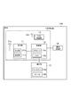
- FIG. 1 is a diagram showing a configuration of a transportation communication system 1 according to an embodiment.
- the traffic communication system 1 includes a vehicle 100 passing through a road and a roadside machine 200 which is a base station installed on the road side of the road.
- the vehicle 100 is an example of a moving body.
- vehicles 100A and 100B are illustrated as the vehicle 100
- roadside machines 200A and 200B are illustrated as the roadside machine 200
- Examples of the vehicle 100 include automobiles such as ordinary automobiles and light automobiles, but any vehicle that passes through a road may be used, for example, a motorcycle (motorcycle) or the like.
- Each vehicle 100 is equipped with an on-board unit 150, which is a mobile station that performs wireless communication.
- the on-board unit 150 performs wireless communication (that is, road-to-vehicle communication) with the roadside unit 200.
- FIG. 1 shows an example in which the on-board unit 150A and the roadside unit 200A perform road-to-vehicle communication, and the on-board unit 150B and the roadside unit 200B perform road-to-vehicle communication.
- the on-board unit 150 may perform wireless communication (that is, vehicle-to-vehicle communication) with another on-board unit 150.
- Each roadside machine 200 is installed around the road. Each roadside machine 200 may be installed at an intersection where two or more roads intersect.
- the roadside unit 200A is installed on the traffic signal 300 or its support, and operates in cooperation with the traffic signal 300.
- the roadside machine 200B is installed on a support column.
- Each roadside machine 200 performs road-to-vehicle communication with the vehicle 100.
- the roadside unit 200A transmits a radio signal including signal information regarding the traffic signal 300 to the vehicle-mounted unit 150.
- wireless communication by broadcasting to an unspecified number of destinations may be used.
- wireless communication by multicast with a specific majority as a destination may be used, or wireless communication by unicast with a specific singular as a destination may be used.
- each roadside unit 200 performs wireless communication (that is, inter-road communication) with another roadside unit 200.
- Inter-road communication is an example of inter-base station communication.
- wireless communication by broadcasting to an unspecified number of destinations may be used.
- wireless communication by multicast with a specific majority as a destination may be used, or wireless communication by unicast with a specific singular as a destination may be used.
- broadcast is used for road-to-road communication
- Each roadside unit 200 is connected to the server 400 via a communication line.
- This communication line may be a wired line or a wireless line.
- the server 400 manages each roadside machine 200.
- FIG. 2 is a diagram showing a configuration of a roadside machine 200 according to an embodiment.
- the roadside unit 200 includes a communication unit 21, a control unit 22, an interface 23, and a GNSS (Global Navigation Satellite System) receiver 24.
- GNSS Global Navigation Satellite System
- the communication unit 21 performs road-to-vehicle communication with the on-board unit 150 and road-to-road communication with another roadside unit 200 (adjacent roadside unit).
- the communication unit 21 has an antenna 21a, a reception unit 21b, and a transmission unit 21c, and performs wireless communication via the antenna 21a.
- the antenna 21a may be an omnidirectional antenna or a directional antenna having directivity.
- the antenna 21a may be an adaptive array antenna whose directivity can be dynamically changed.
- the receiving unit 21b converts the radio signal received by the antenna 21a into received data and outputs the radio signal to the control unit 22.
- the transmission unit 21c converts the transmission data output by the control unit 22 into a wireless signal and transmits it from the antenna 21a.
- the wireless communication method of the communication unit 21 may be a method compliant with the T109 standard of ARIB (Association of Radio Industries and Businesses), or 3GPP (Third Generation Partnership Project) V2X (Vehicle). It may be a method compliant with the wireless LAN (Local Area Network) standard such as the IEEE (Institute of Electrical and Electronics Engineers) 802.11 series.
- the communication unit 21 may be configured to be compatible with two or more of these communication standards.
- an example in which the communication unit 21 performs wireless communication using a method compliant with the ARIB T109 standard will be mainly described.
- the control unit 22 controls various functions of the roadside machine 200.
- the control unit 22 has at least one memory 22b and at least one processor 22a electrically connected to the memory 22b.
- the memory 22b includes a volatile memory and a non-volatile memory, and stores information used for processing in the processor 22a and a program executed by the processor 22a.
- the memory 22b corresponds to a storage unit.
- the processor 22a performs various processes by executing the program stored in the memory 22b.
- the interface 23 is connected to the server 400 via a wired line and / or a wireless line.
- the interface 23 may be electrically connected to the traffic signal 300.
- the GNSS receiver 24 receives a GNSS signal from the GNSS satellite via the antenna 24a.
- the GNSS receiver 24 includes, for example, GPS (Global Positioning System), GLONASS (Global Navigation Satellite System), IRNSS (Indian Regional Navigation Satellite System), IRNSS (Indian Regional Navigation Satellite System), IRNSS (Indian Regional Navigation Satellite System), IRNSS (Indian Regional Navigation Satellite System), IRNSS (Indian Regional Navigation Satellite System). ..
- GPS Global Positioning System
- GLONASS Global Navigation Satellite System
- IRNSS Indian Regional Navigation Satellite System
- IRNSS Indian Regional Navigation Satellite System
- IRNSS Indian Regional Navigation Satellite System
- IRNSS Indian Regional Navigation Satellite System
- IRNSS Indian Regional Navigation Satellite System
- FIG. 3 is a diagram showing a configuration of a vehicle 100 according to an embodiment.
- the vehicle 100 has a communication unit 11, a GNSS receiver 12, a notification unit 13, a drive control unit 14, and a control unit 15.
- the communication unit 11, the GNSS receiver 12, and the control unit 15 constitute an on-board unit 150.
- the communication unit 11 performs road-to-vehicle communication with the roadside unit 200.
- the communication unit 11 may perform wireless communication (that is, vehicle-to-vehicle communication) with another vehicle 100 (another on-board unit 150).
- the communication unit 11 has an antenna 11a, a reception unit 11b, and a transmission unit 11c, and performs wireless communication via the antenna 11a.
- the receiving unit 11b converts the radio signal received by the antenna 11a into received data and outputs the radio signal to the control unit 15.
- the transmission unit 11c converts the transmission data output by the control unit 15 into a wireless signal and transmits it from the antenna 11a.
- the wireless communication method of the communication unit 11 may be a method compliant with the T109 standard of ARIB, a method compliant with the V2X standard of 3GPP, or a wireless LAN standard compliant with the IEEE802.11 series or the like. It may be the method described above.
- the communication unit 11 may be configured to be compatible with two or more of these communication standards.
- an example in which the communication unit 21 performs wireless communication using a method compliant with the ARIB T109 standard will be mainly described.
- the GNSS receiver 12 receives a GNSS signal from the GNSS satellite via the antenna 12a.
- the GNSS receiver 12 includes, for example, a receiver of at least one GNSS among GPS, GLONASS, IRNSS, COMPASS, and Galileo.
- GPS Global System for Mobile Communications
- IRNSS IRNSS
- COMPASS COMPASS
- Galileo Galileo
- the notification unit 13 notifies the driver of the vehicle 100 of the information under the control of the control unit 15.
- the notification unit 13 has a display 13a for displaying information and a speaker 13b for outputting information by voice.
- the drive control unit 14 controls an engine or motor as a power source, a power transmission mechanism, a brake, and the like.
- the drive control unit 14 may perform operation control of the vehicle 100 in cooperation with the control unit 15.
- the control unit 15 controls various functions in the vehicle 100 (vehicle-mounted device 150).
- the control unit 15 has at least one memory 15b and at least one processor 15a electrically connected to the memory 15b.
- the memory 15b includes a volatile memory and a non-volatile memory, and stores information used for processing in the processor 15a and a program executed by the processor 15a.
- the processor 15a performs various processes by executing the program stored in the memory 15b.
- FIG. 4 is a diagram for explaining the operation of the roadside machine 200 according to the embodiment.
- each roadside unit 200 (roadside units 200A and 200B) manages a timer that determines a transmission cycle in inter-road communication.
- This transmission cycle is variable, and a timer that measures such a variable transmission cycle is called an "N second cycle timer".
- the control unit 22 of each roadside unit 200 controls the communication unit 21 so as to transmit a message of inter-road communication in a transmission cycle of N seconds by managing an N-second cycle timer. Such a transmission cycle of N seconds needs to be the same between the adjacent roadside machines 200.
- an offset time is set for each roadside unit 200 so that the transmission timing (transmission time slot) of the roadside communication does not collide between the adjacent roadside units 200.
- the roadside machine 200A is said to be "0 ms", “300 ms”, and "600 ms".
- a message for inter-road communication is transmitted at each timing (each time slot).
- the roadside machine 200A is said to be "100 ms", “400 ms”, and "700 ms".
- a message for inter-road communication is transmitted at each timing (each time slot).
- the transmission cycles (N seconds) of the roadside communication of each roadside machine 200 do not match, and / or if the current values of the N second cycle timers of each roadside machine 200 do not match, they are close to each other.
- the transmission timing (transmission time slot) of the roadside communication may collide between the roadside units 200. Therefore, interference of road-to-road communication may occur between the roadside units 200. That is, when the transmission cycle of the roadside communication is not synchronized between the adjacent roadside units 200, interference of the roadside communication may occur between the roadside units 200.
- the roadside units 200A and 200B perform inter-road communication, which is wireless communication between the roadside units 200.
- the roadside machine 200A is an example of a first base station
- the roadside machine 200B is an example of a second base station.
- the roadside machine 200A transmits a message having a MAC (Medium Access Control) address field (hereinafter, referred to as "inter-road communication message") by inter-road communication.
- Such an inter-road communication message may be referred to as an inter-road communication packet.
- the roadside unit 200B receives an inter-road communication message from the roadside unit 200A.
- the roadside machine 200B is installed around the roadside machine 200A and is within the reach of radio waves from the roadside machine 200A.
- the roadside unit 200A broadcasts an inter-road communication message.
- the inter-road communication message does not include the destination MAC address or includes a broadcast address as the destination MAC address.
- the MAC address is also called a link address.
- the road-to-road communication message includes an identifier that identifies the roadside machine 200A.
- This identifier is an identifier managed in a layer higher than the MAC layer (for example, an application layer). This identifier is different from the MAC address of the roadside machine 200A.
- the source MAC address field for storing the MAC address of the roadside machine 200A does not necessarily have to exist. Specifically, in the case of inter-road communication by broadcasting, it is less necessary to specify the source of the inter-road communication message. Even when it is necessary to specify the source of the inter-road communication message, the source of the inter-road communication message can be specified by the identifier managed in the upper layer.
- the roadside machine 200A stores information different from the MAC address and used for synchronization between the roadside machines 200 in at least a part of the MAC address field included in the roadside communication message.
- this MAC address field is a source MAC address field that stores the MAC address of the roadside machine 200A.
- the synchronization information is transmitted to the other roadside machine 200 (roadside machine 200B) by using the source MAC address field of the roadside communication message without providing an additional field for the existing roadside communication message format. ) Can be transmitted. That is, the synchronization information can be efficiently transmitted to another roadside machine 200 (roadside machine 200B) while maintaining the format of the roadside communication message defined by the existing standard.
- FIG. 5 is a diagram showing an example of the source MAC address field of the inter-road communication message according to the embodiment.
- the source MAC address field is composed of a total of 6 octets, that is, the 0th octet to the 5th octet.
- 6 octets for example, a total of 2 octets, the 4th octet and the 5th octet, are assigned to the synchronization information. Alternatively, all of these 6 octets may be assigned to the synchronization information.
- the 0th to 3rd octets can be assigned to the source MAC address, but a part of the source MAC address may be missing. ..
- the roadside machine 200A may store the complete source MAC address in the source MAC address field instead of storing the synchronization information in the source MAC address field once every plurality of times.
- the roadside machine 200B can supplement the missing part of the source MAC address received later by using the complete source MAC address received earlier.
- the synchronization information stored in the source MAC address of the inter-road communication message includes timer-related information regarding the N-second cycle timer managed by the roadside machine 200A.
- the roadside machine 200B uses the timer-related information stored in the source MAC address of the roadside communication message to manage the N-second cycle timer managed by the roadside machine 200B by the roadside machine 200A. Can be synchronized with.
- the timer-related information includes at least one of a cycle value (hereinafter referred to as "N value") indicating the transmission cycle (N seconds) of the inter-road communication message and the current value of the N-second cycle timer.
- N value a cycle value
- the timer-related information may further include the offset time of transmission of the inter-road communication message.
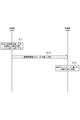
- FIG. 6 is a diagram showing an operation pattern 1 according to an embodiment.
- the roadside machine 200A is started first, and then the roadside machine 200B is started.
- the control unit 22 of the roadside unit 200A determines whether or not the communication unit 21 of the roadside unit 200A has received the roadside communication message.
- the control unit 22 of the roadside machine 200A determines that there is no other roadside machine 200 around the roadside machine 200A, and autonomously determines the N value.
- the N value set here may be, for example, a value notified from the server 400 to the roadside machine 200A.
- FIG. 6 shows an example in which the set N value is 10 seconds.
- step S12 the control unit 22 of the roadside machine 200A controls the communication unit 21 of the roadside machine 200A so as to transmit the inter-road communication message by broadcasting.
- the control unit 22 of the roadside machine 200A controls the communication unit 21 of the roadside machine 200A so that the N value set in step S11 is stored in a part of the source MAC address field of the roadside communication message.
- the communication unit 21 of the roadside unit 200B receives the inter-road communication message from the roadside unit 200A.
- step S13 the control unit 22 of the roadside unit 200B sets the N value of the roadside unit 200B based on the inter-road communication message received by the communication unit 21 of the roadside unit 200B. Specifically, the control unit 22 of the roadside machine 200B matches the N value of the roadside machine 200B with the N value stored in the source MAC address field of the received inter-road communication message. As a result, the N values of the roadside machines 200A and 200B are the same.
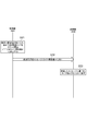
- FIG. 7 is a diagram showing an operation pattern 2 according to one embodiment.
- this operation pattern of the roadside machines 200A and 200B, the roadside machine 200A is started first, and then the roadside machine 200B is started.
- the control unit 22 of the roadside unit 200A determines whether or not the communication unit 21 of the roadside unit 200A has received the roadside communication message.
- the control unit 22 of the roadside unit 200A determines that there is no other roadside unit 200 in the vicinity of the roadside unit 200A, and determines that there is no other roadside unit 200 in the vicinity of the roadside unit 200A. Start timing (counting) autonomously.
- step S22 the control unit 22 of the roadside machine 200A controls the communication unit 21 of the roadside machine 200A so as to transmit the inter-road communication message by broadcasting.
- the control unit 22 of the roadside machine 200A controls the communication unit 21 of the roadside machine 200A so as to store the current value of the N-second cycle timer in a part of the source MAC address field of the inter-road communication message.
- the communication unit 21 of the roadside unit 200B receives the inter-road communication message from the roadside unit 200A.
- FIG. 7 shows an example in which the current value of the N-second cycle timer is 1.2 seconds.
- step S23 the control unit 22 of the roadside unit 200B sets (corrects) the current value of the N-second cycle timer of the roadside unit 200B based on the inter-road communication message received by the communication unit 21 of the roadside unit 200B. Specifically, the control unit 22 of the roadside machine 200B matches the current value of the N-second period timer of the roadside machine 200B with the current value stored in the source MAC address field of the received inter-road communication message. As a result, the current values of the N-second period timers of the roadside machines 200A and 200B are matched.
- GNSS synchronization using the absolute time of GNSS There are two types of methods for synchronizing the frame timing between the roadside units 200: GNSS synchronization using the absolute time of GNSS and air synchronization using inter-road communication.
- FIG. 8 is a diagram showing GNSS synchronization according to this modified example. As shown in FIG. 8, each of the roadside machine 200A and the roadside machine 200B performs frame timing synchronization using the GNSS signal received by the GNSS receiver 24 from the GNSS satellite 600. When each roadside unit 200 can receive a GNSS signal, GNSS synchronization is the most reliable and accurate synchronization method.
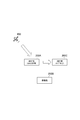
- FIG. 9 is a diagram showing air synchronization according to this modified example.
- the roadside machine 200A performs frame timing synchronization using the GNSS signal received by the GNSS receiver 24 from the GNSS satellite 600.
- the roadside machine 200C cannot receive the GNSS signal from the GNSS satellite 600 and cannot use the GNSS synchronization. Therefore, the roadside machine 200C receives radio waves from the roadside machine 200A, which is an adjacent roadside machine 200, and performs frame timing synchronization using the reception timing. Since the roadside machine 200C using such air synchronization basically controls the frame timing by the self-propelled clock, it is a synchronization method having lower reliability and accuracy than the GNSS synchronization.
- the roadside machine 200B cannot receive the GNSS signal. Further, the roadside machine 200B is located in the vicinity of the roadside machines 200A and 200C, and can receive an inter-road communication message from each of the roadside machines 200A and 200C.
- the roadside machine 200B sets the roadside machine 200A during GNSS synchronization as the air synchronization target of the roadside machine 200B rather than the roadside machine 200C during air synchronization. That is, it is not preferable that the roadside machine 200B sets the roadside machine 200C during air synchronization as the air synchronization target of the roadside machine 200B.
- the synchronization information stored in the source MAC address of the inter-road communication message transmitted by the roadside unit 200A includes the synchronization type information regarding the synchronization target of the roadside unit 200A.
- the synchronization type information regarding the synchronization target of the roadside machine 200A is information indicating GNSS synchronization.
- the information indicating GNSS synchronization may be information indicating that it is not air synchronization.
- the synchronization information stored in the source MAC address of the inter-road communication message transmitted by the roadside machine 200C includes the synchronization type information regarding the synchronization target of the roadside machine 200C.
- the synchronization type information regarding the synchronization target of the roadside machine 200C is information indicating air synchronization.
- the information indicating air synchronization may be information indicating that it is not GNSS synchronization.
- FIG. 10 is a diagram showing an operation pattern 1 according to this modified example.
- the roadside machines 200A, 200B, and 200C are started first, and then the roadside machine 200B is started. Further, it is assumed that the roadside units 200B and 200C cannot receive the GNSS signal (that is, GNSS synchronization is not possible).
- step S31 the control unit 22 of the roadside machine 200C controls the communication unit 21 of the roadside machine 200C so as to transmit the inter-road communication message by broadcasting.
- the control unit 22 of the roadside machine 200C stores the synchronization type information indicating that the roadside machine 200C is in air synchronization in a part of the source MAC address field of the roadside communication message. It controls the communication unit 21 of 200C.
- the communication unit 21 of the roadside unit 200B receives the inter-road communication message from the roadside unit 200A.
- step S32 the control unit 22 of the roadside machine 200A controls the communication unit 21 of the roadside machine 200A so as to broadcast the inter-road communication message.
- the control unit 22 of the roadside machine 200A uses a part of the source MAC address field of the roadside communication message to provide synchronization type information indicating that the roadside machine 200A is in GNSS synchronization (not in air synchronization).
- the communication unit 21 of the roadside machine 200A is controlled so as to be stored in.
- the communication unit 21 of the roadside unit 200B receives the inter-road communication message from the roadside unit 200A.
- step S33 the control unit 22 of the roadside machine 200B sets the air synchronization target of the roadside machine 200B based on the synchronization type information stored in the MAC address field of the roadside communication message received in steps S31 and S32.
- the control unit 22 of the roadside unit 200B uses the roadside unit 200C as the roadside unit because the synchronization type information stored in the MAC address field of the roadside communication message received from the roadside unit 200C is information indicating air synchronization. It is determined not to be set as the synchronization target of the 200B (that is, excluded from the synchronization target of the roadside machine 200B).
- the control unit 22 of the roadside machine 200A uses the roadside machine 200A as the roadside machine because the synchronization type information stored in the MAC address field of the roadside communication message received from the roadside machine 200A is the information indicating GNSS synchronization. It is decided to set it as an air synchronization target of 200B.
- FIG. 11 is a diagram showing an operation pattern 2 according to this modified example.
- the roadside machines 200A, 200B, and 200C are started first, and then the roadside machine 200B is started. Further, it is assumed that the roadside units 200B and 200C cannot receive the GNSS signal (that is, GNSS synchronization is not possible).
- step S41 the control unit 22 of the roadside machine 200C controls the communication unit 21 of the roadside machine 200C so as to transmit the inter-road communication message by broadcasting.
- the control unit 22 of the roadside machine 200C stores the synchronization type information indicating that the roadside machine 200C is in air synchronization in a part of the source MAC address field of the roadside communication message. It controls the communication unit 21 of 200C.
- the communication unit 21 of the roadside unit 200B receives the inter-road communication message from the roadside unit 200A.
- step S42 the control unit 22 of the roadside machine 200A controls the communication unit 21 of the roadside machine 200A so as to broadcast an inter-road communication message.
- the control unit 22 of the roadside machine 200A uses a part of the source MAC address field of the roadside communication message to provide synchronization type information indicating that the roadside machine 200A is in GNSS synchronization (not in air synchronization).
- the communication unit 21 of the roadside machine 200A is controlled so as to be stored in. However, the roadside machine 200A is far from the roadside machine 200B, and the inter-road communication message from the roadside machine 200A is not received by the roadside machine 200B.
- step S43 the control unit 22 of the roadside machine 200B sets the air synchronization target of the roadside machine 200B based on the synchronization type information stored in the MAC address field of the roadside communication message received from the roadside machine 200C in step S41. do.
- the control unit 22 of the roadside unit 200B uses the roadside unit 200C as the roadside unit because the synchronization type information stored in the MAC address field of the roadside communication message received from the roadside unit 200C is information indicating air synchronization. It is determined not to be set as the synchronization target of the 200B (that is, excluded from the synchronization target of the roadside machine 200B).
- the control unit 22 of the roadside machine 200B controls the frame timing by the self-propelled clock.
- the control unit 22 of the roadside machine 200B may determine that the operation of the roadside machine 200B is to be stopped and stop the transmission of radio waves.
- the communication system is the transportation communication system 1
- the communication system may be another communication system such as a cellular communication system.
- the server 400 may be an edge server arranged near the roadside machine 200.
- Such an edge server may be regarded as a part of the roadside machine 200.
- the edge server is provided between the roadside machine 200 and the Internet, and controls roads in an area limited to a predetermined range.
- the edge server may be connected to the roadside unit 200 via a LAN (Local Area Network) without going through a WAN (Wide Area Network).
- LAN Local Area Network
- WAN Wide Area Network
- a program for causing a computer to execute each process according to the above-described embodiment may be provided.
- the program may be recorded on a computer-readable medium.
- Computer-readable media allow you to install programs on your computer.
- the computer-readable medium on which the program is recorded may be a non-transient recording medium.
- the non-transient recording medium is not particularly limited, but may be, for example, a recording medium such as a CD-ROM or a DVD-ROM.
Landscapes
- Engineering & Computer Science (AREA)
- Computer Networks & Wireless Communication (AREA)
- Signal Processing (AREA)
- Traffic Control Systems (AREA)
- Mobile Radio Communication Systems (AREA)
Abstract
路側機200間の無線通信である路路間通信を行う交通通信システム1は、MACアドレスフィールドを有するメッセージを路路間通信により送信する路側機200Aと、メッセージを路路間通信により受信する路側機200Bとを有する。路側機200Aは、MACアドレスと異なる情報であって路側機200間の同期に用いる同期用情報をMACアドレスフィールドの少なくとも一部に格納する。
Description
本発明は、通信システム、基地局、及び通信制御方法に関する。
近年、交通事故の危険を回避可能な技術として高度道路交通システム(ITS:Intelligent Transport System)が注目されている。
そのようなシステムの1つとして、非特許文献1には、路側に設置される基地局である路側機と、車両に搭載される移動局である車載機とを有し、路側機及び車載機が無線通信を行うシステムが記載されている。
ARIB STD-T109 1.3版 「700MHz帯高度道路交通システム」
第1の態様に係る通信システムは、基地局間の無線通信である基地局間通信を行う通信システムであって、MAC(Medium Access Control)アドレスフィールドを有するメッセージを前記基地局間通信により送信する第1基地局と、前記メッセージを前記基地局間通信により受信する第2基地局とを備える。前記第1基地局は、MACアドレスと異なる情報であって基地局間の同期に用いる同期用情報を前記MACアドレスフィールドの少なくとも一部に格納する。
第2の態様に係る基地局は、基地局間の無線通信である基地局間通信を行う基地局であって、MAC(Medium Access Control)アドレスフィールドを有するメッセージを前記基地局間通信により送信する通信部を備える。前記通信部は、MACアドレスと異なる情報であって基地局間の同期に用いる同期用情報を前記MACアドレスフィールドの少なくとも一部に格納する。
第3の態様に係る基地局は、基地局間の無線通信である基地局間通信を行う基地局であって、MAC(Medium Access Control)アドレスフィールドを有するメッセージを前記基地局間通信により受信する通信部を備える。前記通信部は、MACアドレスと異なる情報であって基地局間の同期に用いる同期用情報が前記MACアドレスフィールドの少なくとも一部に格納された前記メッセージを受信する。
第4の態様に係る通信制御方法は、通信システムにおいて基地局間の無線通信である基地局間通信を行う通信制御方法であって、第1基地局が、MAC(Medium Access Control)アドレスフィールドを有するメッセージを前記基地局間通信により送信することと、第2基地局が、前記メッセージを前記基地局間通信により受信することとを有する。前記第1基地局は、MACアドレスと異なる情報であって基地局間の同期に用いる同期用情報を前記MACアドレスフィールドの少なくとも一部に格納する。
上述したような通信システムにおいて、隣接する基地局間で同期がとれていないと、基地局間で干渉が発生するという問題がある。
そこで、本開示は、効率的に基地局間の同期をとることを可能とすることを目的とする。
一実施形態に係る通信システムである交通通信システムについて図面を参照しながら説明する。なお、以下の図面の記載において、同一又は類似の部分には、同一又は類似の符号を付している。
(交通通信システムの構成)
まず、一実施形態に係る交通通信システムの構成について説明する。図1は、一実施形態に係る交通通信システム1の構成を示す図である。
まず、一実施形態に係る交通通信システムの構成について説明する。図1は、一実施形態に係る交通通信システム1の構成を示す図である。
図1に示すように、交通通信システム1は、道路を通る車両100と、道路の路側に設置される基地局である路側機200とを有する。車両100は、移動体の一例である。
図1において、車両100として車両100A及び100Bを例示し、路側機200として路側機200A及び200Bを例示している。車両100としては、普通自動車や軽自動車等の自動車を例示しているが、道路を通る車両であればよく、例えば自動二輪車(オートバイ)等であってもよい。
各車両100には、無線通信を行う移動局である車載機150が搭載されている。車載機150は、路側機200との無線通信(すなわち、路車間通信)を行う。図1において、車載機150A及び路側機200Aが路車間通信を行うとともに、車載機150B及び路側機200Bが路車間通信を行う一例を示している。車載機150は、他の車載機150との無線通信(すなわち、車車間通信)を行ってもよい。
各路側機200は、道路の周辺に設置されている。各路側機200は、2以上の道路が交差する交差点に設置されてもよい。路側機200Aは、交通信号機300又はその支柱に設置されており、交通信号機300と連携して動作する。路側機200Bは、支柱に設置されている。
各路側機200は、車両100との路車間通信を行う。例えば、路側機200Aは、交通信号機300に関する信号情報を含む無線信号を車載機150に送信する。このような路車間通信には、不特定多数を宛先とするブロードキャストによる無線通信が用いられてもよい。或いは、路車間通信には、特定多数を宛先とするマルチキャストによる無線通信が用いられてもよいし、特定単数を宛先とするユニキャストによる無線通信が用いられてもよい。
また、各路側機200は、他の路側機200との無線通信(すなわち、路路間通信)を行う。路路間通信は、基地局間通信の一例である。このような路路間通信には、不特定多数を宛先とするブロードキャストによる無線通信が用いられてもよい。或いは、路路間通信には、特定多数を宛先とするマルチキャストによる無線通信が用いられてもよいし、特定単数を宛先とするユニキャストによる無線通信が用いられてもよい。以下において、路路間通信にブロードキャストが用いられる一例について主として説明する。
各路側機200は、通信回線を介してサーバ400に接続される。この通信回線は、有線回線であってもよいし、無線回線であってもよい。サーバ400は、各路側機200を管理する。
(路側機の構成)
次に、一実施形態に係る路側機200の構成について説明する。図2は、一実施形態に係る路側機200の構成を示す図である。
次に、一実施形態に係る路側機200の構成について説明する。図2は、一実施形態に係る路側機200の構成を示す図である。
図2に示すように、路側機200は、通信部21と、制御部22と、インターフェイス23と、GNSS(Global Navigation Satellite System)受信機24とを有する。
通信部21は、制御部22の制御下で、車載機150との路車間通信を行うとともに、他の路側機200(隣接路側機)との路路間通信を行う。
通信部21は、アンテナ21aと、受信部21bと、送信部21cとを有し、アンテナ21aを介して無線通信を行う。アンテナ21aは、無指向性アンテナであってもよいし、指向性を有する指向性アンテナであってもよい。アンテナ21aは、指向性を動的に変更可能なアダプティブアレイアンテナであってもよい。受信部21bは、アンテナ21aが受信する無線信号を受信データに変換して制御部22に出力する。送信部21cは、制御部22が出力する送信データを無線信号に変換してアンテナ21aから送信する。
通信部21の無線通信方式は、ARIB(Association of Radio Industries and Businesses)のT109規格に準拠した方式であってもよいし、3GPP(Third Generation Partnership Project)のV2X(Vehicle-to-everything)規格に準拠した方式であってもよいし、IEEE(Institute of Electrical and Electronics Engineers)802.11シリーズ等の無線LAN(Local Area Network)規格に準拠した方式であってもよい。通信部21は、これらの通信規格のうち2以上の通信規格に対応可能に構成されていてもよい。以下において、通信部21がARIBのT109規格に準拠した方式を用いて無線通信を行う一例について主として説明する。
制御部22は、路側機200における各種の機能を制御する。制御部22は、少なくとも1つのメモリ22bと、メモリ22bと電気的に接続された少なくとも1つのプロセッサ22aとを有する。メモリ22bは、揮発性メモリ及び不揮発性メモリを含み、プロセッサ22aにおける処理に用いる情報と、プロセッサ22aにより実行されるプログラムとを記憶する。メモリ22bは、記憶部に相当する。プロセッサ22aは、メモリ22bに記憶されたプログラムを実行することにより各種の処理を行う。
インターフェイス23は、有線回線及び/又は無線回線を介してサーバ400と接続される。インターフェイス23は、交通信号機300と電気的に接続されてもよい。
GNSS受信機24は、GNSS衛星からアンテナ24aを介してGNSS信号を受信する。GNSS受信機24は、例えば、GPS(Grobal Positioning System)、GLONASS(Global Navigation Satellite System)、IRNSS(Indian Regional Navigational Satellite System)、COMPASS、Galileoのうち少なくとも1つのGNSSの受信機を含んで構成される。以下において、GNSS受信機24がGPS受信機を含む一例について主として説明する。
(車両の構成)
次に、一実施形態に係る車両100の構成について説明する。図3は、一実施形態に係る車両100の構成を示す図である。
次に、一実施形態に係る車両100の構成について説明する。図3は、一実施形態に係る車両100の構成を示す図である。
図3に示すように、車両100は、通信部11と、GNSS受信機12と、通知部13と、駆動制御部14と、制御部15とを有する。通信部11、GNSS受信機12、及び制御部15は、車載機150を構成する。
通信部11は、路側機200との路車間通信を行う。通信部11は、他の車両100(他の車載機150)との無線通信(すなわち、車車間通信)を行ってもよい。具体的には、通信部11は、アンテナ11aと、受信部11bと、送信部11cとを有し、アンテナ11aを介して無線通信を行う。受信部11bは、アンテナ11aが受信する無線信号を受信データに変換して制御部15に出力する。送信部11cは、制御部15が出力する送信データを無線信号に変換してアンテナ11aから送信する。
通信部11の無線通信方式は、ARIBのT109規格に準拠した方式であってもよいし、3GPPのV2X規格に準拠した方式であってもよいし、IEEE802.11シリーズ等の無線LAN規格に準拠した方式であってもよい。通信部11は、これらの通信規格のうち2以上の通信規格に対応可能に構成されていてもよい。以下において、通信部21がARIBのT109規格に準拠した方式を用いて無線通信を行う一例について主として説明する。
GNSS受信機12は、GNSS衛星からアンテナ12aを介してGNSS信号を受信する。GNSS受信機12は、例えば、GPS、GLONASS、IRNSS、COMPASS、Galileoのうち少なくとも1つのGNSSの受信機を含んで構成される。以下において、GNSS受信機12がGPS受信機を含む一例について主として説明する。
通知部13は、制御部15の制御下で、車両100の運転者に対する情報の通知を行う。通知部13は、情報を表示するディスプレイ13aと、情報を音声出力するスピーカ13bとを有する。
駆動制御部14は、動力源としてのエンジン又はモータ、動力伝達機構、及びブレーキ等を制御する。車両100が自動運転車両である場合、駆動制御部14は、制御部15と連携して車両100の運転制御を行ってもよい。
制御部15は、車両100(車載機150)における各種の機能を制御する。制御部15は、少なくとも1つのメモリ15bと、メモリ15bと電気的に接続された少なくとも1つのプロセッサ15aとを有する。メモリ15bは、揮発性メモリ及び不揮発性メモリを含み、プロセッサ15aにおける処理に用いる情報及びプロセッサ15aにより実行されるプログラムを記憶する。プロセッサ15aは、メモリ15bに記憶されたプログラムを実行することにより各種の処理を行う。
(路側機の動作)
次に、一実施形態に係る路側機200の動作について説明する。図4は、一実施形態に係る路側機200の動作を説明するための図である。
次に、一実施形態に係る路側機200の動作について説明する。図4は、一実施形態に係る路側機200の動作を説明するための図である。
図4に示すように、各路側機200(路側機200A及び200B)の制御部22は、路路間通信における送信周期を定めるタイマを管理する。この送信周期は可変であり、このような可変の送信周期を計時するタイマを「N秒周期タイマ」と呼ぶ。
各路側機200の制御部22は、N秒周期タイマを管理することにより、N秒の送信周期で路路間通信のメッセージを送信するように通信部21を制御する。このようなN秒の送信周期は、近接する路側機200間で一致している必要がある。
また、近接する路側機200間で路路間通信の送信タイミング(送信時間スロット)が衝突しないように、各路側機200にオフセット時間が設定される。
例えば、路側機200Aに設定されたオフセット時間が「0ms」であって、N秒の送信周期が「300ms」である場合、路側機200Aは、「0ms」、「300ms」、及び「600ms」といった各タイミング(各時間スロット)で路路間通信のメッセージを送信する。
一方、路側機200Bに設定されたオフセット時間が「100ms」であって、N秒の送信周期が「300ms」である場合、路側機200Aは、「100ms」、「400ms」、及び「700ms」といった各タイミング(各時間スロット)で路路間通信のメッセージを送信する。
このように、各路側機200の路路間通信の送信周期(N秒)が一致しており、且つ、各路側機200のN秒周期タイマの現在値が一致している場合、近接する路側機200間で路路間通信の送信タイミング(送信時間スロット)が衝突しない。そのため、路路間通信の干渉が路側機200間で生じることを防止できる。
しかしながら、各路側機200の路路間通信の送信周期(N秒)が一致していない場合、及び/又は、各路側機200のN秒周期タイマの現在値が一致していない場合、近接する路側機200間で路路間通信の送信タイミング(送信時間スロット)が衝突し得る。そのため、路路間通信の干渉が路側機200間で生じ得る。つまり、近接する路側機200間で路路間通信の送信周期に関する同期がとれていない場合、路路間通信の干渉が路側機200間で生じ得る。
以下において、路路間通信の送信周期に関する同期をとるための路側機200の動作について説明する。
一実施形態に係る路側機200A及び200Bは、路側機200間の無線通信である路路間通信を行う。路側機200Aは第1基地局の一例であって、路側機200Bは第2基地局の一例である。
路側機200Aは、MAC(Medium Access Control)アドレスフィールドを有するメッセージ(以下、「路路間通信メッセージ」と呼ぶ)を路路間通信により送信する。このような路路間通信メッセージは、路路間通信パケットと呼ばれてもよい。路側機200Bは、路側機200Aからの路路間通信メッセージを受信する。具体的には、路側機200Bは、路側機200Aの周辺に設置されており、路側機200Aからの電波の到達範囲内にある。
一実施形態において、路側機200Aは、路路間通信メッセージをブロードキャストで送信する。例えば、路路間通信メッセージは、宛先MACアドレスを含まない、又は宛先MACアドレスとしてブロードキャストアドレスを含む。なお、MACアドレスは、リンクアドレスとも呼ばれる。
また、路路間通信メッセージは、路側機200Aを識別する識別子を含む。この識別子は、MAC層よりも上位層(例えば、アプリケーション層)で管理される識別子である。なお、この識別子は、路側機200AのMACアドレスとは異なるものである。
このような前提下において、路側機200Aが送信する路路間通信メッセージにおいて、路側機200AのMACアドレスを格納する送信元MACアドレスフィールドは、必ずしも存在しなくてもよい。具体的には、ブロードキャストによる路路間通信の場合、路路間通信メッセージの送信元を特定する必要性が低い。路路間通信メッセージの送信元を特定する必要がある場合であっても、上位層で管理される識別子により路路間通信メッセージの送信元を特定可能である。
路側機200Aは、MACアドレスと異なる情報であって路側機200間の同期に用いる同期用情報を、路路間通信メッセージに含まれるMACアドレスフィールドの少なくとも一部に格納する。一実施形態において、このMACアドレスフィールドは、路側機200AのMACアドレスを格納する送信元MACアドレスフィールドである。
これにより、既存の路路間通信メッセージのフォーマットに対して追加のフィールドを設けることなく、路路間通信メッセージの送信元MACアドレスフィールドを用いて同期用情報を他の路側機200(路側機200B)に伝達できる。すなわち、既存の規格で規定される路路間通信メッセージのフォーマットを維持しつつ、同期用情報を他の路側機200(路側機200B)に効率的に伝達できる。
図5は、一実施形態に係る路路間通信メッセージの送信元MACアドレスフィールドの一例を示す図である。
図5に示すように、送信元MACアドレスフィールドは、第0オクテット乃至第5オクテットの合計6オクテットで構成される。これら6オクテットのうち、例えば第4オクテット及び第5オクテットの合計2オクテットが同期用情報に割り当てられる。或いは、これら6オクテットの全部が同期用情報に割り当てられてもよい。
第4オクテット及び第5オクテットの合計2オクテットが同期用情報に割り当てられる場合、第0オクテット乃至第3オクテットを送信元MACアドレスに割り当てることができるが、送信元MACアドレスの一部が欠落し得る。しかし、上述したように、送信元MACアドレスは重要な情報ではないため、その一部が欠落してもよい。なお、路側機200Aは、複数回に1回の割合で、同期用情報を送信元MACアドレスフィールドに格納せずに、完全な送信元MACアドレスを送信元MACアドレスフィールドに格納してもよい。これにより、路側機200Bは、先に受信した完全な送信元MACアドレスを用いて、後に受信した送信元MACアドレスの欠落部分を補完できる。
一実施形態において、路路間通信メッセージの送信元MACアドレスに格納される同期用情報は、路側機200Aが管理するN秒周期タイマに関するタイマ関連情報を含む。これにより、路側機200Bは、路路間通信メッセージの送信元MACアドレスに格納されるタイマ関連情報を用いて、路側機200Bが管理するN秒周期タイマを路側機200Aが管理するN秒周期タイマと同期させることができる。
例えば、タイマ関連情報は、路路間通信メッセージの送信周期(N秒)を示す周期値(以下、「N値」と呼ぶ)及びN秒周期タイマの現在値のうち少なくとも一方を含む。タイマ関連情報は、路路間通信メッセージの送信のオフセット時間をさらに含んでもよい。
(1)動作パターン1
図6は、一実施形態に係る動作パターン1を示す図である。本動作パターンにおいて、路側機200A及び200Bのうち、路側機200Aが先に起動し、その後に路側機200Bが起動するものとする。
図6は、一実施形態に係る動作パターン1を示す図である。本動作パターンにおいて、路側機200A及び200Bのうち、路側機200Aが先に起動し、その後に路側機200Bが起動するものとする。
図6に示すように、ステップS11において、路側機200Aが起動すると、路側機200Aの制御部22は、路側機200Aの通信部21が路路間通信メッセージを受信したか否かを判定する。路側機200Aの通信部21が路路間通信メッセージを受信できない場合、路側機200Aの制御部22は、路側機200Aの周辺に他の路側機200が存在しないと判定し、N値を自律的に設定する。ここで設定されるN値は、例えばサーバ400から路側機200Aに通知される値であってもよい。図6において、設定されるN値が10秒である一例を示している。
ステップS12において、路側機200Aの制御部22は、路路間通信メッセージをブロードキャストで送信するように路側機200Aの通信部21を制御する。ここで、路側機200Aの制御部22は、ステップS11で設定したN値を路路間通信メッセージの送信元MACアドレスフィールドの一部に格納するように路側機200Aの通信部21を制御する。路側機200Bの通信部21は、路側機200Aからの路路間通信メッセージを受信する。
ステップS13において、路側機200Bの制御部22は、路側機200Bの通信部21が受信した路路間通信メッセージに基づいて路側機200BのN値を設定する。具体的には、路側機200Bの制御部22は、路側機200BのN値を、受信した路路間通信メッセージの送信元MACアドレスフィールドに格納されたN値と一致させる。これにより、路側機200A及び200BのそれぞれのN値が一致することになる。
(2)動作パターン2
図7は、一実施形態に係る動作パターン2を示す図である。本動作パターンにおいて、路側機200A及び200Bのうち、路側機200Aが先に起動し、その後に路側機200Bが起動するものとする。
図7は、一実施形態に係る動作パターン2を示す図である。本動作パターンにおいて、路側機200A及び200Bのうち、路側機200Aが先に起動し、その後に路側機200Bが起動するものとする。
図7に示すように、ステップS21において、路側機200Aが起動すると、路側機200Aの制御部22は、路側機200Aの通信部21が路路間通信メッセージを受信したか否かを判定する。路側機200Aの通信部21が路路間通信メッセージを受信できない場合、路側機200Aの制御部22は、路側機200Aの周辺に他の路側機200が存在しないと判定し、N秒周期タイマの計時(カウント)を自律的に開始する。
ステップS22において、路側機200Aの制御部22は、路路間通信メッセージをブロードキャストで送信するように路側機200Aの通信部21を制御する。ここで、路側機200Aの制御部22は、N秒周期タイマの現在値を路路間通信メッセージの送信元MACアドレスフィールドの一部に格納するように路側機200Aの通信部21を制御する。路側機200Bの通信部21は、路側機200Aからの路路間通信メッセージを受信する。図7において、N秒周期タイマの現在値が1.2秒である一例を示している。
ステップS23において、路側機200Bの制御部22は、路側機200Bの通信部21が受信した路路間通信メッセージに基づいて路側機200BのN秒周期タイマの現在値を設定(修正)する。具体的には、路側機200Bの制御部22は、路側機200BのN秒周期タイマの現在値を、受信した路路間通信メッセージの送信元MACアドレスフィールドに格納された現在値と一致させる。これにより、路側機200A及び200BのそれぞれのN秒周期タイマの現在値が一致することになる。
(変更例)
次に、上述した実施形態の変更例について説明する。上述した実施形態において、路側機200間でN秒周期タイマを同期させる一例について説明した。本変更例は、路側機200間でフレームタイミングを同期させるための実施例である。
次に、上述した実施形態の変更例について説明する。上述した実施形態において、路側機200間でN秒周期タイマを同期させる一例について説明した。本変更例は、路側機200間でフレームタイミングを同期させるための実施例である。
路側機200間でフレームタイミングを同期させるための方法としては、GNSSの絶対時刻を用いたGNSS同期及び路路間通信を用いたエア同期の2種類の方法がある。
図8は、本変更例に係るGNSS同期を示す図である。図8に示すように、路側機200A及び路側機200Bのそれぞれは、GNSS受信機24がGNSS衛星600から受信するGNSS信号を用いてフレームタイミング同期を行う。各路側機200がGNSS信号を受信可能である場合、GNSS同期が最も信頼性及び精度が高い同期方法である。
図9は、本変更例に係るエア同期を示す図である。図9に示すように、路側機200AはGNSS受信機24がGNSS衛星600から受信するGNSS信号を用いてフレームタイミング同期を行う。一方、路側機200Cは、GNSS衛星600からGNSS信号を受信できず、GNSS同期を用いることができない。このため、路側機200Cは、隣接路側機200である路側機200Aからの電波を受信し、その受信タイミングを用いてフレームタイミング同期を行う。このようなエア同期を用いる路側機200Cは、基本的には自走クロックによりフレームタイミングを制御するため、GNSS同期に比べて信頼性及び精度が低い同期方法である。
図9に示す状況下において、路側機200Bは、GNSS信号を受信できないものとする。また、路側機200Bは、路側機200A及び200Cの周辺にあり、路側機200A及び200Cのそれぞれから路路間通信メッセージを受信し得るものとする。
この場合、路側機200Bのエア同期対象の候補としては、路側機200A及び200Cの2つがある。ここで、路側機200Bは、エア同期中の路側機200Cよりも、GNSS同期中の路側機200Aを路側機200Bのエア同期対象として設定することが好ましい。すなわち、路側機200Bは、エア同期中の路側機200Cを路側機200Bのエア同期対象として設定することは好ましくない。
以下において、エア同期対象を適切に設定可能とするための路側機200の動作について説明する。
本変更例において、路側機200Aが送信する路路間通信メッセージの送信元MACアドレスに格納される同期用情報は、路側機200Aの同期対象に関する同期種別情報を含む。図9に示す例において、路側機200Aの同期対象に関する同期種別情報は、GNSS同期を示す情報である。GNSS同期を示す情報は、エア同期ではないことを示す情報であってもよい。
同様に、路側機200Cが送信する路路間通信メッセージの送信元MACアドレスに格納される同期用情報は、路側機200Cの同期対象に関する同期種別情報を含む。図9に示す例において、路側機200Cの同期対象に関する同期種別情報は、エア同期を示す情報である。エア同期を示す情報は、GNSS同期ではないことを示す情報であってもよい。
(1)動作パターン1
図10は、本変更例に係る動作パターン1を示す図である。本動作パターンにおいて、路側機200A、200B、及び200Cのうち、路側機200A及び200Cが先に起動し、その後に路側機200Bが起動するものとする。また、路側機200B及び200Cは、GNSS信号を受信不可(すなわち、GNSS同期が不可)であるものとする。
図10は、本変更例に係る動作パターン1を示す図である。本動作パターンにおいて、路側機200A、200B、及び200Cのうち、路側機200A及び200Cが先に起動し、その後に路側機200Bが起動するものとする。また、路側機200B及び200Cは、GNSS信号を受信不可(すなわち、GNSS同期が不可)であるものとする。
ステップS31において、路側機200Cの制御部22は、路路間通信メッセージをブロードキャストで送信するように路側機200Cの通信部21を制御する。ここで、路側機200Cの制御部22は、路側機200Cがエア同期中であることを示す同期種別情報を、路路間通信メッセージの送信元MACアドレスフィールドの一部に格納するように路側機200Cの通信部21を制御する。路側機200Bの通信部21は、路側機200Aからの路路間通信メッセージを受信する。
ステップS32において、路側機200Aの制御部22は、路路間通信メッセージをブロードキャストで送信するように路側機200Aの通信部21を制御する。ここで、路側機200Aの制御部22は、路側機200AがGNSS同期中である(エア同期中ではない)ことを示す同期種別情報を、路路間通信メッセージの送信元MACアドレスフィールドの一部に格納するように路側機200Aの通信部21を制御する。路側機200Bの通信部21は、路側機200Aからの路路間通信メッセージを受信する。
ステップS33において、路側機200Bの制御部22は、ステップS31及びS32で受信した路路間通信メッセージのMACアドレスフィールドに格納された同期種別情報に基づいて路側機200Bのエア同期対象を設定する。ここで、路側機200Bの制御部22は、路側機200Cから受信した路路間通信メッセージのMACアドレスフィールドに格納された同期種別情報がエア同期を示す情報であるため、路側機200Cを路側機200Bのエア同期対象として設定しない(すなわち、路側機200Bの同期対象から除外する)よう決定する。一方で、路側機200Aの制御部22は、路側機200Aから受信した路路間通信メッセージのMACアドレスフィールドに格納された同期種別情報がGNSS同期を示す情報であるため、路側機200Aを路側機200Bのエア同期対象として設定するよう決定する。
(2)動作パターン2
図11は、本変更例に係る動作パターン2を示す図である。本動作パターンにおいて、路側機200A、200B、及び200Cのうち、路側機200A及び200Cが先に起動し、その後に路側機200Bが起動するものとする。また、路側機200B及び200Cは、GNSS信号を受信不可(すなわち、GNSS同期が不可)であるものとする。
図11は、本変更例に係る動作パターン2を示す図である。本動作パターンにおいて、路側機200A、200B、及び200Cのうち、路側機200A及び200Cが先に起動し、その後に路側機200Bが起動するものとする。また、路側機200B及び200Cは、GNSS信号を受信不可(すなわち、GNSS同期が不可)であるものとする。
ステップS41において、路側機200Cの制御部22は、路路間通信メッセージをブロードキャストで送信するように路側機200Cの通信部21を制御する。ここで、路側機200Cの制御部22は、路側機200Cがエア同期中であることを示す同期種別情報を、路路間通信メッセージの送信元MACアドレスフィールドの一部に格納するように路側機200Cの通信部21を制御する。路側機200Bの通信部21は、路側機200Aからの路路間通信メッセージを受信する。
ステップS42において、路側機200Aの制御部22は、路路間通信メッセージをブロードキャストで送信するように路側機200Aの通信部21を制御する。ここで、路側機200Aの制御部22は、路側機200AがGNSS同期中である(エア同期中ではない)ことを示す同期種別情報を、路路間通信メッセージの送信元MACアドレスフィールドの一部に格納するように路側機200Aの通信部21を制御する。しかし、路側機200Aが路側機200Bの遠くにあり、路側機200Aからの路路間通信メッセージは路側機200Bにおいて受信されない。
ステップS43において、路側機200Bの制御部22は、ステップS41で路側機200Cから受信した路路間通信メッセージのMACアドレスフィールドに格納された同期種別情報に基づいて路側機200Bのエア同期対象を設定する。ここで、路側機200Bの制御部22は、路側機200Cから受信した路路間通信メッセージのMACアドレスフィールドに格納された同期種別情報がエア同期を示す情報であるため、路側機200Cを路側機200Bのエア同期対象として設定しない(すなわち、路側機200Bの同期対象から除外する)よう決定する。この場合、路側機200Bの制御部22は、自走クロックによりフレームタイミングを制御する。或いは、路側機200Bの制御部22は、路側機200Bの運用を停止すると判定し、電波の送信を停止してもよい。
(その他の実施形態)
上述した実施形態において、通信システムが交通通信システム1である一例について説明したが、通信システムは、セルラ通信システム等の他の通信システムであってもよい。
上述した実施形態において、通信システムが交通通信システム1である一例について説明したが、通信システムは、セルラ通信システム等の他の通信システムであってもよい。
また、上述した実施形態において、サーバ400は、路側機200の近くに配置されるエッジサーバであってもよい。このようなエッジサーバを路側機200の一部とみなしてもよい。エッジサーバは、路側機200とインターネットとの間に設けられ、所定範囲に限定されたエリア内の道路を管轄する。エッジサーバは、WAN(Wide Area Network)を介さずに、LAN(Local Area Network)を介して路側機200と接続されてもよい。
上述した実施形態に係る各処理をコンピュータに実行させるプログラムが提供されてもよい。プログラムは、コンピュータ読取り可能媒体に記録されていてもよい。コンピュータ読取り可能媒体を用いれば、コンピュータにプログラムをインストールすることが可能である。ここで、プログラムが記録されたコンピュータ読取り可能媒体は、非一過性の記録媒体であってもよい。非一過性の記録媒体は、特に限定されるものではないが、例えば、CD-ROMやDVD-ROM等の記録媒体であってもよい。
以上、図面を参照して実施形態について詳しく説明したが、具体的な構成は上述のものに限られることはなく、要旨を逸脱しない範囲内において様々な設計変更等をすることが可能である。
本願は、日本国特許出願第2020-077777号(2020年4月24日出願)の優先権を主張し、その内容の全てが本願明細書に組み込まれている。
Claims (15)
- 基地局間の無線通信である基地局間通信を行う通信システムであって、
MAC(Medium Access Control)アドレスフィールドを有するメッセージを前記基地局間通信により送信する第1基地局と、
前記メッセージを前記基地局間通信により受信する第2基地局と、を備え、
前記第1基地局は、MACアドレスと異なる情報であって基地局間の同期に用いる同期用情報を前記MACアドレスフィールドの少なくとも一部に格納する、通信システム。 - 前記第1基地局及び前記第2基地局のそれぞれは、前記基地局間通信における送信周期を定めるタイマを管理し、
前記同期用情報は、前記第1基地局が管理する前記タイマに関するタイマ関連情報を含む、請求項1に記載の通信システム。 - 前記タイマ関連情報は、前記送信周期を示す周期値を含む、請求項2に記載の通信システム。
- 前記第2基地局は、前記第2基地局の前記送信周期を、前記第1基地局から受信した前記メッセージの前記MACアドレスフィールドに格納された前記周期値が示す前記送信周期と一致させる、請求項3に記載の通信システム。
- 前記タイマ関連情報は、前記タイマの現在値を含む、請求項2乃至4のいずれか1項に記載の通信システム。
- 前記第2基地局は、前記第2基地局の前記現在値を、前記第1基地局から受信した前記メッセージの前記MACアドレスフィールドに格納された前記現在値と一致させる、請求項5に記載の通信システム。
- 前記同期用情報は、前記第1基地局の同期対象に関する同期種別情報を含む、請求項1乃至6のいずれか1項に記載の通信システム。
- 前記第2基地局は、前記第2基地局においてGNSS(Global Navigation Satellite System)を用いたGNSS同期が不可である場合、前記第1基地局から受信した前記メッセージの前記MACアドレスフィールドに格納された前記同期種別情報に基づいて、前記第1基地局を前記第2基地局の同期対象として設定するか否かを決定する、請求項7に記載の通信システム。
- 前記第1基地局の同期対象が前記第1基地局以外の基地局であるエア同期の場合、前記同期用情報は、前記エア同期を示す情報を含み、
前記第2基地局は、前記第1基地局から受信した前記メッセージの前記MACアドレスフィールドに格納された前記同期種別情報が前記エア同期を示す情報を含む場合、前記第1基地局を前記第2基地局の同期対象として設定しないよう決定する、請求項8に記載の通信システム。 - 前記MACアドレスフィールドは、前記第1基地局のMACアドレスを格納する送信元MACアドレスフィールドである、請求項1乃至9のいずれか1項に記載の通信システム。
- 前記第1基地局は、前記メッセージを前記基地局間通信によりブロードキャストで送信する、請求項1乃至10のいずれか1項に記載の通信システム。
- 前記メッセージは、前記第1基地局を識別する識別子を含み、
前記識別子は、MAC層よりも上位層で管理される識別子である、請求項1乃至11のいずれか1項に記載の通信システム。 - 基地局間の無線通信である基地局間通信を行う基地局であって、
MAC(Medium Access Control)アドレスフィールドを有するメッセージを前記基地局間通信により送信する通信部を備え、
前記通信部は、MACアドレスと異なる情報であって基地局間の同期に用いる同期用情報を前記MACアドレスフィールドの少なくとも一部に格納する、基地局。 - 基地局間の無線通信である基地局間通信を行う基地局であって、
MAC(Medium Access Control)アドレスフィールドを有するメッセージを前記基地局間通信により受信する通信部を備え、
前記通信部は、MACアドレスと異なる情報であって基地局間の同期に用いる同期用情報が前記MACアドレスフィールドの少なくとも一部に格納された前記メッセージを受信する、基地局。 - 通信システムにおいて基地局間の無線通信である基地局間通信を行う通信制御方法であって、
第1基地局が、MAC(Medium Access Control)アドレスフィールドを有するメッセージを前記基地局間通信により送信することと、
第2基地局が、前記メッセージを前記基地局間通信により受信することと、を有し、
前記第1基地局は、MACアドレスと異なる情報であって基地局間の同期に用いる同期用情報を前記MACアドレスフィールドの少なくとも一部に格納する、通信制御方法。
Priority Applications (2)
| Application Number | Priority Date | Filing Date | Title |
|---|---|---|---|
| JP2022517013A JP7377959B2 (ja) | 2020-04-24 | 2021-04-15 | 通信システム、基地局、及び通信制御方法 |
| US18/047,929 US20230063740A1 (en) | 2020-04-24 | 2022-10-19 | Communication system, base station, and communication control method |
Applications Claiming Priority (2)
| Application Number | Priority Date | Filing Date | Title |
|---|---|---|---|
| JP2020077777 | 2020-04-24 | ||
| JP2020-077777 | 2020-04-24 |
Related Child Applications (1)
| Application Number | Title | Priority Date | Filing Date |
|---|---|---|---|
| US18/047,929 Continuation US20230063740A1 (en) | 2020-04-24 | 2022-10-19 | Communication system, base station, and communication control method |
Publications (1)
| Publication Number | Publication Date |
|---|---|
| WO2021215350A1 true WO2021215350A1 (ja) | 2021-10-28 |
Family
ID=78269223
Family Applications (1)
| Application Number | Title | Priority Date | Filing Date |
|---|---|---|---|
| PCT/JP2021/015611 WO2021215350A1 (ja) | 2020-04-24 | 2021-04-15 | 通信システム、基地局、及び通信制御方法 |
Country Status (3)
| Country | Link |
|---|---|
| US (1) | US20230063740A1 (ja) |
| JP (1) | JP7377959B2 (ja) |
| WO (1) | WO2021215350A1 (ja) |
Citations (2)
| Publication number | Priority date | Publication date | Assignee | Title |
|---|---|---|---|---|
| JP2017534215A (ja) * | 2014-11-11 | 2017-11-16 | クゥアルコム・インコーポレイテッドQualcomm Incorporated | ネイバーアウェアネットワーク(nan)中のアクセスポイント間での近隣情報の通信 |
| US20180020410A1 (en) * | 2016-07-18 | 2018-01-18 | Neuromeka | Power saving for wireless local area network |
-
2021
- 2021-04-15 WO PCT/JP2021/015611 patent/WO2021215350A1/ja active Application Filing
- 2021-04-15 JP JP2022517013A patent/JP7377959B2/ja active Active
-
2022
- 2022-10-19 US US18/047,929 patent/US20230063740A1/en active Pending
Patent Citations (2)
| Publication number | Priority date | Publication date | Assignee | Title |
|---|---|---|---|---|
| JP2017534215A (ja) * | 2014-11-11 | 2017-11-16 | クゥアルコム・インコーポレイテッドQualcomm Incorporated | ネイバーアウェアネットワーク(nan)中のアクセスポイント間での近隣情報の通信 |
| US20180020410A1 (en) * | 2016-07-18 | 2018-01-18 | Neuromeka | Power saving for wireless local area network |
Also Published As
| Publication number | Publication date |
|---|---|
| JPWO2021215350A1 (ja) | 2021-10-28 |
| JP7377959B2 (ja) | 2023-11-10 |
| US20230063740A1 (en) | 2023-03-02 |
Similar Documents
| Publication | Publication Date | Title |
|---|---|---|
| US11272448B2 (en) | Method and device for D2D communication | |
| US11215993B2 (en) | Method and device for data sharing using MEC server in autonomous driving system | |
| US10952043B2 (en) | Vehicle to everything (V2X) communication method and system | |
| AU2017214894B2 (en) | Cooperative vehicle-to-anything (V2X) communication from terminal device to vehicle-mounted device with support from base station or road side unit (RSU) | |
| JP6686490B2 (ja) | ユーザ端末、方法及びプログラム | |
| EP3855674B1 (en) | Communication device, base station and communication method | |
| US9340154B2 (en) | Collision avoidance in vehicular networks | |
| US9826499B2 (en) | Method for transmitting data from communication device for providing vehicle infotainment service and system using the same | |
| US9282485B2 (en) | Terminal apparatus for transferring signal containing predetermined information and communication system | |
| CN108028710B (zh) | 传输通信消息的装置和方法 | |
| US10700798B1 (en) | System and method to receive and deliver audio content | |
| WO2021215350A1 (ja) | 通信システム、基地局、及び通信制御方法 | |
| WO2023177503A1 (en) | User equipment coordinated positioning | |
| JP2012174216A (ja) | 基地局装置 | |
| KR102376238B1 (ko) | 무선 통신에서 도로 유저를 주소 지정하기 위한 개념 | |
| WO2022249930A1 (ja) | 路側機、制御方法、及び無線通信システム | |
| WO2022220195A1 (ja) | 無線路側機、車載通信機、車両、交通通信システム、及び交通通信方法 | |
| JP2022163621A (ja) | 無線路側機、交通通信システム、及び交通通信方法 | |
| JP7228432B2 (ja) | 基地局及びその制御方法 | |
| US20200177325A1 (en) | V2x communication device and geonetworking transmission method | |
| JP7150041B2 (ja) | 基地局、管理装置、及び方法 | |
| JP2021021653A (ja) | 交通通信システム、基地局、移動局、及び車両 |
Legal Events
| Date | Code | Title | Description |
|---|---|---|---|
| 121 | Ep: the epo has been informed by wipo that ep was designated in this application |
Ref document number: 21793194 Country of ref document: EP Kind code of ref document: A1 |
|
| ENP | Entry into the national phase |
Ref document number: 2022517013 Country of ref document: JP Kind code of ref document: A |
|
| NENP | Non-entry into the national phase |
Ref country code: DE |
|
| 122 | Ep: pct application non-entry in european phase |
Ref document number: 21793194 Country of ref document: EP Kind code of ref document: A1 |