WO2021215350A1 - 通信システム、基地局、及び通信制御方法 - Google Patents
通信システム、基地局、及び通信制御方法 Download PDFInfo
- Publication number
- WO2021215350A1 WO2021215350A1 PCT/JP2021/015611 JP2021015611W WO2021215350A1 WO 2021215350 A1 WO2021215350 A1 WO 2021215350A1 JP 2021015611 W JP2021015611 W JP 2021015611W WO 2021215350 A1 WO2021215350 A1 WO 2021215350A1
- Authority
- WO
- WIPO (PCT)
- Prior art keywords
- base station
- communication
- synchronization
- roadside
- mac address
- Prior art date
- Legal status (The legal status is an assumption and is not a legal conclusion. Google has not performed a legal analysis and makes no representation as to the accuracy of the status listed.)
- Ceased
Links
Images







Classifications
-
- H—ELECTRICITY
- H04—ELECTRIC COMMUNICATION TECHNIQUE
- H04W—WIRELESS COMMUNICATION NETWORKS
- H04W56/00—Synchronisation arrangements
- H04W56/001—Synchronization between nodes
-
- H—ELECTRICITY
- H04—ELECTRIC COMMUNICATION TECHNIQUE
- H04L—TRANSMISSION OF DIGITAL INFORMATION, e.g. TELEGRAPHIC COMMUNICATION
- H04L61/00—Network arrangements, protocols or services for addressing or naming
- H04L61/50—Address allocation
-
- H—ELECTRICITY
- H04—ELECTRIC COMMUNICATION TECHNIQUE
- H04W—WIRELESS COMMUNICATION NETWORKS
- H04W28/00—Network traffic management; Network resource management
- H04W28/02—Traffic management, e.g. flow control or congestion control
- H04W28/06—Optimizing the usage of the radio link, e.g. header compression, information sizing, discarding information
-
- H—ELECTRICITY
- H04—ELECTRIC COMMUNICATION TECHNIQUE
- H04W—WIRELESS COMMUNICATION NETWORKS
- H04W56/00—Synchronisation arrangements
-
- H—ELECTRICITY
- H04—ELECTRIC COMMUNICATION TECHNIQUE
- H04W—WIRELESS COMMUNICATION NETWORKS
- H04W92/00—Interfaces specially adapted for wireless communication networks
- H04W92/16—Interfaces between hierarchically similar devices
- H04W92/20—Interfaces between hierarchically similar devices between access points
-
- H—ELECTRICITY
- H04—ELECTRIC COMMUNICATION TECHNIQUE
- H04L—TRANSMISSION OF DIGITAL INFORMATION, e.g. TELEGRAPHIC COMMUNICATION
- H04L2101/00—Indexing scheme associated with group H04L61/00
- H04L2101/60—Types of network addresses
- H04L2101/618—Details of network addresses
- H04L2101/622—Layer-2 addresses, e.g. medium access control [MAC] addresses
Definitions
- the present invention relates to a communication system, a base station, and a communication control method.
- ITS intelligent transportation systems
- Non-Patent Document 1 includes a roadside machine which is a base station installed on the roadside and an on-board unit which is a mobile station mounted on a vehicle, and the roadside machine and the on-board unit. Describes a system that performs wireless communication.
- ARIB STD-T109 1.3 version "700MHz band intelligent transportation system"
- the communication system is a communication system that performs inter-base station communication, which is wireless communication between base stations, and transmits a message having a MAC (Medium Access Control) address field by the inter-base station communication. It includes a first base station and a second base station that receives the message by communication between the base stations. The first base station stores information different from the MAC address and synchronization information used for synchronization between base stations in at least a part of the MAC address field.
- MAC Medium Access Control
- the base station is a base station that performs inter-base station communication, which is wireless communication between base stations, and transmits a message having a MAC (Medium Access Control) address field by the inter-base station communication. It has a communication unit.
- the communication unit stores information different from the MAC address and synchronization information used for synchronization between base stations in at least a part of the MAC address field.
- the base station is a base station that performs inter-base station communication, which is wireless communication between base stations, and receives a message having a MAC (Medium Access Control) address field by the inter-base station communication. It has a communication unit. The communication unit receives the message in which information different from the MAC address and used for synchronization between base stations is stored in at least a part of the MAC address field.
- MAC Medium Access Control
- the communication control method is a communication control method for performing inter-base station communication, which is wireless communication between base stations in a communication system, and the first base station sets a MAC (Medium Access Control) address field.
- the message is transmitted by the inter-base station communication, and the second base station receives the message by the inter-base station communication.
- the first base station stores information different from the MAC address and synchronization information used for synchronization between base stations in at least a part of the MAC address field.
- the purpose of this disclosure is to enable efficient synchronization between base stations.
- FIG. 1 is a diagram showing a configuration of a transportation communication system 1 according to an embodiment.
- the traffic communication system 1 includes a vehicle 100 passing through a road and a roadside machine 200 which is a base station installed on the road side of the road.
- the vehicle 100 is an example of a moving body.
- vehicles 100A and 100B are illustrated as the vehicle 100
- roadside machines 200A and 200B are illustrated as the roadside machine 200
- Examples of the vehicle 100 include automobiles such as ordinary automobiles and light automobiles, but any vehicle that passes through a road may be used, for example, a motorcycle (motorcycle) or the like.
- Each vehicle 100 is equipped with an on-board unit 150, which is a mobile station that performs wireless communication.
- the on-board unit 150 performs wireless communication (that is, road-to-vehicle communication) with the roadside unit 200.
- FIG. 1 shows an example in which the on-board unit 150A and the roadside unit 200A perform road-to-vehicle communication, and the on-board unit 150B and the roadside unit 200B perform road-to-vehicle communication.
- the on-board unit 150 may perform wireless communication (that is, vehicle-to-vehicle communication) with another on-board unit 150.
- Each roadside machine 200 is installed around the road. Each roadside machine 200 may be installed at an intersection where two or more roads intersect.
- the roadside unit 200A is installed on the traffic signal 300 or its support, and operates in cooperation with the traffic signal 300.
- the roadside machine 200B is installed on a support column.
- Each roadside machine 200 performs road-to-vehicle communication with the vehicle 100.
- the roadside unit 200A transmits a radio signal including signal information regarding the traffic signal 300 to the vehicle-mounted unit 150.
- wireless communication by broadcasting to an unspecified number of destinations may be used.
- wireless communication by multicast with a specific majority as a destination may be used, or wireless communication by unicast with a specific singular as a destination may be used.
- each roadside unit 200 performs wireless communication (that is, inter-road communication) with another roadside unit 200.
- Inter-road communication is an example of inter-base station communication.
- wireless communication by broadcasting to an unspecified number of destinations may be used.
- wireless communication by multicast with a specific majority as a destination may be used, or wireless communication by unicast with a specific singular as a destination may be used.
- broadcast is used for road-to-road communication
- Each roadside unit 200 is connected to the server 400 via a communication line.
- This communication line may be a wired line or a wireless line.
- the server 400 manages each roadside machine 200.
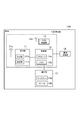
- FIG. 2 is a diagram showing a configuration of a roadside machine 200 according to an embodiment.
- the roadside unit 200 includes a communication unit 21, a control unit 22, an interface 23, and a GNSS (Global Navigation Satellite System) receiver 24.
- GNSS Global Navigation Satellite System
- the communication unit 21 performs road-to-vehicle communication with the on-board unit 150 and road-to-road communication with another roadside unit 200 (adjacent roadside unit).
- the communication unit 21 has an antenna 21a, a reception unit 21b, and a transmission unit 21c, and performs wireless communication via the antenna 21a.
- the antenna 21a may be an omnidirectional antenna or a directional antenna having directivity.
- the antenna 21a may be an adaptive array antenna whose directivity can be dynamically changed.
- the receiving unit 21b converts the radio signal received by the antenna 21a into received data and outputs the radio signal to the control unit 22.
- the transmission unit 21c converts the transmission data output by the control unit 22 into a wireless signal and transmits it from the antenna 21a.
- the wireless communication method of the communication unit 21 may be a method compliant with the T109 standard of ARIB (Association of Radio Industries and Businesses), or 3GPP (Third Generation Partnership Project) V2X (Vehicle). It may be a method compliant with the wireless LAN (Local Area Network) standard such as the IEEE (Institute of Electrical and Electronics Engineers) 802.11 series.
- the communication unit 21 may be configured to be compatible with two or more of these communication standards.
- an example in which the communication unit 21 performs wireless communication using a method compliant with the ARIB T109 standard will be mainly described.
- the control unit 22 controls various functions of the roadside machine 200.
- the control unit 22 has at least one memory 22b and at least one processor 22a electrically connected to the memory 22b.
- the memory 22b includes a volatile memory and a non-volatile memory, and stores information used for processing in the processor 22a and a program executed by the processor 22a.
- the memory 22b corresponds to a storage unit.
- the processor 22a performs various processes by executing the program stored in the memory 22b.
- the interface 23 is connected to the server 400 via a wired line and / or a wireless line.
- the interface 23 may be electrically connected to the traffic signal 300.
- the GNSS receiver 24 receives a GNSS signal from the GNSS satellite via the antenna 24a.
- the GNSS receiver 24 includes, for example, GPS (Global Positioning System), GLONASS (Global Navigation Satellite System), IRNSS (Indian Regional Navigation Satellite System), IRNSS (Indian Regional Navigation Satellite System), IRNSS (Indian Regional Navigation Satellite System), IRNSS (Indian Regional Navigation Satellite System), IRNSS (Indian Regional Navigation Satellite System). ..
- GPS Global Positioning System
- GLONASS Global Navigation Satellite System
- IRNSS Indian Regional Navigation Satellite System
- IRNSS Indian Regional Navigation Satellite System
- IRNSS Indian Regional Navigation Satellite System
- IRNSS Indian Regional Navigation Satellite System
- IRNSS Indian Regional Navigation Satellite System
- FIG. 3 is a diagram showing a configuration of a vehicle 100 according to an embodiment.
- the vehicle 100 has a communication unit 11, a GNSS receiver 12, a notification unit 13, a drive control unit 14, and a control unit 15.
- the communication unit 11, the GNSS receiver 12, and the control unit 15 constitute an on-board unit 150.
- the communication unit 11 performs road-to-vehicle communication with the roadside unit 200.
- the communication unit 11 may perform wireless communication (that is, vehicle-to-vehicle communication) with another vehicle 100 (another on-board unit 150).
- the communication unit 11 has an antenna 11a, a reception unit 11b, and a transmission unit 11c, and performs wireless communication via the antenna 11a.
- the receiving unit 11b converts the radio signal received by the antenna 11a into received data and outputs the radio signal to the control unit 15.
- the transmission unit 11c converts the transmission data output by the control unit 15 into a wireless signal and transmits it from the antenna 11a.
- the wireless communication method of the communication unit 11 may be a method compliant with the T109 standard of ARIB, a method compliant with the V2X standard of 3GPP, or a wireless LAN standard compliant with the IEEE802.11 series or the like. It may be the method described above.
- the communication unit 11 may be configured to be compatible with two or more of these communication standards.
- an example in which the communication unit 21 performs wireless communication using a method compliant with the ARIB T109 standard will be mainly described.
- the GNSS receiver 12 receives a GNSS signal from the GNSS satellite via the antenna 12a.
- the GNSS receiver 12 includes, for example, a receiver of at least one GNSS among GPS, GLONASS, IRNSS, COMPASS, and Galileo.
- GPS Global System for Mobile Communications
- IRNSS IRNSS
- COMPASS COMPASS
- Galileo Galileo
- the notification unit 13 notifies the driver of the vehicle 100 of the information under the control of the control unit 15.
- the notification unit 13 has a display 13a for displaying information and a speaker 13b for outputting information by voice.
- the drive control unit 14 controls an engine or motor as a power source, a power transmission mechanism, a brake, and the like.
- the drive control unit 14 may perform operation control of the vehicle 100 in cooperation with the control unit 15.
- the control unit 15 controls various functions in the vehicle 100 (vehicle-mounted device 150).
- the control unit 15 has at least one memory 15b and at least one processor 15a electrically connected to the memory 15b.
- the memory 15b includes a volatile memory and a non-volatile memory, and stores information used for processing in the processor 15a and a program executed by the processor 15a.
- the processor 15a performs various processes by executing the program stored in the memory 15b.
- FIG. 4 is a diagram for explaining the operation of the roadside machine 200 according to the embodiment.
- each roadside unit 200 (roadside units 200A and 200B) manages a timer that determines a transmission cycle in inter-road communication.
- This transmission cycle is variable, and a timer that measures such a variable transmission cycle is called an "N second cycle timer".
- the control unit 22 of each roadside unit 200 controls the communication unit 21 so as to transmit a message of inter-road communication in a transmission cycle of N seconds by managing an N-second cycle timer. Such a transmission cycle of N seconds needs to be the same between the adjacent roadside machines 200.
- an offset time is set for each roadside unit 200 so that the transmission timing (transmission time slot) of the roadside communication does not collide between the adjacent roadside units 200.
- the roadside machine 200A is said to be "0 ms", “300 ms”, and "600 ms".
- a message for inter-road communication is transmitted at each timing (each time slot).
- the roadside machine 200A is said to be "100 ms", “400 ms”, and "700 ms".
- a message for inter-road communication is transmitted at each timing (each time slot).
- the transmission cycles (N seconds) of the roadside communication of each roadside machine 200 do not match, and / or if the current values of the N second cycle timers of each roadside machine 200 do not match, they are close to each other.
- the transmission timing (transmission time slot) of the roadside communication may collide between the roadside units 200. Therefore, interference of road-to-road communication may occur between the roadside units 200. That is, when the transmission cycle of the roadside communication is not synchronized between the adjacent roadside units 200, interference of the roadside communication may occur between the roadside units 200.
- the roadside units 200A and 200B perform inter-road communication, which is wireless communication between the roadside units 200.
- the roadside machine 200A is an example of a first base station
- the roadside machine 200B is an example of a second base station.
- the roadside machine 200A transmits a message having a MAC (Medium Access Control) address field (hereinafter, referred to as "inter-road communication message") by inter-road communication.
- Such an inter-road communication message may be referred to as an inter-road communication packet.
- the roadside unit 200B receives an inter-road communication message from the roadside unit 200A.
- the roadside machine 200B is installed around the roadside machine 200A and is within the reach of radio waves from the roadside machine 200A.
- the roadside unit 200A broadcasts an inter-road communication message.
- the inter-road communication message does not include the destination MAC address or includes a broadcast address as the destination MAC address.
- the MAC address is also called a link address.
- the road-to-road communication message includes an identifier that identifies the roadside machine 200A.
- This identifier is an identifier managed in a layer higher than the MAC layer (for example, an application layer). This identifier is different from the MAC address of the roadside machine 200A.
- the source MAC address field for storing the MAC address of the roadside machine 200A does not necessarily have to exist. Specifically, in the case of inter-road communication by broadcasting, it is less necessary to specify the source of the inter-road communication message. Even when it is necessary to specify the source of the inter-road communication message, the source of the inter-road communication message can be specified by the identifier managed in the upper layer.
- the roadside machine 200A stores information different from the MAC address and used for synchronization between the roadside machines 200 in at least a part of the MAC address field included in the roadside communication message.
- this MAC address field is a source MAC address field that stores the MAC address of the roadside machine 200A.
- the synchronization information is transmitted to the other roadside machine 200 (roadside machine 200B) by using the source MAC address field of the roadside communication message without providing an additional field for the existing roadside communication message format. ) Can be transmitted. That is, the synchronization information can be efficiently transmitted to another roadside machine 200 (roadside machine 200B) while maintaining the format of the roadside communication message defined by the existing standard.
- FIG. 5 is a diagram showing an example of the source MAC address field of the inter-road communication message according to the embodiment.
- the source MAC address field is composed of a total of 6 octets, that is, the 0th octet to the 5th octet.
- 6 octets for example, a total of 2 octets, the 4th octet and the 5th octet, are assigned to the synchronization information. Alternatively, all of these 6 octets may be assigned to the synchronization information.
- the 0th to 3rd octets can be assigned to the source MAC address, but a part of the source MAC address may be missing. ..
- the roadside machine 200A may store the complete source MAC address in the source MAC address field instead of storing the synchronization information in the source MAC address field once every plurality of times.
- the roadside machine 200B can supplement the missing part of the source MAC address received later by using the complete source MAC address received earlier.
- the synchronization information stored in the source MAC address of the inter-road communication message includes timer-related information regarding the N-second cycle timer managed by the roadside machine 200A.
- the roadside machine 200B uses the timer-related information stored in the source MAC address of the roadside communication message to manage the N-second cycle timer managed by the roadside machine 200B by the roadside machine 200A. Can be synchronized with.
- the timer-related information includes at least one of a cycle value (hereinafter referred to as "N value") indicating the transmission cycle (N seconds) of the inter-road communication message and the current value of the N-second cycle timer.
- N value a cycle value
- the timer-related information may further include the offset time of transmission of the inter-road communication message.
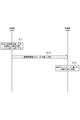
- FIG. 6 is a diagram showing an operation pattern 1 according to an embodiment.
- the roadside machine 200A is started first, and then the roadside machine 200B is started.
- the control unit 22 of the roadside unit 200A determines whether or not the communication unit 21 of the roadside unit 200A has received the roadside communication message.
- the control unit 22 of the roadside machine 200A determines that there is no other roadside machine 200 around the roadside machine 200A, and autonomously determines the N value.
- the N value set here may be, for example, a value notified from the server 400 to the roadside machine 200A.
- FIG. 6 shows an example in which the set N value is 10 seconds.
- step S12 the control unit 22 of the roadside machine 200A controls the communication unit 21 of the roadside machine 200A so as to transmit the inter-road communication message by broadcasting.
- the control unit 22 of the roadside machine 200A controls the communication unit 21 of the roadside machine 200A so that the N value set in step S11 is stored in a part of the source MAC address field of the roadside communication message.
- the communication unit 21 of the roadside unit 200B receives the inter-road communication message from the roadside unit 200A.
- step S13 the control unit 22 of the roadside unit 200B sets the N value of the roadside unit 200B based on the inter-road communication message received by the communication unit 21 of the roadside unit 200B. Specifically, the control unit 22 of the roadside machine 200B matches the N value of the roadside machine 200B with the N value stored in the source MAC address field of the received inter-road communication message. As a result, the N values of the roadside machines 200A and 200B are the same.
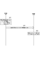
- FIG. 7 is a diagram showing an operation pattern 2 according to one embodiment.
- this operation pattern of the roadside machines 200A and 200B, the roadside machine 200A is started first, and then the roadside machine 200B is started.
- the control unit 22 of the roadside unit 200A determines whether or not the communication unit 21 of the roadside unit 200A has received the roadside communication message.
- the control unit 22 of the roadside unit 200A determines that there is no other roadside unit 200 in the vicinity of the roadside unit 200A, and determines that there is no other roadside unit 200 in the vicinity of the roadside unit 200A. Start timing (counting) autonomously.
- step S22 the control unit 22 of the roadside machine 200A controls the communication unit 21 of the roadside machine 200A so as to transmit the inter-road communication message by broadcasting.
- the control unit 22 of the roadside machine 200A controls the communication unit 21 of the roadside machine 200A so as to store the current value of the N-second cycle timer in a part of the source MAC address field of the inter-road communication message.
- the communication unit 21 of the roadside unit 200B receives the inter-road communication message from the roadside unit 200A.
- FIG. 7 shows an example in which the current value of the N-second cycle timer is 1.2 seconds.
- step S23 the control unit 22 of the roadside unit 200B sets (corrects) the current value of the N-second cycle timer of the roadside unit 200B based on the inter-road communication message received by the communication unit 21 of the roadside unit 200B. Specifically, the control unit 22 of the roadside machine 200B matches the current value of the N-second period timer of the roadside machine 200B with the current value stored in the source MAC address field of the received inter-road communication message. As a result, the current values of the N-second period timers of the roadside machines 200A and 200B are matched.
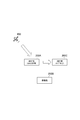
- GNSS synchronization using the absolute time of GNSS There are two types of methods for synchronizing the frame timing between the roadside units 200: GNSS synchronization using the absolute time of GNSS and air synchronization using inter-road communication.
- FIG. 8 is a diagram showing GNSS synchronization according to this modified example. As shown in FIG. 8, each of the roadside machine 200A and the roadside machine 200B performs frame timing synchronization using the GNSS signal received by the GNSS receiver 24 from the GNSS satellite 600. When each roadside unit 200 can receive a GNSS signal, GNSS synchronization is the most reliable and accurate synchronization method.
- FIG. 9 is a diagram showing air synchronization according to this modified example.
- the roadside machine 200A performs frame timing synchronization using the GNSS signal received by the GNSS receiver 24 from the GNSS satellite 600.
- the roadside machine 200C cannot receive the GNSS signal from the GNSS satellite 600 and cannot use the GNSS synchronization. Therefore, the roadside machine 200C receives radio waves from the roadside machine 200A, which is an adjacent roadside machine 200, and performs frame timing synchronization using the reception timing. Since the roadside machine 200C using such air synchronization basically controls the frame timing by the self-propelled clock, it is a synchronization method having lower reliability and accuracy than the GNSS synchronization.
- the roadside machine 200B cannot receive the GNSS signal. Further, the roadside machine 200B is located in the vicinity of the roadside machines 200A and 200C, and can receive an inter-road communication message from each of the roadside machines 200A and 200C.
- the roadside machine 200B sets the roadside machine 200A during GNSS synchronization as the air synchronization target of the roadside machine 200B rather than the roadside machine 200C during air synchronization. That is, it is not preferable that the roadside machine 200B sets the roadside machine 200C during air synchronization as the air synchronization target of the roadside machine 200B.
- the synchronization information stored in the source MAC address of the inter-road communication message transmitted by the roadside unit 200A includes the synchronization type information regarding the synchronization target of the roadside unit 200A.
- the synchronization type information regarding the synchronization target of the roadside machine 200A is information indicating GNSS synchronization.
- the information indicating GNSS synchronization may be information indicating that it is not air synchronization.
- the synchronization information stored in the source MAC address of the inter-road communication message transmitted by the roadside machine 200C includes the synchronization type information regarding the synchronization target of the roadside machine 200C.
- the synchronization type information regarding the synchronization target of the roadside machine 200C is information indicating air synchronization.
- the information indicating air synchronization may be information indicating that it is not GNSS synchronization.
- FIG. 10 is a diagram showing an operation pattern 1 according to this modified example.
- the roadside machines 200A, 200B, and 200C are started first, and then the roadside machine 200B is started. Further, it is assumed that the roadside units 200B and 200C cannot receive the GNSS signal (that is, GNSS synchronization is not possible).
- step S31 the control unit 22 of the roadside machine 200C controls the communication unit 21 of the roadside machine 200C so as to transmit the inter-road communication message by broadcasting.
- the control unit 22 of the roadside machine 200C stores the synchronization type information indicating that the roadside machine 200C is in air synchronization in a part of the source MAC address field of the roadside communication message. It controls the communication unit 21 of 200C.
- the communication unit 21 of the roadside unit 200B receives the inter-road communication message from the roadside unit 200A.
- step S32 the control unit 22 of the roadside machine 200A controls the communication unit 21 of the roadside machine 200A so as to broadcast the inter-road communication message.
- the control unit 22 of the roadside machine 200A uses a part of the source MAC address field of the roadside communication message to provide synchronization type information indicating that the roadside machine 200A is in GNSS synchronization (not in air synchronization).
- the communication unit 21 of the roadside machine 200A is controlled so as to be stored in.
- the communication unit 21 of the roadside unit 200B receives the inter-road communication message from the roadside unit 200A.
- step S33 the control unit 22 of the roadside machine 200B sets the air synchronization target of the roadside machine 200B based on the synchronization type information stored in the MAC address field of the roadside communication message received in steps S31 and S32.
- the control unit 22 of the roadside unit 200B uses the roadside unit 200C as the roadside unit because the synchronization type information stored in the MAC address field of the roadside communication message received from the roadside unit 200C is information indicating air synchronization. It is determined not to be set as the synchronization target of the 200B (that is, excluded from the synchronization target of the roadside machine 200B).
- the control unit 22 of the roadside machine 200A uses the roadside machine 200A as the roadside machine because the synchronization type information stored in the MAC address field of the roadside communication message received from the roadside machine 200A is the information indicating GNSS synchronization. It is decided to set it as an air synchronization target of 200B.
- FIG. 11 is a diagram showing an operation pattern 2 according to this modified example.
- the roadside machines 200A, 200B, and 200C are started first, and then the roadside machine 200B is started. Further, it is assumed that the roadside units 200B and 200C cannot receive the GNSS signal (that is, GNSS synchronization is not possible).
- step S41 the control unit 22 of the roadside machine 200C controls the communication unit 21 of the roadside machine 200C so as to transmit the inter-road communication message by broadcasting.
- the control unit 22 of the roadside machine 200C stores the synchronization type information indicating that the roadside machine 200C is in air synchronization in a part of the source MAC address field of the roadside communication message. It controls the communication unit 21 of 200C.
- the communication unit 21 of the roadside unit 200B receives the inter-road communication message from the roadside unit 200A.
- step S42 the control unit 22 of the roadside machine 200A controls the communication unit 21 of the roadside machine 200A so as to broadcast an inter-road communication message.
- the control unit 22 of the roadside machine 200A uses a part of the source MAC address field of the roadside communication message to provide synchronization type information indicating that the roadside machine 200A is in GNSS synchronization (not in air synchronization).
- the communication unit 21 of the roadside machine 200A is controlled so as to be stored in. However, the roadside machine 200A is far from the roadside machine 200B, and the inter-road communication message from the roadside machine 200A is not received by the roadside machine 200B.
- step S43 the control unit 22 of the roadside machine 200B sets the air synchronization target of the roadside machine 200B based on the synchronization type information stored in the MAC address field of the roadside communication message received from the roadside machine 200C in step S41. do.
- the control unit 22 of the roadside unit 200B uses the roadside unit 200C as the roadside unit because the synchronization type information stored in the MAC address field of the roadside communication message received from the roadside unit 200C is information indicating air synchronization. It is determined not to be set as the synchronization target of the 200B (that is, excluded from the synchronization target of the roadside machine 200B).
- the control unit 22 of the roadside machine 200B controls the frame timing by the self-propelled clock.
- the control unit 22 of the roadside machine 200B may determine that the operation of the roadside machine 200B is to be stopped and stop the transmission of radio waves.
- the communication system is the transportation communication system 1
- the communication system may be another communication system such as a cellular communication system.
- the server 400 may be an edge server arranged near the roadside machine 200.
- Such an edge server may be regarded as a part of the roadside machine 200.
- the edge server is provided between the roadside machine 200 and the Internet, and controls roads in an area limited to a predetermined range.
- the edge server may be connected to the roadside unit 200 via a LAN (Local Area Network) without going through a WAN (Wide Area Network).
- LAN Local Area Network
- WAN Wide Area Network
- a program for causing a computer to execute each process according to the above-described embodiment may be provided.
- the program may be recorded on a computer-readable medium.
- Computer-readable media allow you to install programs on your computer.
- the computer-readable medium on which the program is recorded may be a non-transient recording medium.
- the non-transient recording medium is not particularly limited, but may be, for example, a recording medium such as a CD-ROM or a DVD-ROM.
Landscapes
- Engineering & Computer Science (AREA)
- Computer Networks & Wireless Communication (AREA)
- Signal Processing (AREA)
- Mobile Radio Communication Systems (AREA)
- Traffic Control Systems (AREA)
Priority Applications (2)
| Application Number | Priority Date | Filing Date | Title |
|---|---|---|---|
| JP2022517013A JP7377959B2 (ja) | 2020-04-24 | 2021-04-15 | 通信システム、基地局、及び通信制御方法 |
| US18/047,929 US20230063740A1 (en) | 2020-04-24 | 2022-10-19 | Communication system, base station, and communication control method |
Applications Claiming Priority (2)
| Application Number | Priority Date | Filing Date | Title |
|---|---|---|---|
| JP2020-077777 | 2020-04-24 | ||
| JP2020077777 | 2020-04-24 |
Related Child Applications (1)
| Application Number | Title | Priority Date | Filing Date |
|---|---|---|---|
| US18/047,929 Continuation US20230063740A1 (en) | 2020-04-24 | 2022-10-19 | Communication system, base station, and communication control method |
Publications (1)
| Publication Number | Publication Date |
|---|---|
| WO2021215350A1 true WO2021215350A1 (ja) | 2021-10-28 |
Family
ID=78269223
Family Applications (1)
| Application Number | Title | Priority Date | Filing Date |
|---|---|---|---|
| PCT/JP2021/015611 Ceased WO2021215350A1 (ja) | 2020-04-24 | 2021-04-15 | 通信システム、基地局、及び通信制御方法 |
Country Status (3)
| Country | Link |
|---|---|
| US (1) | US20230063740A1 (https=) |
| JP (1) | JP7377959B2 (https=) |
| WO (1) | WO2021215350A1 (https=) |
Citations (2)
| Publication number | Priority date | Publication date | Assignee | Title |
|---|---|---|---|---|
| JP2017534215A (ja) * | 2014-11-11 | 2017-11-16 | クゥアルコム・インコーポレイテッドQualcomm Incorporated | ネイバーアウェアネットワーク(nan)中のアクセスポイント間での近隣情報の通信 |
| US20180020410A1 (en) * | 2016-07-18 | 2018-01-18 | Neuromeka | Power saving for wireless local area network |
-
2021
- 2021-04-15 WO PCT/JP2021/015611 patent/WO2021215350A1/ja not_active Ceased
- 2021-04-15 JP JP2022517013A patent/JP7377959B2/ja active Active
-
2022
- 2022-10-19 US US18/047,929 patent/US20230063740A1/en not_active Abandoned
Patent Citations (2)
| Publication number | Priority date | Publication date | Assignee | Title |
|---|---|---|---|---|
| JP2017534215A (ja) * | 2014-11-11 | 2017-11-16 | クゥアルコム・インコーポレイテッドQualcomm Incorporated | ネイバーアウェアネットワーク(nan)中のアクセスポイント間での近隣情報の通信 |
| US20180020410A1 (en) * | 2016-07-18 | 2018-01-18 | Neuromeka | Power saving for wireless local area network |
Also Published As
| Publication number | Publication date |
|---|---|
| JP7377959B2 (ja) | 2023-11-10 |
| JPWO2021215350A1 (https=) | 2021-10-28 |
| US20230063740A1 (en) | 2023-03-02 |
Similar Documents
| Publication | Publication Date | Title |
|---|---|---|
| US20230292239A1 (en) | Method and device for sidelink communication based on parameters | |
| US11215993B2 (en) | Method and device for data sharing using MEC server in autonomous driving system | |
| US10952043B2 (en) | Vehicle to everything (V2X) communication method and system | |
| US10299088B2 (en) | User terminal, RSU, method and program | |
| AU2017214894B2 (en) | Cooperative vehicle-to-anything (V2X) communication from terminal device to vehicle-mounted device with support from base station or road side unit (RSU) | |
| JP6696192B2 (ja) | 通信装置および通信方法 | |
| CN108028710B (zh) | 传输通信消息的装置和方法 | |
| US9340154B2 (en) | Collision avoidance in vehicular networks | |
| US20150312883A1 (en) | Method for transmitting data from communication device for providing vehicle infotainment service and system using the same | |
| WO2013008448A1 (ja) | 端末装置および通信システム | |
| EP3829201B1 (en) | Method, device, and system for transmitting system information between internet-of-vehicles devices | |
| US10700798B1 (en) | System and method to receive and deliver audio content | |
| JP7377959B2 (ja) | 通信システム、基地局、及び通信制御方法 | |
| KR20200130178A (ko) | 무선 통신에서 도로 유저를 주소 지정하기 위한 개념 | |
| JP2021021653A (ja) | 交通通信システム、基地局、移動局、及び車両 | |
| JP7503020B2 (ja) | 無線路側機、交通通信システム、及び交通通信方法 | |
| WO2022249930A1 (ja) | 路側機、制御方法、及び無線通信システム | |
| US20230300568A1 (en) | User equipment coordinated positioning | |
| JP7228432B2 (ja) | 基地局及びその制御方法 | |
| JP7150041B2 (ja) | 基地局、管理装置、及び方法 | |
| US20200177325A1 (en) | V2x communication device and geonetworking transmission method | |
| WO2022220195A1 (ja) | 無線路側機、車載通信機、車両、交通通信システム、及び交通通信方法 |
Legal Events
| Date | Code | Title | Description |
|---|---|---|---|
| 121 | Ep: the epo has been informed by wipo that ep was designated in this application |
Ref document number: 21793194 Country of ref document: EP Kind code of ref document: A1 |
|
| ENP | Entry into the national phase |
Ref document number: 2022517013 Country of ref document: JP Kind code of ref document: A |
|
| NENP | Non-entry into the national phase |
Ref country code: DE |
|
| 122 | Ep: pct application non-entry in european phase |
Ref document number: 21793194 Country of ref document: EP Kind code of ref document: A1 |