WO2021210676A1 - 医療画像処理装置、内視鏡システム及び医療画像処理装置の作動方法並びに医療画像処理装置用プログラム - Google Patents
医療画像処理装置、内視鏡システム及び医療画像処理装置の作動方法並びに医療画像処理装置用プログラム Download PDFInfo
- Publication number
- WO2021210676A1 WO2021210676A1 PCT/JP2021/015712 JP2021015712W WO2021210676A1 WO 2021210676 A1 WO2021210676 A1 WO 2021210676A1 JP 2021015712 W JP2021015712 W JP 2021015712W WO 2021210676 A1 WO2021210676 A1 WO 2021210676A1
- Authority
- WO
- WIPO (PCT)
- Prior art keywords
- highlighting
- medical image
- setting value
- image
- interest
- Prior art date
- Legal status (The legal status is an assumption and is not a legal conclusion. Google has not performed a legal analysis and makes no representation as to the accuracy of the status listed.)
- Ceased
Links
Images


Classifications
-
- G—PHYSICS
- G16—INFORMATION AND COMMUNICATION TECHNOLOGY [ICT] SPECIALLY ADAPTED FOR SPECIFIC APPLICATION FIELDS
- G16H—HEALTHCARE INFORMATICS, i.e. INFORMATION AND COMMUNICATION TECHNOLOGY [ICT] SPECIALLY ADAPTED FOR THE HANDLING OR PROCESSING OF MEDICAL OR HEALTHCARE DATA
- G16H30/00—ICT specially adapted for the handling or processing of medical images
- G16H30/20—ICT specially adapted for the handling or processing of medical images for handling medical images, e.g. DICOM, HL7 or PACS
-
- G—PHYSICS
- G06—COMPUTING OR CALCULATING; COUNTING
- G06V—IMAGE OR VIDEO RECOGNITION OR UNDERSTANDING
- G06V10/00—Arrangements for image or video recognition or understanding
- G06V10/20—Image preprocessing
- G06V10/25—Determination of region of interest [ROI] or a volume of interest [VOI]
-
- A—HUMAN NECESSITIES
- A61—MEDICAL OR VETERINARY SCIENCE; HYGIENE
- A61B—DIAGNOSIS; SURGERY; IDENTIFICATION
- A61B1/00—Instruments for performing medical examinations of the interior of cavities or tubes of the body by visual or photographical inspection, e.g. endoscopes; Illuminating arrangements therefor
- A61B1/04—Instruments for performing medical examinations of the interior of cavities or tubes of the body by visual or photographical inspection, e.g. endoscopes; Illuminating arrangements therefor combined with photographic or television appliances
- A61B1/045—Control thereof
-
- A—HUMAN NECESSITIES
- A61—MEDICAL OR VETERINARY SCIENCE; HYGIENE
- A61B—DIAGNOSIS; SURGERY; IDENTIFICATION
- A61B8/00—Diagnosis using ultrasonic, sonic or infrasonic waves
- A61B8/13—Tomography
- A61B8/14—Echo-tomography
-
- G—PHYSICS
- G06—COMPUTING OR CALCULATING; COUNTING
- G06V—IMAGE OR VIDEO RECOGNITION OR UNDERSTANDING
- G06V10/00—Arrangements for image or video recognition or understanding
- G06V10/10—Image acquisition
- G06V10/12—Details of acquisition arrangements; Constructional details thereof
- G06V10/14—Optical characteristics of the device performing the acquisition or on the illumination arrangements
- G06V10/143—Sensing or illuminating at different wavelengths
-
- G—PHYSICS
- G16—INFORMATION AND COMMUNICATION TECHNOLOGY [ICT] SPECIALLY ADAPTED FOR SPECIFIC APPLICATION FIELDS
- G16H—HEALTHCARE INFORMATICS, i.e. INFORMATION AND COMMUNICATION TECHNOLOGY [ICT] SPECIALLY ADAPTED FOR THE HANDLING OR PROCESSING OF MEDICAL OR HEALTHCARE DATA
- G16H20/00—ICT specially adapted for therapies or health-improving plans, e.g. for handling prescriptions, for steering therapy or for monitoring patient compliance
- G16H20/40—ICT specially adapted for therapies or health-improving plans, e.g. for handling prescriptions, for steering therapy or for monitoring patient compliance relating to mechanical, radiation or invasive therapies, e.g. surgery, laser therapy, dialysis or acupuncture
-
- G—PHYSICS
- G16—INFORMATION AND COMMUNICATION TECHNOLOGY [ICT] SPECIALLY ADAPTED FOR SPECIFIC APPLICATION FIELDS
- G16H—HEALTHCARE INFORMATICS, i.e. INFORMATION AND COMMUNICATION TECHNOLOGY [ICT] SPECIALLY ADAPTED FOR THE HANDLING OR PROCESSING OF MEDICAL OR HEALTHCARE DATA
- G16H30/00—ICT specially adapted for the handling or processing of medical images
- G16H30/40—ICT specially adapted for the handling or processing of medical images for processing medical images, e.g. editing
-
- G—PHYSICS
- G16—INFORMATION AND COMMUNICATION TECHNOLOGY [ICT] SPECIALLY ADAPTED FOR SPECIFIC APPLICATION FIELDS
- G16H—HEALTHCARE INFORMATICS, i.e. INFORMATION AND COMMUNICATION TECHNOLOGY [ICT] SPECIALLY ADAPTED FOR THE HANDLING OR PROCESSING OF MEDICAL OR HEALTHCARE DATA
- G16H50/00—ICT specially adapted for medical diagnosis, medical simulation or medical data mining; ICT specially adapted for detecting, monitoring or modelling epidemics or pandemics
- G16H50/20—ICT specially adapted for medical diagnosis, medical simulation or medical data mining; ICT specially adapted for detecting, monitoring or modelling epidemics or pandemics for computer-aided diagnosis, e.g. based on medical expert systems
-
- G—PHYSICS
- G06—COMPUTING OR CALCULATING; COUNTING
- G06V—IMAGE OR VIDEO RECOGNITION OR UNDERSTANDING
- G06V2201/00—Indexing scheme relating to image or video recognition or understanding
- G06V2201/03—Recognition of patterns in medical or anatomical images
Definitions
- the present invention relates to a medical image processing device for detecting a region of interest such as a lesion, an operation method of an endoscopic system and a medical image processing device, and a program for the medical image processing device.
- medical images such as endoscopic images, X-ray images, CT (Computed Tomography) images, and MR (Magnetic Resonanse) images are used to diagnose the patient's medical condition and perform diagnostic imaging such as follow-up. ing. Based on such diagnostic imaging, doctors and the like make decisions on treatment policies.
- Patent Documents 1 and 2 describe a medical image processing apparatus that performs image processing based on the detection information when a region of interest such as a lesion is detected from a medical image.
- diagnostic imaging using such a medical image processing device it is common to detect a region of interest from a medical image in real time and display a medical image on which a highlight that emphasizes the region of interest is superimposed on a monitor in real time. ..
- Patent Documents 1 and 2 When the medical image processing apparatus described in Patent Documents 1 and 2 is used for image diagnosis, when displaying a medical image in which highlighting of a region of interest is superimposed in real time, the highlighting is performed so as not to interfere with the diagnosis of a doctor. It is important not to stand out too much. On the other hand, when medical images are used for viewing still images, reports, presentation materials, etc. other than diagnostic imaging, highlighting different from that at the time of diagnostic imaging may be required.
- the highlighting when displaying in real time at the time of image diagnosis can be set, but the medical image in which the area of interest is highlighted in real time is saved. No consideration is given to highlighting when displaying afterwards.
- the highlighting will not be noticeable when the medical image is displayed in still image viewing, reports, presentation materials, etc., so the area of interest will be in the medical image. The doctor may not be aware of something.
- the present invention relates to a medical image processing device, an endoscopic system, and a medical image processing device that can display the highlighting of a region of interest with different settings when the medical image displayed at the time of image diagnosis is subsequently displayed. It is an object of the present invention to provide an operation method and a program for a medical image processing apparatus.
- the present invention is a medical image processing apparatus including a processor, in which the processor acquires a medical image, detects a region of interest in the medical image, and superimposes a highlighting highlighting the detected region of interest on the medical image.
- the first highlighting setting value is the shape of the highlighting, which is displayed on the display screen, accepts the user input information by the user's input operation, and emphasizes the area of interest when displayed on the display screen by the user input information.
- the setting is changed to a second emphasis setting value that is different from the above, and the medical image is saved with the highlight information including the second emphasis setting value attached.
- the processor changes the setting from the first emphasis setting value to the second emphasis setting value, it is preferable to change the thickness of the frame shape line surrounding the area of interest as the shape change of the highlighting.
- the processor changes the setting from the first emphasis setting value to the second emphasis setting value, it is preferable to change the number of frame-shaped lines surrounding the area of interest as a change in the shape of the highlighting. Further, when the processor changes the setting to the second emphasis setting value, the frame shape may be formed from a plurality of lines having different colors from each other.
- the highlighting by the second emphasis setting value has a higher emphasis than the highlighting by the first emphasis setting value.
- the processor changes the setting from the first emphasis setting value to the second emphasis setting value in one or a plurality of steps.
- the processor does not accept the user input information, it is preferable that the setting is not changed from the first emphasis setting value and the medical image is saved with the highlight information including the first emphasis setting value.
- the processor accepts user input information by any input operation of a keyboard, a press detection device, a voice input device, or a touch panel input device.
- the medical image is an endoscopic image captured by an endoscope, and it is preferable that the processor accepts user input information by inputting an operation button provided on the endoscope.
- the area of interest is the lesion
- the highlighted information includes the location information of the lesion in the medical image, the size of the lesion, whether it is malignant or benign, the degree of progression of the lesion, the presence or absence of treatment, the findings, and the lesion. It is preferable that it relates to any of the site or organ to be treated and patient information.
- the endoscope system of the present invention includes a light source device, an endoscope, a processor, and a monitor, and the processor acquires a medical image, detects a region of interest in the medical image, and detects the region of interest.
- the first highlighting is to superimpose the highlighting on the medical image and display it on the monitor, accept the user input information by the user's input operation, and emphasize the area of interest when displaying on the display screen by the user input information.
- the setting is changed to a second highlighting setting value whose highlighting shape is different from that of the degree setting value, and the medical image is saved with the highlighting information including the second highlighting setting value attached.
- the light source device emits illumination light for illuminating the observation target.
- the endoscope has an imaging sensor that captures an observation object illuminated by illumination light.
- the monitor displays a medical image obtained by signal-processing the image signal output by the image sensor.
- a step of acquiring a medical image, a step of detecting a region of interest in the medical image, and a highlighting highlighting the detected region of interest are superimposed and displayed on the medical image.
- the step of displaying on the screen, the step of accepting the user input information by the user's input operation, and the first emphasis setting value that emphasizes the area of interest when displaying on the display screen by the user input information are emphasized. It includes a step of changing the setting to a second emphasis setting value having a different display shape, and a step of attaching and saving the highlighting information including the second emphasis setting value to the medical image.
- the medical image processing device program of the present invention has a function of acquiring a medical image and acquiring a medical image on a computer in a medical image processing device program installed in a medical image processing device that performs image processing on the medical image.
- a function to detect the area of interest in the medical image a function to superimpose the highlighted area to emphasize the detected area on the medical image and display it on the display screen, and a function to accept user input information by the user's input operation.
- With the function of changing the setting to the second emphasis setting value which has a different highlighting shape from the first emphasis setting value that emphasizes the area of interest when displayed on the display screen, based on the user input information.
- a function of attaching and saving highlighting information including a second highlighting degree setting value to a medical image is realized.
- the highlighting of the area of interest can be displayed with different settings.
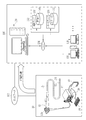
- the endoscope system 10 includes an endoscope 12, a light source device 14, a processor device 16, a monitor 18, and a console 19.
- the endoscope 12 is optically connected to the light source device 14 and electrically connected to the processor device 16.
- the endoscope 12 has an insertion portion 12a to be inserted into the subject, an operation portion 12b provided at the base end portion of the insertion portion 12a, and a curved portion 12c and a tip portion 12d provided on the tip end side of the insertion portion 12a. doing.
- the angle knob 13a of the operating portion 12b By operating the angle knob 13a of the operating portion 12b, the curved portion 12c bends. By this bending operation, the tip portion 12d is directed in a desired direction.
- the operation unit 12b is provided with a freeze switch 13b used for still image acquisition operation, a mode switching unit 13c used for observation mode switching operation, and a zoom operation unit 13d used for zoom magnification changing operation. ing.
- the freeze switch 13b can perform a freeze operation for displaying a still image to be observed on the monitor 18 and a release operation for storing the still image in the storage.
- the freeze switch 13b When the user operates the freeze switch 13b, the still image to be observed is frozen and displayed on the monitor 18, and an alert sound (for example, "pee") indicating that the still image is acquired is emitted. Then, the image storage instruction is output to the image storage control unit 55 or the like, and the still image of the endoscopic image obtained before and after the operation timing of the freeze switch 13b is sent to the image storage unit 56 (see FIG. 2) in the processor device 16. It will be saved.
- an alert sound for example, "pee”
- the illumination light for the attention area detection mode is emitted.
- normal light is emitted as the illumination light for the region of interest detection mode, but special light may be emitted.
- the processor device 16 is electrically connected to the monitor 18 and the console 19.
- the monitor 18 outputs and displays an image to be observed, information incidental to the image, and the like.
- the console 19 functions as a user interface that accepts input operations such as designation of a region of interest (ROI: RegionOfInterest) and function settings.
- ROI region of interest
- the light source unit 20 includes a V-LED (VioletLightEmittingDiode) 20a, a B-LED (BlueLightEmittingDiode) 20b, a G-LED (GreenLightEmittingDiode) 20c, and an R-LED (Red). It has a 4-color LED of LightEmittingDiode) 20d and a wavelength cut filter 23. As shown in FIG. 3, the V-LED 20a emits purple light V having a wavelength band of 380 nm to 420 nm.
- the B-LED20b emits blue light B having a wavelength band of 420 nm to 500 nm.
- the blue light B emitted from the B-LED 23b at least the wavelength side longer than the peak wavelength of 450 nm is cut by the wavelength cut filter 23.
- the blue light Bx after passing through the wavelength cut filter 23 is in the wavelength range of 420 to 460 nm.
- the light in the wavelength region longer than 460 nm is cut because the light in the wavelength region longer than 460 nm reduces the vascular contrast of the blood vessel to be observed. Because there is.
- the wavelength cut filter 23 may dimming the light in the wavelength region longer than 460 nm instead of cutting the light in the wavelength region longer than 460 nm.
- the light source control unit 22 adjusts the emission timing, emission period, light amount, and spectral spectrum of the illumination light by independently controlling the lighting and extinguishing of the LEDs 20a to 20d and the amount of light emitted at the time of lighting.
- the control of turning on and off in the light source control unit 22 is different for each observation mode.
- the reference brightness can be set by the brightness setting unit of the light source device 14, the console 19, or the like.
- the light source control unit 22 lights all the V-LED20a, B-LED20b, G-LED20c, and R-LED20d.
- the peak of the light intensity of the blue light Bx is the purple light V, the green light G.
- red light R are set to be larger than the peak of any of the light intensities.
- the multicolored light for the normal mode or the attention region detection mode including the purple light V, the blue light Bx, the green light G, and the red light R is usually emitted from the light source device 14. As light, is emitted. Normal light is almost white because it has a certain intensity or more from the blue band to the red band.
- the light source control unit 22 lights all the V-LED20a, B-LED20b, G-LED20c, and R-LED20d.
- the light intensity ratio Ls between the purple light V, the blue light B, the green light G, and the red light R has a peak of the light intensity of the purple light V, which is the blue light Bx and the green light G.
- red light R are set to be larger than the peak of any of the light intensities.
- the peaks of the light intensities of the green light G and the red light R are set to be smaller than the peaks of the light intensities of the purple light V and the blue light Bx.
- the light source device 14 emits multicolored light for the special mode including purple light V, blue light Bx, green light G, and red light R as special light.
- the special light is bluish because the proportion of purple light V is large.
- the special light does not have to include light of all four colors, and may include light from at least one of the four color LEDs 20a to 20d. Further, the special light preferably has a main wavelength range of 450 nm or less, for example, a peak wavelength or a center wavelength.
- the illumination light emitted by the light source unit 20 is incident on the light guide 24 inserted into the insertion unit 12a via an optical path coupling portion (not shown) formed by a mirror, a lens, or the like.
- the light guide 24 is built in the endoscope 12 and the universal cord, and propagates the illumination light to the tip portion 12d of the endoscope 12.
- the universal cord is a cord that connects the endoscope 12, the light source device 14, and the processor device 16.
- a multimode fiber can be used as the light guide 24.
- a fine fiber cable having a core diameter of 105 ⁇ m, a clad diameter of 125 ⁇ m, and a diameter of ⁇ 0.3 mm to ⁇ 0.5 mm including a protective layer serving as an outer skin can be used for the light guide 24.
- the illumination optical system 30a and an imaging optical system 30b are provided at the tip portion 12d of the endoscope 12.
- the illumination optical system 30a has an illumination lens 32.
- the observation target is illuminated by the illumination light propagating through the illumination lens 32 and propagating through the light guide 24.
- the imaging optical system 30b includes an objective lens 34, a magnifying optical system 36, and an imaging sensor 38 (corresponding to the “imaging unit” of the present invention).
- Various types of light such as reflected light, scattered light, and fluorescence from the observation target are incident on the image pickup sensor 38 through the objective lens 34 and the magnifying optical system 36. As a result, an image to be observed is formed on the image sensor 38.
- the image sensor 38 is a color image sensor that captures an observation target irradiated with illumination light.
- Each pixel of the image sensor 38 is provided with any one of an R (red) color filter, a G (green) color filter, and a B (blue) color filter.
- the image pickup sensor 38 receives purple to blue light from the B pixel provided with the B color filter, receives green light from the G pixel provided with the G color filter, and is provided with the R color filter.
- the existing R pixel receives red light.
- the image signals of each RGB color are output from the pixels of each color.
- the image sensor 38 transmits the output image signal to the CDS circuit 40.
- the image sensor 38 In the normal mode or the region of interest detection mode, the image sensor 38 outputs a Bc image signal from the B pixel and outputs a Gc image signal from the G pixel by imaging an observation target illuminated with normal light, and R The Rc image signal is output from the pixels. Further, in the special mode, the image sensor 38 outputs a Bs image signal from the B pixel, outputs a Gs image signal from the G pixel, and Rs from the R pixel by imaging the observation target illuminated with the special light. Output the image signal.
- the CDS circuit 40 performs correlated double sampling (CDS: Correlated Double Sampling) on the analog image signal received from the image sensor 38.
- CDS Correlated Double Sampling
- the image signal that has passed through the CDS circuit 40 is input to the AGC circuit 42.
- the AGC circuit 40 performs automatic gain control (AGC: Automatic Gain Control) on the input image signal.
- a / D (Analog to Digital) conversion circuit 44 converts an analog image signal that has passed through the AGC circuit 42 into a digital image signal.
- the A / D conversion circuit 44 inputs the digital image signal after the A / D conversion to the processor device 16.
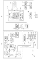
- the processor device 16 includes an image signal acquisition unit 50, a DSP (Digital Signal Processor) 51, a noise reduction unit 52, an image processing unit 53, a display control unit 54, and the like. It includes an image storage control unit 55, an image storage unit 56, and a user input reception unit 57.
- DSP Digital Signal Processor
- the image signal acquisition unit 50 acquires a digital image signal corresponding to the observation mode from the endoscope 12.
- the Bc image signal, the Gc image signal, and the Rc image signal are acquired.
- the Bs image signal, the Gs image signal, and the Rs image signal are acquired.
- one frame of Bc image signal, Gc image signal, and Rc image signal is acquired when the normal light is illuminated, and one frame of Bs image signal, Gs image signal, is acquired when the special light is illuminated. Acquire the Rs image signal.
- the DSP 51 performs various signal processing such as defect correction processing, offset processing, gain correction processing for DSP, linear matrix processing, gamma conversion processing, and demosaic processing on the image signal acquired by the image signal acquisition unit 50.
- the defect correction process corrects the signal of the defective pixel of the image sensor 38.
- the offset processing removes the dark current component from the defect-corrected image signal and sets an accurate zero level.
- the DSP gain correction process adjusts the signal level by multiplying the offset-processed image signal by a specific DSP gain.
- the linear matrix processing enhances the color reproducibility of the image signal that has been gain-corrected for DSP.
- the gamma conversion process adjusts the brightness and saturation of the image signal processed by the linear matrix.
- the gamma-converted image signal is subjected to demosaic processing (also referred to as isotropic processing or simultaneous processing) to generate a signal of a color lacking in each pixel by interpolation. By this demosaic processing, all the pixels have RGB signals of each color.
- the noise reduction unit 52 reduces noise by, for example, performing noise reduction processing by a moving average method, a median filter method, or the like on an image signal that has undergone demosaic processing or the like by DSP 51.
- the image signal after noise reduction is input to the image processing unit 53.
- the image processing unit 53 includes a normal mode image processing unit 58, a special mode image processing unit 59, and a region of interest detection mode image processing unit 60.
- the normal mode image processing unit 58 operates when the normal mode is set, and performs color conversion processing, color enhancement processing, and structure enhancement processing on the received Bc image signal, Gc image signal, and Rc image signal. conduct.
- the RGB image signal is subjected to color conversion processing by 3 ⁇ 3 matrix processing, gradation conversion processing, three-dimensional LUT (Look Up Table) processing, or the like.
- the color enhancement process is performed on the RGB image signal that has undergone the color conversion process.
- the structure enhancement process is a process for emphasizing the structure of the observation target, and is performed on the RGB image signal after the color enhancement process.
- a normal image can be obtained by performing various image processing and the like as described above. Since the normal image is an image obtained based on normal light in which purple light V, blue light Bx, green light G, and red light R are emitted in a well-balanced manner, it is an image having a natural hue.
- the normal image is input to the display control unit 54.
- the special mode image processing unit 59 operates when the special mode is set.
- the special mode image processing unit 59 performs color conversion processing, color enhancement processing, and structure enhancement processing on the received Bs image signal, Gs image signal, and Rs image signal.
- the processing contents of the color conversion processing, the color enhancement processing, and the structure enhancement processing are the same as those of the normal mode image processing unit 58.
- a special image can be obtained by performing various image processing as described above.
- the special image is an image obtained based on special light in which purple light V, which has a high absorption coefficient of hemoglobin in blood vessels, emits a larger amount of light than blue light Bx, green light G, and red light R of other colors. Therefore, the resolution of the vascular structure and the ductal structure is higher than that of other structures.
- the special image is input to the display control unit 54.
- the attention area detection mode image processing unit 60 operates when the attention area detection mode is set. As shown in FIG. 6, the attention area detection mode image processing unit 60 includes a detection image processing unit 70, an attention area detection unit 71, and an emphasis setting unit 72.
- the detection image processing unit 70 sequentially acquires the endoscopic image 75 from the received Bc image signal, Gc image signal, and Rc image signal by the same image processing as the normal mode image processing unit 58 such as color conversion processing. ..
- the attention area detection unit 71 analyzes the endoscopic image 75 and performs the attention area detection process for detecting the attention area in the observation target.
- the region of interest detection unit 71 detects a lesion (for example, a tumor, inflammation, etc.) in the observation target as the region of interest.
- the region of interest detection unit 71 first divides the endoscopic image 75 into a plurality of small regions, for example, a square region for several pixels. Next, the image feature amount is calculated from the divided endoscopic image 75. Subsequently, based on the calculated feature amount, whether or not each small region is a lesion is recognized and processed.
- a machine learning algorithm such as a convolutional neural network or deep learning is preferable.
- the feature amount calculated from the endoscopic image 75 by the region of interest detection unit 71 is preferably a value obtained from the shape and color of a predetermined portion in the observation target or those shapes and colors.
- a value obtained from the shape and color of a predetermined portion in the observation target or those shapes and colors is preferable.
- the value is at least one of the length, the degree of tortuosity of the blood vessel, and the color information, or a combination of two or more of them.
- the region of interest detection unit 71 records the detection information 76A composed of information such as the position information, dimensions, and type of lesion of the extracted lesion portion in the endoscopic image 75 as incidental information.
- the emphasis setting unit 72 When performing real-time display under the attention area detection mode, the emphasis setting unit 72 outputs the endoscope image 75 with the first emphasis setting value to the display control unit 54. In this case, the first emphasis setting value is included in the detection information 76A.
- the display control unit 54 controls the display for displaying the image or data from the image processing unit 53 on the monitor 18.
- the display control unit 54 controls to display the normal image on the monitor 18.
- the display control unit 54 controls to display the special image on the monitor 18.
- the display control unit 54 displays the endoscope image 75 output from the attention area detection mode image processing unit 60 and the detection information recorded as incidental information in the endoscope image 75. Based on 76A, real-time display that emphasizes the region of interest is performed on the endoscopic image 75.
- FIG. 7 is an example of a display screen 80 that the display control unit 54 displays on the monitor 18 in real time under the attention area detection mode. In this embodiment, the lesion portion 77 in the observation target is emphasized as a region of interest.
- the display control unit 54 When highlighting the region of interest, the display control unit 54 first highlights the region of interest based on the endoscopic image 75 and the detection information 76A such as the position, size, type, and first emphasis setting value of the lesion 77. Set the emphasis area to emphasize.
- the display control unit 54 sets an emphasized region 78 that has a larger area than the lesion portion 77 and includes the lesion portion 77, and sets a square region as the emphasized region 78.
- the emphasized region 78 has, for example, a square outer circumference that is set at a predetermined distance from the outer circumference of the lesion portion 77.
- the emphasized region 78 is not limited to this, and may be set to a square in contact with the outer circumference of the lesion portion 77.
- the display control unit 54 highlights the highlighted area 78 set as described above by using the first highlighting degree setting value. That is, the display control unit 54 superimposes and displays the graphic as the highlight display on the position of the highlight region 78 in the endoscope image 75.
- the display control unit 54 highlights the four L-shaped figures 79A to 79D (frame shape) surrounding the lesion 77 as highlights using the first highlight setting value at each corner of the highlight region 78. It is placed on the top.
- the first emphasis setting value includes values such as the shape, color, length and thickness of each line of the L-shaped figures 79A to 79D.
- FIG. 7, FIG. 8, FIG. 10, and FIG. 12 for convenience of illustration, the color difference between the L-shaped figures 79A to 79D in the endoscope image 75 and other parts is shaded. Although it is expressed by the presence or absence, in reality, each shaded portion is colored with one color, and the L-shaped figures 79A to 79D are each one line. Further, in FIGS. 7, 10 and 13, the two-dot chain line showing the emphasized region 78 is shown for convenience of explaining the arrangement of the L-shaped figures 79A to 79D, and is not actually displayed.
- the display control unit 54 After setting the emphasized area 78, the display control unit 54 resets the emphasized area 78 according to the amount of fluctuation of the lesion portion 77 in the endoscopic image 75, and adjusts to the position of the reset emphasized area 78.
- the character figures 79A to 79D are displayed.
- the L-shaped figures 79A to 79D as highlighting are display modes different from those of other parts of the endoscopic image 75, and the display control unit 54 is generally included in a large amount in the endoscopic image, for example.
- the L-shaped figures 79A to 79D are displayed in colors having different hues from the colors shown. Further, the colors of the L-shaped figures 79A to 79D may be set according to the input operation of the user.
- the emphasis setting unit 72 changes the setting from the first emphasis setting value preset in the initial setting or the like to the second emphasis setting value according to the user input information described later.
- the first emphasis setting value may be, for example, one set in advance at the time of product shipment of the processor device 16, or may be set by the user when the processor device 16 is used.
- the user input reception unit 57 receives user input information by a user input operation.
- the display control unit 54 causes the monitor 18 to display the setting change screen 81 as in the example shown in FIG.
- the setting change screen 81 may be switched from the display screen 80 of the endoscope image 75 under the attention region detection mode by an input operation of the console 19, or is monitored when the image diagnosis by the endoscope system 10 is started. It may be displayed on 18.
- the highlighting example 82A before the setting change and the highlighting example 82B after the setting change are set.
- the selection buttons 83A and 83B for selecting whether or not to execute the change are displayed.
- the selection button 83A is attached with the character “NO” indicating that the setting is not changed, and the selection button 83B is attached with the character “YES” indicating that the setting is to be changed. In the state shown in FIG. 8, the selection button 83B is selected.
- the selection button 83B is selected by the input operation of the console 19, the user input receiving unit 57 accepts to change the highlighting setting as the user input information.
- the user input receiving unit 57 receives the user input information by the user's input operation, and then outputs the user input information to the emphasis setting unit 72.
- an input operation for selecting any one of the selection buttons 83A and 83B for example, the cursor is placed on one of the selection buttons 83A and 83B with an input device such as a mouse, and input is performed by performing a so-called click operation. Is done. Further, also in the following embodiment, when selecting any one of the plurality of selection buttons, the same operation is performed.
- the user input receiving unit 57 selects the selection button 83A that does not accept the user input information by the user's input operation, that is, the user's input operation is not performed, or the highlighting setting is not changed. In this case, the user input receiving unit 57 determines that the user input information has not been received, and does not output the user input information to the emphasis setting unit 72.
- the emphasis setting unit 72 sets the second emphasis setting value in which the shape of the highlighting is different from the first emphasis setting value preset in the initial setting or the like. Change the settings.
- the emphasis setting unit 72 stores the endoscope image in the image storage unit 56
- the emphasis setting unit 72 outputs the endoscope image 75 with the second emphasis setting value to the image storage control unit 55.
- the second emphasis setting value is included in the detection information 76B (corresponding to the highlight information in the claims) recorded as incidental information in the endoscope image 75.
- the detection information 76B is obtained by changing the first emphasis setting value to the second emphasis setting value with respect to the detection information 76A.
- the emphasis setting unit 72 changes the setting from the first emphasis setting value to the second emphasis setting value
- the line thickness of the L-shaped figures 79A to 79D is changed as the highlighting shape change.
- the highlighting by the second emphasis setting value is set to be larger than the highlighting by the first emphasis setting value.
- the line thickness T1 2pixel of the L-shaped figures 79A to 79D (see FIG. 7)
- the emphasis is made using the second emphasis setting value.
- the line thickness T2 5pixel of the L-shaped figures 79A to 79D (see FIG. 7). Note that 1 pixel is the length of one pixel when displayed on a display.
- the second emphasis setting value is the endoscopic image.
- the above line thicknesses T1 and T2 are set in consideration of using the above for viewing still images, reports, presentation materials, and the like.
- the image storage control unit 55 controls the endoscopic image to be stored in the image storage unit 56.
- the image storage control unit 55 for example, performs control described later each time an image storage instruction is given in the attention region detection mode.
- the image storage control unit 55 attaches the detection information 76B including the second emphasis setting value to the endoscope image 75 and saves it in the image storage unit 56.
- the detection information 76B is used to emphasize the region of interest with the second emphasis setting value for the endoscopic image 75, as will be described later.
- the processor device 16 highlights the endoscopic image 75 using the first emphasis setting value, and attaches the detection information 76B including the second emphasis setting value.
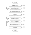
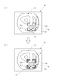
- the process of storing the endoscopic image 75 will be described with reference to the flowchart shown in FIG. 9 and the explanatory diagram shown in FIG.
- the user doctor operates the mode switching unit 13c to switch to the attention area detection mode.
- the observation target is illuminated with the illumination light for the region of interest detection mode.
- the observation target illuminated by the illumination light for the region of interest detection mode is imaged by the image sensor 38, and the image signal acquisition unit 50 acquires the endoscopic image 75 (S11).
- the display control unit 54 acquires the endoscopic image 75 and displays it on the display screen 80 of the monitor 18 in real time.
- the attention area detection unit 71 sequentially detects the attention area with respect to the acquired endoscopic image 75.
- the emphasis setting unit 72 outputs the endoscope image 75 with the first emphasis set value to the display control unit 54 (S13).
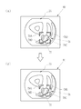
- the display control unit 54 superimposes and displays L-shaped figures 79A to 79D as highlighting on the position of the highlighting area 78 in the endoscope image 75 by using the first highlighting degree setting value (S14; FIG. 10). The state shown in (A)).
- the display control unit 54 displays the endoscopic image 75 as it is in real time.
- an image storage instruction is input to the image processing unit 53 and the image storage control unit 55.
- the emphasis setting unit 72 sets the first emphasis setting value to the second emphasis setting value. Change (S17).
- the image storage control unit 55 stores the endoscopic image 75 in the image storage unit 56 with the detection information 76B including the second emphasis setting value attached (S18).
- the image saving control unit 55 does not save the endoscopic image 75. Further, when there is an image saving instruction (Y in S15) and there is no user input information (N in S16), that is, when the user input receiving unit 57 does not accept the user input information, the first emphasis level.
- the endoscopic image 75 may be saved in the image storage unit 56 with the detection information 76A including the first emphasis setting value attached without changing the setting from the set value to the second emphasis setting value (S18). ).
- the highlighting is performed using the first highlighting setting value having a low highlighting degree (see FIG. 10A), so L as the highlighting display.
- the character figures 79A to 79D are not too conspicuous and do not interfere with the doctor's diagnosis.
- the endoscopic image 75 is saved in the image storage unit 56, the second emphasis setting value is attached and saved. Therefore, after the endoscopic examination, the still image is viewed, the report, and the presentation material.
- the region of interest can be reliably highlighted, for example, as shown in the display screen 84 shown in FIG. 10 (B).
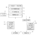
- the endoscope system 10 is connected to the inspection image viewing support system 100 via the network 102.
- the network 102 is, for example, a LAN (Local Area Network) in a hospital.
- the inspection image viewing support system 100 includes an inspection image viewing support server 128, a client terminal 130, and a server group 132, which are connected via a network 134 such as a LAN.
- the inspection image viewing support server 128 generates and updates the inspection image display screen for displaying the endoscopic image 75 based on the request from the client terminal 130, and distributes the inspection image viewing support server 128 to the client terminal 130.
- the server group 132 includes an image server 136 and a report server 138.
- the image server 136 includes an image database (hereinafter, referred to as an image DB) 140.
- the image DB 140 stores the endoscope image 75 transmitted from the endoscope system 10.
- the report server 138 includes a report database (hereinafter, referred to as a report DB) 142.
- the report DB 142 stores an examination report 144 created when the endoscopy is performed (see FIG. 11).
- the image DB 140 and the report DB 142 are databases that can be searched by keywords such as a patient ID (Identification Data) assigned to each patient and an examination ID assigned to each endoscopy.
- the examination report 144 is a report in which a doctor such as an inspector who has performed an endoscopic examination browses the endoscopic image 75 and summarizes medical findings and the like.
- An endoscopic image 75 which is the basis of the findings, is attached to the examination report 144.
- the client terminal 130 is a terminal for viewing the endoscopic image 75 and the examination report 144, and is used by the inspector to view the endoscopic image 75 and create the examination report 144 after the examination is completed.
- the client terminal 130 is used by a doctor in a clinical department who has requested an endoscopic examination to view an endoscopic image 75 and an examination report 144.
- the client terminal 130 is, for example, a notebook type or desktop type personal computer.
- the doctor uses the client terminal 130 to access the inspection image viewing support server 128, reads out the saved endoscopic image 75 and the inspection report 144, and browses them.
- the examination report 144 includes a report body 144a, examination identification information, patient identification information, and creator information.
- the report body 144a has an endoscopic examination examiner's findings 146 and an endoscopic image 75 attached to the examination report 144.
- the endoscopic image 75 is the endoscopic image 75 on which the findings 146 are based.
- the examiner In preparing the examination report 144, the examiner inputs the findings 146 while observing the plurality of endoscopic images 75 obtained by the performed endoscopic examination, and inputs the endoscopic images 75 as the basis of the findings. Attached to inspection report 144.
- the endoscopic image 75 is attached to the examination report 144, for example, the endoscopic image 75 is converted into the form of the thumbnail image 75S.
- the endoscopic image 75 may be inserted into the examination report 144 as it is, or the findings 146 and the endoscopic image 75 may be switched in a separate window.
- the endoscopic image 75 is highlighted using the inspection information 76B including the second emphasis setting value.
- the inspection information 76B including the second emphasis setting value.
- the second emphasis setting value which has a different highlighting shape from the first emphasis setting value, is used, the area of interest can be reliably highlighted.
- the highlighting by the second emphasis setting value is set to have a higher emphasis than the highlighting by the first emphasis setting value, so that the lesion portion 77 as the area of interest is surely set. It is possible to highlight in, and it is easy for doctors to notice that there is an area of interest.
- the line thickness of the L-shaped figures 79A to 79D is changed with respect to the highlighting by the first highlighting degree setting value, so that the area of interest is further expanded. It can be highlighted without fail.
- FIG. 13 (A) shows an example of highlighting the lesion 77 in the endoscopic image 75 using the first emphasis set value
- FIG. 13 (B) shows the first emphasis.
- An example is shown in which the lesion portion 77 in the endoscopic image 75 is highlighted by using the second emphasis setting value in which the number of lines of the frame shape is different from the set value.
- the difference in line color is expressed by the size of the shaded mesh, and each shaded portion is actually colored with one color. ..
- the emphasis setting unit 72 changes the setting from the first emphasis setting value to the second emphasis setting value
- the number of lines of the L-shaped figures 79A to 79D is changed as the shape of the highlighting.
- the highlighting by the second emphasis setting value has a higher emphasis than the highlighting by the first emphasis setting value, that is, the number of lines of the L-shaped figures 79A to 79D is increased. Set a lot.
- the other configurations are the same as those of the endoscope system 10 of the first embodiment.
- the L-shaped figures 79A to 79D are one, respectively, as in the first embodiment. It is made up of book lines.
- the L-shaped figures 79A to 79D are a single line and a line surrounding the line. It is formed by a double line consisting of. Further, in the present embodiment, the L-shaped figures 79A to 79D are formed of double lines having different colors from each other.
- the image processing unit 53, the display control unit 54, and the image storage control unit 55 highlight the endoscopic image 75 using the first emphasis setting value, as in the first embodiment.
- the endoscopic image 75 is saved with the detection information 76B including the emphasis setting value of.
- the highlighting is performed using the first highlighting setting value having a low highlighting degree (see FIG. 13 (A)), so that the L-shaped figure as the highlighting is displayed. 79A-79D do not stand out too much.
- the second emphasis setting value the number of lines in the frame shape is changed to a setting different from that of the first emphasis setting value, so after endoscopy, still image viewing, reports, etc.
- the region of interest can be reliably highlighted, for example, as shown in the display screen 85 shown in FIG. 13 (B).
- the present invention when the setting is changed from the first emphasis setting value to the second emphasis setting value, an example of changing the setting in one step is given as a shape change of the highlighting.
- the present invention is not limited to this, and the setting may be changed in a plurality of steps.
- the display control unit 54 displays the setting change screen 86 as shown in FIGS. 14A and 14B on the monitor 18. Let me.
- the setting change is executed with the highlighting example 87A before the setting change, the highlighting examples 87B and 87C after the setting change, the stage selection buttons 88A and 88B for selecting the setting change stage (level), and the setting change.
- the execution selection buttons 89A and 89B for selecting whether or not to perform are displayed.
- the highlighting example 87A before the setting change shows an example in which the lesion portion 77 is highlighted using the first highlighting degree setting value.
- the highlighting example 87B after the first step setting change is displayed, and in the example shown in FIG. 14 (B), two steps are displayed.
- the highlighting example 87C after changing the eye setting is displayed.
- the stage selection button 88A is attached with the character "1" indicating the first stage setting change
- the stage selection button 88B is attached with the character "2" indicating the second stage setting change.
- the step selection button 88A is selected, and in the example shown in FIG. 14B, the step selection button 88B is selected.
- the emphasis setting unit 72 changes the setting from the first emphasis setting value to the second emphasis setting value
- the line thickness of the L-shaped figures 79A to 79D is changed as the highlighting shape change. Change the line thickness and change the line thickness according to the setting change stage.
- the highlighting by the second emphasis setting value is set to have a higher emphasis than the highlighting by the first emphasis setting value, and the emphasis is made larger in the setting change of the second stage than in the first stage. ..
- the line thickness T1 2pixel of the L-shaped figures 79A to 79D (highlighting example 87A in FIG. 14A), and the first step.
- the line thickness T3 7pixel of the L-shaped figures 79A to 79D (highlighting example 87C in FIG. 14B). It becomes.
- the execution selection buttons 89A and 89B are the same as the selection buttons 83A and 83B of the first embodiment, and in the state shown in FIGS. 14A and 14B, the execution selection button 89B is selected. Shown.
- the user selects either the first stage or the second stage setting change by selecting the stage selection buttons 88A and 88B.
- the user can confirm the highlighting examples 87A, 87B or 87C and determine whether or not to change the setting.
- the user input reception unit 57 sets and changes the highlighting as the user input information. Accept the stage of change.
- the execution selection button 89A is selected, the user input receiving unit 57 determines that the user input information has not been accepted, and does not output the user input information to the emphasis setting unit 72.
- the user input receiving unit 57 receives the user input information by the user's input operation, and then outputs the user input information to the emphasis setting unit 72.
- the emphasis setting unit 72 changes the setting from the first emphasis setting value to the second emphasis setting value according to the stage of setting change.
- the image storage control unit 55 attaches the detection information 76B including the second emphasis setting value to the endoscopic image 75 when storing the endoscopic image 75. Is stored in the image storage unit 56.
- the setting when the first emphasis setting value is changed to the second emphasis setting value, the setting is changed in two steps as the shape of the highlighting. Not limited to this, the setting may be changed in three or more steps. In this case, it is preferable that the user displays a setting change screen or the like, performs an input operation, and selects any one of three or more stages of setting change, as in the third embodiment.
- the display control unit 54 shows an example in which four L-shaped figures 79A to 79D surrounding the lesion portion 77 are superimposed and displayed on the endoscopic image 75 as highlighting.
- the highlighting may be composed of one frame shape.
- a rectangular frame-shaped figure 92 surrounding the lesion 77 is superimposed and displayed at the position of the highlighted area 78 as highlighting. ..
- FIG. 15 (A) shows an example of highlighting the lesion 77 using the first emphasis set value
- FIG. 15 (B) shows the figure 92 with respect to the first emphasis set value.
- the user input receiving unit 57 receives the user input information by the input operation of the console 19, but the user input receiving unit 57 is not limited to this, and is not limited to this, and is limited to a press detection device such as a mouse, a foot pedal or a touch pad, a keyboard, and voice input.
- User input information can be received by various input devices such as a device and a touch panel input device.
- any of the operation buttons provided on the endoscope 12 is used as an operation button for selecting the setting change, and the user input reception unit 57 receives the user input information when the input operation is performed by the operation button. May be good.
- the detection information 76B includes information such as the position information, dimensions, and type of lesion of the lesion as a region of interest, but the detection information 76B is not limited to this. It may be malignant or benign, the degree of lesion progression, the presence or absence of treatment, findings, the site or organ where the lesion is present, or patient information.
- the image storage control unit 55 stores the endoscopic image 75 in the image storage unit 56 in the processor device 16 with the detection information 76B including the second emphasis setting value attached.
- the present invention is not limited to this, and when the processor device 16 can be connected to the network, an endoscopic image is sent to an image storage server (not shown) connected to the network in place of or in addition to the image storage unit 56. You may want to store 75.
- the still image is stored as the endoscopic image 75, but the present invention is not limited to this, and a moving image may be used.
- the highlighted figure is an L-shaped figure 79A to 79D or a square frame shape, but the present invention is not limited to this, and a polygon other than a rectangle (quadrangle), a circle, an ellipse, or the like can be used. Any frame shape that can surround the area of interest is sufficient.
- the highlighting of the area of interest is not limited to the above, as long as it is an image process that can be visually distinguished from the surroundings, such as saturation change processing, contrast processing, negative / positive inversion processing, and filtering processing. good.
- the highlighting by image processing of the region of interest and the highlighting by the graphic surrounding the lesion portion in each of the above embodiments may be combined.
- the four-color LEDs 20a to 20d are used to illuminate the observation target, but a laser light source and a phosphor may be used to illuminate the observation target. Further, in each of the above embodiments, the four-color LEDs 20a to 20d are used to illuminate the observation target, but a white light source such as a xenon lamp and a rotation filter may be used to illuminate the observation target. Further, instead of the color image sensor 38, a monochrome image sensor may be used to image the observation target.
- the hardware structure of the processing unit (processing unit) that executes various processes is Various processors as shown below.
- Various processors include CPU (Central Processing Unit), GPU (Graphical Processing Unit), FPGA (Field Programmable Gate Array), which are general-purpose processors that execute software (programs) and function as various processing units.
- CPU Central Processing Unit
- GPU Graphic Processing Unit
- FPGA Field Programmable Gate Array
- PLD Programmable Logic Device
- PLD Programmable Logic Device
- dedicated electric circuits which are processors with a circuit configuration specially designed to execute various processes. ..
- One processing unit may be composed of one of these various processors, or a combination of two or more processors of the same type or different types (for example, a plurality of FPGAs, a combination of a CPU and an FPGA, or a CPU. And GPU, etc.). Further, a plurality of processing units may be configured by one processor. As an example of configuring a plurality of processing units with one processor, first, as represented by a computer such as a client or a server, one processor is configured by a combination of one or more CPUs and software. There is a form in which this processor functions as a plurality of processing units.
- SoC System On Chip
- a processor that realizes the functions of the entire system including a plurality of processing units with one IC (Integrated Circuit) chip is used.
- the various processing units are configured by using one or more of the above-mentioned various processors as a hardware-like structure.
- the hardware structure of these various processors is, more specifically, an electric circuit in the form of a combination of circuit elements such as semiconductor elements.
Landscapes
- Health & Medical Sciences (AREA)
- Engineering & Computer Science (AREA)
- Public Health (AREA)
- Medical Informatics (AREA)
- General Health & Medical Sciences (AREA)
- Nuclear Medicine, Radiotherapy & Molecular Imaging (AREA)
- Life Sciences & Earth Sciences (AREA)
- Physics & Mathematics (AREA)
- Primary Health Care (AREA)
- Radiology & Medical Imaging (AREA)
- Epidemiology (AREA)
- Surgery (AREA)
- Biomedical Technology (AREA)
- Multimedia (AREA)
- Theoretical Computer Science (AREA)
- General Physics & Mathematics (AREA)
- Pathology (AREA)
- Animal Behavior & Ethology (AREA)
- Biophysics (AREA)
- Veterinary Medicine (AREA)
- Molecular Biology (AREA)
- Heart & Thoracic Surgery (AREA)
- Optics & Photonics (AREA)
- Urology & Nephrology (AREA)
- Data Mining & Analysis (AREA)
- Databases & Information Systems (AREA)
- Endoscopes (AREA)
Priority Applications (2)
| Application Number | Priority Date | Filing Date | Title |
|---|---|---|---|
| JP2022515450A JPWO2021210676A1 (https=) | 2020-04-16 | 2021-04-16 | |
| US18/046,788 US12620474B2 (en) | 2020-04-16 | 2022-10-14 | Medical image processing apparatus, endoscope system, method of operating medical image processing apparatus, and non-transitory computer readable medium |
Applications Claiming Priority (2)
| Application Number | Priority Date | Filing Date | Title |
|---|---|---|---|
| JP2020073517 | 2020-04-16 | ||
| JP2020-073517 | 2020-04-16 |
Related Child Applications (1)
| Application Number | Title | Priority Date | Filing Date |
|---|---|---|---|
| US18/046,788 Continuation US12620474B2 (en) | 2020-04-16 | 2022-10-14 | Medical image processing apparatus, endoscope system, method of operating medical image processing apparatus, and non-transitory computer readable medium |
Publications (1)
| Publication Number | Publication Date |
|---|---|
| WO2021210676A1 true WO2021210676A1 (ja) | 2021-10-21 |
Family
ID=78084941
Family Applications (1)
| Application Number | Title | Priority Date | Filing Date |
|---|---|---|---|
| PCT/JP2021/015712 Ceased WO2021210676A1 (ja) | 2020-04-16 | 2021-04-16 | 医療画像処理装置、内視鏡システム及び医療画像処理装置の作動方法並びに医療画像処理装置用プログラム |
Country Status (2)
| Country | Link |
|---|---|
| JP (1) | JPWO2021210676A1 (https=) |
| WO (1) | WO2021210676A1 (https=) |
Cited By (1)
| Publication number | Priority date | Publication date | Assignee | Title |
|---|---|---|---|---|
| WO2024004542A1 (ja) * | 2022-06-29 | 2024-01-04 | 富士フイルム株式会社 | 診断支援装置、超音波内視鏡、診断支援方法、及びプログラム |
Citations (1)
| Publication number | Priority date | Publication date | Assignee | Title |
|---|---|---|---|---|
| JP2019153249A (ja) * | 2018-03-06 | 2019-09-12 | 富士フイルム株式会社 | 医用画像処理装置、医用画像処理方法、及び医用画像処理プログラム |
Family Cites Families (8)
| Publication number | Priority date | Publication date | Assignee | Title |
|---|---|---|---|---|
| JP5349384B2 (ja) * | 2009-09-17 | 2013-11-20 | 富士フイルム株式会社 | 医用画像表示装置および方法並びにプログラム |
| WO2017073338A1 (ja) * | 2015-10-26 | 2017-05-04 | オリンパス株式会社 | 内視鏡画像処理装置 |
| WO2017110459A1 (ja) * | 2015-12-22 | 2017-06-29 | オリンパス株式会社 | 内視鏡用画像処理装置及び内視鏡システム |
| WO2017216922A1 (ja) * | 2016-06-16 | 2017-12-21 | オリンパス株式会社 | 画像処理装置及び画像処理方法 |
| WO2019146066A1 (ja) * | 2018-01-26 | 2019-08-01 | オリンパス株式会社 | 内視鏡画像処理装置、内視鏡画像処理方法及びプログラム |
| JP6906462B2 (ja) * | 2018-02-28 | 2021-07-21 | 富士フイルム株式会社 | 医用画像表示装置、方法およびプログラム |
| WO2019193983A1 (ja) * | 2018-04-04 | 2019-10-10 | 富士フイルム株式会社 | 医療文書表示制御装置、医療文書表示制御方法、及び医療文書表示制御プログラム |
| CN111936032B (zh) * | 2018-04-13 | 2024-03-26 | 富士胶片株式会社 | 图像处理装置、内窥镜系统及图像处理方法 |
-
2021
- 2021-04-16 WO PCT/JP2021/015712 patent/WO2021210676A1/ja not_active Ceased
- 2021-04-16 JP JP2022515450A patent/JPWO2021210676A1/ja active Pending
Patent Citations (1)
| Publication number | Priority date | Publication date | Assignee | Title |
|---|---|---|---|---|
| JP2019153249A (ja) * | 2018-03-06 | 2019-09-12 | 富士フイルム株式会社 | 医用画像処理装置、医用画像処理方法、及び医用画像処理プログラム |
Cited By (1)
| Publication number | Priority date | Publication date | Assignee | Title |
|---|---|---|---|---|
| WO2024004542A1 (ja) * | 2022-06-29 | 2024-01-04 | 富士フイルム株式会社 | 診断支援装置、超音波内視鏡、診断支援方法、及びプログラム |
Also Published As
| Publication number | Publication date |
|---|---|
| US20230101620A1 (en) | 2023-03-30 |
| JPWO2021210676A1 (https=) | 2021-10-21 |
Similar Documents
| Publication | Publication Date | Title |
|---|---|---|
| JP6785948B2 (ja) | 医療用画像処理装置及び内視鏡システム並びに医療用画像処理装置の作動方法 | |
| US20190374088A1 (en) | Endoscope system and operation method therefor | |
| JP7337073B2 (ja) | 医用画像処理装置及び内視鏡システム並びに医用画像処理装置の作動方法 | |
| JP7047122B2 (ja) | 医用画像処理装置及び内視鏡システム並びに医用画像処理装置の作動方法 | |
| US20220277449A1 (en) | Medical image processing device | |
| JP7335399B2 (ja) | 医用画像処理装置及び内視鏡システム並びに医用画像処理装置の作動方法 | |
| JP7610582B2 (ja) | 医療画像処理装置、内視鏡システム及び医療画像処理装置の作動方法並びに医療画像処理装置用プログラム | |
| JP7402314B2 (ja) | 医用画像処理システム、医用画像処理システムの作動方法 | |
| JP7610342B2 (ja) | 内視鏡システム | |
| JPWO2019163540A1 (ja) | 内視鏡システム | |
| JP7495511B2 (ja) | 医用画像処理装置及び医用画像処理装置の作動方法並びに医用画像処理装置用プログラム | |
| JP7130043B2 (ja) | 医用画像処理装置及び内視鏡システム並びに医用画像処理装置の作動方法 | |
| JP7386347B2 (ja) | 内視鏡システム及びその作動方法 | |
| WO2021210676A1 (ja) | 医療画像処理装置、内視鏡システム及び医療画像処理装置の作動方法並びに医療画像処理装置用プログラム | |
| US12620474B2 (en) | Medical image processing apparatus, endoscope system, method of operating medical image processing apparatus, and non-transitory computer readable medium | |
| JP2022090759A (ja) | 医用画像処理システム、医用画像処理システムの作動方法 |
Legal Events
| Date | Code | Title | Description |
|---|---|---|---|
| 121 | Ep: the epo has been informed by wipo that ep was designated in this application |
Ref document number: 21788995 Country of ref document: EP Kind code of ref document: A1 |
|
| ENP | Entry into the national phase |
Ref document number: 2022515450 Country of ref document: JP Kind code of ref document: A |
|
| NENP | Non-entry into the national phase |
Ref country code: DE |
|
| 122 | Ep: pct application non-entry in european phase |
Ref document number: 21788995 Country of ref document: EP Kind code of ref document: A1 |