WO2021210360A1 - 計測装置、計測装置制御方法および計測装置制御プログラム - Google Patents
計測装置、計測装置制御方法および計測装置制御プログラム Download PDFInfo
- Publication number
- WO2021210360A1 WO2021210360A1 PCT/JP2021/012013 JP2021012013W WO2021210360A1 WO 2021210360 A1 WO2021210360 A1 WO 2021210360A1 JP 2021012013 W JP2021012013 W JP 2021012013W WO 2021210360 A1 WO2021210360 A1 WO 2021210360A1
- Authority
- WO
- WIPO (PCT)
- Prior art keywords
- current
- phase
- voltage
- measurement system
- phases
- Prior art date
Links
- 238000005259 measurement Methods 0.000 title claims abstract description 154
- 238000000034 method Methods 0.000 title claims abstract description 95
- 238000004364 calculation method Methods 0.000 claims abstract description 19
- 238000012795 verification Methods 0.000 claims description 26
- 230000003111 delayed effect Effects 0.000 claims description 17
- 238000009434 installation Methods 0.000 claims description 14
- 230000008859 change Effects 0.000 claims description 9
- 230000010363 phase shift Effects 0.000 claims description 6
- 238000010586 diagram Methods 0.000 description 30
- 230000008569 process Effects 0.000 description 27
- 230000018199 S phase Effects 0.000 description 18
- 238000004891 communication Methods 0.000 description 17
- 230000006870 function Effects 0.000 description 14
- 229910001219 R-phase Inorganic materials 0.000 description 12
- 238000004458 analytical method Methods 0.000 description 6
- 230000005540 biological transmission Effects 0.000 description 4
- 230000007704 transition Effects 0.000 description 4
- 238000004804 winding Methods 0.000 description 4
- 230000016507 interphase Effects 0.000 description 3
- 238000005070 sampling Methods 0.000 description 3
- 230000002596 correlated effect Effects 0.000 description 2
- 238000005516 engineering process Methods 0.000 description 2
- 230000001939 inductive effect Effects 0.000 description 2
- 239000003990 capacitor Substances 0.000 description 1
- 230000001276 controlling effect Effects 0.000 description 1
- 238000012937 correction Methods 0.000 description 1
- 230000006866 deterioration Effects 0.000 description 1
- 238000012986 modification Methods 0.000 description 1
- 230000004048 modification Effects 0.000 description 1
- 230000007935 neutral effect Effects 0.000 description 1
- 230000002093 peripheral effect Effects 0.000 description 1
Images


Classifications
-
- G—PHYSICS
- G01—MEASURING; TESTING
- G01R—MEASURING ELECTRIC VARIABLES; MEASURING MAGNETIC VARIABLES
- G01R25/00—Arrangements for measuring phase angle between a voltage and a current or between voltages or currents
-
- G—PHYSICS
- G01—MEASURING; TESTING
- G01R—MEASURING ELECTRIC VARIABLES; MEASURING MAGNETIC VARIABLES
- G01R19/00—Arrangements for measuring currents or voltages or for indicating presence or sign thereof
- G01R19/25—Arrangements for measuring currents or voltages or for indicating presence or sign thereof using digital measurement techniques
- G01R19/2513—Arrangements for monitoring electric power systems, e.g. power lines or loads; Logging
-
- G—PHYSICS
- G01—MEASURING; TESTING
- G01R—MEASURING ELECTRIC VARIABLES; MEASURING MAGNETIC VARIABLES
- G01R29/00—Arrangements for measuring or indicating electric quantities not covered by groups G01R19/00 - G01R27/00
- G01R29/18—Indicating phase sequence; Indicating synchronism
Definitions
- the present invention relates to a measurement system, a measurement system control method, and a measurement system control program.
- Patent Document 1 device information for identifying a model of an electric device is acquired, current waveform data of a predetermined operating section is extracted, parameters used for identifying the electric device are extracted, and the electric device is described.
- a model identification system that identifies the model is described.
- Patent Document 2 describes a technique for determining an operating state of a power source by using a two-power metering method.
- the present invention has been made in view of the above circumstances, and is a measurement system capable of calculating changes in the current phases of three phases at low cost even when the rotation direction of the three-phase power is unknown.
- One purpose is to provide a measurement system control method and a measurement system control program.
- the measurement system of the embodiment is a line voltage of the first phase and the second phase of a three-phase power line composed of three phases of the first phase, the second phase and the third phase.
- a first voltage measuring unit that measures the first voltage
- a first current measuring unit that measures the first current that is the current of the first phase
- a third that measures the third current that is the current of the third phase.
- the current measuring unit, the determination unit that determines the rotation direction of the three phases based on the first voltage and the first current, and the first current, the third current, and the second phase based on at least the determination of the rotation direction by the determination unit. It is provided with a calculation unit for calculating the change in the current phase due to the load device at each of the second currents, which is the current of the above.
- the measurement system of the embodiment has a second voltage measuring unit that measures the second voltage, which is the line voltage between the second and third phases, and a determination unit based on the second voltage and the third current. It may further include a verification unit for verifying the rotation directions of the three phases determined in.
- the determination unit may determine an installation error of the third current measurement unit based on the verification result of the rotation direction.
- the determination unit may determine the rotation direction of the three phases based on the phase difference between the first voltage and the first current.
- an installation error of the third current measurement unit may be determined based on the verification result of the rotation direction.
- the determination unit rotates the three phases based on whether the phase of the first voltage is ahead of the phase of the first current or is behind the phase of the first current. It may determine the direction.
- the determination unit may determine the rotation direction of the three phases based on the power values calculated from the first voltage and the first current.
- the determination unit calculates from the first power value calculated from the first current whose phase is advanced from the first voltage and the first current whose phase is delayed from the first voltage.
- the second power value to be calculated may be calculated, and the rotation directions of the three phases may be determined based on the comparison of the magnitudes of the first power value and the second power value.
- the measurement system control method of the embodiment is a measurement system control method for controlling the measurement system, from the three phases of the first phase, the second phase, and the third phase.
- a first voltage measurement step for measuring the first voltage which is the line voltage between the first and second phases of the three-phase power line
- a first current measurement step for measuring the first current, which is the current for the first phase.
- a determination step of determining the rotation direction of the three phases based on the first voltage and the first current, and a calculation step of calculating the phase shift of the first current based on the determination of the rotation direction in the determination step are included.
- the measurement system control program of the embodiment is applied to the measurement system with the first phase and the first phase of the three-phase power line composed of the three phases of the first phase, the second phase and the third phase.
- the first voltage measurement function that measures the first voltage, which is the line voltage of the two phases
- the first current measurement function that measures the first current, which is the current of the first phase
- a determination function for determining the rotation direction of the three phases and a calculation function for calculating the phase shift of the first current based on the determination of the rotation direction in the determination function are realized.
- the measurement system is a first-phase and second-phase line voltage of a three-phase power line composed of three phases, a first phase, a second phase, and a third phase.
- One voltage is measured, the first current, which is the current of the first phase, is measured, the third current, which is the current of the third phase, is measured, and the rotation directions of the three phases are determined based on the first voltage and the first current.
- the three-phase power is determined by calculating the change in the current phase due to the load device in each of the first current, the third current, and the second current, which is the current of the second phase, based on at least the determination of the rotation direction. Even when the rotation direction is unknown, it is possible to calculate the change in the current phase for three phases at low cost.
- the second determination method of the phase rotation direction in the measurement system of the embodiment is a waveform diagram explaining (A) the case where the power value is the maximum and (B) the case where the power value is the minimum. It is a flowchart which shows an example of the operation of the 2nd determination method of the phase rotation direction in the measurement system of embodiment.
- A a positive phase waveform based on the RS-phase voltage
- B a waveform for explaining the measurement waveform at the time of CT installation error. It is a figure.
- FIG. 1 is a block diagram showing an example of the configuration of the measurement system of the embodiment.
- the measurement system 10 includes a measurement device 1, a management device 2, a power meter P1, and a power meter P2.
- the measuring device 1 has a voltage measuring unit 11, a current measuring unit 12, and a communication control unit 13.
- the management device 2 includes a determination unit 21, a verification unit 22, a calculation unit 23, and a current analysis unit 24.
- the management device 2 is communicably connected to the management device 2 via the network 9.
- Each of the above-mentioned functional units of the measurement system 10 in the present embodiment will be described as a functional module realized by a measurement system control program (software) that controls the measurement system 10.
- the measurement system control program is executed by the measurement device 1 or the management device 2 in which each functional module is realized.
- the power supply 31 is a three-phase power supply including three phases of R phase, S phase and T phase.
- FIG. 1 power supply 31 illustrates a star-connected three-phase AC power supply having a neutral point N.
- the power supply 31 is connected to the load 32 by three wires, an R-phase wire, an S-phase wire, and an R-phase wire.
- the R phase may be referred to as the first phase
- the S phase may be referred to as the second phase
- the T phase may be referred to as the third phase.
- the first phase is not limited, and for example, any one of the S phase and the T phase may be used as the first phase.
- the power meter P1 has a first voltage measuring unit 111 and a first current measuring unit 121.
- the power meter P2 has a second voltage measuring unit 112 and a third current measuring unit 122.
- the first voltage measuring unit 111 may refer to the line voltage (“first voltage” or “RS line voltage”) between the R phase exemplified as the first phase and the S phase exemplified as the second phase. ) Measure the voltage waveform.
- the first current measuring unit 121 measures the current waveform of the R-phase line current (sometimes referred to as “first current” or “R-line current”).
- the second voltage measuring unit 112 measures the voltage waveform of the line voltage (TS line voltage) between the T phase and the S phase exemplified as the third phase.
- the third current measuring unit 122 measures the current waveform of the T-phase line current (sometimes referred to as “third current” or “T-line current”).
- the measured waveform data of the first voltage, the first current, the second voltage, and the third current are input to the measuring device 1.
- the voltage measuring unit 11 measures the voltage waveform measured by the first voltage measuring unit 111 and the second voltage measuring unit 112.
- the voltage measuring unit 11 may, for example, set a voltage waveform of the first voltage measured by the first voltage measuring unit 111 or the second voltage measured by the second voltage measuring unit 112 as a predetermined timing (sometimes referred to as sampling timing). ) Is sampled.
- the sampling timing is determined, for example, by a wavenumber counter (not shown) that counts the wavenumber in one second.
- the voltage measuring unit 11 measures the zero cross point based on the sampled voltage waveform.
- the zero cross point is a point when the voltage waveform becomes 0 V (sometimes referred to as “voltage 0 point”).
- the current measuring unit 12 measures the current waveforms of the first current measured by the first current measuring unit 121 and the third current measured by the third current measuring unit 122.
- the current measuring unit 12 samples, for example, the current waveform of the first current or the third current at the sampling timing.
- the current measuring unit 12 measures a zero cross point (sometimes referred to as “current 0 point”) based on the sampled current waveform.
- the communication control unit 13 controls the communication between the power meter P1 and the power meter P2 and the measuring device 1. Further, the communication control unit 13 controls communication with the management device 2 via the network 9.
- the communication control unit 13 may control either wired communication or wireless communication.
- the communication control unit 13 may control communication using a wireless LAN (Local Area Network) between the power meter P1 and the power meter P2. Further, the communication control unit 13 may control communication using the Internet protocol with the management device 2.
- LAN Local Area Network
- the management device 2 is a device capable of communicating with the measuring device 1 via the network 9, and is, for example, a server capable of communicating with a plurality of measuring devices 1.
- the determination unit 21 determines the rotation direction of the three phases of the power supply 31 based on the first voltage and the first current.
- the three-phase power supply has three phases of R phase, S phase, and T phase.
- the rotation direction of the three phases in the present embodiment is the transition direction of the three phases, and the voltage phases of the R phase, the S phase, and the T phase rotate (transition) in the order of RST.
- the rotation direction may be unknown before energization.
- the determination unit 21 enables correct measurement in the measurement system 10 by determining the rotation directions of the three phases even when the rotation directions of the three phases are unknown.
- the determination unit 21 determines the rotation direction of the three phases in at least one of the first determination method and the second determination method, which will be described later. If the direction of rotation can be determined, by measuring the voltage of one phase, the phase of the measured voltage waveform can be advanced or delayed by 120 degrees according to the direction of rotation without actually measuring the voltage of the other two phases. It is possible to calculate the voltage of the other two phases by performing the calculation.
- the rotation direction of RST is described as a positive phase and the rotation direction of TSR is a reverse phase, but the rotation direction of RST is a reverse phase and T. It may be carried out with the rotation direction of ⁇ SR as the positive phase.
- the verification unit 22 is a determination unit 21 based on the second voltage and the third current, which are the line voltages of the second phase (S phase) and the third phase (T phase) measured by the second voltage measurement unit 112. The determined rotation directions of the three phases are verified. The verification of the rotation direction is to verify whether or not the determination of the rotation direction determined by the determination unit 21 is correct. If the verification result does not contradict the judgment result, it is verified that the judgment result is correct. On the other hand, if the verification result contradicts the determination result, for example, an installation error of the third current measuring unit 122 is expected.
- the verification of the rotation direction by the verification unit 22 can be executed by the same method as the determination of the rotation direction by the determination unit 21.
- the verification by the verification unit 22 can also be executed by the same method as the first determination method. This makes it possible to share the algorithm, measurement data, and the like in the determination program used in the determination of the determination unit 21. The details of the verification method in the verification unit 22 will also be described later.
- the calculation unit 23 calculates the change in the current phase due to the load 32 in each of the first current, the third current, and the second current, which is the current of the second phase, based on at least the determination of the rotation direction by the determination unit 21. do.
- the change in the current phase due to the load 32 is the phase difference of the current with respect to the voltage in each phase due to the load 32.
- the load 32 is a load including an inductive reactance
- a delay in the current phase with respect to the voltage phase that is, a deterioration in the power factor occurs.
- the inductive reactance differs depending on the device, and the device included in the load 32 may be specified by calculating the phase change.
- the current analysis unit 24 analyzes the current of each phase.
- the current analysis unit 24 analyzes, for example, the type of equipment included in the load 32, the operating state of the equipment, and the like based on the current value, the current waveform, the phase difference from the voltage, and the like.
- the characteristics of each device that can be observed in the load current of the load 32 are stored in advance as a database, and the current analysis unit 24 compares the measured current waveform and the like with the database to determine the type of device and the like.
- the characteristics of each device include, for example, the current value, the change over time of the current value, the power factor, the shape of noise from the device mixed in the current line, and the like.
- the current analysis unit 24 may analyze the types of a plurality of devices by separating the features such as the measured current waveform for each device.
- each of the above-mentioned functional units of the measurement system 10 shows an example of the functional units of each device, and does not limit the functions of each device.
- the functional unit described as having the measuring device 1 may be implemented in the management device 2.
- the functional unit described as having the management device 2 may be implemented in the measuring device 1.
- each device does not have to have all the above-mentioned functional parts, and may have some functional parts.
- each device may have a function other than the above.
- each of the above-mentioned functional parts was explained as being realized by software. However, at least one or more of the functional units may be realized by hardware.
- any of the above functional units may be implemented by dividing one functional unit into a plurality of functional units. Further, any two or more of the above functional units may be integrated into one functional unit. That is, FIG. 1 shows the functions in the measurement system 10 expressed by functional blocks, and does not show, for example, that each functional unit is composed of a separate program file.
- each device may be a device realized by one housing or a system realized by a plurality of devices connected via a network or the like.
- the measuring device 1 or the management device 2 may realize a part or all of its functions by a virtual device such as a cloud service provided by a cloud computing system. That is, the measuring device 1 or the management device 2 may realize at least one or more of the above-mentioned functional units in another device.
- the measuring device 1 or the management device 2 may be a general-purpose computer such as a desktop PC or a server device, or may be a dedicated device having limited functions.
- FIG. 2 is a block diagram showing (A) a first example and (B) a block diagram showing a second example in the device configuration of the measurement system of the embodiment.
- the measurement system 10 includes a circuit meter 101, a circuit meter 102, a transformer 113, a transformer 114, a current transformer 123, a current transformer 124, a secondary current transformer 125, and a secondary current transformer. It has 126.
- the transformer 113 is a transformer that steps down the first voltage, which is the interphase voltage between the R phase (first phase) and the S phase (second phase), at a predetermined winding ratio.
- first voltage which is the interphase voltage between the R phase (first phase) and the S phase (second phase)
- second phase second phase
- one output line (L) is input to the circuit meter 101
- the other output line (N) is grounded and input to the circuit meter 101.
- the circuit meter 101 can measure the first voltage stepped down by the winding ratio of the transformer 113.
- the transformer 114 is a transformer that steps down the second voltage, which is the interphase voltage between the T phase (third phase) and the S phase (second phase), at a predetermined winding ratio.
- the second voltage which is the interphase voltage between the T phase (third phase) and the S phase (second phase)
- one output line (L) is input to the circuit meter 102
- the other output line (N) is grounded and input to the circuit meter 102.
- the circuit meter 102 can measure the first voltage stepped down by the winding ratio of the transformer 114.
- the current transformer 123 changes the current (first current) of the R phase (first phase).
- the secondary current transformer 125 changes the output current of the current transformer 123 to which the first current has been changed.
- the output current of the transformed secondary current transformer 125 is input to the circuit meter 101.
- the current transformer 124 changes the current (third current) of the T phase (third phase).
- the secondary current transformer 126 changes the output current of the current transformer 124 to which the third current has been changed.
- the output current of the transformed secondary current transformer 126 is input to the circuit meter 102. Further, the output current of the transformed secondary current transformer 126 is also input to the circuit meter 101.
- the S-phase current (second current) can be measured by the vector sum of the first current and the second current.
- the measurement system 10 shown in FIG. 2 (A) measures the waveforms of the RS phase voltage and the R phase current by measuring the first voltage (RS phase voltage) and the first current (R phase current). At the same time, it is possible to measure the waveforms of the TS phase voltage or the RS phase voltage and the T phase current by measuring the second voltage (TS phase voltage) and the third current (T phase current). can.
- the measurement system 10 includes a circuit meter 101, a transformer 113, a current transformer 123, a current transformer 124, a secondary current transformer 125, and a secondary current transformer 126. Note that the description overlapping with FIG. 2A may be omitted.
- the current transformer 124 changes the current (third current) of the T phase (third phase).
- the secondary current transformer 126 changes the output current of the current transformer 124 to which the third current has been changed.
- the output current of the transformed secondary current transformer 126 is input to the circuit meter 101. That is, the R-phase current and the T-phase current are input to the circuit meter 101.
- the measurement system 10 shown in FIG. 2B can measure the waveforms of the RS-phase voltage and the R-phase current by measuring the RS-phase voltage and the R-phase current, and also measures the T-phase current. Therefore, the waveforms of the RS-phase voltage and the T-phase current can be measured.
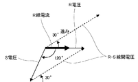
- FIG. 3 is a vector diagram illustrating a first example of the first determination method of the phase rotation direction in the measurement system of the embodiment.
- FIG. 3 shows a case where the rotation directions of the three phases are positive phases.
- the phase of the S voltage lags the phase of the R voltage by 120 degrees.
- the first voltage is an interphase voltage (RS voltage) between the R phase and the S phase.
- RS voltage interphase voltage
- the phase of the first voltage is 30 degrees ahead of the phase of the R-line current, which is the first current (the phase of the first current is It is 30 degrees behind the phase of the first voltage).
- the determination unit 21 compares the phase of the first voltage with the phase of the first current and determines that the phase of the first voltage is 30 degrees ahead of the phase of the first current. It can be determined that the rotation directions of the three phases are positive. For example, the determination unit 21 can determine that the phase of the first voltage is 30 degrees ahead of the phase of the first current by measuring the changes over time between the first voltage and the first current.
- the first determination method described above and the second determination method described later can also be carried out by the verification unit 22. That is, the verification unit 22 can determine the rotation directions of the three phases based on the first determination method or the second determination method. For example, in the above-described embodiment, the case where the rotation direction is determined by comparing the phases of the RS line voltage as the first voltage and the R current as the first current has been described, but the TS line voltage and the T current have been described.
- the first determination method can also be implemented in the phase comparison of. The rotation direction determined based on the RS line voltage and the first current coincides with the rotation direction determined based on the phase comparison between the TS line voltage and the T current. If the rotation directions do not match, there is a high possibility that the equipment has been installed incorrectly.
- the verification unit 22 determines, for example, by determining the rotation direction determined by the determination unit 21 based on the phases of the RS line voltage and the R current based on the phases of the TS line voltage and the T current. The determination result determined in the unit 21 can be verified.
- FIG. 4 is a waveform diagram illustrating a first example of the first determination method of the phase rotation direction in the measurement system of the embodiment.
- FIG. 4 is a waveform diagram showing the R voltage, the S voltage, the R current, and the RS voltage shown in FIG. 3 in time series. Similar to FIG. 3, the phase of the first voltage is 30 degrees ahead of the phase of the R line current which is the first current.
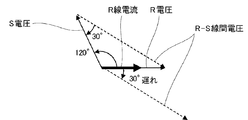
- FIG. 5 is a vector diagram illustrating a second example of the first determination method of the phase rotation direction in the measurement system 10 of the embodiment.
- FIG. 5 shows a case where the rotation directions of the three phases are opposite to each other.
- the S voltage advances 120 degrees from the R voltage. If there is no phase difference between the R-phase voltage and the R-phase current, the phase of the first voltage is 30 degrees behind the phase of the R-line current, which is the first current (the phase of the first current is the first). It is 30 degrees ahead of the voltage phase).
- the determination unit 21 compares the phase of the first voltage with the phase of the first current and determines that the phase of the first voltage is 30 degrees behind the phase of the first current, It can be determined that the rotation directions of the three phases are opposite phases.
- FIG. 6 is a waveform diagram illustrating a second example of the first determination method of the phase rotation direction in the measurement system 10 of the embodiment.
- FIG. 6 is a waveform diagram showing the R voltage, the S voltage, the R current, and the RS voltage shown in FIG. 5 in time series. Similar to FIG. 5, the phase of the first voltage lags the phase of the R line current, which is the first current, by 30 degrees.
- the determination unit 21 can determine that the phase of the first voltage is 30 degrees behind the phase of the first current by measuring the changes over time between the first voltage and the first current.
- FIG. 7 is a flowchart showing an example of the operation of the first determination method in the phase rotation direction in the measurement system 10 of the embodiment.
- the execution subject of the process is the measurement system 10
- the operations shown in the flowchart are executed in each functional unit of the measurement system 10 described in FIG.
- the measurement system 10 obtains the positions of the 0 points (zero cross points) of the first voltage and the first current with the power meter P1 measuring the RS side (step S11).
- the determination unit 21 of the management device 2 has a voltage based on the voltage waveform measured by the first voltage measurement unit 111 of the wattmeter P1 and the current waveform measured by the first current measurement unit 121. The positions of the 0 point and the 0 point of the current can be obtained.
- the measurement system 10 After executing the process of step S11, the measurement system 10 compares the positions of the voltage 0 point of the first voltage and the current 0 point of the first current (step S12). It is determined whether or not the first current lags behind the first voltage by 30 degrees (step S13). When it is determined that the first current is delayed by 30 degrees (step S13: YES), the measurement system 10 determines that the rotation directions of the three phases are the positive phases of RST (step S14).
- the measurement system 10 After executing the process of step S14, the measurement system 10 obtains the position of the 0 point (zero cross point) of the second voltage and the third current with the power meter P2 measuring the TS side (step S15).
- the determination unit 21 of the management device 2 has a voltage based on the voltage waveform measured by the second voltage measurement unit 112 of the wattmeter P2 and the current waveform measured by the third current measurement unit 122. The positions of the 0 point and the 0 point of the current can be obtained.
- the measurement system 10 After executing the process of step S15, the measurement system 10 compares the positions of the voltage 0 point of the second voltage and the current 0 point of the third current (step S16). Next, the measurement system 10 determines whether or not the third current advances by 30 degrees with respect to the second voltage (step S17). When it is determined that the third current is advanced by 30 degrees (step S17: YES), the measurement system 10 determines that the rotation directions of the three phases are the positive phases of RST (step S18). Whether or not the determination result of the rotation direction determined in the process of step S14 is correct is verified in the process of step S18.
- step S17 NO
- the measurement system 10 determines that the equipment is installed incorrectly.
- the equipment installation error is, for example, an installation error of installing the current measuring unit in the T phase and the S phase, which should be originally installed in the T phase. Since the rotation direction of the three-phase electric wire cannot be confirmed unless it is confirmed with a measuring device in the energized state, the device may be mistakenly installed in a phase different from the originally installed phase. By verifying the direction of rotation, it is possible to determine an installation error.
- step S13 when it cannot be determined that the first current is delayed by 30 degrees (step S13: NO), the measurement system 10 determines that the rotation directions of the three phases are opposite phases of TSR. Judgment (step S20).
- the measurement system 10 After executing the process of step S20, the measurement system 10 obtains the position of the 0 point (zero cross point) of the second voltage and the third current with the power meter P2 measuring the TS side (step S21).
- the determination unit 21 of the management device 2 has a voltage based on the voltage waveform measured by the second voltage measurement unit 112 of the wattmeter P2 and the current waveform measured by the third current measurement unit 122. The positions of the 0 point and the 0 point of the current can be obtained.
- the measurement system 10 After executing the process of step S21, the measurement system 10 compares the positions of the voltage 0 point of the second voltage and the current 0 point of the third current (step S22). Next, the measurement system 10 determines whether or not the third current lags the second voltage by 30 degrees (step S23). When it is determined that the third current is delayed by 30 degrees (step S23: YES), the measurement system 10 determines that the rotation directions of the three phases are opposite phases of TSR (step S24). The determination result of the rotation direction determined in the process of step S20 is verified in the process of step S24.
- step S23 NO
- the measurement system 10 determines that the equipment is installed incorrectly.
- the measurement system 10 After executing the process of step S18, the process of step S19, the process of step S24, or the process of step S25, the measurement system 10 ends the operation shown in the flowchart.
- the second determination method calculates the power value based on the measured line voltage and line current, and determines the rotation direction from the phase relationship in which the power value is maximized from the calculated power values.
- the phase relationship between the RS line voltage and the R line current is based on the RS line voltage, and the phase difference of the R line current is +30 (whether the phase is delayed by 30 degrees) or the phase difference. Is either -30 degrees (whether the phase is advanced by 30 degrees).
- the phase relationship between the TS line voltage and the T line current is based on the TS line voltage, and the phase difference of the T line current is -30 (whether the phase is advanced by 30 degrees) or the phase difference is +30. It is either a degree (whether the phase is delayed by 30 degrees).
- the power value is obtained from the product of the line voltage and the line current at each of the above phase differences. That is, with respect to the RS line voltage, the power value when the phase difference is +30 degrees for the R line current and the power value when the phase difference is -30 degrees for the R line current are calculated, and the power value is large.
- the direction of rotation can be determined based on the phase difference between the two.
- the second determination method can be performed when the load power factor is about 0.9 or more (the phase difference between the line voltage and the line current is within about ⁇ 26 degrees).
- the rotation direction can also be verified in the second determination method. For example, the phase difference at which the power value becomes the maximum value is determined from the TS line voltage and the T line current, and the determination result is verified by checking whether or not the rotation direction matches the rotation direction determined from the TS line voltage and the T line current. can do.
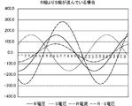
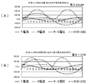
- FIG. 8 is a waveform diagram illustrating a first example of the calculation result of the first determination method in the phase rotation direction in the measurement system of the embodiment.
- FIG. 9 is a waveform diagram illustrating a second example of the calculation result of the first determination method in the phase rotation direction in the measurement system of the embodiment.
- FIG. 8 shows a case where the R-S line voltage is 30 degrees ahead of the R line current.
- the rotation direction of the three phases is the positive phase of the RS as described above.
- the power value obtained by multiplying the measured R-line current by six types of current waveforms whose phases are delayed by 30, 90, 150, 210, 270, and 330 degrees and the R-S line voltage.
- FIG. 9 shows a case where the voltage between the RS lines is delayed by 30 degrees from the R line current.
- the rotation directions of the three phases are opposite to those of the TS R as described above.
- Six types of current waveforms in which the measured R-line currents are delayed by 30, 90, 150, 210, 270, and 330 degrees are multiplied by the RS-line voltage to calculate the power value, and the six types of currents are calculated.
- the phase shift (power factor) between the phase voltage and the phase current affects the measurement.
- the phase difference at which the power value is maximized is not exactly ⁇ 30 degrees because the phase advance due to the power factor correction capacitor and the phase delay due to the motor load occur.
- load equipment in order to reduce power consumption, load equipment is designed so that the power factor during rated operation is as close to 1 as possible. Therefore, the correct phase relationship can be determined by long-time measurement for eliminating the influence of load fluctuation as much as possible, and by determining the phase relationship between both the RS side measurement and the TS side measurement. can. Further, by performing six kinds of calculations in which the phase of the current waveform is changed by 60 degrees as well as ⁇ 30 °, it is possible to detect an installation error during the sensor installation work.
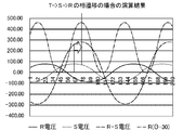
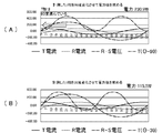
- FIG. 10 is a waveform diagram illustrating a first example of a second determination method in the phase rotation direction in the measurement system of the embodiment.
- the power measurement performs six types of operations in which the current phase is changed by 60 degrees.
- the absolute value of the power value is the largest among them. Two types of cases where the power is the smallest will be described as an example.
- FIG. 10 shows a method of detecting the phase relationship between the phase of the RS line voltage and the phase of the R current by the second determination method.
- FIG. 10A is a waveform diagram when the R-line current is advanced by 30 degrees (delayed by 330 degrees), and shows that the power value is 230.9 W, which is the maximum value among the six types.
- FIG. 10B is a waveform diagram when the R-line current is advanced by 90 degrees (delayed by 270 degrees), and shows that the absolute value of the power value is 115.5 W, which is the minimum value. Since the power value becomes maximum when the R line current is advanced by 30 degrees, it can be determined that the rotation direction is the positive phase of RST.
- FIG. 11 is a waveform diagram illustrating a second example of the second determination method of the phase rotation direction in the measurement system of the embodiment.
- FIG. 11 shows a method of detecting the phase relationship between the phase of the RS line voltage and the phase of the T current by the second determination method.
- FIG. 11A is a waveform diagram when the R-line current is advanced by 270 degrees (delayed by 90 degrees), and shows that the power value is 230.9 W, which is the maximum value among the six types. ..
- FIG. 11B is a waveform diagram when the T-line current is advanced by 330 degrees (delayed by 30 degrees), and shows that the absolute value of the power value is 115.5 W, which is the minimum value.
- the rotation direction is the positive phase of RST. For example, by performing the determination based on the T-phase current in FIG. 11 after the determination based on the R-phase current in FIG. 10, it is possible to verify the determination result based on the R-phase current.
- FIG. 12 is a flowchart showing an example of the operation of the second determination method in the phase rotation direction in the measurement system 10 of the embodiment.
- the measurement system 10 executes the process of step S31 to the process of step S35 in parallel.
- the measurement system 10 measures the RS correlation voltage and the R current, and performs an operation of advancing the current waveform of the measured R current by 30 degrees (step S31).
- the measurement system 10 After executing the process of step S31, the measurement system 10 performs a vector product of the RS correlated voltage and the R current advanced by 30 degrees, and integrates them in one cycle to calculate the power value (step S32).
- the measurement system 10 performs an operation of advancing the current waveform of the measured R current by 90 degrees (step S33). After executing the process of step S33, the measurement system 10 performs a vector product of the RS correlated voltage and the R current advanced by 90 degrees, and integrates them in one cycle to calculate the power value (step S34). The measurement system 10 performs an operation of advancing the measured R current by 150 degrees, an operation of advancing by 210 degrees, and an operation of advancing by 270 degrees, which are not shown, and calculates each power value, and further, the current waveform of the measured R current. Is performed by 330 degrees (step S35), and the power value is calculated (step S36).
- the measurement system 10 After executing the processes of steps S32 to S36, the measurement system 10 obtains the phase relationship of the R current with respect to the RS correlation voltage that maximizes the power value (step S37). Next, the measurement system 10 determines whether or not the phase relationship is +30 degrees (step S38). When it is determined that the phase relationship is +30 degrees (step S38: YES), the measurement system 10 determines that the rotation directions of the three phases are the positive phases of RST (step S39).
- step S38 determines whether or not the phase relationship is +30 degrees (-30 degrees) (step S40).
- step S40 determines that the rotation directions of the three phases are opposite phases of TSR (step S41).
- step S40 determines that the equipment is installed incorrectly (step S42). That is, in the process of step S40, it is possible to verify the determination of the rotation direction in the process of step S39 by determining whether or not it contradicts the determination in the process of step S38.
- An example of measuring the waveform when it is determined that the device is installed incorrectly by the verification in the process of step S40 will be described with reference to FIGS. 13 to 14.
- step S39 After executing the process of step S39, step S41 or step S42, the measurement system 10 ends the operation shown in the flowchart.
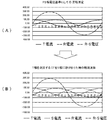
- FIG. 13 shows, as the first example of the verification method of the phase rotation direction in the measurement system of the embodiment, (A) a positive phase waveform based on the RS-phase voltage, and (B) a measurement waveform when a CT is installed incorrectly. It is a waveform diagram explaining.
- FIG. 13 (A) is a waveform diagram of the R-S phase voltage, the R current, and the T current when the rotation direction is in the positive phase.
- the determination that the rotation direction is in the positive phase can be determined from the waveform data of the RS phase voltage and the R current.
- CT current measuring unit
- FIG. 13 (B) the waveform data of the S phase current is displayed instead of the T phase current. It will be measured. In this case, the rotation direction is judged inconsistent with the judgment result in the rotation direction verification.
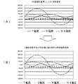
- FIG. 14 shows, as the first example of the method for verifying the phase rotation direction in the measurement system of the embodiment, (A) a reverse phase waveform based on the RS-phase voltage, and (B) a measurement waveform when a CT is installed incorrectly. It is a waveform diagram explaining.
- FIG. 14A is a waveform diagram of the R-S phase voltage, the R current, and the T current when the rotation directions are opposite to each other.
- the determination that the rotation directions are opposite to each other can be determined from the waveform data of the RS phase voltage and the R current.
- CT current measuring unit
- FIG. 14 (B) the waveform data of the S phase current is displayed instead of the T phase current. It will be measured. In this case, the rotation direction is judged inconsistent with the judgment result in the rotation direction verification.
- the program for realizing the function constituting the apparatus described in the present embodiment is recorded on a computer-readable recording medium, and the program recorded on the recording medium is read into the computer system and executed. Therefore, the above-mentioned various processes of the present embodiment may be performed.
- the "computer system” referred to here may include hardware such as an OS and peripheral devices. Further, the "computer system” includes a homepage providing environment (or a display environment) if a WWW system is used.
- the "computer-readable recording medium” includes a flexible disk, a magneto-optical disk, a ROM, a writable non-volatile memory such as a flash memory, a portable medium such as a CD-ROM, a hard disk built in a computer system, and the like. It refers to the storage device of.
- the "computer-readable recording medium” is a volatile memory inside a computer system that serves as a server or client when a program is transmitted via a network such as the Internet or a communication line such as a telephone line (for example, DRAM (Dynamic)). It also includes those that hold the program for a certain period of time, such as Random Access Memory)). Further, the program may be transmitted from a computer system in which this program is stored in a storage device or the like to another computer system via a transmission medium or by a transmission wave in the transmission medium.
- a network such as the Internet or a communication line such as a telephone line (for example, DRAM (Dynamic)). It also includes those that hold the program for a certain period of time, such as Random Access Memory)).
- the program may be transmitted from a computer system in which this program is stored in a storage device or the like to another computer system via a transmission medium or by a transmission wave in the transmission medium.
- the "transmission medium” for transmitting a program refers to a medium having a function of transmitting information, such as a network (communication network) such as the Internet or a communication line (communication line) such as a telephone line.
- the above program may be for realizing a part of the above-mentioned functions. Further, it may be a so-called difference file (difference program) that realizes the above-mentioned function in combination with a program already recorded in the computer system.
- Measuring device 10 Measuring system 101 Circuit meter 102 Circuit meter 11 Voltage measuring unit P1 Power meter P2 Power meter 111 1st voltage measuring unit 112 2nd voltage measuring unit 113 Transformer 114 Transformer 12 Current measuring unit 121 1st current measuring unit 122 Third current measuring unit 123 Current transformer 124 Current transformer 125 Secondary current transformer 126 Secondary current transformer 13 Communication control unit 2 Management device 21 Judgment unit 22 Verification unit 23 Calculation unit 24 Current analysis unit 31 Power supply 32 Load 9 network
Landscapes
- Physics & Mathematics (AREA)
- General Physics & Mathematics (AREA)
- Engineering & Computer Science (AREA)
- Power Engineering (AREA)
- Testing Of Short-Circuits, Discontinuities, Leakage, Or Incorrect Line Connections (AREA)
- Remote Monitoring And Control Of Power-Distribution Networks (AREA)
Abstract
三相電力の回転方向が不明の場合であっても、低コストで三相分の電流位相の変化を算出することができる、計測システム、計測システム制御方法および計測システム制御プログラムを提供する。実施形態の計測システムは、第1相、第2相および第3相の三相からなる三相式電力線の第1相と第2相の線間電圧である第1電圧を測定する第1電圧測定部と、第1相の電流である第1電流を測定する第1電流測定部と、第3相の電流である第3電流を測定する第3電流測定部と、第1電圧と第1電流に基づき、三相の回転方向を判定する判定部と、判定部における回転方向の判定に少なくとも基づき、第1電流、第3電流、および第2相の電流である第2電流のそれぞれにおける負荷装置による電流位相の変化を算出する算出する算出部と、を備える。
Description
本発明は、計測システム、計測システム制御方法および計測システム制御プログラムに関する。
近年、電源部に流れる電流波形を計測して負荷としての各電気機器に流れる電流をそれぞれ分離して解析する技術がある。例えば、特許文献1には、電気機器の機種を識別するための機器情報を取得し、所定の動作区間の電流波形のデータを抽出し、電気機器の識別に用いるパラメータを抽出し、電気機器の機種を識別する機種識別システムが記載されている。
また、三相電力を二台の電力計で計測する二電力計法を用いた測定技術がある。例えば、特許文献2には、二電力計法を用いて、電源の運転状態を判別する技術が記載されている。
しかし、三相電源において各電気機器に流れる電流波形を解析するためには、三相それぞれにおける電圧と電流を計測して、電圧位相に対する負荷装置による電流位相の変化を算出する必要がある。このため、三相電源においては三相分の電圧計測と電流計測をするためのセンサを設置して装置コストが高くなってしまう場合があった。
また、二電力計法においては三相電源の回転方向を判断することができないため、三相電力の回転方向が不明の場合2台の電力計を三相電源の回転方向とは逆方向に設置して正しい測定ができない場合があった。
本発明は上記事情に鑑みてなされたものであり、三相電力の回転方向が不明の場合であっても、低コストで三相分の電流位相の変化を算出することができる、計測システム、計測システム制御方法および計測システム制御プログラムを提供することを一つの目的とする。
(1)上記の課題を解決するため、実施形態の計測システムは、第1相、第2相および第3相の三相からなる三相式電力線の第1相と第2相の線間電圧である第1電圧を測定する第1電圧測定部と、第1相の電流である第1電流を測定する第1電流測定部と、第3相の電流である第3電流を測定する第3電流測定部と、第1電圧と第1電流に基づき、三相の回転方向を判定する判定部と、判定部における回転方向の判定に少なくとも基づき、第1電流、第3電流、および第2相の電流である第2電流のそれぞれにおける負荷装置による電流位相の変化を算出する算出する算出部と、を備える。
(2)また、実施形態の計測システムは、第2相と第3相の線間電圧である第2電圧を測定する第2電圧測定部と、第2電圧と第3電流に基づき、判定部で判定された三相の回転方向を検証する検証部とをさらに備えるものであってもよい。
(3)また、実施形態の計測システムにおいて、判定部は、回転方向の検証結果に基づき、第3電流測定部の設置ミスを判断するものであってもよい。判定部は、第1電圧と第1電流の位相差に基づき、三相の回転方向を判定するものであってもよい。
(4)また、実施形態の計測システムにおいて、回転方向の検証結果に基づき、第3電流測定部の設置ミスを判断するものであってもよい。
(5)また、実施形態の計測システムにおいて、判定部は、第1電圧の位相が、第1電流の位相より進んでいるか、または第1電流の位相より遅れているかに基づき、三相の回転方向を判定するものであってもよい。
(6)また、実施形態の計測システムにおいて、判定部は、第1電圧と第1電流から算出される電力値に基づき、三相の回転方向を判定するものであってもよい。
(7)また、実施形態の計測システムにおいて、判定部は、第1電圧と位相を進めた第1電流から算出される第1電力値と、第1電圧と位相を遅らせた第1電流から算出される第2電力値とを算出し、第1電力値と第2電力値の大きさの比較に基づき、三相の回転方向を判定するものであってもよい。
(8)上記の課題を解決するため、実施形態の計測システム制御方法は、計測システムを制御するための計測システム制御方法であって、第1相、第2相および第3相の三相からなる三相式電力線の第1相と第2相の線間電圧である第1電圧を測定する第1電圧測定ステップと、第1相の電流である第1電流を測定する第1電流測定ステップと、第1電圧と第1電流に基づき、三相の回転方向を判定する判定ステップと、判定ステップにおける回転方向の判定に基づき、第1電流の位相のずれを算出する算出ステップとを含む。
(9)上記の課題を解決するため、実施形態の計測システム制御プログラムは、計測システムに、第1相、第2相および第3相の三相からなる三相式電力線の第1相と第2相の線間電圧である第1電圧を測定する第1電圧測定機能と、第1相の電流である第1電流を測定する第1電流測定機能と、第1電圧と第1電流に基づき、三相の回転方向を判定する判定機能と、判定機能における回転方向の判定に基づき、第1電流の位相のずれを算出する算出機能とを実現させる。
本発明の一つの実施形態によれば、計測システムは、第1相、第2相および第3相の三相からなる三相式電力線の第1相と第2相の線間電圧である第1電圧を測定し、第1相の電流である第1電流を測定し、第3相の電流である第3電流を測定し、第1電圧と第1電流に基づき、三相の回転方向を判定し、回転方向の判定に少なくとも基づき、第1電流、第3電流、および第2相の電流である第2電流のそれぞれにおける負荷装置による電流位相の変化を算出することにより、三相電力の回転方向が不明の場合であっても、低コストで三相分の電流位相の変化を算出することができる。
以下、図面を参照して本発明の一実施形態における、計測システム、計測システム制御方法および計測システム制御プログラムについて詳細に説明する。
先ず、図1を用いて、計測システムの構成を説明する。図1は、実施形態の計測システムの構成の一例を示すブロック図である。
図1において、計測システム10は、計測装置1、管理装置2、電力計P1および電力計P2を有する。計測装置1は、電圧計測部11、電流計測部12および通信制御部13を有する。管理装置2は、判定部21、検証部22、算出部23および電流解析部24を有する。管理装置2は、ネットワーク9を介して管理装置2と通信可能に接続されている。本実施形態における計測システム10の上記各機能部は、計測システム10を制御する計測システム制御プログラム(ソフトウェア)によって実現される機能モジュールであるものとして説明する。計測システム制御プログラムは、それぞれの機能モジュールが実現される計測装置1または管理装置2でそれぞれ実行される。
電源31は、R相、S相およびT相の三相からなる三相電源である。図1電源31は、中性点Nを有するスター結線の三相交流電源を例示している。電源31は、R相線、S相線およびR相線の三線によって負荷32に接続されている。本実施形態においては、三相の中で、R相を第1相、S相を第2相、さらにT相を第3相と言う場合があるが、第1相~第3相はこれに限定されるものではなく、例えば、S相またはT相のいずれか1相を第1相としてもよい。
電力計P1は、第1電圧測定部111および第1電流測定部121を有する。電力計P2は、第2電圧測定部112および第3電流測定部122を有する。
第1電圧測定部111は、第1相として例示するR相と第2相として例示するS相との線間電圧(「第1電圧」または「R-S線間電圧」という場合がある。)の電圧波形を測定する。第1電流測定部121は、R相線の電流(「第1電流」または「R線電流」という場合がある。)の電流波形を測定する。第2電圧測定部112は、第3相として例示するT相とS相との線間電圧(T-S線間電圧)の電圧波形を測定する。また、第3電流測定部122は、T相線の電流(「第3電流」または「T線電流」という場合がある。)の電流波形を測定する。測定された第1電圧、第1電流、第2電圧および第3電流のそれぞれの波形データは、計測装置1に入力される。
電圧計測部11は、第1電圧測定部111および第2電圧測定部112で測定された電圧波形を計測する。電圧計測部11は、例えば、第1電圧測定部111において測定された第1電圧、または第2電圧測定部112において測定された第2電圧の電圧波形を所定のタイミング(サンプリングタイミングという場合がある。)においてサンプリングする。サンプリングタイミングは、例えば、1秒間における波数をカウントする図示しない波数カウンタによって決定される。電圧計測部11は、サンプリングされた電圧波形に基づきゼロクロス点を計測する。ゼロクロス点とは、電圧波形が0Vになるときの点(「電圧0点」という場合がある。)である。
電流計測部12は、第1電流測定部121で測定された第1電流、および第3電流測定部122で測定された第3電流の電流波形を計測する。電流計測部12は、例えば、第1電流または第3電流の電流波形をサンプリングタイミングにおいてサンプリングする。電流計測部12は、サンプリングされた電流波形に基づきゼロクロス点(「電流0点」という場合がある。)を計測する。
通信制御部13は、電力計P1および電力計P2と計測装置1との通信を制御する。また、通信制御部13は、ネットワーク9を介した管理装置2との通信を制御する。通信制御部13は、有線通信または無線通信のいずれを制御するものであってもよい。例えば、通信制御部13は、電力計P1および電力計P2との間において、無線LAN(Local Area Network)を用いた通信を制御してもよい。また、通信制御部13は、管理装置2との間において、インターネットプロトコルを用いた通信を制御してもよい。
管理装置2は、ネットワーク9を介して計測装置1と通信可能な装置であって、例えば、複数の計測装置1と通信可能なサーバである。
判定部21は、第1電圧と第1電流に基づき、電源31の三相の回転方向を判定する。三相電源においては、R相、S相、及びT相の三相を有する。本実施形態における三相の回転方向とは、三相の遷移方向であり、R相、S相、及びT相の電圧位相が、R-S-Tの順序で回転(遷移)する正相の回転方向(位相遷移)と、T-S-Rの順序で回転(遷移)する逆相の回転方向が存在する。例えば、電源31の設置工事、または電源31から負荷32までの配線工事等においては、通電前には回転方向が不明となる場合がある。回転方向が不明な場合、1相のみの電圧測定においては、測定していない他の相の電圧が不明となるため、他の相における電圧と電流の位相のずれ、または電力等の計測が正しく行われない可能性がある。判定部21は、三相の回転方向が不明な場合であっても、三相の回転方向を判定することにより、計測システム10における正しい計測を可能にする。
判定部21は、後述する、第1の判定方法または第2の判定方法の少なくともいずれか一方の判定方法において三相の回転方向を判定する。回転方向が判定できれば、1相の電圧を測定することにより、他の2相の電圧を実際に測定しなくても、測定された電圧波形の位相を回転方向に従って120度進める、または120度遅らせる演算を行うことによって他の2相の電圧を算出することが可能となる。なお、実施例においては、R-S-Tの回転方向を正相、およびT-S-Rの回転方向を逆相として説明するが、R-S-Tの回転方向を逆相、およびT-S-Rの回転方向を正相として実施されてもよい。
検証部22は、第2電圧測定部112で測定された第2相(S相)と第3相(T相)の線間電圧である第2電圧と第3電流に基づき、判定部21で判定された三相の回転方向を検証する。回転方向の検証とは、判定部21で判定された回転方向の判定が正しいか否かを検証することである。検証結果が判定結果と矛盾しない場合は判定結果が正しいと検証される。一方、検証結果が判定結果と矛盾する場合、例えば第3電流測定部122の設置ミス等が予想される。
検証部22における回転方向の検証は、判定部21における回転方向の判定と同じ方法によって実行することができる。例えば、判定部21における判定が第1の判定方法が実行される場合、検証部22における検証も第1の判定方法と同じ方法で実行することができる。これにより、判定部21の判定で用いられる判定用のプログラムにおけるアルゴリズムや測定データ等を共有することが可能となる。なお、検証部22における検証方法の詳細も後述する。
算出部23は、判定部21における回転方向の判定に少なくとも基づき、第1電流、第3電流、および第2相の電流である第2電流のそれぞれにおける負荷32による電流位相の変化を算出する算出する。負荷32による電流位相の変化とは、負荷32による各相における電圧に対する電流の位相差である。負荷32が誘導リアクタンスを含む負荷である場合、電圧位相に対して電流位相の遅れ、すなわち力率の悪化が発生する。誘導リアクタンスは機器によって差異があり、位相の変化を算出することにより、負荷32に含まれる機器を特定できる場合がある。
電流解析部24は、各相の電流を解析する。電流解析部24は、例えば、電流値、電流波形、または電圧との位相差等に基づき、負荷32に含まれる機器の種類、または機器の運転状態等を解析する。例えば、負荷32における負荷電流において観測可能な機器毎の特徴をデータベースとして予め記憶しておき、電流解析部24は、計測された電流波形等とデータベースとを比較することにより、機器の種類等を解析する。機器毎の特徴とは、例えば、電流値、電流値の経時的な変化、力率、電流線に混入される機器からのノイズの形状等である。電流解析部24は、計測された電流波形等の特徴を機器毎に分離することにより、複数の機器の種類等を解析するようにしてもよい。
なお、計測システム10が有する上述した各機能部は、それぞれの装置が有する機能部の一例を示したものであり、それぞれの装置が有する機能を限定したものではない。例えば、計測装置1が有するとして説明した機能部は管理装置2において実施するようにしてもよい。また、管理装置2が有するとして説明した機能部は計測装置1において実施するようにしてもよい。また、それぞれの装置は、上記全ての機能部を有している必要はなく、一部の機能部を有するものであってもよい。また、それぞれの装置は、上記以外の他の機能を有していてもよい。
また上述の各機能部は、ソフトウェアによって実現されるものとして説明した。しかし、上記機能部の中で少なくとも1つ以上の機能部は、ハードウェアによって実現されるものであっても良い。
また、上記何れかの機能部は、1つの機能部を複数の機能部に分割して実施してもよい。また、上記何れか2つ以上の機能部を1つの機能部に集約して実施してもよい。すなわち、図1は、計測システム10における機能を機能ブロックで表現したものであり、例えば、各機能部がそれぞれ別個のプログラムファイルで構成されていることを示すものではない。
また、それぞれの装置は、1つの筐体によって実現される装置であっても、ネットワーク等を介して接続された複数の装置から実現されるシステムであってもよい。例えば、計測装置1または管理装置2は、その機能の一部または全部をクラウドコンピューティングシステムによって提供されるクラウドサービス等、仮想的な装置によって実現するものであってもよい。すなわち、計測装置1または管理装置2は、上記各機能部のうち、少なくとも1以上の機能部を他の装置において実現するようにしてもよい。また、計測装置1または管理装置2は、デスクトップPCまたはサーバ装置等の汎用的なコンピュータであってもよく、機能が限定された専用の装置であってもよい。
次に、図2を用いて、計測システム10の機器構成の説明をする。図2は、実施形態の計測システムの機器構成における、(A)第1の例を示すブロック、および(B)第2の例を示すブロック図である。
図2(A)において、計測システム10は、サーキットメータ101、サーキットメータ102、変圧器113、変圧器114、変流器123、変流器124、二次変流器125、二次変流器126を有する。
変圧器113は、R相(第1相)とS相(第2相)の相間電圧である第1電圧を所定の巻線比において降圧する変圧器である。変圧器113の2次側において、一方の出力線(L)はサーキットメータ101に入力されて、他方の出力線(N)は接地されてサーキットメータ101に入力される。これにより、サーキットメータ101は、変圧器113の巻線比で降圧された第1電圧を測定することができる。
変圧器114は、T相(第3相)とS相(第2相)の相間電圧である第2電圧を所定の巻線比において降圧する変圧器である。変圧器114の2次側において、一方の出力線(L)はサーキットメータ102に入力されて、他方の出力線(N)は接地されてサーキットメータ102に入力される。これにより、サーキットメータ102は、変圧器114の巻線比で降圧された第1電圧を測定することができる。
変流器123は、R相(第1相)の電流(第1電流)を変流する。二次変流器125は、第1電流が変流された変流器123の出力電流を変流する。変流された二次変流器125の出力電流は、サーキットメータ101に入力される。
変流器124は、T相(第3相)の電流(第3電流)を変流する。二次変流器126は、第3電流が変流された変流器124の出力電流を変流する。変流された二次変流器126の出力電流は、サーキットメータ102に入力される。さらに、変流された二次変流器126の出力電流は、サーキットメータ101にも入力される。なお、S相の電流(第2電流)は、第1電流と第2電流のベクトル和によって測定することができる。
図2(A)に示す計測システム10は、第1電圧(R-S相間電圧)と第1電流(R相電流)を測定することにより、R-S相間電圧とR相電流の波形を計測できるとともに、第2電圧(T-S相間電圧)と第3電流(T相電流)を測定することにより、T-S相間電圧またはR-S相間電圧とT相電流の波形を計測することができる。
図2(B)において、計測システム10は、サーキットメータ101、変圧器113、変流器123、変流器124、二次変流器125、二次変流器126を有する。なお、図2(A)と重複する説明は省略する場合がある。
変流器124は、T相(第3相)の電流(第3電流)を変流する。二次変流器126は、第3電流が変流された変流器124の出力電流を変流する。変流された二次変流器126の出力電流は、サーキットメータ101に入力される。すなわち、サーキットメータ101には、R相電流とT相電流とが入力される。
図2(B)に示す計測システム10は、R-S相間電圧とR相電流を測定することにより、R-S相間電圧とR相電流の波形を計測できるとともに、T相電流を測定することにより、R-S相間電圧とT相電流の波形を計測することができる。
<第1の判定方法>
次に、図3~図7を用いて、第1の判定方法による三相の回転方向の判定方法を説明する。
次に、図3~図7を用いて、第1の判定方法による三相の回転方向の判定方法を説明する。
図3は、実施形態の計測システムにおける位相回転方向の第1の判定方法の第1例を説明するベクトル図である。図3は、三相の回転方向が正相である場合を示している。正相においては、R-S-Tの順序で電圧が回転するため、S電圧の位相がR電圧の位相より120度遅れる。ここで第1電圧は、R相とS相の相間電圧(R-S電圧)である。第1電圧は、R電圧とS電圧が等しい場合、R電圧の√3倍の電圧値となる。また、R相電圧とR相電流の位相差がないとした場合、第1電圧の位相は第1電流であるR線電流の位相より30度進んでいることになる(第1電流の位相は第1電圧の位相より30度遅れていることになる)。
第1の判定方法において、判定部21は、第1電圧の位相と第1電流の位相を比較して、第1電圧の位相が第1電流の位相より30度進んでいると判断した場合、三相の回転方向は正相であると判断することができる。例えば、判定部21は、第1電圧と第1電流の経時的な変化を計測することにより、第1電圧の位相が第1電流の位相より30度進んでいると判断することができる。
なお、上述した第1の判定方法と後述する第2の判定方法は、検証部22においても実施することができる。すなわち、検証部22は、第1の判定方法または第2の判定方法に基づき、三相の回転方向を判断することができる。例えば、上述した実施例では、第1電圧としてR-S線間電圧と第1電流としてR電流の位相の比較によって回転方向を判断する場合を説明したが、T-S線間電圧とT電流の位相の比較においても第1の判定方法を実施することができる。R-S線間電圧と第1電流に基づき判断された回転方向は、T-S線間電圧とT電流の位相の比較に基づき判断された回転方向と一致する。もし回転方向が一致しない場合は機器の設置ミスの可能性が高い。検証部22は、例えば、R-S線間電圧とR電流の位相に基づき判定部21において判定された回転方向を、T-S線間電圧とT電流の位相に基づき判断することにより、判定部21において判定された判定結果を検証することができる。
図4は、実施形態の計測システムにおける位相回転方向の第1の判定方法の第1例を説明する波形図である。図4は、図3で示したR電圧、S電圧、R電流およびR-S電圧を時系列で示した波形図である。図3と同様に、第1電圧の位相は第1電流であるR線電流の位相より30度進んでいる。
図5は、実施形態の計測システム10における位相回転方向の第1の判定方法の第2例を説明するベクトル図である。図5は、三相の回転方向が逆相である場合を示している。逆相においては、T-S-Rの順序で電圧が回転するため、S電圧がR電圧より120度進む。R相電圧とR相電流の位相差がないとした場合、第1電圧の位相は第1電流であるR線電流の位相より30度遅れていることになる(第1電流の位相は第1電圧の位相より30度進んでいることになる)。
第1の判定方法において、判定部21は、第1電圧の位相と第1電流の位相を比較して、第1電圧の位相が第1電流の位相より30度遅れていると判断した場合、三相の回転方向は逆相であると判断することができる。
図6は、実施形態の計測システム10における位相回転方向の第1の判定方法の第2例を説明する波形図である。図6は、図5で示したR電圧、S電圧、R電流およびR-S電圧を時系列で示した波形図である。図5と同様に、第1電圧の位相は第1電流であるR線電流の位相より30度遅れている。例えば、判定部21は、第1電圧と第1電流の経時的な変化を計測することにより、第1電圧の位相が第1電流の位相より30度遅れていると判断することができる。
図7は、実施形態の計測システム10における位相回転方向の第1の判定方法の動作の一例を示すフローチャートである。なお、以下のフローチャートにおいては、処理の実行主体が計測システム10であるものとして説明するが、フローチャートに示す動作は図1において説明した計測システム10の各機能部において実行される。
図7において、計測システム10は、RS側を測定している電力計P1で第1電圧と第1電流の0点(ゼロクロス点)の位置を求める(ステップS11)。計測システム10は、例えば、管理装置2の判定部21は、電力計P1の第1電圧測定部111で測定された電圧波形、および第1電流測定部121で測定された電流波形に基づき、電圧0点および電流0点の位置を求めることができる。
ステップS11の処理を実行した後、計測システム10は、第1電圧の電圧0点と第1電流の電流0点の位置を比較する(ステップS12)。第1電流が第1電圧に対して30度遅れているか否かを判断する(ステップS13)。第1電流が30度遅れていると判断した場合(ステップS13:YES)、計測システム10は、三相の回転方向がR-S-Tの正相であると判定する(ステップS14)。
ステップS14の処理を実行した後、計測システム10は、TS側を測定している電力計P2で第2電圧と第3電流の0点(ゼロクロス点)の位置を求める(ステップS15)。計測システム10は、例えば、管理装置2の判定部21は、電力計P2の第2電圧測定部112で測定された電圧波形、および第3電流測定部122で測定された電流波形に基づき、電圧0点および電流0点の位置を求めることができる。
ステップS15の処理を実行した後、計測システム10は、第2電圧の電圧0点と第3電流の電流0点の位置を比較する(ステップS16)。次に、計測システム10は、第3電流が第2電圧に対して30度進んでいるか否かを判断する(ステップS17)。第3電流が30度進んでいると判断した場合(ステップS17:YES)、計測システム10は、三相の回転方向がR-S-Tの正相であると判断する(ステップS18)。ステップS14の処理で判定された回転方向の判断結果が正か否かは、ステップS18の処理で検証される。
一方、第3電流が30度進んでいると判断できなかった場合(ステップS17:NO)、計測システム10は、機器の設置ミスであると判断する。機器の設置ミスとは、例えば本来T相に設置すべき電流測定部とS相に設置する設置ミスである。三相電線の回転方向は通電状態に測定用の機器で確認しないと確認出来ないため、誤って本来設置する相とは別の相に機器を設置してしまう場合がある。回転方向を検証することにより、設置ミスを判断することが可能となる。
ステップS13の処理において、第1電流が30度遅れていると判断できなかった場合(ステップS13:NO)、計測システム10は、三相の回転方向がT-S-Rの逆相であると判定する(ステップS20)。
ステップS20の処理を実行した後、計測システム10は、TS側を測定している電力計P2で第2電圧と第3電流の0点(ゼロクロス点)の位置を求める(ステップS21)。計測システム10は、例えば、管理装置2の判定部21は、電力計P2の第2電圧測定部112で測定された電圧波形、および第3電流測定部122で測定された電流波形に基づき、電圧0点および電流0点の位置を求めることができる。
ステップS21の処理を実行した後、計測システム10は、第2電圧の電圧0点と第3電流の電流0点の位置を比較する(ステップS22)。次に、計測システム10は、第3電流が第2電圧に対して30度遅れているか否かを判断する(ステップS23)。第3電流が30度遅れていると判断した場合(ステップS23:YES)、計測システム10は、三相の回転方向がT-S-Rの逆相であると判断する(ステップS24)。ステップS20の処理で判定された回転方向の判断結果はステップS24の処理で検証される。
一方、第3電流が30度遅れていると判断できなかった場合(ステップS23:NO)、計測システム10は、機器の設置ミスであると判断する。
ステップS18の処理、ステップS19の処理、ステップS24の処理またはステップS25の処理を実行した後、計測システム10は、フローチャートで示した動作を終了する。
<第2の判定方法>
次に、図8~図12を用いて、第2の判定方法による三相の回転方向の判定方法を説明する。
次に、図8~図12を用いて、第2の判定方法による三相の回転方向の判定方法を説明する。
第2の判定方法は、測定された線間電圧と線電流に基づき電力値を演算し、演算された電力値の中から電力値が最大となる位相関係から回転方向を判定する。上述のように、RS線間電圧とR線電流の位相関係はRS線間電圧を基準にすると、R線電流の位相差が+30であるか(位相が30度遅れているか)、もしくは位相差が-30度であるか(位相が30度進んでいるか)、のいずれかである。また、TS線間電圧とT線電流の位相関係はTS線間電圧を基準にすると、T線電流の位相差が-30であるか(位相が30度進んでいるか)、もしくは位相差が+30度であるか(位相が30度遅れているか)、のいずれかである。
第2の判定方法においては、上記のそれぞれの位相差において線間電圧と線電流の積から電力値を求める。すなわち、RS線間電圧に対して、位相差が+30度のR線電流の場合の電力値と、位相差が-30度のR線電流の場合の電力値とを算出し、電力値が大きい方の位相差において回転方向を判定することができる。なお、第2の判定方法においては、負荷力率が約0.9以上(線間電圧と線電流の位相差が約±26度以内)である場合に実施することができる。
なお、第2の判定方法においても回転方向の検証をすることができる。例えば、TS線間電圧とT線電流から電力値が最大値となる位相差を判断して、TS線間電圧とT線電流から判定された回転方向と一致するか否かで判定結果を検証することができる。
図8は、実施形態の計測システムにおける位相回転方向の第1の判定方法の演算結果の第1例を説明する波形図である。図9は、実施形態の計測システムにおける位相回転方向の第1の判定方法の演算結果の第2例を説明する波形図である。
図8は、R-S線間電圧がR線電流よりも30度進んでいる場合を示している。R-S線間電圧がR線電流よりも30度進んでいる場合は、上述のように三相の回転方向はR-S-Tの正相となる。第2の判定方法においては、測定されたR線電流を30、90、150、210、270および330度位相を遅らせた6種類の電流波形と、R-S線間電圧をかけ合わせた電力値を算出し、6種類の電流波形の中で電力値が最大となる位相を求めることにより、R-S線間電圧がR線電流よりも30度進んでいる位相を判断することができ、回転方向を判定することが可能となる。
図9は、R-S線間電圧がR線電流よりも30度遅れている場合を示している。R-S線間電圧がR線電流よりも30度遅れている場合は、上述のように三相の回転方向はT-S-Rの逆相となる。測定されたR線電流を30、90、150、210、270および330度位相を遅らせた6種類の電流波形と、R-S線間電圧をかけ合わせた電力値を算出し、6種類の電流波形の中で電力値が最大となる位相を求めることにより、R-S線間電圧がR線電流よりも30度遅れている位相を判断することができ、回転方向を判定することが可能となる。
なお、上記のR-S線間電圧とR線電流においては、測定された電流の位相を60度ずつ変更して電力値を算出する場合説明したが、T-S線間電圧とT線電流をさらに測定する場合、さらに6種類の算出(合計12種類の算出)を行うことが可能となる。
また、第2の判定方法においては、相電圧と相電流の位相のずれ(力率)が測定に影響する。例えば、実際の測定環境においては、力率補正用コンデンサによる位相進み、モーター負荷による位相遅れ等が発生するために、電力値が最大となる位相差は正確に±30度ではない。しかし、工場等においては電力消費量を低減させるために定格運転時の力率をなるべく1に近い値となるように負荷設備を設計する。このため、負荷変動の影響をなるべく排除するための長時間の測定、およびR-S側の測定とT-S側の測定の双方の位相関係を判断することにより正しい位相関係を判定することができる。また、±30°のみでなく、電流波形の位相を60度ずつ変えた6通りの演算を行うことにより、センサ設置工事時における設置ミスを検出可能となる。
図10は、実施形態の計測システムにおける位相回転方向の第2の判定方法の第1例を説明する波形図である。上述のように、電力の測定は、電流位相を60度ずつ変えた6種類の演算を行うが、図10および図11においては、その中で電力値の絶対値が一番大きくなる場合と一番小さくなる場合の2種類を例示して説明する。
図10は、第2の判定方法によってR-S線間電圧の位相とR電流の位相の位相関係を検出する方法を示している。第2の方法においては、上述のとおり、R線電流を60度ずつ変えた6種の電力値を算出する。図10(A)は、R線電流を30度進めた(330度遅らせた)場合の波形図であり、電力値は6種類の中で最大値となる230.9Wであることを示している。図10(B)は、R線電流を90度進めた(270度遅らせた)場合の波形図であり、電力値の絶対値が最小値となる115.5Wであることを示している。R線電流を30度進めた場合に電力値が最大になるため、回転方向がR-S-Tの正相であると判定することができる。
図11は、実施形態の計測システムにおける位相回転方向の第2の判定方法の第2例を説明する波形図である。図11は、第2の判定方法によってR-S線間電圧の位相とT電流の位相の位相関係を検出する方法を示している。図11(A)は、R線電流を270度進めた(90度遅らせた)場合の波形図であり、電力値は6種類の中で最大値となる230.9Wであることを示している。図11(B)は、T線電流を330度進めた(30度遅らせた)場合の波形図であり、電力値の絶対値が最小値となる115.5Wであることを示している。T線電流を330度進めた場合に電力値が最大になるため、回転方向がR-S-Tの正相であると判定することができる。例えば、図10におけるR相電流に基づく判定後に図11におけるT相電流に基づく判定を行うことにより、R相電流に基づく判定結果を検証することが可能となる。
図12は、実施形態の計測システム10における位相回転方向の第2の判定方法の動作の一例を示すフローチャートである。
図12において、計測システム10は、ステップS31の処理からステップS35の処理を並列的に実行する。ステップS31の処理において、計測システム10は、R-S相関電圧とR電流を測定して、測定したR電流の電流波形を30度進める演算を行う(ステップS31)。ステップS31の処理を実行した後、計測システム10は、R-S相関電圧と30度進めたR電流のベクトル積を行い、1周期において積分して電力値を算出する(ステップS32)。
同様に、計測システム10は、測定したR電流の電流波形を90度進める演算を行う(ステップS33)。ステップS33の処理を実行した後、計測システム10は、R-S相関電圧と90度進めたR電流のベクトル積を行い、1周期において積分して電力値を算出する(ステップS34)。計測システム10は、図示省略した、測定したR電流の電流波形を150度進める演算、210度進める演算、270度進める演算を行い、それぞれの電力値を算出し、さらに測定したR電流の電流波形を330度進める演算を行い(ステップS35)、電力値を算出する(ステップS36)。
ステップS32~ステップS36の処理を実行した後、計測システム10は、電力値が最大となるR-S相関電圧に対するR電流の位相関係を求める(ステップS37)。次に、計測システム10は、位相関係が+30度であるか否かを判断する(ステップS38)。位相関係が+30度であると判断した場合(ステップS38:YES)、計測システム10は、三相の回転方向がR-S-Tの正相であると判断する(ステップS39)。
一方、位相関係が+30度ではないと判断した場合(ステップS38:NO)、計測システム10は、位相関係が+330度(-30度)であるか否かを判断する(ステップS40)。位相関係が+330度であると判断した場合(ステップS40:YES)、計測システム10は、三相の回転方向がT-S-Rの逆相であると判断する(ステップS41)。
一方、位相関係が+330度ではないと判断した場合(ステップS40:NO)、計測システム10は、機器の設置ミスであると判断する(ステップS42)。すなわち、ステップS40の処理においては、ステップS38の処理における判断と矛盾するかどうかを判断することにより、ステップS39の処理における回転方向の判断を検証することが可能となる。なお、ステップS40の処理における検証によって機器の設置ミスと判断される場合の波形の測定例は、図13~図14において説明する。
ステップS39、ステップS41またはステップS42の処理を実行した後、計測システム10は、フローチャートに示す動作を終了する。
次に、図13~図14を用いて、検証において機器の設置ミスと判断される場合の波形の例を説明する。図13は、実施形態の計測システムにおける位相回転方向の検証方法の第1例として、(A)R-S相間電圧を基準とした正相波形、および(B)CTの設置ミス時の測定波形を説明する波形図である。
図13(A)は、回転方向が正相である場合のR-S間相電圧、R電流おおびT電流の波形図である。回転方向が正相であるとの判定は、上述した通り、R-S間相電圧とR電流の波形データから判定することができる。ここで、本来Tの設置すべき電流測定部(CT)を設置ミスによってS相に取り付けた場合、図13(B)に示すとおり、T相の電流の代わりにS相の電流の波形データが測定されことになる。この場合、回転方向の検証において判定結果と矛盾する回転方向の判断がされることになる。
図14は、実施形態の計測システムにおける位相回転方向の検証方法の第1例として、(A)R-S相間電圧を基準とした逆相波形、および(B)CTの設置ミス時の測定波形を説明する波形図である。
図14(A)は、回転方向が逆相である場合のR-S間相電圧、R電流おおびT電流の波形図である。回転方向が逆相であるとの判定は、上述した通り、R-S間相電圧とR電流の波形データから判定することができる。ここで、本来Tの設置すべき電流測定部(CT)を設置ミスによってS相に取り付けた場合、図14(B)に示すとおり、T相の電流の代わりにS相の電流の波形データが測定されることになる。この場合、回転方向の検証において判定結果と矛盾する回転方向の判断がされることになる。
なお、本実施形態で説明した装置を構成する機能を実現するためのプログラムを、コンピュータ読み取り可能な記録媒体に記録して、当該記録媒体に記録されたプログラムをコンピュータシステムに読み込ませ、実行することにより、本実施形態の上述した種々の処理を行ってもよい。なお、ここでいう「コンピュータシステム」とは、OSや周辺機器等のハードウェアを含むものであってもよい。また、「コンピュータシステム」は、WWWシステムを利用している場合であれば、ホームページ提供環境(あるいは表示環境)も含むものとする。また、「コンピュータ読み取り可能な記録媒体」とは、フレキシブルディスク、光磁気ディスク、ROM、フラッシュメモリ等の書き込み可能な不揮発性メモリ、CD-ROM等の可搬媒体、コンピュータシステムに内蔵されるハードディスク等の記憶装置のことをいう。
さらに「コンピュータ読み取り可能な記録媒体」とは、インターネット等のネットワークや電話回線等の通信回線を介してプログラムが送信された場合のサーバやクライアントとなるコンピュータシステム内部の揮発性メモリ(例えばDRAM(Dynamic Random Access Memory))のように、一定時間プログラムを保持しているものも含むものとする。また、上記プログラムは、このプログラムを記憶装置等に格納したコンピュータシステムから、伝送媒体を介して、あるいは、伝送媒体中の伝送波により他のコンピュータシステムに伝送されてもよい。ここで、プログラムを伝送する「伝送媒体」は、インターネット等のネットワーク(通信網)や電話回線等の通信回線(通信線)のように情報を伝送する機能を有する媒体のことをいう。また、上記プログラムは、前述した機能の一部を実現するためのものであっても良い。さらに、前述した機能をコンピュータシステムにすでに記録されているプログラムとの組合わせで実現するもの、いわゆる差分ファイル(差分プログラム)であっても良い。
以上、本発明の実施形態について、図面を参照して説明してきたが、具体的な構成はこの実施形態に限定されるものではなく、本発明の趣旨を逸脱しない範囲においての種々の変更も含まれる。
1 計測装置
10 計測システム
101 サーキットメータ
102 サーキットメータ
11 電圧計測部
P1 電力計
P2 電力計
111 第1電圧測定部
112 第2電圧測定部
113 変圧器
114 変圧器
12 電流計測部
121 第1電流測定部
122 第3電流測定部
123 変流器
124 変流器
125 二次変流器
126 二次変流器
13 通信制御部
2 管理装置
21 判定部
22 検証部
23 算出部
24 電流解析部
31 電源
32 負荷
9 ネットワーク
10 計測システム
101 サーキットメータ
102 サーキットメータ
11 電圧計測部
P1 電力計
P2 電力計
111 第1電圧測定部
112 第2電圧測定部
113 変圧器
114 変圧器
12 電流計測部
121 第1電流測定部
122 第3電流測定部
123 変流器
124 変流器
125 二次変流器
126 二次変流器
13 通信制御部
2 管理装置
21 判定部
22 検証部
23 算出部
24 電流解析部
31 電源
32 負荷
9 ネットワーク
Claims (9)
- 第1相、第2相および第3相の三相からなる三相式電力線の第1相と第2相の線間電圧である第1電圧を測定する第1電圧測定部と、
前記第1相の電流である第1電流を測定する第1電流測定部と、
前記第3相の電流である第3電流を測定する第3電流測定部と、
前記第1電圧と前記第1電流に基づき、前記三相の回転方向を判定する判定部と、
前記判定部における前記回転方向の判定に少なくとも基づき、前記第1電流、前記第3電流、および前記第2相の電流である第2電流のそれぞれにおける負荷装置による電流位相の変化を算出する算出する算出部と
を備える、計測システム。 - 第2相と第3相の線間電圧である第2電圧を測定する第2電圧測定部と、
前記第2電圧と前記第3電流に基づき、前記判定部で判定された前記三相の回転方向を検証する検証部と
をさらに備える請求項1に記載の計測システム。 - 前記判定部は、前記回転方向の検証結果に基づき、前記第3電流測定部の設置ミスを判断する、請求項2に記載の計測システム。
- 前記判定部は、前記第1電圧と前記第1電流の位相差に基づき、前記三相の回転方向を判定する、請求項1から3のいずれか一項に記載の計測システム。
- 前記判定部は、前記第1電圧の位相が、前記第1電流の位相より進んでいるか、または前記第1電流の位相より遅れているかに基づき、前記三相の回転方向を判定する、請求項4に記載の計測システム。
- 前記判定部は、前記第1電圧と前記第1電流から算出される電力値に基づき、前記三相の回転方向を判定する、請求項1から5のいずれか一項に記載の計測システム。
- 前記判定部は、前記第1電圧と位相を進めた前記第1電流から算出される第1電力値と、前記第1電圧と位相を遅らせた前記第1電流から算出される第2電力値とを算出し、前記第1電力値と前記第2電力値の大きさの比較に基づき、前記三相の回転方向を判定する、請求項6に記載の計測システム。
- 計測システムを制御するための計測システム制御方法であって、
第1相、第2相および第3相の三相からなる三相式電力線の第1相と第2相の線間電圧である第1電圧を測定する第1電圧測定ステップと、
前記第1相の電流である第1電流を測定する第1電流測定ステップと、
前記第1電圧と前記第1電流に基づき、前記三相の回転方向を判定する判定ステップと、
前記判定ステップにおける前記回転方向の判定に基づき、前記第1電流の位相のずれを算出する算出ステップと
を含む、計測システム制御方法。 - 計測システムに、
第1相、第2相および第3相の三相からなる三相式電力線の第1相と第2相の線間電圧である第1電圧を測定する第1電圧測定機能と、
前記第1相の電流である第1電流を測定する第1電流測定機能と、
前記第1電圧と前記第1電流に基づき、前記三相の回転方向を判定する判定機能と、
前記判定機能における前記回転方向の判定に基づき、前記第1電流の位相のずれを算出する算出機能と
を実現させるための、計測システム制御プログラム。
Priority Applications (2)
| Application Number | Priority Date | Filing Date | Title |
|---|---|---|---|
| EP21789214.0A EP4137823A4 (en) | 2020-04-17 | 2021-03-23 | MEASURING DEVICE, MEASURING DEVICE CONTROL METHOD, AND MEASURING DEVICE CONTROL PROGRAM |
| US17/967,134 US12050238B2 (en) | 2020-04-17 | 2022-10-17 | Measurement device, measurement device control method, and measurement device control program |
Applications Claiming Priority (2)
| Application Number | Priority Date | Filing Date | Title |
|---|---|---|---|
| JP2020074379A JP7514466B2 (ja) | 2020-04-17 | 2020-04-17 | 計測装置、計測装置制御方法および計測装置制御プログラム |
| JP2020-074379 | 2020-04-17 |
Related Child Applications (1)
| Application Number | Title | Priority Date | Filing Date |
|---|---|---|---|
| US17/967,134 Continuation US12050238B2 (en) | 2020-04-17 | 2022-10-17 | Measurement device, measurement device control method, and measurement device control program |
Publications (1)
| Publication Number | Publication Date |
|---|---|
| WO2021210360A1 true WO2021210360A1 (ja) | 2021-10-21 |
Family
ID=78084255
Family Applications (1)
| Application Number | Title | Priority Date | Filing Date |
|---|---|---|---|
| PCT/JP2021/012013 WO2021210360A1 (ja) | 2020-04-17 | 2021-03-23 | 計測装置、計測装置制御方法および計測装置制御プログラム |
Country Status (4)
| Country | Link |
|---|---|
| US (1) | US12050238B2 (ja) |
| EP (1) | EP4137823A4 (ja) |
| JP (1) | JP7514466B2 (ja) |
| WO (1) | WO2021210360A1 (ja) |
Citations (14)
| Publication number | Priority date | Publication date | Assignee | Title |
|---|---|---|---|---|
| JPS62162977A (ja) * | 1986-01-13 | 1987-07-18 | Matsushita Electric Ind Co Ltd | 位相計内蔵形電力管理計 |
| JPH0399370U (ja) * | 1990-01-31 | 1991-10-17 | ||
| JP2000074959A (ja) * | 1998-08-31 | 2000-03-14 | Matsushita Electric Ind Co Ltd | 電力計と電力量計 |
| JP2001124806A (ja) * | 1999-10-27 | 2001-05-11 | Mitsubishi Electric Corp | 三相電力測定器および三相電力量計ならびにその結線状態判別方法 |
| JP2004038765A (ja) * | 2002-07-05 | 2004-02-05 | Central Res Inst Of Electric Power Ind | 特定電気機器の動作状態推定方法及びシステム並びに電力需要家在室者の安否確認方法及びシステム並びに高調波信号注入装置を備えた電気機器 |
| JP2007212266A (ja) * | 2006-02-09 | 2007-08-23 | Nagoya Institute Of Technology | ビル用簡易型電力モニタリングシステム |
| JP2011072122A (ja) | 2009-09-25 | 2011-04-07 | Central Res Inst Of Electric Power Ind | 分散形電源の運転状態判別方法および装置並びに運転状態判別プログラム |
| US20160033568A1 (en) * | 2014-08-01 | 2016-02-04 | Metalligence Technology Corporation | Electronic device and detection method thereof |
| JP2016075587A (ja) * | 2014-10-07 | 2016-05-12 | 三菱電機株式会社 | 電力計測機器、および交流回路と電力計測機器との結線状態判別方法 |
| WO2016121378A1 (ja) * | 2015-01-28 | 2016-08-04 | 京セラ株式会社 | 電力管理装置及び蓄電装置 |
| US20160349311A1 (en) * | 2015-05-27 | 2016-12-01 | Eaton Corporation | Method and apparatus to commission voltage sensors and branch circuit current sensors for branch circuit monitoring systems |
| JP2018004330A (ja) * | 2016-06-28 | 2018-01-11 | 京セラ株式会社 | 電力管理装置、電流センサの設置方向の判定方法及び電力管理システム |
| US20190079117A1 (en) * | 2017-09-11 | 2019-03-14 | Analog Devices Global Unlimited Company | Current Measurement |
| JP2019053342A (ja) | 2016-01-21 | 2019-04-04 | インフォメティス株式会社 | 機種識別システム、機種識別方法、および、機種識別プログラム |
Family Cites Families (6)
| Publication number | Priority date | Publication date | Assignee | Title |
|---|---|---|---|---|
| US10613123B2 (en) * | 2013-05-15 | 2020-04-07 | The United States Of America As Represented By The Secretary Of The Army | Method and apparatus for power quality and synchrophasor monitoring on power lines |
| JP6435756B2 (ja) * | 2014-09-30 | 2018-12-12 | 富士通株式会社 | トランス接続相判定装置、方法、及びプログラム |
| WO2016121405A1 (ja) * | 2015-01-29 | 2016-08-04 | 京セラ株式会社 | 電力制御装置及びその制御方法 |
| US11054456B2 (en) * | 2017-09-18 | 2021-07-06 | Sensus Spectrum Llc | Systems and method for determining load balance on a three-phase power distribution system |
| CA3026918C (en) * | 2017-12-14 | 2023-08-01 | Veris Industries, Llc | Energy metering for a building |
| US11249122B2 (en) * | 2019-08-27 | 2022-02-15 | Vertiv Corporation | Method and apparatus for providing automated power topology mapping |
-
2020
- 2020-04-17 JP JP2020074379A patent/JP7514466B2/ja active Active
-
2021
- 2021-03-23 EP EP21789214.0A patent/EP4137823A4/en active Pending
- 2021-03-23 WO PCT/JP2021/012013 patent/WO2021210360A1/ja unknown
-
2022
- 2022-10-17 US US17/967,134 patent/US12050238B2/en active Active
Patent Citations (14)
| Publication number | Priority date | Publication date | Assignee | Title |
|---|---|---|---|---|
| JPS62162977A (ja) * | 1986-01-13 | 1987-07-18 | Matsushita Electric Ind Co Ltd | 位相計内蔵形電力管理計 |
| JPH0399370U (ja) * | 1990-01-31 | 1991-10-17 | ||
| JP2000074959A (ja) * | 1998-08-31 | 2000-03-14 | Matsushita Electric Ind Co Ltd | 電力計と電力量計 |
| JP2001124806A (ja) * | 1999-10-27 | 2001-05-11 | Mitsubishi Electric Corp | 三相電力測定器および三相電力量計ならびにその結線状態判別方法 |
| JP2004038765A (ja) * | 2002-07-05 | 2004-02-05 | Central Res Inst Of Electric Power Ind | 特定電気機器の動作状態推定方法及びシステム並びに電力需要家在室者の安否確認方法及びシステム並びに高調波信号注入装置を備えた電気機器 |
| JP2007212266A (ja) * | 2006-02-09 | 2007-08-23 | Nagoya Institute Of Technology | ビル用簡易型電力モニタリングシステム |
| JP2011072122A (ja) | 2009-09-25 | 2011-04-07 | Central Res Inst Of Electric Power Ind | 分散形電源の運転状態判別方法および装置並びに運転状態判別プログラム |
| US20160033568A1 (en) * | 2014-08-01 | 2016-02-04 | Metalligence Technology Corporation | Electronic device and detection method thereof |
| JP2016075587A (ja) * | 2014-10-07 | 2016-05-12 | 三菱電機株式会社 | 電力計測機器、および交流回路と電力計測機器との結線状態判別方法 |
| WO2016121378A1 (ja) * | 2015-01-28 | 2016-08-04 | 京セラ株式会社 | 電力管理装置及び蓄電装置 |
| US20160349311A1 (en) * | 2015-05-27 | 2016-12-01 | Eaton Corporation | Method and apparatus to commission voltage sensors and branch circuit current sensors for branch circuit monitoring systems |
| JP2019053342A (ja) | 2016-01-21 | 2019-04-04 | インフォメティス株式会社 | 機種識別システム、機種識別方法、および、機種識別プログラム |
| JP2018004330A (ja) * | 2016-06-28 | 2018-01-11 | 京セラ株式会社 | 電力管理装置、電流センサの設置方向の判定方法及び電力管理システム |
| US20190079117A1 (en) * | 2017-09-11 | 2019-03-14 | Analog Devices Global Unlimited Company | Current Measurement |
Non-Patent Citations (1)
| Title |
|---|
| See also references of EP4137823A4 |
Also Published As
| Publication number | Publication date |
|---|---|
| US12050238B2 (en) | 2024-07-30 |
| EP4137823A4 (en) | 2024-05-22 |
| EP4137823A1 (en) | 2023-02-22 |
| US20230039083A1 (en) | 2023-02-09 |
| JP7514466B2 (ja) | 2024-07-11 |
| JP2021173526A (ja) | 2021-11-01 |
Similar Documents
| Publication | Publication Date | Title |
|---|---|---|
| US10823772B2 (en) | Generator waveform measurement | |
| Santos et al. | Assessment of the energy efficiency estimation methods on induction motors considering real-time monitoring | |
| Pezeshki et al. | Correlation based method for phase identification in a three phase LV distribution network | |
| Li et al. | A novel method to determine the motor efficiency under variable speed operations and partial load conditions | |
| JP4657151B2 (ja) | 回転位相角測定装置及びこれを用いた周波数測定装置、同期フェーザ測定装置、開閉極位相制御装置、同期投入装置及び相判別装置 | |
| Briz et al. | Online diagnostics in inverter-fed induction machines using high-frequency signal injection | |
| US7720620B2 (en) | System and method for determining harmonic contributions from non-linear loads without disconnecting any load | |
| US5488281A (en) | Method and apparatus for predicting winding failure using zero crossing times | |
| US20170363664A1 (en) | Apparatus for and method of providing measurements of uncertainty in respect of a transfer function | |
| EP3598153B1 (en) | Leakage current detection device, method, and program for detecting leakage current | |
| KR102079034B1 (ko) | 전류 공간 벡터와 푸리에 또는 웨이블릿 변환을 이용하여 유도 전동기의 회전자 결함 및 부하 결함을 진단하는 방법 및 장치 | |
| CN106468735B (zh) | 相位角获取方法和系统 | |
| US5652505A (en) | Power consumption measurement device for a multiphase alternating current system | |
| JP2023021267A (ja) | 検出装置、方法およびプログラム | |
| WO2021210360A1 (ja) | 計測装置、計測装置制御方法および計測装置制御プログラム | |
| Júnior et al. | A three-phase algorithm for state estimation in power distribution feeders based on the powers summation load flow method | |
| Wang et al. | Broken rotor bar fault detection of induction motors using a joint algorithm of trust region and modified bare-bones particle swarm optimization | |
| WO1995019007A1 (en) | Method and system for predicting steady state conditions from transient monotonic or cyclic data | |
| Hope et al. | Measurement of transfer functions of power system components under operating conditions | |
| Kyriakides et al. | Estimation of synchronous generator parameters using an observer for damper currents and a graphical user interface | |
| JP7215226B2 (ja) | 接続相推定装置、接続相推定プログラム及び接続相推定方法 | |
| CN108008232A (zh) | 二次电流回路检测方法及装置 | |
| Saha et al. | Generic scalable fault diagnosis system for multimachine power grids | |
| Majumdar et al. | State-space model based induction motor stator winding inter-turn fault detection technique | |
| Khan et al. | Identification of Permanent Magnet Synchronous Motor Parameters |
Legal Events
| Date | Code | Title | Description |
|---|---|---|---|
| 121 | Ep: the epo has been informed by wipo that ep was designated in this application |
Ref document number: 21789214 Country of ref document: EP Kind code of ref document: A1 |
|
| ENP | Entry into the national phase |
Ref document number: 2021789214 Country of ref document: EP Effective date: 20221117 |
|
| NENP | Non-entry into the national phase |
Ref country code: DE |