WO2021210200A1 - Assembly device, assembly method, and electronic device manufacturing method - Google Patents
Assembly device, assembly method, and electronic device manufacturing method Download PDFInfo
- Publication number
- WO2021210200A1 WO2021210200A1 PCT/JP2020/039316 JP2020039316W WO2021210200A1 WO 2021210200 A1 WO2021210200 A1 WO 2021210200A1 JP 2020039316 W JP2020039316 W JP 2020039316W WO 2021210200 A1 WO2021210200 A1 WO 2021210200A1
- Authority
- WO
- WIPO (PCT)
- Prior art keywords
- side wall
- component
- pair
- wall portions
- robot hand
- Prior art date
Links
Images


Classifications
-
- B—PERFORMING OPERATIONS; TRANSPORTING
- B23—MACHINE TOOLS; METAL-WORKING NOT OTHERWISE PROVIDED FOR
- B23P—METAL-WORKING NOT OTHERWISE PROVIDED FOR; COMBINED OPERATIONS; UNIVERSAL MACHINE TOOLS
- B23P19/00—Machines for simply fitting together or separating metal parts or objects, or metal and non-metal parts, whether or not involving some deformation; Tools or devices therefor so far as not provided for in other classes
- B23P19/02—Machines for simply fitting together or separating metal parts or objects, or metal and non-metal parts, whether or not involving some deformation; Tools or devices therefor so far as not provided for in other classes for connecting objects by press fit or for detaching same
-
- B—PERFORMING OPERATIONS; TRANSPORTING
- B25—HAND TOOLS; PORTABLE POWER-DRIVEN TOOLS; MANIPULATORS
- B25J—MANIPULATORS; CHAMBERS PROVIDED WITH MANIPULATION DEVICES
- B25J15/00—Gripping heads and other end effectors
- B25J15/06—Gripping heads and other end effectors with vacuum or magnetic holding means
-
- H—ELECTRICITY
- H01—ELECTRIC ELEMENTS
- H01R—ELECTRICALLY-CONDUCTIVE CONNECTIONS; STRUCTURAL ASSOCIATIONS OF A PLURALITY OF MUTUALLY-INSULATED ELECTRICAL CONNECTING ELEMENTS; COUPLING DEVICES; CURRENT COLLECTORS
- H01R12/00—Structural associations of a plurality of mutually-insulated electrical connecting elements, specially adapted for printed circuits, e.g. printed circuit boards [PCB], flat or ribbon cables, or like generally planar structures, e.g. terminal strips, terminal blocks; Coupling devices specially adapted for printed circuits, flat or ribbon cables, or like generally planar structures; Terminals specially adapted for contact with, or insertion into, printed circuits, flat or ribbon cables, or like generally planar structures
- H01R12/70—Coupling devices
- H01R12/71—Coupling devices for rigid printing circuits or like structures
-
- H—ELECTRICITY
- H01—ELECTRIC ELEMENTS
- H01R—ELECTRICALLY-CONDUCTIVE CONNECTIONS; STRUCTURAL ASSOCIATIONS OF A PLURALITY OF MUTUALLY-INSULATED ELECTRICAL CONNECTING ELEMENTS; COUPLING DEVICES; CURRENT COLLECTORS
- H01R12/00—Structural associations of a plurality of mutually-insulated electrical connecting elements, specially adapted for printed circuits, e.g. printed circuit boards [PCB], flat or ribbon cables, or like generally planar structures, e.g. terminal strips, terminal blocks; Coupling devices specially adapted for printed circuits, flat or ribbon cables, or like generally planar structures; Terminals specially adapted for contact with, or insertion into, printed circuits, flat or ribbon cables, or like generally planar structures
- H01R12/70—Coupling devices
- H01R12/91—Coupling devices allowing relative movement between coupling parts, e.g. floating or self aligning
-
- H—ELECTRICITY
- H01—ELECTRIC ELEMENTS
- H01R—ELECTRICALLY-CONDUCTIVE CONNECTIONS; STRUCTURAL ASSOCIATIONS OF A PLURALITY OF MUTUALLY-INSULATED ELECTRICAL CONNECTING ELEMENTS; COUPLING DEVICES; CURRENT COLLECTORS
- H01R43/00—Apparatus or processes specially adapted for manufacturing, assembling, maintaining, or repairing of line connectors or current collectors or for joining electric conductors
- H01R43/26—Apparatus or processes specially adapted for manufacturing, assembling, maintaining, or repairing of line connectors or current collectors or for joining electric conductors for engaging or disengaging the two parts of a coupling device
Definitions
- Snap-fit is known as a method of fitting two parts constituting the housing of an electronic device.
- Snap-fit is a method of fitting by hooking a convex portion provided on one component on a concave portion of the other component by utilizing the elasticity of the material.
- Patent Document 1 discloses a component assembling device configured to fit a snap-fit portion by pressing the first component with a pressing portion from a state where the first component is mounted on the second component. There is.
- the present disclosure has been made in order to solve the above-mentioned problems, and is an assembling device and an assembling method in which two parts constituting a housing of an electronic device are fitted by a connector and by snap-fitting. And to provide a method of manufacturing electronic devices.
- the legs extending downward from the other of the pair of first side wall portions are passed through the inside of the pair of second side wall portions, and the pair of first side walls extending downward from the other of the pair of first side wall portions.
- a step is provided in which a convex portion protruding outward of the side wall portion is inserted into a concave portion formed on the other side of the pair of second side wall portions.
- the method for manufacturing an electronic device uses an assembling device to have a first side wall portion surrounding a first substrate, and is closer to the other than one of the pair of first side wall portions facing each other.
- the first connector has a first component provided on the first board and a second side wall portion surrounding the second board, and the second connector is closer to the other than one of the pair of second side wall portions facing each other.
- the robot hand holding the first component is tilted and tilted so that one of the pair of first side wall portions of the first component is located below the other. In this state, it descends from above the second component to release the grip of the robot hand, and then presses the first component against the second component.
- the first component and the second component can be fitted by the connector and by snap fit.
- FIG. 1 It is a schematic block diagram of the robot hand of the assembly device which concerns on Embodiment 1.
- FIG. It is a schematic block diagram for demonstrating the angle of the work object grasped by the robot hand of the assembly apparatus which concerns on Embodiment 1.
- FIG. It is a schematic block diagram which shows the angle of the part of the work target of the assembly apparatus which concerns on Embodiment 1.
- FIG. It is a schematic block diagram which shows a part of the assembling process using the assembling apparatus which concerns on Embodiment 1.
- FIG. It is a schematic block diagram which shows a part of the assembling process using the assembling apparatus which concerns on Embodiment 1.
- FIG. It is a schematic block diagram which shows a part of the assembling process using the assembling apparatus which concerns on Embodiment 1.
- FIG. It is a schematic block diagram which shows a part of the assembling process using the assembling apparatus which concerns on Embodiment 1.
- FIG. It is a schematic block diagram which shows a part of the
- FIG. It is a figure for demonstrating the assembling process using the assembling apparatus which concerns on Embodiment 1.
- FIG. It is a schematic block diagram which shows an example of the robot hand of the assembly apparatus which concerns on Embodiment 1.
- FIG. It is a figure for demonstrating the assembling process using the assembling apparatus which concerns on Embodiment 1.
- FIG. It is a schematic block diagram which shows the part which is the work target of the assembly apparatus which concerns on Embodiment 1.
- FIG. It is a schematic diagram for demonstrating the manufacturing method of the electronic device in which a part is assembled using the assembly apparatus which concerns on Embodiment 1.
- FIG. It is a schematic block diagram which shows the robot hand of the assembly apparatus which concerns on Embodiment 2.
- Embodiment 1 In this specification, preferred embodiments of the power control device according to the present application will be described with reference to the drawings. The same contents and corresponding parts are designated by the same reference numerals, and detailed description thereof will be omitted. Similarly, in the following embodiments, duplicate description of the configurations with the same reference numerals will be omitted.
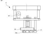
- FIG. 1 is a schematic configuration diagram of an assembly device according to the first embodiment.
- the assembling device 100 includes a robot 3, a robot hand 4 provided at the tip thereof, a control unit 5 for controlling the operation of the robot 3 and the robot hand 4, and the assembling device 100.
- the alignment members 7 and 8 are not particularly limited, but may be alignment pins.
- the control unit 5 may be mounted inside the robot 3, may exist outside the robot 3, and the robot 3 may be remotely controlled from the control unit 5 wirelessly or the like.
- the X and Y directions define the installation surface of the robot 3 or the plane of the stage 6 on which the first component 1 and the second component 2 are installed, and the Z direction is the XY plane. It defines the vertical direction perpendicular to. Further, in the following description, the positive direction of the Z-axis will be referred to as the upper side, and the negative direction will be referred to as the lower side.
- the first component 1 and the second component 2 are components that form a part of the housing of the electronic device, respectively.
- the material of the first component 1 and the second component 2 is not particularly limited, but it is preferably a resin molded product having appropriate elasticity for fitting by snap-fitting.
- FIG. 3 is a schematic cross-sectional view of the parts to be worked on by the assembly device according to the first embodiment before fitting.
- FIG. 4A is a schematic side view of the parts to be worked on by the assembly device according to the first embodiment before fitting
- FIG. 4B is a perspective view of the first part 1.
- the X direction is the depth direction of the first component 1 and the second component 2
- the Y direction is the width direction of the first component 1 and the second component 2
- the Z direction is the first component 1 and the first component 2.
- the two parts 2 coincide with each other in the height direction.
- the first board 11 is provided with the first connector 12.
- the first connector 12 is provided closer to the other than one of the pair of first side wall portions 10 facing each other in the width direction.
- the side far from the first connector 12 is referred to as the first side wall portion 10a
- the side closer to the first connector 12 is referred to as the first side wall portion 10b.
- the first side wall portion 10 it is described as the first side wall portion 10.
- the first side wall portion is shown as 10a, 10, or 10b, 10 in the drawings.
- the parts where similar members are described are expressed in the same manner.
- Two leg portions 13 are provided so as to extend in the height direction on each of the pair of first side wall portions 10 facing the width direction of the first component 1.
- the legs 13 extend to a height comparable to, for example, the opposite surface of the surface fixed to the first substrate 11 of the first connector 12.
- the legs 13 are formed with convex portions 14 projecting outward from the pair of first side wall portions 10.
- the convex portion 14 is provided at, for example, the lower end of the leg portion 13.
- the convex portion 14 preferably has a tapered shape narrowed in the protruding direction.
- the leg portion 13 and the convex portion 14 are described by omitting the hatching indicating the cross section from the viewpoint of easy viewing. The same applies to other drawings.
- the side far from the first connector 12 will be referred to as the leg 13a
- the side closer to the first connector 12 will be referred to as the leg 13b
- the leg 13 will be described.
- the convex portion 14a the side far from the first connector 12
- the convex portion 14b the side closer to the first connector 12
- the convex portion 14 is described.
- the second component 2 has a rectangular parallelepiped main body portion 15 and a second side wall portion 16 that is upright from the outer periphery of the upper surface of the main body portion 15 in the height direction.
- a second substrate 17 is fixedly provided inside the second component 2 surrounded by the second side wall portion 16.
- a second connector 18 is provided on the second substrate 17.
- the second connector 18 is provided closer to the other than one of the pair of second side wall portions 16 facing each other in the width direction.
- the second connector 18 is provided corresponding to the position of the first connector 12 of the first component 1.
- the first connector 12 and the second connector 18 are fitted, and the first component 1 and the second component 2 are electrically connected.
- the pair of second side wall portions 16 facing each other in the width direction of the second component 2 are formed with recesses 19 corresponding to the positions where the legs 13 of the first component 1 are provided.
- the recess 19 is, for example, a through hole penetrating the second side wall portion 16.
- the length from the upper surface of the second side wall portion 16 to the recess 19 is preferably the same as the length of the leg portion 13 in the height direction.
- the convex portion 14 formed on the leg portion 13 of the first component 1 is inserted into the concave portion 19 formed on the second side wall portion 16 of the second component 2 to be fitted by snap-fitting.
- the second side wall portion 16 is described by omitting the hatching showing the cross section from the viewpoint of easy viewing. The same applies to other drawings.
- the side far from the second connector 18 is referred to as the second side wall portion 16a
- the side closer to the second connector 18 is referred to as the second side wall portion 16b. In this case, it is described as the second side wall portion 16.
- the side far from the second connector 18 is described as the recess 19a
- the side closer to the second connector 18 is described as the recess 19b
- the recess 19 is described.
- the positions of the first connector 12 and the second connector 18, the legs 13 and the protrusions are formed.
- the positions of the portion 14 and the recess 19 are configured to coincide with each other in the width direction and the depth direction.
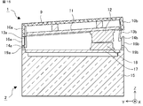
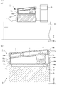
- FIG. 5 is a schematic cross-sectional view of the parts to be worked on by the assembly device according to the first embodiment after fitting.
- the leg portion 13 of the first component 1 is passed through the inside of the second side wall portion 16 of the second component 2.
- the convex portion 14 of the first component 1 is inserted into the concave portion 19 of the second component 2.
- the lower surface of the first side wall portion 10 of the first component 1 and the upper surface of the second side wall portion 16 are in contact with each other.
- the first component 1 When the first component 1 and the second component 2 are fitted together, the first component 1 is placed in the second component 1 while the first substrate 11 of the first component 1 remains parallel to the second substrate 17 of the second component 2.
- the first connector 12 and the second connector 18 interfere with each other before the convex portion 14 of the leg portion 13 is inserted into the concave portion 19, so that the fitting by snap fit cannot be performed. ..
- the first component 1 of the first component 1 is pushed in while the first substrate 11 of the first component 1 is parallel to the second substrate 17 of the second component 2, the first component 1 in the width direction and the depth direction is tried to be pushed. And the second component 2 may be out of alignment with each other.
- the first side wall portion 10a on the side far from the first connector 12 approaches the second side wall portion 16a on the side far from the second connector 18. It is necessary to tilt the first component 1 as described above. Then, the convex portion 14a of the leg portion 13a on the side far from the first connector 12 is inserted into the concave portion 19a of the second component 2. After that, the first connector 12 and the second connector 18 are fitted while returning the inclination of the first component 1 so that the first board 11 is parallel to the second board 17, and from the first connector 12. The convex portion 14b of the leg portion 13b on the near side is inserted into the concave portion 19b of the second component 2.
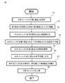
- FIG. 6 is a flowchart illustrating an assembling method using the assembling device according to the first embodiment.
- the first component 1 and the second component 2 are installed, for example, on the stage 6, and are installed at predetermined positions by the alignment members 7 and 8.
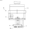
- FIG. 7 is a schematic configuration diagram of a robot hand of the assembly device according to the first embodiment.
- the robot hand 4 includes, for example, a grip portion 20 that grips the first component 1 and a pressing portion 21 that presses the top surface portion 9 of the first component 1.
- the grip portion 20 includes, for example, a suction pad 20a and is connected to the vacuum ejector 22.
- the vacuum ejector 22 performs a suction operation to create a vacuum state between the suction pad 20a and the vacuum ejector 22 and grip the first component 1. It becomes possible to do.
- the vacuum ejector 22 may further include a vacuum confirmation sensor capable of confirming the vacuum pressure.
- the material of the pressing portion 21 is not particularly limited, but is preferably a resin-based material so as not to damage the first component 1.
- the control unit 5 outputs a command to the robot hand 4 to grip the first component 1 (step S1).
- the robot hand 4 moves above the first component 1 in response to a command from the control unit 5.
- the vacuum ejector 22 starts the suction operation.
- the robot hand 4 descends to the position coordinates commanded by the control unit 5.
- the suction pad 20a of the robot hand 4 is in contact with the top surface portion 9 of the first component 1 at the position where the lowering of the robot hand 4 is completed.
- a vacuum is created between the suction pad 20a and the vacuum ejector 22, and the first component 1 is gripped.
- the vacuum state is confirmed by the vacuum confirmation sensor of the vacuum ejector 22.
- a signal is output from the vacuum confirmation sensor to the control unit 5.
- the control unit 5 Upon receiving the output signal, the control unit 5 outputs a command to the robot hand 4 to move the first component 1 to the upper side where the first component 1 is installed while holding the first component 1.
- control unit 5 outputs a command to the robot hand 4 to move the robot hand 4 to the upper side of the second component 2 while holding the first component 1 (step S2).
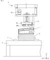
- FIG. 8 is a schematic configuration diagram for explaining the angle of the work object gripped by the robot hand of the assembly device according to the first embodiment.
- the angles commanded by the control unit 5 to the robot hand 4 in step S3 are, for example, the lower surface of the first side wall portion 10a on the side far from the first connector 12 of the first component 1 and the second connector 18 of the second component 2.
- the upper surface of the second side wall portion 16a on the distant side is in contact with the lower surface of the leg portion 13b on the side close to the first connector 12 of the first component 1, and the lower surface of the leg portion 13b on the side closer to the second connector 18 of the second component 2.
- the angle ⁇ 1 formed by the first substrate 11 and the second substrate 17 is set in a state where the upper surface of the two side wall portions 16b is in contact with each other.
- the control unit 5 outputs a command to lower the robot hand 4 from above the second component 2 in a state where the robot hand 4 and the first component 1 gripped by the robot hand 4 are tilted at an angle ⁇ 1 (step S4).
- the leg portion 13a on the side closer to the first connector 12 of the first component 1 is elastically deformed, and the second side wall portion 16a on the side farther from the second connector 18 of the second component 2 is formed. It is passed along the inner surface of the.
- the lower surface of the first side wall portion 10a on the side far from the first connector 12 of the first component 1 and the upper surface of the second side wall portion 16a on the side far from the second connector 18 of the second component 2 come into contact with each other.
- the lower surface of the leg portion 13b on the side close to the first connector 12 of the first component 1 and the upper surface of the second side wall portion 16b close to the second connector 18 of the second component 2 are brought into contact with each other.
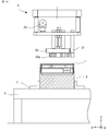
- FIG. 9 is a schematic configuration diagram showing the angles of the work target parts of the assembly device according to the first embodiment.
- the angle formed by the first substrate 11 and the second substrate 17 is smaller at the angle ⁇ 2 after the grip is released than at the angle ⁇ 1 before the grip is released. That is, the relationship is ⁇ 2 ⁇ 1.
- the convex portion 14a formed on the leg portion 13a extending from the first side wall portion 10a on the side far from the first connector 12 becomes the second side wall portion 16a on the side far from the second connector 18. It is inserted into the recess 19a.
- the first component 1 and the second component 2 are positioned in the width direction and the depth direction. As a result, misalignment can be prevented in the assembly steps after step S6 below.
- FIG. 10 is a schematic configuration diagram showing a part of an assembling process using the assembling device according to the first embodiment.
- the control unit 5 issues a command to the robot hand 4 to operate the robot hand 4 so as to take a horizontal state above the second component 2 (step S6).
- FIG. 11 is a schematic configuration diagram showing a part of the assembling process using the assembling device according to the first embodiment.
- the robot hand 4 is lowered again by the command of the control unit 5, and the pressing unit 21 presses the top surface portion 9 of the first component 1 (step S7).
- the first component 1 is pressed by the pressing portion 21 of the robot hand 4 and pressed against the second component 2.
- the contact point between the lower surface of the first side wall portion 10a of the first component 1 and the upper surface of the second side wall portion 16a of the second component 2 is the turning center, and the angle formed by the first substrate 11 and the second substrate 17 is formed. Becomes smaller.
- the leg portion 13b on the side close to the first connector 12 of the first component 1 elastically deforms and bends, while the second component 2 It is passed along the inner side surface of the second side wall portion 16b on the side close to the second connector 18 of the above. Then, the convex portion 14b of the leg portion 13b of the first component 1 is inserted into the concave portion 19b of the second side wall portion 16b of the second component 2, the leg portion 13b elastically returns to the original shape, and the fitting by snap fit is completed. do.
- the top surface portion 9 of the first component 1 is pressed by the pressing portion 21 of the robot hand 4, and the leg portion 13b of the first component 1 is passed along the inner surface of the second side wall portion 16b of the second component 2.
- the first connector 12 of the first component 1 and the second connector 18 of the second component 2 are fitted.
- the first connector 12 and the second connector 18 come into contact with each other to the other end as one end in the width direction comes into contact first and the first substrate 11 of the first component 1 becomes parallel to the second substrate 17 of the second component 2. Then, the fitting is completed (see FIG. 5).
- FIG. 12 is a schematic configuration diagram showing a part of the assembling process using the assembling device according to the first embodiment.
- the control unit 5 lowers the robot hand 4 to a predetermined position, determines that the fitting by the snap fit is completed, and moves the robot hand 4 to the upper side of the first component 1. (Step S8). As a result, the assembly of the first component 1 and the second component 2 is completed.
- step S5 as shown in FIG. 13, when the grip of the first component 1 is released, the leg portion 13a of the first component 1 is separated from the second side wall portion 16a of the second component 2. It is also possible that fitting by snap fit is not possible.
- FIG. 14 is configured so that such a situation does not occur.
- FIG. 14 is a schematic configuration diagram showing another example of the robot hand of the assembly device according to the first embodiment.
- the robot hand 4 preferably includes a first side wall guide 23 that comes into contact with the outer surface of the first side wall portion 10b on the side closer to the first connector 12 of the first component 1.
- the first side wall guide 23 can prevent the leg portion 13a and the convex portion 14a of the first component 1 from being separated from the second side wall portion 16a of the second component 2.
- FIG. 15 is a schematic configuration diagram showing a part of an assembling process using the assembling device according to the first embodiment.
- the convex portion 14b of the leg portion 13b on the side closer to the first connector 12 of the first component 1 is the second side wall portion 16b on the side closer to the second connector 18 of the second component 2.
- a part of the first connector 12 of the first component 1 and a part of the second connector 18 of the second component 2 come into contact with each other.
- the leg portion 13b of the first component 1 undergoes elastic deformation and elastic recovery from the time when a part of the first connector 12 and the second connector 18 comes into contact with each other until the fitting is completed, the first connector 12 and the second connector 12 and the second connector 18 are elastically restored.
- the position relative to the connector 18 may be displaced.
- FIG. 16 is a schematic configuration diagram showing parts that are work targets of the assembly device according to the first embodiment.
- the second connector 18 of the second component 2 has a surface portion 18a which is a surface on the side where the first connector 12 is fitted and a fixing portion 18b fixed to the second substrate 17. Be prepared.
- the external dimensions of the first connector 12 and the second connector 18 are determined in advance. Further, the position of the first connector on the first substrate 11 and the position of the second connector 18 on the second substrate 17 are determined. Further, the dimensions of the first side wall portion 10 of the first component 1, the dimensions of the leg portion 13, and the dimensions of the second side wall portion 16 of the second component 2 are determined.
- FIG. 17 is a schematic diagram for explaining a method of manufacturing an electronic device in which parts are assembled using the assembling device according to the first embodiment.
- the X-axis is the depth direction of the second component 2
- the Y-axis is the width direction of the second component 2
- the Z-axis is the height direction of the second component 2.
- the second component 2 requires a floating amount in the Y-axis direction.
- the first connector 12 and the second connector 18 each have a rectangular parallelepiped shape. Further, it is assumed that the first substrate 11 to which the first connector 12 is fixed and the lower surface of the first side wall portion 10a are in the same plane.
- FIG. 17 the first component first side wall 10a of the lower surface and the pressing portion 21 from a state in which the upper surface and is in contact at the contact point P 1 of the robot hand 4 of the second part 2 of the second side wall portion 16a of one first A state in which the top surface portion 9 of the component 1 is pressed is shown.
- the lower surface and the first component first contact point P 1 becomes the center of the upper surface of the second side wall portion 16a of the first side wall portion 10a is rotated ..
- the first first connector 12 of the component 1 and the second connector 18 of the second part 2 is in contact at the contact point P 2.
- the linear distance from the contact point P 1 between the lower surface and the upper surface of the second side wall portion 16a of the first side wall 10a to the contact point P 2 between the first connector 12 and second connector 18 L Set to 0.
- the horizontal distance from the contact point P 1 between the lower surface and the upper surface of the second side wall portion 16a of the first side wall 10a to the side surface of the first side wall portion 10a of the second connector 18 and L 1.
- the linear distance from the contact point P 1 between the lower surface and the upper surface of the second side wall portion 16a of the first side wall 10a to the side surface of the first side wall portion 10a side of the first connector 12 and L 2.
- the positions of the first connector 12 on the first substrate 11, the positions of the second connector 18 on the second substrate 17, and the external dimensions of the first connector 12 and the second connector 18 are predetermined. That is, L 1 , L 2 , T 1 , and T 2 are known.
- L 3 The floating amount required for the second connector 18 of the second component 2 is calculated by L 3 ⁇ L 1.
- L 3 can be obtained by substituting Eqs. (2) and (3) into Eq. (1).
- L 3 can be calculated from the formula (1) to the formula (3), and the floating amount of the second connector 18 of the second component 2 is calculated by L 3 ⁇ L 1.
- a floating mechanism considering the calculated floating amount is formed between the surface portion 18a and the fixing portion 18b of the second connector 18 of the second component 2.
- the assembling device 100 includes a robot 3, a robot hand 4, and a control unit 5 for controlling them.
- the control unit 5 grips the first component 1 with the gripping unit 20 of the robot hand 4.
- the robot hand 4 is tilted so that one of the pair of first side wall portions 10 of the first component 1 is located below the other.
- the tilted robot hand 4 is lowered until one of the pair of first side wall portions 10 comes into contact with one of the second side wall portions 16 to release the grip of the first component 1, so that the pair of first side wall portions 10 is released.
- the leg portion 13 extending downward from one side is passed through the inside of the pair of second side wall portions 16, and the convex portion 14a protruding outward from the pair of first side wall portions 10 from the leg portion 13a is passed through the pair of second side wall portions. It is inserted into the recess 19a formed on one side of 16. Then, by pressing the first component 1 with the pressing portion 21 of the robot hand 4 so that the first substrate 11 and the second substrate 17 are parallel to each other, the first component 1 extends downward from the other of the pair of first side wall portions 10.
- the leg portion 13a is passed through the inside of the pair of second side wall portions 16, and the convex portion 14b protruding outward from the pair of first side wall portions 10 from the leg portion 13 is formed on the other side of the pair of second side wall portions 16. It is inserted into the recess 19b.
- fitting by a connector and fitting by a snap fit become possible.
- the convex portion 14a formed on the leg portion 13a is inserted into the concave portion 19a formed on one of the pair of second side wall portions 16 and then the first component 1 is pressed by the pressing portion 21, the first component 1 is pressed. It is possible to prevent the relative positions of the 1st component 1 and the 2nd component 2 from shifting.
- one lower surface of a pair of first side wall portions 10 and a pair of first side wall portions 10 are assembled.
- the first connector 12 and the second connector 18 from the horizontal distance from the contact point with the upper surface of one of the two side wall portions 16 to the second connector 18 and the contact point with the upper surface of one of the pair of second side wall portions 16.
- a floating mechanism is formed in the second connector 18 based on the difference from the horizontal distance to the contact point of.
- the assembling device according to the present embodiment further includes a load sensor 24 for detecting the load due to the reaction force from the first component 1 on the robot hand 4b, and the robot hand 4b responds to the load detected by the load sensor 24. Control the descending motion.
- FIG. 18 is a schematic configuration diagram showing a robot hand of the assembly device according to the second embodiment.
- the robot hand 4b includes a load sensor 24 that detects a reaction force.
- the load sensor 24 is, for example, a contact type sensor, in which the pressing portion 21 of the robot hand 4b presses the top surface portion 9 of the first component 1 and the convex portion 14 of the first component 1 fits into the concave portion 19 of the second component 2. It detects the reaction force when it is pushed in.
- FIG. 19 is a flowchart illustrating the assembling method of the present embodiment. The part that overlaps with the description shown in the first embodiment will be omitted as appropriate.
- the control unit 5 outputs a command to the robot hand 4b to grip the first component 1 (FIG. 19, step S1).
- the robot hand 4b moves to the upper part of the first component 1 in response to a command from the control unit 5, and causes the vacuum ejector 22 to start the suction operation.
- the robot hand 4b descends to a predetermined position coordinate in response to a command from the control unit 5.
- the first component 1 is gripped by the suction pad 20a of the grip portion 20 of the robot hand 4b.
- the robot hand 4b moves to the upper part of the second component 2 in response to a command from the control unit 5 (step S2).
- the control unit 5 of the pair of first side wall portions 10 facing each other in the width direction of the first component 1, the lower surface of the first side wall portion 10a on the side farther from the first connector 12 is on the side closer to the first connector 12.
- the robot hand 4b is tilted so as to be located below the lower surface of the first side wall portion 10b. (Step S3).
- the first component 1 is also tilted at the same angle.
- the lower surface of the first side wall portion 10a of the first component 1 and the upper surface of the second side wall portion 16a of the second component 2 are in contact with each other, and the lower surface of the leg portion 13b of the first component 1 and the second component are in contact with each other.
- the lowering operation is performed to a position where the upper surface of the second side wall portion 16b of No. 2 comes into contact with the upper surface (step S4).
- the vacuum ejector 22 of the robot hand 4b stops the suction operation and performs the vacuum breaking operation.
- the suction pad 20a is separated from the top surface portion 9 of the first component 1 to release the grip (step S5).
- the convex portion 14a formed on the leg portion 13a extending from the first side wall portion 10a on the side far from the first connector 12 becomes the second side wall portion 16a on the side far from the second connector 18. It is inserted into the recess 19a.
- the robot hand 4b is returned to a horizontal state above the first component 1 (step S6).
- the robot hand 4b performs a descending operation again (step S7).
- the pressing portion 21 of the robot hand 4b presses the top surface portion 9 of the first component 1 and presses the first component 1 toward the second component 2 (step S7).
- the leg portion 13b of the first component 1 elastically deforms and bends, and inside the second side wall portion 16b of the second component 2. Passed through.
- the load sensor 24 detects the reaction force when the pressing portion 21 of the robot hand 4b presses the first component 1.
- the load sensor 24 has a load at the time of primary insertion due to bending of the leg portion 13b when the leg portion 13b of the first component 1 starts to be passed through the second side wall portion 16b of the second component 2, and when the fitting is completed. Detects the final pushing load of.
- the load at the time of primary insertion bends the leg portion 13b, so that a large load is required. Therefore, the load relationship is that the load at the time of primary insertion> the final pushing load.
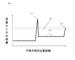
- FIG. 20 is a relationship diagram showing the relationship between the load of the load sensor of the assembly device according to the second embodiment and the position coordinates in the descending direction.
- the vertical axis shows the load of the load sensor
- the horizontal axis shows the position coordinates in the descending direction.
- the load detected by the load sensor 24 is the load F1 when the leg portion 13b of the first component 1 enters the inside of the second side wall portion 16b of the second component 2 and begins to bend.
- the load F2 when the leg portion 13b of the first component 1 is pushed in in a bent state
- the load F3 when the convex portion 14b of the leg portion 13b of the first component 1 is fitted into the concave portion 19b of the second component 2. It is displaced in three stages.
- the load F3 of the load sensor 24 increases.
- the load sensor 24 detects that the detected load is within the range S of the load at the time of fitting completed, which is stored in advance, at the position coordinates where the fitting is completed, and determines the fitting completion (step S9). .. If the load does not fall within the range of the load stored in advance, it may be determined that the fitting is defective and an abnormality may be transmitted to the control unit and the outside (step S10).
- the control unit 5 raises the robot hand 4b after the load at the time of fitting completion is within the range of the load stored in advance, and after it is determined that the fitting is completed, the first component 1 and the second component 2 are fitted. Is completed (step S8).
- the robot hand 4b holding the first component 1 is held by one of the pair of first side wall portions 10 of the first component 1. Tilt so that it is located below, and in the tilted state, lower the first component 1 from above the second component 2, release the grip of the robot hand 4b, and then attach the first component 1 to the second component 2. Press. This enables fitting by a connector and fitting by a snap fit.
- the lowering motion of the robot hand 4b can be controlled according to the load detected by the load sensor 24, and the load on the first component 1 and the second component 2 is reduced. Further, by detecting the load of the reaction force pushed by the load sensor 24, when a load outside the permissible range is detected in the load pushed at the time of primary insertion and the final insertion, the first component 1 and the second component 2 It is possible to determine a fitting defect.
- the floating mechanism described in the first embodiment can also be mounted in the second embodiment.
- the assembling device 100b according to the present embodiment further includes a second side wall guide 25 which is a mechanism for pressing the first side wall portion 10 of the first component 1 on the stage 6, and the first component 1 is provided with the first side wall guide 25. Assembling is performed by pressing from two directions of the Z axis and the Y axis.
- the first component When the dimension 16c between the second side wall portions 16 of the second component 2 is smaller than the dimension 13c between the legs 13 of 1, the pressing portion 21 of the robot hand 4 presses the top surface portion 9 of the first component 1.
- the leg portion 13b of the first component 1 comes into contact with the upper portion of the second side wall portion 16b of the second component 2, and the leg portion 13b of the first component 1 does not elastically deform, making assembly impossible.
- assembling is possible by performing not only the pressing in the Z-axis direction described in the first and second embodiments but also the pressing in the Y-axis direction.
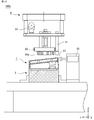
- FIG. 22 is a schematic configuration diagram of the assembly device according to the third embodiment.
- the stage 6 includes a second side wall guide 25 which is a pressing mechanism for pressing the first side wall portion 10 of the first component 1.
- the second side wall guide 25 is, for example, a pneumatic cylinder, and presses the first side wall portion 10 in the Y-axis direction before the pressing portion 21 of the robot hand 4 presses the top surface portion 9 of the first component 1. It is a thing.
- FIG. 23 is a flowchart illustrating the assembling method of the present embodiment. The part that overlaps with the description shown in the first embodiment will be omitted as appropriate.
- the control unit 5 outputs a command to the robot hand 4b to grip the first component 1 (FIG. 6, step S1).
- the robot hand 4b moves to the upper part of the first component 1 in response to a command from the control unit 5, and causes the vacuum ejector 22 to start the suction operation.
- the robot hand 4b descends to a predetermined position coordinate in response to a command from the control unit 5.
- the first component 1 is gripped by the suction pad 20a of the grip portion 20 of the robot hand 4b.
- the robot hand 4b moves to the upper part of the second component 2 in response to a command from the control unit 5 (step S2).
- the control unit 5 of the pair of first side wall portions 10 facing each other in the width direction of the first component 1, the lower surface of the first side wall portion 10a on the side farther from the first connector 12 is on the side closer to the first connector 12.
- the robot hand 4b is tilted so as to be located below the lower surface of the first side wall portion 10b. (Step S3).
- the first component 1 is also tilted at the same angle.
- the lower surface of the first side wall portion 10a of the first component 1 and the upper surface of the second side wall portion 16a of the second component 2 are in contact with each other, and the lower surface of the leg portion 13b of the first component 1 and the second component are in contact with each other.
- the lowering operation is performed to a position where the upper surface of the second side wall portion 16b of No. 2 comes into contact with the upper surface (step S4).
- the vacuum ejector 22 of the robot hand 4b stops the suction operation and performs the vacuum breaking operation.
- the suction pad 20a is separated from the top surface portion 9 of the first component 1 to release the grip (step S5).
- the convex portion 14a formed on the leg portion 13a extending from the first side wall portion 10a on the side far from the first connector 12 becomes the concave portion of the second side wall portion 16a on the side far from the second connector 18. It is inserted in 19a.
- the robot hand 4b is returned to a horizontal state above the first component 1 (step S6).
- the first side wall portion 10b of the first component 1 is pressed in the Y-axis direction by the second side wall guide 25 that presses the first side wall portion 10 provided in the stage 6. (Step S11).
- the leg portion 13a of the first component 1 elastically deforms and bends as shown in FIG. 24 (b), and the second component 2 second. 2 It is pressed inside the side wall portion 16a.
- the first side wall portion 10b of the first component 1 is first pressed in the Y-axis direction, the leg portion 13a of the first component 1 is bent, and the pressing portion 21 of the robot hand 4 is pressed.
- the leg portion 13b of the first component 1 becomes the second side wall portion 16b of the second component 2. It becomes easier to enter.
- the robot hand 4 performs the lowering operation again while pressing the first side wall portion 10b of the first component 1. Then, the pressing portion 21 of the robot hand 4 presses the top surface portion 9 of the first component 1 and presses the first component 1 toward the second component 2 (step S7).
- the robot hand 4b holding the first component 1 is attached to the pair of first side wall portions of the first component 1. Tilt so that one side of 10 is located below the other, and in the tilted state, lower the first part 1 from above the second part 2, release the grip of the robot hand 4b, and then move the first part 1 to the first part. 2 Press against the part 2. This enables fitting by a connector and fitting by a snap fit.
- the assembly can be performed without difficulty. Make it possible.
- the floating mechanism described in the first embodiment can also be mounted in the third embodiment.
- the robot 3 is a 6-axis robot, but a robot having less than 6 axes or a robot having 6 or more axes may be used.
- the robot 3 may be a three-axis orthogonal type robot having orthogonal movements of the X, Y-axis, and Z-axis, and may have a mechanism that allows the hand mounting portion to turn in one axis.
- a robot other than the vertical articulated type such as a horizontal articulated type may be used.
- the robot hands 4 and 4b are provided with the vacuum ejector 22 and the grip portion 20 has the suction pad 20a.
- the first component 1 can be gripped, for example, an air chuck. May be used.
- the robot hand may be provided with several fingers for sandwiching and gripping the first component 1.
- two leg portions 13a are provided on the first side wall portions 10 facing each other of the first component 1, and two legs are provided on the second side wall portions 16 facing each other of the second component 2.
- the leg portion 13 and the recess 19 may be two or more.
Abstract
In the present invention, a first component (1) is grasped by a robot hand (4), and the robot hand (4) is tilted such that one of a pair of first side walls (10) is positioned lower than the other. The tilted robot hand (4) is lowered from above a second component (2) and, after a lower surface of the one of the pair of first side walls (10) contacts an upper surface of one of a pair of second side walls (16), the grasp is released. A protrusion (14a), which protrudes from a leg (13) extending downward from the one of the pair of side walls (10), is inserted into a recess (19b) formed in the one of the pair of second side walls (16). The first component 1 is pressed by the robot hand (4). A protrusion (14b), which protrudes from a leg (13) extending downward from the other of the pair of side walls (10), is inserted into a recess (19b) formed in the other of the pair of second side walls (16).
Description
本開示は、ロボットを用いて部品を組み付ける組付装置、組付方法および電子機器の製造方法に関する。
This disclosure relates to an assembling device for assembling parts using a robot, an assembling method, and a manufacturing method for electronic devices.
従来、電子機器の筐体を構成する2つの部品を嵌合する方式として、スナップフィットが知られている。スナップフィットは、材料の弾性を利用し、一方の部品に設けた凸部を他方の部品の凹部に引っ掛けることにより嵌合する方法である。近年、電子機器の生産性向上を目的として、このようなスナップフィットによる組付作業を、人手によるものからロボットに置き換えることが可能な組付装置の開発が求められている。例えば、特許文献1では、第1部品が第2部品に載せられた状態から押圧部で第1部品を押圧することでスナップフィット部を嵌合させるように構成された部品組み付け装置が開示されている。
Conventionally, snap-fit is known as a method of fitting two parts constituting the housing of an electronic device. Snap-fit is a method of fitting by hooking a convex portion provided on one component on a concave portion of the other component by utilizing the elasticity of the material. In recent years, for the purpose of improving the productivity of electronic devices, there has been a demand for the development of an assembling device capable of replacing such snap-fit assembling work with a robot. For example, Patent Document 1 discloses a component assembling device configured to fit a snap-fit portion by pressing the first component with a pressing portion from a state where the first component is mounted on the second component. There is.
一方、筐体内部に基板が搭載された電子機器の部品では、スナップフィットによる嵌合に加えて、部品同士を電気的に接続するためのコネクタによる嵌合が必要となる。しかしながら、筐体内部にコネクタが設けられた部品の場合、従来の方法では、コネクタが干渉しスナップフィットによる嵌合ができないという課題があった。
On the other hand, for electronic device parts with a board mounted inside the housing, in addition to fitting by snap-fitting, fitting by a connector for electrically connecting the parts is required. However, in the case of a component provided with a connector inside the housing, there is a problem that the conventional method interferes with the connector and cannot be fitted by snap-fitting.
本開示は、上述のような課題を解決するためになされたもので、電子機器の筐体を構成する2つの部品をコネクタにより嵌合するとともにスナップフィットにより嵌合する組付装置、組付方法および電子機器の製造方法を提供することを目的とする。
The present disclosure has been made in order to solve the above-mentioned problems, and is an assembling device and an assembling method in which two parts constituting a housing of an electronic device are fitted by a connector and by snap-fitting. And to provide a method of manufacturing electronic devices.
本開示に係る組付装置は、互いに対向する一対の第1側壁部の一方よりも他方の近くに第1コネクタが第1基板に設けられた第1部品と、第2基板を囲う第2側壁部を有し、互いに対向する一対の第2側壁部の一方よりも他方の近くに第2コネクタが第2基板に設けられた第2部品とを組み付ける組付装置であって、第1部品を把持する把持部および第1部品を押圧する押圧部を有するロボットハンド、ロボットハンドを先端に有するロボット、ロボットハンドおよびロボットを制御する制御部を備え、制御部は、ロボットハンドの把持部で第1部品を把持させ、一対の第1側壁部の一方が他方よりも下方に位置するようにロボットハンドを傾け、傾けたロボットハンドを第2部品の上方から下降させ、一対の第1側壁部の一方の下面が一対の第2側壁部の一方の上面に接触してから把持部の把持を解除させることで、一対の第1側壁部の一方から下方に延びた脚部を一対の第2側壁部の内側に通し、一対の第1側壁部の一方から下方に延びた脚部から一対の第1側壁部の外側に突出した凸部を、一対の第2側壁部の一方に形成された凹部に挿入させ、ロボットハンドの押圧部で第1基板と第2基板とが平行となるように第1部品を押圧させることで、一対の第1側壁部の他方から下方に延びた脚部を一対の第2側壁部の内側に通し、一対の第1側壁部の他方から下方に延びた脚部から一対の第1側壁部の外側に突出した凸部を、一対の第2側壁部の他方に形成された凹部に挿入させる。
The assembling device according to the present disclosure includes a first component in which a first connector is provided on a first substrate closer to the other than one of a pair of first side wall portions facing each other, and a second side wall surrounding the second substrate. An assembling device for assembling a second component having a portion and having a second connector closer to the other than one of a pair of second side wall portions facing each other, wherein the first component is assembled. A robot hand having a grip portion to be gripped and a pressing portion to press the first component, a robot having the robot hand at the tip, a robot hand, and a control unit for controlling the robot are provided, and the control unit is the first grip portion of the robot hand. The parts are gripped, the robot hand is tilted so that one of the pair of first side wall portions is located below the other, and the tilted robot hand is lowered from above the second component, and one of the pair of first side wall portions is used. By releasing the grip of the grip portion after the lower surface of the robot comes into contact with the upper surface of one of the pair of second side wall portions, the leg portion extending downward from one of the pair of first side wall portions is separated from the pair of second side wall portions. A convex portion protruding outward from the pair of first side wall portions from a leg portion extending downward from one of the pair of first side wall portions is formed into a concave portion formed on one of the pair of second side wall portions. By inserting and pressing the first component with the pressing portion of the robot hand so that the first substrate and the second substrate are parallel to each other, a pair of legs extending downward from the other of the pair of first side wall portions are formed. A convex portion is formed on the other side of the pair of second side wall portions so as to pass through the inside of the second side wall portion and project outward from the pair of first side wall portions from the leg portion extending downward from the other of the pair of first side wall portions. Insert it into the recess.
また、本開示に係る組付方法は、第1基板を囲う第1側壁部を有し、互いに対向する一対の第1側壁部の一方よりも他方の近くに第1コネクタが第1基板に設けられた第1部品と、第2基板を囲う第2側壁部を有し、互いに対向する一対の第2側壁部の一方よりも他方の近くに第2コネクタが第2基板に設けられた第2部品とを組み付ける組付方法であって、ロボットハンドの把持部で第1部品を把持させ、一対の第1側壁部の一方が他方よりも下方に位置するようにロボットハンドを傾けるステップ、傾けたロボットハンドを第2部品の上方から下降させ、一対の第1側壁部の一方の下面が一対の第2側壁部の一方の上面に接触してから把持部の把持を解除させることで、一対の第1側壁部の一方から下方に延びた脚部を一対の第2側壁部の内側に通し、一対の第1側壁部の一方から下方に延びた脚部から一対の第1側壁部の外側に突出した凸部を、一対の第2側壁部の一方に形成された凹部に挿入させるステップ、ロボットハンドの押圧部で第1基板と第2基板とが平行となるように第1部品を押圧させることで、一対の第1側壁部の他方から下方に延びた脚部を一対の第2側壁部の内側に通し、一対の第1側壁部の他方から下方に延びた脚部から一対の第1側壁部の外側に突出した凸部を、一対の第2側壁部の他方に形成された凹部に挿入させるステップを備える。
Further, in the assembly method according to the present disclosure, the first side wall portion surrounding the first substrate is provided, and the first connector is provided on the first substrate closer to the other than one of the pair of first side wall portions facing each other. A second component having a first component and a second side wall portion surrounding the second substrate, and a second connector provided on the second substrate closer to the other than one of the pair of second side wall portions facing each other. This is an assembly method for assembling parts, in which the first part is gripped by the grip portion of the robot hand, and the robot hand is tilted so that one of the pair of first side wall portions is located below the other. The robot hand is lowered from above the second component, and the lower surface of one of the pair of first side wall portions comes into contact with the upper surface of one of the pair of second side wall portions, and then the grip of the grip portion is released. A leg portion extending downward from one of the first side wall portions is passed through the inside of the pair of second side wall portions, and a leg portion extending downward from one of the pair of first side wall portions to the outside of the pair of first side wall portions. The step of inserting the protruding convex portion into the concave portion formed on one of the pair of second side wall portions, and the pressing portion of the robot hand presses the first component so that the first substrate and the second substrate are parallel to each other. As a result, the legs extending downward from the other of the pair of first side wall portions are passed through the inside of the pair of second side wall portions, and the pair of first side walls extending downward from the other of the pair of first side wall portions. A step is provided in which a convex portion protruding outward of the side wall portion is inserted into a concave portion formed on the other side of the pair of second side wall portions.
また、本開示に係る電子機器の製造方法は、組付装置を用いて、第1基板を囲う第1側壁部を有し、互いに対向する一対の第1側壁部の一方よりも他方の近くに第1コネクタが第1基板に設けられた第1部品と、第2基板を囲う第2側壁部を有し、互いに対向する一対の第2側壁部の一方よりも他方の近くに第2コネクタが第2基板に設けられた第2部品とが組み付けられる電子機器の製造方法であって、一対の第1側壁部の一方の下面と、一対の第2側壁部の一方との上面とが第1接触点で接触し、第1コネクタと第2コネクタとが第2接触点で接触した状態において、第1接触点から第2コネクタまでの水平距離と、第1接触点から第2接触点までの水平距離との差に基づいて、第2コネクタにフローティング機構を形成する。
Further, the method for manufacturing an electronic device according to the present disclosure uses an assembling device to have a first side wall portion surrounding a first substrate, and is closer to the other than one of the pair of first side wall portions facing each other. The first connector has a first component provided on the first board and a second side wall portion surrounding the second board, and the second connector is closer to the other than one of the pair of second side wall portions facing each other. A method for manufacturing an electronic device to which a second component provided on a second substrate is assembled, wherein a lower surface of one of a pair of first side wall portions and an upper surface of one of a pair of second side wall portions are first. In a state where the first connector and the second connector are in contact with each other at the contact point and the first connector and the second connector are in contact with each other at the second contact point, the horizontal distance from the first contact point to the second connector and the distance from the first contact point to the second contact point. A floating mechanism is formed in the second connector based on the difference from the horizontal distance.
本開示に係る組付装置および組付方法によれば、第1部品を把持したロボットハンドを、第1部品の一対の第1側壁部の一方が他方よりも下方に位置するように傾け、傾けた状態で第2部品の上方から下降してロボットハンドの把持を解除したのち、第1部品を第2部品に対して押圧する。これにより、第1部品と第2部品とをコネクタにより嵌合するとともにスナップフィットにより嵌合することが可能となる。
According to the assembling device and the assembling method according to the present disclosure, the robot hand holding the first component is tilted and tilted so that one of the pair of first side wall portions of the first component is located below the other. In this state, it descends from above the second component to release the grip of the robot hand, and then presses the first component against the second component. As a result, the first component and the second component can be fitted by the connector and by snap fit.
また、本開示に係る電子機器の製造方法によれば、第2コネクタにフローティング機構を形成することで、スナップフィットによる嵌合の過程で、第1コネクタと第2コネクタの相対位置がずれた場合でも第1コネクタおよび第2コネクタの嵌合が可能となる。
Further, according to the method for manufacturing an electronic device according to the present disclosure, when a floating mechanism is formed in the second connector so that the relative positions of the first connector and the second connector deviate in the process of fitting by snap-fitting. However, the first connector and the second connector can be fitted.
実施の形態1.
以下、本願に係る電力制御装置の好適な実施の形態について、図面を参照して説明する。なお、同一内容および相当部については同一符号を配し、その詳しい説明は省略する。以降の実施形態も同様に、同一符号を付した構成について重複した説明は省略する。Embodiment 1.
Hereinafter, preferred embodiments of the power control device according to the present application will be described with reference to the drawings. The same contents and corresponding parts are designated by the same reference numerals, and detailed description thereof will be omitted. Similarly, in the following embodiments, duplicate description of the configurations with the same reference numerals will be omitted.
以下、本願に係る電力制御装置の好適な実施の形態について、図面を参照して説明する。なお、同一内容および相当部については同一符号を配し、その詳しい説明は省略する。以降の実施形態も同様に、同一符号を付した構成について重複した説明は省略する。
Hereinafter, preferred embodiments of the power control device according to the present application will be described with reference to the drawings. The same contents and corresponding parts are designated by the same reference numerals, and detailed description thereof will be omitted. Similarly, in the following embodiments, duplicate description of the configurations with the same reference numerals will be omitted.
組付装置100は、第1部品1を第2部品2に組み付ける。図1は、実施の形態1に係る組付装置の概略構成図である。図1に示すように、組付装置100は、ロボット3と、その先端に設けられたロボットハンド4と、ロボット3およびロボットハンド4の動作を制御する制御部5と、組付装置100は、第1部品1および第2部品2が設置されるステージ6と、第1部品1および第2部品2をそれぞれ予め定められた位置に固定するアライメント部材7、8とをさらに備えてもよい。アライメント部材7、8は、特に限定されないがアライメントピンであってもよい。また、制御部5は、ロボット3内に搭載されていてもよく、ロボット3の外に存在し、制御部5から無線などでロボット3を遠隔操作をしてもよい。
The assembly device 100 assembles the first component 1 to the second component 2. FIG. 1 is a schematic configuration diagram of an assembly device according to the first embodiment. As shown in FIG. 1, the assembling device 100 includes a robot 3, a robot hand 4 provided at the tip thereof, a control unit 5 for controlling the operation of the robot 3 and the robot hand 4, and the assembling device 100. A stage 6 on which the first component 1 and the second component 2 are installed, and alignment members 7 and 8 for fixing the first component 1 and the second component 2 to predetermined positions, respectively, may be further provided. The alignment members 7 and 8 are not particularly limited, but may be alignment pins. Further, the control unit 5 may be mounted inside the robot 3, may exist outside the robot 3, and the robot 3 may be remotely controlled from the control unit 5 wirelessly or the like.
図1および以下に説明する図において、X方向およびY方向は、ロボット3の設置面または第1部品1と第2部品2とが設置されるステージ6の平面を規定し、Z方向はXY面に垂直な鉛直方向を規定している。また以下の説明では、Z軸の正の方向を上、負の方向を下として説明する。
In FIG. 1 and the drawings described below, the X and Y directions define the installation surface of the robot 3 or the plane of the stage 6 on which the first component 1 and the second component 2 are installed, and the Z direction is the XY plane. It defines the vertical direction perpendicular to. Further, in the following description, the positive direction of the Z-axis will be referred to as the upper side, and the negative direction will be referred to as the lower side.
ロボット3は、ロボットハンド4を制御部5により指令された位置座標に移動させる。
ロボット3は、例えば6軸の回転自由度を有する垂直多関節型のロボットである。ロボットハンド4は、第1部品1を把持するために上下動作、または平面動作を行う。ロボット3は、ロボットハンド4を所定の角度に傾けられるように旋回動作を可能としている。 Therobot 3 moves the robot hand 4 to the position coordinates commanded by the control unit 5.
Therobot 3 is, for example, a vertical articulated robot having six degrees of freedom of rotation. The robot hand 4 performs a vertical movement or a plane movement in order to grip the first component 1. The robot 3 enables a turning motion so that the robot hand 4 can be tilted at a predetermined angle.
ロボット3は、例えば6軸の回転自由度を有する垂直多関節型のロボットである。ロボットハンド4は、第1部品1を把持するために上下動作、または平面動作を行う。ロボット3は、ロボットハンド4を所定の角度に傾けられるように旋回動作を可能としている。 The
The
制御部5は、例えばマイクロコントローラ等のコンピュータを備えたロボットコントローラである。制御部5のハードウエア構成の一例を図2に示す。プロセッサ5aと記憶装置5bから構成され、図示していないが、記憶装置5bはランダムアクセスメモリ等の揮発性記憶装置と、フラッシュメモリ等の不揮発性の補助記憶装置とを具備する。また、フラッシュメモリの代わりにハードディスクの補助記憶装置を具備してもよい。プロセッサ5aは、記憶装置5bに入力された基本プログラム等のソフトウエアを読み出して実行することにより、例えばロボット3の各種動作を制御する。この場合、補助記憶装置から揮発性記憶装置を介してプロセッサ5aにプログラムが入力される。また、プロセッサ5aは、演算結果等のデータを記憶装置5bの揮発性記憶装置に出力してもよいし、揮発性記憶装置を介して補助記憶装置にデータを保存してもよい。
The control unit 5 is a robot controller equipped with a computer such as a microcontroller. FIG. 2 shows an example of the hardware configuration of the control unit 5. It is composed of a processor 5a and a storage device 5b, and although not shown, the storage device 5b includes a volatile storage device such as a random access memory and a non-volatile auxiliary storage device such as a flash memory. Further, an auxiliary storage device of a hard disk may be provided instead of the flash memory. The processor 5a controls various operations of the robot 3, for example, by reading and executing software such as a basic program input to the storage device 5b. In this case, the program is input from the auxiliary storage device to the processor 5a via the volatile storage device. Further, the processor 5a may output data such as a calculation result to the volatile storage device of the storage device 5b, or may store the data in the auxiliary storage device via the volatile storage device.
第1部品1および第2部品2は、それぞれ電子機器の筐体の一部を構成する部品である。第1部品1および第2部品2の材質は特に限定されないが、スナップフィットによる嵌合のため、適度に弾性を有する樹脂成型品であると好ましい。図3は、実施の形態1に係る組付装置の作業対象である部品の嵌合前の概略断面図である。図4(a)は、実施の形態1に係る組付装置の作業対象である部品の嵌合前の概略側面図、図4(b)は、第1部品1の斜視図である。図3および図4(a)ではX方向が第1部品1および第2部品2の奥行き方向、Y方向が第1部品1および第2部品2の幅方向、Z方向が第1部品1および第2部品2の高さ方向に一致している。
The first component 1 and the second component 2 are components that form a part of the housing of the electronic device, respectively. The material of the first component 1 and the second component 2 is not particularly limited, but it is preferably a resin molded product having appropriate elasticity for fitting by snap-fitting. FIG. 3 is a schematic cross-sectional view of the parts to be worked on by the assembly device according to the first embodiment before fitting. FIG. 4A is a schematic side view of the parts to be worked on by the assembly device according to the first embodiment before fitting, and FIG. 4B is a perspective view of the first part 1. In FIGS. 3 and 4A, the X direction is the depth direction of the first component 1 and the second component 2, the Y direction is the width direction of the first component 1 and the second component 2, and the Z direction is the first component 1 and the first component 2. The two parts 2 coincide with each other in the height direction.
図3および図4に示すように、第1部品1は、高さ方向からみて長方形状の天面部9と、天面部9の外周から高さ方向に直立した第1側壁部10とを有する。第1部品1の第1側壁部10で囲われた内側には、天面部9と平行かつ高さ方向に間隔をあけて第1基板11が固定して設けられている。第1基板11は、例えば第1側壁部10の下面と同程度の高さ位置に配置されている。
As shown in FIGS. 3 and 4, the first component 1 has a top surface portion 9 that is rectangular when viewed from the height direction, and a first side wall portion 10 that is upright from the outer periphery of the top surface portion 9 in the height direction. The first substrate 11 is fixedly provided inside the first component 1 surrounded by the first side wall portion 10 so as to be parallel to the top surface portion 9 and at intervals in the height direction. The first substrate 11 is arranged at a height similar to, for example, the lower surface of the first side wall portion 10.
第1基板11には、第1コネクタ12が設けられている。第1コネクタ12は、幅方向に対向する一対の第1側壁部10の一方よりも他方の近くに設けられている。以下では、幅方向に対向する一対の第1側壁部10のうち、第1コネクタ12から遠い側を第1側壁部10a、第1コネクタ12に近い側を第1側壁部10bとし、両方を指す場合は第1側壁部10と記載する。なお、第1側壁部10と第1側壁部10aを両方説明する際は、図面において、第1側壁部を、10a,10、または10b,10のように示す。以下同じような部材の説明を行っている箇所は同様に表す。
The first board 11 is provided with the first connector 12. The first connector 12 is provided closer to the other than one of the pair of first side wall portions 10 facing each other in the width direction. In the following, of the pair of first side wall portions 10 facing each other in the width direction, the side far from the first connector 12 is referred to as the first side wall portion 10a, and the side closer to the first connector 12 is referred to as the first side wall portion 10b. In this case, it is described as the first side wall portion 10. When both the first side wall portion 10 and the first side wall portion 10a are described, the first side wall portion is shown as 10a, 10, or 10b, 10 in the drawings. Hereinafter, the parts where similar members are described are expressed in the same manner.
第1部品1の幅方向に対向する一対の第1側壁部10には、それぞれ2つの脚部13が高さ方向に延びて設けられている。脚部13は、例えば第1コネクタ12の第1基板11に固定された面の反対面と同程度となる高さまで延びている。脚部13には、一対の第1側壁部10の外側に突出した凸部14が形成されている。凸部14は、例えば脚部13の下端に設けられている。凸部14は、突出した方向に狭まったテーパー形状となっていることが好ましい。なお、図において、脚部13および凸部14は、見やすさの点から断面を示すハッチングを省略して記載している。他の図面も同様である。
Two leg portions 13 are provided so as to extend in the height direction on each of the pair of first side wall portions 10 facing the width direction of the first component 1. The legs 13 extend to a height comparable to, for example, the opposite surface of the surface fixed to the first substrate 11 of the first connector 12. The legs 13 are formed with convex portions 14 projecting outward from the pair of first side wall portions 10. The convex portion 14 is provided at, for example, the lower end of the leg portion 13. The convex portion 14 preferably has a tapered shape narrowed in the protruding direction. In the figure, the leg portion 13 and the convex portion 14 are described by omitting the hatching indicating the cross section from the viewpoint of easy viewing. The same applies to other drawings.
以下では、幅方向に対向する脚部13のうち、第1コネクタ12から遠い側を脚部13a、第1コネクタ12に近い側を脚部13bとし、両方を指す場合は脚部13と記載する。また、凸部14のうち、第1コネクタ12から遠い側を凸部14a、第1コネクタ12に近い側を凸部14bとし、両方を指す場合は凸部14と記載する。
In the following, among the legs 13 facing in the width direction, the side far from the first connector 12 will be referred to as the leg 13a, the side closer to the first connector 12 will be referred to as the leg 13b, and when both are referred to, the leg 13 will be described. .. Further, among the convex portions 14, the side far from the first connector 12 is referred to as the convex portion 14a, the side closer to the first connector 12 is referred to as the convex portion 14b, and when both are referred to, the convex portion 14 is described.
図3および図4に示すように、第2部品2は、直方体形状の本体部15と、本体部15の上面の外周から高さ方向に直立した第2側壁部16とを有する。第2部品2の第2側壁部16で囲われた内側には、第2基板17が固定して設けられている。第2基板17には、第2コネクタ18が設けられている。第2コネクタ18は、幅方向に対向する一対の第2側壁部16の一方よりも他方の近くに設けられている。第2コネクタ18は、第1部品1の第1コネクタ12の位置に対応して設けられている。第1コネクタ12と第2コネクタ18とが嵌合されて第1部品1と第2部品2とが電気的に接続される。
As shown in FIGS. 3 and 4, the second component 2 has a rectangular parallelepiped main body portion 15 and a second side wall portion 16 that is upright from the outer periphery of the upper surface of the main body portion 15 in the height direction. A second substrate 17 is fixedly provided inside the second component 2 surrounded by the second side wall portion 16. A second connector 18 is provided on the second substrate 17. The second connector 18 is provided closer to the other than one of the pair of second side wall portions 16 facing each other in the width direction. The second connector 18 is provided corresponding to the position of the first connector 12 of the first component 1. The first connector 12 and the second connector 18 are fitted, and the first component 1 and the second component 2 are electrically connected.
第2部品2の幅方向に対向する一対の第2側壁部16には、第1部品1の脚部13が設けられた位置に対応して、凹部19がそれぞれ形成されている。凹部19は、例えば第2側壁部16を貫通する貫通孔である。第2側壁部16の上面から凹部19までの長さは、脚部13の高さ方向の長さと同じであることが好ましい。第1部品1の脚部13に形成された凸部14が、第2部品2の第2側壁部16に形成された凹部19に挿入されることでスナップフィットにより嵌合される。なお、図において、第2側壁部16は、見やすさの点から断面を示すハッチングを省略して記載している。他の図面も同様である。
The pair of second side wall portions 16 facing each other in the width direction of the second component 2 are formed with recesses 19 corresponding to the positions where the legs 13 of the first component 1 are provided. The recess 19 is, for example, a through hole penetrating the second side wall portion 16. The length from the upper surface of the second side wall portion 16 to the recess 19 is preferably the same as the length of the leg portion 13 in the height direction. The convex portion 14 formed on the leg portion 13 of the first component 1 is inserted into the concave portion 19 formed on the second side wall portion 16 of the second component 2 to be fitted by snap-fitting. In the figure, the second side wall portion 16 is described by omitting the hatching showing the cross section from the viewpoint of easy viewing. The same applies to other drawings.
以下では、幅方向に対向する一対の第2側壁部16のうち、第2コネクタ18から遠い側を第2側壁部16a、第2コネクタ18に近い側を第2側壁部16bとし、両方を指す場合は第2側壁部16として記載する。同様に、幅方向に対向する凹部19のうち、第2コネクタ18から遠い側を凹部19a、近い側を凹部19bと記載し、両方を指す場合は凹部19と記載する。
In the following, of the pair of second side wall portions 16 facing each other in the width direction, the side far from the second connector 18 is referred to as the second side wall portion 16a, and the side closer to the second connector 18 is referred to as the second side wall portion 16b. In this case, it is described as the second side wall portion 16. Similarly, among the recesses 19 facing each other in the width direction, the side far from the second connector 18 is described as the recess 19a, the side closer to the second connector 18 is described as the recess 19b, and when both are referred to, the recess 19 is described.
図3および図4に示すように、第1部品1および第2部品2は、高さ方向に重なるように配置されると、第1コネクタ12と第2コネクタ18の位置、脚部13および凸部14と凹部19の位置とが、幅方向および奥行き方向において一致するように構成されている。
As shown in FIGS. 3 and 4, when the first component 1 and the second component 2 are arranged so as to overlap each other in the height direction, the positions of the first connector 12 and the second connector 18, the legs 13 and the protrusions are formed. The positions of the portion 14 and the recess 19 are configured to coincide with each other in the width direction and the depth direction.
図5は、実施の形態1に係る組付装置の作業対象である部品の嵌合後の概略断面図である。図5に示すように、第1部品1と第2部品2との嵌合が完了したときには、第1部品1の脚部13が第2部品2の第2側壁部16の内側に通され、第1部品1の凸部14が第2部品2の凹部19に挿入された状態となる。また、嵌合が完了した状態では、第1部品1の第1側壁部10の下面と、第2側壁部16の上面とが接触した状態となる。
FIG. 5 is a schematic cross-sectional view of the parts to be worked on by the assembly device according to the first embodiment after fitting. As shown in FIG. 5, when the fitting of the first component 1 and the second component 2 is completed, the leg portion 13 of the first component 1 is passed through the inside of the second side wall portion 16 of the second component 2. The convex portion 14 of the first component 1 is inserted into the concave portion 19 of the second component 2. Further, in the state where the fitting is completed, the lower surface of the first side wall portion 10 of the first component 1 and the upper surface of the second side wall portion 16 are in contact with each other.
第1部品1と第2部品2とを嵌合する際、第1部品1の第1基板11が第2部品2の第2基板17に対して平行な状態のまま第1部品1を第2部品2に押し込もうとすると、脚部13の凸部14が凹部19に挿入されるよりも先に、第1コネクタ12と第2コネクタ18とが干渉するため、スナップフィットによる嵌合ができない。また、第1部品1の第1基板11が第2部品2の第2基板17に対して平行な状態なまま第1部品1を押し込もうとすると、幅方向および奥行き方向における第1部品1と第2部品2との相対位置がずれる可能性がある。
When the first component 1 and the second component 2 are fitted together, the first component 1 is placed in the second component 1 while the first substrate 11 of the first component 1 remains parallel to the second substrate 17 of the second component 2. When trying to push it into the component 2, the first connector 12 and the second connector 18 interfere with each other before the convex portion 14 of the leg portion 13 is inserted into the concave portion 19, so that the fitting by snap fit cannot be performed. .. Further, when the first component 1 of the first component 1 is pushed in while the first substrate 11 of the first component 1 is parallel to the second substrate 17 of the second component 2, the first component 1 in the width direction and the depth direction is tried to be pushed. And the second component 2 may be out of alignment with each other.
そのため第1部品1と第2部品2とを嵌合する際には、まず、第1コネクタ12から遠い側の第1側壁部10aが第2コネクタ18から遠い側の第2側壁部16aに近づくように第1部品1を傾ける必要がある。そして、第1コネクタ12から遠い側の脚部13aの凸部14aを第2部品2の凹部19aに挿入する。そのあと、第1基板11が第2基板17に対して平行となるように第1部品1の傾きを戻しながら第1コネクタ12と第2コネクタ18とを嵌合するとともに、第1コネクタ12から近い側の脚部13bの凸部14bを第2部品2の凹部19bに挿入する。
Therefore, when fitting the first component 1 and the second component 2, first, the first side wall portion 10a on the side far from the first connector 12 approaches the second side wall portion 16a on the side far from the second connector 18. It is necessary to tilt the first component 1 as described above. Then, the convex portion 14a of the leg portion 13a on the side far from the first connector 12 is inserted into the concave portion 19a of the second component 2. After that, the first connector 12 and the second connector 18 are fitted while returning the inclination of the first component 1 so that the first board 11 is parallel to the second board 17, and from the first connector 12. The convex portion 14b of the leg portion 13b on the near side is inserted into the concave portion 19b of the second component 2.
次に、組付装置100を用いて第1部品1と第2部品2とを組み付ける方法について説明する。図6は、実施の形態1に係る組付装置を用いた組付方法を説明するフローチャートである。組付作業の開始時、図1に示すように、第1部品1および第2部品2は、例えばステージ6上に設置され、アライメント部材7、8で所定の位置に設置されている。
Next, a method of assembling the first component 1 and the second component 2 using the assembly device 100 will be described. FIG. 6 is a flowchart illustrating an assembling method using the assembling device according to the first embodiment. At the start of the assembling work, as shown in FIG. 1, the first component 1 and the second component 2 are installed, for example, on the stage 6, and are installed at predetermined positions by the alignment members 7 and 8.
図7は、実施の形態1に係る組付装置のロボットハンドの概略構成図である。ロボットハンド4は、例えば、第1部品1を把持する把持部20および第1部品1の天面部9を押圧する押圧部21を備える。把持部20は、例えば吸着パッド20aを備え、真空エジェクタ22と接続されている。第1部品1の天面部9と吸着パッド20aとを接触させた状態で、真空エジェクタ22が吸引動作を行うことで吸着パッド20aと真空エジェクタ22の間が真空状態となり、第1部品1を把持することが可能となる。真空エジェクタ22は、真空圧力を確認することができる真空確認センサをさらに備えてもよい。押圧部21の材質は、特に限定されないが、第1部品1が損傷しないように樹脂系の材質であることが好ましい。
FIG. 7 is a schematic configuration diagram of a robot hand of the assembly device according to the first embodiment. The robot hand 4 includes, for example, a grip portion 20 that grips the first component 1 and a pressing portion 21 that presses the top surface portion 9 of the first component 1. The grip portion 20 includes, for example, a suction pad 20a and is connected to the vacuum ejector 22. When the top surface portion 9 of the first component 1 and the suction pad 20a are in contact with each other, the vacuum ejector 22 performs a suction operation to create a vacuum state between the suction pad 20a and the vacuum ejector 22 and grip the first component 1. It becomes possible to do. The vacuum ejector 22 may further include a vacuum confirmation sensor capable of confirming the vacuum pressure. The material of the pressing portion 21 is not particularly limited, but is preferably a resin-based material so as not to damage the first component 1.
以下では、一例として図7に示すロボットハンド4を用いて第1部品1と第2部品2とを組み付ける組み付け方法について説明する。図6に示すように、まず制御部5は、ロボットハンド4に対し、第1部品1を把持させる指令を出力する(ステップS1)。まず、ロボットハンド4は、制御部5からの指令を受けて第1部品1の上方に移動する。そして、真空エジェクタ22が吸引動作を開始する。ロボットハンド4は、制御部5により指令された位置座標まで下降する。ロボットハンド4の吸着パッド20aはロボットハンド4の下降が完了した位置において、第1部品1の天面部9に接触している。吸着パッド20aと真空エジェクタ22の間が真空状態となり、第1部品1が把持される。
In the following, as an example, an assembling method for assembling the first component 1 and the second component 2 using the robot hand 4 shown in FIG. 7 will be described. As shown in FIG. 6, first, the control unit 5 outputs a command to the robot hand 4 to grip the first component 1 (step S1). First, the robot hand 4 moves above the first component 1 in response to a command from the control unit 5. Then, the vacuum ejector 22 starts the suction operation. The robot hand 4 descends to the position coordinates commanded by the control unit 5. The suction pad 20a of the robot hand 4 is in contact with the top surface portion 9 of the first component 1 at the position where the lowering of the robot hand 4 is completed. A vacuum is created between the suction pad 20a and the vacuum ejector 22, and the first component 1 is gripped.
真空状態は、真空エジェクタ22の真空確認センサで確認する。真空状態が確認されたら、真空確認センサから制御部5に信号を出力する。出力信号を受けた制御部5は、ロボットハンド4に対し、第1部品1を把持した状態で第1部品1が設置されていた上方まで移動させる指令を出力する。
The vacuum state is confirmed by the vacuum confirmation sensor of the vacuum ejector 22. When the vacuum state is confirmed, a signal is output from the vacuum confirmation sensor to the control unit 5. Upon receiving the output signal, the control unit 5 outputs a command to the robot hand 4 to move the first component 1 to the upper side where the first component 1 is installed while holding the first component 1.
次に制御部5は、ロボットハンド4に対し、第1部品1を把持した状態で、第2部品2の上方まで移動させる指令を出力する(ステップS2)。
Next, the control unit 5 outputs a command to the robot hand 4 to move the robot hand 4 to the upper side of the second component 2 while holding the first component 1 (step S2).
次に、制御部5は、第2部品2の上方でロボットハンド4を予め定められた角度傾ける指令を出力する(ステップS3)。すなわち、制御部5は、第1部品1の幅方向に対向する一対の第1側壁部10のうち、第1コネクタ12から遠い側の第1側壁部10aの下面が、第1コネクタ12に近い側の第1側壁部10bの下面よりも下方に位置するようにロボットハンド4を傾ける。すなわち、鉛直方向において第1コネクタ12から遠い側の第1側壁部10aの下面が第2コネクタ18から遠い側の第2側壁部16aの上面に近づくようにロボットハンド4を傾ける。ロボットハンド4の傾きに応じて、把持された第1部品1も同様に傾く。
Next, the control unit 5 outputs a command for tilting the robot hand 4 at a predetermined angle above the second component 2 (step S3). That is, in the control unit 5, of the pair of first side wall portions 10 facing each other in the width direction of the first component 1, the lower surface of the first side wall portion 10a on the side farther from the first connector 12 is closer to the first connector 12. The robot hand 4 is tilted so as to be located below the lower surface of the first side wall portion 10b on the side. That is, the robot hand 4 is tilted so that the lower surface of the first side wall portion 10a on the side farther from the first connector 12 in the vertical direction approaches the upper surface of the second side wall portion 16a on the side farther from the second connector 18. The gripped first component 1 also tilts according to the tilt of the robot hand 4.
図8は、実施の形態1に係る組付装置のロボットハンドで把持された作業対象の角度を説明するための概略構成図である。ステップS3で制御部5がロボットハンド4に指令する角度は、例えば、第1部品1の第1コネクタ12に遠い側の第1側壁部10aの下面と、第2部品2の第2コネクタ18に遠い側の第2側壁部16aの上面とが接触し、かつ第1部品1の第1コネクタ12に近い側の脚部13bの下面と、第2部品2の第2コネクタ18に近い側の第2側壁部16bの上面とが接触した状態において、第1基板11と第2基板17とがなす角度θ1に設定される。
FIG. 8 is a schematic configuration diagram for explaining the angle of the work object gripped by the robot hand of the assembly device according to the first embodiment. The angles commanded by the control unit 5 to the robot hand 4 in step S3 are, for example, the lower surface of the first side wall portion 10a on the side far from the first connector 12 of the first component 1 and the second connector 18 of the second component 2. The upper surface of the second side wall portion 16a on the distant side is in contact with the lower surface of the leg portion 13b on the side close to the first connector 12 of the first component 1, and the lower surface of the leg portion 13b on the side closer to the second connector 18 of the second component 2. The angle θ1 formed by the first substrate 11 and the second substrate 17 is set in a state where the upper surface of the two side wall portions 16b is in contact with each other.
制御部5は、ロボットハンド4およびそれに把持された第1部品1が角度θ1傾いた状態で、ロボットハンド4を第2部品2の上方から下降させる指令を出力する(ステップS4)。第1部品1が下降されるに従い、第1部品1の第1コネクタ12に近い側の脚部13aが弾性変形しながら、第2部品2の第2コネクタ18から遠い側の第2側壁部16aの内側面に沿って通される。
The control unit 5 outputs a command to lower the robot hand 4 from above the second component 2 in a state where the robot hand 4 and the first component 1 gripped by the robot hand 4 are tilted at an angle θ1 (step S4). As the first component 1 is lowered, the leg portion 13a on the side closer to the first connector 12 of the first component 1 is elastically deformed, and the second side wall portion 16a on the side farther from the second connector 18 of the second component 2 is formed. It is passed along the inner surface of the.
ロボットハンド4は、第1部品1の第1コネクタ12から遠い側の第1側壁部10aの下面と、第2部品2の第2コネクタ18から遠い側の第2側壁部16aの上面が接触し、かつ第1部品1の第1コネクタ12に近い側の脚部13bの下面と第2部品2の第2コネクタ18に近い第2側壁部16bの上面とが接触した状態まで下降する。
In the robot hand 4, the lower surface of the first side wall portion 10a on the side far from the first connector 12 of the first component 1 and the upper surface of the second side wall portion 16a on the side far from the second connector 18 of the second component 2 come into contact with each other. In addition, the lower surface of the leg portion 13b on the side close to the first connector 12 of the first component 1 and the upper surface of the second side wall portion 16b close to the second connector 18 of the second component 2 are brought into contact with each other.
制御部5は、ロボットハンド4の下降動作が完了した後、ロボットハンド4の真空エジェクタ22の吸引動作を停止させ、真空破壊動作を行う。これにより、吸着パッド20aは、第1部品1の天面部9から離れて把持が解除される(ステップS5)。図9は、実施の形態1に係る組付装置の作業対象の部品の角度を示す概略構成図である。第1基板11と第2基板17とがなす角度は、把持が解除される前の角度θ1より、把持が解除された後の角度θ2の方が小さくなる。すなわち、θ2<θ1の関係となる
After the lowering operation of the robot hand 4 is completed, the control unit 5 stops the suction operation of the vacuum ejector 22 of the robot hand 4 and performs the vacuum breaking operation. As a result, the suction pad 20a is separated from the top surface portion 9 of the first component 1 and is released from gripping (step S5). FIG. 9 is a schematic configuration diagram showing the angles of the work target parts of the assembly device according to the first embodiment. The angle formed by the first substrate 11 and the second substrate 17 is smaller at the angle θ2 after the grip is released than at the angle θ1 before the grip is released. That is, the relationship is θ2 <θ1.
把持が解除されると、第1コネクタ12から遠い側の第1側壁部10aからの延びた脚部13aに形成された凸部14aが、第2コネクタ18から遠い側の第2側壁部16aの凹部19aに挿入される。これにより、第1部品1と第2部品2は、幅方向および奥行き方向において位置決めされた状態となる。これにより以下のステップS6以降の組み付け工程で位置ずれを防止することができる。
When the grip is released, the convex portion 14a formed on the leg portion 13a extending from the first side wall portion 10a on the side far from the first connector 12 becomes the second side wall portion 16a on the side far from the second connector 18. It is inserted into the recess 19a. As a result, the first component 1 and the second component 2 are positioned in the width direction and the depth direction. As a result, misalignment can be prevented in the assembly steps after step S6 below.
把持を解除したあと、真空エジェクタ22内の真空確認センサが真空状態の解放を制御部5に出力する。図10は、実施の形態1に係る組付装置を用いた組付工程の一部を示す概略構成図である。図10に示すように、制御部5は、ロボットハンド4に第2部品2の上方で水平状態をとるように動作させる指令を出す(ステップS6)。
After releasing the grip, the vacuum confirmation sensor in the vacuum ejector 22 outputs the release of the vacuum state to the control unit 5. FIG. 10 is a schematic configuration diagram showing a part of an assembling process using the assembling device according to the first embodiment. As shown in FIG. 10, the control unit 5 issues a command to the robot hand 4 to operate the robot hand 4 so as to take a horizontal state above the second component 2 (step S6).
図11は、実施の形態1に係る組付装置を用いた組付工程の一部を示す概略構成図である。図11に示すように、ロボットハンド4は、制御部5の指令により再び下降し、押圧部21で第1部品1の天面部9を押圧する(ステップS7)。第1部品1はロボットハンド4の押圧部21で押圧され、第2部品2に押し付けられる。このとき、第1部品1の第1側壁部10aの下面と第2部品2の第2側壁部16aの上面との接触点が旋回中心となり、第1基板11と第2基板17とがなす角度が小さくなる。さらにロボットハンド4の押圧部21で第1部品1の天面部9を押し付けることで、第1部品1の第1コネクタ12に近い側の脚部13bが弾性変形して撓みながら、第2部品2の第2コネクタ18に近い側の第2側壁部16bの内側面に沿って通される。そして第1部品1の脚部13bの凸部14bが第2部品2の第2側壁部16bの凹部19bに挿入され、脚部13bが元の形状に弾性復帰し、スナップフィットによる嵌合が完了する。
FIG. 11 is a schematic configuration diagram showing a part of the assembling process using the assembling device according to the first embodiment. As shown in FIG. 11, the robot hand 4 is lowered again by the command of the control unit 5, and the pressing unit 21 presses the top surface portion 9 of the first component 1 (step S7). The first component 1 is pressed by the pressing portion 21 of the robot hand 4 and pressed against the second component 2. At this time, the contact point between the lower surface of the first side wall portion 10a of the first component 1 and the upper surface of the second side wall portion 16a of the second component 2 is the turning center, and the angle formed by the first substrate 11 and the second substrate 17 is formed. Becomes smaller. Further, by pressing the top surface portion 9 of the first component 1 with the pressing portion 21 of the robot hand 4, the leg portion 13b on the side close to the first connector 12 of the first component 1 elastically deforms and bends, while the second component 2 It is passed along the inner side surface of the second side wall portion 16b on the side close to the second connector 18 of the above. Then, the convex portion 14b of the leg portion 13b of the first component 1 is inserted into the concave portion 19b of the second side wall portion 16b of the second component 2, the leg portion 13b elastically returns to the original shape, and the fitting by snap fit is completed. do.
また、第1部品1の天面部9がロボットハンド4の押圧部21で押し付けられ、第1部品1の脚部13bが第2部品2の第2側壁部16bの内側面に沿って通されている間に、第1部品1の第1コネクタ12と、第2部品2の第2コネクタ18との嵌合が行われる。
第1コネクタ12および第2コネクタ18は、幅方向の一端が先に接触し、第1部品1の第1基板11が第2部品2の第2基板17に平行になるに従い、他端まで接触して嵌合が完了する(図5参照)。 Further, thetop surface portion 9 of the first component 1 is pressed by the pressing portion 21 of the robot hand 4, and the leg portion 13b of the first component 1 is passed along the inner surface of the second side wall portion 16b of the second component 2. During this time, the first connector 12 of the first component 1 and the second connector 18 of the second component 2 are fitted.
Thefirst connector 12 and the second connector 18 come into contact with each other to the other end as one end in the width direction comes into contact first and the first substrate 11 of the first component 1 becomes parallel to the second substrate 17 of the second component 2. Then, the fitting is completed (see FIG. 5).
第1コネクタ12および第2コネクタ18は、幅方向の一端が先に接触し、第1部品1の第1基板11が第2部品2の第2基板17に平行になるに従い、他端まで接触して嵌合が完了する(図5参照)。 Further, the
The
制御部5には、第1部品1の凸部14bと第2部品2の凹部19bとが嵌合する高さ方向の位置座標が設定されている。ロボットハンド4がスナップフィットによる嵌合が完了する位置座標に達すれば、ロボットハンド4の下降動作を停止させる。
The control unit 5 is set with the position coordinates in the height direction in which the convex portion 14b of the first component 1 and the concave portion 19b of the second component 2 are fitted. When the robot hand 4 reaches the position coordinates where the fitting by the snap fit is completed, the lowering operation of the robot hand 4 is stopped.
図12は、実施の形態1に係る組付装置を用いた組付工程の一部を示す概略構成図である。図12に示すように、制御部5は、ロボットハンド4を所定の位置まで下降させたのち、スナップフィットによる嵌合が完了したと判断して、ロボットハンド4を第1部品1の上方まで移動させる(ステップS8)。これにより、第1部品1と第2部品2の組み付けが完了する。
FIG. 12 is a schematic configuration diagram showing a part of the assembling process using the assembling device according to the first embodiment. As shown in FIG. 12, the control unit 5 lowers the robot hand 4 to a predetermined position, determines that the fitting by the snap fit is completed, and moves the robot hand 4 to the upper side of the first component 1. (Step S8). As a result, the assembly of the first component 1 and the second component 2 is completed.
なお、ステップS5の工程において、図13に示すように、第1部品1の把持が解除されたときに、第1部品1の脚部13aが第2部品2の第2側壁部16aから離れ、スナップフィットによる嵌合ができない場合も考えられる。
In the step S5, as shown in FIG. 13, when the grip of the first component 1 is released, the leg portion 13a of the first component 1 is separated from the second side wall portion 16a of the second component 2. It is also possible that fitting by snap fit is not possible.
このようなことが生じないように構成したのが図14である。図14は、実施の形態1に係る組付装置のロボットハンドの別の一例を示す概略構成図である。図14に示すように、ロボットハンド4は、第1部品1の第1コネクタ12から近い側の第1側壁部10bの外側面に接触させる第1の側壁ガイド23を備えることが好ましい。第1の側壁ガイド23により、第1部品1の脚部13aおよび凸部14aが第2部品2の第2側壁部16aから離間するのを防ぐことができる。
FIG. 14 is configured so that such a situation does not occur. FIG. 14 is a schematic configuration diagram showing another example of the robot hand of the assembly device according to the first embodiment. As shown in FIG. 14, the robot hand 4 preferably includes a first side wall guide 23 that comes into contact with the outer surface of the first side wall portion 10b on the side closer to the first connector 12 of the first component 1. The first side wall guide 23 can prevent the leg portion 13a and the convex portion 14a of the first component 1 from being separated from the second side wall portion 16a of the second component 2.
図15は、実施の形態1に係る組付装置を用いた組付工程の一部を示す概略構成図である。ここで、図15に示すように、第1部品1の第1コネクタ12に近い側の脚部13bの凸部14bが第2部品2の第2コネクタ18に近い側の第2側壁部16bの凹部19bに挿入するより前に、第1部品1の第1コネクタ12と第2部品2の第2コネクタ18の一部が接触する。第1コネクタ12および第2コネクタ18の一部が接触してから嵌合が完了するまでに、第1部品1の脚部13bが弾性変形と弾性復帰を行うため、第1コネクタ12と第2コネクタ18との相対位置にずれが生じることがある。第2部品2の第2コネクタ18にフローティング機構を持たせることで、このような位置ずれが生じた場合でも、第1部品1と第2部品2とを嵌合させることができる。
FIG. 15 is a schematic configuration diagram showing a part of an assembling process using the assembling device according to the first embodiment. Here, as shown in FIG. 15, the convex portion 14b of the leg portion 13b on the side closer to the first connector 12 of the first component 1 is the second side wall portion 16b on the side closer to the second connector 18 of the second component 2. Prior to insertion into the recess 19b, a part of the first connector 12 of the first component 1 and a part of the second connector 18 of the second component 2 come into contact with each other. Since the leg portion 13b of the first component 1 undergoes elastic deformation and elastic recovery from the time when a part of the first connector 12 and the second connector 18 comes into contact with each other until the fitting is completed, the first connector 12 and the second connector 12 and the second connector 18 are elastically restored. The position relative to the connector 18 may be displaced. By providing the second connector 18 of the second component 2 with a floating mechanism, the first component 1 and the second component 2 can be fitted even when such a positional deviation occurs.
以下では、組付装置100を用いたスナップフィットによる嵌合で第1コネクタ12と第2コネクタ18とに相対的な位置ずれが生じた場合でも、コネクタ同士を嵌合させることができるように、第2部品2の第2コネクタ18にフローティング機構を設ける工程について説明する。すなわち、本実施の形態に係る組付装置100を用いて第1部品1と第2部品2とが組み付けられる電子機器の製造方法について説明する。図16は、実施の形態1に係る組付装置の作業対象である部品を示す概略構成図である。図16に示すように、第2部品2の第2コネクタ18は、第1コネクタ12と嵌合される側の面である表面部18aと、第2基板17に固定される固定部18bとを備える。
In the following, the connectors can be fitted to each other even if the first connector 12 and the second connector 18 are relative to each other due to the snap-fit fitting using the assembling device 100. A step of providing a floating mechanism on the second connector 18 of the second component 2 will be described. That is, a method of manufacturing an electronic device to which the first component 1 and the second component 2 are assembled by using the assembly device 100 according to the present embodiment will be described. FIG. 16 is a schematic configuration diagram showing parts that are work targets of the assembly device according to the first embodiment. As shown in FIG. 16, the second connector 18 of the second component 2 has a surface portion 18a which is a surface on the side where the first connector 12 is fitted and a fixing portion 18b fixed to the second substrate 17. Be prepared.
第2コネクタ18にフローティング機構を設けるにあたり、予め第1コネクタ12および第2コネクタ18の外形寸法が決定されている。また、第1基板11上における第1コネクタの位置および第2基板17上における第2コネクタ18の位置が決定されている。
また第1部品1の第1側壁部10の寸法、脚部13の寸法および第2部品2の第2側壁部16の寸法が決定されている。 In providing the floating mechanism on thesecond connector 18, the external dimensions of the first connector 12 and the second connector 18 are determined in advance. Further, the position of the first connector on the first substrate 11 and the position of the second connector 18 on the second substrate 17 are determined.
Further, the dimensions of the firstside wall portion 10 of the first component 1, the dimensions of the leg portion 13, and the dimensions of the second side wall portion 16 of the second component 2 are determined.
また第1部品1の第1側壁部10の寸法、脚部13の寸法および第2部品2の第2側壁部16の寸法が決定されている。 In providing the floating mechanism on the
Further, the dimensions of the first
図17は、実施の形態1に係る組付装置を用いて部品が組み付けられる電子機器の製造方法を説明するための模式図である。図17において、X軸は第2部品2の奥行き方向、Y軸は第2部品2の幅方向、Z軸は第2部品2の高さ方向である。第2部品2は、Y軸方向にフローティング量が必要となる。説明を簡単にするため、第1コネクタ12および第2コネクタ18は、それぞれ直方体形状であるとする。また第1コネクタ12が固定される第1基板11と第1側壁部10aの下面とが同一平面にあるとする。
FIG. 17 is a schematic diagram for explaining a method of manufacturing an electronic device in which parts are assembled using the assembling device according to the first embodiment. In FIG. 17, the X-axis is the depth direction of the second component 2, the Y-axis is the width direction of the second component 2, and the Z-axis is the height direction of the second component 2. The second component 2 requires a floating amount in the Y-axis direction. For the sake of simplicity, it is assumed that the first connector 12 and the second connector 18 each have a rectangular parallelepiped shape. Further, it is assumed that the first substrate 11 to which the first connector 12 is fixed and the lower surface of the first side wall portion 10a are in the same plane.
図17では、第1部品1の第1側壁部10aの下面と第2部品2の第2側壁部16aの上面とが接触点P1で接触した状態からロボットハンド4の押圧部21で第1部品1の天面部9を押圧した状態を示している。図17に示すように、第1部品1を押圧させると、第1側壁部10aの下面と第2側壁部16aの上面との接触点P1が中心となって第1部品1が回動する。第1部品1が回動すると、第1部品1の第1コネクタ12と第2部品2の第2コネクタ18とが接触点P2で接触する。
In Figure 17, the first component first side wall 10a of the lower surface and the pressing portion 21 from a state in which the upper surface and is in contact at the contact point P 1 of the robot hand 4 of the second part 2 of the second side wall portion 16a of one first A state in which the top surface portion 9 of the component 1 is pressed is shown. As shown in FIG. 17, when to press the first component 1, the lower surface and the first component first contact point P 1 becomes the center of the upper surface of the second side wall portion 16a of the first side wall portion 10a is rotated .. When the first part 1 is rotated, the first first connector 12 of the component 1 and the second connector 18 of the second part 2 is in contact at the contact point P 2.
図17に示すように、第1側壁部10aの下面と第2側壁部16aの上面との接触点P1から第1コネクタ12と第2コネクタ18との接触点P2までの直線距離をL0とする。また、第1側壁部10aの下面と第2側壁部16aの上面との接触点P1から第2コネクタ18の第1側壁部10a側の側面までの水平距離をL1とする。第1側壁部10aの下面と第2側壁部16aの上面との接触点P1から第1コネクタ12の第1側壁部10a側の側面までの直線距離をL2とする。また、第1側壁部10aの下面と第2側壁部16aの上面との接触点P1から第1コネクタ12と第2コネクタ18の接触点P2までの水平距離をL3とする。
As shown in FIG. 17, the linear distance from the contact point P 1 between the lower surface and the upper surface of the second side wall portion 16a of the first side wall 10a to the contact point P 2 between the first connector 12 and second connector 18 L Set to 0. Further, the horizontal distance from the contact point P 1 between the lower surface and the upper surface of the second side wall portion 16a of the first side wall 10a to the side surface of the first side wall portion 10a of the second connector 18 and L 1. The linear distance from the contact point P 1 between the lower surface and the upper surface of the second side wall portion 16a of the first side wall 10a to the side surface of the first side wall portion 10a side of the first connector 12 and L 2. Further, the lower surface and the horizontal distance from the contact point P 1 and the upper surface of the second side wall portion 16a and the first connector 12 to the contact point P 2 of the second connector 18 of the first side wall 10a and L 3.
第1側壁部10aの下面と第2側壁部16aの上面との接触点P1から第1コネクタ12と第2コネクタ18の接触点P2までの鉛直距離をT1とする。また、第1コネクタ12の第1基板11に固定された面からその反対面までの長さをT2とする。また、第1側壁部10aの下面と第2側壁部16aの上面との接触点P1から第1コネクタ12と第2コネクタ18との接触点P2までの直線と、接触点P1から第2部品2の第2基板17に平行な方向に引いた直線のなす角度をθとする。
The lower surface and the vertical distance from the contact point P 1 and the upper surface of the second side wall portion 16a and the first connector 12 to the contact point P 2 of the second connector 18 of the first side wall 10a and T 1. Further, the length from the surface fixed to the first substrate 11 of the first connector 12 to the opposite surface is T 2 . Further, the lower surface and the straight line from the contact point P 1 and the upper surface of the second side wall portion 16a and the first connector 12 to the contact point P 2 of the second connector 18 of the first side wall 10a, second from the contact point P 1 Let θ be the angle formed by a straight line drawn in a direction parallel to the second substrate 17 of the two components 2.
前述の通り、第1基板11における第1コネクタ12の位置、第2基板17における第2コネクタ18の位置、第1コネクタ12および第2コネクタ18の外形寸法は予め決定されている。すなわち、L1、L2、T1、T2は既知である。
As described above, the positions of the first connector 12 on the first substrate 11, the positions of the second connector 18 on the second substrate 17, and the external dimensions of the first connector 12 and the second connector 18 are predetermined. That is, L 1 , L 2 , T 1 , and T 2 are known.
第2部品2の第2コネクタ18に必要なフローティング量は、L3-L1で算出される。L3は、式(1)に式(2)、式(3)を代入することで求められる。
The floating amount required for the second connector 18 of the second component 2 is calculated by L 3 − L 1. L 3 can be obtained by substituting Eqs. (2) and (3) into Eq. (1).


式(1)から式(3)よりL3を算出することができ、L3-L1で第2部品2の第2コネクタ18のフローティング量が算出される。算出したフローティング量を考慮したフローティング機構を第2部品2の第2コネクタ18の表面部18aと固定部18bの間に形成する。これにより、スナップフィットによる嵌合で第1コネクタ12と第2コネクタ18とに相対的な位置ずれが生じた場合でも、第1コネクタ12と第2コネクタ18を嵌合させることができる。
L 3 can be calculated from the formula (1) to the formula (3), and the floating amount of the second connector 18 of the second component 2 is calculated by L 3 − L 1. A floating mechanism considering the calculated floating amount is formed between the surface portion 18a and the fixing portion 18b of the second connector 18 of the second component 2. As a result, the first connector 12 and the second connector 18 can be fitted even when the first connector 12 and the second connector 18 are relatively misaligned due to the fitting by the snap fit.
上述のとおり、本実施の形態に係る組付装置100では、ロボット3、ロボットハンド4およびそれらを制御する制御部5を備える。制御部5が、ロボットハンド4の把持部20で第1部品1を把持させる。そして第1部品1の一対の第1側壁部10の一方が他方よりも下方に位置するようにロボットハンド4を傾ける。そして傾けたロボットハンド4を一対の第1側壁部10の一方が第2側壁部16の一方に接触するまで下降させて第1部品1の把持を解除させることで、一対の第1側壁部10の一方から下方に延びた脚部13を一対の第2側壁部16の内側に通し、脚部13aから一対の第1側壁部10の外側に突出した凸部14aを、一対の第2側壁部16の一方に形成された凹部19aに挿入させる。
そして、ロボットハンド4の押圧部21で第1基板11と第2基板17とが平行となるように第1部品1を押圧することで、一対の第1側壁部10の他方から下方に延びた脚部13aを一対の第2側壁部16の内側に通し、脚部13から一対の第1側壁部10の外側に突出した凸部14bを、一対の第2側壁部16の他方に形成された凹部19bに挿入させる。このような構成を用いることで、コネクタによる嵌合とスナップフィットによる嵌合とが可能となる。また、脚部13aに形成された凸部14aを一対の第2側壁部16の一方に形成された凹部19aに挿入することで、そのあと押圧部21で第1部品1を押圧しても第1部品1と第2部品2の相対位置がずれることを防止することができる。 As described above, the assemblingdevice 100 according to the present embodiment includes a robot 3, a robot hand 4, and a control unit 5 for controlling them. The control unit 5 grips the first component 1 with the gripping unit 20 of the robot hand 4. Then, the robot hand 4 is tilted so that one of the pair of first side wall portions 10 of the first component 1 is located below the other. Then, the tilted robot hand 4 is lowered until one of the pair of first side wall portions 10 comes into contact with one of the second side wall portions 16 to release the grip of the first component 1, so that the pair of first side wall portions 10 is released. The leg portion 13 extending downward from one side is passed through the inside of the pair of second side wall portions 16, and the convex portion 14a protruding outward from the pair of first side wall portions 10 from the leg portion 13a is passed through the pair of second side wall portions. It is inserted into the recess 19a formed on one side of 16.
Then, by pressing thefirst component 1 with the pressing portion 21 of the robot hand 4 so that the first substrate 11 and the second substrate 17 are parallel to each other, the first component 1 extends downward from the other of the pair of first side wall portions 10. The leg portion 13a is passed through the inside of the pair of second side wall portions 16, and the convex portion 14b protruding outward from the pair of first side wall portions 10 from the leg portion 13 is formed on the other side of the pair of second side wall portions 16. It is inserted into the recess 19b. By using such a configuration, fitting by a connector and fitting by a snap fit become possible. Further, even if the convex portion 14a formed on the leg portion 13a is inserted into the concave portion 19a formed on one of the pair of second side wall portions 16 and then the first component 1 is pressed by the pressing portion 21, the first component 1 is pressed. It is possible to prevent the relative positions of the 1st component 1 and the 2nd component 2 from shifting.
そして、ロボットハンド4の押圧部21で第1基板11と第2基板17とが平行となるように第1部品1を押圧することで、一対の第1側壁部10の他方から下方に延びた脚部13aを一対の第2側壁部16の内側に通し、脚部13から一対の第1側壁部10の外側に突出した凸部14bを、一対の第2側壁部16の他方に形成された凹部19bに挿入させる。このような構成を用いることで、コネクタによる嵌合とスナップフィットによる嵌合とが可能となる。また、脚部13aに形成された凸部14aを一対の第2側壁部16の一方に形成された凹部19aに挿入することで、そのあと押圧部21で第1部品1を押圧しても第1部品1と第2部品2の相対位置がずれることを防止することができる。 As described above, the assembling
Then, by pressing the
また、本実施の形態に係る組付装置100を用いて第1部品1と第2部品2とが組み付ける電子機器の製造方法では、一対の第1側壁部10の一方の下面と、一対の第2側壁部16の一方との上面との接触点から第2コネクタ18までの水平距離と、一対の第2側壁部16の一方との上面との接触点から第1コネクタ12と第2コネクタ18の接触点までの水平距離との差に基づいて第2コネクタ18にフローティング機構を形成する。これにより、スナップフィットによる嵌合の過程で、第1コネクタ12と第2コネクタ18の相対位置がずれた場合でも第1コネクタ12および第2コネクタ18を嵌合させることが可能となる。
Further, in the method for manufacturing an electronic device in which the first component 1 and the second component 2 are assembled using the assembling device 100 according to the present embodiment, one lower surface of a pair of first side wall portions 10 and a pair of first side wall portions 10 are assembled. The first connector 12 and the second connector 18 from the horizontal distance from the contact point with the upper surface of one of the two side wall portions 16 to the second connector 18 and the contact point with the upper surface of one of the pair of second side wall portions 16. A floating mechanism is formed in the second connector 18 based on the difference from the horizontal distance to the contact point of. As a result, even if the relative positions of the first connector 12 and the second connector 18 are displaced in the process of fitting by snap-fitting, the first connector 12 and the second connector 18 can be fitted.
実施の形態2.
次に本開示の実施の形態2について説明する。本実施の形態に係る組付装置は、ロボットハンド4bが第1部品1からの反力による荷重を検知する荷重センサ24をさらに備え、荷重センサ24で検知された荷重に応じてロボットハンド4bの下降動作を制御する。Embodiment 2.
Next, a second embodiment of the present disclosure will be described. The assembling device according to the present embodiment further includes aload sensor 24 for detecting the load due to the reaction force from the first component 1 on the robot hand 4b, and the robot hand 4b responds to the load detected by the load sensor 24. Control the descending motion.
次に本開示の実施の形態2について説明する。本実施の形態に係る組付装置は、ロボットハンド4bが第1部品1からの反力による荷重を検知する荷重センサ24をさらに備え、荷重センサ24で検知された荷重に応じてロボットハンド4bの下降動作を制御する。
Next, a second embodiment of the present disclosure will be described. The assembling device according to the present embodiment further includes a
図18は、実施の形態2に係る組付装置のロボットハンドを示す概略構成図である。図18に示すように、ロボットハンド4bは、反力を検知する荷重センサ24を備える。荷重センサ24は、例えば接触式のセンサであり、ロボットハンド4bの押圧部21が第1部品1の天面部9を押し付けて第1部品1の凸部14が第2部品2の凹部19に嵌り込むときの反力を検知するものである。
FIG. 18 is a schematic configuration diagram showing a robot hand of the assembly device according to the second embodiment. As shown in FIG. 18, the robot hand 4b includes a load sensor 24 that detects a reaction force. The load sensor 24 is, for example, a contact type sensor, in which the pressing portion 21 of the robot hand 4b presses the top surface portion 9 of the first component 1 and the convex portion 14 of the first component 1 fits into the concave portion 19 of the second component 2. It detects the reaction force when it is pushed in.
次に、本実施の形態に係る組付装置を用いて第1部品1と第2部品2とを組み付ける組付方法について説明する。図19は、本実施の形態の組付方法を説明するフローチャートである。実施の形態1に示した説明と重複する部分は適宜省略する。
Next, an assembling method for assembling the first part 1 and the second part 2 using the assembling device according to the present embodiment will be described. FIG. 19 is a flowchart illustrating the assembling method of the present embodiment. The part that overlaps with the description shown in the first embodiment will be omitted as appropriate.
制御部5は、ロボットハンド4bに対し、第1部品1を把持させる指令を出力する(図19、ステップS1)。ロボットハンド4bは、制御部5より指令を受けて第1部品1の上方まで移動し、真空エジェクタ22に吸引動作を開始させる。ロボットハンド4bは、制御部5より指令を受けて所定の位置座標まで下降する。ロボットハンド4bの把持部20の吸着パッド20aにより第1部品1を把持する。
The control unit 5 outputs a command to the robot hand 4b to grip the first component 1 (FIG. 19, step S1). The robot hand 4b moves to the upper part of the first component 1 in response to a command from the control unit 5, and causes the vacuum ejector 22 to start the suction operation. The robot hand 4b descends to a predetermined position coordinate in response to a command from the control unit 5. The first component 1 is gripped by the suction pad 20a of the grip portion 20 of the robot hand 4b.
ロボットハンド4bは、制御部5より指令を受けて第2部品2の上方まで移動する(ステップS2)。制御部5は、第1部品1の幅方向に対向する一対の第1側壁部10のうち、第1コネクタ12から遠い側の第1側壁部10aの下面が、第1コネクタ12に近い側の第1側壁部10bの下面よりも下方に位置するようにロボットハンド4bを傾ける。(ステップS3)。ロボットハンド4bが傾くことで第1部品1も同じ角度に傾く。
The robot hand 4b moves to the upper part of the second component 2 in response to a command from the control unit 5 (step S2). In the control unit 5, of the pair of first side wall portions 10 facing each other in the width direction of the first component 1, the lower surface of the first side wall portion 10a on the side farther from the first connector 12 is on the side closer to the first connector 12. The robot hand 4b is tilted so as to be located below the lower surface of the first side wall portion 10b. (Step S3). When the robot hand 4b is tilted, the first component 1 is also tilted at the same angle.
ロボットハンド4bは、第1部品1の第1側壁部10aの下面と第2部品2の第2側壁部16aの上面とが接触し、かつ第1部品1の脚部13bの下面と第2部品2の第2側壁部16bの上面とが接触する位置まで下降動作を行う(ステップS4)。
In the robot hand 4b, the lower surface of the first side wall portion 10a of the first component 1 and the upper surface of the second side wall portion 16a of the second component 2 are in contact with each other, and the lower surface of the leg portion 13b of the first component 1 and the second component are in contact with each other. The lowering operation is performed to a position where the upper surface of the second side wall portion 16b of No. 2 comes into contact with the upper surface (step S4).
次にロボットハンド4bの真空エジェクタ22は吸引動作を停止し、真空破壊動作を行う。吸着パッド20aは第1部品1の天面部9から離れて把持を解除する(ステップS5)。把持が解除されると、第1コネクタ12から遠い側の第1側壁部10aからの延びた脚部13aに形成された凸部14aが、第2コネクタ18から遠い側の第2側壁部16aの凹部19aに挿入される。ロボットハンド4bを第1部品1の上方で水平な状態に戻す(ステップS6)。ロボットハンド4bは再び下降動作を行う(ステップS7)。ロボットハンド4bの押圧部21で第1部品1の天面部9を押圧し、第1部品1を第2部品2に向かって押し付ける(ステップS7)。
Next, the vacuum ejector 22 of the robot hand 4b stops the suction operation and performs the vacuum breaking operation. The suction pad 20a is separated from the top surface portion 9 of the first component 1 to release the grip (step S5). When the grip is released, the convex portion 14a formed on the leg portion 13a extending from the first side wall portion 10a on the side far from the first connector 12 becomes the second side wall portion 16a on the side far from the second connector 18. It is inserted into the recess 19a. The robot hand 4b is returned to a horizontal state above the first component 1 (step S6). The robot hand 4b performs a descending operation again (step S7). The pressing portion 21 of the robot hand 4b presses the top surface portion 9 of the first component 1 and presses the first component 1 toward the second component 2 (step S7).
ロボットハンド4bの押圧部21が第1部品1の天面部9を押圧する過程で、第1部品1の脚部13bは弾性変形して撓み、第2部品2の第2側壁部16bの内側に通される。
In the process of the pressing portion 21 of the robot hand 4b pressing the top surface portion 9 of the first component 1, the leg portion 13b of the first component 1 elastically deforms and bends, and inside the second side wall portion 16b of the second component 2. Passed through.
本実施の形態では、荷重センサ24でロボットハンド4bの押圧部21が第1部品1を押し付けたときの反力を検知する。荷重センサ24は、第1部品1の脚部13bが第2部品2の第2側壁部16bに通され始めたときの脚部13bの撓みによる一次挿入時の荷重と、嵌合が完了したときの最終押し込み荷重とを検知する。一次挿入時の荷重は、脚部13bを撓ませるため、大きな荷重が必要となる。そのため、荷重の関係は、一次挿入時の荷重>最終押し込み荷重となる。
In the present embodiment, the load sensor 24 detects the reaction force when the pressing portion 21 of the robot hand 4b presses the first component 1. The load sensor 24 has a load at the time of primary insertion due to bending of the leg portion 13b when the leg portion 13b of the first component 1 starts to be passed through the second side wall portion 16b of the second component 2, and when the fitting is completed. Detects the final pushing load of. The load at the time of primary insertion bends the leg portion 13b, so that a large load is required. Therefore, the load relationship is that the load at the time of primary insertion> the final pushing load.
図20は、実施の形態2に係る組付装置の荷重センサの荷重と下降方向の位置座標の関係を示した関係図である。図19において縦軸が荷重センサの荷重、横軸が下降方向の位置座標を示す。図20に示すように、荷重センサ24によって検知される荷重は、第1部品1の脚部13bが第2部品2の第2側壁部16bの内側に入り込み、撓み始めたときの荷重F1、第1部品1の脚部13bが撓んだ状態で押し込んでいるときの荷重F2、第1部品1の脚部13bの凸部14bが、第2部品2の凹部19bに嵌り込んだときの荷重F3の三段階に変位する。
FIG. 20 is a relationship diagram showing the relationship between the load of the load sensor of the assembly device according to the second embodiment and the position coordinates in the descending direction. In FIG. 19, the vertical axis shows the load of the load sensor, and the horizontal axis shows the position coordinates in the descending direction. As shown in FIG. 20, the load detected by the load sensor 24 is the load F1 when the leg portion 13b of the first component 1 enters the inside of the second side wall portion 16b of the second component 2 and begins to bend. The load F2 when the leg portion 13b of the first component 1 is pushed in in a bent state, and the load F3 when the convex portion 14b of the leg portion 13b of the first component 1 is fitted into the concave portion 19b of the second component 2. It is displaced in three stages.
凸部14bが凹部19bに嵌まり込んだときは、第1部品1と第2部品2との組み付けが完了し、第1側壁部10の下面と第2側壁部16の上面が接触した状態のまま、ロボットハンド4bの押圧部21で押し込んでいるため、荷重センサ24の荷重F3が増す。荷重センサ24は、嵌合が完了した位置座標において、検知された荷重が予め記憶された嵌合完了時の荷重の範囲内Sであることを検出して嵌合完了を判断する(ステップS9)。予め記憶された荷重の範囲内に入らないときは、嵌合不良と判断して制御部および外部
に異常を送信してもよい(ステップS10)。 When theconvex portion 14b is fitted into the concave portion 19b, the assembly of the first component 1 and the second component 2 is completed, and the lower surface of the first side wall portion 10 and the upper surface of the second side wall portion 16 are in contact with each other. Since the robot hand 4b is pushed by the pressing portion 21 as it is, the load F3 of the load sensor 24 increases. The load sensor 24 detects that the detected load is within the range S of the load at the time of fitting completed, which is stored in advance, at the position coordinates where the fitting is completed, and determines the fitting completion (step S9). .. If the load does not fall within the range of the load stored in advance, it may be determined that the fitting is defective and an abnormality may be transmitted to the control unit and the outside (step S10).
に異常を送信してもよい(ステップS10)。 When the
制御部5は、嵌合完了時の荷重が予め記憶された荷重の範囲内であり、嵌合完了と判断されてからロボットハンド4bを上昇させ、第1部品1と第2部品2の嵌合が完了する(ステップS8)。
The control unit 5 raises the robot hand 4b after the load at the time of fitting completion is within the range of the load stored in advance, and after it is determined that the fitting is completed, the first component 1 and the second component 2 are fitted. Is completed (step S8).
上述の通り、本実施の形態に係る組付装置においては、実施の形態1同様、第1部品1を把持したロボットハンド4bを、第1部品1の一対の第1側壁部10の一方が他方よりも下方に位置するように傾け、傾けた状態で第1部品1を第2部品2の上方から下降し、ロボットハンド4bの把持を解除したのち、第1部品1を第2部品2に対して押圧する。これにより、コネクタによる嵌合とスナップフィットによる嵌合とが可能となる。
As described above, in the assembling device according to the present embodiment, as in the first embodiment, the robot hand 4b holding the first component 1 is held by one of the pair of first side wall portions 10 of the first component 1. Tilt so that it is located below, and in the tilted state, lower the first component 1 from above the second component 2, release the grip of the robot hand 4b, and then attach the first component 1 to the second component 2. Press. This enables fitting by a connector and fitting by a snap fit.
さらに本実施の形態では、荷重センサ24で検知された荷重に応じてロボットハンド4bの下降動作を制御することができ、第1部品1および第2部品2に対する負荷が軽減される。また、荷重センサ24で押し込んだ反力の荷重を検知することで、一次挿入時と最終時に押し込む荷重において、許容範囲外の荷重が検知されたときに、第1部品1および第2部品2の嵌合不良を判別することが可能となる。
Further, in the present embodiment, the lowering motion of the robot hand 4b can be controlled according to the load detected by the load sensor 24, and the load on the first component 1 and the second component 2 is reduced. Further, by detecting the load of the reaction force pushed by the load sensor 24, when a load outside the permissible range is detected in the load pushed at the time of primary insertion and the final insertion, the first component 1 and the second component 2 It is possible to determine a fitting defect.
なお、実施の形態1で説明したフローティング機構は、実施の形態2でも搭載可能である。
The floating mechanism described in the first embodiment can also be mounted in the second embodiment.
実施の形態3.
次に本開示の実施の形態3について説明する。本実施の形態に係る組付装置100bは、ステージ6の上に、第1部品1の第1側壁部10を押圧する機構である第2の側壁ガイド25をさらに備え、第1部品1を、Z軸とY軸の2方向から押圧して組付を行うものである。Embodiment 3.
Next, a third embodiment of the present disclosure will be described. The assemblingdevice 100b according to the present embodiment further includes a second side wall guide 25 which is a mechanism for pressing the first side wall portion 10 of the first component 1 on the stage 6, and the first component 1 is provided with the first side wall guide 25. Assembling is performed by pressing from two directions of the Z axis and the Y axis.
次に本開示の実施の形態3について説明する。本実施の形態に係る組付装置100bは、ステージ6の上に、第1部品1の第1側壁部10を押圧する機構である第2の側壁ガイド25をさらに備え、第1部品1を、Z軸とY軸の2方向から押圧して組付を行うものである。
Next, a third embodiment of the present disclosure will be described. The assembling
例えば、図21に示すように、第1部品1の脚部13の間の寸法13cと第2部品2の第2側壁部16の間の寸法16cの嵌め合い寸法の関係性において、第1部品1の脚部13の間の寸法13cに対して、第2部品2の第2側壁部16の間の寸法16cが小さい場合、ロボットハンド4の押圧部21で第1部品1の天面部9を押圧するときに、第1部品1の脚部13bが第2部品2の第2側壁部16bの上部に接触し、第1部品1の脚部13bが弾性変形せず、組付け不可能となることがある。このような場合に、実施の形態1、2で説明したZ軸方向による押圧だけでなく、Y軸方向による押圧を合わせて行うことで組付を可能とする。
For example, as shown in FIG. 21, in the relationship between the fitting dimension of the dimension 13c between the legs 13 of the first component 1 and the dimension 16c between the second side wall portion 16 of the second component 2, the first component When the dimension 16c between the second side wall portions 16 of the second component 2 is smaller than the dimension 13c between the legs 13 of 1, the pressing portion 21 of the robot hand 4 presses the top surface portion 9 of the first component 1. When pressed, the leg portion 13b of the first component 1 comes into contact with the upper portion of the second side wall portion 16b of the second component 2, and the leg portion 13b of the first component 1 does not elastically deform, making assembly impossible. Sometimes. In such a case, assembling is possible by performing not only the pressing in the Z-axis direction described in the first and second embodiments but also the pressing in the Y-axis direction.
図22は実施の形態3に係る組付装置の概略構成図である。図22に示すようにステージ6は第1部品1の第1側壁部10を押圧する押圧機構である第2の側壁ガイド25を備える。第2の側壁ガイド25は、例えば、空圧式のシリンダーであり、ロボットハンド4の押圧部21が第1部品1の天面部9を押し付ける前に、第1側壁部10をY軸方向に押圧するものである。
FIG. 22 is a schematic configuration diagram of the assembly device according to the third embodiment. As shown in FIG. 22, the stage 6 includes a second side wall guide 25 which is a pressing mechanism for pressing the first side wall portion 10 of the first component 1. The second side wall guide 25 is, for example, a pneumatic cylinder, and presses the first side wall portion 10 in the Y-axis direction before the pressing portion 21 of the robot hand 4 presses the top surface portion 9 of the first component 1. It is a thing.
次に、本実施の形態に係る組付装置100bを用いて第1部品1と第2部品2を組み付ける組付方法について説明する。図23は、本実施の形態の組付方法を説明するフローチャートである。実施の形態1に示した説明と重複する部分は適宜省略する。
Next, an assembling method for assembling the first part 1 and the second part 2 using the assembling device 100b according to the present embodiment will be described. FIG. 23 is a flowchart illustrating the assembling method of the present embodiment. The part that overlaps with the description shown in the first embodiment will be omitted as appropriate.
制御部5は、ロボットハンド4bに対し、第1部品1を把持させる指令を出力する(図6、ステップS1)。ロボットハンド4bは、制御部5より指令を受けて第1部品1の上方まで移動し、真空エジェクタ22に吸引動作を開始させる。ロボットハンド4bは、制御部5より指令を受けて所定の位置座標まで下降する。ロボットハンド4bの把持部20の吸着パッド20aにより第1部品1を把持する。
The control unit 5 outputs a command to the robot hand 4b to grip the first component 1 (FIG. 6, step S1). The robot hand 4b moves to the upper part of the first component 1 in response to a command from the control unit 5, and causes the vacuum ejector 22 to start the suction operation. The robot hand 4b descends to a predetermined position coordinate in response to a command from the control unit 5. The first component 1 is gripped by the suction pad 20a of the grip portion 20 of the robot hand 4b.
ロボットハンド4bは、制御部5より指令を受けて第2部品2の上方まで移動する(ステップS2)。制御部5は、第1部品1の幅方向に対向する一対の第1側壁部10のうち、第1コネクタ12から遠い側の第1側壁部10aの下面が、第1コネクタ12に近い側の第1側壁部10bの下面よりも下方に位置するようにロボットハンド4bを傾ける。(ステップS3)。ロボットハンド4bが傾くことで第1部品1も同じ角度に傾く。
The robot hand 4b moves to the upper part of the second component 2 in response to a command from the control unit 5 (step S2). In the control unit 5, of the pair of first side wall portions 10 facing each other in the width direction of the first component 1, the lower surface of the first side wall portion 10a on the side farther from the first connector 12 is on the side closer to the first connector 12. The robot hand 4b is tilted so as to be located below the lower surface of the first side wall portion 10b. (Step S3). When the robot hand 4b is tilted, the first component 1 is also tilted at the same angle.
ロボットハンド4bは、第1部品1の第1側壁部10aの下面と第2部品2の第2側壁部16aの上面とが接触し、かつ第1部品1の脚部13bの下面と第2部品2の第2側壁部16bの上面とが接触する位置まで下降動作を行う(ステップS4)。
In the robot hand 4b, the lower surface of the first side wall portion 10a of the first component 1 and the upper surface of the second side wall portion 16a of the second component 2 are in contact with each other, and the lower surface of the leg portion 13b of the first component 1 and the second component are in contact with each other. The lowering operation is performed to a position where the upper surface of the second side wall portion 16b of No. 2 comes into contact with the upper surface (step S4).
次にロボットハンド4bの真空エジェクタ22は吸引動作を停止し、真空破壊動作を行う。吸着パッド20aは第1部品1の天面部9から離れて把持を解除する(ステップS5)。把持が解除されると、第1コネクタ12から遠い側の第1側壁部10aから延びた脚部13aに形成された凸部14aが、第2コネクタ18から遠い側の第2側壁部16aの凹部19aに挿入される。ロボットハンド4bを第1部品1の上方で水平な状態に戻す(ステップS6)。
Next, the vacuum ejector 22 of the robot hand 4b stops the suction operation and performs the vacuum breaking operation. The suction pad 20a is separated from the top surface portion 9 of the first component 1 to release the grip (step S5). When the grip is released, the convex portion 14a formed on the leg portion 13a extending from the first side wall portion 10a on the side far from the first connector 12 becomes the concave portion of the second side wall portion 16a on the side far from the second connector 18. It is inserted in 19a. The robot hand 4b is returned to a horizontal state above the first component 1 (step S6).
次に、図24(a)に示すように、ステージ6に備える第1側壁部10を押圧する第2の側壁ガイド25により、第1部品1の第1側壁部10bをY軸方向に押圧する(ステップS11)。第1部品1の第1側壁部10bをY軸方向に押圧する過程で、図24(b)に示すように第1部品1の脚部13aは弾性変形して撓み、第2部品2の第2側壁部16aの内側に押し付けられる。
Next, as shown in FIG. 24A, the first side wall portion 10b of the first component 1 is pressed in the Y-axis direction by the second side wall guide 25 that presses the first side wall portion 10 provided in the stage 6. (Step S11). In the process of pressing the first side wall portion 10b of the first component 1 in the Y-axis direction, the leg portion 13a of the first component 1 elastically deforms and bends as shown in FIG. 24 (b), and the second component 2 second. 2 It is pressed inside the side wall portion 16a.
すなわち、図24(b)において、先に第1部品1の第1側壁部10bをY軸方向に押圧し、第1部品1の脚部13aを撓ませて、ロボットハンド4の押圧部21が第1部品1の天面部9を押圧するときに第1部品1の脚部13bを弾性変形し易くすることで、第1部品1の脚部13bは第2部品2の第2側壁部16bに入り込み易くなる。
That is, in FIG. 24B, the first side wall portion 10b of the first component 1 is first pressed in the Y-axis direction, the leg portion 13a of the first component 1 is bent, and the pressing portion 21 of the robot hand 4 is pressed. By making it easy for the leg portion 13b of the first component 1 to be elastically deformed when the top surface portion 9 of the first component 1 is pressed, the leg portion 13b of the first component 1 becomes the second side wall portion 16b of the second component 2. It becomes easier to enter.
第1部品1の第1側壁部10bを押圧した状態でロボットハンド4は再び下降動作を行う。そして、ロボットハンド4の押圧部21で第1部品1の天面部9を押圧し、第1部品1を第2部品2に向かって押し付ける(ステップS7)。
The robot hand 4 performs the lowering operation again while pressing the first side wall portion 10b of the first component 1. Then, the pressing portion 21 of the robot hand 4 presses the top surface portion 9 of the first component 1 and presses the first component 1 toward the second component 2 (step S7).
上述の通り、本実施の形態に係る組付装置においては、実施の形態1および実施の形態2同様、第1部品1を把持したロボットハンド4bを、第1部品1の一対の第1側壁部10の一方が他方よりも下方に位置するように傾け、傾けた状態で第1部品1を第2部品2の上方から下降し、ロボットハンド4bの把持を解除したのち、第1部品1を第2部品2に対して押圧する。これにより、コネクタによる嵌合とスナップフィットによる嵌合とが可能となる。
As described above, in the assembling device according to the present embodiment, as in the first and second embodiments, the robot hand 4b holding the first component 1 is attached to the pair of first side wall portions of the first component 1. Tilt so that one side of 10 is located below the other, and in the tilted state, lower the first part 1 from above the second part 2, release the grip of the robot hand 4b, and then move the first part 1 to the first part. 2 Press against the part 2. This enables fitting by a connector and fitting by a snap fit.
さらに、本実施の形態では、第1部品1の脚部13の間の寸法13cに対して、第2部品2の第2側壁部16の間の寸法16cが小さい場合でも、無理なく組付けを可能とする。
Further, in the present embodiment, even if the dimension 16c between the second side wall portions 16 of the second component 2 is smaller than the dimension 13c between the legs 13 of the first component 1, the assembly can be performed without difficulty. Make it possible.
なお、実施の形態1で説明したフローティング機構は、実施の形態3でも搭載可能である。
The floating mechanism described in the first embodiment can also be mounted in the third embodiment.
実施の形態1から3では、ロボット3が6軸のロボットである例を示したが、6軸より少ない軸のロボットでもよいし6軸以上のロボットとしてもよい。例えばロボット3は、X、Y軸、Z軸の直行動作を有する3軸直行型のロボットで、ハンド取付け部が1軸旋回可能とする機構であってもよい。また例えば水平多関節型等、垂直多関節型以外のロボットとしてもよい。
In the first to third embodiments, the robot 3 is a 6-axis robot, but a robot having less than 6 axes or a robot having 6 or more axes may be used. For example, the robot 3 may be a three-axis orthogonal type robot having orthogonal movements of the X, Y-axis, and Z-axis, and may have a mechanism that allows the hand mounting portion to turn in one axis. Further, a robot other than the vertical articulated type such as a horizontal articulated type may be used.
また、実施の形態1から3では、ロボットハンド4、4bが真空エジェクタ22を備え、把持部20が吸着パッド20aを有する例を示したが、第1部品1を把持できればよく、例えば、エアチャックを用いてもよい。また第1部品1を挟んで把持する数本の指部を備えるロボットハンドであってもよい。
Further, in the first to third embodiments, the robot hands 4 and 4b are provided with the vacuum ejector 22 and the grip portion 20 has the suction pad 20a. However, it suffices if the first component 1 can be gripped, for example, an air chuck. May be used. Further, the robot hand may be provided with several fingers for sandwiching and gripping the first component 1.
また、実施の形態1から3では、第1部品1の互いに対向する第1側壁部10にそれぞれ2つの脚部13aを備え、第2部品2の互いに対向する第2側壁部16にそれぞれ2つの凹部19を備える例を示したが、脚部13、凹部19は2つ以上であってもよい。
Further, in the first to third embodiments, two leg portions 13a are provided on the first side wall portions 10 facing each other of the first component 1, and two legs are provided on the second side wall portions 16 facing each other of the second component 2. Although an example including the recess 19 is shown, the leg portion 13 and the recess 19 may be two or more.
本開示は、様々な例示的な実施の形態及び実施例が記載されているが、1つ、または複数の実施の形態に記載された様々な特徴、態様、及び機能は特定の実施の形態の適用に限られるのではなく、単独で、または様々な組み合わせで実施の形態に適用可能である。
従って、例示されていない無数の変形例が、本願明細書に開示される技術の範囲内において想定される。例えば、少なくとも1つの構成要素を変形する場合、追加する場合または省略する場合、さらには、少なくとも1つの構成要素を抽出し、他の実施の形態の構成要素と組み合わせる場合が含まれるものとする。 Although the present disclosure describes various exemplary embodiments and examples, the various features, embodiments, and functions described in one or more embodiments are those of a particular embodiment. It is not limited to application, but can be applied to embodiments alone or in various combinations.
Therefore, innumerable variations not illustrated are envisioned within the scope of the techniques disclosed herein. For example, it is assumed that at least one component is modified, added or omitted, and further, at least one component is extracted and combined with the components of other embodiments.
1:第1部品、2:第2部品、3:ロボット、4、4b:ロボットハンド、5:制御部、6:ステージ、7、8:アライメント部材、9:天面部、10、10a、10b:第1側壁部、11:第1基板、12:第1コネクタ、13、13a、13b:脚部、14、14a、14b:凸部、15:本体部、16、16a、16b:第2側壁部、17:第2基板、18:第2コネクタ、19、19a、19b:凹部、20:把持部、20a:吸着パッド、21:押圧部、22:真空エジェクタ、23:第1の側壁ガイド、24:荷重センサ、25:第2の側壁ガイド。
1: 1st part, 2: 2nd part, 3: Robot, 4, 4b: Robot hand, 5: Control unit, 6: Stage, 7, 8: Alignment member, 9: Top surface part, 10, 10a, 10b: 1st side wall, 11: 1st substrate, 12: 1st connector, 13, 13a, 13b: legs, 14, 14a, 14b: convex, 15: main body, 16, 16a, 16b: 2nd side wall , 17: 2nd substrate, 18: 2nd connector, 19, 19a, 19b: recess, 20: gripping part, 20a: suction pad, 21: pressing part, 22: vacuum ejector, 23: first side wall guide, 24 : Load sensor, 25: Second side wall guide.
Claims (8)
- 互いに対向する一対の第1側壁部の一方よりも他方の近くに第1コネクタが第1基板に設けられた第1部品と、第2基板を囲う第2側壁部を有し、互いに対向する一対の前記第2側壁部の一方よりも他方の近くに第2コネクタが前記第2基板に設けられた第2部品と、を組み付ける組付装置であって、
前記第1部品を把持する把持部および前記第1部品を押圧する押圧部を有するロボットハンド、
前記ロボットハンドを先端に有するロボット、
前記ロボットハンドおよび前記ロボットを制御する制御部を備え、
前記制御部は、
前記ロボットハンドの前記把持部で前記第1部品を把持させ、前記一対の第1側壁部の一方が他方よりも下方に位置するように前記ロボットハンドを傾け、
傾けた前記ロボットハンドを前記第2部品の上方から下降させ、前記一対の第1側壁部の一方の下面が前記一対の第2側壁部の一方の上面に接触してから前記把持部の把持を解除させることで、前記一対の第1側壁部の一方から下方に延びた脚部を前記一対の第2側壁部の内側に通し、
前記一対の第1側壁部の一方から下方に延びた前記脚部から前記一対の第1側壁部の外側に突出した凸部を、前記一対の第2側壁部の一方に形成された凹部に挿入させ、
前記ロボットハンドの前記押圧部で前記第1部品を押圧させることで、前記一対の第1側壁部の他方から下方に延びた脚部を前記一対の第2側壁部の内側に通し、
前記一対の第1側壁部の他方から下方に延びた前記脚部から前記一対の第1側壁部の外側に突出した凸部を、前記一対の第2側壁部の他方に形成された凹部に挿入させる組付装置。 A pair having a first component in which a first connector is provided on the first substrate and a second side wall portion surrounding the second substrate, and facing each other, with a first connector closer to the other than one of the pair of first side wall portions facing each other. An assembling device for assembling a second component provided on the second substrate with a second connector closer to the other than one of the second side wall portions.
A robot hand having a grip portion that grips the first component and a pressing portion that presses the first component.
A robot having the robot hand at the tip,
The robot hand and a control unit for controlling the robot are provided.
The control unit
The first component is gripped by the grip portion of the robot hand, and the robot hand is tilted so that one of the pair of first side wall portions is located below the other.
The tilted robot hand is lowered from above the second component, and the lower surface of one of the pair of first side wall portions comes into contact with the upper surface of one of the pair of second side wall portions, and then the grip portion is gripped. By releasing the legs, the legs extending downward from one of the pair of first side wall portions are passed through the inside of the pair of second side wall portions.
A convex portion protruding outward from the pair of first side wall portions from the leg portion extending downward from one of the pair of first side wall portions is inserted into a concave portion formed on one of the pair of second side wall portions. Let me
By pressing the first component with the pressing portion of the robot hand, the legs extending downward from the other of the pair of first side wall portions are passed through the inside of the pair of second side wall portions.
A convex portion protruding outward from the pair of first side wall portions from the leg portion extending downward from the other of the pair of first side wall portions is inserted into a concave portion formed on the other side of the pair of second side wall portions. Assembling device to be made to. - 前記制御部は、前記一対の第1側壁部の一方の下面と前記一対の第2側壁部の一方の上面とが接触し、前記一対の第1側壁部の他方から延びた前記脚部の下面と前記一対の第2側壁部の他方の上面とが接触するまで前記ロボットハンドを下降させる請求項1に記載の組付装置。 In the control unit, one lower surface of the pair of first side wall portions and one upper surface of the pair of second side wall portions come into contact with each other, and the lower surface of the leg portion extends from the other of the pair of first side wall portions. The assembling device according to claim 1, wherein the robot hand is lowered until the robot hand comes into contact with the other upper surface of the pair of second side wall portions.
- 前記ロボットハンドを傾ける角度は、前記一対の第1側壁部の一方の下面と前記一対の第2側壁部の一方の上面とが接触し、前記一対の第1側壁部の他方から延びた前記脚部の下面と前記一対の第2側壁部の他方の上面とが接触した状態において、前記第1基板と前記第2基板とがなす角度である請求項1または2に記載の組付装置。 The angle at which the robot hand is tilted is such that the lower surface of one of the pair of first side walls and the upper surface of one of the pair of second side walls are in contact with each other, and the legs extend from the other of the pair of first side walls. The assembling device according to claim 1 or 2, wherein the angle between the first substrate and the second substrate in a state where the lower surface of the portion and the other upper surface of the pair of second side wall portions are in contact with each other.
- 前記ロボットハンドの前記把持部は吸着パッドを有し、前記吸着パッドで前記第1部品を把持する請求項1から3のいずれか一項に記載の組付装置。 The assembly device according to any one of claims 1 to 3, wherein the grip portion of the robot hand has a suction pad, and the first component is gripped by the suction pad.
- 前記ロボットハンドは、前記一対の第1側壁部の他方の外側面に接触させる側壁ガイド有する請求項1から4のいずれか一項に記載の組付装置。 The assembling device according to any one of claims 1 to 4, wherein the robot hand has a side wall guide that contacts the other outer surface of the pair of first side wall portions.
- 前記ロボットハンドは、前記押圧部で前記第1部品を押圧したときの反力による荷重を検知する荷重センサを有し、前記制御部は検知された荷重に応じて前記ロボットハンドの下降動作を制御する請求項1から5のいずれか一項に記載の組付装置。 The robot hand has a load sensor that detects a load due to a reaction force when the first component is pressed by the pressing unit, and the control unit controls a lowering operation of the robot hand according to the detected load. The assembling device according to any one of claims 1 to 5.
- 第1基板を囲う第1側壁部を有し、互いに対向する一対の前記第1側壁部の一方よりも他方の近くに第1コネクタが前記第1基板に設けられた第1部品と、第2基板を囲う第2側壁部を有し、互いに対向する一対の前記第2側壁部の一方よりも他方の近くに第2コネクタが前記第2基板に設けられた第2部品と、を組み付ける組付方法であって、
ロボットハンドの把持部で前記第1部品を把持させ、前記一対の第1側壁部の一方が他方よりも下方に位置するように前記ロボットハンドを傾けるステップ、
傾けた前記ロボットハンドを前記第2部品の上方から下降させ、前記一対の第1側壁部の一方の下面が前記一対の第2側壁部の一方の上面に接触してから前記把持部の把持を解除させることで、前記一対の第1側壁部の一方から下方に延びた脚部を前記一対の第2側壁部の内側に通し、前記一対の第1側壁部の一方から下方に延びた前記脚部から前記一対の第1側壁部の外側に突出した凸部を、前記一対の第2側壁部の一方に形成された凹部に挿入させるステップ、
前記ロボットハンドの押圧部で前記第1基板と前記第2基板とが平行となるように前記第1部品を押圧させることで、前記一対の第1側壁部の他方から下方に延びた脚部を前記一対の第2側壁部の内側に通し、前記一対の第1側壁部の他方から下方に延びた前記脚部から前記一対の第1側壁部の外側に突出した凸部を、前記一対の第2側壁部の他方に形成された凹部に挿入させるステップ、
を備える組付方法。 A first component having a first side wall portion surrounding the first substrate and having a first connector closer to the other than one of the pair of the first side wall portions facing each other, and a second component. Assembly for assembling a second component having a second side wall portion surrounding the substrate and having a second connector closer to the other than one of the pair of the second side wall portions facing each other. It's a method
A step of gripping the first component with a grip portion of the robot hand and tilting the robot hand so that one of the pair of first side wall portions is located below the other.
The tilted robot hand is lowered from above the second component, and the lower surface of one of the pair of first side wall portions comes into contact with the upper surface of one of the pair of second side wall portions, and then the grip portion is gripped. By releasing the legs, the legs extending downward from one of the pair of first side wall portions are passed through the inside of the pair of second side wall portions, and the legs extending downward from one of the pair of first side wall portions. A step of inserting a convex portion protruding outward from the pair of first side wall portions into a concave portion formed on one of the pair of second side wall portions.
By pressing the first component so that the first substrate and the second substrate are parallel to each other by the pressing portion of the robot hand, the leg portion extending downward from the other of the pair of first side wall portions is formed. The pair of first side wall portions are formed by passing through the inside of the pair of second side wall portions and projecting outward from the leg portion extending downward from the other of the pair of first side wall portions to the outside of the pair of first side wall portions. 2 Steps to insert into the recess formed on the other side of the side wall,
Assembling method including. - 請求項1から6のいずれか一項に記載の組付装置を用いて、第1基板を囲う第1側壁部を有し、互いに対向する一対の前記第1側壁部の一方よりも他方の近くに第1コネクタが前記第1基板に設けられた第1部品と、第2基板を囲う第2側壁部を有し、互いに対向する一対の前記第2側壁部の一方よりも他方の近くに第2コネクタが前記第2基板に設けられた第2部品とが組み付けられる電子機器の製造方法であって、
前記一対の第1側壁部の一方の下面と、前記一対の第2側壁部の一方との上面とが第1接触点で接触し、前記第1コネクタと前記第2コネクタとが第2接触点で接触した状態において、前記第1接触点から前記第2コネクタまでの水平距離と、前記第1接触点から前記第2接触点までの水平距離との差に基づいて、前記第2コネクタにフローティング機構を形成する電子機器の製造方法。 The assembling device according to any one of claims 1 to 6 has a first side wall portion that surrounds the first substrate, and is closer to the other than one of the pair of the first side wall portions facing each other. The first connector has a first component provided on the first substrate and a second side wall portion surrounding the second substrate, and is closer to the other than one of the pair of the second side wall portions facing each other. A method for manufacturing an electronic device in which two connectors are assembled with a second component provided on the second substrate.
The lower surface of one of the pair of first side wall portions and the upper surface of one of the pair of second side wall portions are in contact with each other at a first contact point, and the first connector and the second connector are in contact with each other at a second contact point. Floating on the second connector based on the difference between the horizontal distance from the first contact point to the second connector and the horizontal distance from the first contact point to the second contact point. A method of manufacturing an electronic device that forms a mechanism.
Priority Applications (2)
| Application Number | Priority Date | Filing Date | Title |
|---|---|---|---|
| JP2022515194A JP7224537B2 (en) | 2020-04-14 | 2020-10-20 | Assembly device, assembly method, and electronic device manufacturing method |
| CN202080099550.7A CN115443587A (en) | 2020-04-14 | 2020-10-20 | Assembling device, assembling method, and method for manufacturing electronic device |
Applications Claiming Priority (2)
| Application Number | Priority Date | Filing Date | Title |
|---|---|---|---|
| JP2020072102 | 2020-04-14 | ||
| JP2020-072102 | 2020-04-14 |
Publications (1)
| Publication Number | Publication Date |
|---|---|
| WO2021210200A1 true WO2021210200A1 (en) | 2021-10-21 |
Family
ID=78084097
Family Applications (1)
| Application Number | Title | Priority Date | Filing Date |
|---|---|---|---|
| PCT/JP2020/039316 WO2021210200A1 (en) | 2020-04-14 | 2020-10-20 | Assembly device, assembly method, and electronic device manufacturing method |
Country Status (3)
| Country | Link |
|---|---|
| JP (1) | JP7224537B2 (en) |
| CN (1) | CN115443587A (en) |
| WO (1) | WO2021210200A1 (en) |
Citations (7)
| Publication number | Priority date | Publication date | Assignee | Title |
|---|---|---|---|---|
| JPH0488688U (en) * | 1990-12-11 | 1992-07-31 | ||
| JPH0946059A (en) * | 1995-07-28 | 1997-02-14 | Yazaki Corp | Electric connection box with cover |
| JP2014037030A (en) * | 2012-08-17 | 2014-02-27 | Fujitsu Ltd | Parts assembling device, and parts assembling method |
| JP2015104207A (en) * | 2013-11-25 | 2015-06-04 | 矢崎総業株式会社 | Electric connection box |
| JP2017030090A (en) * | 2015-07-31 | 2017-02-09 | 富士通株式会社 | Robot hand, information processor manufacturing device, and information processor manufacturing method |
| JP2018114585A (en) * | 2017-01-18 | 2018-07-26 | 富士通株式会社 | Assembly device and assembly method |
| JP2018143013A (en) * | 2017-02-27 | 2018-09-13 | 日立オートモティブシステムズ株式会社 | Electronic controller |
-
2020
- 2020-10-20 JP JP2022515194A patent/JP7224537B2/en active Active
- 2020-10-20 CN CN202080099550.7A patent/CN115443587A/en active Pending
- 2020-10-20 WO PCT/JP2020/039316 patent/WO2021210200A1/en active Application Filing
Patent Citations (7)
| Publication number | Priority date | Publication date | Assignee | Title |
|---|---|---|---|---|
| JPH0488688U (en) * | 1990-12-11 | 1992-07-31 | ||
| JPH0946059A (en) * | 1995-07-28 | 1997-02-14 | Yazaki Corp | Electric connection box with cover |
| JP2014037030A (en) * | 2012-08-17 | 2014-02-27 | Fujitsu Ltd | Parts assembling device, and parts assembling method |
| JP2015104207A (en) * | 2013-11-25 | 2015-06-04 | 矢崎総業株式会社 | Electric connection box |
| JP2017030090A (en) * | 2015-07-31 | 2017-02-09 | 富士通株式会社 | Robot hand, information processor manufacturing device, and information processor manufacturing method |
| JP2018114585A (en) * | 2017-01-18 | 2018-07-26 | 富士通株式会社 | Assembly device and assembly method |
| JP2018143013A (en) * | 2017-02-27 | 2018-09-13 | 日立オートモティブシステムズ株式会社 | Electronic controller |
Also Published As
| Publication number | Publication date |
|---|---|
| JP7224537B2 (en) | 2023-02-17 |
| JPWO2021210200A1 (en) | 2021-10-21 |
| CN115443587A (en) | 2022-12-06 |
Similar Documents
| Publication | Publication Date | Title |
|---|---|---|
| CN108453701B (en) | Method for controlling robot, method for teaching robot, and robot system | |
| CN107336229B (en) | Robot and robot system | |
| US11338442B2 (en) | Robot apparatus, control method for robot apparatus, article manufacturing method using robot apparatus, and storage medium | |
| US10399221B2 (en) | Robot and robot system | |
| US20180029234A1 (en) | Control device, robot, and robot system | |
| WO2017046975A1 (en) | Attachment device, attachment method, and hand mechanism | |
| WO2012101955A1 (en) | Robot-arm control device and control method, robot, robot-arm control program, and integrated electronic circuit | |
| CN109278063B (en) | Robot apparatus, control method, assembly method, and recording medium | |
| US10836003B2 (en) | Insertion guide and insertion guide device | |
| Takahashi et al. | Passive alignment principle for robotic assembly between a ring and a shaft with extremely narrow clearance | |
| JP2018199172A (en) | Control device, robot, and robot system | |
| CN108858182B (en) | Robot control device, robot control method, and robot system | |
| WO2021210200A1 (en) | Assembly device, assembly method, and electronic device manufacturing method | |
| WO2018043212A1 (en) | Assembly device, and electronic device manufacturing method | |
| JP7147419B2 (en) | end effector device | |
| Hartisch et al. | Compliant finray-effect gripper for high-speed robotic assembly of electrical components | |
| CN110024509B (en) | Component mounting apparatus and control method thereof | |
| JP6988757B2 (en) | End effector and end effector device | |
| CN112975947A (en) | Component pin correction method, device, equipment and storage medium | |
| JP7186900B2 (en) | Connector fitting device and connector fitting method | |
| JPH0796427A (en) | Control device for robot | |
| Oh et al. | A modified perturbation/correlation method for force-guided assembly | |
| JP2021037594A (en) | Robot simulation device | |
| JP7361626B2 (en) | Assembly equipment and electronic equipment manufacturing method | |
| JP2014117766A (en) | Robotic device and component assembling method |
Legal Events
| Date | Code | Title | Description |
|---|---|---|---|
| 121 | Ep: the epo has been informed by wipo that ep was designated in this application |
Ref document number: 20931119 Country of ref document: EP Kind code of ref document: A1 |
|
| ENP | Entry into the national phase |
Ref document number: 2022515194 Country of ref document: JP Kind code of ref document: A |
|
| NENP | Non-entry into the national phase |
Ref country code: DE |
|
| 122 | Ep: pct application non-entry in european phase |
Ref document number: 20931119 Country of ref document: EP Kind code of ref document: A1 |