WO2021210183A1 - Stent delivery system - Google Patents
Stent delivery system Download PDFInfo
- Publication number
- WO2021210183A1 WO2021210183A1 PCT/JP2020/016971 JP2020016971W WO2021210183A1 WO 2021210183 A1 WO2021210183 A1 WO 2021210183A1 JP 2020016971 W JP2020016971 W JP 2020016971W WO 2021210183 A1 WO2021210183 A1 WO 2021210183A1
- Authority
- WO
- WIPO (PCT)
- Prior art keywords
- collet
- chuck
- region
- guide catheter
- catheter
- Prior art date
Links
Images


Classifications
-
- A—HUMAN NECESSITIES
- A61—MEDICAL OR VETERINARY SCIENCE; HYGIENE
- A61F—FILTERS IMPLANTABLE INTO BLOOD VESSELS; PROSTHESES; DEVICES PROVIDING PATENCY TO, OR PREVENTING COLLAPSING OF, TUBULAR STRUCTURES OF THE BODY, e.g. STENTS; ORTHOPAEDIC, NURSING OR CONTRACEPTIVE DEVICES; FOMENTATION; TREATMENT OR PROTECTION OF EYES OR EARS; BANDAGES, DRESSINGS OR ABSORBENT PADS; FIRST-AID KITS
- A61F2/00—Filters implantable into blood vessels; Prostheses, i.e. artificial substitutes or replacements for parts of the body; Appliances for connecting them with the body; Devices providing patency to, or preventing collapsing of, tubular structures of the body, e.g. stents
- A61F2/95—Instruments specially adapted for placement or removal of stents or stent-grafts
- A61F2/962—Instruments specially adapted for placement or removal of stents or stent-grafts having an outer sleeve
- A61F2/966—Instruments specially adapted for placement or removal of stents or stent-grafts having an outer sleeve with relative longitudinal movement between outer sleeve and prosthesis, e.g. using a push rod
-
- A—HUMAN NECESSITIES
- A61—MEDICAL OR VETERINARY SCIENCE; HYGIENE
- A61F—FILTERS IMPLANTABLE INTO BLOOD VESSELS; PROSTHESES; DEVICES PROVIDING PATENCY TO, OR PREVENTING COLLAPSING OF, TUBULAR STRUCTURES OF THE BODY, e.g. STENTS; ORTHOPAEDIC, NURSING OR CONTRACEPTIVE DEVICES; FOMENTATION; TREATMENT OR PROTECTION OF EYES OR EARS; BANDAGES, DRESSINGS OR ABSORBENT PADS; FIRST-AID KITS
- A61F2/00—Filters implantable into blood vessels; Prostheses, i.e. artificial substitutes or replacements for parts of the body; Appliances for connecting them with the body; Devices providing patency to, or preventing collapsing of, tubular structures of the body, e.g. stents
- A61F2/95—Instruments specially adapted for placement or removal of stents or stent-grafts
- A61F2/9517—Instruments specially adapted for placement or removal of stents or stent-grafts handle assemblies therefor
-
- A—HUMAN NECESSITIES
- A61—MEDICAL OR VETERINARY SCIENCE; HYGIENE
- A61M—DEVICES FOR INTRODUCING MEDIA INTO, OR ONTO, THE BODY; DEVICES FOR TRANSDUCING BODY MEDIA OR FOR TAKING MEDIA FROM THE BODY; DEVICES FOR PRODUCING OR ENDING SLEEP OR STUPOR
- A61M25/00—Catheters; Hollow probes
- A61M25/01—Introducing, guiding, advancing, emplacing or holding catheters
- A61M25/02—Holding devices, e.g. on the body
-
- A—HUMAN NECESSITIES
- A61—MEDICAL OR VETERINARY SCIENCE; HYGIENE
- A61F—FILTERS IMPLANTABLE INTO BLOOD VESSELS; PROSTHESES; DEVICES PROVIDING PATENCY TO, OR PREVENTING COLLAPSING OF, TUBULAR STRUCTURES OF THE BODY, e.g. STENTS; ORTHOPAEDIC, NURSING OR CONTRACEPTIVE DEVICES; FOMENTATION; TREATMENT OR PROTECTION OF EYES OR EARS; BANDAGES, DRESSINGS OR ABSORBENT PADS; FIRST-AID KITS
- A61F2/00—Filters implantable into blood vessels; Prostheses, i.e. artificial substitutes or replacements for parts of the body; Appliances for connecting them with the body; Devices providing patency to, or preventing collapsing of, tubular structures of the body, e.g. stents
- A61F2/95—Instruments specially adapted for placement or removal of stents or stent-grafts
- A61F2002/9505—Instruments specially adapted for placement or removal of stents or stent-grafts having retaining means other than an outer sleeve, e.g. male-female connector between stent and instrument
Definitions
- the present invention relates to a stent delivery system.
- the stent delivery system delivers and places a stent at a desired location, such as a stenosis in the bile duct, through an endoscopic channel.
- the stent delivery system is equipped with a chuck mechanism for sandwiching the guide catheter in the operation unit.
- the chuck mechanism determines the dimension in which the guide catheter is ejected from the tip of the stent by sandwiching the guide catheter. Since the length of the stent varies depending on the procedure, the dimension in which the guide catheter is discharged from the tip of the stent is adjusted according to the length of the stent.
- the medical guide wire described in Patent Document 1 has a structure in which the slit forming portion is pushed toward the hollow portion of the shaft core and contracts as the rear outer cylinder is screwed into the front outer cylinder.
- the force with which the slit forming portion tightens the wire body becomes excessive when the rear outer cylinder is screwed too much with respect to the front outer cylinder, and becomes insufficient when the screwing is insufficient. Therefore, it is difficult for the medical guide wire described in Patent Document 1 to stably hold the wire body with an appropriate tightening force.
- an object of the present invention is to provide a stent delivery system that can stably hold a guide catheter with an appropriate tightening force.
- the stent delivery system includes a guide catheter that can be inserted into a channel of an endoscope and can be inserted with a guide wire, and a stent that is formed in a tubular shape and can be inserted with the guide catheter.
- a collet chuck through which the guide catheter extending from the proximal end of the guide catheter can be inserted and capable of sandwiching the guide catheter is provided, and the collet chuck includes a collet arranged along the outer periphery of the guide catheter and the collet.
- the chuck nut has a chuck nut that is provided so as to be relatively movable back and forth and into which the guide catheter is inserted.
- stent delivery system it is possible to provide a stent delivery system that makes it easy to hold the guide catheter with an appropriate tightening force.
- the first embodiment of the present invention will be described with reference to FIGS. 1 to 8.
- the side inserted into the stenosis portion will be referred to as the distal end side
- the user side will be referred to as the proximal end side.
- the stent delivery system 100 is a system in which the stent 20 reaches a desired position such as a stenosis in the bile duct and is placed through an endoscopic channel.
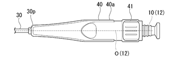
- FIG. 1 is a side view of the stent delivery system 100 according to the present embodiment.
- the stent delivery system 100 includes a guide wire G, a guide catheter 10, a stent 20, a pusher catheter 30, and an operation unit 40.
- the guide wire G guides the guide catheter 10, the stent 20, and the pusher catheter 30 to the narrowed portion.
- the guidewire G is introduced into the bile duct through the endoscopic channel.
- the tip of the guide wire G is inserted to a position beyond the narrowed portion.
- the guide catheter 10 assists the stent 20 to enter the narrowed portion.
- the guide catheter 10 has a catheter lumen 11 and an operating wire 12.
- the catheter lumen 11 is a tubular member made of resin or the like.
- a guide wire G is inserted through the catheter lumen 11. The guide catheter 10 is guided to the narrowed portion by the guide wire G.
- a stent 20 is installed on the outer circumference of the catheter lumen 11. With the stent 20 installed, the tip 11t of the catheter lumen 11 is exposed from the stent 20. In the guide catheter 10, the tip 11t of the catheter lumen 11 is inserted into the stenosis portion before the stent 20. The catheter lumen 11 widens the stenosis and assists the stent 20 in entering the stenosis.
- the operation wire 12 pushes and pulls the catheter lumen 11 to move it to the distal end side and the proximal end side.
- the operating wire 12 is connected to the proximal end 11p of the catheter lumen 11.
- the stent 20 is a tubular member made of resin or the like.
- the stent 20 is installed on the outer periphery of the catheter lumen 11 of the guide catheter 10.
- the stent 20 is joined and fixed to the catheter lumen 11.
- the pusher catheter 30 places the stent 20 in the stenosis.
- the pusher catheter 30 is a tubular member made of resin or the like.
- a guide wire G and a guide catheter 10 are inserted into the pusher catheter 30.
- the pusher catheter 30 is arranged closer to the proximal end of the guide catheter 10 than the stent 20.
- the inner diameter of the pusher catheter 30 is larger than the outer diameter of the catheter lumen 11 of the guide catheter 10.
- the inner and outer diameters of the pusher catheter 30 are substantially the same as the inner and outer diameters of the stent 20.
- the guide catheter 10 When the guide catheter 10 is pulled toward the proximal end side in a state where the guide catheter 10 and the stent 20 are released from fixation, the guide catheter 10 moves toward the proximal end side. Since the stent 20 is pressed by the pusher catheter 30, it does not move to the proximal end side. The stent 20 is detached from the guide catheter 10 and placed in place.
- a guide wire port 30a is formed on the outer peripheral surface of the pusher catheter 30 at a position between the tip end 30t and the base end 30p.
- the guide wire G is discharged from the guide wire port 30a.
- the operation unit 40 sandwiches the guide catheter 10 extending from the base end 30p of the pusher catheter 30.
- the operation unit 40 sandwiches the guide catheter 10 and adjusts the length L of the guide catheter 10 being discharged from the tip 30t of the pusher catheter 30.
- FIG. 2 is an enlarged view of the operation unit 40.
- the operation unit 40 pushes and pulls the pusher catheter 30 along the guide wire G.
- the operating unit 40 adjusts the position of the guide catheter 10 with respect to the pusher catheter 30.
- the operation unit 40 includes a housing 40a, a lever 41, and a collet chuck 50.
- the collet chuck 50 has a collet portion 51 and a chuck nut 52.
- the housing 40a is provided at the proximal end 30p of the pusher catheter 30.
- the housing 40a is formed in a substantially cylindrical shape.
- the hollow portion of the housing 40a communicates with the hollow portion of the pusher catheter 30.
- the housing 40a has a front end side hollow portion 40b, an internal space 40c, a notch portion 40d, and a base end side hollow portion 40e.
- the front end side hollow portion 40b, the internal space 40c, and the base end side hollow portion 40e communicate with each other.
- the tip side hollow portion 40b is formed along the central axis O of the housing 40a.
- the distal end side hollow portion 40b communicates with the hollow portion of the pusher catheter 30.
- the operation wire 12 of the guide catheter 10 extending from the base end 30p of the pusher catheter 30 is inserted into the distal end side hollow portion 40b.
- the internal space 40c is formed along the central axis O of the housing 40a.
- the internal space 40c is formed on the proximal end side of the distal end side hollow portion 40b and communicates with the distal end side hollow portion 40b.
- the internal space 40c is formed closer to the outer peripheral surface 40f of the housing 40a than the front end side hollow portion 40b.
- the operation wire 12 is inserted into the internal space 40c.
- the cutout portion 40d is formed on the outer peripheral surface 40f on the base end side of the internal space 40c, and communicates the internal space 40c with the space outside the housing 40a.
- the cutout portion 40d is formed over a range of approximately 90 degrees around the central axis O of the housing 40a.
- the base end side hollow portion 40e is formed along the central axis O of the housing 40a.
- the base end side hollow portion 40e is formed on the base end side of the internal space 40c of the housing 40a and communicates with the internal space 40c.
- the base end side hollow portion 40e communicates with the space outside the housing 40a.
- the operation wire 12 is inserted through the base end side hollow portion 40e.
- the lever 41 switches between the fixed state and the released state of the guide catheter 10 by the operation unit 40.
- the lever 41 is integrally formed with the chuck nut 52 of the collet chuck 50, and rotates the collet chuck 50 to sandwich and release the operation wire 12 to switch between the fixed state and the released state.
- the lever 41 is arranged in the internal space 40c of the housing 40a.
- the lever 41 projects from the notch 40d formed on the outer peripheral surface 40f of the housing 40a.
- the lever 41 is rotatably attached to the housing 40a around the central axis O of the housing 40a.
- the lever 41 can rotate about 90 degrees around the central axis O along the notch 40d.
- FIG. 3 is a diagram showing a state in which the operation unit 40 has released the guide catheter 10 (released state).
- FIG. 3 is the same state as shown in FIG.
- FIG. 4 is a diagram showing a state (fixed state) in which the operation unit 40 fixes the guide catheter 10.
- the lever 41 rotates around the central axis O of the housing 40a to switch between the released state and the fixed state of the guide catheter 10.
- the lever 41 rotates clockwise by approximately 90 degrees from the base end side toward the tip end side
- the lever 41 In the fixed state, when the lever 41 rotates counterclockwise by approximately 90 degrees from the base end side toward the tip end side, the lever 41 is in the released state.
- the collet portion 51 is fixed to the housing 40a, and the operation wire 12 is sandwiched between the collet portions 51 and fixed to the housing 40a.
- the chuck nut 52 of the collet chuck 50 is operated by the lever 41.
- the collet chuck 50 is arranged in the internal space 40c of the housing 40a.
- the collet chuck 50 is arranged on the tip side of the lever 41.
- the collet portion 51 of the collet chuck 50 and the chuck nut 52 are formed so as to be relatively movable back and forth.
- the collet portion 51 has a male screw portion (screw) 51a and a collet 51b.
- the male screw portion 51a is formed in a substantially cylindrical shape.
- the male screw portion 51a is arranged so that the central axis CO overlaps with the central axis O of the housing 40a.
- the male screw portion 51a is fixed so that its position does not change relative to the housing 40a.
- the male screw portion 51a has a hollow portion 51c and a male screw 51d.
- the hollow portion 51c is formed along the central axis CO.
- the male screw portion 51a is arranged so that the hollow portion 51c communicates with the tip-side hollow portion 40b of the housing 40a.
- the operation wire 12 of the guide catheter 10 is inserted into the hollow portion 51c.
- the male screw 51d is formed on the outer peripheral surface of the male screw portion 51a along the central axis CO.
- the collet 51b is formed in a protruding shape protruding from the end portion 51e on the proximal end side of the male screw portion 51a toward the proximal end side.
- four collets 51b are provided.
- the four collets 51b are arranged symmetrically with respect to the central axis CO along the outer circumference of the operation wire 12 of the guide catheter 10.
- the collet 51b has an inner surface 51f and an outer surface 51g.
- the inner side surface 51f faces the operation wire 12 of the guide catheter 10.
- the inner side surface 51f is along the central axis CO.
- the outer surface 51g is formed on the collet 51b on the opposite side to the inner surface 51f.
- the outer side surface 51g has an outer peripheral tapered surface 51h and a chuck guide surface 51i.
- the outer peripheral tapered surface 51h is formed on the tip end side, and is separated from the central axis CO toward the proximal end side.
- the chuck guide surface 51i is formed on the proximal end side of the outer peripheral tapered surface 51h, and is inclined toward the central axis CO side toward the proximal end side.
- the chuck nut 52 is formed in a substantially tubular shape.
- the chuck nut 52 is arranged so that the central axis NO overlaps with the central axis O of the housing 40a.
- the chuck nut 52 is rotatably supported around the central axis O.
- the operation wire 12 of the guide catheter 10 is inserted into the hollow portion of the chuck nut 52.
- the chuck nut 52 is formed integrally with the lever 41.
- the lever 41 projects from the base end side of the outer peripheral surface of the chuck nut 52.
- the chuck nut 52 has a female screw portion (screw) 52a, a tapered portion 52b, and a straight pipe portion 52c.
- the female screw portion 52a is formed on the tip end side of the chuck nut 52.
- a female screw 52e is formed on the inner peripheral surface of the female screw portion 52a. The female screw 52e is screwed with the male screw 51d of the collet portion 51.
- the tapered portion 52b is formed on the proximal end side of the female screw portion 52a.
- the tapered portion 52b has an inner peripheral tapered surface (inner peripheral surface) 52t on the inner peripheral surface on the proximal end side.
- the diameter of the inner peripheral tapered surface 52t is reduced so as to be closer to the central axis NO side toward the proximal end side.
- the inner peripheral tapered surface 52t is provided with a first region R1.
- the first region R1 is a region provided on the inner peripheral surface of the chuck nut 52, and is a region whose diameter is reduced so as to be closer to the central axis NO side toward the proximal end side.
- the straight pipe portion 52c is formed on the proximal end side of the tapered portion 52b.
- the straight pipe portion 52c is formed in a cylindrical shape.
- the diameter of the straight pipe portion inner peripheral surface (inner peripheral surface) 52d of the straight pipe portion 52c is substantially constant.
- the inner peripheral surface 52d of the straight pipe portion is continuous with the inner peripheral tapered surface 52t.
- the straight pipe portion 52c is provided with a boundary position P2 and a second region R3.
- the boundary position P2 is a position provided on the inner peripheral surface of the chuck nut 52, and is a position of a boundary between the first region R1 and the second region R3.
- the boundary position P2 is provided at the end portion 52f on the tip end side of the straight pipe portion inner peripheral surface 52d of the straight pipe portion 52c.
- the second region R3 is a region provided on the inner peripheral surface of the chuck nut 52, and is a region in which the degree of diameter reduction closer to the central axis NO side toward the proximal end side is gentler than that of the first region R1. Does not reduce the diameter.
- the second region R3 includes the boundary position P2.
- the second region R3 is provided on the inner peripheral surface 52d of the straight pipe portion 52c.
- the user sets the length L to an appropriate length by pushing and pulling the operation wire 12 in the released state shown in FIGS. 2 and 3.
- the collet portion 51 and the chuck nut 52 are not in contact with each other (non-contact state).
- FIG. 5 is a diagram showing a collet chuck 50 when the lever 41 is rotated around the central axis O from the released state.
- the collet 51b of the collet portion 51 and the inner peripheral surface of the chuck nut 52 come into contact with each other.
- the chuck guide surface 51i of the collet 51b and the inner peripheral tapered surface 52t of the chuck nut 52 come into contact with each other.
- the collet 51b comes into contact with the first region R1 of the chuck nut 52 (first contact state).
- the collet chuck 50 bends the tip 51p of the collet 51b toward the central axis O side of the housing 40a when the chuck nut 52 approaches the collet portion 51.
- the tip 51p of the inner side surface 51f of the collet 51b bends and approaches the central axis O side of the housing 40a.
- the chuck guide surface 51i slides with respect to the inner peripheral tapered surface 52t, and the tip 51p of the collet 51b moves toward the central axis O side of the housing 40a. Bend.
- the outer surface 51g of the collet 51b comes into contact with the end portion 52f on the tip end side of the straight pipe portion inner peripheral surface 52d of the straight pipe portion 52c of the chuck nut 52.
- the collet 51b comes into contact with the boundary position P2 of the chuck nut 52.
- the collet 51b When the collet 51b comes into contact with the boundary position P2, the collet 51b is tightened from the inner peripheral surface 52d of the straight tube portion separated from the central axis 10o of the guide catheter 10 by a predetermined distance, and the tip 51p and the central axis 10o of the inner surface 51f of the collet 51b are tightened.
- the distance to and is a predetermined distance.
- the outer peripheral tapered surface 51h of the collet 51b is substantially parallel to the central axis O of the housing 40a.
- the outer peripheral tapered surface 51h of the collet 51b is arranged on the central axis O side of the straight pipe portion inner peripheral surface 52d.
- the collet 51b sandwiches the operating wire 12 of the guide catheter 10 with a force of a predetermined magnitude.
- the diameter of the inner peripheral surface 52d of the straight pipe portion is substantially constant, and the diameter is not reduced. Therefore, in the second contact state, when the chuck nut 52 approaches the collet portion 51, the tip 51p of the inner surface 51f of the collet 51b does not bend toward the central axis 10o of the guide catheter 10 and maintains a distance. ..
- FIG. 6 is a diagram showing the operation of the collet chuck 50 in the second region.
- the outer peripheral tapered surface 51h of the collet 51b is substantially parallel to the central axis O of the housing 40a.
- the collet 51b sandwiches the operating wire 12 of the guide catheter 10 with a force of a predetermined magnitude.
- the chuck nut 52 is provided with a first region R1 and a second region R3. Even if the chuck nut 52 is brought close to the collet portion 51 in contact with the second region R3, the tip 51p of the inner surface 51f of the collet 51b maintains the distance from the central axis 10o of the guide catheter 10 and the operation wire 12 Hold in. In the second region R3, the collet 51b sandwiches the operation wire 12 with a force of a predetermined magnitude. Therefore, the stent delivery system 100 can easily hold the guide catheter 10 with an appropriate tightening force even if the relative positions of the collet 51b and the chuck nut 52 in the fixed state are displaced due to manufacturing variations or the like.
- the shape of the collet 51b is maintained so that the outer peripheral tapered surface 51h of the collet 51b is along the central axis O of the housing 40a.
- the shape of the collet 51b is maintained by the outer peripheral tapered surface 51h coming into contact with the inner peripheral surface 52d of the straight pipe portion 52c.
- the distance between the inner surface 51f of the collet 51b and the central axis 10o of the guide catheter 10 is maintained at a predetermined distance.
- the tip 51p of the inner surface 51f of the collet 51b sandwiches the operation wire 12 of the guide catheter 10 with a force of a predetermined magnitude. Therefore, the collet 51b sandwiches the guide catheter 10 with an appropriate tightening force in the second region R3 without forming a complicated shape.
- the collet 51b has a chuck guide surface 51i.
- the chuck guide surface 51i slides with respect to the inner peripheral tapered surface 52t of the chuck nut 52, and the tip 51p of the collet 51b Is easy to bend toward the central axis O side of the housing 40a. Therefore, the collet chuck 50 can easily hold the operation wire 12 of the guide catheter 10.
- the collet 51b and the chuck nut 52 can relatively advance and retreat by forming a screw in the collet portion 51 and the chuck nut 52 and screwing them together. Therefore, when the collet 51b approaches the chuck nut 52 while being in contact with the chuck nut 52, the user can easily approach the collet 51b with a light force.
- the collet portion 51 Since the collet portion 51 is fixed in a relative position invariant to the housing 40a extending from the pusher catheter 30, the collet portion 51 is fixed in a relative position invariant to the pusher catheter 30. Therefore, when the collet 51b sandwiches the operation wire 12 and the collet 51b and the chuck nut 52 are relatively close to each other in the second region R3, the collet 51b does not move the guide catheter 10 with respect to the pusher catheter 30.
- the housing 40a has a lever 41. Therefore, it is easy for the user to move the collet portion 51 and the chuck nut 52 back and forth relatively easily.
- the diameter of the inner peripheral surface of the straight pipe portion constituting the second region R3 does not have to be constant.
- the diameter of the inner peripheral surface of the straight pipe portion may be reduced more gently than the diameter of the inner peripheral tapered surface 52t of the chuck nut forming the first region R1. If the degree of reduction in the diameter of the inner peripheral surface of the straight pipe portion is gentler than the degree of reduction in the diameter of the inner peripheral tapered surface 52t, the tip 51p of the inner side surface 51f is the center when the chuck nut 52 approaches the collet portion 51. The amount of bending closer to the shaft 10o side is smaller in the second contact state than in the first contact state.
- the collet chuck does not have to have an inner peripheral tapered surface 52t.
- the chuck guide surface 51i may be configured to abut on the corner of the end portion 52f of the straight pipe portion 52c without abuting on the inner peripheral tapered surface 52t.
- the definition of the first region R1 may be expanded to a region in which the tip 51p is bent toward the central axis O when the collet 51b is in contact with the approaching collet 51b and the collet portion 51 and the chuck nut are relatively close to each other. ..
- the collet chuck does not have to have the straight pipe portion 52c.
- An appropriate curvature may be formed on the inner side surface 61f and the outer surface 61g of the collet portion 61, and the collet 61b may be brought close to the chuck nut 62 while being in contact with the inner peripheral tapered surface 52t of the chuck nut 62.
- the tip end 51p is on the central axis O side.
- the amount of bending may be smaller than that of the first region R1.
- the collet chuck may hold the guide catheter 10 with an appropriate tightening force.
- the amount at which the tip 51p bends toward the central axis O when the collet 51b abuts and the collet portion 51 and the chuck nut are relatively close to each other is smaller than the first region R1.
- the definition may be expanded.
- the number of collets is not limited to four.
- the collet may be one. There may be two or more.
- the lever may be configured to be in the released state when it is rotated counterclockwise from the base end side to the tip end side, and to be in the fixed state when it is rotated clockwise.
- the lever does not have to have a rotatable range of 90 degrees.
- the guide catheter does not have to have the operation wire 12. In that case, only the catheter lumen constitutes the guide catheter, and the operating unit 40 sandwiches the catheter lumen.
- a guide wire port is formed on the outer peripheral surface of the guide catheter, and the guide wire G is discharged from the guide wire port.
Abstract
The closeness of a collet (51b) and a guide catheter (10) is changed by advancing a chuck nut (52) with respect to the collet (51b) provided at the proximal end (30p) of a pusher catheter (30) and arranged along the outer circumference of the guide catheter (10).
Description
本発明は、ステントデリバリーシステムに関する。
The present invention relates to a stent delivery system.
従来、ステントデリバリーシステムが用いられている。ステントデリバリーシステムは、内視鏡チャンネルを通して胆管内の狭窄部等の所望の位置にステントを到達させ留置する。
Conventionally, a stent delivery system has been used. The stent delivery system delivers and places a stent at a desired location, such as a stenosis in the bile duct, through an endoscopic channel.
ステントデリバリーシステムは、ガイドカテーテルを挟持するチャック機構を操作部に備える。チャック機構は、ガイドカテーテルを挟持することにより、ステントの先端からガイドカテーテルが放出される寸法を決定する。ステントの長さは施術によって異なるため、ステントの長さに合わせてステントの先端からガイドカテーテルが放出される寸法が調節される。
The stent delivery system is equipped with a chuck mechanism for sandwiching the guide catheter in the operation unit. The chuck mechanism determines the dimension in which the guide catheter is ejected from the tip of the stent by sandwiching the guide catheter. Since the length of the stent varies depending on the procedure, the dimension in which the guide catheter is discharged from the tip of the stent is adjusted according to the length of the stent.
ところで、ガイドカテーテル又はガイドワイヤ等の管状又はワイヤ状の構造を挟持する機構が、様々に提案されている。特許文献1に記載の医療用ガイドワイヤは、螺合する前部外筒と後部外筒との内部に収容されたチャック部によりワイヤ本体が挟持固定される。前部外筒に対して後部外筒をねじ込み進ませることにより、チャック部材のテーパー外面に後部外筒の先端部内壁面が当接しつつ移動する。この時の後部外筒の押圧によりこのスリット形成部が軸芯中空部に向って押され収縮し、ワイヤ本体を周りから締め付けワイヤ本体が挾持固定される。
By the way, various mechanisms for sandwiching a tubular or wire-like structure such as a guide catheter or a guide wire have been proposed. In the medical guide wire described in Patent Document 1, the wire main body is sandwiched and fixed by a chuck portion housed inside the front outer cylinder and the rear outer cylinder to be screwed. By screwing the rear outer cylinder into the front outer cylinder, the inner wall surface of the tip portion of the rear outer cylinder moves while being in contact with the tapered outer surface of the chuck member. At this time, the slit forming portion is pushed toward the hollow portion of the shaft core by the pressing of the rear outer cylinder and contracts, and the wire body is tightened from the surroundings to hold and fix the wire body.
しかしながら、特許文献1に記載の医療用ガイドワイヤは、前部外筒に後部外筒をねじ込むほどスリット形成部が軸芯中空部に向って押され収縮する構造である。スリット形成部がワイヤ本体を締め付ける力は、前部外筒に対して後部外筒をねじ込み過ぎると過剰に大きくなり、ねじ込みが足りないと不足する。そのため、特許文献1に記載の医療用ガイドワイヤは、ワイヤ本体を適切な締め付け力で安定して挟持することが難しかった。
However, the medical guide wire described in Patent Document 1 has a structure in which the slit forming portion is pushed toward the hollow portion of the shaft core and contracts as the rear outer cylinder is screwed into the front outer cylinder. The force with which the slit forming portion tightens the wire body becomes excessive when the rear outer cylinder is screwed too much with respect to the front outer cylinder, and becomes insufficient when the screwing is insufficient. Therefore, it is difficult for the medical guide wire described in Patent Document 1 to stably hold the wire body with an appropriate tightening force.
上記事情を踏まえ、本発明は、ガイドカテーテルを適切な締め付け力で安定して挟持しやすいステントデリバリーシステムの提供を目的とする。
Based on the above circumstances, an object of the present invention is to provide a stent delivery system that can stably hold a guide catheter with an appropriate tightening force.
本発明の第一の態様に係るステントデリバリーシステムは、内視鏡のチャンネルに挿通可能であり、ガイドワイヤが挿通可能なガイドカテーテルと、管状に形成され、前記ガイドカテーテルが挿通可能なステントと、管状に形成され、ガイドワイヤが挿通可能であり、前記ガイドカテーテルが挿通可能であり、前記ステントよりも基端側に配置されるプッシャーカテーテルと、前記プッシャーカテーテルの基端に設けられ、前記プッシャーカテーテルの前記基端から延出する前記ガイドカテーテルが挿通され前記ガイドカテーテルを挟持可能であるコレットチャックと、を備え、前記コレットチャックは、前記ガイドカテーテルの外周に沿って配置されるコレットと、前記コレットと相対的に進退可能に設けられ前記ガイドカテーテルが挿通されるチャックナットと、を有し、前記チャックナットは、前記コレットチャックの中心軸に対向する内周面が、前記コレットと当接しながら前記コレットに接近するにつれて前記コレットを締め付けて前記コレットを前記ガイドカテーテルの中心軸に近づける第1の領域と、前記第1の領域よりも前記コレットの反対側にあり前記コレットと当接しながら前記コレットに接近するにつれて前記コレットを前記ガイドカテーテルの前記中心軸に近づける量が前記第1の領域より小さい第2の領域と、を有する。
The stent delivery system according to the first aspect of the present invention includes a guide catheter that can be inserted into a channel of an endoscope and can be inserted with a guide wire, and a stent that is formed in a tubular shape and can be inserted with the guide catheter. A pusher catheter formed in a tubular shape, capable of inserting a guide wire, capable of inserting the guide catheter, and arranged on the proximal end side of the stent, and a pusher catheter provided at the proximal end of the pusher catheter. A collet chuck through which the guide catheter extending from the proximal end of the guide catheter can be inserted and capable of sandwiching the guide catheter is provided, and the collet chuck includes a collet arranged along the outer periphery of the guide catheter and the collet. The chuck nut has a chuck nut that is provided so as to be relatively movable back and forth and into which the guide catheter is inserted. A first region that tightens the collet as it approaches the collet to bring the collet closer to the central axis of the guide catheter, and a collet that is on the opposite side of the first region and is in contact with the collet. It has a second region in which the amount of the collet closer to the central axis of the guide catheter as it approaches is smaller than the first region.
上記ステントデリバリーシステムによれば、ガイドカテーテルを適切な締め付け力で挟持しやすいステントデリバリーシステムを提供することができる。
According to the above-mentioned stent delivery system, it is possible to provide a stent delivery system that makes it easy to hold the guide catheter with an appropriate tightening force.
本発明の第一実施形態について、図1から図8を参照して説明する。以下では、ステントデリバリーシステムにおいて、狭窄部に挿入される側を先端側とし、使用者側を基端側として説明する。
The first embodiment of the present invention will be described with reference to FIGS. 1 to 8. Hereinafter, in the stent delivery system, the side inserted into the stenosis portion will be referred to as the distal end side, and the user side will be referred to as the proximal end side.
本実施形態に係るステントデリバリーシステム100は、内視鏡チャンネルを通して例えば胆管内の狭窄部等の所望の位置にステント20を到達させ留置するシステムである。
The stent delivery system 100 according to the present embodiment is a system in which the stent 20 reaches a desired position such as a stenosis in the bile duct and is placed through an endoscopic channel.
図1は、本実施形態に係るステントデリバリーシステム100の側面図である。図1に示すように、ステントデリバリーシステム100は、ガイドワイヤGと、ガイドカテーテル10と、ステント20と、プッシャーカテーテル30と、操作部40と、を備える。
FIG. 1 is a side view of the stent delivery system 100 according to the present embodiment. As shown in FIG. 1, the stent delivery system 100 includes a guide wire G, a guide catheter 10, a stent 20, a pusher catheter 30, and an operation unit 40.
ガイドワイヤGは、ガイドカテーテル10と、ステント20と、プッシャーカテーテル30と、を狭窄部までガイドする。ガイドワイヤGは、内視鏡のチャンネルを通じて胆管内に導入される。ガイドワイヤGの先端は、狭窄部を越える位置まで挿入される。
The guide wire G guides the guide catheter 10, the stent 20, and the pusher catheter 30 to the narrowed portion. The guidewire G is introduced into the bile duct through the endoscopic channel. The tip of the guide wire G is inserted to a position beyond the narrowed portion.
ガイドカテーテル10は、ステント20の狭窄部への進入を補助する。ガイドカテーテル10は、カテーテルルーメン11と、操作ワイヤ12と、を有する。カテーテルルーメン11は、樹脂等で形成される管状の部材である。カテーテルルーメン11には、ガイドワイヤGが挿通される。ガイドカテーテル10は、ガイドワイヤGにより狭窄部までガイドされる。
The guide catheter 10 assists the stent 20 to enter the narrowed portion. The guide catheter 10 has a catheter lumen 11 and an operating wire 12. The catheter lumen 11 is a tubular member made of resin or the like. A guide wire G is inserted through the catheter lumen 11. The guide catheter 10 is guided to the narrowed portion by the guide wire G.
カテーテルルーメン11の外周には、ステント20が設置される。ステント20が設置された状態において、カテーテルルーメン11の先端11tがステント20から露出する。ガイドカテーテル10は、カテーテルルーメン11の先端11tがステント20より先に狭窄部に挿入される。カテーテルルーメン11は、狭窄部を拡げて、ステント20の狭窄部への進入を補助する。
A stent 20 is installed on the outer circumference of the catheter lumen 11. With the stent 20 installed, the tip 11t of the catheter lumen 11 is exposed from the stent 20. In the guide catheter 10, the tip 11t of the catheter lumen 11 is inserted into the stenosis portion before the stent 20. The catheter lumen 11 widens the stenosis and assists the stent 20 in entering the stenosis.
操作ワイヤ12は、カテーテルルーメン11を押し引きして先端側及び基端側に移動させる。操作ワイヤ12は、カテーテルルーメン11の基端11pに接続される。
The operation wire 12 pushes and pulls the catheter lumen 11 to move it to the distal end side and the proximal end side. The operating wire 12 is connected to the proximal end 11p of the catheter lumen 11.
ステント20は、樹脂等で形成される管状の部材である。ステント20は、ガイドカテーテル10のカテーテルルーメン11の外周に設置される。ステント20は、カテーテルルーメン11に接合され固定される。
The stent 20 is a tubular member made of resin or the like. The stent 20 is installed on the outer periphery of the catheter lumen 11 of the guide catheter 10. The stent 20 is joined and fixed to the catheter lumen 11.
プッシャーカテーテル30は、ステント20を狭窄部に留置する。プッシャーカテーテル30は、樹脂等で形成される管状の部材である。プッシャーカテーテル30には、ガイドワイヤG及びガイドカテーテル10が挿通される。プッシャーカテーテル30は、ステント20よりもガイドカテーテル10の基端側に配置される。
The pusher catheter 30 places the stent 20 in the stenosis. The pusher catheter 30 is a tubular member made of resin or the like. A guide wire G and a guide catheter 10 are inserted into the pusher catheter 30. The pusher catheter 30 is arranged closer to the proximal end of the guide catheter 10 than the stent 20.
プッシャーカテーテル30の内径は、ガイドカテーテル10のカテーテルルーメン11の外径よりも大きい。プッシャーカテーテル30の内径及び外径は、ステント20の内径及び外径と略同等である。ガイドカテーテル10が基端側に引っ張られることにより、ガイドカテーテル10に固定されたステント20が基端側に引っ張られる。基端側に引っ張られたステント20は、プッシャーカテーテル30に当接する。ステント20とプッシャーカテーテル30とが当接した状態において、ガイドカテーテル10が基端側に一定の大きさ以上の力で引っ張られると、ステント20とガイドカテーテル10とに、互いを引き離す力が生じる。ステント20とガイドカテーテル10とに、互いを引き離す力が生じることで、ステント20とガイドカテーテル10とが分離され、ガイドカテーテル10とステント20との固定が解除される。
The inner diameter of the pusher catheter 30 is larger than the outer diameter of the catheter lumen 11 of the guide catheter 10. The inner and outer diameters of the pusher catheter 30 are substantially the same as the inner and outer diameters of the stent 20. By pulling the guide catheter 10 toward the proximal end side, the stent 20 fixed to the guide catheter 10 is pulled toward the proximal end side. The stent 20 pulled toward the proximal end abuts on the pusher catheter 30. When the guide catheter 10 is pulled toward the proximal end side with a force of a certain magnitude or more while the stent 20 and the pusher catheter 30 are in contact with each other, a force is generated between the stent 20 and the guide catheter 10 to separate them from each other. When a force is generated between the stent 20 and the guide catheter 10 to separate them from each other, the stent 20 and the guide catheter 10 are separated from each other, and the fixation between the guide catheter 10 and the stent 20 is released.
ガイドカテーテル10とステント20との固定が解除された状態においてガイドカテーテル10を基端側に引っ張ると、ガイドカテーテル10は基端側に移動する。ステント20は、プッシャーカテーテル30に押えられるため、基端側に移動しない。ステント20は、ガイドカテーテル10から離脱して、その場に留置される。
When the guide catheter 10 is pulled toward the proximal end side in a state where the guide catheter 10 and the stent 20 are released from fixation, the guide catheter 10 moves toward the proximal end side. Since the stent 20 is pressed by the pusher catheter 30, it does not move to the proximal end side. The stent 20 is detached from the guide catheter 10 and placed in place.
プッシャーカテーテル30の外周面には、先端30tと基端30pとの間の位置に、ガイドワイヤポート30aが形成される。ガイドワイヤポート30aからはガイドワイヤGが放出される。
A guide wire port 30a is formed on the outer peripheral surface of the pusher catheter 30 at a position between the tip end 30t and the base end 30p. The guide wire G is discharged from the guide wire port 30a.
操作部40は、プッシャーカテーテル30の基端30pから延出するガイドカテーテル10を挟持する。操作部40は、ガイドカテーテル10を挟持し、ガイドカテーテル10がプッシャーカテーテル30の先端30tから放出される長さLを調節する。
The operation unit 40 sandwiches the guide catheter 10 extending from the base end 30p of the pusher catheter 30. The operation unit 40 sandwiches the guide catheter 10 and adjusts the length L of the guide catheter 10 being discharged from the tip 30t of the pusher catheter 30.
図2は、操作部40の拡大図である。操作部40は、プッシャーカテーテル30をガイドワイヤGに沿って押し引きする。操作部40は、プッシャーカテーテル30に対するガイドカテーテル10の位置を調節する。図2に示すように、操作部40は、筐体40aと、レバー41と、コレットチャック50と、を有する。コレットチャック50は、コレット部51と、チャックナット52と、を有する。
FIG. 2 is an enlarged view of the operation unit 40. The operation unit 40 pushes and pulls the pusher catheter 30 along the guide wire G. The operating unit 40 adjusts the position of the guide catheter 10 with respect to the pusher catheter 30. As shown in FIG. 2, the operation unit 40 includes a housing 40a, a lever 41, and a collet chuck 50. The collet chuck 50 has a collet portion 51 and a chuck nut 52.
図2に示すように、筐体40aは、プッシャーカテーテル30の基端30pに設けられる。筐体40aは、略筒状に形成される。筐体40aは、中空部がプッシャーカテーテル30の中空部と連通する。筐体40aは、先端側中空部40bと、内部空間40cと、切り欠き部40dと、基端側中空部40eと、を有する。先端側中空部40bと、内部空間40cと、基端側中空部40eと、は連通する。
As shown in FIG. 2, the housing 40a is provided at the proximal end 30p of the pusher catheter 30. The housing 40a is formed in a substantially cylindrical shape. The hollow portion of the housing 40a communicates with the hollow portion of the pusher catheter 30. The housing 40a has a front end side hollow portion 40b, an internal space 40c, a notch portion 40d, and a base end side hollow portion 40e. The front end side hollow portion 40b, the internal space 40c, and the base end side hollow portion 40e communicate with each other.
先端側中空部40bは、筐体40aの中心軸Oに沿って形成される。先端側中空部40bは、プッシャーカテーテル30の中空部と連通する。先端側中空部40bには、プッシャーカテーテル30の基端30pから延出するガイドカテーテル10の操作ワイヤ12が挿通される。
The tip side hollow portion 40b is formed along the central axis O of the housing 40a. The distal end side hollow portion 40b communicates with the hollow portion of the pusher catheter 30. The operation wire 12 of the guide catheter 10 extending from the base end 30p of the pusher catheter 30 is inserted into the distal end side hollow portion 40b.
内部空間40cは、筐体40aの中心軸Oに沿って形成される。内部空間40cは、先端側中空部40bより基端側に形成され、先端側中空部40bに連通する。内部空間40cは、先端側中空部40bよりも筐体40aの外周面40fの近くまで形成される。内部空間40cには、操作ワイヤ12が挿通される。
The internal space 40c is formed along the central axis O of the housing 40a. The internal space 40c is formed on the proximal end side of the distal end side hollow portion 40b and communicates with the distal end side hollow portion 40b. The internal space 40c is formed closer to the outer peripheral surface 40f of the housing 40a than the front end side hollow portion 40b. The operation wire 12 is inserted into the internal space 40c.
切り欠き部40dは、内部空間40cの基端側の外周面40fに形成され、内部空間40cと筐体40aの外側の空間とを連通させる。切り欠き部40dは、筐体40aの中心軸O周りの略90度の範囲にわたって形成される。
The cutout portion 40d is formed on the outer peripheral surface 40f on the base end side of the internal space 40c, and communicates the internal space 40c with the space outside the housing 40a. The cutout portion 40d is formed over a range of approximately 90 degrees around the central axis O of the housing 40a.
基端側中空部40eは、筐体40aの中心軸Oに沿って形成される。基端側中空部40eは、筐体40aの内部空間40cより基端側に形成され、内部空間40cに連通する。基端側中空部40eは、筐体40aの外側の空間と連通する。基端側中空部40eには、操作ワイヤ12が挿通される。
The base end side hollow portion 40e is formed along the central axis O of the housing 40a. The base end side hollow portion 40e is formed on the base end side of the internal space 40c of the housing 40a and communicates with the internal space 40c. The base end side hollow portion 40e communicates with the space outside the housing 40a. The operation wire 12 is inserted through the base end side hollow portion 40e.
レバー41は、操作部40によるガイドカテーテル10の固定状態と、解放状態とを切替る。レバー41は、コレットチャック50のチャックナット52と一体的に形成され、コレットチャック50を回転させて操作ワイヤ12を挟持及び解放して、固定状態と解放状態とを切替る。
The lever 41 switches between the fixed state and the released state of the guide catheter 10 by the operation unit 40. The lever 41 is integrally formed with the chuck nut 52 of the collet chuck 50, and rotates the collet chuck 50 to sandwich and release the operation wire 12 to switch between the fixed state and the released state.
レバー41は、筐体40aの内部空間40cに配置される。レバー41は、筐体40aの外周面40fに形成される切り欠き部40dから突出する。レバー41は、筐体40aの中心軸O回りに回動可能に筐体40aに取り付けられる。レバー41は、中心軸O回りに、切り欠き部40dに沿って略90度回動可能である。
The lever 41 is arranged in the internal space 40c of the housing 40a. The lever 41 projects from the notch 40d formed on the outer peripheral surface 40f of the housing 40a. The lever 41 is rotatably attached to the housing 40a around the central axis O of the housing 40a. The lever 41 can rotate about 90 degrees around the central axis O along the notch 40d.
図3は、操作部40がガイドカテーテル10を解放した状態(解放状態)の図である。図3は、図2に示す状態と同一の状態である。図4は、操作部40がガイドカテーテル10を固定した状態(固定状態)の図である。図3及び図4に示すように、レバー41が筐体40aの中心軸O回りに回転することにより、ガイドカテーテル10の解放状態と固定状態とが切替えられる。解放状態において、レバー41が基端側から先端側に向かって右回りに略90度回転すると、固定状態となる。固定状態において、レバー41が基端側から先端側に向かって左回りに略90度回転すると、解放状態となる。
FIG. 3 is a diagram showing a state in which the operation unit 40 has released the guide catheter 10 (released state). FIG. 3 is the same state as shown in FIG. FIG. 4 is a diagram showing a state (fixed state) in which the operation unit 40 fixes the guide catheter 10. As shown in FIGS. 3 and 4, the lever 41 rotates around the central axis O of the housing 40a to switch between the released state and the fixed state of the guide catheter 10. In the released state, when the lever 41 rotates clockwise by approximately 90 degrees from the base end side toward the tip end side, the lever 41 is in the fixed state. In the fixed state, when the lever 41 rotates counterclockwise by approximately 90 degrees from the base end side toward the tip end side, the lever 41 is in the released state.
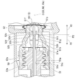
コレットチャック50は、コレット部51が筐体40aに対して固定され、操作ワイヤ12をコレット部51で挟持して筐体40aに対して固定する。コレットチャック50のチャックナット52は、レバー41により操作される。図2に示すように、コレットチャック50は、筐体40aの内部空間40cに配置される。コレットチャック50は、レバー41より先端側に配置される。コレットチャック50のコレット部51と、チャックナット52と、は相対的に進退可能に形成される。コレット部51は、雄螺子部(ねじ)51aと、コレット51bと、を有する。
In the collet chuck 50, the collet portion 51 is fixed to the housing 40a, and the operation wire 12 is sandwiched between the collet portions 51 and fixed to the housing 40a. The chuck nut 52 of the collet chuck 50 is operated by the lever 41. As shown in FIG. 2, the collet chuck 50 is arranged in the internal space 40c of the housing 40a. The collet chuck 50 is arranged on the tip side of the lever 41. The collet portion 51 of the collet chuck 50 and the chuck nut 52 are formed so as to be relatively movable back and forth. The collet portion 51 has a male screw portion (screw) 51a and a collet 51b.
雄螺子部51aは、略円筒状に形成される。雄螺子部51aは、中心軸COが筐体40aの中心軸Oと重なるように配置される。雄螺子部51aは、筐体40aに対して相対位置不変となるように固定される。雄螺子部51aは、中空部51cと、雄螺子51dと、を有する。中空部51cは、中心軸COに沿って形成される。雄螺子部51aは、中空部51cが筐体40aの先端側中空部40bと連通するように配置される。中空部51cには、ガイドカテーテル10の操作ワイヤ12が挿通される。雄螺子51dは、雄螺子部51aの外周面に中心軸COに沿って形成される。
The male screw portion 51a is formed in a substantially cylindrical shape. The male screw portion 51a is arranged so that the central axis CO overlaps with the central axis O of the housing 40a. The male screw portion 51a is fixed so that its position does not change relative to the housing 40a. The male screw portion 51a has a hollow portion 51c and a male screw 51d. The hollow portion 51c is formed along the central axis CO. The male screw portion 51a is arranged so that the hollow portion 51c communicates with the tip-side hollow portion 40b of the housing 40a. The operation wire 12 of the guide catheter 10 is inserted into the hollow portion 51c. The male screw 51d is formed on the outer peripheral surface of the male screw portion 51a along the central axis CO.
コレット51bは、雄螺子部51aの基端側の端部51eから基端側に突出する突起状に形成される。本実施形態では、コレット51bは4つ設けられる。4つのコレット51bは、ガイドカテーテル10の操作ワイヤ12の外周に沿って中心軸COに対して対称的に配置される。
The collet 51b is formed in a protruding shape protruding from the end portion 51e on the proximal end side of the male screw portion 51a toward the proximal end side. In this embodiment, four collets 51b are provided. The four collets 51b are arranged symmetrically with respect to the central axis CO along the outer circumference of the operation wire 12 of the guide catheter 10.
コレット51bは、内側面51fと、外側面51gと、を有する。内側面51fは、ガイドカテーテル10の操作ワイヤ12に対向する。内側面51fは、中心軸COに沿う。
The collet 51b has an inner surface 51f and an outer surface 51g. The inner side surface 51f faces the operation wire 12 of the guide catheter 10. The inner side surface 51f is along the central axis CO.
外側面51gは、コレット51bにおいて内側面51fと反対側に形成される。外側面51gは、外周テーパ面51hと、チャックガイド面51iと、を有する。外周テーパ面51hは、先端側に形成され、基端側ほど中心軸COから離間する。チャックガイド面51iは、外周テーパ面51hよりも基端側に形成され、基端側ほど中心軸CO側に傾斜する。
The outer surface 51g is formed on the collet 51b on the opposite side to the inner surface 51f. The outer side surface 51g has an outer peripheral tapered surface 51h and a chuck guide surface 51i. The outer peripheral tapered surface 51h is formed on the tip end side, and is separated from the central axis CO toward the proximal end side. The chuck guide surface 51i is formed on the proximal end side of the outer peripheral tapered surface 51h, and is inclined toward the central axis CO side toward the proximal end side.
チャックナット52は、略管状に形成される。チャックナット52は、中心軸NOが筐体40aの中心軸Oと重なるように配置される。チャックナット52は、中心軸O回りに回動可能に支持される。チャックナット52は、中空部にガイドカテーテル10の操作ワイヤ12が挿通される。チャックナット52は、レバー41と一体に形成される。レバー41は、チャックナット52の外周面の基端側から突出する。
The chuck nut 52 is formed in a substantially tubular shape. The chuck nut 52 is arranged so that the central axis NO overlaps with the central axis O of the housing 40a. The chuck nut 52 is rotatably supported around the central axis O. The operation wire 12 of the guide catheter 10 is inserted into the hollow portion of the chuck nut 52. The chuck nut 52 is formed integrally with the lever 41. The lever 41 projects from the base end side of the outer peripheral surface of the chuck nut 52.
チャックナット52は、雌螺子部(ねじ)52aと、テーパ部52bと、直管部52cと、を有する。雌螺子部52aは、チャックナット52の先端側に形成される。雌螺子部52aは、内周面に雌螺子52eが形成される。雌螺子52eは、コレット部51の雄螺子51dと螺合される。
The chuck nut 52 has a female screw portion (screw) 52a, a tapered portion 52b, and a straight pipe portion 52c. The female screw portion 52a is formed on the tip end side of the chuck nut 52. A female screw 52e is formed on the inner peripheral surface of the female screw portion 52a. The female screw 52e is screwed with the male screw 51d of the collet portion 51.
テーパ部52bは雌螺子部52aよりも基端側に形成される。テーパ部52bは、基端側の内周面に、内周テーパ面(内周面)52tを有する。内周テーパ面52tは、基端側ほど中心軸NO側に近づくように縮径する。図5に示すように、内周テーパ面52tは、第1の領域R1が設けられる。第1の領域R1は、チャックナット52の内周面に設けられる領域であり、基端側ほど中心軸NO側に近づくように縮径する領域である。
The tapered portion 52b is formed on the proximal end side of the female screw portion 52a. The tapered portion 52b has an inner peripheral tapered surface (inner peripheral surface) 52t on the inner peripheral surface on the proximal end side. The diameter of the inner peripheral tapered surface 52t is reduced so as to be closer to the central axis NO side toward the proximal end side. As shown in FIG. 5, the inner peripheral tapered surface 52t is provided with a first region R1. The first region R1 is a region provided on the inner peripheral surface of the chuck nut 52, and is a region whose diameter is reduced so as to be closer to the central axis NO side toward the proximal end side.
図2に示すように、直管部52cは、テーパ部52bよりも基端側に形成される。直管部52cは、円筒状に形成される。直管部52cの直管部内周面(内周面)52dは、径が略一定である。直管部内周面52dは、内周テーパ面52tと連続する。
As shown in FIG. 2, the straight pipe portion 52c is formed on the proximal end side of the tapered portion 52b. The straight pipe portion 52c is formed in a cylindrical shape. The diameter of the straight pipe portion inner peripheral surface (inner peripheral surface) 52d of the straight pipe portion 52c is substantially constant. The inner peripheral surface 52d of the straight pipe portion is continuous with the inner peripheral tapered surface 52t.
直管部52cには、図5及び図6に示すように、境界位置P2と、第2の領域R3と、が設けられる。境界位置P2は、チャックナット52の内周面に設けられる位置であり、第1の領域R1と第2の領域R3との境界の位置である。境界位置P2は、直管部52cの直管部内周面52dの先端側の端部52fに設けられる。
As shown in FIGS. 5 and 6, the straight pipe portion 52c is provided with a boundary position P2 and a second region R3. The boundary position P2 is a position provided on the inner peripheral surface of the chuck nut 52, and is a position of a boundary between the first region R1 and the second region R3. The boundary position P2 is provided at the end portion 52f on the tip end side of the straight pipe portion inner peripheral surface 52d of the straight pipe portion 52c.
第2の領域R3は、チャックナット52の内周面に設けられる領域であり、基端側ほど中心軸NO側に近づく縮径度合いが第1の領域R1より緩やかな領域であり、本実施形態では縮径しない。第2の領域R3は、境界位置P2を含む。第2の領域R3は、直管部52cの直管部内周面52dに設けられる。
The second region R3 is a region provided on the inner peripheral surface of the chuck nut 52, and is a region in which the degree of diameter reduction closer to the central axis NO side toward the proximal end side is gentler than that of the first region R1. Does not reduce the diameter. The second region R3 includes the boundary position P2. The second region R3 is provided on the inner peripheral surface 52d of the straight pipe portion 52c.
次に、図1に示すガイドカテーテル10がプッシャーカテーテル30の先端30tから放出される長さLを調節する動作について説明する。
Next, the operation of adjusting the length L of the guide catheter 10 shown in FIG. 1 discharged from the tip 30t of the pusher catheter 30 will be described.
まず、使用者は、図2及び図3に示す解放状態において、操作ワイヤ12を押し引きすることにより、長さLを適切な長さとする。解放状態においては、図2に示すように、コレット部51とチャックナット52とが接触していない(未接触状態)。
First, the user sets the length L to an appropriate length by pushing and pulling the operation wire 12 in the released state shown in FIGS. 2 and 3. In the released state, as shown in FIG. 2, the collet portion 51 and the chuck nut 52 are not in contact with each other (non-contact state).
使用者は、操作部40のレバー41を、解放状態から図4に示す固定状態に向けて、筐体40aの中心軸O回りに回転させる。図5は、レバー41を解放状態から中心軸O回りに回転させたときの、コレットチャック50を示す図である。
The user rotates the lever 41 of the operation unit 40 around the central axis O of the housing 40a from the released state to the fixed state shown in FIG. FIG. 5 is a diagram showing a collet chuck 50 when the lever 41 is rotated around the central axis O from the released state.
図5に示す通り、レバー41を中心軸O回りに回転させると、コレット部51の雄螺子51dに対してチャックナット52の雄螺子51dが回転し、コレット部51に対してチャックナット52が接近する。
As shown in FIG. 5, when the lever 41 is rotated around the central axis O, the male screw 51d of the chuck nut 52 rotates with respect to the male screw 51d of the collet portion 51, and the chuck nut 52 approaches the collet portion 51. do.
コレット部51に対してチャックナット52が接近すると、コレット部51のコレット51bと、チャックナット52の内周面が当接する。まず、コレット51bのチャックガイド面51iと、チャックナット52の内周テーパ面52tとが当接する。コレット51bが、チャックナット52の第1の領域R1内に当接する(第1当接状態)。
When the chuck nut 52 approaches the collet portion 51, the collet 51b of the collet portion 51 and the inner peripheral surface of the chuck nut 52 come into contact with each other. First, the chuck guide surface 51i of the collet 51b and the inner peripheral tapered surface 52t of the chuck nut 52 come into contact with each other. The collet 51b comes into contact with the first region R1 of the chuck nut 52 (first contact state).
レバー41を固定状態に近づけると、コレットチャック50は、コレット部51に対してチャックナット52が接近するとコレット51bの先端51pが筐体40aの中心軸O側に撓む。第1当接状態でコレット部51に対してチャックナット52が接近すると、コレット51bの内側面51fの先端51pが筐体40aの中心軸O側に撓み近づく。第1当接状態において、コレット部51に対してチャックナット52が接近すると、内周テーパ面52tに対してチャックガイド面51iがすべり、コレット51bの先端51pが筐体40aの中心軸O側に撓む。
When the lever 41 is brought closer to the fixed state, the collet chuck 50 bends the tip 51p of the collet 51b toward the central axis O side of the housing 40a when the chuck nut 52 approaches the collet portion 51. When the chuck nut 52 approaches the collet portion 51 in the first contact state, the tip 51p of the inner side surface 51f of the collet 51b bends and approaches the central axis O side of the housing 40a. When the chuck nut 52 approaches the collet portion 51 in the first contact state, the chuck guide surface 51i slides with respect to the inner peripheral tapered surface 52t, and the tip 51p of the collet 51b moves toward the central axis O side of the housing 40a. Bend.
コレット部51に対してチャックナット52を接近させると、やがてコレット51bの内側面51fの先端51p側が、ガイドカテーテル10の操作ワイヤ12に当接し、操作ワイヤ12を挟持する。
When the chuck nut 52 is brought close to the collet portion 51, the tip 51p side of the inner side surface 51f of the collet 51b eventually comes into contact with the operation wire 12 of the guide catheter 10 and sandwiches the operation wire 12.
さらにコレット部51に対してチャックナット52を接近させると、コレット51bの外側面51gが、チャックナット52の直管部52cの直管部内周面52dの先端側の端部52fに当接する。コレット51bは、チャックナット52の境界位置P2に当接する。
When the chuck nut 52 is further brought closer to the collet portion 51, the outer surface 51g of the collet 51b comes into contact with the end portion 52f on the tip end side of the straight pipe portion inner peripheral surface 52d of the straight pipe portion 52c of the chuck nut 52. The collet 51b comes into contact with the boundary position P2 of the chuck nut 52.
境界位置P2にコレット51bが当接すると、ガイドカテーテル10の中心軸10oと所定の距離離間する直管部内周面52dからコレット51bが締め付けられ、コレット51bの内側面51fの先端51pと中心軸10oとの距離が所定の距離となる。境界位置P2においては、コレット51bの外周テーパ面51hが、筐体40aの中心軸Oに略平行となる。境界位置P2においては、コレット51bの外周テーパ面51hが、直管部内周面52dより中心軸O側に配置される。境界位置P2においては、コレット51bは、所定の大きさの力でガイドカテーテル10の操作ワイヤ12を挟持する。
When the collet 51b comes into contact with the boundary position P2, the collet 51b is tightened from the inner peripheral surface 52d of the straight tube portion separated from the central axis 10o of the guide catheter 10 by a predetermined distance, and the tip 51p and the central axis 10o of the inner surface 51f of the collet 51b are tightened. The distance to and is a predetermined distance. At the boundary position P2, the outer peripheral tapered surface 51h of the collet 51b is substantially parallel to the central axis O of the housing 40a. At the boundary position P2, the outer peripheral tapered surface 51h of the collet 51b is arranged on the central axis O side of the straight pipe portion inner peripheral surface 52d. At the boundary position P2, the collet 51b sandwiches the operating wire 12 of the guide catheter 10 with a force of a predetermined magnitude.
さらにコレット部51に対してチャックナット52を接近させると、コレット51bは、チャックナット52の第2の領域R3に当接する(第2当接状態)。
When the chuck nut 52 is further brought closer to the collet portion 51, the collet 51b comes into contact with the second region R3 of the chuck nut 52 (second contact state).
本実施形態のステントデリバリーシステム100では、直管部内周面52dは径が略一定であり、縮径しない。そのため、第2当接状態においては、コレット部51に対してチャックナット52が接近した場合に、コレット51bの内側面51fの先端51pがガイドカテーテル10の中心軸10o側に撓まず距離を維持する。
In the stent delivery system 100 of the present embodiment, the diameter of the inner peripheral surface 52d of the straight pipe portion is substantially constant, and the diameter is not reduced. Therefore, in the second contact state, when the chuck nut 52 approaches the collet portion 51, the tip 51p of the inner surface 51f of the collet 51b does not bend toward the central axis 10o of the guide catheter 10 and maintains a distance. ..
図6は、第2の領域におけるコレットチャック50の動作を示す図である。図6に示すように、第2の領域においては、コレット51bの外周テーパ面51hが筐体40aの中心軸Oに略平行となる。第2の領域R3においては、コレット51bは、所定の大きさの力でガイドカテーテル10の操作ワイヤ12を挟持する。
FIG. 6 is a diagram showing the operation of the collet chuck 50 in the second region. As shown in FIG. 6, in the second region, the outer peripheral tapered surface 51h of the collet 51b is substantially parallel to the central axis O of the housing 40a. In the second region R3, the collet 51b sandwiches the operating wire 12 of the guide catheter 10 with a force of a predetermined magnitude.
第2の領域R3において、コレット部51に対してチャックナット52を接近させると、やがてレバー41が固定状態における位置に配置される。
In the second region R3, when the chuck nut 52 is brought close to the collet portion 51, the lever 41 is eventually arranged at the fixed position.
本実施形態に係るステントデリバリーシステム100によれば、チャックナット52に、第1の領域R1と、第2の領域R3と、が設けられる。第2の領域R3に当接したコレット部51に対してチャックナット52を接近させてもコレット51bの内側面51fの先端51pがガイドカテーテル10の中心軸10oとの距離を維持したまま操作ワイヤ12を挟持する。第2の領域R3においては、コレット51bが、操作ワイヤ12を所定の大きさの力で挟持する。そのため、ステントデリバリーシステム100は、固定状態におけるコレット51bとチャックナット52との相対位置に製造上のばらつき等によるずれが生じても、ガイドカテーテル10を適切な締め付け力で挟持しやすい。
According to the stent delivery system 100 according to the present embodiment, the chuck nut 52 is provided with a first region R1 and a second region R3. Even if the chuck nut 52 is brought close to the collet portion 51 in contact with the second region R3, the tip 51p of the inner surface 51f of the collet 51b maintains the distance from the central axis 10o of the guide catheter 10 and the operation wire 12 Hold in. In the second region R3, the collet 51b sandwiches the operation wire 12 with a force of a predetermined magnitude. Therefore, the stent delivery system 100 can easily hold the guide catheter 10 with an appropriate tightening force even if the relative positions of the collet 51b and the chuck nut 52 in the fixed state are displaced due to manufacturing variations or the like.
第2の領域R3において、コレット51bの外周テーパ面51hが筐体40aの中心軸Oに沿うようにコレット51bの形状が維持される。外周テーパ面51hが直管部52cの直管部内周面52dに当接することにより、コレット51bの形状が維持される。これにより、コレット51bの内側面51fとガイドカテーテル10の中心軸10oとの距離が所定の距離に維持される。コレット51bの内側面51fの先端51pが、ガイドカテーテル10の操作ワイヤ12を所定の大きさの力で挟持する。そのため、複雑な形状を形成することなく、第2の領域R3においてコレット51bがガイドカテーテル10を適切な締め付け力で挟持する。
In the second region R3, the shape of the collet 51b is maintained so that the outer peripheral tapered surface 51h of the collet 51b is along the central axis O of the housing 40a. The shape of the collet 51b is maintained by the outer peripheral tapered surface 51h coming into contact with the inner peripheral surface 52d of the straight pipe portion 52c. As a result, the distance between the inner surface 51f of the collet 51b and the central axis 10o of the guide catheter 10 is maintained at a predetermined distance. The tip 51p of the inner surface 51f of the collet 51b sandwiches the operation wire 12 of the guide catheter 10 with a force of a predetermined magnitude. Therefore, the collet 51b sandwiches the guide catheter 10 with an appropriate tightening force in the second region R3 without forming a complicated shape.
コレット51bはチャックガイド面51iを有する。これにより、第1の領域R1において、コレット部51に対してチャックナット52を接近させたときに、チャックナット52の内周テーパ面52tに対してチャックガイド面51iがすべり、コレット51bの先端51pが筐体40aの中心軸O側に撓みやすい。そのため、コレットチャック50は、ガイドカテーテル10の操作ワイヤ12を挟持しやすい。
The collet 51b has a chuck guide surface 51i. As a result, when the chuck nut 52 is brought closer to the collet portion 51 in the first region R1, the chuck guide surface 51i slides with respect to the inner peripheral tapered surface 52t of the chuck nut 52, and the tip 51p of the collet 51b Is easy to bend toward the central axis O side of the housing 40a. Therefore, the collet chuck 50 can easily hold the operation wire 12 of the guide catheter 10.
コレットチャック50は、コレット部51とチャックナット52とにねじが形成され螺合されることにより、コレット51bとチャックナット52とが相対的に進退可能である。そのため、コレット51bがチャックナット52に当接しながら、チャックナット52に対して接近するときに、使用者が軽い力でコレット51bを接近させやすい。
In the collet chuck 50, the collet 51b and the chuck nut 52 can relatively advance and retreat by forming a screw in the collet portion 51 and the chuck nut 52 and screwing them together. Therefore, when the collet 51b approaches the chuck nut 52 while being in contact with the chuck nut 52, the user can easily approach the collet 51b with a light force.
コレット部51がプッシャーカテーテル30から延在する筐体40aに対して相対位置不変に固定されるため、コレット部51がプッシャーカテーテル30に対して相対位置不変に固定される。そのため、第2の領域R3においてコレット51bが操作ワイヤ12を挟持しながらコレット51bとチャックナット52とが相対的に接近するときに、コレット51bがガイドカテーテル10をプッシャーカテーテル30に対して移動させない。
Since the collet portion 51 is fixed in a relative position invariant to the housing 40a extending from the pusher catheter 30, the collet portion 51 is fixed in a relative position invariant to the pusher catheter 30. Therefore, when the collet 51b sandwiches the operation wire 12 and the collet 51b and the chuck nut 52 are relatively close to each other in the second region R3, the collet 51b does not move the guide catheter 10 with respect to the pusher catheter 30.
筐体40aは、レバー41を有する。そのため、使用者がコレット部51とチャックナット52とを相対的に進退させやすい。
The housing 40a has a lever 41. Therefore, it is easy for the user to move the collet portion 51 and the chuck nut 52 back and forth relatively easily.
以上、本発明の各実施形態について図面を参照して詳述したが、具体的な構成はこの実施形態に限られるものではなく、本発明の要旨を逸脱しない領域の設計変更等も含まれる。また、上述の実施形態および以下で示す変形例において示した構成要素は適宜に組み合わせて構成することが可能である。
Although each embodiment of the present invention has been described in detail with reference to the drawings, the specific configuration is not limited to this embodiment, and includes design changes in areas that do not deviate from the gist of the present invention. Further, the components shown in the above-described embodiment and the modified examples shown below can be appropriately combined and configured.
例えば、第2の領域R3を構成する直管部内周面の径は一定でなくてもよい。直管部内周面の径は第1の領域R1を構成するチャックナットの内周テーパ面52tの縮径度合いより緩やかに縮径してもよい。直管部内周面の径の縮径度合いが内周テーパ面52tの縮径度合いより緩やかであれば、コレット部51に対してチャックナット52が接近した場合に、内側面51fの先端51pが中心軸10o側に撓み近づく量は、第1当接状態よりも第2当接状態の方が小さい。これにより、第2当接状態においてコレット部51に対してチャックナット52が接近した場合に、コレット51bがガイドカテーテル10を締め付ける力の増大が抑制される。そのため、固定状態におけるコレット51bとチャックナットとの相対位置に製造上のばらつき等によるずれが生じても、ガイドカテーテル10を適切な締め付け力で挟持しやすい。
For example, the diameter of the inner peripheral surface of the straight pipe portion constituting the second region R3 does not have to be constant. The diameter of the inner peripheral surface of the straight pipe portion may be reduced more gently than the diameter of the inner peripheral tapered surface 52t of the chuck nut forming the first region R1. If the degree of reduction in the diameter of the inner peripheral surface of the straight pipe portion is gentler than the degree of reduction in the diameter of the inner peripheral tapered surface 52t, the tip 51p of the inner side surface 51f is the center when the chuck nut 52 approaches the collet portion 51. The amount of bending closer to the shaft 10o side is smaller in the second contact state than in the first contact state. As a result, when the chuck nut 52 approaches the collet portion 51 in the second contact state, an increase in the force with which the collet 51b tightens the guide catheter 10 is suppressed. Therefore, even if the relative positions of the collet 51b and the chuck nut in the fixed state are displaced due to manufacturing variations or the like, the guide catheter 10 can be easily pinched with an appropriate tightening force.
図7に示すように、コレットチャックは、内周テーパ面52tを有さなくてもよい。チャックガイド面51iが内周テーパ面52tとの当接を経ずに直管部52cの端部52fの角に当接するように構成してもよい。管部52cの端部52fの角とコレット51bとが当接した状態においてコレット部51とチャックナットとを相対的に接近させたときにコレット51bの先端51pが筐体40aの中心軸O側に撓むようにしてもよい。第1の領域R1は、接近するコレット51bが当接し、コレット部51とチャックナットとを相対的に接近させたときに先端51pを中心軸O側に撓ませる領域に定義を拡大されてもよい。
As shown in FIG. 7, the collet chuck does not have to have an inner peripheral tapered surface 52t. The chuck guide surface 51i may be configured to abut on the corner of the end portion 52f of the straight pipe portion 52c without abuting on the inner peripheral tapered surface 52t. When the collet portion 51 and the chuck nut are relatively close to each other in a state where the corner of the end portion 52f of the pipe portion 52c and the collet 51b are in contact with each other, the tip 51p of the collet 51b is moved to the central axis O side of the housing 40a. It may be bent. The definition of the first region R1 may be expanded to a region in which the tip 51p is bent toward the central axis O when the collet 51b is in contact with the approaching collet 51b and the collet portion 51 and the chuck nut are relatively close to each other. ..
図8に示すように、コレットチャックは、直管部52cを有さなくてもよい。コレット部61の内側面61f及び外側面61gに適切な曲率を形成し、コレット61bをチャックナット62の内周テーパ面52tに当接させながらチャックナット62に対して接近させてもよい。これにより、第1の領域R1より基端側でコレット51bとチャックナット62とが当接した状態においてコレット部51とチャックナットとを相対的に接近させたときに、先端51pが中心軸O側に撓む量を第1の領域R1より小さくしてもよい。これにより、コレットチャックがガイドカテーテル10を適切な締め付け力で挟持してもよい。第2の領域R3は、コレット51bが当接し、コレット部51とチャックナットとを相対的に接近させたときに先端51pが中心軸O側に撓む量が第1の領域R1より小さい領域に定義を拡大されてもよい。
As shown in FIG. 8, the collet chuck does not have to have the straight pipe portion 52c. An appropriate curvature may be formed on the inner side surface 61f and the outer surface 61g of the collet portion 61, and the collet 61b may be brought close to the chuck nut 62 while being in contact with the inner peripheral tapered surface 52t of the chuck nut 62. As a result, when the collet portion 51 and the chuck nut are relatively close to each other in a state where the collet 51b and the chuck nut 62 are in contact with each other on the proximal end side of the first region R1, the tip end 51p is on the central axis O side. The amount of bending may be smaller than that of the first region R1. As a result, the collet chuck may hold the guide catheter 10 with an appropriate tightening force. In the second region R3, the amount at which the tip 51p bends toward the central axis O when the collet 51b abuts and the collet portion 51 and the chuck nut are relatively close to each other is smaller than the first region R1. The definition may be expanded.
コレットの数は4つに限らない。コレットは一体であってもよい。2つ以上あってもよい。
The number of collets is not limited to four. The collet may be one. There may be two or more.
レバーは、基端側から先端側に向かって左回りに回転すると解放状態となり、右回りに回転すると固定状態となるように構成されてもよい。レバーは、回動可能範囲が90度でなくてもよい。
The lever may be configured to be in the released state when it is rotated counterclockwise from the base end side to the tip end side, and to be in the fixed state when it is rotated clockwise. The lever does not have to have a rotatable range of 90 degrees.
ガイドカテーテルは、操作ワイヤ12を有さなくてもよい。その場合は、カテーテルルーメンのみがガイドカテーテルを構成し、操作部40はカテーテルルーメンを挟持する。ガイドカテーテルの外周面には、ガイドワイヤポートが形成され、ガイドワイヤポートからガイドワイヤGが放出される。
The guide catheter does not have to have the operation wire 12. In that case, only the catheter lumen constitutes the guide catheter, and the operating unit 40 sandwiches the catheter lumen. A guide wire port is formed on the outer peripheral surface of the guide catheter, and the guide wire G is discharged from the guide wire port.
10 ガイドカテーテル
10o 中心軸
20 ステント
30 プッシャーカテーテル
40 操作部
40a 筐体
41レバー
50 コレットチャック
51 コレット部
51a 雄螺子部(ねじ)
51b コレット
51f 内側面
51g 外側面
51h 外周テーパ面
51i チャックガイド面
52 チャックナット
52a 雌螺子部(ねじ)
52b テーパ部
52c 直管部
52d 直管部内周面(内周面)
52t 内周テーパ面(内周面)
61b コレット
61f 内側面
61g 外側面
62 チャックナット
100 ステントデリバリーシステム
G ガイドワイヤ
O 中心軸
P2 境界位置
R1 第1の領域
R3 第2の領域 10 Guide catheter 10oCentral axis 20 Stent 30 Pusher catheter 40 Operation part 40a Housing 41 Lever 50 Collet chuck 51 Collet part 51a Male screw part (screw)
51b Collet 51f Inner side surface 51g Outer side surface 51h Outer surface tapered surface 51i Chuck guide surface 52 Chuck nut 52a Female screw part (screw)
52bTapered part 52c Straight pipe part 52d Straight pipe part inner peripheral surface (inner peripheral surface)
52t inner peripheral tapered surface (inner peripheral surface)
61b Collet 61f Inner side surface 61g Outer side surface 62 Chuck nut 100 Stent delivery system G Guide wire O Central axis P2 Boundary position R1 First area R3 Second area
10o 中心軸
20 ステント
30 プッシャーカテーテル
40 操作部
40a 筐体
41レバー
50 コレットチャック
51 コレット部
51a 雄螺子部(ねじ)
51b コレット
51f 内側面
51g 外側面
51h 外周テーパ面
51i チャックガイド面
52 チャックナット
52a 雌螺子部(ねじ)
52b テーパ部
52c 直管部
52d 直管部内周面(内周面)
52t 内周テーパ面(内周面)
61b コレット
61f 内側面
61g 外側面
62 チャックナット
100 ステントデリバリーシステム
G ガイドワイヤ
O 中心軸
P2 境界位置
R1 第1の領域
R3 第2の領域 10 Guide catheter 10o
52b
52t inner peripheral tapered surface (inner peripheral surface)
Claims (9)
- 内視鏡のチャンネルに挿通可能であり、ガイドワイヤが挿通可能なガイドカテーテルと、
管状に形成され、前記ガイドカテーテルが挿通可能なステントと、
管状に形成され、ガイドワイヤが挿通可能であり、前記ガイドカテーテルが挿通可能であり、前記ステントよりも基端側に配置されるプッシャーカテーテルと、
前記プッシャーカテーテルの基端に設けられ、前記プッシャーカテーテルの前記基端から延出する前記ガイドカテーテルが挿通され前記ガイドカテーテルを挟持可能であるコレットチャックと、を備え、
前記コレットチャックは、前記ガイドカテーテルの外周に沿って配置されるコレットと、前記コレットと相対的に進退可能に設けられ前記ガイドカテーテルが挿通されるチャックナットと、を有し、
前記チャックナットは、前記コレットチャックの中心軸に対向する内周面が、前記コレットと当接しながら前記コレットに接近するにつれて前記コレットを締め付けて前記コレットを前記ガイドカテーテルの中心軸に近づける第1の領域と、前記第1の領域よりも前記コレットの反対側にあり前記コレットと当接しながら前記コレットに接近するにつれて前記コレットを前記ガイドカテーテルの前記中心軸に近づける量が前記第1の領域より小さい第2の領域と、を有する、
ステントデリバリーシステム。 A guide catheter that can be inserted into the endoscope channel and a guide wire can be inserted,
A stent that is formed in a tubular shape and through which the guide catheter can be inserted,
A pusher catheter formed in a tubular shape, capable of inserting a guide wire, capable of inserting the guide catheter, and arranged on the proximal end side of the stent.
A collet chuck provided at the proximal end of the pusher catheter through which the guide catheter extending from the proximal end of the pusher catheter is inserted and capable of sandwiching the guide catheter is provided.
The collet chuck has a collet arranged along the outer circumference of the guide catheter, and a chuck nut provided so as to be able to advance and retreat relative to the collet and into which the guide catheter is inserted.
The chuck nut is a first type that tightens the collet as the inner peripheral surface facing the central axis of the collet chuck approaches the collet while abutting against the collet to bring the collet closer to the central axis of the guide catheter. The amount of the collet closer to the central axis of the guide catheter as it approaches the collet while being in contact with the region and the collet on the opposite side of the first region is smaller than the first region. Has a second area,
Stent delivery system. - 前記第1の領域は、基端側に向かって縮径し、
前記第2の領域は、前記基端側に向かって縮径する度合いが前記第1の領域より緩やかである、
請求項1に記載のステントデリバリーシステム。 The first region is reduced in diameter toward the proximal end side.
The degree of diameter reduction of the second region toward the proximal end side is gentler than that of the first region.
The stent delivery system according to claim 1. - 前記コレットは、前記チャックナットと接触していない状態において、
前記ガイドカテーテルに対向する内側面が前記コレットチャックの前記中心軸に沿い、
前記内側面と反対側の外側面が、前記チャックナットに近いほど前記コレットチャックの前記中心軸から離間する外周テーパ面を有し、
前記チャックナットは、
略管状に形成され、
前記内周面が、前記第1の領域を有する内周テーパ面と、前記内周テーパ面と連続して前記基端側に形成され円筒状の直管部の内側に形成され前記第2の領域を有する直管部内周面と、を有し、
前記コレットチャックは、前記コレットと前記チャックナットとが接近するにつれて前記コレットの前記外側面と前記チャックナットの前記内周テーパ面の前記第1の領域とが当接し、前記コレットの前記外周テーパ面と前記チャックナットの前記直管部内周面の前記第2の領域とが当接する、
請求項2に記載のステントデリバリーシステム。 The collet is not in contact with the chuck nut.
The inner surface facing the guide catheter is along the central axis of the collet chuck.
The outer surface opposite to the inner surface has an outer peripheral tapered surface that is closer to the chuck nut and is separated from the central axis of the collet chuck.
The chuck nut is
Formed in a substantially tubular shape,
The inner peripheral surface is formed on the proximal end side in succession with the inner peripheral tapered surface having the first region and the inner peripheral tapered surface, and is formed inside a cylindrical straight pipe portion. With the inner peripheral surface of the straight pipe part having a region,
In the collet chuck, as the collet and the chuck nut approach each other, the outer surface of the collet and the first region of the inner peripheral tapered surface of the chuck nut come into contact with each other, and the outer peripheral tapered surface of the collet. And the second region of the inner peripheral surface of the straight pipe portion of the chuck nut come into contact with each other.
The stent delivery system according to claim 2. - 前記コレットは、前記外側面が、前記外周テーパ面と連続して前記チャックナット側に形成され前記チャックナットに近いほど前記コレットチャックの前記中心軸側に傾斜するチャックガイド面を有し、
前記コレットの前記チャックガイド面と前記チャックナットの前記内周テーパ面の前記第1の領域とが当接する、
請求項3に記載のステントデリバリーシステム。 The collet has a chuck guide surface whose outer surface is formed on the chuck nut side in succession with the outer peripheral tapered surface and is inclined toward the central axis side of the collet chuck as it is closer to the chuck nut.
The chuck guide surface of the collet and the first region of the inner peripheral tapered surface of the chuck nut come into contact with each other.
The stent delivery system according to claim 3. - 前記コレットチャックは、前記コレットと前記チャックナットとにねじが形成され、前記コレットと前記チャックナットとが相対的に回転することにより前記コレットと前記チャックナットとが相対的に前記進退する、
請求項1又は請求項4に記載のステントデリバリーシステム。 In the collet chuck, a screw is formed between the collet and the chuck nut, and the collet and the chuck nut rotate relative to each other so that the collet and the chuck nut move back and forth relatively.
The stent delivery system according to claim 1 or 4. - 前記コレットは、前記プッシャーカテーテルに対して相対位置不変に設けられる、
請求項1から請求項5のうちいずれか一項に記載のステントデリバリーシステム。 The collet is provided in an invariant position relative to the pusher catheter.
The stent delivery system according to any one of claims 1 to 5. - 前記チャックナットは、外周面から突出するレバーを有する、
請求項1から請求項6のうちいずれか一項に記載のステントデリバリーシステム。 The chuck nut has a lever protruding from the outer peripheral surface.
The stent delivery system according to any one of claims 1 to 6. - 前記チャックナットは、前記内周面の前記第2の領域が前記ガイドカテーテルの前記中心軸と平行である、
請求項2に記載のステントデリバリーシステム。 The chuck nut has the second region of the inner peripheral surface parallel to the central axis of the guide catheter.
The stent delivery system according to claim 2. - 前記ガイドカテーテルは、
前記ステントが設置されるカテーテルルーメンと、
前記カテーテルルーメンに接続される操作ワイヤと、を有し、
前記コレットチャックは、前記操作ワイヤを挟持する、
請求項1から請求項8のうちいずれか一項に記載のステントデリバリーシステム。 The guide catheter
The catheter lumen in which the stent is installed and
With an operating wire connected to the catheter lumen,
The collet chuck sandwiches the operation wire.
The stent delivery system according to any one of claims 1 to 8.
Priority Applications (4)
| Application Number | Priority Date | Filing Date | Title |
|---|---|---|---|
| PCT/JP2020/016971 WO2021210183A1 (en) | 2020-04-17 | 2020-04-17 | Stent delivery system |
| CN202080099702.3A CN115426984A (en) | 2020-04-17 | 2020-04-17 | Stent delivery system |
| JP2022515182A JP7385010B2 (en) | 2020-04-17 | 2020-04-17 | Stent delivery system |
| US18/046,361 US20230053606A1 (en) | 2020-04-17 | 2022-10-13 | Cartridge system |
Applications Claiming Priority (1)
| Application Number | Priority Date | Filing Date | Title |
|---|---|---|---|
| PCT/JP2020/016971 WO2021210183A1 (en) | 2020-04-17 | 2020-04-17 | Stent delivery system |
Related Child Applications (1)
| Application Number | Title | Priority Date | Filing Date |
|---|---|---|---|
| US18/046,361 Continuation US20230053606A1 (en) | 2020-04-17 | 2022-10-13 | Cartridge system |
Publications (1)
| Publication Number | Publication Date |
|---|---|
| WO2021210183A1 true WO2021210183A1 (en) | 2021-10-21 |
Family
ID=78084770
Family Applications (1)
| Application Number | Title | Priority Date | Filing Date |
|---|---|---|---|
| PCT/JP2020/016971 WO2021210183A1 (en) | 2020-04-17 | 2020-04-17 | Stent delivery system |
Country Status (4)
| Country | Link |
|---|---|
| US (1) | US20230053606A1 (en) |
| JP (1) | JP7385010B2 (en) |
| CN (1) | CN115426984A (en) |
| WO (1) | WO2021210183A1 (en) |
Families Citing this family (1)
| Publication number | Priority date | Publication date | Assignee | Title |
|---|---|---|---|---|
| USD994884S1 (en) * | 2020-03-04 | 2023-08-08 | Olympus Corporation | Handle of stent placement device |
Citations (4)
| Publication number | Priority date | Publication date | Assignee | Title |
|---|---|---|---|---|
| JPH02277464A (en) * | 1989-01-27 | 1990-11-14 | C R Bard Inc | Ballon dilation catheter and use thereof |
| JP2005131413A (en) * | 2003-10-31 | 2005-05-26 | Codman & Shurtleff Inc | Connector assembly |
| US20110125133A1 (en) * | 2007-09-21 | 2011-05-26 | Sabin Corporation | Catheter Components and Assembly |
| WO2017213139A1 (en) * | 2016-06-08 | 2017-12-14 | オリンパス株式会社 | Guide catheter |
Family Cites Families (1)
| Publication number | Priority date | Publication date | Assignee | Title |
|---|---|---|---|---|
| US7819844B2 (en) | 2007-10-17 | 2010-10-26 | Gardia Medical Ltd. | Guidewire stop |
-
2020
- 2020-04-17 CN CN202080099702.3A patent/CN115426984A/en active Pending
- 2020-04-17 WO PCT/JP2020/016971 patent/WO2021210183A1/en active Application Filing
- 2020-04-17 JP JP2022515182A patent/JP7385010B2/en active Active
-
2022
- 2022-10-13 US US18/046,361 patent/US20230053606A1/en active Pending
Patent Citations (4)
| Publication number | Priority date | Publication date | Assignee | Title |
|---|---|---|---|---|
| JPH02277464A (en) * | 1989-01-27 | 1990-11-14 | C R Bard Inc | Ballon dilation catheter and use thereof |
| JP2005131413A (en) * | 2003-10-31 | 2005-05-26 | Codman & Shurtleff Inc | Connector assembly |
| US20110125133A1 (en) * | 2007-09-21 | 2011-05-26 | Sabin Corporation | Catheter Components and Assembly |
| WO2017213139A1 (en) * | 2016-06-08 | 2017-12-14 | オリンパス株式会社 | Guide catheter |
Also Published As
| Publication number | Publication date |
|---|---|
| JPWO2021210183A1 (en) | 2021-10-21 |
| CN115426984A (en) | 2022-12-02 |
| JP7385010B2 (en) | 2023-11-21 |
| US20230053606A1 (en) | 2023-02-23 |
Similar Documents
| Publication | Publication Date | Title |
|---|---|---|
| JP4833848B2 (en) | Medical device delivery system | |
| US8894567B2 (en) | Medical tube | |
| WO2014185515A1 (en) | Endoscope treatment tool | |
| WO2012114786A1 (en) | Therapeutic tool for endoscopes | |
| WO2018211587A1 (en) | Tissue clamping tool deployment system | |
| WO2021210183A1 (en) | Stent delivery system | |
| US20170000318A1 (en) | Stent delivery system | |
| US20230172439A1 (en) | A braking mechanism for a rotary operating member of a medical device | |
| US11478613B2 (en) | Catheter | |
| EP1920740B1 (en) | Stent supply instrument | |
| JP2006314714A (en) | Lithomyl | |
| JP5436800B2 (en) | Medical instruments | |
| US11684751B2 (en) | Guidewire | |
| JP5942050B2 (en) | Endoscope | |
| CN116490113A (en) | Medical device with adjustable rigidity | |
| JP4589664B2 (en) | Endoscope treatment device raising device | |
| JP2018175291A (en) | Sheath set and endoscope system | |
| WO2018043719A1 (en) | Medical instrument | |
| WO2016042843A1 (en) | Endoscope | |
| JP2001017386A (en) | Instrument for medical treatment | |
| JP2017077348A (en) | Endoscope | |
| WO2024024047A1 (en) | Delivery device | |
| WO2022249464A1 (en) | Delivery device and endoscope system | |
| WO2022029833A1 (en) | Medical manipulator system | |
| US20170252025A1 (en) | Steering tool with controlled distal flexibility |
Legal Events
| Date | Code | Title | Description |
|---|---|---|---|
| 121 | Ep: the epo has been informed by wipo that ep was designated in this application |
Ref document number: 20930806 Country of ref document: EP Kind code of ref document: A1 |
|
| ENP | Entry into the national phase |
Ref document number: 2022515182 Country of ref document: JP Kind code of ref document: A |
|
| NENP | Non-entry into the national phase |
Ref country code: DE |
|
| 122 | Ep: pct application non-entry in european phase |
Ref document number: 20930806 Country of ref document: EP Kind code of ref document: A1 |