WO2021205830A1 - 薬品払出装置、表示制御装置、薬品払出プログラム - Google Patents
薬品払出装置、表示制御装置、薬品払出プログラム Download PDFInfo
- Publication number
- WO2021205830A1 WO2021205830A1 PCT/JP2021/010784 JP2021010784W WO2021205830A1 WO 2021205830 A1 WO2021205830 A1 WO 2021205830A1 JP 2021010784 W JP2021010784 W JP 2021010784W WO 2021205830 A1 WO2021205830 A1 WO 2021205830A1
- Authority
- WO
- WIPO (PCT)
- Prior art keywords
- tablet
- unit
- drug
- dispensing
- tablets
- Prior art date
Links
Images


Classifications
-
- A—HUMAN NECESSITIES
- A61—MEDICAL OR VETERINARY SCIENCE; HYGIENE
- A61J—CONTAINERS SPECIALLY ADAPTED FOR MEDICAL OR PHARMACEUTICAL PURPOSES; DEVICES OR METHODS SPECIALLY ADAPTED FOR BRINGING PHARMACEUTICAL PRODUCTS INTO PARTICULAR PHYSICAL OR ADMINISTERING FORMS; DEVICES FOR ADMINISTERING FOOD OR MEDICINES ORALLY; BABY COMFORTERS; DEVICES FOR RECEIVING SPITTLE
- A61J3/00—Devices or methods specially adapted for bringing pharmaceutical products into particular physical or administering forms
Definitions
- the present invention relates to a drug dispensing device capable of dispensing tablets from a tablet cassette.
- a drug dispensing device that can dispense the tablet from a storage unit that accommodates a plurality of tablets, and the tablet contained in the tablet cassette can be automatically dispensed based on prescription data.
- a storage unit that accommodates a plurality of tablets
- the tablet contained in the tablet cassette can be automatically dispensed based on prescription data.
- this type of drug dispensing device may include a hand-spreading unit capable of dispensing tablets to be charged into a plurality of cells in units of the cells.
- the tablets to be dispensed can be dispensed using either a tablet cassette or a hand-spreading unit.
- the smaller the tablet size the more difficult it becomes to put the tablets into each mass of the hand-spreading unit, and the work efficiency of the user decreases.
- An object of the present invention is to provide a drug dispensing device and a drug dispensing program that can utilize a tablet cassette and a hand-spreading unit in consideration of the work efficiency of the user.
- the drug dispensing device has a first tablet dispensing unit capable of dispensing the tablet from a storage unit accommodating a plurality of tablets, and a first tablet dispensing unit capable of dispensing tablets to be charged into a plurality of cells in units of the mass.
- 2 Allocation processing that can assign the drug information of the tablet to be dispensed to the first tablet payout section or the mounting section to which the first tablet payout section is mounted and the second tablet payout section.
- a unit and a drive processing unit that dispenses the tablet to be dispensed from the first tablet dispensing unit or the second tablet dispensing unit based on the allocation result by the allocation processing unit.
- the allocation processing unit assigns the drug information of the tablet having the smaller size of the tablet among the plurality of types of tablets to be dispensed to the first tablet dispensing unit or the mounting unit with priority.
- a first tablet dispensing unit capable of dispensing the tablet from a storage unit accommodating a plurality of tablets and a tablet charged into a plurality of cells can be dispensed in units of the mass.
- a mounting unit and a second tablet dispensing unit on which the first tablet dispensing unit or the first tablet dispensing unit is mounted and the drug information of the tablet to be dispensed are transmitted to a processor that controls a drug dispensing device including the two tablet dispensing unit.
- An allocation step that can be assigned to any of It is a drug withdrawal program for. Then, in the allocation step, the drug information of the tablet having the smaller size of the tablet among the plurality of types of tablets to be dispensed is preferentially assigned to the first tablet dispensing unit or the mounting unit.
- a drug dispensing device and a drug dispensing program that can utilize a tablet cassette and a hand-spreading unit in consideration of the work efficiency of the user.
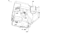
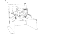
- FIG. 1 is an external view of a chemical dispensing device according to an embodiment of the present invention.
- FIG. 2 is a block diagram showing a system configuration of a chemical dispensing device according to an embodiment of the present invention.
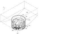
- FIG. 3 is a perspective view for explaining the configuration of a fixed tablet cassette of the drug dispensing device according to the embodiment of the present invention.
- FIG. 4 is a perspective view for explaining the configuration of a variable tablet cassette of the drug dispensing device according to the embodiment of the present invention.
- FIG. 5 is a perspective view for explaining the configuration of a variable tablet cassette of the drug dispensing device according to the embodiment of the present invention.
- FIG. 6 is a perspective view for explaining the configuration of a variable tablet cassette of the drug dispensing device according to the embodiment of the present invention.
- FIG. 1 is an external view of a chemical dispensing device according to an embodiment of the present invention.
- FIG. 2 is a block diagram showing a system configuration of a chemical dispensing device according to an embodiment of
- FIG. 7 is a perspective view for explaining a configuration of a mounting portion of a variable tablet cassette of the drug dispensing device according to the embodiment of the present invention.
- FIG. 8 is a diagram showing an example of the arrangement of masses of the hand-spreading unit in the chemical dispensing device according to the embodiment of the present invention.
- FIG. 9 is a diagram showing an example of a tablet packaging result in the drug dispensing device according to the embodiment of the present invention.
- FIG. 10 is a diagram showing an example of allocation information used in the drug dispensing device according to the embodiment of the present invention.
- FIG. 11 is a diagram showing an example of drive correspondence information used in the chemical dispensing device according to the embodiment of the present invention.
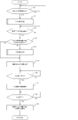
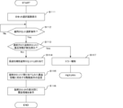
- FIG. 12 is a flowchart for explaining an example of the procedure of the drug dispensing process executed by the drug dispensing device according to the embodiment of the present invention.
- FIG. 13 is a flowchart for explaining an example of the procedure of the manual allocation process executed by the drug dispensing device according to the embodiment of the present invention.
- FIG. 14 is a flowchart for explaining an example of the procedure of the automatic allocation process executed by the drug dispensing device according to the embodiment of the present invention.
- FIG. 15 is a flowchart for explaining an example of the procedure of the packaging control process executed by the drug dispensing device according to the embodiment of the present invention.
- FIG. 16 is a diagram showing an example of a display screen displayed by the drug dispensing device according to the embodiment of the present invention.
- FIG. 17 is a diagram showing an example of a display screen displayed by the drug dispensing device according to the embodiment of the present invention.
- FIG. 18 is a diagram showing an example of a display screen displayed by the drug dispensing device according to the embodiment of the present invention.
- FIG. 19 is a diagram showing an example of allocation information used in the drug dispensing device according to the embodiment of the present invention.
- FIG. 20 is a diagram for explaining an example of a detection state of an optical sensor in the chemical dispensing device according to the embodiment of the present invention.
- FIG. 21 is a diagram for explaining an example of a detection state of an optical sensor in the chemical dispensing device according to the embodiment of the present invention.
- FIG. 22 is a flowchart for explaining another example of the procedure of the drug dispensing process executed by the drug dispensing device according to the embodiment of the present invention.
- FIG. 23 is a diagram showing an example of a display screen displayed by the drug dispensing device according to the embodiment of the present invention.
- FIG. 24 is a diagram showing an example of a display screen displayed by the drug dispensing device according to the embodiment of the present invention.
- FIG. 25 is a diagram showing an example of a display screen displayed by the drug dispensing device according to the embodiment of the present invention.
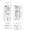
- the drug dispensing device 100 includes a prescription control unit 1, a tablet supply unit 2, a powder supply unit 3, a hand-spreading unit 4, a packaging unit 5, a packaging control unit 6, and a bar. It is equipped with a code reader 7 and the like.
- the prescription control unit 1, the tablet supply unit 2, the powder supply unit 3, the hand-spreading unit 4, the packaging unit 5, and the packaging control unit 6 are connected by an internal bus N1 or the like. Further, the prescription control unit 1 and the barcode reader 7 can perform wireless communication according to a communication standard such as wireless LAN or Bluetooth (registered trademark).
- the drug dispensing device 100 is controlled by the prescription control unit 1 and the packaging control unit 6, and based on the drug dispensing data, the tablet supply unit 2, the powder supply unit 3, and the hand-spreading unit 4 are used.
- the chemicals are dispensed from any one or more of the above, and the packaging unit 5 executes a packaging operation of packaging into packaging paper in units of packaging such as the time of administration.
- the packaging operation is once executed by the chemical dispensing device 100 based on the chemical dispensing data, and in the packaging operation, one type or a plurality of types of chemicals shown in the chemical dispensing data are used. Will be paid out.
- the drug withdrawal data is prescription data indicating the contents of a prescription corresponding to one patient
- the prescription data includes information about the patient and information about the drug such as the type, dose, and usage of the drug prescribed to the patient.
- the drug dispensing data is data corresponding to the one-time packaging operation in the drug dispensing device 10.
- the drug dispensing data may be dispensing data input to the drug dispensing device 100 based on the content of a prescription corresponding to one patient.
- the tablet supply unit 2 includes a plurality of fixed tablet cassettes 21 capable of paying out a predetermined specific type of tablet for each tablet (unit amount), and one tablet of any type (unit) by changing the driving conditions.
- a plurality of variable tablet cassettes 22 that can be dispensed for each amount) are provided.
- the tablets that can be dispensed by the fixed tablet cassette 21 and the variable tablet cassette 22 include various forms of solid chemicals such as disc-shaped, spherical, or capsule-shaped.
- the fixed tablet cassette 21 is provided in a total of 54 units of 6 vertical ⁇ 9 horizontal
- the variable tablet cassette 22 is provided below the fixed tablet cassette 22 in a total of 4 vertical ⁇ 4 horizontal.
- the tablet supply unit 2 may not have the fixed tablet cassette 21 but may have only a plurality of the variable tablet cassettes 22.
- Each of the fixed tablet cassettes 21 is detachably configured to be attached to and detachable from each of the mounting portions 211 provided in the tablet supply unit 2. As another embodiment, each of the fixed tablet cassettes 21 may be pulled out with respect to the mounting portion 211, and the fixed tablet cassette 21 may not be separated from the mounting portion 211. Further, a part of the fixed tablet cassette 21 may be provided on the mounting portion 211, and another part of the fixed tablet cassette 21 may be attached to and detached from the mounting portion 211.
- Each of the mounting portions 211 includes a first driving portion 23 that individually drives the fixed tablet cassette 21.
- Each of the first drive units 23 includes a drive motor 231 and an RFID reader / writer 232.
- the drive motor 231 supplies a driving force to the driving mechanism of the fixed tablet cassette 21.
- the RFID reader / writer 232 is an information reading means for reading / writing information from an RFID tag (not shown) provided on the fixed tablet cassette 21 by using the radio communication technology of RFID (Radio Frequency Identification).
- RFID Radio Frequency Identification
- the RFID tag (not shown) and the RFID reader / writer 232 are installed at the RFID tag (not shown) by the RFID reader / writer 232 with the fixed tablet cassette 21 mounted on the mounting portion 211. It suffices if the information is relatively defined within the range in which information can be read and written.
- the RFID tag (not shown) is a non-volatile recording medium in which cassette identification information or the like for identifying each of the fixed tablet cassettes 21 is stored, and the cassette identification information is an initial setting of the drug dispensing device 100 or the like. Is written by the prescription control unit 1. Further, the fixed tablet cassette 21 may be provided with a read-only RFID tag in which the cassette identification information corresponding to the fixed tablet cassette 21 is stored in advance.
- Each of the variable tablet cassettes 22 is detachably configured to be attached to and detachable from each of the mounting portions 221 provided in the tablet supply unit 2.
- the case where the variable tablet cassette 2 is an example of the first tablet dispensing unit according to the present invention will be described as an example.
- each of the variable tablet cassettes 22 may be retractable with respect to the mounting portion 221 so that the variable tablet cassette 22 does not separate from the mounting portion 221. Further, a part of the variable tablet cassette 22 may be provided on the mounting portion 221 and another portion of the variable tablet cassette 22 may be detachable from the mounting portion 221.
- Each of the mounting portions 221 includes a second driving portion 24 that individually drives the variable tablet cassette 22.
- Each of the second drive units 24 includes drive motors 241 to 244 and an RFID reader / writer 245. The drive motors 241 to 244 supply a driving force to the drive mechanism of the variable tablet cassette 22.
- the RFID reader / writer 245 (see FIG. 7) is an information reading means for reading / writing information from the RFID tag 26 (see FIG. 6) provided on the variable tablet cassette 22 by using RFID wireless communication technology. .. At the installation location of the RFID tag 26 and the RFID reader / writer 245, the RFID reader / writer 245 can read and write information on the RFID tag 26 with the variable tablet cassette 22 mounted on the mounting portion 221. It suffices if it is relatively defined within the range.
- the RFID tag 26 records cassette identification information for identifying each of the variable tablet cassettes 22, drug information of tablets assigned to the variable tablet cassette 22 in the drug dispensing process (see FIG. 12) described later, and the like. It is a non-volatile recording medium.
- the drug information is information that can identify the type of tablet (drug), such as a drug name, a drug ID, a JAN code, an RSS code, and a QR code (registered trademark).
- the JAN code and the RSS code are numerical values or character information represented by a one-dimensional code (bar code, GS1 code), and the QR code (registered trademark) is a numerical value or a numerical value indicated by a two-dimensional code. It is textual information.
- variable tablet cassettes 22 and the number of the mounting portions 221 may not match.
- the user can select an arbitrary variable tablet cassette 22 from the variable tablet cassettes 22 in a number larger than the number of the mounting portions 221 and mount the variable tablet cassette 22 on the mounting portion 221. This point is the same for the fixed tablet cassette 21 and the mounting portion 211.
- FIG. 3 is a diagram in which the cover member covering the upper portion of the fixed tablet cassette 21 is omitted.
- the type of tablet to be contained is predetermined. Therefore, for example, on the front surface of each of the fixed tablet cassettes 21, drug information of the tablets contained in the fixed tablet cassette 21 is described in advance.
- the fixed tablet cassette 21 includes a tablet storage unit 212 in which a plurality of tablets are stored, and a tablet discharge unit 213 in which tablets housed in the agent tablet storage unit 212 are individually discharged. There is.
- the tablet discharge unit 213 is provided in a recess formed in a substantially central portion of the tablet storage unit 212, and the tablets in the tablet storage unit 212 are sequentially lowered toward the tablet discharge unit 213.
- the tablet discharge unit 213 includes a rotor 214 rotatably supported by the housing of the fixed tablet cassette 21, and an inner wall 214A that covers the outer periphery of the rotor 214.
- the rotor 214 is connected to the drive motor 231 of the first drive unit 23 via a drive transmission system (not shown) such as various gears. Will be done.
- ribs 215 and 216 are formed on the outer peripheral surface of the rotor 214 at predetermined arrangement intervals.
- a gap 217 surrounded by the rib 215, the rib 216, and the inner wall 214A is intermittently formed on the outer periphery of the rotor 214.
- the width of the gap 217 is determined according to the type of tablet predetermined as a tablet to be accommodated in the fixed tablet cassette 21, and corresponds to the width of one tablet of the tablet.
- a gap 218 is formed between the ribs 215 and the ribs 216 over the entire outer peripheral surface of the rotor 214.
- the heights of the upper ends of the ribs 215 and the ribs 216 are determined according to the type of tablet predetermined as the tablet to be accommodated in the fixed tablet cassette 21. Specifically, the height of the upper end of the rib 215 shown in FIG. 3 corresponds to the height of three tablets, and three tablets are inserted into each of the gaps 217 of the rotor 214. Will be done. The height of the upper end of the rib 216 corresponds to the height of one tablet.
- the inner wall 214A is formed with a discharge port 219 for discharging tablets from the rotor 214, and the discharge port 219 is provided with a partition plate 220 to be inserted into the gap 218.
- the discharge port 219 of the three tablets inserted in the gap 217, the upper two tablets are restricted from falling by the partition plate 220, and only the lower one tablet is discharged. Therefore, in the fixed tablet cassette 21, the rotor 214 is driven by the drive motor 231 to pay out the tablets contained in the tablet accommodating portion 212 in units of one tablet.
- variable tablet cassette 22 Next, an example of the variable tablet cassette 22 will be described with reference to FIGS. 4 to 7.
- the structure of the variable tablet cassette 22 described here is only an example, and may have another structure as long as any tablet can be dispensed one by one.
- Japanese Patent Application Laid-Open No. 2010-535683 or Japanese Patent Application Laid-Open No. 2010-115493 discloses another example of the variable tablet cassette 22.
- the variable tablet cassette 22 is a cylindrical member having a spiral inner surface, and the tablets housed in the cylindrical member are spirally formed by rotating the cylindrical member in an inclined state. It may be configured to move to the upper part along the inner surface and be paid out in order.
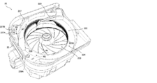
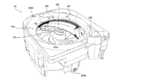
- variable tablet cassette 22 includes a tablet storage unit 222 in which a plurality of tablets are stored, and a first rotating body 223 and a second rotating body in which tablets are discharged from the tablet storage unit 222. It is equipped with 224. 4 to 6 are views in which the cover member covering the upper portion of the variable tablet cassette 22 is omitted. Further, the variable tablet cassette 22 may be configured as long as it is possible to dispense tablets in predetermined unit amounts, and may be configured such that tablets can be dispensed not in units of one tablet but in units of a plurality of tablets.
- the first rotating body 223 is a disk-shaped member constituting the bottom surface of the tablet accommodating portion 222.
- the rotation axis of the first rotating body 223 is inclined by a predetermined angle with respect to the vertical direction, and the upper surface of the first rotating body 223 is inclined by the predetermined angle with respect to the horizontal plane.
- radial ribs 223A are formed at predetermined intervals on the upper surface of the first rotating body 223.
- the first rotating body 223 is rotatably supported by the housing of the variable tablet cassette 22, and is connected to the drive gear 223B shown in FIGS. 5 and 6.
- the second rotating body 224 is a hollow annular member arranged around the first rotating body 223 in a plan view, and conveys the tablet of the tablet accommodating portion 222 to the payout outlet 225 to convey the tablet to the payout outlet 225. This is an example of a transport member to be paid out from. Further, the upper end portion of the first rotating body 223 is located on the same horizontal plane as the second rotating body 224.
- the second rotating body 224 is rotatably supported by the housing of the variable tablet cassette 22, and the drive gear 224A shown in FIG. 6 is formed on the outer peripheral surface.
- the mounting portion 221 has a drive gear 221A connected to the drive gear 223B of the first rotating body 223 when the variable tablet cassette 22 is mounted, and the second rotation.
- a drive gear 221B connected to the drive gear 224A of the body 224 is provided.
- the drive gear 221A is connected to the drive motor 241 of the second drive unit 24, and the drive gear 221B is connected to the drive motor 242 of the second drive unit 24.
- variable tablet cassette 22 has a height regulating member 226 and a height regulating member 226 arranged on the tablet payout path which is conveyed to the payout port 225 by the second rotating body 224.
- a width regulating member 227 is provided.
- the height regulating member 226 regulates the size of the tablet that can be conveyed to the payout port 225 by the second rotating body 224 in the height direction, and the width regulating member 227 is paid by the second rotating body 224. It regulates the widthwise size of tablets that can be transported to outlet 225.
- the height h1 regulated by the height regulating member 226 and the width w1 regulated by the width regulating member 227 among the tablets placed on the second rotating body 224 are obtained. Only the fitting tablets are dispensed from the payout outlet 225.
- the height h1 and the width w1 are equal to or larger than the height and width of one tablet accommodated in the tablet storage portion 222, and the height and width of at least two tablets. If it is smaller, the tablet can be dispensed in units of one tablet. More specifically, in the variable tablet cassette 22, when the center of gravity of the tablet is present on the second rotating body 224, the tablet may remain on the second rotating body 224, so that the width regulating member 227 It is conceivable that the width w1 regulated by the above is set to be equal to or greater than the width of 0.5 tablets of the tablet and smaller than the width of 1.5 tablets of the tablet.
- variable tablet cassette 22 changes the height adjusting portion 226A for changing the height h1 regulated by the height regulating member 226 and the width w1 regulated by the width regulating member 227. It is provided with a width adjusting unit 227A for the purpose. On the outer peripheral surface of the width adjusting portion 227A, a pinion gear meshed with a rack (gear) formed on the inner peripheral surface of the elongated hole 227B formed in the width regulating member 227 is formed.
- the height adjusting portion 226A is rotatably supported by the housing of the variable tablet cassette 22, and is connected to the drive gear 226B shown in FIG.
- the height adjusting unit 226A moves the position of the lower end portion of the height regulating member 226 up and down by being rotationally driven, and changes the height h1 regulated by the height regulating member 226.
- the width adjusting portion 227A is rotatably supported by the housing of the variable tablet cassette 22, and is connected to the drive gear 227C shown in FIG.
- the width adjusting portion 227A changes the amount of protrusion of the width regulating member 227 toward the tablet accommodating portion 222 by rotationally driving the drive gear 227C, and the width w1 regulated by the width regulating member 227.
- the amount of protrusion of the width regulating member 227 toward the tablet accommodating portion 222 is such that the width adjusting portion 227A and the elongated hole 227B each move in the arrow R3 direction (see FIG. 4) due to the rotation of the drive gear 227C. It is changed by moving relative to each other.
- the mounting portion 221 has a drive gear 221C connected to the drive gear 226B when the variable tablet cassette 22 is mounted, and a drive gear 221D connected to the drive gear 227C. It has.
- the drive gear 221C is connected to the drive motor 243 of the second drive unit 24, and the drive gear 221D is connected to the drive motor 244 of the second drive unit 24.
- the height regulating member 226 and the width regulating member 227 can be driven by the drive motors 243 and 244.
- variable tablet cassette 22 and the mounting portion 221 are connected to the drive gear 228A and the drive gear 228B when the variable tablet cassette 22 is mounted on the mounting portion 221. It has.
- the drive gear 228A is connected to an elevating mechanism (not shown) that elevates the first rotating body 223 in the vertical direction
- the drive gear 228B is connected to a drive motor (not shown).
- a driving force is transmitted from the drive gear 228B to the drive gear 228A, and the first rotating body 223 can be moved up and down by the elevating mechanism.
- the volume in the tablet accommodating portion 222 can be changed by raising and lowering the first rotating body 223, and the number of tablets accommodating in the tablet accommodating portion 222 can be changed. Can be adjusted arbitrarily. Therefore, the variable tablet cassette 22 can be used in both an application in which the number of tablets to be contained is small and an application in which the number of tablets to be contained is large.
- variable tablet cassette 22 when the first rotating body 223 is rotated in the rotation direction R1 (see FIGS. 4 and 5), the tablets of the tablet accommodating portion 222 are transferred from the first rotating body 223 to the first rotating body 223. It is discharged to the two-rotating body 224. Further, in the variable tablet cassette 22, when the second rotating body 224 is rotated in the rotation direction R2 (see FIGS. 4 and 5), the tablets on the second rotating body 224 are directed toward the payout outlet 225. Be transported.
- the tablets stacked in the height direction come into contact with the height regulating member 226 and are returned to the tablet accommodating portion 222.
- the tablets transported side by side in the width direction come into contact with the width regulating member 227 and are returned to the tablet accommodating portion 222.
- the tablet having a size corresponding to the height h1 regulated by the height regulating unit 226 and the width w1 regulated by the width regulating member 227 is the second rotating body.
- the tablets are transported to the payout port 225 in a state where the tablets are lined up one by one in the circumferential direction on the 224. Therefore, in the variable tablet cassette 22, the tablets stored in the tablet storage unit 222 can be dispensed in units of one tablet, and the amount of the tablets to be dispensed can be controlled.
- the height h1 regulated by the height regulating member 226 and the width w1 regulated by the width regulating member 227 can be changed, and thus any type can be used. It is possible to pay out the tablets of the above in units of one tablet.
- each of the variable tablet cassettes 22 is provided with a display unit 25 whose display contents can be changed.
- the display unit 25 is an electronic paper in which when the display content is written by energization, the display of the display content is maintained even in the non-energized state thereafter.
- each of the variable tablet cassette 22 and the mounting portion 221 is provided with a contact-type connector (not shown) to which the variable tablet cassette 22 is connected when the variable tablet cassette 22 is mounted on the mounting portion 221.
- the display unit 25 is connected to the connector on the variable tablet cassette 22 side
- the prescription control unit 1 is connected to the connector on the mounting unit 221 side.
- the display unit 25 and the prescription control unit 1 are electrically connected by the connector.
- the prescription control unit 1 can change the display of each of the display units 25.
- the display unit 25 is not limited to electronic paper, and may be another display means such as a liquid crystal display. It is also conceivable that the display unit 25 is provided on the mounting unit 221 on which the variable tablet cassette 22 is mounted corresponding to each of the variable tablet cassettes 22.
- each of the variable tablet cassettes 22 has a built-in RFID tag 26 for storing various information.
- the RFID tag 26 is a non-volatile recording medium in which the stored information can be rewritten by the RFID reader / writer 245.
- the cassette identification information of each of the variable tablet cassettes 22 and the variable tablet cassette 22 are each. It is used to store the drug information and the like assigned to.
- the RFID tag 26 is mounted on a control board provided on each of the variable tablet cassettes 22, and the control board is attached to the display unit 25 of the variable tablet cassette 22 according to a control signal from the prescription control unit 1. It also has a function to change the display.
- the control board is supplied with electric power supplied through the connector, electric power supplied from a power storage unit such as a battery mounted on the control board, or when information is written to the RFID tag 26. It is equipped with an electric circuit driven by electric power.
- a power storage unit such as a battery mounted on the control board
- each of the variable tablet cassettes 22 has another recording medium such as EEPROM in which the prescription control unit 1 can read and write information via the connector instead of the RFID tag 26. Considered as a form.
- the powder supply unit 3 includes two charging units 31 and 32, and powder charged into each of the charging units 31 and 32 is preset by the prescription control unit 1. It is supplied to the packaging unit 5 in units of packaging such as the time of administration.
- the powdered medicine supply unit 3 is an example of a powdered medicine dispensing unit according to the present invention.
- the powder supply unit 3 uniformly spreads the powder charged into the charging unit 31 on the disk and scrapes it out at predetermined angles corresponding to the packaging units, and the charging unit 32. It is provided with two sets of payout parts, which are a payout part in which the charged powder is evenly spread on a disk and scraped out at predetermined angles corresponding to the sachet units.
- the powder to be charged into the powder supply unit 3 is weighed in advance using a weighing device as the total amount of prescription drugs to be prescribed to the patient.
- the powder supply unit 3 there is a limit to the minimum angle at which the powder developed on the disk is scraped out by the dispensing unit, and the maximum angle that can be discharged from the powder unit 3 by charging the powder once into the powder unit 3 is limited. There is an upper limit to the number of packages. Further, the structure of the powder supply unit 3 is not limited to that described here, and any powder to be charged may be divided into a preset number of packages and dispensed.
- the hand-spreading unit 4 comprises a hand-spreading storage unit 41 in which a plurality of squares 411 into which tablets are charged in a preset unit of administration or the like are arranged side by side, and the tablets housed in each of the squares 411. Each of the squares 411 is provided with a hand-spraying unit for paying out to the packaging unit 5.
- the hand-spreading unit 4 is an example of a second tablet dispensing unit according to the present invention.
- the hand-spreading unit 4 is used for dispensing tablets such as tablets with a small number of tablets to be dispensed or half tablets with less than one tablet shown in the drug delivery data.
- a plurality of the squares 411 are arranged in a matrix in the vertical direction and the horizontal direction.
- the squares 411 may be arranged side by side in either the vertical direction or the horizontal direction, or may be arranged in a staggered manner.
- the hand-spraying unit can dispense the tablets contained in the mass 411 by individually opening and closing the bottom surface of the mass 411 of the hand-spreading accommodating unit 41, for example.
- the hand-spreading unit 4 can be used when paying out any tablet that is not stored in the fixed tablet cassette 21 in advance.
- tablets not contained in the fixed tablet cassette 21 can be dispensed using the variable tablet cassette 22 or the hand-spreading unit 4.
- each of the squares 411 is arranged adjacent to each other, and the size of each of the squares 411 is at least smaller than the tablet storage portion 222 of the variable tablet cassette 22. Therefore, when the size of the tablet is small, the work efficiency of the work of putting the tablet into each of the masses 411 is worse than the work of putting the tablet into the tablet accommodating portion 222. Further, in the hand-spreading unit 4, the maximum number of packages that can be dispensed from the hand-spreading unit 4 by putting a tablet into the hand-spreading unit 4 once is limited by the number of squares 411.
- the packaging unit 5 controls the drug dispensing device 100 based on the drug dispensing data, and one or a plurality of types supplied from the tablet supply unit 2, the powder supply unit 3, and the hand-spreading unit 4. Performs a packaging operation in which the drug is packaged in a single packaging paper in units of packaging such as when the drug is taken.
- the packaging unit 5 packages chemicals in the packaging units with a transparent or translucent roll-shaped chemical packaging sheet and seals the chemicals by welding or the like.
- the medicine package sheet containing the medicine in the package unit is discharged from the package unit 5.
- the packaging unit 5 can wrap the powder dispensed from the powder supply unit 3 and the tablets dispensed from the tablet supply unit 2 or the hand-spreading unit 4 with the same packaging paper. be.
- FIG. 9 is a diagram showing an example of the medicine packaging sheet 51 discharged from the packaging unit 5.
- a plurality of packaging papers 52 in which a plurality of tablets and powders are packaged are continuously formed in the packaging unit, and between the packaging papers 52. Is formed with a cut-out dotted line 52A (perforation) for easily separating each of the packaging papers 52.
- the packaging unit 5 only the tablets supplied from the tablet supply unit 2 or the hand-spreading unit 4 are packaged in the packaging paper 52, or the powder supplied from the powder supply unit 3. Only may be wrapped in the packing paper 52.
- the packaging unit 5 is provided with a printing unit (not shown) for printing information on each of the packaging papers 52, and the printing unit (not shown) is provided on the surface of each of the packaging papers 52.
- Can print prescription information such as the patient's name, time of administration, prescription drug, or prescription amount.
- the packaging control unit 6 includes a control unit 61 and a storage unit 62, and includes the tablet supply unit 2, the powder supply unit 3, the hand-spreading unit 4, the packaging unit 5, and the like. By controlling the above, the drug dispensing device 100 is made to execute the packaging operation.
- the packaging control unit 6 is built in the chemical dispensing device 100.
- the control unit 61 is a control means having a CPU, RAM, ROM, EEPROM, and the like.
- the control unit 61 executes various processes according to various programs stored in advance in a storage means such as the ROM, the EEPROM, or the storage unit 62 by the CPU.
- the RAM and EEPROM are used as temporary storage memories (working areas) for various processes executed by the CPU.
- the control unit 61 may be an integrated circuit such as an ASIC or DSP.
- the storage unit 62 is a storage means such as a hard disk device or SSD (Solid State Drive) that stores various types of data. Specifically, the storage unit 62 stores in advance a first drug dispensing program for causing a computer such as the control unit 61 to execute a packaging control process (FIG. 15) described later. Then, the control unit 61 functions as a drive processing unit according to the present invention by executing various processes according to the first drug dispensing program, and the fixed tablet cassette 21, the variable tablet cassette 22, and the powder supply unit. 3. It is possible to dispense chemicals from the hand-spreading unit 4 or the like and package them separately.
- SSD Solid State Drive
- the first chemical dispensing program is recorded on a computer-readable recording medium such as a CD, DVD, or semiconductor memory, and is read from the recording medium by a reading device such as a disk drive (not shown). It is installed in the storage unit 12.
- a computer-readable recording medium such as a CD, DVD, or semiconductor memory
- a reading device such as a disk drive (not shown). It is installed in the storage unit 12.
- the present invention can be regarded as an invention of the computer-readable recording medium on which the first drug dispensing program is recorded.
- the barcode reader 7 reads a code for identifying a drug, and is a JAN code or RSS code written on a tablet storage container (box, bottle, etc.) or a PTP sheet provided on a drug shelf of a pharmacy. , Or a code reader such as a PDA that can read code information such as a QR code (registered trademark).
- the barcode reader 7 may be, for example, a conventionally known picking assisting device used by a pharmacist or the like for picking a drug.
- the picking assist device is used when a pharmacist or the like takes out a medicine from a medicine shelf according to a prescription and manually dispenses the medicine. Check with the drug withdrawal data. Further, the barcode reader 7 may be used for reading a barcode or QR code written on a prescription.
- the information read by the barcode reader 7 is input from the barcode reader 7 to the prescription control unit 1 by wireless communication. It is also conceivable that the barcode reader 7 is connected to the prescription control unit 1 by wire.
- the bar code reader 7 associated with each of the drug dispensing devices 100 is individually provided.
- the prescription control unit 1 is a computer that comprehensively controls the drug dispensing device 100. As shown in FIGS. 1 and 2, the prescription control unit 1 includes a control unit 11, a storage unit 12, a monitor 13, an operation unit 14, a communication IF 15, and the like.
- the control unit 11 is a control means having a CPU, RAM, ROM, EEPROM, and the like.
- the control unit 11 is executed by the CPU in various processes according to various programs stored in advance in a storage means such as the ROM, the EEPROM, or the storage unit 12.
- the CPU is a processor that executes various processes, and the RAM and the EEPROM are used as a temporary storage memory (working area) for various processes executed by the CPU.
- the control unit 11 may be an integrated circuit such as an ASIC or DSP.
- the storage unit 12 is a storage means such as a hard disk device or SSD (Solid State Drive) that stores various types of data. Specifically, the storage unit 12 stores in advance a second chemical dispensing program for causing a computer such as the control unit 11 to execute a chemical dispensing process (see FIG. 12) described later.
- a second chemical dispensing program for causing a computer such as the control unit 11 to execute a chemical dispensing process (see FIG. 12) described later.
- control unit 11 includes a display processing unit 111, a reception processing unit 112, and an allocation processing unit 113.
- the control unit 11 functions as the display processing unit 111, the reception processing unit 112, and the allocation processing unit 113 by executing various processes according to the second chemical dispensing program.
- the display processing unit 111 has a plurality of selection areas for selecting each of the variable tablet cassettes 22 in the variable tablet cassette 22 in the drug dispensing device 100. It is possible to display the cassette selection screen D3 (see FIG. 18) displayed in the same arrangement as each arrangement. Further, the display processing unit 111 displays a prescription list screen D1 (see FIG. 16), a prescription input screen D2 (see FIG. 17), an input guide screen D4 (see FIGS. 23 and 24), which will be described later, on the monitor 13. indicate.
- the reception processing unit 112 can receive the selection operation of the selection area on the cassette selection screen D3. In addition, the reception processing unit 112 can also accept an input operation of drug information to be paid out.
- the allocation processing unit 113 can allocate drug information of the tablet to be paid out to the variable tablet cassette 22 corresponding to the selection area received by the reception processing unit 112. Further, the allocation processing unit 113 can automatically allocate the drug information of the tablet to be dispensed to either the variable tablet cassette 22 or the hand-spreading unit 4.
- the second chemical dispensing program is recorded on a computer-readable recording medium such as a CD, DVD, or semiconductor memory, and is read from the recording medium by a reading device such as a disk drive (not shown). It is installed in the storage unit 12.
- the present invention can be regarded as an invention of the computer-readable recording medium on which the second drug dispensing program is recorded.
- the first chemical dispensing program and the second chemical dispensing program are examples of a chemical dispensing program for causing the chemical dispensing device 100 to execute various processes.
- the drug dispensing device 100 does not have the packaging control unit 6, and the prescription control unit 1 also functions as the packaging control unit 6.
- the storage unit 12 stores a drug dispensing program in which the first drug dispensing program and the second drug dispensing program are integrated, and the control unit 11 describes later according to the drug dispensing program. It is conceivable to execute the chemical dispensing process and the packaging control process.
- the present invention can also be regarded as an invention of the computer-readable recording medium on which the drug dispensing program is recorded.
- various databases such as a drug master, a patient master, a cassette master, and a pharmacy master are also stored in the storage unit 12.
- the control unit 11 is stored in the storage unit 12 based on data read from a recording medium such as a CD, DVD, or semiconductor memory by a reading device such as a disk drive (not shown). It is possible to update the database of. Further, the control unit 11 can change the contents of the various databases according to a user operation on the operation unit 14.
- the drug master includes drug ID, drug name, JAN code (or RSS code), drug bottle code, classification (dosage form: powder, tablet, liquid medicine, external medicine, etc.), tablet size (height and width, etc.). ), Specific gravity, drug type (ordinary drug, poisonous drug, narcotic, powerful drug, antipsychotic drug, therapeutic drug, etc.), formulation change, excipient, precautions, etc. Information on each drug is included.
- the patient master includes information about the patient such as patient ID, name, gender, age, medical history, prescription drug history, family information, department, ward, and room.
- the pharmacy master includes information about the pharmacy, such as the name of the pharmacy, the name of the pharmacist, and the ID of the pharmacist.
- the cassette master is information indicating a correspondence relationship between the cassette identification information of each of the fixed tablet cassettes 21 mounted on the mounting portion 211 and the drug information assigned to each of the fixed tablet cassettes 21.
- the cassette master is registered by the control unit 11 in response to a user operation of the operation unit 14 in the initial setting of the chemical dispensing device 100, for example.
- the storage unit 12 contains the allocation information 121 indicating the allocation state between the variable tablet cassette 22 and the drug information, and the drive correspondence information indicating the correspondence relationship between the drug information and the drive condition of the variable tablet cassette 22. 122 is stored.
- the allocation information 121 and the drive correspondence information 122 are described later in a chemical dispensing process executed by the control unit 11. (See FIG. 12).
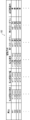
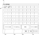
- FIG. 10 is a diagram showing an example of the allocation information 121
- FIG. 11 is a diagram showing an example of the drive correspondence information 122.
- a drug ID that can identify the type of tablet currently assigned to each of the variable tablet cassettes 22 is stored as drug information.
- drug information such as a drug name or JAN code (or RSS code) may be stored.
- cassette numbers "C1" to "C4" are preset as the cassette identification information in the four variable tablet cassettes 22 arranged in order from left to right in the tablet supply unit 2. And. The cassette identification information is also stored in the RFID tag 26 of each of the variable tablet cassettes 22.
- the allocation information 121 it is registered that the variable tablet cassette 22 to which the drug information is not currently assigned is in an unallocated state.
- the cassette number “C1” is the drug information of the drug ID “M1”
- the cassette number “C3” is the drug ID “M2”.
- the drug information is assigned, and the cassette numbers "C2" and "C4" indicate that the drug information has not yet been assigned and is in an unassigned state.
- the data structure of the allocation information 121 shown in FIG. 10 is merely an example, and the allocation information 121 may be stored in the storage unit 12 as, for example, one item of the drug master. In this case, the drug master stores the cassette identification information of the variable tablet cassette 22 assigned to the drug in association with each drug.
- the driving conditions include a pre-driving condition relating to the adjustment of the variable tablet cassette 22 before starting the dispensing of the tablet from the variable tablet cassette 22, and a driving control relating to the driving control during the dispensing of the tablet from the variable tablet cassette 22.
- a condition and a drive stop condition relating to drive control when stopping the dispensing of tablets from the variable tablet cassette 22.
- the payout route is set as the drive condition corresponding to each tablet whose drug IDs are “M1”, “M2”, “M3”, and “M4”.
- Information on each item of height, payout path width, payout speed, first slowdown, second slowdown, and reverse rotation operation is stored.
- the driving condition is only an example.
- the vibration frequency or amplitude of the vibration is defined as the driving condition. It is possible that there is.
- the height of the payout path and the width of the payout path are examples of the pre-driving conditions, and tablets are dispensed one by one from the payout outlet 225 by the second rotating body 224 of the variable tablet cassette 22. These are the values of the height h1 and the width w1 (see FIG. 5) that are preset as possible values.
- the dispensing speed is an example of the driving condition, and is a rotation speed suitable for each drug information as the rotation speed of the second rotating body 224 when the tablets are discharged from the variable tablet cassette 22.
- the tablet dispensing speed set as the driving condition that is, the tablet transport speed by the second rotating body 224, differs depending on the tablet size.
- the payout speed when the tablet size is large is set to a value faster than the payout speed when the tablet size is small.
- the payout speed is not limited to the format of [lock / min] shown in FIG. 11, and may be stored in a format such as the rotation speed of the second rotating body 224 or the rotation speed of the drive motor 242. .. Further, it is conceivable that not only the rotation speed of the second rotating body 224 but also the rotation speed of the first rotating body 223 is set as the driving condition.
- the first slowdown and the second slowdown are examples of the drive stop condition, and the rotation speed of the second rotating body 224 is gradually increased when the dispensing of tablets from the variable tablet cassette 22 is stopped.
- the first slowdown defines a timing for decelerating the rotation speed of the second rotating body 224 to a predetermined first rotation speed.
- the second slowdown defines a timing for decelerating the rotation speed of the second rotating body 224 from the first rotation speed to a slower second rotation speed. For example, if the shape of the tablet contained in the variable tablet cassette 22 is rounded and easily rolls, the tablet may roll and be discharged after stopping the driving of the second rotating body 224.
- the start timings of the first slowdown and the second slowdown are set earlier.
- the start timing of the first slowdown and the second slowdown is set by the remaining number of tablets to be dispensed from the variable tablet cassette 22. This prevents the extra tablets from being dispensed when the dispensing of the tablets from the variable tablet cassette 22 is stopped.
- the start timings of the first slowdown and the second slowdown are set late, so that the slowdown is unnecessary. Delays in payout time due to the above are suppressed.
- the case where the start timings of the first slowdown and the second slowdown are set as the drive stop condition will be described, but the deceleration of the rotation speed of the second rotating body 224 will be described. May be set as the drive stop condition.
- a tablet having a shape that is easy to roll such as a sphere
- the second rotating body 224 if the second rotating body 224 is suddenly stopped, it may roll and be discharged extra. Therefore, for example, for a tablet having a shape that is easy to roll, it is conceivable to set the deceleration to a small value.
- the item of the reverse rotation operation is an example of the drive stop condition, and when the dispensing of the tablet from the variable tablet cassette 22 is stopped, the tablet transport direction by the second rotating body 224 is reversed. Information on whether or not the reverse rotation operation is executed. For example, if the driving of the second rotating body 224 is simply stopped, the tablets remaining on the second rotating body 224 may roll and be discharged excessively. The operation is set to "Yes". This prevents the extra tablets from being dispensed when the dispensing of the tablets from the variable tablet cassette 22 is stopped. For tablets having a shape that is difficult to roll when the driving of the second rotating body 224 is stopped, the reverse rotation operation is set to "None", and the unnecessary reverse rotation operation is not executed.
- the data structure of the drive correspondence information 122 shown in FIG. 11 is merely an example, and the drive condition defined in the drive correspondence information 122 is stored in the storage unit 12 as, for example, one item of the drug master. It may be the one that has been done.
- the chemical dispensing device 100 sets any one or more of the height of the dispensing path, the width of the dispensing path, the dispensing speed, the first slowdown, the second slowdown, and the reverse rotation operation as the driving conditions. Can also be considered as another embodiment.
- any one or a plurality of the pre-driving condition, the driving condition, and the driving stop condition are preset as the driving conditions corresponding to the chemical information. Can be considered. Further, a plurality of conditions such as the pre-driving condition, the driving condition, and the driving stop condition are set in advance as the driving conditions corresponding to the chemical information, and are used in the chemical dispensing device 100.
- the driving condition to be performed one or a plurality of conditions such as the pre-driving condition, the driving condition, and the driving stop condition can be selected.
- the monitor 13 is a display means such as a liquid crystal display that displays various information and operation screens according to a control instruction from the control unit 11. For example, the monitor 13 displays various information such as a drug payout data input screen, a drug payout data selection screen, and a variable tablet cassette 22 selection screen.
- the operation unit 14 is an operation means such as a keyboard, a mouse, and a touch panel that accepts user operations, and inputs an operation signal corresponding to the user operation to the control unit 11.
- the operation unit 14 is, for example, an operation of inputting drug withdrawal data on the input screen displayed on the monitor 13, an operation of selecting drug withdrawal data on the selection screen, an operation of selecting a variable tablet cassette 22 on the selection screen, and the operation of the variable tablet cassette 22.
- It is a touch panel that accepts various operation inputs such as issuing operation of drug withdrawal data requesting the start of packaging of drug withdrawal data.
- the communication IF 15 is a communication interface for connecting the drug dispensing device 100 to a communication network N3 such as a LAN, and is connected to a higher-level system such as a prescription input terminal 200 connected via the communication network N3. Perform data communication.
- the prescription input terminal 200 is, for example, an electronic medical record system arranged in a hospital or a health facility for the elderly, a dispensing management system arranged in an in-hospital or out-of-hospital pharmacy, or the like.
- the communication IF 15 also includes a wireless communication interface such as a wireless communication card that performs wireless data communication with various wireless communication devices such as the barcode reader 7.
- the communication IF 15 acquires the drug payout data from the prescription input terminal 200, and inputs the drug payout data to the control unit 11. For example, the communication IF 15 monitors whether or not drug delivery data is stored in a predetermined storage area of a storage means provided in the prescription input terminal 200, and the drug delivery data is stored in the predetermined storage area. When stored, the drug payout data is read out from the predetermined storage area. Of course, the communication IF 15 may receive the drug payout data transmitted from the prescription input terminal 200.
- step S1 the control unit 11 determines whether or not a cassette selection start operation for manually assigning the drug information to the variable tablet cassette 22 has been performed for the arbitrary drug withdrawal data. For example, when arbitrary drug withdrawal data is selected and an operation of selecting a drug to be assigned to the variable tablet cassette 22 among prescription drugs included in the drug withdrawal data is performed, the cassette selection start operation is performed. It is judged that it was done. Here, if it is determined that the cassette selection start operation has been performed (S1: Yes), the process proceeds to step S2, and if it is determined that the cassette selection start operation has not been performed (S1: No). , The process proceeds to step S3.
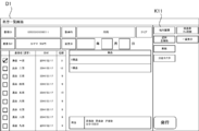
- the control unit 11 displays a prescription list screen D1 showing a list of drug payout data on the monitor 13. Then, when the prescription expansion key K11 is operated by selecting arbitrary drug payout data while the prescription list screen D1 is displayed, the control unit 11 inputs the prescription as shown in FIG. The screen D2 is displayed on the monitor 13. After that, the control unit 11 selects drug information corresponding to any drug to be assigned to the variable tablet cassette 22 in response to a user operation on the prescription input screen D2.
- the control unit 11 corresponds to the operation key K21.
- An operation screen (not shown) for selecting the hand-spreading unit 4 or the variable tablet cassette 22 as a drug supply form of the drug information to be used is displayed.
- the control unit 11 determines that the cassette selection start operation has been performed, and shifts the process to step S2. ..
- the operation screen (not shown) is omitted, and the variable tablet cassette 22 and the hand-spreading unit 4 can be arbitrarily selected as the allocation destination of the drug information on the cassette selection screen D3 (see FIG. 18) described later. It is also possible that
- step S2 the control unit 11 executes a manual allocation process for selecting the variable tablet cassette 22 to which the drug information is assigned according to the user operation.
- a manual allocation process for selecting the variable tablet cassette 22 to which the drug information is assigned according to the user operation.
- step S111 the control unit 11 causes the monitor 13 to display a cassette selection screen D3 for selecting the variable tablet cassette 22.
- FIG. 18 is a diagram showing an example of the cassette selection screen D3.
- the specific region K31 corresponding to each of the fixed tablet cassettes 21 mounted on the mounting portion 211 and the specific region K32 corresponding to each of the variable tablet cassettes 22 mounted on the mounting portion 221 are arranged. It is displayed.
- the specific area K31 corresponding to the fixed tablet cassette 21 is displayed in a total of 54 units of 6 vertical units ⁇ 9 horizontal units, and the specific area K32 corresponding to the variable tablet cassette 22 is vertically 1 below the specific area K31. A total of 4 units, 4 units x 4 units, are displayed. The size of the specific area K32 is larger than that of the specific area K31. Further, in each of the specific areas K31, drug information such as a drug name of the drug contained in the fixed tablet cassette 21 corresponding to each of the specific areas K31 is displayed.
- the control unit 11 may display information for identifying the currently assigned chemical, such as the chemical name of the chemical corresponding to the chemical information, on the cassette selection screen D3.
- the number of the specific area K31 and the specific area K32 displayed on the cassette selection screen D3 of FIG. 18 is the maximum number of displays.
- the display of the specific area K31 and the specific area K32 corresponding to the mounting portion 211 and the mounting portion 221 to which the fixed tablet cassette 21 or the variable tablet cassette 22 is not mounted may be omitted.
- a specific symbol such as a display frame may be displayed instead of the specific area K31 or the specific area K32. That is, each of the specific area K31 and the specific area K32 may be displayed in the same arrangement as the arrangement of the mounting unit 211 and the mounting unit 221.
- the specific area K31 corresponding to the fixed tablet cassette 21 may not be displayed, and only the specific area K32 corresponding to the variable tablet cassette 22 may be displayed.
- the control unit 11 can assign the drug information to the variable tablet cassette 22 that is not mounted on the mounting unit 221, the variable tablet registered in advance on the cassette selection screen D3. It is also conceivable as another embodiment that the identification information of the cassette 22 and the like are displayed in a list as selection targets.
- control unit 11 displays, in each of the specific areas K32, an allocation state indicating the allocation status of drug information for each of the specific areas K32.
- "unallocated” is displayed in the specific area K32 corresponding to the variable tablet cassette 22 to which drug information is not assigned.
- the drug information is not assigned because the specific area K32 is blank.
- the allocated area of the specific area K32 is displayed in blue, the unallocated area is displayed in red, and the state is identifiable by color.
- the drug information is already assigned to the specific area K32 corresponding to the variable tablet cassette 22 to which the drug information is assigned by displaying the drug name or the like corresponding to the assigned drug information. The fact that the information is given and the type of the assigned drug are displayed.
- "allocated” may be displayed in the specific area K32 corresponding to the allocated variable tablet cassette 22.
- step S112 the control unit 11 receives the selection operation of the specific area K32 on the cassette selection screen D3.
- the reception process is executed by the reception process unit 112. Specifically, when the operation unit 14 is a touch panel provided on the monitor 13, the control unit 11 accepts a touch operation of the specific area K32 on the monitor 13 as a selection operation of the specific area K32.
- the control unit 11 accepts the movement and click operation of the mouse pointer to the specific area K32 on the monitor 13 as the selection operation of the specific area K32.
- variable tablet cassette 22 to which the drug information has not been assigned at the present time it is possible to select not only the variable tablet cassette 22 to which the drug information has not been assigned at the present time, but also the variable tablet cassette 22 to which the drug information has already been assigned. On the other hand, it is also conceivable as another embodiment that only the variable tablet cassette 22 to which the drug information is not assigned can be selected.
- step S113 the control unit 11 determines whether or not the drug information has already been assigned to the variable tablet cassette 22 corresponding to the specific region K32 selected in step S112.
- the processing after step S113 is executed by the allocation processing unit 113 of the control unit 11.
- the process proceeds to step S114, and the selected variable tablet cassette 22 has already been assigned.
- the process proceeds to step S117.
- step S114 the control unit 11 allocates the drug information to the variable tablet cassette 22 corresponding to the specific region K32 determined to be selected in step S112. Specifically, the control unit 11 updates the content of the allocation information 121 so as to associate the drug information with the variable tablet cassette 22.
- step S115 the control unit 11 specifies the drive condition corresponding to the drug information to be paid out based on the drive correspondence information 122 (see FIG. 11), and the drive condition and the drug information are assigned.
- the cassette identification information of the variable tablet cassette 22 is transmitted to the control unit 61.
- the control unit 61 drives the variable tablet cassette 22 in accordance with the pre-driving conditions under the driving conditions in step S22 (see FIG. 15) described later.
- the control unit 11 when the variable tablet cassette 22 is driven according to the drive conditions by executing the process of step S115 may be regarded as the drive process unit according to the present invention.
- step S116 the control unit 11 causes the display unit 25 of the variable tablet cassette 22 to which the drug information is assigned in step S114 to display the drug information assigned to the variable tablet cassette 22.
- the manual allocation process is terminated. That is, the control unit 11 displays the allocation state of drug information to each of the variable tablet cassettes 22 in each of the variable tablet cassettes 22.
- the control unit 11 extracts information on a preset display item from the drug delivery data and displays it on the display unit 25.
- the display unit 25 displays the drug name (drug ID), the payout amount, and the JAN code (bar code) of the tablets assigned to the variable tablet cassette 22.
- Various information such as the patient name, the date and time of allocation, or the person in charge of allocation may be displayed on the display unit 25.
- the control unit 11 allocates drug information of the same drug as the drug corresponding to any of the plurality of fixed tablet cassettes 21 to the arbitrary variable tablet cassette 22 according to a user operation. It is also possible. In this case, the control unit 11 is set to use the variable tablet cassette 22 instead of the fixed tablet cassette 21 for dispensing the drug corresponding to the drug information. Further, when the fixed tablet cassette 21 corresponding to the drug information assigned to the variable tablet cassette 22 is present, the control unit 11 is in a shortage state in which the drug in the variable tablet cassette 22 is insufficient. Even in such a case, it is conceivable to execute the error notification without executing the payout from the fixed tablet cassette 21.
- Step S117> when it is determined that the drug information has already been assigned to the variable tablet cassette 22 (S113: Yes), in the following step S117, the control unit 11 sends the drug information to the variable tablet cassette 22. Execute error notification processing without executing allocation. For example, the control unit 11 sends a message indicating that the selected variable tablet cassette 22 has already been assigned, such as "drug information has already been assigned to the selected cassette". To display. Further, a message notifying the variable tablet cassette 22 to which the variable tablet cassette 22 can be assigned may be displayed, such as "Cassette XX can be used".
- control unit 11 prohibits the allocation of the drug information to the variable tablet cassette 22 and transfers the other drug information to the variable tablet cassette 22. Do not allocate. This prevents the correspondence between the variable tablet cassette 22 and the drug information from being erroneously updated.
- the allocation of the drug information to the variable tablet cassette 22 is released when the preset release conditions are satisfied, and the variable tablet cassette 22 is in an unallocated state.
- the unassignment condition is, for example, that the packaging operation based on the drug delivery data using the variable tablet cassette 22 is completed, and that the variable tablet cassette 22 is attached to the mounting portion 221 after the packaging operation is completed. It is conceivable that attachment / detachment is detected, or an operation for forcibly canceling the allocation of the drug information to the variable tablet cassette 22 is performed by a user operation.
- the attached / detached state of the variable tablet cassette 22 to the mounting unit 221 is detected by, for example, an optical sensor or a mechanical sensor (not shown) provided in the mounting unit 221 and input to the control unit 11.
- step S3 the control unit 11 determines whether or not there is a request for issuing drug payout data. Specifically, the control unit 11 determines that the issuance request for the drug withdrawal data has been made when the issuance operation for issuing the pre-registered drug withdrawal data is performed on the operation unit 14. ..
- the drug payout data is acquired from a higher-level system such as the prescription input terminal 200, or is input by the drug payout device 100.
- control unit 11 returns the process to the step S1 when there is no request to issue the drug payout data (No side of S3).
- the control unit 11 determines that there is a request to issue the drug delivery data (Yes side of S3), the control unit 11 shifts the process to step S4.
- the control unit 11 receives the drug payout data from a higher-level system such as the prescription input terminal 200, the drug payout data is issued without requiring the user to issue the drug. It may be determined that the request has been made and the process may be shifted to step S4.
- step S4 whether or not the fixed tablet cassette 21 or the variable tablet cassette 22 corresponding to all the drug information input as the drug information indicating the tablet to be dispensed by the drug payout data exists in the control unit 11.
- the control unit 11 does not have the corresponding fixed tablet cassette 21 based on the cassette master and the allocation information 121 stored in the storage unit 12, and the variable tablet cassette 22 does not exist. It is determined whether or not a drug not assigned to is included in the drug withdrawal data as a prescription drug.
- the cassette master is based on chemical information read from RFID tags (not shown) provided on each of the fixed tablet cassettes 21 by a reading device such as the RFID reader / writer 232 provided on each of the mounting portions 211. Is updated by the control unit 11. Further, the control unit 11 can display an edit screen for editing the cassette master on the monitor 13 and update the cassette master according to a user operation of the operation unit 14 on the edit screen. be.
- the control unit 11 shifts the process to step S41.
- a type of tablet that is not contained in the fixed tablet cassette 21 and is not assigned to the variable tablet cassette 22 is a tablet for which the variable tablet cassette 22 or the hand-spreading unit 4 needs to be assigned as the payout source of the tablet. Is.
- the type of tablet to which the variable tablet cassette 22 or the hand-spreading unit 4 needs to be assigned may be referred to as an allocation target tablet.
- the control unit 11 shifts the process to step S5.
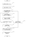
- step S41 the control unit 11 automatically transfers the drug information of the tablet to be allocated among the tablets to be dispensed shown in the drug delivery data to the variable tablet cassette 22 or the hand-spreading unit 4 which has not been assigned. Executes the automatic allocation process.
- the control unit 11 allocates the drug information of each of the allotted tablets to the variable tablet cassette 22 or the hand-spreading unit 4. Become.
- the control unit 11 allocates drug information of a plurality of the allotted tablets to any of the variable tablet cassette 22 and the hand-spreading unit 4.
- the drug information of the tablet having a smaller size among the tablets to be assigned is preferentially assigned to the variable tablet cassette 22.
- the control unit 11 allocates the drug information of the plurality of allotted tablets to either the variable tablet cassette 22 or the hand-spreading unit 4, the larger tablet among the allotted tablets
- the drug information is preferentially assigned to the hand-spreading unit 4.
- Step S411 the control unit 11 executes a process of identifying the variable tablet cassette 22 that is currently communicable (controllable) among the variable tablet cassettes 22. For example, the control unit 11 determines that the variable tablet cassette 22 of the variable tablet cassette 22 that has succeeded in reading information from the RFID tag 26 by the RFID reader / writer 245 is in a communicable state. That is, the control unit 11 identifies the variable tablet cassette 22 mounted on the mounting unit 221. As another embodiment, the step S411 may be omitted.
- Step S412> the control unit 11 assigns the unallocated variable tablet cassette 22 to which no drug information is currently assigned among the one or more variable tablet cassettes 22 specified in step S411. It is specified based on 121 (see FIG. 10).
- step S413 the control unit 11 determines that the number of types of tablets to be assigned that need to be assigned to either the variable tablet cassette 22 or the hand-spreading unit 4 is the unallocated tablet specified in step S412. It is determined whether or not there are more than the number of variable tablet cassettes 22. Then, when it is determined that the number of types of the allotted tablets is larger than the number of the unallocated variable tablet cassettes 22 (S413: Yes), the process proceeds to step S414. On the other hand, when it is determined that the number of types of the allotted tablets is not larger than the number of the unallocated variable tablet cassettes 22 (S413: No), the process proceeds to step S421.
- step S421 the control unit 11 allocates each of the allotted tablets to each of the unallocated variable tablet cassettes 22, and shifts the process to step S418.
- the control unit 11 updates the content of the allocation information 121 based on the correspondence between each of the drug information of the tablet to be assigned and each of the variable tablet cassette 22. Thereby, the control unit 11 can identify the variable tablet cassette 22 to which each of the drug information is assigned based on the allocation information 121.
- Step S414 On the other hand, when the number of types of the allotted tablets is larger than the number of the unallocated variable tablet cassettes 22 (S413: Yes), each of the allotted tablets cannot be assigned to the variable tablet cassette 22. Therefore, in the subsequent step S414, the control unit 11 identifies the tablet having the smallest tablet size among the allotted tablets that are not currently assigned to the variable tablet cassette 22. The control unit 11 can identify the tablet having the smallest tablet size among the unassigned tablet types based on the tablet size registered in the drug master.
- the control unit 11 controls the outer diameter of the tablet. Determine the size of a tablet based on size, surface area, or volume. For example, the control unit 11 identifies the tablet having the smallest total outer diameter dimension of the tablet as the smallest tablet. Further, the control unit 11 may specify the tablet having the smallest outer diameter dimension of the tablet as the smallest tablet. Further, the control unit 11 may specify the tablet having the smallest surface area or volume of the tablet as the smallest tablet.
- a preset size group to which the tablet belongs is registered in the drug master, and the control unit 11 may determine the size of the tablet based on the size group.
- the size group can be considered to have four stages of large, medium, small, and extremely small.
- the configuration for the control unit 11 to determine the size of the tablet is not limited to that described here, and other methods may be used.
- step S415 the drug information of the allotted tablet identified as the smallest tablet in step S414 is assigned to the unallocated variable tablet cassette 22. That is, the drug information of the tablet having the smallest size among the tablets to be assigned, which is not currently assigned to the variable tablet cassette 22, is preferentially assigned to the variable tablet cassette 22.
- the control unit 11 updates the content of the allocation information 121 based on the correspondence between the drug information and the variable tablet cassette 22. Thereby, the control unit 11 can identify the variable tablet cassette 22 to which each of the drug information is assigned based on the allocation information 121.
- step S415 the control unit 11 assigns the RFID reader / writer 245 to the RFID tag 26 of the variable tablet cassette 22 to which the drug information is assigned by controlling the RFID reader / writer 245. Record the drug information obtained.
- the control unit 11 converts various information such as the tablet withdrawal amount, the patient name, the assigned date and time, the name of the pharmacist in charge, and the prescription identification information indicated by the drug information into the drug withdrawal data together with the drug information. It is also possible to record based on.
- the drug information is not recorded on the RFID tag 26 of the variable tablet cassette 22.
- the cassette identification information is recorded in advance on the RFID tag 26, and the RFID reader / writer 245 is an RFID reader capable of only reading the information.
- the control unit 11 can recognize the drug information assigned to the variable tablet cassette 22 based on the cassette identification information read from the RFID tag 26 and the allocation information 121. be.
- step S416 the control unit 11 determines whether or not the unallocated variable tablet cassette 22 remains.
- the process is returned to step S414.
- the drug tablets of the tablets having a smaller size are preferentially assigned to the variable tablet cassette 22 in order.
- the process proceeds to step S417.
- step S417 the control unit 11 allocates the drug information of the tablet to be assigned that was not assigned to the variable tablet cassette 22 to the hand-spreading unit 4.
- the control unit 11 allocates the drug information of the plurality of tablets to the hand-spreading unit 4. become. In this way, the control unit 11 preferentially allocates the drug information of the small-sized tablet to the variable tablet cassette 22, and allocates the drug information of the large-sized tablet to the hand-spreading unit 4.
- the control unit 11 allocates the tablet to be assigned to the variable tablet cassette 22 with priority given to the tablet having the smallest tablet size. Therefore, the user who puts the tablets into the drug dispensing device 100 may put the tablets of a relatively large size into the hand-spreading unit 4 and put the tablets of a relatively small size into the variable tablet cassette 22. The tablet loading operation can be performed efficiently.
- step S418 the control unit 11 specifies the drive condition corresponding to the drug information to be paid out based on the drive correspondence information 122 (see FIG. 11), and the drive condition is described in the same manner as in step S115. And the cassette identification information of the variable tablet cassette 22 to which the drug information is assigned are transmitted to the control unit 61.
- each of the mounting portions 221 is provided with a cassette lock portion that can lock the removal of each of the variable tablet cassettes 22.
- the cassette lock unit includes a drive unit such as a solenoid or a motor, and a regulation unit that is driven by the drive unit and can regulate the removal of the variable tablet cassette 22 from the mounting unit 221.
- a drive unit such as a solenoid or a motor
- a regulation unit that is driven by the drive unit and can regulate the removal of the variable tablet cassette 22 from the mounting unit 221.
- the control unit 61 controls the drive unit of the cassette lock unit of each of the mounting units 221 based on the control instruction from the control unit 11, thereby individually determining whether or not the variable tablet cassette 22 is locked. It is possible to control. Specifically, when the drug information is assigned to the variable tablet cassette 22 in step S2 or step S41, the control unit 11 transmits a lock instruction of the variable tablet cassette 22 to the control unit 61. As a result, the control unit 61 drives the regulation unit of the cassette lock unit of the mounting unit 221 to which the variable tablet cassette 22 to which the drug information is assigned is mounted, and takes out the variable tablet cassette 22. Regulate operation.
- control unit 11 or the control unit 61 when restricting the take-out operation of the variable tablet cassette 22 is an example of the regulation processing unit according to the present invention. Further, the transmission of the driving condition in the step S2 or the step S42 may also serve as the lock instruction.
- the control unit 61 controls the unlock instruction of the variable tablet cassette 22. It is transmitted to unit 61. As a result, the control unit 61 drives the regulation unit of the cassette lock unit of the mounting unit 221 to which the variable tablet cassette 22 to which the input drug information is assigned is mounted, and the variable tablet cassette. The restriction on the removal of 22 is lifted. That is, when the specific release operation is performed, the variable tablet cassette 22 can be removed, and the variable tablet cassette 22 can be replenished with chemicals.
- control unit 11 or the control unit 61 when the restriction on the taking-out operation of the variable tablet cassette 22 is released in response to the specific release operation is an example of the release processing unit according to the present invention.
- replenishment of an erroneous drug to the variable tablet cassette 22 to which the drug information is assigned is suppressed, and the variable tablet cassette 22 to which the drug information is not assigned can be freely attached and detached. It becomes.
- the bar code reader 7 reads the drug information indicating the same drug as the drug information assigned to the variable tablet cassette 22, or the drug information is read by the operation unit 14. It is to be input and so on. Further, when a predetermined operation unit such as an operation button is provided corresponding to each of the mounting units 221 and a specific release operation such as a long press operation is performed on the predetermined operation unit, the above-mentioned The control unit 61 may unlock the variable tablet cassette 22 in the mounting unit 221.
- control unit 11 is assigned to the variable tablet cassette 22 after the specific release operation for the variable tablet cassette 22 is performed using the predetermined operation unit or the operation unit 14.
- the unlock instruction of the variable tablet cassette 22 is transmitted to the control unit 61.
- the control unit 61 unlocks the variable tablet cassette 22 to which the drug information of the tablet read by the barcode reader 7 is assigned.
- the control unit 11 does not complete the operation of changing the drive condition of the variable tablet cassette 22 based on the drive condition from the control unit 61. It is also conceivable that the variable tablet cassette 22 is not unlocked.
- step S419 the control unit 11 similarly to the display unit 25 of the variable tablet cassette 22 to which the drug information was assigned in the step S41, the drug information assigned to the variable tablet cassette 22. Is displayed. That is, the control unit 11 displays the allocation state of drug information to each of the variable tablet cassettes 22 in each of the variable tablet cassettes 22.
- the control unit 11 displays the allocation state of drug information to each of the variable tablet cassettes 22 in each of the variable tablet cassettes 22.
- the user recognizes the variable tablet cassette 22 as a tablet charging target corresponding to the drug information and the tablet supply unit. It can be removed from 2.
- the user attaches the variable tablet cassette 22 to the tablet supply unit 2.
- Step S21> On the other hand, as shown in FIG. 15, in the packaging control unit 6, the control unit 61 determines in step S21 whether or not the drive condition is received from the control unit 11. Here, when the drive condition is received (Yes side of S21), the control unit 61 shifts the process to step S22, and while the drive condition is not received (No side of S21). , The process shifts to step S23.
- the control unit 61 stores the driving condition received from the control unit 11 in the storage unit 62 in association with the cassette identification information of the variable tablet cassette 22 to which the drug information is assigned.
- step S22 the control unit 61 drives the variable tablet cassette 22 to which the drug information is assigned according to the driving conditions corresponding to the drug information, and releases the tablet corresponding to the drug information from the variable tablet cassette 22. Make it payable.
- the variable tablet cassette 22 corresponding to the cassette identification information received together with the driving conditions is driven according to the pre-driving conditions among the driving conditions, and the height of the payout path and the width of the payout path.
- the control unit 61 is variable according to the pre-driving condition (height and width of the payout path).
- the tablet cassette 22 is driven, and then the tablet is dispensed from the variable tablet cassette 22 (S24).
- control unit 61 controls the height adjusting unit 226A and the width adjusting unit 227A according to the driving conditions to determine the types of tablets that can be dispensed from the variable tablet cassette 22 in units of one tablet. Change to the tablet indicated by the drug information assigned in step S2 or S41.
- the control unit 61 returns the positions of the height regulating member 226 and the width regulating member 227 to the initial state by driving the drive motor 243 and the drive motor 244.
- the control unit 61 drives the height adjusting unit 226A by the drive motor 243, and determines the height h1 regulated by the height regulating member 226 of the variable tablet cassette 22 under the driving conditions. The height is changed to the height of the payout route.
- control unit 61 drives the width adjusting unit 227A by the drive motor 244, and the width w1 regulated by the width regulating member 227 of the variable tablet cassette 22 is defined by the driving conditions. Change to the width of the payout route.
- the control unit 61 drives the drive motor 243 and the drive motor 244 based on the detection result. do it.
- the tablets indicated by the drug information assigned in step S2 or S41 are in units of one tablet. It becomes possible to pay out, and the amount of the tablet to be paid out can be controlled.
- the control unit 61 when executing the process (drive control step) of step S22 is an example of the drive processing unit.
- variable tablet cassette 22 is not mounted on the mounting portion 221 when the drug information is assigned to the variable tablet cassette 22.
- step S22 the variable tablet cassette 22 cannot be driven according to the pre-driving conditions. Therefore, the control unit 61 stores the flag information indicating whether or not the driving condition received from the control unit 11 is reflected in the variable tablet cassette 22 in the storage unit 62 and updates it at any time. Then, the control unit 61 refers to the flag information at the start of the packaging operation in step S24 described later, and the driving conditions are not reflected in the variable tablet cassette 22 used in the packaging operation. The variable tablet cassette 22 is driven according to the pre-driving condition before the packaging operation is executed, and the height h1 and the width w1 of the payout path are changed.
- the driving condition does not include the pre-driving condition
- the height adjusting portion 226A and the width adjusting portion 227A of the variable tablet cassette 22 are manually operated to obtain the height h1 of the payout path and the height h1 of the payout path.
- a configuration in which the width w1 can be arbitrarily adjusted is also considered as another embodiment.
- the user adjusts the height h1 and the width w1 of the payout path of the variable tablet cassette 22, and then mounts the variable tablet cassette 22 on the mounting portion 221 of the tablet supply unit 2.
- the height adjusting unit 226A and the width adjusting unit 227A have a configuration that can be operated by a rotation operation using a tool such as a screwdriver, for example.
- step S5 the control unit 11 has the number of chemicals to be charged into the variable tablet cassette 22, the hand-spreading unit 4, the powder supply unit 3, and the like based on the chemical dispensing data.
- the input guide screen D4 (see FIGS. 23 and 24) showing the amount and the like is displayed on the monitor 13.
- the user refers to the display content of the monitor 13 and inputs a necessary number or amount of chemicals to the variable tablet cassette 22, the hand-spreading unit 4, the powder supply unit 3, and the like.
- the display of the closing guide screen D4 in step S5 is executed by the display processing unit 111 of the control unit 11.
- step S6 the control unit 11 inputs the chemicals required for the packaging operation executed based on the chemical delivery data to the variable tablet cassette 22, the powder supply unit 3, the hand-spreading unit 4, and the like. It is determined whether or not the charging completion operation indicating that the operation has been completed has been performed on the operation unit 14.
- the charging completion operation includes a pressing operation of the charging completion operation button provided on the chemical dispensing device 100, a touch operation of the operation key K23 (see FIGS. 23 and 24) displayed on the charging guide screen D4, and the like. Is.
- the control unit 11 makes the process wait in the step S6 until the closing operation is performed (S6: No). On the other hand, when it is determined that the closing operation has been performed (S6: Yes), the control unit 11 shifts the process to step S7.
- step S7 the control unit 11 transmits a request to start the packaging operation based on the drug delivery data to the control unit 61.
- step S7 when the user performs a packaging operation start request operation, the packaging operation start request may be transmitted to the control unit 61.
- the control unit 11 makes a start request for the tablet packaging operation of the tablet that does not exist in the fixed tablet cassette 21, for example, by the following procedure. Send.
- the control unit 11 reads the cassette identification information of the variable tablet cassette 22 from the RFID tag 26 of the variable tablet cassette 22 mounted on each of the mounting units 221 and is currently mounted on each of the mounting units 221.
- the variable tablet cassette 22 is specified.
- the control unit 11 can specify the variable tablet cassette 22 mounted on each of the mounting units 221. Therefore, the user can mount each of the variable tablet cassettes 22 on the arbitrary mounting unit 221. Is possible.
- the plurality of drug information is assigned to the plurality of variable tablet cassettes 22, and after each of the variable tablet cassettes 22 is removed, the variable tablet cassettes 22 are mounted by switching the mounting locations.
- control unit 11 can determine the mounting unit 221 to which each of the variable tablet cassettes 22 is mounted. If the variable tablet cassette 22 is mounted on the mounting section 221 which is different from the mounting section 221 when the drug information is assigned to the variable tablet cassette 22, the packaging operation is not started as an error. Can also be considered as another embodiment.
- the control unit 11 sets each of the variable tablet cassettes 22 containing the tablets indicated by the drug information shown in the drug withdrawal data among the variable tablet cassettes 22. It is specified based on the allocation information 121. After that, the control unit 11 sets the cassette identification information of the variable tablet cassette 22 to which the drug information is assigned, and the mounting to which the variable tablet cassette 22 is mounted, for each of the drug information shown in the drug delivery data.
- a start request including the identification information of the unit 221 and the information necessary for the packaging operation based on the drug withdrawal data such as the prescription amount of the tablet corresponding to the drug information for each administration time is transmitted to the control unit 61.
- drug information about the powder to be dispensed from the powder supply unit 3 information such as the number of sachets, the prescription amount for each time of administration, and the drug for the tablet to be dispensed from the hand-spreading unit 4.
- Information such as information and the number of tablets at each time of administration is also included.
- the drug withdrawal data may be included in the start request.
- Step S23> On the other hand, as shown in FIG. 15, in the packaging control unit 6, the control unit 61 determines in step S23 whether or not there is a request from the control unit 11 to start the packaging operation. Here, when the control unit 61 receives the request to start the packaging operation (Yes side of S23), the control unit 61 shifts the process to step S24, and the request to start the packaging operation is not received. In the meantime (No side of S23), the process shifts to step S24.
- step S24 the control unit 61 dispenses necessary chemicals by the tablet supply unit 2, the powder supply unit 3, and the hand-spreading unit 4 in accordance with the request for starting the packaging operation, and the packaging unit 5 delivers the necessary chemicals.
- the processing is an example of the drive processing unit according to the present invention
- the control unit 61 when executing the drive step is an example of the drive processing unit according to the present invention. Since the control of the powder supply unit 3, the hand-spreading unit 4, and the packaging unit 5 may be the same as in the conventional case, the description thereof is omitted here, and only the tablet dispensing operation by the tablet supply unit 2 is omitted. Will be described.
- control unit 61 dispenses tablets from the variable tablet cassette 22 with respect to the tablet supply unit 2 according to the driving conditions corresponding to the drug information assigned to the variable tablet cassette 22 in the step S2 or S41.
- the rotation speed of the drive motor 242 of the second drive unit 24 driven by is changed. That is, the rotation speed of the second rotating body 224 when the tablet is dispensed from the variable tablet cassette 22 is changed, and the tablet ejection speed from the variable tablet cassette 22 is changed according to the type of the tablet. ..
- the control unit 61 drives the drive motor 241 and the drive motor 242 corresponding to the variable tablet cassette 22 to which the drug information to be dispensed is assigned, and drives the first rotating body 223 and the second.
- the tablet is dispensed by rotating the rotating body 224.
- the control unit 61 drives the drive motor 242 according to the payout speed defined as the drive condition corresponding to the chemical information in the drive correspondence information 122.
- the control unit 61 drives the variable tablet cassette 22 according to the driving condition (delivery speed).
- the tablet is dispensed from the variable tablet cassette 22.
- variable tablet cassette 22 does not include the height regulating member 226 and the width regulating member 227, it is conceivable to change only the tablet dispensing speed from the variable tablet cassette 22. Further, the drive speed of the drive motor 241 may be constant or may be changed depending on the type of tablet.
- the control unit 61 detects the number of tablets discharged from the variable tablet cassette 22 by the optical sensor 225A provided at the discharge port 225 of the variable tablet cassette 22. Count based on. As a result, the control unit 61 controls the drive of the variable tablet cassette 22 based on the number of tablets discharged using the optical sensor 225A, and only a preset payout amount (prescription amount) is obtained. It can be dispensed from the variable tablet cassette 22.
- the optical sensor 225A is provided at the outlet 225, and as shown in FIG. 20A, a light emitting unit 225B that irradiates light and a light receiving unit 225C that detects light reception. It is a transmissive optical sensor having. As another embodiment, the optical sensor 225A may be a reflection type optical sensor.
- the optical sensor 225A the presence or absence of blocking of the optical path changes depending on whether or not a tablet is present in the optical path between the light emitting unit 225B and the light receiving unit 22C, and is output from the optical sensor 225A.
- the detection signal changes.
- the optical sensor 225A outputs ON as a detection signal when light is detected by the light receiving unit 225C, and outputs OFF as a detection signal when light is not detected by the light receiving unit 225C.
- the relationship between ON and OFF may be opposite.
- control unit 61 determines the passage of the tablet based on the detection signal input from the optical sensor 225A.
- the control unit 61 determines the passage of the tablet based on the detection signal input from the optical sensor 225A.
- the tablet passing on the optical path of the optical sensor 225A has a high transmittance such as transparent or translucent, the counting accuracy of the number of the tablet by the optical sensor 225A may decrease. ..
- FIGS. 20A to 20F in the process in which the tablet M1 having a low transmittance that is not transparent or translucent passes through the light emitting portion 225B and the light receiving portion 225C.
- the detection signal output from the optical sensor 225A changes as shown in FIG. 20 (G). That is, the light L1 emitted from the light emitting unit 225B receives the light L1 before and after the tablet M1 passes through the light emitting unit 225B and the light receiving unit 225C (see FIGS. 20A and 20F). It is incident on the portion 225C.
- the tablet M1 passes between the light emitting unit 225B and the light receiving unit 225C (see FIGS.
- the control unit 11 can accurately detect that one tablet M1 has passed based on the detection signal.
- the optics of the transparent or translucent tablet M2 having high transmittance in the process of passing through the light emitting portion 225B and the light receiving portion 225C changes as shown in FIG. 21 (G). That is, the light L1 emitted from the light emitting unit 225B receives the light L1 before and after the tablet M2 passes through the light emitting unit 225B and the light receiving unit 225C (see FIGS. 21A and 21F). It is incident on the portion 225C. Further, while the tablet M2 passes between the light emitting unit 225B and the light receiving unit 225C (see FIGS.
- the light L1 emitted from the light emitting unit 225B is the tablet. It may pass through M2 and enter the light receiving unit 225C.
- the light L1 emitted from the light emitting unit 225B is the tablet. It may not be incident on the light receiving portion 225C because it is blocked by the edge portion of M2.
- the detection signal output from the optical sensor 225A may change a plurality of times between OFF and ON.
- the control unit 11 may erroneously detect that a plurality of tablets M2 have passed. For example, if the detection signal output from the optical sensor 225A changes twice between OFF and ON, the control unit 11 may erroneously detect that two tablets M2 have passed based on the detection signal. There is sex.
- the control unit 11 counts the number of tablets based on the detection signal until a preset specific time elapses after the detection signal of the optical sensor 225A changes between OFF and ON. It is conceivable not to carry out.
- the specific time is a preset time as a time required from when the tablet starts to pass through the optical sensor 225A until it completely passes through the optical sensor 225A.
- the first time is counted based on the change in the detection signal of the above, and when the detection signal changes from the second time onward, it is not counted as the number of tablets and is ignored.
- the control unit 11 changes the specific time depending on the type of tablet dispensed from the variable tablet cassette 22.
- the control unit 11 associates the tablet or the size of the tablet to be dispensed from the variable tablet cassette 22 with the specific time preset as the time required for the tablet to pass through the optical sensor 225A. Based on the corresponding data obtained, the specific time to be used when counting tablets is determined. Further, the control unit 11 may calculate the specific time based on the tablet size and the tablet dispensing speed by the variable tablet cassette 22. The specific time may be commonly used as the specific time corresponding to the maximum size of tablets that can be dispensed by the variable tablet cassette 22 as the specific time corresponding to all types of tablets.
- control unit 61 from the variable tablet cassette 22 according to the set values of the first slowdown and the second slowdown defined as the drive conditions corresponding to the drug information in the drive correspondence information 122. Performs tablet payout stop control.
- the control unit 61 finishes dispensing the prescribed amount defined in the chemical dispensing data.
- the drive of the variable tablet cassette 22 is stopped according to the first slowdown and the second slowdown, which are the conditions for stopping the drive.
- the control unit 61 determines that the remaining number of locks in the payout amount has reached “6 locks” based on the number of locks counted using the optical sensor 225A provided at the payout outlet 225. If so, the rotation speed of the drive motor 242 is reduced to the first rotation speed. After that, the control unit 61 determined that the remaining number of locks in the payout amount reached "1 lock” based on the number of locks counted using the optical sensor 225A provided at the payout outlet 225. In this case, the rotation speed of the drive motor 242 is further reduced to the second rotation speed.
- the specific time may be extended according to the deceleration of the rotation speed.
- control unit 61 executes stop control of tablet dispensing from the variable tablet cassette 22 according to the presence or absence of the reverse rotation operation defined as the drive condition corresponding to the drug information in the drive correspondence information 122. do.
- control unit 11 when executing the processing is an example of the drive processing unit.
- the control unit 61 finishes dispensing the prescribed amount defined in the chemical dispensing data.
- the driving of the variable tablet cassette 22 is stopped.
- the control unit 61 makes the second rotation when stopping the dispensing of tablets from the variable tablet cassette 22.
- a reverse rotation operation for switching the transport direction of the state by the body 224 in the reverse direction is executed. For example, when the number of locks counted by the optical sensor 225A provided at the payout port 225 reaches the payout amount, the control unit 61 sets the drive motor 242 for a predetermined time set in advance. Rotate in the reverse direction. As a result, when a tablet that easily rolls is placed on the second rotating body 224, the tablet is prevented from being excessively discharged from the payout port 225.
- An opening / closing shutter is provided at the payout outlet 225, and the opening / closing shutter is closed when the number of locks counted by the control unit 61 using the optical sensor 225A reaches the payout amount. It may be.
- the control unit 61 does not need the reverse rotation when stopping the dispensing of tablets from the variable tablet cassette 22. Do not perform any action.
- the timing for starting the reverse rotation operation may be when the number of locks counted by the control unit 61 using the optical sensor 225A reaches a value that is a predetermined number less than the payout amount. ..
- the predetermined number corresponding to each chemical information may be stored in advance in the drive correspondence information 122.
- the reverse rotation operation can be started before the number of tablets counted by the control unit 61 using the optical sensor 225A reaches the payout amount, and the extra tablets from the payout outlet 225 can be started. It is possible to prevent a large amount of payout. Further, after the number of tablets counted by the control unit 61 using the optical sensor 225A reaches a value smaller than the payout amount by the predetermined number, the reverse rotation operation is performed every time one tablet is paid out. Is conceivable to start.
- step S42 the case where the height h1 of the height regulating member 226 and the width w1 of the width regulating member 227 in the variable tablet cassette 22 in the variable tablet cassette 22 are changed according to the driving conditions will be described as an example in step S42. bottom.
- the control unit 61 executes the height h1 of the height regulating member 226 and the width w1 of the width regulating member 227 immediately before the start of the packaging operation. That is, the reflection of the pre-driving condition on the variable tablet cassette 22 may be executed at an arbitrary timing until the packaging operation is started.
- Step S25> After that, when the packaging operation in the step S24 is completed, the control unit 61 transmits a completion notification of the packaging operation to the control unit 11 in the subsequent step S25.
- step S8 the control unit 11 is waiting for the completion notification of the packaging operation from the control unit 61 (No side of S8). Then, when the completion notification of the packaging operation is received (Yes side of S8), the control unit 11 shifts the process to step S9.
- step S9 the control unit 11 displays on the display unit 25 of the variable tablet cassette 22 that the payout has been completed to the effect that the payout has been completed. For example, in step S9, it is conceivable that the characters “payment completed” are displayed on the display unit 25, or the display of the drug information on the display unit 25 is erased.
- the control unit 11 receives the notification of the completion of the packaging operation, the control unit 11 releases the allocation of the drug information to the variable tablet cassette 22 that has been performed for the packaging operation. Further, the control unit 11 provides the drug information for the variable tablet cassette 22 when the variable tablet cassette 22 is attached to or detached from the mounting unit 221 after the payout to the display unit 25 of the variable tablet cassette 22 is completed. May be deallocated.
- the control unit 11 preferentially assigns drug information of a tablet having a smaller tablet size to the variable tablet cassette 22 among a plurality of types of tablets to be dispensed. ..
- the user can put the tablets having a relatively small size into the variable tablet cassette 22 together. Therefore, according to the drug dispensing device 100, the variable tablet cassette 22 and the hand-spreading unit 4 can be used in consideration of the work efficiency of the user.
- control unit 11 of the prescription control unit 1 executes the allocation of the drug information to the variable tablet cassette 22
- control unit 61 of the packaging control unit 6 may execute the allocation of the drug information to the variable tablet cassette 22.
- various information such as the drug master, the cassette master, the allocation information 121, and the drive correspondence information 122 are stored in the storage unit 62 of the packaging control unit 6.
- the control unit 61 automatically performs the above based on various information stored in the storage unit 62.
- the drug information included in the drug withdrawal data is assigned to the variable tablet cassette 22, or the drug information is assigned to the variable tablet cassette 22 according to a user operation.
- the control unit 61 responds to the user's operation with the variable tablet cassette 22 and the drug information.
- a configuration in which the allocation relationship with and can be changed is also conceivable.
- the allocation information 121 can be edited by the control unit 61 accessing the storage unit 12.
- the allocation information 121 may be stored in both the storage unit 12 and the storage unit 62 and synchronized in real time.
- the height regulating member 226 and the width regulating member 227 of the variable tablet cassette 22 can be adjusted in all the mounting portions 221 and the RFID reader / writer is attached to all the mounting portions 221.
- the case where 245 is provided has been described.
- the height regulating member 226 and the width regulating member 227 of the variable tablet cassette 22 can be adjusted by any one or a plurality of the mounting portions 221 of the mounting portions 221.
- the RFID reader / writer 245 may be provided on the mounting portion 221.
- each of the mounting portions 221 apart from each of the mounting portions 221, a mounting portion dedicated to adjustment for adjusting the height regulating member 226 and the width regulating member 227 of the variable tablet cassette 22 is provided, and the mounting portion is provided with the mounting portion.
- An RFID reader / writer 245 may be provided. This makes it possible to simplify the configuration of each of the mounting portions 221.
- the control unit 11 assigns the drug information to the mounting unit 221 and indirectly allocates the drug information to the variable tablet cassette 22.
- the allocation information 121 is attached to the attachment portion 221 identification information (A1 to A4, etc.), the drug ID (drug identification information), and the attachment portion 221.
- the identification information (C1, C3, etc.) of the variable tablet cassette 22 is stored in association with each other.
- the control unit 11 grasps the chemicals assigned to the mounting unit 221 and the variable tablet cassette 22 mounted on the mounting unit 221 and executes the packaging operation on the chemical dispensing device 100. It is possible to make it.
- the allocation processing unit 113 of the control unit 11 provides drug information of the tablet having the smaller size among the plurality of types of tablets to be paid out in the automatic allocation process (see FIG. 14). It may be preferentially assigned to the mounting portion 221.
- the user can collectively put the tablets having a relatively small size into the variable tablet cassette 22 which can be attached to and detached from the mounting portion 221. Therefore, according to the drug dispensing device 100, the variable tablet cassette 22 and the hand-spreading unit 4 can be used in consideration of the work efficiency of the user.
- the tablet to be assigned may be assigned to the variable tablet cassette 22.
- the drug dispensing device 100 determines that the number of tablets to be dispensed based on the drug dispensing data cannot be accommodated in the variable tablet cassette 22 with respect to the tablet to be allocated in the packaging operation based on the drug dispensing data. It has a plurality of cassette allocation functions for assigning drug information of the tablet to be assigned to the plurality of variable tablet cassettes 22. As a result, in the drug dispensing process, the drug dispensing device 100 can dispense the required amount of the allotted tablet in order from each of the variable tablet cassettes 22 in the packaging operation based on the drug dispensing data. ..
- the control unit 11 determines the allocation target tablet in units of one tablet based on the volume of the variable tablet cassette 22 and the volume of the allocation target tablet in preset units of one tablet. When the value obtained by multiplying the volume of the allotted tablet by the number of tablets to be dispensed is equal to or less than the volume of the variable tablet cassette 22, it may be determined that the allotted tablet cannot be accommodated in the variable tablet cassette 22. good.
- the user can put the allotted tablet into the plurality of variable tablet cassettes 22 at a time. This makes it possible, and it is not necessary to replenish the tablet to be assigned during the tablet dispensing operation by the drug dispensing device 100, and the work efficiency is improved.
- the display processing unit 111 of the control unit 11 indicates the number or amount of chemicals to be charged into the variable tablet cassette 22, the hand-spreading unit 4, the powder supply unit 3, and the like. It is provided with a closing guide display function for displaying the closing guide screen D4 on the monitor 13.
- a closing guide display function for displaying the closing guide screen D4 on the monitor 13.
- tablets in the packaging operation executed based on the drug dispensing data, tablets may be dispensed from the variable tablet cassette 22 and powder may be dispensed by the powder supply unit 3.
- the control unit 11 determines the number of tablets to be charged into the variable tablet cassette 22 and the powder supply unit 3 as the amount of chemicals required for the packaging operation executed based on the drug delivery data.
- the amount of powder to be charged is displayed on the charging guide screen D4.
- the maximum number of packages the upper limit of the number of drug packages that can be dispensed from the powder unit 3 by inputting the powder into the powder unit 3 once.
- the maximum number of packages the upper limit of the number of drug packages that can be dispensed from the powder unit 3 by inputting the powder into the powder unit 3 once.
- the total number of powder packages in the packaging operation executed by the powder supply unit 3 based on the drug dispensing data is the maximum number of packages in the powder supply unit 3. May exceed.
- the powder dispensing operation is required again in the middle of the packaging operation.
- the packaging operation is executed based on the drug withdrawal data, even if a plurality of loading operations are required for powdered medicine, all the required number of tablets at one time can be obtained. It may be sufficient to put it in the chemical dispensing device 100. Specifically, even when the number of packages in the package operation exceeds the maximum number of packages in the powder supply unit 3, the amount of the tablet dispensed in the package operation is the maximum of the variable tablet cassette 22. The number of tablets that can be stored may not be exceeded. In such a case, it is conceivable that the amount of the tablet and the powder to be added is displayed on the charging guide screen D4 for each charging operation of the required number of times for the powder.
- the number of packages in the packaging operation executed based on the drug delivery data is 186
- the maximum number of packages in the powder supply unit 3 is 100
- the number of tablets is 186. It is assumed that the number of tablets can be accommodated in the variable tablet cassette 22.
- the input amount for 100 packets and the input amount for 86 packets are displayed for the powder, and similarly for the tablets, the input amount for 100 packets and the input amount for 86 packets are displayed. It is possible that the quantity and is displayed.
- the user can perform the tablet loading operation. This may be done multiple times in vain, resulting in poor work efficiency.
- the display processing unit 111 of the control unit 11 performs a charging operation to the chemical dispensing device 100 among the chemicals dispensed from the chemical dispensing device 100 based on the chemical dispensing data.
- the corresponding injection amount is displayed for each injection operation.
- the powder dispensed from the powder supply unit 3 is the first-class chemical.
- the display processing unit 111 is concerned with the second type of chemicals that can be charged to the chemical dispensing device 100 at one time.
- the input amount corresponding to one input operation or the information for suggesting the input amount is displayed.
- the tablet dispensed from the variable tablet cassette 22 is an example of the second type of drug.
- the prescription control unit 1 including the control unit 11 that functions as the display processing unit 111 that executes such display processing is an example of the display control device according to the present invention.
- the information for suggesting the input amount is, for example, a message for instructing that the total amount of the number of tablets is input by looking at the prescription for the second type of drug.
- the first type of drug is a powder that is dispensed from the powder dispensing unit 3, and the total number of packages of the powder based on the drug dispensing data exceeds the maximum number of packets that are packaged by the powder dispensing unit 3.
- the case where the powdered drug of the second type is a tablet dispensed from the variable tablet cassette 22 will be described as an example.
- FIG. 22 is a flowchart showing another example of the chemical dispensing process. The description of the same treatment as that shown in FIG. 12 will be omitted.
- step S51 is executed in place of the step S5 in the chemical dispensing process shown in FIG. 12, and steps S81 to S82 are added.
- step S51 the control unit 11 displays the closing guide screen D4 in the same manner as in step S5.
- step S51 first, the control unit 11 needs to add the chemical to the chemical dispensing device 100 a plurality of times in the packaging operation based on the chemical dispensing data. Determine if one type of drug is included.
- the control unit 11 determines that the drug withdrawal data includes the drug of the first type, the first type of drug is required to execute the packaging operation a plurality of times.
- the charging amount corresponding to the first charging operation is displayed on the charging guide screen D4.
- the control unit 11 determines the second type of chemical. Displayes the charging amount corresponding to the one charging operation on the charging guide screen D4. Specifically, for the first type of chemicals, the total dispensed amount of the chemicals specified based on the chemicals withdrawal data is displayed separately for each charging operation, and for the second type of chemicals, the chemicals are said.
- the total payout amount of the drug specified based on the payout data is displayed.
- the user refers to the charging guide screen D4 displayed in step S51, and charges the first type of chemicals in the amount corresponding to the first charging operation into the chemical dispensing device 100, and at the same time, With respect to the second type of chemicals, the amount to be charged corresponding to one charging operation is charged into the chemical dispensing device 100.
- the control unit 11 executes the packaging operation for each of the second type of drugs in the same manner as in step S5.
- the charging amount corresponding to the one-time charging work required for the above is displayed on the charging guide screen D4.
- the user charges the second type of chemicals in the amount required for the packaging operation into the chemical dispensing device 100.
- step S81 the control unit 11 determines whether or not the timing for adding the chemical has arrived. Specifically, in the chemical dispensing device 100, when the chemicals to be dispensed in the packaging operation are insufficient, it is determined that the timing for charging the chemicals has arrived. Further, in the chemical dispensing device 100, the charging timing of the chemicals arrives when the packaging operation of the number of packages corresponding to the charging amount of the first type chemicals charged in the first charging operation is completed. You may judge that you have done so.
- step S81: Yes when it is determined that the injection timing of the chemical has arrived (S81: Yes), the process shifts to step S82, and it is determined that the injection timing of the chemical has not arrived (S81: No). , The process proceeds to step S8.
- step S8: No if it is determined that the packaging operation has not been completed (S8: No), the process is returned to step S81, and if it is determined that the packaging operation has been completed (S8: No). S8: Yes), the process proceeds to step S9.
- step S82 the control unit 11 displays the closing guide screen D4. After that, the control unit 11 returns the process to step S81 when the chemical charging completion operation is performed in the same manner as in step S6.
- step S82 among the plurality of loading operations required for the display processing unit 111 of the control unit 11 to execute the packaging operation for the first type of chemicals.
- the input amount corresponding to the current input operation is displayed on the input guide screen D4. That is, when the first type of chemical needs to be charged twice, the amount required for the first charging operation is displayed in step S51, and the second charging operation is performed in step S82.
- the required input amount will be displayed in.
- the user inputs the first type of chemicals in the amount corresponding to the current charging operation into the chemical dispensing device 100.
- the charging amount corresponding to each charging operation is displayed in step S82 each time.
- FIG. 23 is a diagram showing a display example of the closing guide screen D4 in the step S51
- FIG. 24 is a diagram showing a display example of the closing guide screen D4 in the step S82.
- the display area A41 is an area in which identification information such as a chemical name of a chemical to be charged into the chemical dispensing device 100 is displayed.
- the display area A42 is an area in which information that can identify the dispensing source of the medicine displayed in the display area A41 is displayed. For example, in the display area A42, “powder” is displayed when the drug payout source is the powder supply unit 3, and “ka” is displayed when the drug payout source is the variable tablet cassette 22. It is displayed, and when the dispensing source of the medicine is the hand-spraying unit 4, "hand” is displayed.
- the display area A43 is an area in which information on the total number of days and the number of packages shown in the drug withdrawal data is displayed.
- the operation unit K41 is displayed as an operation key for accepting an operation for starting the packaging operation based on the drug dispensing data displayed on the charging guide screen D4. There is.
- control unit 11 may divide the total number of packages evenly into two times, but the maximum number of packages of the powder supply unit 3 is used as an upper limit.
- the total number of sachets may be divided into two times by different numbers.
- the input amount corresponding to "186 packets”, which is the total number of powders of the drug name "X drug” is divided into "100 mg” for 100 packets and "86 mg” for the remaining 86 packets. May be good.
- the input amount corresponding to "186 packets”, which is the total number of powders of the drug name "X drug” is divided into two, the smaller input amount is set as the first input amount, and the larger one.
- the input amount of may be the second input amount. As a result, it is possible to shorten the time for the user to wait in front of the chemical dispensing device 100 before the second charging operation.
- the number of tablets required for the packaging operation does not exceed the maximum number of tablets that can be accommodated in the variable tablet cassette 22. That is, here, the tablet having the drug name "Y drug" is an example of the second type of drug in which the operation of charging the drug into the drug dispensing device 100 is sufficient at one time.
- the control unit 11 is the first of the total number of sachets for powdered “X chemicals”.
- "93 mg” is displayed as the amount of powdered drug to be added corresponding to "93 packets" corresponding to the loading work, and for the tablets of "Y Yakuhin", "186 tablets” which is the total amount of tablets required for the packaging operation. Is displayed.
- the user weighs "93 mg”, which is the amount of powder to be added corresponding to the first injection operation, and inputs the powder of "X chemical” into the powder supply unit 3, and then "Y chemical”.
- "186 tablets which is the total amount of tablets required for the packaging operation, are collectively put into the variable tablet cassette 22.
- the control unit 11 dispenses the “X chemical” powder for the second time out of the total number of packages.
- "93 mg” is displayed as the input amount of powder corresponding to "93 packets" corresponding to the work, and the input amount is not displayed for the tablet of "Y chemical”.
- the user weighs "93 mg", which is the amount of the powder to be added for the second time, and puts it into the powder supply unit 3.
- the control unit 11 may display on the second injection guide screen D4 in step S82 that the tablet of "Y chemical” has already been charged, for example, the tablet of "Y chemical". It is conceivable to gray out the display column corresponding to.
- the first type of chemicals in which a plurality of chemical charging operations are indispensable is displayed on the charging guide screen D4 for each charging operation, and for the second type of chemicals for which one charging operation is sufficient, the input amount corresponding to the one charging operation is displayed on the charging guide screen. It is displayed on D4. Therefore, with respect to the tablets to be dispensed from the variable tablet cassette 22, which is the second type of drug that requires only one loading operation, it is possible to improve the work efficiency of the user without being forced to perform the loading operation a plurality of times. be.
- the packaging operation based on the drug withdrawal data it is necessary to charge the powder into the powder supply unit 3 in a plurality of times, and for the tablets, all the required number of tablets can be changed at one time.
- the case where the tablet cassette 22 may be put into the tablet cassette 22 has been described as an example.
- the maximum number of tablets that can be charged at one time is limited by the capacity of the variable tablet cassette 22. Therefore, in the packaging operation based on the drug withdrawal data, it is necessary to charge the tablets into the variable tablet cassette 22 in a plurality of times, and for the powder, all the required powder amounts at one time are supplied to the powder supply unit 3. It is also conceivable that it should be put into.
- the display processing unit 111 of the control unit 11 displays the loading amount of the tablets to be dispensed using the variable tablet cassette 22 on the loading guide screen D4 for each loading operation, and the tablet is charged once.
- the amount to be charged in the one charging operation is displayed on the charging guide screen D4 which is first displayed. That is, in this case, the first type of drug is a tablet assigned to the variable tablet cassette 22, and the second type of drug is a powder dispensed from the powder supply unit 3.
- control unit 11 divides the tablets to be dispensed using the variable tablet cassette 22 into a plurality of times with the maximum number of tablets accommodated in the variable tablet cassette 22 as the upper limit, and transfers the tablets to the variable tablet cassette 22. It is conceivable to display the charging amount on the charging guide screen D4.
- the powder dispensed using the powder supply unit 3 and the tablet dispensed using the variable tablet cassette 22 are packaged.
- the tablet dispensed using the hand-spreading unit 4 and the tablet dispensed using the variable tablet cassette 22 may be packaged together.
- the maximum number of packages that can be dispensed from the hand-spreading unit 4 by the operation of putting tablets into the hand-spreading unit 4 once is also the hand-spreading unit 4.
- the display processing unit 111 of the control unit 11 uses the hand-spreading unit 4 for the tablets to be dispensed from the chemical dispensing device 100 based on the chemical dispensing data for each loading operation. The corresponding input amount is displayed on the input guide screen D4.
- the display processing unit 111 performs the single loading operation for the tablets using the variable tablet cassette 22 that requires only one loading operation. The input amount corresponding to is displayed on the input guide screen D4 which is first displayed.
- the first type of drug is a tablet to be dispensed from the hand-spreading unit 4, and the total number of packages of the tablet based on the drug-dispensing data is the maximum number of packages to be dispensed by the hand-spreading unit 4. It is a tablet that exceeds.
- the second type of drug is a tablet to be dispensed from the variable tablet cassette 22, and the number of tablets to be dispensed based on the drug withdrawal data does not exceed the maximum number of tablets to be accommodated in the variable tablet cassette 22. It is a tablet. Even in this case, with respect to the tablets to be dispensed from the variable tablet cassette 22, which is the second type of chemicals that need only be charged once, it is possible to improve the work efficiency of the user without being forced to perform multiple loading operations. Is.
- the tablet dispensed using the hand-spreading unit 4 and the powder dispensed using the powder supply unit 3 may be packaged together.
- the total number of packages in the packaging operation executed by the hand-spreading unit 4 based on the drug dispensing data is the maximum amount that can be dispensed using the hand-spreading unit 4 in one charging operation.
- the maximum number of packages that can be dispensed using the powder supply unit 3 in one charging operation may be exceeded.
- the display processing unit 111 of the control unit 11 uses the hand-spreading unit 4 among the chemicals dispensed from the chemical dispensing device 100 based on the chemical dispensing data.
- the input amount corresponding to each charging operation is displayed on the charging guide screen D4.
- the display processing unit 111 performs the single charging operation for the powder using the powder supply unit 3 which requires only one charging operation.
- the input amount corresponding to is displayed on the input guide screen D4 which is first displayed.
- the first type of drug is a tablet to be dispensed from the hand-spreading unit 4, and the total number of packages of the tablet based on the drug-dispensing data is the maximum number of packages to be dispensed by the hand-spreading unit 4. It is a tablet that exceeds.
- the second type of drug is a powder that is dispensed by using the powder supply unit 3, and the total number of packages of the powder based on the drug delivery data is the maximum number of packages that are dispensed by the powder supply unit 3. It is a powder that does not exceed.
- the powder that is dispensed using the powder supply unit 3 which is the second type of chemical that requires only one injection, the powder that is dispensed by using the powder supply unit 3 is not forced to be charged a plurality of times, and the work efficiency of the user is improved. Is possible.
- the control unit 11 displays the charging guide screen D4 in the step S51, as shown in FIG. 25, the first type of chemicals requiring a plurality of charging operations are charged for each of the charging operations.
- the corresponding input amount may be displayed on the input guide screen D4.
- the powder of "X chemical” the powder corresponding to "93 packets" corresponding to the first injection operation in the total number of packages is injected.
Abstract
【課題】ユーザーの作業効率を考慮して錠剤カセット及び手撒きユニットを利用することのできる薬品払出装置及び薬品払出プログラムを提供すること。 【解決手段】薬品払出装置は、複数の錠剤が収容される収容部から当該錠剤を個別に払出可能な錠剤カセットと、複数のマスに投入される錠剤を当該マスの単位で払出可能な手撒きユニットと、払出対象の錠剤の薬品情報を前記錠剤カセット又は当該錠剤カセットが装着される装着部と前記手撒きユニットとのいずれかに割り当て可能な割当処理部と、前記割当処理部による割当結果に基づいて前記錠剤カセット又は前記手撒きユニットから前記払出対象の錠剤を払い出す駆動処理部とを備える。そして、前記割当処理部は、払出対象の複数種類の錠剤のうち当該錠剤のサイズが小さい錠剤の薬品情報を優先して前記錠剤カセット又は前記装着部に割り当てる。
Description
本発明は、錠剤カセットから錠剤を払い出し可能な薬品払出装置に関する。
一般に、複数の錠剤が収容される収容部から当該錠剤を払出可能な錠剤カセットを備えており、錠剤カセットに収容された錠剤を処方データに基づいて自動的に払い出すことが可能な薬品払出装置が知られている(例えば特許文献1参照)。
ところで、この種の薬品払出装置は、錠剤カセットに加えて、複数のマスに投入される錠剤を当該マスの単位で払い出すことが可能な手撒きユニットを備えることがある。この場合、薬品払出装置では、払出対象の錠剤を錠剤カセット又は手撒きユニットのいずれを用いても払い出すことが可能である。しかしながら、手撒きユニットの各マスへの錠剤の投入作業は、錠剤のサイズが小さいほど難しくなりユーザーの作業効率が低下する。
本発明の目的は、ユーザーの作業効率を考慮して錠剤カセット及び手撒きユニットを利用することのできる薬品払出装置及び薬品払出プログラムを提供することにある。
本発明に係る薬品払出装置は、複数の錠剤が収容される収容部から当該錠剤を払出可能な第1錠剤払出部と、複数のマスに投入される錠剤を当該マスの単位で払出可能な第2錠剤払出部と、払出対象の錠剤の薬品情報を前記第1錠剤払出部又は当該第1錠剤払出部が装着される装着部と前記第2錠剤払出部とのいずれかに割り当て可能な割当処理部と、前記割当処理部による割当結果に基づいて前記第1錠剤払出部又は前記第2錠剤払出部から前記払出対象の錠剤を払い出す駆動処理部と、を備える。そして、前記割当処理部は、払出対象の複数種類の錠剤のうち当該錠剤のサイズが小さい錠剤の薬品情報を優先して前記第1錠剤払出部又は前記装着部に割り当てる。
本発明に係る薬品払出プログラムは、複数の錠剤が収容される収容部から当該錠剤を払出可能な第1錠剤払出部と、複数のマスに投入される錠剤を当該マスの単位で払出可能な第2錠剤払出部とを備える薬品払出装置を制御するプロセッサーに、払出対象の錠剤の薬品情報を前記第1錠剤払出部又は当該第1錠剤払出部が装着される装着部と前記第2錠剤払出部とのいずれかに割り当て可能な割当ステップと、前記割当ステップによる割当結果に基づいて前記第1錠剤払出部又は前記第2錠剤払出部から前記払出対象の錠剤を払い出す駆動ステップと、を実行させるための薬品払出プログラムである。そして、前記割当ステップでは、払出対象の複数種類の錠剤のうち当該錠剤のサイズが小さい錠剤の薬品情報を優先して前記第1錠剤払出部又は前記装着部に割り当てる。
本発明によれば、ユーザーの作業効率を考慮して錠剤カセット及び手撒きユニットを利用することのできる薬品払出装置及び薬品払出プログラムが提供される。
以下添付図面を参照しながら、本発明の実施形態について説明し、本発明の理解に供する。なお、以下の実施形態は、本発明を具体化した一例であって、本発明の技術的範囲を限定する性格のものではない。
まず、図1及び図2を参照しつつ、本発明の実施形態に係る薬品払出装置100の概略構成について説明する。
図1及び図2に示すように、前記薬品払出装置100は、処方制御ユニット1、錠剤供給ユニット2、散薬供給ユニット3、手撒きユニット4、分包ユニット5、分包制御ユニット6、及びバーコードリーダー7などを備えている。
前記処方制御ユニット1、前記錠剤供給ユニット2、前記散薬供給ユニット3、前記手撒きユニット4、前記分包ユニット5、及び前記分包制御ユニット6は内部バスN1などによって接続されている。さらに、前記処方制御ユニット1及び前記バーコードリーダー7は、無線LAN又はBluetooth(登録商標)などの通信規格に従って無線通信可能である。
そして、前記薬品払出装置100は、前記処方制御ユニット1及び前記分包制御ユニット6によって制御され、薬品払出データに基づいて、前記錠剤供給ユニット2、前記散薬供給ユニット3、及び前記手撒きユニット4のいずれか一つ又は複数から薬品を払い出し、前記分包ユニット5により服用時期などの分包単位で分包紙に分包する分包動作を実行する。なお、前記分包動作は、一の前記薬品払出データに基づいて前記薬品払出装置100で一度実行され、当該分包動作では、当該薬品払出データに示されている一種類又は複数種類の薬品が払い出される。
本実施形態では、前記薬品払出データが、一人の患者に対応する処方箋の内容を示す処方データである場合を例に挙げて説明する。前記処方データには、患者に関する情報、及び当該患者に処方される薬品の種類、用量、用法などの薬品に関する情報が含まれる。また、前記薬品払出データは、前記薬品払出装置10における一度の前記分包動作に対応するデータである。他の実施形態として、前記薬品払出データは、一人の患者に対応する処方箋の内容に基づいて前記薬品払出装置100に入力される調剤用のデータであってもよい。
[錠剤供給ユニット2]
前記錠剤供給ユニット2は、予め定められた特定種類の錠剤を1錠(単位量)ごとに払出可能な複数の固定錠剤カセット21と、駆動条件の変更により任意の種類の錠剤を1錠(単位量)ごとに払出可能な複数の可変錠剤カセット22とを備える。前記固定錠剤カセット21及び前記可変錠剤カセット22により払出可能な前記錠剤には、円盤状、球状、又はカプセル状などの各種形態の固形薬品が含まれる。
前記錠剤供給ユニット2は、予め定められた特定種類の錠剤を1錠(単位量)ごとに払出可能な複数の固定錠剤カセット21と、駆動条件の変更により任意の種類の錠剤を1錠(単位量)ごとに払出可能な複数の可変錠剤カセット22とを備える。前記固定錠剤カセット21及び前記可変錠剤カセット22により払出可能な前記錠剤には、円盤状、球状、又はカプセル状などの各種形態の固形薬品が含まれる。
具体的に、図1に示す例では、前記固定錠剤カセット21が縦6台×横9台の合計54台設けられ、その下方に前記可変錠剤カセット22が縦1台
×横4台の合計4台設けられている。なお、他の実施形態として、前記錠剤供給ユニット2が、前記固定錠剤カセット21を有さず、複数の前記可変錠剤カセット22のみを有していてもよい。
×横4台の合計4台設けられている。なお、他の実施形態として、前記錠剤供給ユニット2が、前記固定錠剤カセット21を有さず、複数の前記可変錠剤カセット22のみを有していてもよい。
前記固定錠剤カセット21各々は、前記錠剤供給ユニット2に設けられた装着部211各々に着脱可能に構成されている。なお、他の実施形態として、前記固定錠剤カセット21各々が前記装着部211に対して引き出し可能であり、当該固定錠剤カセット21が前記装着部211から離脱しない構成であってもよい。また、前記固定錠剤カセット21の一部が前記装着部211に設けられており、当該固定錠剤カセット21の他の部分が前記装着部211に着脱可能であってもよい。
前記装着部211各々は、前記固定錠剤カセット21を個別に駆動させる第1駆動部23を備えている。前記第1駆動部23各々は、駆動モーター231及びRFIDリーダライタ232を備える。前記駆動モーター231は、前記固定錠剤カセット21の駆動機構に駆動力を供給する。
前記RFIDリーダライタ232は、前記固定錠剤カセット21に設けられたRFIDタグ(不図示)に対してRFID(Radio Frequency Identification)の無線通信技術を利用して情報を読み書きする情報読取手段である。なお、前記RFIDタグ(不図示)及び前記RFIDリーダライタ232の設置箇所は、前記固定錠剤カセット21が前記装着部211に装着された状態で前記RFIDリーダライタ232による前記RFIDタグ(不図示)の情報の読み書きが可能な範囲で相対的に定められていればよい。
前記RFIDタグ(不図示)は、前記固定錠剤カセット21各々を識別するためのカセット識別情報などが記憶される不揮発性の記録媒体であり、前記カセット識別情報は前記薬品払出装置100の初期設定などにおいて前記処方制御ユニット1により書き込まれる。また、前記固定錠剤カセット21には、当該固定錠剤カセット21に対応する前記カセット識別情報が予め記憶された読み取り専用のRFIDタグが設けられていてもよい。
前記可変錠剤カセット22各々は、前記錠剤供給ユニット2に設けられた装着部221各々に着脱可能に構成されている。本実施形態では、前記可変錠剤カセット2が、本発明に係る第1錠剤払出部の一例である場合を例に挙げて説明する。なお、他の実施形態として、前記可変錠剤カセット22各々が前記装着部221に対して引き出し可能であり、当該可変錠剤カセット22が前記装着部221から離脱しない構成であってもよい。また、前記可変錠剤カセット22の一部が前記装着部221に設けられており、当該可変錠剤カセット22の他の部分が前記装着部221に着脱可能であってもよい。
前記装着部221各々は、前記可変錠剤カセット22を個別に駆動させる第2駆動部24を備えている。前記第2駆動部24各々は、駆動モーター241~244及びRFIDリーダライタ245を備える。前記駆動モーター241~244は、前記可変錠剤カセット22の駆動機構に駆動力を供給する。
前記RFIDリーダライタ245(図7参照)は、前記可変錠剤カセット22に設けられたRFIDタグ26(図6参照)に対してRFIDの無線通信技術を利用して情報を読み書きする情報読取手段である。なお、前記RFIDタグ26及び前記RFIDリーダライタ245の設置箇所は、前記可変錠剤カセット22が前記装着部221に装着された状態で前記RFIDリーダライタ245による前記RFIDタグ26の情報の読み書きが可能な範囲で相対的に定められていればよい。
前記RFIDタグ26は、前記可変錠剤カセット22各々を識別するためのカセット識別情報、及び後述の薬品払出処理(図12参照)において前記可変錠剤カセット22に割り当てられた錠剤の薬品情報などが記録される不揮発性の記録媒体である。
前記薬品情報は、錠剤(薬品)の種類を識別可能な情報であって、例えば薬品名、薬ID、JANコード、RSSコード、QRコード(登録商標)などである。なお、前記JANコード及び前記RSSコードは、一次元コード(バーコード、GS1コード)で表現される数値又は文字の情報であり、前記QRコード(登録商標)は、二次元コードで示される数値又は文字の情報である。
なお、前記可変錠剤カセット22の数と前記装着部221の数とは一致していなくてもよい。例えば、ユーザーが、前記装着部221の数よりも多い数の前記可変錠剤カセット22から任意の前記可変錠剤カセット22を選択して前記装着部221に装着可能であることが考えられる。この点は、前記固定錠剤カセット21及び前記装着部211についても同様である。
[固定錠剤カセット21]
ここで、図3を参照しつつ、前記固定錠剤カセット21の一例について説明する。なお、ここで説明する前記固定錠剤カセット21の構造は一例に過ぎず、同様の機能を有するものであれば他の構造であってもよい。なお、図3は、前記固定錠剤カセット21の上部を覆うカバー部材を省略した図である。
ここで、図3を参照しつつ、前記固定錠剤カセット21の一例について説明する。なお、ここで説明する前記固定錠剤カセット21の構造は一例に過ぎず、同様の機能を有するものであれば他の構造であってもよい。なお、図3は、前記固定錠剤カセット21の上部を覆うカバー部材を省略した図である。
前記固定錠剤カセット21各々では、収容される錠剤の種類が予め定められている。そのため、例えば前記固定錠剤カセット21各々の前面には、前記固定錠剤カセット21に収容される錠剤の薬品情報が予め記載されている。
図3に示すように、前記固定錠剤カセット21は、複数の錠剤が収容される錠剤収容部212、及び剤前記錠剤収容部212に収容された錠剤を個別に排出する錠剤排出部213を備えている。前記錠剤排出部213は、前記錠剤収容部212の略中央部に形成された凹部に設けられており、前記錠剤収容部212内の錠剤は前記錠剤排出部213に向けて順次下降する。
前記錠剤排出部213は、前記固定錠剤カセット21の筐体で回転可能に支持されたローター214と、前記ローター214の外周を覆う内壁214Aとを備えている。前記ローター214は、前記固定錠剤カセット21が前記装着部211に装着されたときに、各種のギアなどの駆動伝達系(不図示)を介して前記第1駆動部23の前記駆動モーター231に連結される。また、前記ローター214の外周面には、予め定められた配置間隔でリブ215及びリブ216が形成されている。これにより、前記ローター214の外周には、前記リブ215、前記リブ216、及び前記内壁214Aによって囲まれた間隙217が間欠的に形成されている。前記間隙217の幅は、前記固定錠剤カセット21に収容される錠剤として予め定められた錠剤の種類に応じて定められており、前記錠剤の1錠分の幅に相当する。
また、前記リブ215及び前記リブ216の間には前記ローター214の外周面全体に亘る間隙218が形成されている。ここで、前記リブ215及び前記リブ216各々の上端の高さは、前記固定錠剤カセット21に収容される錠剤として予め定められた錠剤の種類に応じて定められている。具体的に、図3に示す前記リブ215の上端の高さは前記錠剤の3錠分の高さに相当するものであり、前記ローター214の前記間隙217各々には前記錠剤が3錠ずつ挿入される。また、前記リブ216の上端の高さは、前記錠剤の1錠分の高さに相当する。
一方、前記内壁214Aには、前記ローター214から錠剤を排出するための排出口219が形成されており、前記排出口219には前記間隙218に挿入される仕切板220が設けられている。これにより、前記排出口219では、前記間隙217に挿入されている3錠の錠剤のうち、上の2錠は前記仕切板220によって落下が規制され、下の1錠のみが排出される。従って、前記固定錠剤カセット21では、前記駆動モーター231によって前記ローター214が駆動されることにより、前記錠剤収容部212に収容された錠剤が1錠単位で払い出される。
[可変錠剤カセット22]
次に、図4~図7を参照しつつ、前記可変錠剤カセット22の一例について説明する。なお、ここで説明する前記可変錠剤カセット22の構造は一例に過ぎず、任意の錠剤を1錠ずつ払い出すことが可能なものであれば他の構造であってもよい。例えば、特表2010-535683号公報又は特開2010-115493号公報には、前記可変錠剤カセット22の他の例が開示されている。また、前記可変錠剤カセット22が、螺旋状の内面を有する円筒状部材であって、当該円筒状部材が傾斜した状態で回転することにより前記円筒状部材内に収容されている錠剤が螺旋状の内面に沿って上部に移動して順に払い出される構成であってもよい。
次に、図4~図7を参照しつつ、前記可変錠剤カセット22の一例について説明する。なお、ここで説明する前記可変錠剤カセット22の構造は一例に過ぎず、任意の錠剤を1錠ずつ払い出すことが可能なものであれば他の構造であってもよい。例えば、特表2010-535683号公報又は特開2010-115493号公報には、前記可変錠剤カセット22の他の例が開示されている。また、前記可変錠剤カセット22が、螺旋状の内面を有する円筒状部材であって、当該円筒状部材が傾斜した状態で回転することにより前記円筒状部材内に収容されている錠剤が螺旋状の内面に沿って上部に移動して順に払い出される構成であってもよい。
図4~図6に示すように、前記可変錠剤カセット22は、複数の錠剤が収容される錠剤収容部222と、前記錠剤収容部222から錠剤を払い出す第1回転体223及び第2回転体224とを備えている。なお、図4~図6は、前記可変錠剤カセット22の上部を覆うカバー部材を省略した図である。また、前記可変錠剤カセット22は、予め定められた単位量ごとに錠剤を払い出すことが可能であればよく、例えば1錠単位ではなく複数錠ごとの払い出しが可能な構成であってもよい。
前記第1回転体223は、前記錠剤収容部222の底面を構成する円盤状の部材である。前記第1回転体223の回転軸は鉛直方向に対して予め定められた所定角度だけ傾斜しており、前記第1回転体223の上面が水平面に対して前記所定角度だけ傾斜している。また、前記第1回転体223の上面には放射状のリブ223Aが所定間隔ごとに形成されている。そして、前記第1回転体223は、前記可変錠剤カセット22の筐体によって回転可能に支持されており、図5及び図6に示す駆動ギア223Bに連結されている。
前記第2回転体224は、平面視で前記第1回転体223の周囲に配置された中空環状の部材であって、前記錠剤収容部222の錠剤を払出口225に搬送して前記払出口225から払い出す搬送部材の一例である。また、前記第1回転体223の上端部は、前記第2回転体224と同一水平面上に位置している。そして、前記第2回転体224は、前記可変錠剤カセット22の筐体によって回転可能に支持されており、図6に示す駆動ギア224Aが外周面に形成されている。
一方、図7に示すように、前記装着部221は、前記可変錠剤カセット22が装着されたときに前記第1回転体223の前記駆動ギア223Bに連結される駆動ギア221A、及び前記第2回転体224の前記駆動ギア224Aに連結される駆動ギア221Bを備える。前記駆動ギア221Aは、前記第2駆動部24の前記駆動モーター241に連結されており、前記駆動ギア221Bは、前記第2駆動部24の前記駆動モーター242に連結されている。
さらに、図4及び図5に示すように、前記可変錠剤カセット22は、前記第2回転体224により前記払出口225まで搬送される前記錠剤の払出経路上に配置された高さ規制部材226及び幅規制部材227を備えている。
前記高さ規制部材226は、前記第2回転体224により前記払出口225まで搬送可能な錠剤の高さ方向のサイズを規制し、前記幅規制部材227は、前記第2回転体224により前記払出口225まで搬送可能な錠剤の幅方向のサイズを規制する。これにより、前記可変錠剤カセット22では、前記第2回転体224に載置された錠剤のうち前記高さ規制部材226により規制される高さh1及び前記幅規制部材227により規制される幅w1に収まる錠剤のみが前記払出口225から払い出される。従って、前記可変錠剤カセット22では、前記高さh1及び前記幅w1が前記錠剤収容部222に収容される錠剤の1錠分の高さ及び幅以上であって少なくとも2錠分の高さ及び幅より小さい場合に、その錠剤を1錠単位で払い出すことが可能である。より詳細に、前記可変錠剤カセット22では、前記第2回転体224上に錠剤の重心が存在する場合に当該錠剤が前記第2回転体224上に残る可能性があるため、前記幅規制部材227によって規制される幅w1が、当該錠剤の0.5錠分の幅以上であって当該錠剤の1.5錠分の幅よりも小さく設定されることが考えられる。
そして、前記可変錠剤カセット22は、前記高さ規制部材226により規制される前記高さh1を変更するための高さ調整部226Aと、前記幅規制部材227により規制される前記幅w1を変更するための幅調整部227Aとを備えている。前記幅調整部227Aの外周面には、前記幅規制部材227に形成された長穴227Bの内周面に形成されたラック(ギア)に噛合されたピニオンギアが形成されている。
前記高さ調整部226Aは、前記可変錠剤カセット22の筐体によって回転可能に支持されており、図6に示す駆動ギア226Bに連結されている。前記高さ調整部226Aは、回転駆動されることにより前記高さ規制部材226の下端部の位置を上下に移動させ、前記高さ規制部材226により規制される前記高さh1を変更する。
前記幅調整部227Aは、前記可変錠剤カセット22の筐体によって回転可能に支持されており、図6に示す駆動ギア227Cに連結されている。前記幅調整部227Aは、前記駆動ギア227Cが回転駆動されることにより前記幅規制部材227の前記錠剤収容部222側への突出量を変更し、前記幅規制部材227により規制される前記幅w1を変更する。具体的に、前記幅規制部材227の前記錠剤収容部222側への突出量は、前記駆動ギア227Cの回転により前記幅調整部227A及び前記長穴227B各々が矢印R3方向(図4参照)に相対的に移動することによって変更される。
一方、図7に示すように、前記装着部221は、前記可変錠剤カセット22が装着されたときに前記駆動ギア226Bに連結される駆動ギア221C、及び前記駆動ギア227Cに連結される駆動ギア221Dを備えている。前記駆動ギア221Cは、前記第2駆動部24の前記駆動モーター243に連結されており、前記駆動ギア221Dは、前記第2駆動部24の前記駆動モーター244に連結されている。これにより、前記高さ規制部材226及び前記幅規制部材227は、前記駆動モーター243、244によって駆動可能である。
なお、図6及び図7に示すように、前記可変錠剤カセット22及び前記装着部221は、前記可変錠剤カセット22が前記装着部221に装着されたときに連結される駆動ギア228A及び駆動ギア228Bを備えている。前記駆動ギア228Aは、前記第1回転体223を上下方向に昇降させる不図示の昇降機構に連結されており、前記駆動ギア228Bは不図示の駆動モーターに連結されている。これにより、前記駆動モーターが駆動されると、前記駆動ギア228Bから前記駆動ギア228Aに駆動力が伝達され、前記昇降機構により前記第1回転体223が昇降可能である。従って、前記薬品払出装置100では、前記第1回転体223を昇降させることにより、前記錠剤収容部222内の容積を変更することが可能であり、前記錠剤収容部222内に収容可能な錠剤数を任意に調整することが可能である。そのため、前記可変錠剤カセット22は、収容される錠剤数が少ない用途、及び収容される錠剤数が多い用途の両方で使用可能である。
そして、前記可変錠剤カセット22では、前記第1回転体223が回転方向R1(図4及び図5参照)に回転されると、前記錠剤収容部222の錠剤が前記第1回転体223から前記第2回転体224に排出される。また、前記可変錠剤カセット22では、前記第2回転体224が回転方向R2(図4及び図5参照)に回転されると、前記第2回転体224上の錠剤が前記払出口225に向けて搬送される。
但し、前記第2回転体224により搬送される錠剤のうち高さ方向に積み重なった錠剤は前記高さ規制部材226に接触して前記錠剤収容部222に戻される。また、前記第2回転体224により搬送される錠剤のうち幅方向に並んで搬送されている錠剤は前記幅規制部材227に接触して前記錠剤収容部222に戻される。
これにより、前記可変錠剤カセット22では、前記高さ規制部226により規制される前記高さh1及び前記幅規制部材227により規制される前記幅w1に対応するサイズの錠剤は、前記第2回転体224上の周方向に1錠ずつ並んだ状態で前記払出口225まで搬送される。そのため、前記可変錠剤カセット22では、前記錠剤収容部222に収容された錠剤を1錠単位で払い出すことが可能であり、前記錠剤の払出量を制御することが可能である。
このように、前記可変錠剤カセット22を用いれば、前記高さ規制部材226により規制される前記高さh1及び前記幅規制部材227により規制される前記幅w1が変更可能であるため、任意の種類の錠剤を1錠単位で払い出すことが可能である。
また、前記可変錠剤カセット22各々には、図1及び図4に示すように、表示内容が変更可能な表示部25が設けられている。ここに、前記表示部25は、通電により表示内容が書き込まれると、その後は無通電状態でも前記表示内容の表示が維持される電子ペーパーである。
具体的に、前記可変錠剤カセット22及び前記装着部221各々には前記可変錠剤カセット22が前記装着部221に装着されたときに接続される接点式のコネクタ(不図示)が設けられている。ここで、前記可変錠剤カセット22側の前記コネクタには前記表示部25が接続されており、前記装着部221側の前記コネクタには前記処方制御ユニット1が接続されている。そして、前記可変錠剤カセット22が前記装着部221に装着されると、前記表示部25及び前記処方制御ユニット1が前記コネクタによって電気的に接続される。これにより、前記処方制御ユニット1は、前記表示部25各々の表示を変更することが可能になる。なお、前記表示部25は、電子ペーパーに限らず、液晶ディスプレイ等の他の表示手段であってもよい。また、前記表示部25は、前記可変錠剤カセット22各々に対応して前記可変錠剤カセット22が装着される前記装着部221に設けられることも考えられる。
さらに、前記可変錠剤カセット22各々には、図6に示すように、各種の情報を記憶する前記RFIDタグ26が内蔵されている。前記RFIDタグ26は、前記RFIDリーダライタ245による記憶情報の書き換えが可能な不揮発性の記録媒体であって、前述したように前記可変錠剤カセット22各々のカセット識別情報、及び前記可変錠剤カセット22各々に割り当てられた前記薬品情報などの記憶に用いられる。前記RFIDタグ26は、前記可変錠剤カセット22各々に設けられる制御基板に搭載されたものであり、前記制御基板は前記処方制御ユニット1からの制御信号に従って前記可変錠剤カセット22の前記表示部25の表示を変更する機能も有している。なお、前記制御基板には、前記コネクタを介して供給される電力、前記制御基板に搭載された電池などの蓄電部から供給される電力、又は前記RFIDタグ26への情報の書き込み時に供給される電力により駆動する電気回路が搭載されている。また、前記可変錠剤カセット22各々が、前記RFIDタグ26に代えて、前記処方制御ユニット1が前記コネクタを介して情報を読み書きすることのできるEEPROM等の他の記録媒体を有することも他の実施形態として考えられる。
[散薬供給ユニット3]
図1に示すように、前記散薬供給ユニット3は、二つの投入部31、32を備えており、前記投入部31、32各々に投入された散薬を、前記処方制御ユニット1により予め設定される服用時期などの分包単位で前記分包ユニット5に供給する。前記散薬供給ユニット3は、本発明に係る散薬払出部の一例である。
図1に示すように、前記散薬供給ユニット3は、二つの投入部31、32を備えており、前記投入部31、32各々に投入された散薬を、前記処方制御ユニット1により予め設定される服用時期などの分包単位で前記分包ユニット5に供給する。前記散薬供給ユニット3は、本発明に係る散薬払出部の一例である。
具体的に、前記散薬供給ユニット3は、前記投入部31に投入された散薬を円盤上に均等に展開して前記分包単位に相当する所定角度ごとに掻き出す払出部、及び前記投入部32に投入された散薬を円盤上に均等に展開して前記分包単位に相当する所定角度ごとに掻き出す払出部の二組の払出部を備えている。なお、前記散薬供給ユニット3に投入される散薬は、患者に処方する処方薬の総量として予め秤量装置を用いて計量されたものである。前記散薬供給ユニット3では、前記払出部により前記円盤上に展開された散薬を掻き出す最小の角度に限度があり、当該散薬ユニット3への一度の散薬の投入により当該散薬ユニット3から払い出し可能な最大分包数には上限がある。また、前記散薬供給ユニット3の構造はここで説明したものに限らず、投入される散薬を予め設定された分包数に分割して払い出し可能なものであればよい。
[手撒きユニット4]
前記手撒きユニット4は、予め設定された服用時期などの分包単位で錠剤が投入されるマス411が複数並設された手撒き収容部41と、前記マス411各々に収容された前記錠剤を前記マス411ごとに前記分包ユニット5に払い出す手撒き払出部とを備える。前記手撒きユニット4は、本発明に係る第2錠剤払出部の一例である。例えば、前記手撒きユニット4は、前記薬品払出データに示された払出錠数が少ない錠剤、又は、1錠未満の半錠などの錠剤の払い出しに用いられる。
前記手撒きユニット4は、予め設定された服用時期などの分包単位で錠剤が投入されるマス411が複数並設された手撒き収容部41と、前記マス411各々に収容された前記錠剤を前記マス411ごとに前記分包ユニット5に払い出す手撒き払出部とを備える。前記手撒きユニット4は、本発明に係る第2錠剤払出部の一例である。例えば、前記手撒きユニット4は、前記薬品払出データに示された払出錠数が少ない錠剤、又は、1錠未満の半錠などの錠剤の払い出しに用いられる。
前記手撒き収容部41では、図8に示されるように、複数の前記マス411が、縦方向及び横方向にマトリクス状で配置されている。なお、前記マス411の並設方向は、縦方向又は横方向のいずれか一方のみであってもよく、千鳥状に並設されていてもよい。
前記手撒き払出部は、例えば前記手撒き収容部41の前記マス411の底面を個別に開閉することにより前記マス411に収容された錠剤を払い出すことが可能な構成が考えられる。なお、前記手撒きユニット4は、前記固定錠剤カセット21に予め収容されていない任意の錠剤を払い出す際に利用可能である。前記薬品払出装置100では、前記固定錠剤カセット21に収容されていない錠剤は、前記可変錠剤カセット22又は前記手撒きユニット4を利用して払い出すことが可能である。
ところで、前記マス411各々への錠剤の投入作業の作業効率は、前記錠剤収容部222に纏めて複数の錠剤を投入する場合に比べて悪くなる。特に、前記マス411各々は隣接して配置されており、前記マス411各々のサイズは少なくとも前記可変錠剤カセット22の前記錠剤収容部222よりも小さい。そのため、錠剤のサイズが小さい場合には、特に錠剤の前記マス411各々への投入作業の作業効率が前記錠剤収容部222への投入作業に比べて悪くなる。また、前記手撒きユニット4では、当該手撒きユニット4への一度の錠剤の投入により当該手撒きユニット4から払い出し可能な最大分包数が前記マス411の数で制限される。
[分包ユニット5]
前記分包ユニット5は、前記薬品払出データに基づいて前記薬品払出装置100を制御し、前記錠剤供給ユニット2、前記散薬供給ユニット3、及び前記手撒きユニット4から供給された一又は複数種類の薬品を服用時期などの分包単位で一つの分包紙に分包する分包動作を実行する。例えば、前記分包ユニット5は、透明又は半透明のロール状の薬包シートにより前記分包単位で薬品を包装して溶着等により封止する。これにより、前記分包単位で薬品が収容された前記薬包シートが前記分包ユニット5から排出される。具体的に、前記分包ユニット5は、前記散薬供給ユニット3から払い出される散薬と、前記錠剤供給ユニット2又は前記手撒きユニット4から払い出される錠剤とを同じ分包紙で包装することも可能である。
前記分包ユニット5は、前記薬品払出データに基づいて前記薬品払出装置100を制御し、前記錠剤供給ユニット2、前記散薬供給ユニット3、及び前記手撒きユニット4から供給された一又は複数種類の薬品を服用時期などの分包単位で一つの分包紙に分包する分包動作を実行する。例えば、前記分包ユニット5は、透明又は半透明のロール状の薬包シートにより前記分包単位で薬品を包装して溶着等により封止する。これにより、前記分包単位で薬品が収容された前記薬包シートが前記分包ユニット5から排出される。具体的に、前記分包ユニット5は、前記散薬供給ユニット3から払い出される散薬と、前記錠剤供給ユニット2又は前記手撒きユニット4から払い出される錠剤とを同じ分包紙で包装することも可能である。
ここに、図9は、前記分包ユニット5から排出される薬包シート51の一例を示す図である。図9に示す前記薬包シート51では、前記分包単位で複数の錠剤及び散薬が合包された複数の分包紙52が連続して形成されており、前記分包紙52各々の間には前記分包紙52各々を容易に切り離すための切り取り点線52A(ミシン目)が形成されている。なお、前記分包ユニット5では、前記錠剤供給ユニット2又は前記手撒きユニット4から供給される錠剤のみが前記分包紙52で包装されること、又は、前記散薬供給ユニット3から供給された散薬のみが前記分包紙52で包装されることもある。また、前記分包ユニット5には、前記分包紙52各々に情報を印刷する印刷部(不図示)が設けられており、前記分包紙52各々の表面には、前記印刷部(不図示)によって患者の氏名、服用時期、処方薬、又は処方量などの処方情報が印刷可能である。
[分包制御ユニット6]
前記分包制御ユニット6は、図2に示すように、制御部61及び記憶部62を備え、前記錠剤供給ユニット2、前記散薬供給ユニット3、前記手撒きユニット4、及び前記分包ユニット5などを制御することにより前記薬品払出装置100に分包動作を実行させる。なお、前記分包制御ユニット6は、前記薬品払出装置100に内蔵されている。
前記分包制御ユニット6は、図2に示すように、制御部61及び記憶部62を備え、前記錠剤供給ユニット2、前記散薬供給ユニット3、前記手撒きユニット4、及び前記分包ユニット5などを制御することにより前記薬品払出装置100に分包動作を実行させる。なお、前記分包制御ユニット6は、前記薬品払出装置100に内蔵されている。
前記制御部61は、CPU、RAM、ROM及びEEPROMなどを有する制御手段である。前記制御部61は、前記ROM、前記EEPROM、又は前記記憶部62などの記憶手段に予め記憶された各種のプログラムに従った各種の処理を前記CPUによって実行する。なお、前記RAM及び前記EEPROMは、前記CPUによって実行される各種の処理の一時記憶メモリー(作業領域)として利用される。なお、前記制御部61は、ASIC又はDSPなどの集積回路であってもよい。
前記記憶部62は、各種のデータを記憶するハードディスク装置又はSSD(SolidStateDrive)などの記憶手段である。具体的に、前記記憶部62には、前記制御部61等のコンピュータに後述の分包制御処理(図15)を実行させるための第1薬品払出プログラムが予め記憶されている。そして、前記制御部61は、前記第1薬品払出プログラムに従って各種の処理を実行することにより本発明に係る駆動処理部として機能し、前記固定錠剤カセット21、前記可変錠剤カセット22、前記散薬供給ユニット3、前記手撒きユニット4等から薬品を払い出して分包することが可能である。
なお、前記第1薬品払出プログラムは、例えばCD、DVD、又は半導体メモリーなどのコンピュータ読み取り可能な記録媒体に記録されており、不図示のディスクドライブなどの読取装置によって前記記録媒体から読み取られて前記記憶部12にインストールされる。本発明は、前記第1薬品払出プログラムを記録したコンピュータ読み取り可能な前記記録媒体の発明として捉えることができる。
[バーコードリーダー7]
前記バーコードリーダー7は、薬品を識別するコードを読み取るものであり、薬局の薬品棚などに設けられた錠剤の収容容器(箱、瓶など)又はPTPシートなどに記載されたJANコード、RSSコード、又はQRコード(登録商標)などのコード情報を読み取り可能なPDAなどのコード読取部である。
前記バーコードリーダー7は、薬品を識別するコードを読み取るものであり、薬局の薬品棚などに設けられた錠剤の収容容器(箱、瓶など)又はPTPシートなどに記載されたJANコード、RSSコード、又はQRコード(登録商標)などのコード情報を読み取り可能なPDAなどのコード読取部である。
なお、前記バーコードリーダー7は、例えば薬剤師などが薬品のピッキングに使用する従来周知のピッキング補助装置などであってもよい。前記ピッキング補助装置は、薬剤師等が処方箋に従って薬品棚から薬品を取り出して手動で調剤する際に用いられ、例えば、前記収容容器に記載されたJANコードから薬品を読み取って、その読み取られた薬品と薬品払出データとの照合を行う。また、前記バーコードリーダー7は、処方箋に記載されたバーコード又はQRコードなどの読み取りに用いられてもよい。
そして、前記バーコードリーダー7により読み取られた情報は、前記バーコードリーダー7から無線通信により前記処方制御ユニット1に入力される。なお、前記バーコードリーダー7が前記処方制御ユニット1に有線接続されることも考えられる。また、薬局内に前記薬品払出装置100が複数台設けられる場合には、前記薬品払出装置100各々に予め対応付けられた前記バーコードリーダー7が個別に設けられる。
[処方制御ユニット1]
前記処方制御ユニット1は、前記薬品払出装置100を統括的に制御するコンピュータである。図1及び図2に示すように、前記処方制御ユニット1は、制御部11、記憶部12、モニター13、操作部14、及び通信IF15等を備える。
前記処方制御ユニット1は、前記薬品払出装置100を統括的に制御するコンピュータである。図1及び図2に示すように、前記処方制御ユニット1は、制御部11、記憶部12、モニター13、操作部14、及び通信IF15等を備える。
前記制御部11は、CPU、RAM、ROM及びEEPROMなどを有する制御手段である。前記制御部11は、前記ROM、前記EEPROM、又は前記記憶部12などの記憶手段に予め記憶された各種のプログラムに従った各種の処理を前記CPUによって実行する。なお、前記CPUは、各種の処理を実行するプロセッサーであり、前記RAM及び前記EEPROMは、前記CPUによって実行される各種の処理の一時記憶メモリー(作業領域)として利用される。なお、前記制御部11は、ASIC又はDSPなどの集積回路であってもよい。
前記記憶部12は、各種のデータを記憶するハードディスク装置又はSSD(SolidStateDrive)などの記憶手段である。具体的に、前記記憶部12には、前記制御部11等のコンピュータに後述の薬品払出処理(図12参照)を実行させるための第2薬品払出プログラムが予め記憶されている。
具体的に、前記制御部11は、表示処理部111、受付処理部112、及び割当処理部113を含む。前記制御部11は、前記第2薬品払出プログラムに従って各種の処理を実行することにより前記表示処理部111、前記受付処理部112、及び前記割当処理部113として機能する。
後述の薬品払出処理(図12参照)で説明するように、前記表示処理部111は、前記可変錠剤カセット22各々を選択するための複数の選択領域が前記薬品払出装置100における前記可変錠剤カセット22各々の配列と同じ配列で表示されるカセット選択画面D3(図18参照)を表示することが可能である。また、前記表示処理部111は、後述の処方一覧画面D1(図16参照)、処方入力画面D2(図17参照)、及び投入案内画面D4(図23、図24参照)などを前記モニター13に表示する。
前記受付処理部112は、前記カセット選択画面D3における前記選択領域の選択操作を受け付けることが可能である。また、前記受付処理部112は、払出対象となる薬品情報の入力操作を受け付けることも可能である。
前記割当処理部113は、前記受付処理部112で受け付けられた前記選択領域に対応する前記可変錠剤カセット22に、払出対象の錠剤の薬品情報を割り当てることが可能である。また、前記割当処理部113は、払出対象の錠剤の薬品情報を自動的に前記可変錠剤カセット22又は前記手撒きユニット4のいずれかに割り当てることも可能である。
なお、前記第2薬品払出プログラムは、例えばCD、DVD、又は半導体メモリーなどのコンピュータ読み取り可能な記録媒体に記録されており、不図示のディスクドライブなどの読取装置によって前記記録媒体から読み取られて前記記憶部12にインストールされる。本発明は、前記第2薬品払出プログラムを記録したコンピュータ読み取り可能な前記記録媒体の発明として捉えることができる。なお、本実施形態では、前記第1薬品払出プログラム及び前記第2薬品払出プログラムが前記薬品払出装置100に各種の処理を実行させるための薬品払出プログラムの一例である。
また、前記薬品払出装置100が、前記分包制御ユニット6を有しておらず、前記処方制御ユニット1が前記分包制御ユニット6としても機能することが考えられる。具体的には、前記記憶部12に、前記第1薬品払出プログラム及び前記第2薬品払出プログラムが統合された薬品払出プログラムが記憶されており、前記制御部11が、前記薬品払出プログラムに従って後述の薬品払出処理及び分包制御処理を実行することが考えられる。本発明は、前記薬品払出プログラムを記録したコンピュータ読み取り可能な前記記録媒体の発明として捉えることもできる。
また、前記記憶部12には、例えば医薬品マスター、患者マスター、カセットマスター、及び薬局マスターなどの各種のデータベースも記憶されている。なお、前記制御部11は、例えばCD、DVD、又は半導体メモリーなどの記録媒体から不図示のディスクドライブなどの読取装置によって読み取られたデータに基づいて、前記記憶部12に記憶されている前記各種のデータベースを更新することが可能である。また、前記制御部11は、前記操作部14に対するユーザー操作に応じて前記各種のデータベースの内容を変更することも可能である。
前記医薬品マスターには、薬ID、薬品名、JANコード(又はRSSコード)、薬瓶コード、区分(剤形:散薬、錠剤、水剤、外用薬など)、錠剤のサイズ(高さ及び幅など)、比重、薬品種(普通薬、毒薬、麻薬、劇薬、抗精神薬、治療薬など)、配合変化、賦形薬品、注意事項などの医薬品各々に関する情報が含まれる。前記患者マスターには、患者ID、氏名、性別、年齢、既往歴、処方薬履歴、家族情報、診療科、病棟、及び病室などの患者に関する情報が含まれる。前記薬局マスターには、薬局名、薬剤師の氏名、薬剤師のIDなどの薬局に関する情報が含まれる。また、前記カセットマスターは、前記装着部211に装着された前記固定錠剤カセット21各々のカセット識別情報と前記固定錠剤カセット21各々に割り当てられた前記薬品情報との対応関係を示す情報である。前記カセットマスターは、例えば前記薬品払出装置100の初期設定における前記操作部14のユーザー操作に応じて前記制御部11によって登録される。
さらに、前記記憶部12には、前記可変錠剤カセット22と前記薬品情報との割当状態を示す割当情報121、及び前記薬品情報と前記可変錠剤カセット22の駆動条件との対応関係を示す駆動対応情報122が記憶されている。前記割当情報121及び前記駆動対応情報122は、前記制御部11によって実行される後述の薬品払出処理
(図12参照)で用いられる。
(図12参照)で用いられる。
ここに、図10は前記割当情報121の一例を示す図であり、図11は前記駆動対応情報122の一例を示す図である。
図10に示すように、前記割当情報121では、前記可変錠剤カセット22各々に現在割り当てられている錠剤の種類を識別可能な薬IDが薬品情報として記憶されている。もちろん、前記薬IDに代えて薬品名称、又はJANコード(又はRSSコード)などの薬品情報が記憶されていてもよい。また、ここでは前記錠剤供給ユニット2において左から右に向かって順に並べられた4つの前記可変錠剤カセット22に、カセット番号「C1」~「C4」が前記カセット識別情報として予め設定されているものとする。前記カセット識別情報は、前記可変錠剤カセット22各々の前記RFIDタグ26にも記憶されている。
なお、前記割当情報121において、現在薬品情報が割り当てられていない前記可変錠剤カセット22には未割当の状態である旨が登録されている。具体的に、図10に示す前記割当情報121では、前記可変錠剤カセット22のうちカセット番号「C1」には薬ID「M1」の薬品情報、カセット番号「C3」には薬ID「M2」の薬品情報が割り当てられており、カセット番号「C2」及び「C4」には、まだ薬品情報が割り当てられていない未割当の状態である旨が示されている。また、図10に示す前記割当情報121のデータ構造は単なる一例に過ぎず、前記割当情報121は、例えば前記医薬品マスターの一つの項目として前記記憶部12に記憶されたものであってもよい。この場合、前記医薬品マスターでは、薬品各々に対応付けて、当該薬品に割り当てられた前記可変錠剤カセット22の前記カセット識別情報が記憶される。
また、図11に示すように、前記駆動対応情報122には、前記薬品情報ごとに対応して予め設定される駆動条件が登録されている。前記駆動条件には、前記可変錠剤カセット22からの錠剤の払い出しを開始する前の前記可変錠剤カセット22の調整に関する事前駆動条件、前記可変錠剤カセット22からの錠剤の払い出し中の駆動制御に関する駆動中条件、及び前記可変錠剤カセット22からの錠剤の払い出しを停止する際の駆動制御に関する駆動停止時条件の3種類の条件が含まれる。
具体的に、図11に示す前記駆動対応情報122の例では、薬IDが「M1」、「M2」、「M3」、「M4」である錠剤ごとに対応する前記駆動条件として、払出経路の高さ、払出経路の幅、払出速度、第1スローダウン、第2スローダウン、及び逆回転動作の各項目に関する情報が記憶されている。なお、前記駆動条件は一例に過ぎず、例えば前記可変錠剤カセット22が振動により錠剤を1錠ごとに払い出すものである場合にはその振動の振動周波数又は振幅などが前記駆動条件として定められていることが考えられる。
前記払出経路の高さ及び前記払出経路の幅は、前記事前駆動条件の一例であって、前記可変錠剤カセット22の前記第2回転体224により錠剤を1錠ずつ前記払出口225から払い出すことが可能な値として予め設定された前記高さh1及び前記幅w1(図5参照)の値である。
前記払出速度は、前記駆動中条件の一例であって、前記可変錠剤カセット22から錠剤を払い出す際の前記第2回転体224の回転速度として薬品情報ごとに適した回転速度である。例えば、前記錠剤のサイズが小さければ、前記駆動モーター242の回転速度が速い場合、前記駆動モーター242が停止するまでの間に前記錠剤が余分に払い出されやすい。一方、前記錠剤のサイズが大きければ、前記駆動モーター242の回転速度が速くても、前記駆動モーター242が停止するまでの間に前記錠剤が余分に払い出されない。そのため、例えば前記駆動条件として設定されている錠剤の払出速度、即ち前記第2回転体224による錠剤の搬送速度が前記錠剤のサイズによって異なることが考えられる。具体的には、前記錠剤のサイズが大きい場合の前記払出速度は前記錠剤のサイズが小さい場合の前記払出速度に比べて速い値に設定されていることが考えられる。なお、前記払出速度は、図11に示す[錠/min]の形式に限らず、前記第2回転体224の回転速度、又は前記駆動モーター242の回転速度などの形式で記憶されていてもよい。さらに、前記第2回転体224の回転速度だけでなく、前記第1回転体223の回転速度も前記駆動条件として設定されることも考えられる。
前記第1スローダウン及び前記第2スローダウンは、前記駆動停止時条件の一例であって、前記可変錠剤カセット22からの錠剤の払い出しを停止する際に前記第2回転体224の回転速度を徐々に減速するスローダウンの実行タイミングに関する情報である。前記第1スローダウンは、前記第2回転体224の回転速度を予め定められた第1回転速度まで減速するタイミングを規定する。また、前記第2スローダウンは、前記第2回転体224の回転速度を前記第1回転速度から更に遅い第2回転速度まで減速するタイミングを規定する。例えば、前記可変錠剤カセット22に収容されている錠剤の形状が丸みを帯びており転がりやすい場合には、前記第2回転体224の駆動を停止させた後に錠剤が転がって払い出されるおそれがある。そのため、例えば球形などの転がりやすい形状の錠剤については前記第1スローダウン及び前記第2スローダウン各々の開始タイミングが早めに設定される。本実施形態において、前記第1スローダウン及び前記第2スローダウンの開始タイミングは、前記可変錠剤カセット22から払い出される錠剤数の残りの錠数によって設定される。これにより、前記可変錠剤カセット22からの錠剤の払い出しの停止時に錠剤が余分に払い出されることが防止される。他方、前記第2回転体224の駆動が停止された場合に転がりにくい形状の錠剤についてはは前記第1スローダウン及び前記第2スローダウンの開始タイミングが遅く設定されるため、不要な前記スローダウンによる払い出し時間の遅延が抑制される。
なお、本実施形態では、前記駆動停止時条件として、前記第1スローダウン及び前記第2スローダウンの開始タイミングが設定される場合について説明するが、前記第2回転体224の回転速度の減速度が前記駆動停止時条件として設定されることも考えられる。例えば、球形などの転がりやすい形状の錠剤については前記第2回転体224を急に停止させると、その後に転がって余分に払い出されるおそれがある。そのため、例えば転がりやすい形状の錠剤については、前記減速度を小さく設定することが考えられる。
また、前記逆回転動作の項目は、前記駆動停止時条件の一例であって、前記可変錠剤カセット22からの錠剤の払い出しを停止する際に前記第2回転体224による錠剤の搬送方向を逆方向に切り替える逆回転動作の実行の有無に関する情報である。例えば、前記第2回転体224の駆動を停止させるだけでは、前記第2回転体224上に残存した錠剤が転がって余分に払い出されるおそれがある球形などの転がりやすい形状の錠剤については前記逆回転動作が「有」に設定される。これにより、前記可変錠剤カセット22からの錠剤の払い出しの停止時に錠剤が余分に払い出されることが防止される。なお、前記第2回転体224の駆動が停止された場合に転がりにくい形状の錠剤については前記逆回転動作が「無」に設定され、不要な前記逆回転動作は実行されない。
なお、図11に示す前記駆動対応情報122のデータ構造は単なる一例に過ぎず、前記駆動対応情報122で定められた前記駆動条件は、例えば前記医薬品マスターの一つの項目として前記記憶部12に記憶されたものであってもよい。
また、本実施形態では、前記駆動対応情報122において、前記薬品情報ごとに対応する駆動条件(図11参照)として、払出経路の高さ、払出経路の幅、払出速度、第1スローダウン、第2スローダウン、及び逆回転動作の各項目が含まれている場合を例に挙げて説明する。一方、前記薬品払出装置100が、払出経路の高さ、払出経路の幅、払出速度、第1スローダウン、第2スローダウン、及び逆回転動作の項目のいずれか一つ又は複数を前記駆動条件として用いることも他の実施形態として考えられる。即ち、前記薬品払出装置100では、前記薬品情報ごとに対応する前記駆動条件として前記事前駆動条件、前記駆動中条件、及び前記駆動停止時条件のいずれか一つ又は複数が予め設定されていることが考えられる。また、前記薬品情報ごとに対応する前記駆動条件として前記事前駆動条件、前記駆動中条件、及び前記駆動停止時条件などの複数の条件が予め設定されており、前記薬品払出装置100において、使用する前記駆動条件として、前記事前駆動条件、前記駆動中条件、及び前記駆動停止時条件などの条件いずれか一つ又は複数を選択可能な構成も考えられる。
前記モニター13は、前記制御部11からの制御指示に従って各種の情報及び操作画面を表示する液晶ディスプレイ等の表示手段である。例えば、前記モニター13には、薬品払出データの入力画面、薬品払出データの選択画面、及び可変錠剤カセット22の選択画面などの各種情報が表示される。
前記操作部14は、ユーザー操作を受け付けるキーボード、マウス及びタッチパネル等の操作手段であり、ユーザー操作に対応する操作信号を前記制御部11に入力する。前記操作部14は、例えば前記モニター13に表示された前記入力画面における薬品払出データの入力操作、前記選択画面における薬品払出データの選択操作、前記選択画面における可変錠剤カセット22の選択操作、及び前記薬品払出データの分包開始を要求する薬品払出データの発行操作などの各種操作入力を受け付けるタッチパネルである。
前記通信IF15は、前記薬品払出装置100をLAN等の通信網N3に接続するための通信インターフェースであって、前記通信網N3を介して接続された処方入力端末200などの上位システムとの間でデータ通信を実行する。なお、前記処方入力端末200は、例えば病院及び老健施設などに配置される電子カルテシステム、院内又は院外の薬局に配置される調剤管理システムなどである。また、前記通信IF15は、前記バーコードリーダー7等の各種の無線通信機器との間で無線データ通信を行う無線通信カードなどの無線通信インターフェースも備えている。
そして、前記通信IF15は、前記処方入力端末200から薬品払出データを取得し、前記薬品払出データを前記制御部11に入力する。例えば、前記通信IF15は、前記処方入力端末200に設けられた記憶手段の所定の記憶領域に薬品払出データが記憶されたか否かを監視しており、前記所定の記憶領域に前記薬品払出データが記憶された場合に前記薬品払出データを前記所定の記憶領域から読み出す。もちろん、前記通信IF15は、前記処方入力端末200から送信された前記薬品払出データを受信するものであってもよい。
[薬品払出処理及び分包制御処理]
以下、図12~図14を参照しつつ、前記薬品払出装置100において、前記処方制御ユニット1の前記制御部11により実行される薬品払出処理及び前記分包制御ユニット6の前記制御部61により実行される分包制御処理の手順の一例について説明する。なお、前記制御部11及び前記制御部61のいずれか一方により前記薬品払出処理及び前記分包制御処理の処理結果と同様の処理結果が得られる一連の処理が実行されることも考えられる。また、前記制御部11及び前記制御部61のいずれか一方により実行される一部の処理が他方によって実行されてもよい。
以下、図12~図14を参照しつつ、前記薬品払出装置100において、前記処方制御ユニット1の前記制御部11により実行される薬品払出処理及び前記分包制御ユニット6の前記制御部61により実行される分包制御処理の手順の一例について説明する。なお、前記制御部11及び前記制御部61のいずれか一方により前記薬品払出処理及び前記分包制御処理の処理結果と同様の処理結果が得られる一連の処理が実行されることも考えられる。また、前記制御部11及び前記制御部61のいずれか一方により実行される一部の処理が他方によって実行されてもよい。
<ステップS1>
ステップS1において、前記制御部11は、任意の薬品払出データについて、薬品情報を手動で可変錠剤カセット22に割り当てるためのカセット選択開始操作が行われたか否かを判断する。例えば、任意の薬品払出データが選択され、当該薬品払出データに含まれる処方薬品のうち前記可変錠剤カセット22に割り当てる対象となる薬品を選択する操作が行われた場合に、前記カセット選択開始操作が行われたと判断される。ここで、前記カセット選択開始操作が行われたと判断されると(S1:Yes)、処理がステップS2に移行し、前記カセット選択開始操作が行われていないと判断されると(S1:No)、処理がステップS3に移行する。
ステップS1において、前記制御部11は、任意の薬品払出データについて、薬品情報を手動で可変錠剤カセット22に割り当てるためのカセット選択開始操作が行われたか否かを判断する。例えば、任意の薬品払出データが選択され、当該薬品払出データに含まれる処方薬品のうち前記可変錠剤カセット22に割り当てる対象となる薬品を選択する操作が行われた場合に、前記カセット選択開始操作が行われたと判断される。ここで、前記カセット選択開始操作が行われたと判断されると(S1:Yes)、処理がステップS2に移行し、前記カセット選択開始操作が行われていないと判断されると(S1:No)、処理がステップS3に移行する。
具体的に、図16に示されるように、前記制御部11は、前記モニター13に薬品払出データの一覧を示す処方一覧画面D1を表示する。そして、前記制御部11は、前記処方一覧画面D1が表示された状態で、任意の薬品払出データが選択されて処方展開キーK11が操作された場合に、図17に示されるように、処方入力画面D2を前記モニター13に表示する。その後、前記制御部11は、前記処方入力画面D2におけるユーザー操作に応じて、前記可変錠剤カセット22に割り当てる対象となる任意の薬品に対応する薬品情報を選択する。
例えば、前記処方入力画面D2において、任意の薬品情報に対応して表示されている薬品の供給形態が示された操作キーK21が操作されると、前記制御部11は、前記操作キーK21に対応する薬品情報の薬品の供給形態として前記手撒きユニット4又は前記可変錠剤カセット22を選択するための操作画面(不図示)を表示する。ここで、前記操作画面(不図示)において可変錠剤カセット22を使用する旨が選択されると、前記制御部11は、前記カセット選択開始操作が行われたと判断し、処理をステップS2に移行させる。また、前記操作画面(不図示)が省略され、後述のカセット選択画面D3(図18参照)において、前記薬品情報の割り当て先として、前記可変錠剤カセット22及び前記手撒きユニット4が任意に選択可能であることも考えられる。
<ステップS2>
ステップS2において、前記制御部11は、ユーザー操作に応じて薬品情報を割り当てる可変錠剤カセット22を選択するための手動割当処理を実行する。ここで、図13を参照しつつ、前記手動割当処理の一例について説明する。
ステップS2において、前記制御部11は、ユーザー操作に応じて薬品情報を割り当てる可変錠剤カセット22を選択するための手動割当処理を実行する。ここで、図13を参照しつつ、前記手動割当処理の一例について説明する。
<ステップS111>
ステップS111において、前記制御部11は、可変錠剤カセット22を選択するためのカセット選択画面D3を前記モニター13に表示させる。ここに、図18は、前記カセット選択画面D3の一例を示す図である。
ステップS111において、前記制御部11は、可変錠剤カセット22を選択するためのカセット選択画面D3を前記モニター13に表示させる。ここに、図18は、前記カセット選択画面D3の一例を示す図である。
図18に示される前記カセット選択画面D3では、前記薬品払出装置100を正面から見たときの前記固定錠剤カセット21及び前記可変錠剤カセット22各々が装着される前記装着部211及び前記装着部221の配列と同じ配列で、前記装着部211に装着された前記固定錠剤カセット21各々に対応する特定領域K31と、前記装着部221に装着された前記可変錠剤カセット22各々に対応する特定領域K32とが表示されている。
具体的には、前記固定錠剤カセット21に対応する前記特定領域K31が縦6台×横9台の合計54個表示され、その下方に前記可変錠剤カセット22に対応する前記特定領域K32が縦1台
×横4台の合計4個表示されている。なお、前記特定領域K32は、前記特定領域K31に比べてサイズが大きい。また、前記特定領域K31各々には、前記特定領域K31各々に対応する前記固定錠剤カセット21に収容される薬品の薬品名などの薬品情報が表示される。なお、前記制御部11は、前記カセット選択画面D3に、前記薬品情報に対応する薬品の薬品名など、現在の割当対象の薬品を識別するための情報を表示してもよい。
×横4台の合計4個表示されている。なお、前記特定領域K32は、前記特定領域K31に比べてサイズが大きい。また、前記特定領域K31各々には、前記特定領域K31各々に対応する前記固定錠剤カセット21に収容される薬品の薬品名などの薬品情報が表示される。なお、前記制御部11は、前記カセット選択画面D3に、前記薬品情報に対応する薬品の薬品名など、現在の割当対象の薬品を識別するための情報を表示してもよい。
ところで、図18の前記カセット選択画面D3に表示されている前記特定領域K31及び前記特定領域K32の数は最大表示数である。例えば、前記固定錠剤カセット21又は前記可変錠剤カセット22が装着されていない前記装着部211及び前記装着部221に対応する前記特定領域K31及び前記特定領域K32の表示は省略されてもよい。また、前記固定錠剤カセット21又は前記可変錠剤カセット22が装着されていない場合でも前記特定領域K31又は前記特定領域K32に代えて表示枠などの特定図柄が表示されてもよい。即ち、前記装着部211及び前記装着部221各々の配列と同じ配列で前記特定領域K31及び前記特定領域K32各々が表示されてもよい。また、前記カセット選択画面D3では、前記固定錠剤カセット21に対応する前記特定領域K31が表示されず、前記可変錠剤カセット22に対応する前記特定領域K32のみが表示されてもよい。さらに、前記制御部11は、前記装着部221に装着されていない前記可変錠剤カセット22に前記薬品情報を割り当て可能である場合には、前記カセット選択画面D3では、予め登録されている前記可変錠剤カセット22の識別情報などが選択対象として一覧表示されることも他の実施形態として考えられる。
また、前記制御部11は、前記特定領域K32各々において、前記特定領域K32各々に対する薬品情報の割り当て状況などを示す割当状態を表示させる。具体的に、薬品情報が割り当てられていない前記可変錠剤カセット22に対応する前記特定領域K32には「未割当」が表示される。なお、前記特定領域K32が空白であることによって薬品情報が割り当てられていない旨が表示されてもよい。さらに、前記特定領域K32のうち割当済みの領域は青色、未割当の領域は赤色などのように色によって状態が識別可能に表示されることも考えられる。また、薬品情報が割り当てられている前記可変錠剤カセット22に対応する前記特定領域K32には、その割り当てられている薬品情報に対応する薬品名などが表示されることにより、既に薬品情報が割り当てられている旨及びその割り当てられた薬品の種別が表示される。なお、割当済みの前記可変錠剤カセット22に対応する前記特定領域K32に、「割当済み」と表示されてもよい。
<ステップS112>
ステップS112において、前記制御部11は、前記カセット選択画面D3における前記特定領域K32の選択操作を受け付ける。なお、係る受付処理は前記受付処理部112によって実行される。具体的に、前記操作部14が前記モニター13に設けられたタッチパネルである場合、前記制御部11は、前記モニター13における前記特定領域K32のタッチ操作を前記特定領域K32の選択操作として受け付ける。また、前記操作部14がマウスである場合、前記制御部11は、前記モニター13における前記特定領域K32へのマウスのポインターの移動及びクリック操作を前記特定領域K32の選択操作として受け付ける。なお、前記カセット選択画面D3では、現時点で薬品情報が未割当の前記可変錠剤カセット22だけではなく、前記薬品情報が既に割り当てられている前記可変錠剤カセット22を選択することも可能である。一方、前記薬品情報が未割当の前記可変錠剤カセット22のみが選択可能であることも他の実施形態として考えられる。
ステップS112において、前記制御部11は、前記カセット選択画面D3における前記特定領域K32の選択操作を受け付ける。なお、係る受付処理は前記受付処理部112によって実行される。具体的に、前記操作部14が前記モニター13に設けられたタッチパネルである場合、前記制御部11は、前記モニター13における前記特定領域K32のタッチ操作を前記特定領域K32の選択操作として受け付ける。また、前記操作部14がマウスである場合、前記制御部11は、前記モニター13における前記特定領域K32へのマウスのポインターの移動及びクリック操作を前記特定領域K32の選択操作として受け付ける。なお、前記カセット選択画面D3では、現時点で薬品情報が未割当の前記可変錠剤カセット22だけではなく、前記薬品情報が既に割り当てられている前記可変錠剤カセット22を選択することも可能である。一方、前記薬品情報が未割当の前記可変錠剤カセット22のみが選択可能であることも他の実施形態として考えられる。
<ステップS113>
ステップS113において、前記制御部11は、前記ステップS112で選択された前記特定領域K32に対応する前記可変錠剤カセット22に既に前記薬品情報が割り当てられているか否かを判断する。なお、当該ステップS113以降の処理は前記制御部11の割当処理部113によって実行される。ここで、選択された前記可変錠剤カセット22に未だ前記薬品情報が割り当てられていないと判断されると(S113:No)、処理がステップS114に移行し、選択された前記可変錠剤カセット22に既に前記薬品情報が割り当てられていると判断されると(S113:Yes)、処理がステップS117に移行する。
ステップS113において、前記制御部11は、前記ステップS112で選択された前記特定領域K32に対応する前記可変錠剤カセット22に既に前記薬品情報が割り当てられているか否かを判断する。なお、当該ステップS113以降の処理は前記制御部11の割当処理部113によって実行される。ここで、選択された前記可変錠剤カセット22に未だ前記薬品情報が割り当てられていないと判断されると(S113:No)、処理がステップS114に移行し、選択された前記可変錠剤カセット22に既に前記薬品情報が割り当てられていると判断されると(S113:Yes)、処理がステップS117に移行する。
<ステップS114>
ステップS114において、前記制御部11は、前記ステップS112で選択されたと判断された前記特定領域K32に対応する前記可変錠剤カセット22に前記薬品情報を割り当てる。具体的に、前記制御部11は、前記薬品情報と前記可変錠剤カセット22とを対応付けるように前記割当情報121の内容を更新する。
ステップS114において、前記制御部11は、前記ステップS112で選択されたと判断された前記特定領域K32に対応する前記可変錠剤カセット22に前記薬品情報を割り当てる。具体的に、前記制御部11は、前記薬品情報と前記可変錠剤カセット22とを対応付けるように前記割当情報121の内容を更新する。
<ステップS115>
ステップS115において、前記制御部11は、前記払出対象の薬品情報に対応する駆動条件を前記駆動対応情報122(図11参照)に基づいて特定し、前記駆動条件と前記薬品情報が割り当てられた前記可変錠剤カセット22のカセット識別情報とを前記制御部61に送信する。これにより、前記制御部61では、後述のステップS22(図15参照)において、前記駆動条件における前記事前駆動条件に従って前記可変錠剤カセット22を駆動させることになる。なお、前記ステップS115の処理を実行することにより前記可変錠剤カセット22を前記駆動条件に従って駆動させるときの前記制御部11を本発明に係る駆動処理部として捉えてもよい。
ステップS115において、前記制御部11は、前記払出対象の薬品情報に対応する駆動条件を前記駆動対応情報122(図11参照)に基づいて特定し、前記駆動条件と前記薬品情報が割り当てられた前記可変錠剤カセット22のカセット識別情報とを前記制御部61に送信する。これにより、前記制御部61では、後述のステップS22(図15参照)において、前記駆動条件における前記事前駆動条件に従って前記可変錠剤カセット22を駆動させることになる。なお、前記ステップS115の処理を実行することにより前記可変錠剤カセット22を前記駆動条件に従って駆動させるときの前記制御部11を本発明に係る駆動処理部として捉えてもよい。
<ステップS116>
次に、ステップS116において、前記制御部11は、前記ステップS114で薬品情報が割り当てられた前記可変錠剤カセット22の前記表示部25に、当該可変錠剤カセット22に割り当てられた薬品情報を表示させ、当該手動割当処理を終了する。即ち、前記制御部11は、前記可変錠剤カセット22各々において当該可変錠剤カセット22各々への薬品情報の割当状態を表示する。
次に、ステップS116において、前記制御部11は、前記ステップS114で薬品情報が割り当てられた前記可変錠剤カセット22の前記表示部25に、当該可変錠剤カセット22に割り当てられた薬品情報を表示させ、当該手動割当処理を終了する。即ち、前記制御部11は、前記可変錠剤カセット22各々において当該可変錠剤カセット22各々への薬品情報の割当状態を表示する。
例えば、前記制御部11は、前記薬品払出データから予め設定された表示項目の情報を抽出して前記表示部25に表示させる。具体的に、前記表示部25には、前記可変錠剤カセット22に割り当てられた錠剤の薬品名称(薬ID)、払出量、及びJANコード(バーコード)が表示される。なお、患者氏名、割当日時、又は割当担当者などの各種の情報が前記表示部25に表示されてもよい。
ところで、当該手動割当処理において、前記制御部11は、複数の前記固定錠剤カセット21のいずれかに対応する薬品と同じ薬品の薬品情報を、ユーザー操作に応じて任意の前記可変錠剤カセット22に割り当てることも可能である。この場合、前記制御部11は、前記薬品情報に対応する薬品の払い出しには前記固定錠剤カセット21を使用せずに前記可変錠剤カセット22を使用するように設定する。また、前記制御部11は、前記前記可変錠剤カセット22に割り当てられた前記薬品情報に対応する前記固定錠剤カセット21が存在する場合に、前記可変錠剤カセット22内の薬品が不足する欠品状態になった場合であっても、前記固定錠剤カセット21からの払い出しを実行することなく、エラー報知を実行することが考えられる。
<ステップS117>
一方、前記可変錠剤カセット22に既に前記薬品情報が割り当てられていると判断された場合(S113:Yes)、続くステップS117において、前記制御部11は、前記可変錠剤カセット22への前記薬品情報の割り当てを実行せずにエラー報知処理を実行する。例えば、前記制御部11は、「選択されたカセットには既に薬品情報が割り当てられています」のように、選択された前記可変錠剤カセット22が既に割り当て済みである旨を示すメッセージを前記モニター13に表示させる。さらに、「カセット
○○は使用可能です」のように、割り当て可能な前記可変錠剤カセット22を報知するメッセージが表示されてもよい。このように、前記制御部11は、前記可変錠剤カセット22に既に前記薬品情報が割り当てられている状態では、当該可変錠剤カセット22への前記薬品情報の割り当てを禁止し、他の前記薬品情報を割り当てない。これにより、前記可変錠剤カセット22と前記薬品情報との対応関係が誤って更新されることが防止される。
なお、前記可変錠剤カセット22への前記薬品情報の割り当ては、予め設定された割当解除条件を満たした場合に解除され、当該可変錠剤カセット22が未割当の状態となる。前記割当解除条件は、例えば、前記可変錠剤カセット22を用いた前記薬品払出データに基づく分包動作が完了すること、当該分包動作が完了した後に前記可変錠剤カセット22の前記装着部221への脱着が検出されること、又はユーザー操作によって前記可変錠剤カセット22への前記薬品情報の割り当てを強制的に解除するための操作が行われること等が考えられる。なお、前記装着部221に対する前記可変錠剤カセット22の着脱状態は、例えば前記装着部221に設けられた不図示の光学式センサー又は機械式センサーなどによって検出され、前記制御部11に入力される。
<ステップS3>
図12の説明に戻り、ステップS3において、前記制御部11は、薬品払出データの発行要求があったか否かを判断する。具体的に、前記制御部11は、予め登録された薬品払出データを発行するための発行操作が前記操作部14に対して行われた場合に前記薬品払出データの発行要求が行われたと判断する。前記薬品払出データは、前記処方入力端末200等の上位システムから取得され、又は前記薬品払出装置100で入力される。
図12の説明に戻り、ステップS3において、前記制御部11は、薬品払出データの発行要求があったか否かを判断する。具体的に、前記制御部11は、予め登録された薬品払出データを発行するための発行操作が前記操作部14に対して行われた場合に前記薬品払出データの発行要求が行われたと判断する。前記薬品払出データは、前記処方入力端末200等の上位システムから取得され、又は前記薬品払出装置100で入力される。
ここで、前記制御部11は、前記薬品払出データの発行要求がない場合(S3のNo側)、処理を前記ステップS1に戻す。一方、前記制御部11は、前記薬品払出データの発行要求があったと判断すると(S3のYes側)、処理をステップS4に移行させる。なお、他の実施形態として、前記制御部11が、前記処方入力端末200等の上位システムから前記薬品払出データを受信した場合に、ユーザーによる前記発行操作を要することなく、前記薬品払出データの発行要求があったと判断して処理をステップS4に移行させてもよい。
<ステップS4>
ステップS4において、前記制御部11は、前記薬品払出データにより払出対象の錠剤を示す薬品情報として入力された全ての薬品情報に対応する前記固定錠剤カセット21又は前記可変錠剤カセット22が存在するか否かを判断する。具体的に、前記制御部11は、前記記憶部12に記憶されている前記カセットマスター及び前記割当情報121に基づいて、対応する前記固定錠剤カセット21が存在せず、且つ、前記可変錠剤カセット22に割り当てられていない薬品が処方薬として前記薬品払出データに含まれているか否かを判断する。なお、前記カセットマスターは、前記装着部211各々に設けられた前記RFIDリーダライタ232などの読取装置によって、前記固定錠剤カセット21各々に設けられたRFIDタグ(不図示)から読み取られる薬品情報に基づいて前記制御部11によって更新される。また、前記制御部11は、前記カセットマスターを編集するための編集画面を前記モニター13に表示させ、前記編集画面における前記操作部14のユーザー操作に応じて前記カセットマスターを更新することも可能である。
ステップS4において、前記制御部11は、前記薬品払出データにより払出対象の錠剤を示す薬品情報として入力された全ての薬品情報に対応する前記固定錠剤カセット21又は前記可変錠剤カセット22が存在するか否かを判断する。具体的に、前記制御部11は、前記記憶部12に記憶されている前記カセットマスター及び前記割当情報121に基づいて、対応する前記固定錠剤カセット21が存在せず、且つ、前記可変錠剤カセット22に割り当てられていない薬品が処方薬として前記薬品払出データに含まれているか否かを判断する。なお、前記カセットマスターは、前記装着部211各々に設けられた前記RFIDリーダライタ232などの読取装置によって、前記固定錠剤カセット21各々に設けられたRFIDタグ(不図示)から読み取られる薬品情報に基づいて前記制御部11によって更新される。また、前記制御部11は、前記カセットマスターを編集するための編集画面を前記モニター13に表示させ、前記編集画面における前記操作部14のユーザー操作に応じて前記カセットマスターを更新することも可能である。
ここで、前記払出対象の薬品情報に対応する前記固定錠剤カセット21及び前記可変錠剤カセット22が存在しないと判断された場合(S4のNo側)、即ち前記薬品払出データに含まれた処方薬に前記固定錠剤カセット21に収容されておらず前記可変錠剤カセット22にも割り当てられていない種類の錠剤が含まれている場合、前記制御部11は処理をステップS41に移行させる。前記固定錠剤カセット21に収容されておらず前記可変錠剤カセット22にも割り当てられていない種類の錠剤は、その錠剤の払出元として前記可変錠剤カセット22又は前記手撒きユニット4を割り当てる必要のある錠剤である。以下、前記可変錠剤カセット22又は前記手撒きユニット4を割り当てる必要のある種類の錠剤を割当対象錠剤と称することがある。一方、全ての前記払出対象の薬品情報に対応する前記固定錠剤カセット21又は前記可変錠剤カセット22が存在すると判断した場合(S4のYes側)、前記制御部11は処理をステップS5に移行させる。
<ステップS41>
ステップS41において、前記制御部11は、前記薬品払出データに示される払出対象の錠剤のうち前記割当対象錠剤の薬品情報を、未割当の前記可変錠剤カセット22、又は、前記手撒きユニット4に自動的に割り当てる自動割当処理を実行する。なお、前記割当対象錠剤が前記薬品払出データに複数含まれている場合、前記制御部11は、前記割当対象錠剤各々の薬品情報を、前記可変錠剤カセット22又は前記手撒きユニット4に割り当てることになる。ここで、本実施形態に係る前記薬品払出装置100において、前記制御部11は、複数の前記割当対象錠剤の薬品情報を前記可変錠剤カセット22及び前記手撒きユニット4のいずれかに割り当てる場合に、前記割当対象錠剤のうちサイズが小さい錠剤の薬品情報を優先的に前記可変錠剤カセット22に割り当てる。逆説すれば、前記制御部11は、複数の前記割当対象錠剤の薬品情報を前記可変錠剤カセット22及び前記手撒きユニット4のいずれかに割り当てる場合に、前記割当対象錠剤のうちサイズが大きい錠剤の薬品情報を優先的に前記手撒きユニット4に割り当てる。
ステップS41において、前記制御部11は、前記薬品払出データに示される払出対象の錠剤のうち前記割当対象錠剤の薬品情報を、未割当の前記可変錠剤カセット22、又は、前記手撒きユニット4に自動的に割り当てる自動割当処理を実行する。なお、前記割当対象錠剤が前記薬品払出データに複数含まれている場合、前記制御部11は、前記割当対象錠剤各々の薬品情報を、前記可変錠剤カセット22又は前記手撒きユニット4に割り当てることになる。ここで、本実施形態に係る前記薬品払出装置100において、前記制御部11は、複数の前記割当対象錠剤の薬品情報を前記可変錠剤カセット22及び前記手撒きユニット4のいずれかに割り当てる場合に、前記割当対象錠剤のうちサイズが小さい錠剤の薬品情報を優先的に前記可変錠剤カセット22に割り当てる。逆説すれば、前記制御部11は、複数の前記割当対象錠剤の薬品情報を前記可変錠剤カセット22及び前記手撒きユニット4のいずれかに割り当てる場合に、前記割当対象錠剤のうちサイズが大きい錠剤の薬品情報を優先的に前記手撒きユニット4に割り当てる。
ここで、図14のフローチャートを参照しつつ、前記ステップS41で実行される前記自動割当処理の一例について説明する。
<ステップS411>
ステップS411において、前記制御部11は、前記可変錠剤カセット22各々のうち現在通信可能(制御可能)な前記可変錠剤カセット22を特定する処理を実行する。例えば、前記制御部11は、前記可変錠剤カセット22のうち前記RFIDリーダライタ245による前記RFIDタグ26からの情報の読み出しに成功した前記可変錠剤カセット22を通信可能な状態であると判断する。即ち、前記制御部11は、前記装着部221に装着されている前記可変錠剤カセット22を特定する。なお、他の実施形態として、前記ステップS411が省略されてもよい。
ステップS411において、前記制御部11は、前記可変錠剤カセット22各々のうち現在通信可能(制御可能)な前記可変錠剤カセット22を特定する処理を実行する。例えば、前記制御部11は、前記可変錠剤カセット22のうち前記RFIDリーダライタ245による前記RFIDタグ26からの情報の読み出しに成功した前記可変錠剤カセット22を通信可能な状態であると判断する。即ち、前記制御部11は、前記装着部221に装着されている前記可変錠剤カセット22を特定する。なお、他の実施形態として、前記ステップS411が省略されてもよい。
<ステップS412>
ステップS412において、前記制御部11は、前記ステップS411で特定された一又は複数の前記可変錠剤カセット22のうち、現在薬品情報が割り当てられていない未割当の前記可変錠剤カセット22を、前記割当情報121(図10参照)に基づいて特定する。
ステップS412において、前記制御部11は、前記ステップS411で特定された一又は複数の前記可変錠剤カセット22のうち、現在薬品情報が割り当てられていない未割当の前記可変錠剤カセット22を、前記割当情報121(図10参照)に基づいて特定する。
<ステップS413>
ステップS413において、前記制御部11は、前記可変錠剤カセット22及び前記手撒きユニット4のいずれかへの割り当てが必要な前記割当対象錠剤の種類数が、前記ステップS412で特定された未割当の前記可変錠剤カセット22の数よりも多いか否かを判定する。そして、前記割当対象錠剤の種類数が、未割当の前記可変錠剤カセット22の数よりも多いと判定された場合(S413:Yes)、処理はステップS414に移行する。一方、前記割当対象錠剤の種類数が、未割当の前記可変錠剤カセット22の数よりも多くないと判定された場合(S413:No)、処理はステップS421に移行する。
ステップS413において、前記制御部11は、前記可変錠剤カセット22及び前記手撒きユニット4のいずれかへの割り当てが必要な前記割当対象錠剤の種類数が、前記ステップS412で特定された未割当の前記可変錠剤カセット22の数よりも多いか否かを判定する。そして、前記割当対象錠剤の種類数が、未割当の前記可変錠剤カセット22の数よりも多いと判定された場合(S413:Yes)、処理はステップS414に移行する。一方、前記割当対象錠剤の種類数が、未割当の前記可変錠剤カセット22の数よりも多くないと判定された場合(S413:No)、処理はステップS421に移行する。
<ステップS421>
ステップS421において、前記制御部11は、前記割当対象錠剤各々を未割当の前記可変錠剤カセット22各々に割り当て、処理をステップS418に移行させる。ここで、前記制御部11は、前記割当対象錠剤の薬品情報各々と前記可変錠剤カセット22各々との対応関係に基づいて前記割当情報121の内容を更新する。これにより、前記制御部11は、前記割当情報121に基づいて、前記薬品情報各々が割り当てられた前記可変錠剤カセット22を特定することが可能である。
ステップS421において、前記制御部11は、前記割当対象錠剤各々を未割当の前記可変錠剤カセット22各々に割り当て、処理をステップS418に移行させる。ここで、前記制御部11は、前記割当対象錠剤の薬品情報各々と前記可変錠剤カセット22各々との対応関係に基づいて前記割当情報121の内容を更新する。これにより、前記制御部11は、前記割当情報121に基づいて、前記薬品情報各々が割り当てられた前記可変錠剤カセット22を特定することが可能である。
<ステップS414>
一方、前記割当対象錠剤の種類数が、未割当の前記可変錠剤カセット22の数よりも多い場合には(S413:Yes)、前記割当対象錠剤各々を前記可変錠剤カセット22に割り当てることができない。そのため、続くステップS414において、前記制御部11は、現時点で前記可変錠剤カセット22に割り当てられていない前記割当対象錠剤のうち錠剤のサイズが最も小さい錠剤を特定する。前記制御部11は、前記医薬品マスターに登録されている錠剤のサイズに基づいて、未割当の錠剤の種類のうち錠剤のサイズが最も小さい錠剤を特定することが可能である。
一方、前記割当対象錠剤の種類数が、未割当の前記可変錠剤カセット22の数よりも多い場合には(S413:Yes)、前記割当対象錠剤各々を前記可変錠剤カセット22に割り当てることができない。そのため、続くステップS414において、前記制御部11は、現時点で前記可変錠剤カセット22に割り当てられていない前記割当対象錠剤のうち錠剤のサイズが最も小さい錠剤を特定する。前記制御部11は、前記医薬品マスターに登録されている錠剤のサイズに基づいて、未割当の錠剤の種類のうち錠剤のサイズが最も小さい錠剤を特定することが可能である。
具体的に、前記医薬品マスターに登録されている錠剤のサイズが錠剤の外径寸法(縦、横、高さ等)、表面積、又は体積である場合、前記制御部11は、当該錠剤の外径寸法、表面積、又は体積に基づいて錠剤のサイズの大小を判断する。例えば、前記制御部11は、錠剤の外径寸法の合計値が最も小さい錠剤を最もサイズの小さい錠剤として特定する。また、前記制御部11は、錠剤の外径寸法のうち最長の寸法値が最も小さい錠剤を最もサイズの小さい錠剤として特定してもよい。さらに、前記制御部11は、錠剤の表面積又は体積が最も小さい錠剤を最もサイズの小さい錠剤として特定してもよい。
また、前記医薬品マスターに錠剤が属する予め設定されたサイズグループが登録されており、前記制御部11が、前記サイズグループに基づいて錠剤のサイズの大小を判断してもよい。例えば、前記サイズグループは、大、中、小、極小の4段階であることが考えられる。なお、前記制御部11が錠剤のサイズの大小を判断するための構成はここで説明したものに限らず他の手法が用いられてもよい。
<ステップS415>
ステップS415において、前記ステップS414でサイズが最も小さい錠剤として特定された前記割当対象錠剤の薬品情報を未割当の前記可変錠剤カセット22に割り当てる。即ち、現時点で前記可変錠剤カセット22に割り当てられていない前記割当対象錠剤のうちサイズが最も小さい錠剤の薬品情報が優先して前記可変錠剤カセット22に割り当てられることになる。なお、前記制御部11は、前記薬品情報と前記可変錠剤カセット22との対応関係に基づいて前記割当情報121の内容を更新する。これにより、前記制御部11は、前記割当情報121に基づいて、前記薬品情報各々が割り当てられた前記可変錠剤カセット22を特定することが可能である。
ステップS415において、前記ステップS414でサイズが最も小さい錠剤として特定された前記割当対象錠剤の薬品情報を未割当の前記可変錠剤カセット22に割り当てる。即ち、現時点で前記可変錠剤カセット22に割り当てられていない前記割当対象錠剤のうちサイズが最も小さい錠剤の薬品情報が優先して前記可変錠剤カセット22に割り当てられることになる。なお、前記制御部11は、前記薬品情報と前記可変錠剤カセット22との対応関係に基づいて前記割当情報121の内容を更新する。これにより、前記制御部11は、前記割当情報121に基づいて、前記薬品情報各々が割り当てられた前記可変錠剤カセット22を特定することが可能である。
また、前記ステップS415において、前記制御部11は、前記RFIDリーダライタ245を制御することにより、前記薬品情報が割り当てられた前記可変錠剤カセット22の前記RFIDタグ26に、前記可変錠剤カセット22に割り当てられた前記薬品情報を記録する。このとき、前記制御部11は、前記薬品情報と共に、前記薬品情報が示す錠剤の払出量、患者名、割当日時、担当薬剤師名、及び処方箋の識別情報などの各種の情報を前記薬品払出データに基づいて記録することも考えられる。
一方、前記可変錠剤カセット22の前記RFIDタグ26に前記薬品情報が記録されないことも他の実施形態として考えられる。具体的に、前記RFIDタグ26に前記カセット識別情報が予め記録されており、前記RFIDリーダライタ245が情報の読み取りのみが可能なRFIDリーダーであることが考えられる。この場合でも、前記制御部11は、前記RFIDタグ26から読み取った前記カセット識別情報と前記割当情報121とに基づいて、前記可変錠剤カセット22に割り当てられた前記薬品情報を認識することが可能である。
<ステップS416>
ステップS416において、前記制御部11は、未割当の前記可変錠剤カセット22が残存しているか否かを判断する。ここで、未割当の前記可変錠剤カセット22が残存すると判断されると(S416:Yes)、処理がステップS414に戻される。これにより、他の前記割当対象錠剤の薬品情報についても、サイズの小さい錠剤の薬品錠剤が優先して前記可変錠剤カセット22に順に割り当てられる。一方、未割当の前記可変錠剤カセット22が残存しないと判断されると(S416:No)、処理が前記ステップS417に移行する。
ステップS416において、前記制御部11は、未割当の前記可変錠剤カセット22が残存しているか否かを判断する。ここで、未割当の前記可変錠剤カセット22が残存すると判断されると(S416:Yes)、処理がステップS414に戻される。これにより、他の前記割当対象錠剤の薬品情報についても、サイズの小さい錠剤の薬品錠剤が優先して前記可変錠剤カセット22に順に割り当てられる。一方、未割当の前記可変錠剤カセット22が残存しないと判断されると(S416:No)、処理が前記ステップS417に移行する。
<ステップS417>
ステップS417において、前記制御部11は、前記割当対象錠剤のうち前記可変錠剤カセット22に割り当てられなかった錠剤の薬品情報を前記手撒きユニット4に割り当てる。なお、前記制御部11は、前記割当対象錠剤のうち前記可変錠剤カセット22に割り当てられなかった錠剤が複数存在する場合には、その複数の錠剤の薬品情報が前記手撒きユニット4に割り当てられることになる。このように、前記制御部11は、サイズの小さい錠剤の薬品情報を優先的に前記可変錠剤カセット22に割り当て、サイズの大きい錠剤の薬品情報を前記手撒きユニット4に割り当てる。
ステップS417において、前記制御部11は、前記割当対象錠剤のうち前記可変錠剤カセット22に割り当てられなかった錠剤の薬品情報を前記手撒きユニット4に割り当てる。なお、前記制御部11は、前記割当対象錠剤のうち前記可変錠剤カセット22に割り当てられなかった錠剤が複数存在する場合には、その複数の錠剤の薬品情報が前記手撒きユニット4に割り当てられることになる。このように、前記制御部11は、サイズの小さい錠剤の薬品情報を優先的に前記可変錠剤カセット22に割り当て、サイズの大きい錠剤の薬品情報を前記手撒きユニット4に割り当てる。
このように、前記ステップS41において、前記制御部11は、割当対象の錠剤を、錠剤のサイズが小さいものから優先して前記可変錠剤カセット22に割り当てることになる。従って、錠剤を前記薬品払出装置100に投入するユーザーは、比較的大きなサイズの錠剤を前記手撒きユニット4に投入し、比較的小さなサイズの錠剤を前記可変錠剤カセット22に投入すればよいため、錠剤の投入作業を効率的に行うことができる。
<ステップS418>
その後、ステップS418において、前記制御部11は、前記ステップS115と同様に、前記払出対象の薬品情報に対応する駆動条件を前記駆動対応情報122(図11参照)に基づいて特定し、前記駆動条件と前記薬品情報が割り当てられた前記可変錠剤カセット22のカセット識別情報とを前記制御部61に送信する。
その後、ステップS418において、前記制御部11は、前記ステップS115と同様に、前記払出対象の薬品情報に対応する駆動条件を前記駆動対応情報122(図11参照)に基づいて特定し、前記駆動条件と前記薬品情報が割り当てられた前記可変錠剤カセット22のカセット識別情報とを前記制御部61に送信する。
ところで、前記薬品払出装置100では、前記装着部221各々に、前記可変錠剤カセット22各々の取り外しをロック可能なカセットロック部が設けられることが考えられる。例えば、前記カセットロック部は、ソレノイド又はモーターなどの駆動部と、前記駆動部によって駆動して前記装着部221からの前記可変錠剤カセット22の取り外しを規制可能な規制部とを含む。ここで、前記装着部221に前記カセットロック部が設けられる場合の前記可変錠剤カセット22の着脱制御の一例について説明する。
前記制御部61は、前記制御部11からの制御指示に基づいて、前記装着部221各々の前記カセットロック部の前記駆動部を制御することにより、前記可変錠剤カセット22各々のロックの有無を個別に制御することが可能である。具体的に、前記制御部11は、前記ステップS2又は前記ステップS41で前記可変錠剤カセット22に薬品情報が割り当てられた場合に、当該可変錠剤カセット22のロック指示を前記制御部61に送信する。これにより、前記制御部61は、前記薬品情報が割り当てられた前記可変錠剤カセット22が装着されている前記装着部221の前記カセットロック部の前記規制部を駆動して当該可変錠剤カセット22の取り出し動作を規制する。このように、前記可変錠剤カセット22の取り出し動作を規制するときの前記制御部11又は前記制御部61が、本発明に係る規制処理部の一例である。また、前記ステップS2又は前記ステップS42における前記駆動条件の送信が前記ロック指示を兼ねてもよい。
その後、前記制御部61は、薬品補充対象の前記可変錠剤カセット22の取り出し動作の規制を解除するための特定の解除操作が行われた場合に、当該可変錠剤カセット22のロック解除指示を前記制御部61に送信する。これにより、前記制御部61は、入力された前記薬品情報が割り当てられた前記可変錠剤カセット22が装着されている前記装着部221の前記カセットロック部の前記規制部を駆動して当該可変錠剤カセット22の取り外しの制限を解除する。即ち、前記特定の解除操作が行われた場合に前記可変錠剤カセット22の取り外しが可能となり、当該可変錠剤カセット22への薬品の補充が可能となる。このように、前記可変錠剤カセット22の取り出し動作の規制を前記特定の解除操作に応じて解除するときの前記制御部11又は前記制御部61が、本発明に係る解除処理部の一例である。これにより、前記薬品情報が割り当てられた前記可変錠剤カセット22への誤った薬品の補充が抑制されると共に、前記薬品情報が割り当てられていない前記可変錠剤カセット22については自由に着脱することが可能となる。
なお、前記特定の解除操作は、前記可変錠剤カセット22に割り当てられた薬品情報と同じ薬品を示す薬品情報が前記バーコードリーダー7で読み取られること、又は前記薬品情報が前記操作部14を用いて入力されること等である。また、前記装着部221各々に対応して操作ボタンなどの所定の操作部が設けられており、当該所定の操作部に対して長押し操作などの特定の解除操作が行われた場合に、前記制御部61が、当該装着部221における前記可変錠剤カセット22のロックを解除してもよい。
さらに、前記制御部11は、前記所定の操作部又は前記操作部14を用いて前記可変錠剤カセット22についての前記特定の解除操作が行われた後、当該可変錠剤カセット22に割り当てられている前記薬品情報を示すコード情報が前記バーコードリーダー7によって読み取られた場合に、当該可変錠剤カセット22のロック解除指示を前記制御部61に送信する。これにより、前記制御部61によって、前記バーコードリーダー7によって読み取られた錠剤の前記薬品情報が割り当てられた前記可変錠剤カセット22のロックが解除されることになる。また、前記制御部11は、前記特定の解除操作が行われた場合であっても、前記制御部61から前記駆動条件に基づく前記可変錠剤カセット22の駆動条件の変更動作が終了していない場合には、当該可変錠剤カセット22のロックを解除しないことも考えられる。
<ステップS419>
ステップS419において、前記制御部11は、前記ステップS116と同様に、前記ステップS41で薬品情報が割り当てられた前記可変錠剤カセット22の前記表示部25に、前記可変錠剤カセット22に割り当てられた薬品情報を表示させる。即ち、前記制御部11は、前記可変錠剤カセット22各々において当該可変錠剤カセット22各々への薬品情報の割当状態を表示する。これにより、ユーザーは、前記可変錠剤カセット22の前記表示部25に前記薬品情報が表示されると、前記可変錠剤カセット22を前記薬品情報に対応する錠剤の投入対象と認識して前記錠剤供給ユニット2から取り外すことが可能である。なお、ユーザーは、前記可変錠剤カセット22への錠剤の投入が完了すると、当該可変錠剤カセット22を前記錠剤供給ユニット2に装着する。
ステップS419において、前記制御部11は、前記ステップS116と同様に、前記ステップS41で薬品情報が割り当てられた前記可変錠剤カセット22の前記表示部25に、前記可変錠剤カセット22に割り当てられた薬品情報を表示させる。即ち、前記制御部11は、前記可変錠剤カセット22各々において当該可変錠剤カセット22各々への薬品情報の割当状態を表示する。これにより、ユーザーは、前記可変錠剤カセット22の前記表示部25に前記薬品情報が表示されると、前記可変錠剤カセット22を前記薬品情報に対応する錠剤の投入対象と認識して前記錠剤供給ユニット2から取り外すことが可能である。なお、ユーザーは、前記可変錠剤カセット22への錠剤の投入が完了すると、当該可変錠剤カセット22を前記錠剤供給ユニット2に装着する。
<ステップS21>
一方、図15に示されるように、前記分包制御ユニット6では、前記制御部61が、ステップS21において、前記制御部11からの前記駆動条件の受信の有無を判断する。ここで、前記制御部61は、前記駆動条件が受信された場合には(S21のYes側)、処理をステップS22に移行させ、前記駆動条件が受信されていない間は(S21のNo側)、処理をステップS23に移行させる。なお、前記制御部61は、前記制御部11から受信した前記駆動条件を、前記薬品情報が割り当てられた前記可変錠剤カセット22のカセット識別情報と対応付けて前記記憶部62に記憶する。
一方、図15に示されるように、前記分包制御ユニット6では、前記制御部61が、ステップS21において、前記制御部11からの前記駆動条件の受信の有無を判断する。ここで、前記制御部61は、前記駆動条件が受信された場合には(S21のYes側)、処理をステップS22に移行させ、前記駆動条件が受信されていない間は(S21のNo側)、処理をステップS23に移行させる。なお、前記制御部61は、前記制御部11から受信した前記駆動条件を、前記薬品情報が割り当てられた前記可変錠剤カセット22のカセット識別情報と対応付けて前記記憶部62に記憶する。
<ステップS22>
ステップS22において、前記制御部61は、前記薬品情報が割り当てられた前記可変錠剤カセット22を当該薬品情報に対応する前記駆動条件に従って駆動させ、前記可変錠剤カセット22から前記薬品情報に対応する錠剤を払い出し可能な状態にする。具体的に、前記駆動条件と共に受信した前記カセット識別情報に対応する前記可変錠剤カセット22を、前記駆動条件のうち前記事前駆動条件に従って駆動させ、前記払出経路の高さ及び前記払出経路の幅を変更する。このように、前記薬品払出装置100では、前記駆動条件に前記事前駆動条件が含まれている場合、前記制御部61が、前記事前駆動条件(払出経路の高さ及び幅)に従って前記可変錠剤カセット22を駆動させ、その後に、前記可変錠剤カセット22からの錠剤の払い出しを実行することになる(S24)。
ステップS22において、前記制御部61は、前記薬品情報が割り当てられた前記可変錠剤カセット22を当該薬品情報に対応する前記駆動条件に従って駆動させ、前記可変錠剤カセット22から前記薬品情報に対応する錠剤を払い出し可能な状態にする。具体的に、前記駆動条件と共に受信した前記カセット識別情報に対応する前記可変錠剤カセット22を、前記駆動条件のうち前記事前駆動条件に従って駆動させ、前記払出経路の高さ及び前記払出経路の幅を変更する。このように、前記薬品払出装置100では、前記駆動条件に前記事前駆動条件が含まれている場合、前記制御部61が、前記事前駆動条件(払出経路の高さ及び幅)に従って前記可変錠剤カセット22を駆動させ、その後に、前記可変錠剤カセット22からの錠剤の払い出しを実行することになる(S24)。
具体的に、前記制御部61は、前記駆動条件に従って前記高さ調整部226A及び前記幅調整部227Aを制御することにより、前記可変錠剤カセット22から1錠単位で払出可能な錠剤の種類を前記ステップS2又はS41で割り当てられた前記薬品情報が示す錠剤に変更する。まず、前記制御部61は、前記駆動モーター243及び前記駆動モーター244を駆動させることにより前記高さ規制部材226及び前記幅規制部材227の位置を初期状態に戻す。そして、前記制御部61は、前記駆動モーター243により前記高さ調整部226Aを駆動させ、前記可変錠剤カセット22の前記高さ規制部材226により規制される前記高さh1を、前記駆動条件で定められた前記払出経路の高さに変更する。また、前記制御部61は、前記駆動モーター244により前記幅調整部227Aを駆動させ、前記可変錠剤カセット22の前記幅規制部材227により規制される前記幅w1を、前記駆動条件で定められた前記払出経路の幅に変更する。もちろん、前記高さ規制部材226及び前記幅規制部材227の現在の状態が検出可能な構成であれば、前記制御部61は、その検出結果に基づいて前記駆動モーター243及び前記駆動モーター244を駆動すればよい。
このように前記駆動条件に従って前記払出経路の高さh1及び幅w1が変更されると、前記可変錠剤カセット22では、前記ステップS2又はS41で割り当てられた前記薬品情報が示す錠剤を1錠単位で払い出すことが可能となり、前記錠剤の払出量が制御可能となる。ここに、前記ステップS22の処理(駆動制御ステップ)を実行するときの前記制御部61が駆動処理部の一例である。
なお、前記薬品情報が前記可変錠剤カセット22に割り当てられる際に、前記可変錠剤カセット22が前記装着部221に装着されていない状態も考えられる。この場合、前記ステップS22では、前記事前駆動条件に従って前記可変錠剤カセット22を駆動させることができない。そこで、前記制御部61は、前記制御部11から受信した前記駆動条件の前記可変錠剤カセット22への反映の有無を示すフラグ情報を前記記憶部62に記憶させて随時更新する。そして、前記制御部61は、後述のステップS24における分包動作の開始時に前記フラグ情報を参照し、その分包動作で使用する前記可変錠剤カセット22について前記駆動条件の反映が行われていない場合には、その分包動作を実行する前に前記事前駆動条件に従って前記可変錠剤カセット22を駆動させ、前記払出経路の高さh1及び幅w1を変更する。
また、前記駆動条件に前記事前駆動条件が含まれておらず、前記可変錠剤カセット22の前記高さ調整部226A及び前記幅調整部227Aを手動で作動させて前記払出経路の高さh1及び幅w1を任意に調整することが可能な構成も他の実施形態として考えられる。この場合、ユーザーは、前記可変錠剤カセット22の前記払出経路の高さh1及び幅w1を調整した後、前記可変錠剤カセット22を前記錠剤供給ユニット2の前記装着部221に装着する。なお、前記高さ調整部226A及び前記幅調整部227Aは、例えばドライバー等の工具を用いた回転操作により作動可能な構成であることが考えられる。
<ステップS5>
図12の説明に戻り、ステップS5において、前記制御部11は、前記薬品払出データに基づいて、前記可変錠剤カセット22、前記手撒きユニット4、前記散薬供給ユニット3などに投入するべき薬品の数又は量などが示される投入案内画面D4(図23、図24参照)を前記モニター13に表示させる。これにより、ユーザーは、前記モニター13の表示内容を参照し、前記可変錠剤カセット22、前記手撒きユニット4、前記散薬供給ユニット3などに必要な数又は量の薬品を投入する。なお、前記ステップS5における前記投入案内画面D4の表示は前記制御部11の表示処理部111によって実行される。
図12の説明に戻り、ステップS5において、前記制御部11は、前記薬品払出データに基づいて、前記可変錠剤カセット22、前記手撒きユニット4、前記散薬供給ユニット3などに投入するべき薬品の数又は量などが示される投入案内画面D4(図23、図24参照)を前記モニター13に表示させる。これにより、ユーザーは、前記モニター13の表示内容を参照し、前記可変錠剤カセット22、前記手撒きユニット4、前記散薬供給ユニット3などに必要な数又は量の薬品を投入する。なお、前記ステップS5における前記投入案内画面D4の表示は前記制御部11の表示処理部111によって実行される。
<ステップS6>
その後、ステップS6において、前記制御部11は、前記可変錠剤カセット22、前記散薬供給ユニット3、前記手撒きユニット4などに対する前記薬品払出データに基づいて実行される分包動作で必要な薬品の投入が完了した旨を示す投入完了操作が前記操作部14に対して行われたか否かを判断する。例えば、前記投入完了操作は、前記薬品払出装置100に設けられた投入完了操作ボタンの押下操作、又は前記投入案内画面D4に表示される操作キーK23(図23、図24参照)のタッチ操作などである。ここで、前記投入完了操作が行われるまでの間(S6:No)、前記制御部11は処理を前記ステップS6で待機させる。一方、前記投入完了操作が行われたと判断すると(S6:Yes)、前記制御部11は処理をステップS7に移行させる。
その後、ステップS6において、前記制御部11は、前記可変錠剤カセット22、前記散薬供給ユニット3、前記手撒きユニット4などに対する前記薬品払出データに基づいて実行される分包動作で必要な薬品の投入が完了した旨を示す投入完了操作が前記操作部14に対して行われたか否かを判断する。例えば、前記投入完了操作は、前記薬品払出装置100に設けられた投入完了操作ボタンの押下操作、又は前記投入案内画面D4に表示される操作キーK23(図23、図24参照)のタッチ操作などである。ここで、前記投入完了操作が行われるまでの間(S6:No)、前記制御部11は処理を前記ステップS6で待機させる。一方、前記投入完了操作が行われたと判断すると(S6:Yes)、前記制御部11は処理をステップS7に移行させる。
<ステップS7>
ステップS7において、前記制御部11は、前記薬品払出データに基づく分包動作の開始要求を前記制御部61に送信する。なお、前記ステップS7では、ユーザーによる分包動作の開始要求操作が行われた場合に、前記分包動作の開始要求が前記制御部61に送信されてもよい。
ステップS7において、前記制御部11は、前記薬品払出データに基づく分包動作の開始要求を前記制御部61に送信する。なお、前記ステップS7では、ユーザーによる分包動作の開始要求操作が行われた場合に、前記分包動作の開始要求が前記制御部61に送信されてもよい。
特に、前記薬品払出データに払出対象として含まれた薬品情報が示す錠剤のうち、前記固定錠剤カセット21に存在しない錠剤の分包動作について、前記制御部11は、例えば以下の手順で開始要求を送信する。
まず、前記制御部11は、前記装着部221各々に装着された前記可変錠剤カセット22の前記RFIDタグ26から前記可変錠剤カセット22のカセット識別情報を読み出し、前記装着部221各々に現在装着されている前記可変錠剤カセット22を特定する。これにより、前記制御部11は、前記装着部221各々に装着された前記可変錠剤カセット22を特定することができるため、ユーザーは前記可変錠剤カセット22各々を任意の前記装着部221に装着することが可能である。例えば、前記ステップS2又はS41で複数の前記薬品情報が複数の前記可変錠剤カセット22に割り当てられ、前記可変錠剤カセット22各々が取り外された後、前記可変錠剤カセット22各々が装着場所を入れ替えて装着された場合でも、前記制御部11は、前記可変錠剤カセット22各々が装着された前記装着部221を判断することができる。なお、前記薬品情報が前記可変錠剤カセット22に割り当てられたときの前記装着部221と異なる前記装着部221に前記可変錠剤カセット22が装着された場合にはエラーとして前記分包動作が開始されないことも他の実施形態として考えられる。
そして、前記制御部11は、前記薬品払出データに基づいて、前記可変錠剤カセット22のうち当該薬品払出データに示された前記薬品情報各々が示す錠剤が収容された前記可変錠剤カセット22各々を前記割当情報121に基づいて特定する。その後、前記制御部11は、前記薬品払出データに示された前記薬品情報各々について、当該薬品情報が割り当てられた前記可変錠剤カセット22のカセット識別情報、前記可変錠剤カセット22が装着された前記装着部221の識別情報、及び当該薬品情報に対応する錠剤の服用時期ごとの処方量などの前記薬品払出データに基づく分包動作に必要な情報を含む開始要求を前記制御部61に送信する。なお、前記開始要求には、前記散薬供給ユニット3から払い出す散薬についての薬品情報、分包数、服用時期ごとの処方量などの情報、及び、前記手撒きユニット4から払い出す錠剤についての薬品情報、各服用時期における錠数などの情報も含まれる。また、前記開始要求に前記薬品払出データが含まれていてもよい。
<ステップS23>
一方、図15に示されるように、前記分包制御ユニット6では、前記制御部61が、ステップS23において、前記制御部11からの前記分包動作の開始要求の有無を判断する。ここで、前記制御部61は、前記分包動作の開始要求が受信された場合には(S23のYes側)、処理をステップS24に移行させ、前記分包動作の開始要求が受信されていない間は(S23のNo側)、処理をステップS24に移行させる。
一方、図15に示されるように、前記分包制御ユニット6では、前記制御部61が、ステップS23において、前記制御部11からの前記分包動作の開始要求の有無を判断する。ここで、前記制御部61は、前記分包動作の開始要求が受信された場合には(S23のYes側)、処理をステップS24に移行させ、前記分包動作の開始要求が受信されていない間は(S23のNo側)、処理をステップS24に移行させる。
<ステップS24>
ステップS24において、前記制御部61は、前記分包動作の開始要求に従って、前記錠剤供給ユニット2、前記散薬供給ユニット3、及び前記手撒きユニット4により必要な薬品を払い出し、前記分包ユニット5により服用時期などの分包単位で分包する分包動作を実行する。ここに、係る処理が本発明に係る駆動ステップの一例であり、当該駆動ステップを実行するときの前記制御部61が本発明に係る駆動処理部の一例である。なお、前記散薬供給ユニット3、前記手撒きユニット4、及び前記分包ユニット5の制御については従来と同様であってよいためここでは説明を省略し、前記錠剤供給ユニット2による錠剤の払い出し動作のみについて説明する。
ステップS24において、前記制御部61は、前記分包動作の開始要求に従って、前記錠剤供給ユニット2、前記散薬供給ユニット3、及び前記手撒きユニット4により必要な薬品を払い出し、前記分包ユニット5により服用時期などの分包単位で分包する分包動作を実行する。ここに、係る処理が本発明に係る駆動ステップの一例であり、当該駆動ステップを実行するときの前記制御部61が本発明に係る駆動処理部の一例である。なお、前記散薬供給ユニット3、前記手撒きユニット4、及び前記分包ユニット5の制御については従来と同様であってよいためここでは説明を省略し、前記錠剤供給ユニット2による錠剤の払い出し動作のみについて説明する。
前記制御部61は、前記錠剤供給ユニット2について、前記ステップS2又はS41で前記可変錠剤カセット22に割り当てられた前記薬品情報に対応する前記駆動条件に従って、当該可変錠剤カセット22から錠剤を払い出す際に駆動される前記第2駆動部24の前記駆動モーター242の回転速度を変更する。即ち、前記可変錠剤カセット22から前記錠剤を払い出す際の前記第2回転体224の回転速度が変更され、前記可変錠剤カセット22からの錠剤の払出速度が前記錠剤の種類に応じて変更される。
具体的に、前記制御部61は、払出対象の薬品情報が割り当てられた前記可変錠剤カセット22に対応する前記駆動モーター241及び前記駆動モーター242を駆動させ、前記第1回転体223及び前記第2回転体224を回転させることにより錠剤を払い出させる。このとき、前記制御部61は、前記駆動対応情報122において前記薬品情報に対応する前記駆動条件として定められた払出速度に従って、前記駆動モーター242を駆動させる。これにより、前記可変錠剤カセット22では、前記第2回転体224による前記錠剤の払出速度が前記錠剤に適した速度に変更される。このように、前記薬品払出装置100では、前記駆動条件に前記駆動中条件が含まれている場合、前記制御部61が、前記駆動中条件(払出速度)に従って前記可変錠剤カセット22を駆動させることにより、前記可変錠剤カセット22から錠剤を払い出させる。
なお、前記可変錠剤カセット22が前記高さ規制部材226及び前記幅規制部材227を具備しない構成であれば、前記可変錠剤カセット22からの錠剤の払出速度のみを変更させることも考えられる。また、前記駆動モーター241の駆動速度は、一定であっても、或いは錠剤の種類に応じて変更してもよい。
さらに、前記分包動作において、前記制御部61は、前記可変錠剤カセット22から払い出される錠剤の排出数を、前記可変錠剤カセット22の前記払出口225に設けられた光学式センサー225Aによる検知結果に基づいてカウントする。これにより、前記制御部61は、前記光学式センサー225Aを用いてカウントした錠剤の排出数に基づいて、前記可変錠剤カセット22の駆動を制御し、予め設定された払出量(処方量)のみを前記可変錠剤カセット22から払い出すことが可能である。
具体的に、前記光学式センサー225Aは、前記払出口225に設けられており、図20(A)に示されるように、光を照射する発光部225Bと光の受光を検出する受光部225Cとを有する透過型の光学式センサーである。なお、他の実施形態として、前記光学式センサー225Aは反射型の光学式センサーであってもよい。
前記光学式センサー225Aでは、前記発光部225Bから前記受光部22Cの間の光路に錠剤が存在するか否かに応じて、前記光路の遮断の有無が変化し、当該光学式センサー225Aから出力される検出信号が変化する。ここでは、前記光学式センサー225Aは、前記受光部225Cによって光が検出される場合に検出信号としてONを出力し、前記受光部225Cによって光が検出されない場合に検出信号としてOFFを出力する場合を例に挙げて説明するが、ON、OFFの関係が反対であってもよい。
そして、前記制御部61は、前記光学式センサー225Aから入力される前記検出信号に基づいて錠剤の通過を判定することになる。しかしながら、前記光学式センサー225Aの光路上を通過する錠剤が透明又は半透明など透過率の高いものである場合には、当該光学式センサー225Aによる当該錠剤の数のカウント精度が低下することがある。
具体的に、図20(A)~図20(F)に示されるように、透明又は半透明ではない透過率の低い錠剤M1が、前記発光部225B及び前記受光部225Cを通過する過程において、前記光学式センサー225Aから出力される検出信号は図20(G)のように変化する。即ち、前記錠剤M1が前記発光部225B及び前記受光部225Cを通過する前及び通過した後は(図20(A)、(F)参照)、前記発光部225Bから照射される光L1が前記受光部225Cに入射する。一方、前記錠剤M1が前記発光部225B及び前記受光部225Cの間を通過している間は(図20(B)、(C)、(D)、(E)参照)、前記発光部225Bから照射される光L1が前記錠剤M1で遮られて前記受光部225Cに入射しない。このように前記錠剤M1が前記発光部225B及び前記受光部225Cの間を通過する場合には、前記光学式センサー225Aから出力される検出信号がOFF及びONの間で1回だけ変化するため、前記制御部11は、前記検出信号に基づいて前記錠剤M1が1錠通過したことを正確に検出することが可能である。
一方、図21(A)~図21(F)に示されるように、透明又は半透明であり透過率の高い錠剤M2が、前記発光部225B及び前記受光部225Cを通過する過程において、前記光学式センサー225Aから出力される検出信号は図21(G)のように変化する。即ち、前記錠剤M2が前記発光部225B及び前記受光部225Cを通過する前及び通過した後は(図21(A)、(F)参照)、前記発光部225Bから照射される光L1が前記受光部225Cに入射する。また、前記錠剤M2が前記発光部225B及び前記受光部225Cの間を通過している間も(図20(C)、(D)参照)、前記発光部225Bから照射される光L1が前記錠剤M2を通過して前記受光部225Cに入射することがある。一方、前記錠剤M2が前記発光部225B及び前記受光部225Cの間を通過している途中で(図20(B)、(E)参照)、前記発光部225Bから照射される光L1が前記錠剤M2の縁部分で遮られて前記受光部225Cに入射しないことがある。このように前記錠剤M2が前記発光部225B及び前記受光部225Cの間を通過する場合には、前記光学式センサー225Aから出力される検出信号がOFF及びONの間で複数回変化することがあり、前記制御部11は、前記検出信号に基づいて、前記錠剤M2が複数錠通過したと誤検出する可能性がある。例えば、前記光学式センサー225Aから出力される検出信号がOFF及びONの間で2回変化すると、前記制御部11は、前記検出信号に基づいて前記錠剤M2が2錠通過したと誤検出する可能性がある。
そこで、前記制御部11は、前記光学式センサー225Aの検出信号がOFF及びONの間で変化した後、予め設定された特定時間が経過するまでの間は、前記検出信号に基づく錠剤数のカウントを実施しないことが考えられる。具体的に、前記特定時間は、錠剤が前記光学式センサー225Aを通過し始めてから完全に通過するまでの所要時間として予め設定された時間である。これにより、例えば前記錠剤M2が前記発光部225B及び前記受光部225Cを通過する過程において、前記光学式センサー225Aの検出信号がOFF及びONの間で複数回変化した場合であっても、1回目の検出信号の変化に基づいて1錠がカウントされ、2回目以降の検出信号の変化時には錠剤数としてカウントされずに無視されることになる。
特に、錠剤のサイズが異なると前記所要時間も異なる。そのため、前記制御部11は、前記特定時間を、前記可変錠剤カセット22から払い出される錠剤の種類によって変更することが考えられる。例えば、前記制御部11は、前記可変錠剤カセット22から払い出される錠剤又は当該錠剤のサイズと、当該錠剤が前記光学式センサー225Aを通過する所要時間として予め設定された前記特定時間とが予め対応付けられた対応データに基づいて、錠剤のカウント時に用いる前記特定時間を決定する。また、前記制御部11は、前記錠剤のサイズと前記可変錠剤カセット22による錠剤の払い出し速度とに基づいて前記特定時間を算出してもよい。なお、前記特定時間は、前記可変錠剤カセット22で払い出し可能な錠剤の最大サイズに対応する前記特定時間が全種類の錠剤に対応する前記特定時間として共通で用いられてもよい。
また、前記制御部61は、前記駆動対応情報122において前記薬品情報に対応する前記駆動条件として定められた前記第1スローダウン及び前記第2スローダウンの設定値に従って、前記可変錠剤カセット22からの錠剤の払い出しの停止制御を実行する。このように、前記薬品払出装置100では、前記駆動条件に前記駆動停止時条件が含まれている場合、前記制御部61は、前記薬品払出データで定められた前記処方量の払い出しが終了するときに、前記駆動停止時条件である前記第1スローダウン及び前記第2スローダウンに従って前記可変錠剤カセット22の駆動を停止させる。
具体的に、前記駆動対応情報122において前記第1スローダウンが「6錠」に設定され、前記第2スローダウンが「1錠」に設定されている場合を考える。この場合、前記制御部61は、前記払出口225に設けられた前記光学式センサー225Aを用いて計数した錠数に基づいて前記払出量の残りの錠数が「6錠」に達したと判断した場合に、前記駆動モーター242の回転速度を前記第1回転速度まで減速させる。その後、前記制御部61は、前記払出口225に設けられた前記光学式センサー225Aを用いて計数した錠数に基づいて前記払出量の残りの錠数が「1錠」に達したと判断した場合に、前記駆動モーター242の回転速度を前記第2回転速度までさらに減速させる。これにより、前記第2回転体224上に転がりやすい錠剤が載置されている場合に、その錠剤が前記払出口225から余分に払い出されることが防止される。なお、前記駆動モーター242の回転速度が減速される場合には、当該回転速度の減速に応じて前記特定時間が延長されてもよい。
また、前記制御部61は、前記駆動対応情報122において前記薬品情報に対応する前記駆動条件として定められた前記逆回転動作の有無に従って、前記可変錠剤カセット22からの錠剤の払い出しの停止制御を実行する。ここに、係る処理を実行するときの前記制御部11が駆動処理部の一例である。このように、前記薬品払出装置100では、前記駆動条件に前記駆動停止時条件が含まれている場合、前記制御部61は、前記薬品払出データで定められた前記処方量の払い出しが終了するときに、前記駆動停止時条件である前記逆回転動作の有無に従って前記可変錠剤カセット22を駆動させた後、前記可変錠剤カセット22の駆動を停止させる。
具体的に、前記駆動対応情報122において前記逆回転動作が「有」に設定されている場合、前記制御部61は、前記可変錠剤カセット22からの錠剤の払い出しを停止する際に前記第2回転体224による状態の搬送方向を逆方向に切り替える逆回転動作を実行する。例えば、前記制御部61は、前記払出口225に設けられた前記光学式センサー225Aを用いて計数した錠数が前記払出量に達した場合に、前記駆動モーター242を予め設定された所定時間だけ逆回転させる。これにより、前記第2回転体224上に転がりやすい錠剤が載置されている場合に、その錠剤が前記払出口225から余分に払い出されることが防止される。なお、前記払出口225に開閉シャッターが設けられており、前記制御部61によって前記光学式センサー225Aを用いて計数された錠数が前記払出量に達した場合に前記開閉シャッターが閉鎖される構成であってもよい。
一方、前記駆動対応情報122において前記逆回転動作が「無」に設定されている場合、前記制御部61は、前記可変錠剤カセット22からの錠剤の払い出しを停止する際には不要な前記逆回転動作を実行しない。また、前記逆回転動作を開始するタイミングは、前記制御部61によって前記光学式センサー225Aを用いて計数された錠数が前記払出量から予め定められた所定数だけ少ない値に達したときでもよい。このようなタイミングで前記逆回転動作を開始する場合は、前記駆動対応情報122において、前記薬品情報ごとに対応する前記所定数を予め記憶しておけばよい。これにより、例えば前記制御部61によって前記光学式センサー225Aを用いて計数された錠数が前記払出量に達する前に前記逆回転動作を開始させることができ、前記払出口225からの錠剤の余分な払い出しを防止することができる。さらに、前記制御部61によって前記光学式センサー225Aを用いて計数された錠数が前記払出量よりも前記所定数だけ少ない値に達した後は、錠剤が一錠払い出される度に前記逆回転動作を開始させることが考えられる。
ところで、本実施形態では、前記ステップS42において前記可変錠剤カセット22における前記高さ規制部材226の高さh1及び前記幅規制部材227の幅w1を前記駆動条件に従って変更する場合を例に挙げて説明した。一方、前記制御部61が、前記高さ規制部材226の高さh1及び前記幅規制部材227の幅w1を前記分包動作の開始直前に実行することも他の実施形態として考えられる。即ち、前記可変錠剤カセット22への前記事前駆動条件の反映は、前記分包動作が開始されるまでの任意のタイミングで実行されるものであればよい。
<ステップS25>
その後、前記制御部61は、前記ステップS24における前記分包動作が終了すると、続くステップS25において、前記制御部11に分包動作の完了通知を送信する。
その後、前記制御部61は、前記ステップS24における前記分包動作が終了すると、続くステップS25において、前記制御部11に分包動作の完了通知を送信する。
<ステップS8>
図12の説明に戻り、ステップS8において、前記制御部11は、前記制御部61からの前記分包動作の完了通知を待ち受けている(S8のNo側)。そして、前記分包動作の完了通知を受信すると(S8のYes側)、前記制御部11は処理をステップS9に移行させる。
図12の説明に戻り、ステップS8において、前記制御部11は、前記制御部61からの前記分包動作の完了通知を待ち受けている(S8のNo側)。そして、前記分包動作の完了通知を受信すると(S8のYes側)、前記制御部11は処理をステップS9に移行させる。
<ステップS9>
ステップS9において、前記制御部11は、払い出しが完了した前記可変錠剤カセット22の前記表示部25に払い出しが完了した旨の表示を行う。例えば、前記ステップS9では、前記表示部25に「払出完了」の文字が表示されること、又は前記表示部25の前記薬品情報の表示が消去されること等が考えられる。なお、前記制御部11は、前記分包動作の完了通知を受信した場合に、当該分包動作のために行われていた前記薬品情報の前記可変錠剤カセット22への割り当てを解除する。また、前記制御部11は、前記可変錠剤カセット22の前記表示部25に払い出しが完了した後、当該可変錠剤カセット22が前記装着部221に脱着された場合に当該可変錠剤カセット22に対する前記薬品情報の割り当てを解除してもよい。
ステップS9において、前記制御部11は、払い出しが完了した前記可変錠剤カセット22の前記表示部25に払い出しが完了した旨の表示を行う。例えば、前記ステップS9では、前記表示部25に「払出完了」の文字が表示されること、又は前記表示部25の前記薬品情報の表示が消去されること等が考えられる。なお、前記制御部11は、前記分包動作の完了通知を受信した場合に、当該分包動作のために行われていた前記薬品情報の前記可変錠剤カセット22への割り当てを解除する。また、前記制御部11は、前記可変錠剤カセット22の前記表示部25に払い出しが完了した後、当該可変錠剤カセット22が前記装着部221に脱着された場合に当該可変錠剤カセット22に対する前記薬品情報の割り当てを解除してもよい。
以上説明したように、前記薬品払出装置100では、前記制御部11によって、払出対象の複数種類の錠剤のうち当該錠剤のサイズが小さい錠剤の薬品情報が優先して前記可変錠剤カセット22に割り当てられる。これにより、ユーザーは、比較的サイズの小さい錠剤については纏めて前記可変錠剤カセット22に投入することができる。従って、前記薬品払出装置100によれば、ユーザーの作業効率を考慮して前記可変錠剤カセット22及び前記手撒きユニット4を利用することができる。
なお、本実施形態では、前記処方制御ユニット1の制御部11によって前記薬品情報の前記可変錠剤カセット22への割り当てが実行される場合について説明した。一方、前記分包制御ユニット6の制御部61によって前記薬品情報の前記可変錠剤カセット22への割り当てが実行されてもよい。この場合、前記医薬品マスター、前記カセットマスター、前記割当情報121、前記駆動対応情報122などの各種の情報が、前記分包制御ユニット6の記憶部62に記憶されている。そして、前記処方制御ユニット1から前記薬品払出データが前記分包制御ユニット6に送信されると、前記制御部61が、前記記憶部62に記憶されている各種の情報に基づいて自動的に前記薬品払出データに含まれる薬品情報を前記可変錠剤カセット22に割り当て、又は、ユーザー操作に応じて前記薬品情報を前記可変錠剤カセット22に割り当てる。さらに、前記処方制御ユニット1の制御部11によって前記薬品情報の前記可変錠剤カセット22への割り当てが実行された後、前記制御部61が、ユーザー操作に応じて前記可変錠剤カセット22と前記薬品情報との割り当て関係を変更することが可能な構成も考えられる。この場合、前記割当情報121は、前記制御部61が前記記憶部12にアクセスして編集可能であることが考えられる。また、前記記憶部12及び前記記憶部62の両方に前記割当情報121が記憶されてリアルタイムに同期する構成であってもよい。
また、本実施形態では、全ての前記装着部221において前記可変錠剤カセット22の前記高さ規制部材226及び前記幅規制部材227の調整が可能であり、全ての前記装着部221に前記RFIDリーダライタ245が設けられている場合について説明した。一方、前記薬品払出装置100において、前記装着部221のうちいずれか一つ又は複数の前記装着部221で前記可変錠剤カセット22の前記高さ規制部材226及び前記幅規制部材227を調整可能であり、当該装着部221に前記RFIDリーダライタ245が設けられていてもよい。さらに、前記装着部221各々とは別に、前記可変錠剤カセット22の前記高さ規制部材226及び前記幅規制部材227を調整するための調整専用の装着部が設けられており、当該装着部に前記RFIDリーダライタ245が設けられていてもよい。これにより、前記装着部221各々の構成を簡素化することが可能である。
ところで、本実施形態に係る前記薬品払出装置100では、前記可変錠剤カセット22に対して前記薬品情報を割り当てる場合を例に挙げて説明した。一方、前記制御部11が、前記装着部221に前記薬品情報を割り当てることにより、当該薬品情報を間接的に前記可変錠剤カセット22に割り当てることが他の実施形態として考えられる。この場合、前記割当情報121には、図19に示されるように、前記装着部221の識別情報(A1~A4など)、前記薬ID(薬品の識別情報)、前記装着部221に装着されている前記可変錠剤カセット22の識別情報(C1、C3など)が対応付けて記憶される。これにより、前記制御部11は、前記装着部221に割り当てられた薬品、及び当該装着部221に装着されている前記可変錠剤カセット22を把握して前記薬品払出装置100に前記分包動作を実行させることが可能である。そして、この場合にも、前記制御部11の前記割当処理部113は、前記自動割当処理(図14参照)において、払出対象の複数種類の錠剤のうち当該錠剤のサイズが小さい錠剤の薬品情報を優先して前記装着部221に割り当てればよい。これにより、ユーザーは、比較的サイズの小さい錠剤については纏めて前記装着部221に着脱可能な前記可変錠剤カセット22に投入することができる。従って、前記薬品払出装置100によれば、ユーザーの作業効率を考慮して前記可変錠剤カセット22及び前記手撒きユニット4を利用することができる。
[他の機能]
以下、前記薬品払出装置100が備える各種の機能について説明する。なお、ここで説明する各種の機能は、前記薬品払出装置100が備える機能であればよく、前記制御部11に代えて前記制御部61によって具現される機能、又は前記制御部11と前記制御部61との協働により具現される機能であってもよい。
以下、前記薬品払出装置100が備える各種の機能について説明する。なお、ここで説明する各種の機能は、前記薬品払出装置100が備える機能であればよく、前記制御部11に代えて前記制御部61によって具現される機能、又は前記制御部11と前記制御部61との協働により具現される機能であってもよい。
[複数カセット割当機能]
前述したように、前記薬品払出装置100では、前記割当対象錠剤が前記可変錠剤カセット22に割り当てられることがある。ここで、前記薬品払出データに基づく前記分包動作における前記割当対象錠剤の払出錠数が当該可変錠剤カセット22の容量を超えている場合には、一つの前記可変錠剤カセット22に一度の作業で錠剤を投入するだけでは、当該分包動作を実行することができない。そこで、前記薬品払出装置100は、前記薬品払出データに基づく前記分包動作における前記割当対象錠剤について、当該薬品払出データに基づく払出錠数の錠剤が前記可変錠剤カセット22に収容可能でない場合に、当該割当対象錠剤の薬品情報を複数の前記可変錠剤カセット22に割り当てる複数カセット割当機能を備える。これにより、前記薬品払出処理において、前記薬品払出装置100では、前記薬品払出データに基づく前記分包動作において、前記可変錠剤カセット22各々から順に前記割当対象錠剤を必要量払い出すことが可能になる。
前述したように、前記薬品払出装置100では、前記割当対象錠剤が前記可変錠剤カセット22に割り当てられることがある。ここで、前記薬品払出データに基づく前記分包動作における前記割当対象錠剤の払出錠数が当該可変錠剤カセット22の容量を超えている場合には、一つの前記可変錠剤カセット22に一度の作業で錠剤を投入するだけでは、当該分包動作を実行することができない。そこで、前記薬品払出装置100は、前記薬品払出データに基づく前記分包動作における前記割当対象錠剤について、当該薬品払出データに基づく払出錠数の錠剤が前記可変錠剤カセット22に収容可能でない場合に、当該割当対象錠剤の薬品情報を複数の前記可変錠剤カセット22に割り当てる複数カセット割当機能を備える。これにより、前記薬品払出処理において、前記薬品払出装置100では、前記薬品払出データに基づく前記分包動作において、前記可変錠剤カセット22各々から順に前記割当対象錠剤を必要量払い出すことが可能になる。
例えば、前記薬品払出装置100では、前記制御部11が、前記割当対象錠剤の払出錠数が、前記可変錠剤カセット22について予め設定された最大収容錠数を超える場合に、前記割当対象錠剤が前記可変錠剤カセット22に収容可能でない場合と判断してもよい。また、他の実施形態として、前記制御部11が、前記可変錠剤カセット22の容積と、前記割当対象錠剤について予め設定された1錠単位の体積とに基づいて、前記割当対象錠剤の1錠単位の体積に当該割当対象錠剤の払出錠数を乗じた値が、前記可変錠剤カセット22の容積以下である場合に、前記割当対象錠剤が前記可変錠剤カセット22に収容可能でない場合と判断してもよい。
このように、一つの前記割当対象錠剤の薬品情報を複数の前記可変錠剤カセット22に割り当て可能であれば、ユーザーは、一度に複数の前記可変錠剤カセット22に前記割当対象錠剤を投入することが可能となり、前記薬品払出装置100による錠剤払出動作の途中で前記割当対象錠剤を補充する作業を行う必要がなくなり、作業効率が高まる。
[投入案内表示機能]
前述したように、前記制御部11の前記表示処理部111は、前記可変錠剤カセット22、前記手撒きユニット4、又は前記散薬供給ユニット3などに投入するべき薬品の数又は量などが示される前記投入案内画面D4を前記モニター13に表示させる投入案内表示機能を備える。以下、前記投入案内表示機能の一例について説明する。
前述したように、前記制御部11の前記表示処理部111は、前記可変錠剤カセット22、前記手撒きユニット4、又は前記散薬供給ユニット3などに投入するべき薬品の数又は量などが示される前記投入案内画面D4を前記モニター13に表示させる投入案内表示機能を備える。以下、前記投入案内表示機能の一例について説明する。
前記薬品払出装置100では、前記薬品払出データに基づいて実行される前記分包動作において、前記可変錠剤カセット22から錠剤が払い出されると共に、前記散薬供給ユニット3により散薬が払い出されることがある。例えば、前記薬品払出データに基づいて実行される前記分包動作では、錠剤及び散薬が同一の服用時期に対応する分包紙に合包されること、又は、錠剤及び散薬が異なる服用時期に対応する分包紙に包装されることがある。この場合、前記制御部11は、前記薬品払出データに基づいて実行される前記分包動作で必要となる薬品量として、前記可変錠剤カセット22に投入するべき錠剤数と、前記散薬供給ユニット3に投入するべき散薬量とを前記投入案内画面D4に表示する。
ところで、前述したように、前記散薬ユニット3への一度の散薬の投入作業により当該散薬ユニット3から払い出し可能な薬包数(分包数)には上限がある。以下、前記散薬ユニット3への一度の散薬の投入により当該散薬ユニット3から払い出し可能な薬包数の上限を最大分包数と称する。そして、前記薬品払出装置100では、前記薬品払出データに基づいて前記散薬供給ユニット3を用いて実行される前記分包動作における散薬の分包総数が、当該散薬供給ユニット3の前記最大分包数を超えることがある。この場合、前記薬品払出装置100では、散薬の投入動作が行われて前記薬品払出データに基づく分包動作が実行された後、当該分包動作の途中で散薬の投入動作が再度必要になる。
一方、前記薬品払出データに基づいて前記分包動作が実行される場合に、散薬については複数回の投入作業が必要である場合であっても、錠剤については一度で必要な全ての錠剤数を前記薬品払出装置100に投入すればよいことがある。具体的には、前記分包動作における分包数が前記散薬供給ユニット3の最大分包数を超える場合であっても、当該分包動作における前記錠剤の払出量が前記可変錠剤カセット22の最大収容錠数を超えていない場合がある。このような場合、前記投入案内画面D4において、錠剤及び散薬の投入量が、散薬について必要な回数の投入作業ごとに表示されることが考えられる。例えば、前記薬品払出データに基づいて実行される前記分包動作における分包数が186包であり、前記散薬供給ユニット3の最大分包数が100包であって、錠剤については186包分の錠数が前記可変錠剤カセット22に収容可能であるとする。この場合、前記投入案内画面D4において、散薬については、100包分の投入量と86包分の投入量とが表示され、錠剤についても同様に、100包分の投入量と86包分の投入量とが表示されることが考えられる。しかしながら、このように本来は一度の投入作業で足りる錠剤についても散薬に合わせて複数回の投入作業を前提として、投入作業ごとに対応する投入量が表示されると、ユーザーは、錠剤の投入作業を無駄に複数回行うことになり、作業効率が悪くなることがある。
そこで、前記薬品払出装置100において、前記制御部11の前記表示処理部111は、前記薬品払出データに基づいて前記薬品払出装置100から払い出される薬品のうち、前記薬品払出装置100への投入作業が複数回必要な第1種別の薬品については、当該投入作業ごとに対応する投入量を表示する。具体的に、前述の例では、前記散薬供給ユニット3から払い出される散薬が前記第1種別の薬品である。一方、前記表示処理部111は、前記薬品払出データに基づいて前記薬品払出装置100から払い出される薬品のうち、前記薬品払出装置100への投入作業が一度で足りる第2種別の薬品については、当該一度の投入作業に対応する投入量又は当該投入量を示唆するための情報を表示する。具体的に、前述の例では、前記可変錠剤カセット22から払い出される錠剤が前記第2種別の薬品の一例である。なお、このような表示処理を実行する前記表示処理部111として機能する前記制御部11を備える前記処方制御ユニット1は、本発明に係る表示制御装置の一例である。前記投入量を示唆するための情報は、例えば前記第2種別の薬品については処方箋を見て錠数の合計量を投入する旨を指示するためのメッセージ等である。
以下、前記第1種別の薬品が、前記散薬払出ユニット3から払い出される散薬であって、前記薬品払出データに基づく前記散薬の合計分包数が前記散薬払出ユニット3による最大分包数を超えている散薬であり、前記第2種別の薬品が、前記可変錠剤カセット22から払い出される錠剤である場合を例に挙げて説明する。
ここで、図22は、前記薬品払出処理の他の例を示すフローチャートである。なお、図12に示される前記薬品払出処理と同様の処理については説明を省略する。図22に示される前記薬品払出処理では、図12に示される前記薬品払出処理における前記ステップS5に代えてステップS51が実行されると共に、ステップS81~S82が追加されている。
<ステップS51>
前記ステップS51において、前記制御部11は、前記ステップS5と同様に、前記投入案内画面D4を表示する。但し、前記ステップS51において、前記制御部11は、まず、前記薬品払出データに、当該薬品払出データに基づく前記分包動作において前記薬品払出装置100への当該薬品の投入作業が複数回必要な第1種別の薬品が含まれるか否かを判断する。
前記ステップS51において、前記制御部11は、前記ステップS5と同様に、前記投入案内画面D4を表示する。但し、前記ステップS51において、前記制御部11は、まず、前記薬品払出データに、当該薬品払出データに基づく前記分包動作において前記薬品払出装置100への当該薬品の投入作業が複数回必要な第1種別の薬品が含まれるか否かを判断する。
そして、前記制御部11は、前記薬品払出データに前記第1種別の薬品が含まれると判断すると、前記第1種別の薬品については、前記分包動作が実行されるために必要となる複数回の投入作業のうち1回目の投入作業に対応する投入量を前記投入案内画面D4に表示させる。また、前記薬品払出データに、前記分包動作が実行されるための薬品の投入作業が一度で足りる前記第2種別の薬品が含まれる場合、前記制御部11は、前記第2種別の薬品については、その一度の投入作業に対応する投入量を前記投入案内画面D4に表示させる。具体的に、前記第1種別の薬品については前記薬品払出データに基づいて特定される当該薬品の合計の払出量が前記投入作業ごとに分けて表示され、前記第2種別の薬品については前記薬品払出データに基づいて特定される当該薬品の合計の払出量が表示される。これにより、ユーザーは、前記ステップS51で表示される前記投入案内画面D4を参照し、1回目の投入作業に対応する投入量の前記第1種別の薬品を前記薬品払出装置100に投入すると共に、前記第2種別の薬品については、一度の投入作業に対応する投入量を前記薬品払出装置100に投入する。
なお、前記薬品払出データに前記第1種別の薬品が存在しないと判断すると、前記制御部11は、前記ステップS5と同様に、前記第2種別の薬品各々について前記分包動作が実行されるために必要となる一度の投入作業に対応する投入量を前記投入案内画面D4に表示させる。これにより、ユーザーは、前記分包動作に必要な投入量の前記第2種別の薬品を前記薬品払出装置100に投入する。
<ステップS81>
ステップS81において、前記制御部11は、薬品の投入タイミングが到来したか否かを判断する。具体的に、前記薬品払出装置100では、前記分包動作で払い出される薬品に不足が生じた場合に、前記薬品の投入タイミングが到来したと判断する。また、前記薬品払出装置100では、前記第1種別の薬品について1回目の投入作業で投入された投入量に対応する分包数の分包動作が終了した場合に、前記薬品の投入タイミングが到来したと判断してもよい。
ステップS81において、前記制御部11は、薬品の投入タイミングが到来したか否かを判断する。具体的に、前記薬品払出装置100では、前記分包動作で払い出される薬品に不足が生じた場合に、前記薬品の投入タイミングが到来したと判断する。また、前記薬品払出装置100では、前記第1種別の薬品について1回目の投入作業で投入された投入量に対応する分包数の分包動作が終了した場合に、前記薬品の投入タイミングが到来したと判断してもよい。
ここで、前記薬品の投入タイミングが到来したと判断されると(S81:Yes)、処理がステップS82に移行し、前記薬品の投入タイミングが到来していないと判断されると(S81:No)、処理がステップS8に移行する。なお、ステップS8では、前記分包動作が終了していないと判断された場合には(S8:No)、処理がステップS81に戻され、前記分包動作が終了したと判断された場合は(S8:Yes)、処理がステップS9に移行する。
<ステップS82>
ステップS82において、前記制御部11は、前記投入案内画面D4を表示させる。その後、前記制御部11は、前記ステップS6と同様に薬品の投入完了操作が行われた場合に処理をステップS81に戻す。
ステップS82において、前記制御部11は、前記投入案内画面D4を表示させる。その後、前記制御部11は、前記ステップS6と同様に薬品の投入完了操作が行われた場合に処理をステップS81に戻す。
具体的に、前記ステップS82では、前記制御部11の前記表示処理部111が、前記第1種別の薬品について、前記分包動作が実行されるために必要となる複数回の投入作業のうち、今回の投入作業に対応する投入量を、前記投入案内画面D4に表示する。即ち、前記第1種別の薬品について2回の投入作業が必要な場合には、前記ステップS51において、1回目の投入作業で必要な投入量が表示され、前記ステップS82において、2回目の投入作業で必要な投入量が表示されることになる。これにより、ユーザーは、今回の投入作業に対応する投入量の前記第1種別の薬品を前記薬品払出装置100に投入する。なお、投入作業が3回以上である場合には、同様に、各回の投入作業に対応する投入量が前記ステップS82でその都度表示される。
ここに、図23は、前記ステップS51における前記投入案内画面D4の表示例を示す図であって、図24は、前記ステップS82における前記投入案内画面D4の表示例を示す図である。
図23及び図24に示される前記投入案内画面D4において、表示領域A41は、前記薬品払出装置100に投入するべき薬品の薬品名などの識別情報が表示される領域である。また、前記投入案内画面D4において、表示領域A42は、前記表示領域A41に表示されている薬品の払出元を識別可能な情報が表示される領域である。例えば、前記表示領域A42には、薬品の払出元が前記散薬供給ユニット3である場合には「散」が表示され、薬品の払出元が前記可変錠剤カセット22である場合には「カ」が表示され、薬品の払出元が前記手撒きユニット4である場合には「手」が表示される。さらに、前記投入案内画面D4において、表示領域A43は、前記薬品払出データに示される日数及び分包数の合計の情報が表示される領域である。また、前記投入案内画面D4には、前記投入案内画面D4に表示されている前記薬品払出データに基づく前記分包動作を開始するための操作を受け付けるための操作キーとして操作部K41が表示されている。
ここでは、前記薬品払出データに基づく前記分包動作で、薬品名「X薬品」の散薬が朝、昼、夕に1mgと、薬品名「Y薬品」の錠剤が朝、昼、夕に1錠とが各分包紙に合包され、合計で62日分、186包の分包が行われる場合を例に挙げて説明する。即ち、前記薬品払出データに基づく前記分包動作では、薬品名「X薬品」の散薬が186包の合計で186mg必要であり、薬品名「Y薬品」の錠剤が186包の合計で186錠必要である。また、前記散薬供給ユニット3の前記最大分包数が100包であり、前記可変錠剤カセット22の容量が300錠であるとする。
この場合、前記薬品払出データに基づく前記分包動作では、前記薬品払出データに基づいて実行される前記分包動作における薬品名「X薬品」の散薬の合計分包数である「186包」が、前記散薬供給ユニット3の前記最大分包数である「100包」を超えている。即ち、ここでは、薬品名「X薬品」の散薬が、前記薬品払出装置100への当該薬品の投入作業が複数回必要な第1種別の薬品の一例である。そのため、前記制御部11は、前記薬品払出データに基づく前記分包動作について2回の薬品の投入作業が必要であると判断する。なお、前記制御部11は、前記投入作業を2回に分ける場合、前記合計分包数を均等に2回に分割してもよいが、前記散薬供給ユニット3の前記最大分包数を上限として前記合計分包数を異なる数で2回に分割してもよい。
例えば、薬品名「X薬品」の散薬の合計分包数である「186包」に対応する投入量が、100包分の「100mg」と、残りの86包分の「86mg」に分けられてもよい。なお、薬品名「X薬品」の散薬の合計分包数である「186包」に対応する投入量が2回に分けられる場合に、少ない方の投入量を1回目の投入量とし、多い方の投入量を2回目の投入量としてもよい。これにより、ユーザーが2回目の投入作業までの間に前記薬品払出装置100の前で待機する時間を短くすることが可能である。
一方、前記分包動作で必要になる錠剤数は、前記可変錠剤カセット22の最大収容錠数を超えていない。即ち、ここでは、薬品名「Y薬品」の錠剤が前記薬品払出装置100への当該薬品の投入作業が一度で足りる第2種別の薬品の一例である。
そして、前記制御部11は、図23に示されるように、前記ステップS51で表示される前記投入案内画面D4において、「X薬品」の散薬については、前記合計分包数のうち1回目の前記投入作業に対応する「93包」に対応する散薬の投入量として「93mg」を表示させ、「Y薬品」の錠剤については、前記分包動作で必要になる錠剤の総量である「186錠」を表示させる。これにより、ユーザーは、「X薬品」の散薬については、1回目の前記投入作業に対応する散薬の投入量である「93mg」を計量して前記散薬供給ユニット3に投入し、「Y薬品」の錠剤については、前記分包動作で必要になる錠剤の総量である「186錠」を纏めて前記可変錠剤カセット22に投入する。
その後、前記制御部11は、図24に示されるように、前記ステップS82で表示される前記投入案内画面D4において、「X薬品」の散薬について、前記合計分包数のうち2回目の前記投入作業に対応する「93包」に対応する散薬の投入量として「93mg」を表示させ、「Y薬品」の錠剤については投入量を表示させない。これにより、ユーザーは、「X薬品」の散薬については、2回目に対応する散薬の投入量である「93mg」を計量して前記散薬供給ユニット3に投入する。なお、前記制御部11は、前記ステップS82における2回目の前記投入案内画面D4において、「Y薬品」の錠剤について、既に投入済みである旨を表示してもよく、例えば「Y薬品」の錠剤に対応する表示欄をグレーアウト表示することが考えられる。
このように、前記薬品払出データに基づく前記分包動作が実行されるために複数回の薬品の投入作業が必要である場合に、複数回の投入作業が必須である前記第1種別の薬品については、その投入量が当該投入作業ごとに前記投入案内画面D4に表示され、一度の投入作業で足りる前記第2種別の薬品については、その一度の投入作業に対応する投入量が前記投入案内画面D4に表示される。従って、一度の投入作業で足りる前記第2種別の薬品である前記可変錠剤カセット22から払い出される錠剤については、複数回の投入作業が強いられることがなく、ユーザーの作業効率を高めることが可能である。
また、ここでは、前記薬品払出データに基づく分包動作において、散薬については複数回に分けて前記散薬供給ユニット3に投入する必要があり、錠剤については一度で必要な全ての錠剤数を前記可変錠剤カセット22に投入すればよい場合を例に挙げて説明した。一方、前述したように、前記可変錠剤カセット22は、当該可変錠剤カセット22の容量により、一度に投入可能な錠剤の最大収容錠数が制限される。そのため、前記薬品払出データに基づく分包動作において、錠剤については複数回に分けて前記可変錠剤カセット22に投入する必要があり、散薬については一度で必要な全ての散薬量を前記散薬供給ユニット3に投入すればよいことも考えられる。この場合、前記制御部11の前記表示処理部111は、前記可変錠剤カセット22を用いて払い出される錠剤については、その投入量を投入作業ごとに前記投入案内画面D4に表示し、一度の投入で足りる前記散薬供給ユニット3を用いて払い出される散薬については、その一度の投入作業における投入量を最初に表示される前記投入案内画面D4に表示する。即ち、この場合には、前記第1種別の薬品が前記可変錠剤カセット22に割り当てられた錠剤であり、前記第2種別の薬品が前記散薬供給ユニット3から払い出される散薬である。例えば、前記制御部11は、前記可変錠剤カセット22を用いて払い出される錠剤について、当該可変錠剤カセット22の前記最大収容錠数を上限として、複数回に分けて前記可変錠剤カセット22への錠剤の投入量を前記投入案内画面D4に表示することが考えられる。
なお、ここでは、前記薬品払出データに基づいて実行される前記分包動作において、前記散薬供給ユニット3を用いて払い出される散薬と、前記可変錠剤カセット22を用いて払い出される錠剤とが合包される場合を例に挙げて説明した。一方、前記薬品払出データに基づいて実行される前記分包動作において、前記手撒きユニット4を用いて払い出される錠剤と、前記可変錠剤カセット22を用いて払い出される錠剤とが合包される場合も同様である。具体的に、前記手撒きユニット4にも、前記散薬供給ユニット3と同様に、当該手撒きユニット4への一度の錠剤の投入作業により当該手撒きユニット4から払い出し可能な最大分包数が前記マス411の数で制限される。即ち、前記薬品払出データに基づいて前記手撒きユニット4を用いて実行される前記分包動作における合計分包数が、一度の投入作業で前記手撒きユニット4を用いて払い出し可能な最大分包数を超えることがある。
これに対し、前記制御部11の前記表示処理部111は、前記薬品払出データに基づいて前記薬品払出装置100から払い出される薬品のうち、前記手撒きユニット4を用いる錠剤については、投入作業ごとに対応する投入量を前記投入案内画面D4に表示する。一方、前記表示処理部111は、前記薬品払出データに基づいて前記薬品払出装置100から払い出される薬品のうち、一度の投入作業で足りる前記可変錠剤カセット22を用いる錠剤については、その一度の投入作業に対応する投入量を最初に表示される前記投入案内画面D4に表示する。即ち、ここでは、前記第1種別の薬品が、前記手撒きユニット4から払い出される錠剤であって、前記薬品払出データに基づく前記錠剤の合計分包数が前記手撒きユニット4による最大分包数を超えている錠剤である。また、前記第2種別の薬品は、前記可変錠剤カセット22から払い出される錠剤であって、前記薬品払出データに基づく前記錠剤の払出錠数が前記可変錠剤カセット22の最大収容錠数を超えていない錠剤である。この場合でも、一度の投入で足りる前記第2種別の薬品である前記可変錠剤カセット22から払い出される錠剤については、複数回の投入作業が強いられることがなく、ユーザーの作業効率を高めることが可能である。
さらに、前記薬品払出データに基づいて実行される前記分包動作において、前記手撒きユニット4を用いて払い出される錠剤と、前記散薬供給ユニット3を用いて払い出される散薬とが合包される場合も同様である。即ち、前記薬品払出データに基づいて前記手撒きユニット4を用いて実行される前記分包動作における合計分包数が、一度の前記投入作業で前記手撒きユニット4を用いて払い出し可能な最大分包数を超えるが、一度の前記投入作業で前記散薬供給ユニット3を用いて払い出し可能な最大分包数を超えることがある。
これに対し、前記薬品払出装置100において、前記制御部11の前記表示処理部111は、前記薬品払出データに基づいて前記薬品払出装置100から払い出される薬品のうち、前記手撒きユニット4を用いる錠剤については、投入作業ごとに対応する投入量を前記投入案内画面D4に表示する。一方、前記表示処理部111は、前記薬品払出データに基づいて前記薬品払出装置100から払い出される薬品のうち、一度の投入作業で足りる前記散薬供給ユニット3を用いる散薬については、その一度の投入作業に対応する投入量を最初に表示される前記投入案内画面D4に表示する。即ち、ここでは、前記第1種別の薬品が、前記手撒きユニット4から払い出される錠剤であって、前記薬品払出データに基づく前記錠剤の合計分包数が前記手撒きユニット4による最大分包数を超えている錠剤である。また、前記第2種別の薬品は、前記散薬供給ユニット3を用いて払い出される散薬であって、前記薬品払出データに基づく前記散薬の合計分包数が前記散薬供給ユニット3による最大分包数を超えていない散薬である。この場合でも、一度の投入で足りる前記第2種別の薬品である前記散薬供給ユニット3を用いて払い出される散薬については、複数回の投入作業が強いられることがなく、ユーザーの作業効率を高めることが可能である。
また、ここでは、前記ステップS51及び前記ステップS82において、投入作業の開始に際して前記投入案内画面D4がそれぞれ表示される場合について説明した。一方、前記制御部11が、前記ステップS51において前記投入案内画面D4を表示する際に、図25に示されるように、複数の投入作業を要する前記第1種別の薬品について、その投入作業ごとに対応する投入量を当該投入案内画面D4に表示してもよい。具体的に、図25に示される前記投入案内画面D4では、「X薬品」の散薬については、前記合計分包数のうち1回目の投入作業に対応する「93包」に対応する散薬の投入量として「93mg」が表示されると共に、2回目の投入作業に対応する「93包」に対応する散薬の投入量として「93mg」が表示されている。一方、「Y薬品」の錠剤については、1回目の投入作業に対応する「186包」に対応する錠剤の投入量として「186錠」が表示されている。これにより、ユーザーは、最初の投入作業時には、前記投入案内画面D4を参照し、「X薬品」の散薬については、1回目の投入作業に対応する投入量である「93mg」を前記散薬供給ユニット3に投入し、「Y薬品」の錠剤については、前記分包動作が完了するまでに必要になる錠剤の総量に相当する「186錠」を纏めて前記可変錠剤カセット22に投入する。そして、ユーザーは、2回目の投入作業時にも、前記投入案内画面D4を参照し、「X薬品」の散薬について、2回目の投入作業に対応する投入量である「93mg」だけを前記散薬供給ユニット3に投入する。
Claims (10)
- 複数の錠剤が収容される収容部から当該錠剤を払出可能な第1錠剤払出部と、
複数のマスに投入される錠剤を当該マスの単位で払出可能な第2錠剤払出部と、
払出対象の錠剤の薬品情報を前記第1錠剤払出部又は当該第1錠剤払出部が装着される装着部と前記第2錠剤払出部とのいずれかに割り当て可能な割当処理部と、
前記割当処理部による割当結果に基づいて前記第1錠剤払出部又は前記第2錠剤払出部から前記払出対象の錠剤を払い出す駆動処理部と、
を備え、
前記割当処理部は、払出対象の複数種類の錠剤のうち当該錠剤のサイズが小さい錠剤の薬品情報を優先して前記第1錠剤払出部又は前記装着部に割り当てる、
薬品払出装置。 - 前記割当処理部は、錠剤各々の外径に基づいて錠剤のサイズの大小を判断する、
請求項1に記載の薬品払出装置。 - 前記割当処理部は、錠剤各々が属する予め設定されたサイズグループに基づいて錠剤のサイズの大小を判断する、
請求項1に記載の薬品払出装置。 - 薬品払出データに基づいて薬品払出装置から払い出される複数種類の薬品のうち前記薬品払出装置への投入作業が複数回必要な第1種別の薬品については、当該投入作業ごとに対応する投入量を表示し、前記複数種類の薬品のうち前記薬品払出装置への投入作業が一度で足りる第2種別の薬品については、当該一度の投入作業に対応する投入量又は当該投入量を示唆するための情報を表示する表示処理部を備える、
表示制御装置。 - 前記第1種別の薬品は、投入される散薬を一包分ずつ払出可能な散薬払出部から払い出される散薬であって、前記薬品払出データに基づく前記散薬の合計分包数が前記散薬払出部による最大分包数を超えている散薬であり、
前記第2種別の薬品は、複数の錠剤が収容される収容部から当該錠剤を払出可能な第1錠剤払出部から払い出される錠剤である、
請求項4に記載の表示制御装置。 - 前記第1種別の薬品は、複数のマスに投入される錠剤を当該マスの単位で払出可能な第2錠剤払出部から払い出される錠剤であって、前記薬品払出データに基づく前記錠剤の合計分包数が前記第2錠剤払出部による最大分包数を超えている錠剤であり、
前記第2種別の薬品は、複数の錠剤が収容される収容部から当該錠剤を払出可能な第1錠剤払出部から払い出される錠剤である、
請求項4に記載の表示制御装置。 - 前記第1種別の薬品は、複数のマスに投入される錠剤を当該マスの単位で払出可能な第2錠剤払出部から払い出される錠剤であって、前記薬品払出データに基づく前記錠剤の合計分包数が前記第2錠剤払出部による最大分包数を超えている錠剤であり、
前記第2種別の薬品は、投入される散薬を一包分ずつ払出可能な散薬払出部から払い出される散薬である、
請求項4に記載の表示制御装置。 - 任意の種類の錠剤を払い出し可能な第1錠剤払出部と、
払出対象の錠剤の薬品情報を前記第1錠剤払出部又は当該第1錠剤払出部が装着される装着部に割り当て可能な割当処理部と、
前記割当処理部による割当結果に基づいて前記第1錠剤払出部から前記払出対象の錠剤を払い出す駆動処理部と、
を備え、
前記割当処理部は、払出錠数の前記錠剤が前記第1錠剤払出部に収容可能でない場合に複数の前記第1錠剤払出部又は前記装着部に当該錠剤の薬品情報を割り当てる、
薬品払出装置。 - 任意の種類の錠剤を払い出し可能な第1錠剤払出部と、
払出対象の錠剤の薬品情報を前記第1錠剤払出部又は当該第1錠剤払出部が装着される装着部に割り当て可能な割当処理部と、
前記割当処理部による割当結果に基づいて前記第1錠剤払出部から前記払出対象の錠剤を払い出す駆動処理部と、
前記装着部からの前記第1錠剤払出部の取り出し動作を規制可能な規制部を駆動して当該第1錠剤払出部の取り出し動作を規制する規制処理部と、
前記規制処理部による前記第1錠剤払出部の取り出し動作の規制を特定の解除操作に応じて解除可能な解除処理部と、
前記錠剤の収容容器から前記薬品情報を示すコード情報を読み取り可能なコード読取部と、
を備え、
前記解除処理部は、前記第1錠剤払出部について前記特定の解除操作が行われた後、当該第1錠剤払出部に割り当てられた前記薬品情報を示す前記コード情報が前記コード読取部によって読み取られた場合に、当該第1錠剤払出部の取り出し動作の規制を解除する、
薬品払出装置。 - 複数の錠剤が収容される収容部から当該錠剤を払出可能な第1錠剤払出部と、複数のマスに投入される錠剤を当該マスの単位で払出可能な第2錠剤払出部とを備える薬品払出装置を制御するプロセッサーに、
払出対象の錠剤の薬品情報を前記第1錠剤払出部又は当該第1錠剤払出部が装着される装着部と前記第2錠剤払出部とのいずれかに割り当て可能な割当ステップと、
前記割当ステップによる割当結果に基づいて前記第1錠剤払出部又は前記第2錠剤払出部から前記払出対象の錠剤を払い出す駆動ステップと、
を実行させるための薬品払出プログラムであって、
前記割当ステップでは、払出対象の複数種類の錠剤のうち当該錠剤のサイズが小さい錠剤の薬品情報を優先して前記第1錠剤払出部又は前記装着部に割り当てる、
薬品払出プログラム。
Priority Applications (1)
| Application Number | Priority Date | Filing Date | Title |
|---|---|---|---|
| JP2022514362A JPWO2021205830A1 (ja) | 2020-04-08 | 2021-03-17 |
Applications Claiming Priority (2)
| Application Number | Priority Date | Filing Date | Title |
|---|---|---|---|
| JP2020-069864 | 2020-04-08 | ||
| JP2020069864 | 2020-04-08 |
Publications (1)
| Publication Number | Publication Date |
|---|---|
| WO2021205830A1 true WO2021205830A1 (ja) | 2021-10-14 |
Family
ID=78023268
Family Applications (1)
| Application Number | Title | Priority Date | Filing Date |
|---|---|---|---|
| PCT/JP2021/010784 WO2021205830A1 (ja) | 2020-04-08 | 2021-03-17 | 薬品払出装置、表示制御装置、薬品払出プログラム |
Country Status (2)
| Country | Link |
|---|---|
| JP (1) | JPWO2021205830A1 (ja) |
| WO (1) | WO2021205830A1 (ja) |
Citations (3)
| Publication number | Priority date | Publication date | Assignee | Title |
|---|---|---|---|---|
| JP2017064376A (ja) * | 2015-09-30 | 2017-04-06 | キヤノンマーケティングジャパン株式会社 | 情報処理装置、その制御方法及び情報処理装置に搭載可能なプログラム |
| JP2019068934A (ja) * | 2017-10-06 | 2019-05-09 | 株式会社湯山製作所 | 薬品払出装置、薬品払出プログラム |
| WO2019172173A1 (ja) * | 2018-03-05 | 2019-09-12 | 株式会社湯山製作所 | 薬品払出装置、制御方法、制御プログラム |
-
2021
- 2021-03-17 WO PCT/JP2021/010784 patent/WO2021205830A1/ja active Application Filing
- 2021-03-17 JP JP2022514362A patent/JPWO2021205830A1/ja active Pending
Patent Citations (3)
| Publication number | Priority date | Publication date | Assignee | Title |
|---|---|---|---|---|
| JP2017064376A (ja) * | 2015-09-30 | 2017-04-06 | キヤノンマーケティングジャパン株式会社 | 情報処理装置、その制御方法及び情報処理装置に搭載可能なプログラム |
| JP2019068934A (ja) * | 2017-10-06 | 2019-05-09 | 株式会社湯山製作所 | 薬品払出装置、薬品払出プログラム |
| WO2019172173A1 (ja) * | 2018-03-05 | 2019-09-12 | 株式会社湯山製作所 | 薬品払出装置、制御方法、制御プログラム |
Also Published As
| Publication number | Publication date |
|---|---|
| JPWO2021205830A1 (ja) | 2021-10-14 |
Similar Documents
| Publication | Publication Date | Title |
|---|---|---|
| JP6904402B2 (ja) | 薬品払出装置、薬品払出プログラム | |
| JP2023080279A (ja) | 薬品払出装置、薬品払出プログラム | |
| JP6809516B2 (ja) | 薬品払出装置、調整方法 | |
| JP6996210B2 (ja) | 薬品払出装置、薬品払出プログラム | |
| JP2023072012A (ja) | 薬品払出装置、制御方法、制御プログラム | |
| WO2021205830A1 (ja) | 薬品払出装置、表示制御装置、薬品払出プログラム | |
| JP6766546B2 (ja) | 薬品払出装置 | |
| JP7184147B2 (ja) | 薬品払出装置、薬品払出プログラム | |
| JP2024061864A (ja) | 薬品払出装置、表示制御装置、薬品払出プログラム | |
| JP2023010913A (ja) | 薬品払出装置、薬品払出プログラム | |
| JP2023010426A (ja) | 薬品払出システム、薬品払出プログラム | |
| JP2023004098A (ja) | 払出制御装置、薬品払出システム及び薬品払出プログラム | |
| JP7243083B2 (ja) | 薬剤払出装置、及び薬剤払出プログラム |
Legal Events
| Date | Code | Title | Description |
|---|---|---|---|
| 121 | Ep: the epo has been informed by wipo that ep was designated in this application |
Ref document number: 21784085 Country of ref document: EP Kind code of ref document: A1 |
|
| ENP | Entry into the national phase |
Ref document number: 2022514362 Country of ref document: JP Kind code of ref document: A |
|
| NENP | Non-entry into the national phase |
Ref country code: DE |
|
| 122 | Ep: pct application non-entry in european phase |
Ref document number: 21784085 Country of ref document: EP Kind code of ref document: A1 |