WO2021201192A1 - Hydrocarbon production system - Google Patents
Hydrocarbon production system Download PDFInfo
- Publication number
- WO2021201192A1 WO2021201192A1 PCT/JP2021/014083 JP2021014083W WO2021201192A1 WO 2021201192 A1 WO2021201192 A1 WO 2021201192A1 JP 2021014083 W JP2021014083 W JP 2021014083W WO 2021201192 A1 WO2021201192 A1 WO 2021201192A1
- Authority
- WO
- WIPO (PCT)
- Prior art keywords
- reaction
- gas
- hydrocarbon
- catalyst
- electrolytic
- Prior art date
Links
- 229930195733 hydrocarbon Natural products 0.000 title claims abstract description 213
- 150000002430 hydrocarbons Chemical class 0.000 title claims abstract description 213
- 239000004215 Carbon black (E152) Substances 0.000 title claims abstract description 164
- 238000004519 manufacturing process Methods 0.000 title claims abstract description 46
- 238000006243 chemical reaction Methods 0.000 claims abstract description 252
- 239000007789 gas Substances 0.000 claims abstract description 218
- CURLTUGMZLYLDI-UHFFFAOYSA-N Carbon dioxide Chemical compound O=C=O CURLTUGMZLYLDI-UHFFFAOYSA-N 0.000 claims abstract description 114
- XLYOFNOQVPJJNP-UHFFFAOYSA-N water Substances O XLYOFNOQVPJJNP-UHFFFAOYSA-N 0.000 claims abstract description 91
- 229910001868 water Inorganic materials 0.000 claims abstract description 90
- 238000006555 catalytic reaction Methods 0.000 claims abstract description 86
- 229910052739 hydrogen Inorganic materials 0.000 claims abstract description 73
- 239000001257 hydrogen Substances 0.000 claims abstract description 65
- 229910002092 carbon dioxide Inorganic materials 0.000 claims abstract description 57
- 239000001569 carbon dioxide Substances 0.000 claims abstract description 55
- UFHFLCQGNIYNRP-UHFFFAOYSA-N Hydrogen Chemical compound [H][H] UFHFLCQGNIYNRP-UHFFFAOYSA-N 0.000 claims abstract description 53
- 229910002091 carbon monoxide Inorganic materials 0.000 claims abstract description 53
- UGFAIRIUMAVXCW-UHFFFAOYSA-N Carbon monoxide Chemical compound [O+]#[C-] UGFAIRIUMAVXCW-UHFFFAOYSA-N 0.000 claims abstract description 25
- 229910052751 metal Inorganic materials 0.000 claims description 52
- 239000002184 metal Substances 0.000 claims description 52
- 238000000926 separation method Methods 0.000 claims description 36
- 239000003792 electrolyte Substances 0.000 claims description 33
- 150000002431 hydrogen Chemical class 0.000 claims description 14
- 238000004064 recycling Methods 0.000 claims description 7
- 229930195734 saturated hydrocarbon Natural products 0.000 claims description 7
- 238000003786 synthesis reaction Methods 0.000 abstract description 91
- 230000015572 biosynthetic process Effects 0.000 abstract description 57
- 239000002994 raw material Substances 0.000 abstract description 7
- 239000003054 catalyst Substances 0.000 description 157
- 239000010410 layer Substances 0.000 description 138
- 238000012360 testing method Methods 0.000 description 77
- XEEYBQQBJWHFJM-UHFFFAOYSA-N Iron Chemical compound [Fe] XEEYBQQBJWHFJM-UHFFFAOYSA-N 0.000 description 64
- 238000010304 firing Methods 0.000 description 41
- 101150116295 CAT2 gene Proteins 0.000 description 37
- 101100326920 Caenorhabditis elegans ctl-1 gene Proteins 0.000 description 37
- 101100126846 Neurospora crassa (strain ATCC 24698 / 74-OR23-1A / CBS 708.71 / DSM 1257 / FGSC 987) katG gene Proteins 0.000 description 37
- 229910052742 iron Inorganic materials 0.000 description 37
- 238000000034 method Methods 0.000 description 36
- MCMNRKCIXSYSNV-UHFFFAOYSA-N Zirconium dioxide Chemical compound O=[Zr]=O MCMNRKCIXSYSNV-UHFFFAOYSA-N 0.000 description 33
- 238000011156 evaluation Methods 0.000 description 28
- 101100494773 Caenorhabditis elegans ctl-2 gene Proteins 0.000 description 27
- 101100112369 Fasciola hepatica Cat-1 gene Proteins 0.000 description 27
- 101100005271 Neurospora crassa (strain ATCC 24698 / 74-OR23-1A / CBS 708.71 / DSM 1257 / FGSC 987) cat-1 gene Proteins 0.000 description 27
- 229910052707 ruthenium Inorganic materials 0.000 description 24
- PXHVJJICTQNCMI-UHFFFAOYSA-N Nickel Chemical compound [Ni] PXHVJJICTQNCMI-UHFFFAOYSA-N 0.000 description 23
- 229910000422 cerium(IV) oxide Inorganic materials 0.000 description 23
- 229910052760 oxygen Inorganic materials 0.000 description 21
- CETPSERCERDGAM-UHFFFAOYSA-N ceric oxide Chemical compound O=[Ce]=O CETPSERCERDGAM-UHFFFAOYSA-N 0.000 description 20
- 239000000463 material Substances 0.000 description 19
- 230000009467 reduction Effects 0.000 description 19
- GWEVSGVZZGPLCZ-UHFFFAOYSA-N Titan oxide Chemical compound O=[Ti]=O GWEVSGVZZGPLCZ-UHFFFAOYSA-N 0.000 description 18
- 239000007864 aqueous solution Substances 0.000 description 18
- KJTLSVCANCCWHF-UHFFFAOYSA-N Ruthenium Chemical compound [Ru] KJTLSVCANCCWHF-UHFFFAOYSA-N 0.000 description 16
- 238000005868 electrolysis reaction Methods 0.000 description 15
- 229910021526 gadolinium-doped ceria Inorganic materials 0.000 description 14
- 229910044991 metal oxide Inorganic materials 0.000 description 14
- 150000004706 metal oxides Chemical class 0.000 description 14
- 239000012495 reaction gas Substances 0.000 description 14
- 230000000694 effects Effects 0.000 description 13
- 229910052759 nickel Inorganic materials 0.000 description 13
- 229910001233 yttria-stabilized zirconia Inorganic materials 0.000 description 12
- 230000003197 catalytic effect Effects 0.000 description 11
- VNWKTOKETHGBQD-UHFFFAOYSA-N methane Chemical compound C VNWKTOKETHGBQD-UHFFFAOYSA-N 0.000 description 11
- 239000000843 powder Substances 0.000 description 11
- 238000002360 preparation method Methods 0.000 description 11
- 238000011282 treatment Methods 0.000 description 11
- ATUOYWHBWRKTHZ-UHFFFAOYSA-N Propane Chemical compound CCC ATUOYWHBWRKTHZ-UHFFFAOYSA-N 0.000 description 10
- PNEYBMLMFCGWSK-UHFFFAOYSA-N aluminium oxide Inorganic materials [O-2].[O-2].[O-2].[Al+3].[Al+3] PNEYBMLMFCGWSK-UHFFFAOYSA-N 0.000 description 10
- 229910010413 TiO 2 Inorganic materials 0.000 description 8
- 239000010949 copper Substances 0.000 description 8
- 239000000203 mixture Substances 0.000 description 8
- BASFCYQUMIYNBI-UHFFFAOYSA-N platinum Substances [Pt] BASFCYQUMIYNBI-UHFFFAOYSA-N 0.000 description 8
- 238000005507 spraying Methods 0.000 description 8
- RYGMFSIKBFXOCR-UHFFFAOYSA-N Copper Chemical compound [Cu] RYGMFSIKBFXOCR-UHFFFAOYSA-N 0.000 description 7
- OTMSDBZUPAUEDD-UHFFFAOYSA-N Ethane Chemical compound CC OTMSDBZUPAUEDD-UHFFFAOYSA-N 0.000 description 7
- 229910017052 cobalt Inorganic materials 0.000 description 7
- 239000010941 cobalt Substances 0.000 description 7
- GUTLYIVDDKVIGB-UHFFFAOYSA-N cobalt atom Chemical compound [Co] GUTLYIVDDKVIGB-UHFFFAOYSA-N 0.000 description 7
- 229910052802 copper Inorganic materials 0.000 description 7
- OFBQJSOFQDEBGM-UHFFFAOYSA-N n-pentane Natural products CCCCC OFBQJSOFQDEBGM-UHFFFAOYSA-N 0.000 description 7
- 229910018072 Al 2 O 3 Inorganic materials 0.000 description 6
- IJGRMHOSHXDMSA-UHFFFAOYSA-N Atomic nitrogen Chemical compound N#N IJGRMHOSHXDMSA-UHFFFAOYSA-N 0.000 description 6
- 239000000443 aerosol Substances 0.000 description 6
- 125000004432 carbon atom Chemical group C* 0.000 description 6
- 239000011247 coating layer Substances 0.000 description 6
- 238000000151 deposition Methods 0.000 description 6
- 229910052750 molybdenum Inorganic materials 0.000 description 6
- 230000002265 prevention Effects 0.000 description 6
- 229910052720 vanadium Inorganic materials 0.000 description 6
- ZOKXTWBITQBERF-UHFFFAOYSA-N Molybdenum Chemical compound [Mo] ZOKXTWBITQBERF-UHFFFAOYSA-N 0.000 description 5
- 150000001338 aliphatic hydrocarbons Chemical class 0.000 description 5
- 239000001273 butane Substances 0.000 description 5
- 239000011733 molybdenum Substances 0.000 description 5
- IJDNQMDRQITEOD-UHFFFAOYSA-N n-butane Chemical compound CCCC IJDNQMDRQITEOD-UHFFFAOYSA-N 0.000 description 5
- 230000008569 process Effects 0.000 description 5
- 239000000047 product Substances 0.000 description 5
- 239000001294 propane Substances 0.000 description 5
- 239000007787 solid Substances 0.000 description 5
- 239000007858 starting material Substances 0.000 description 5
- 238000011144 upstream manufacturing Methods 0.000 description 5
- GPPXJZIENCGNKB-UHFFFAOYSA-N vanadium Chemical compound [V]#[V] GPPXJZIENCGNKB-UHFFFAOYSA-N 0.000 description 5
- CPLXHLVBOLITMK-UHFFFAOYSA-N Magnesium oxide Chemical compound [Mg]=O CPLXHLVBOLITMK-UHFFFAOYSA-N 0.000 description 4
- 239000004480 active ingredient Substances 0.000 description 4
- 229910052799 carbon Inorganic materials 0.000 description 4
- 239000000919 ceramic Substances 0.000 description 4
- 238000010586 diagram Methods 0.000 description 4
- 238000001035 drying Methods 0.000 description 4
- 238000002474 experimental method Methods 0.000 description 4
- MVFCKEFYUDZOCX-UHFFFAOYSA-N iron(2+);dinitrate Chemical compound [Fe+2].[O-][N+]([O-])=O.[O-][N+]([O-])=O MVFCKEFYUDZOCX-UHFFFAOYSA-N 0.000 description 4
- 239000002245 particle Substances 0.000 description 4
- 239000002244 precipitate Substances 0.000 description 4
- YBCAZPLXEGKKFM-UHFFFAOYSA-K ruthenium(iii) chloride Chemical compound [Cl-].[Cl-].[Cl-].[Ru+3] YBCAZPLXEGKKFM-UHFFFAOYSA-K 0.000 description 4
- 239000000243 solution Substances 0.000 description 4
- 238000012546 transfer Methods 0.000 description 4
- OKTJSMMVPCPJKN-UHFFFAOYSA-N Carbon Chemical compound [C] OKTJSMMVPCPJKN-UHFFFAOYSA-N 0.000 description 3
- 229910052772 Samarium Inorganic materials 0.000 description 3
- 238000004458 analytical method Methods 0.000 description 3
- QVGXLLKOCUKJST-UHFFFAOYSA-N atomic oxygen Chemical compound [O] QVGXLLKOCUKJST-UHFFFAOYSA-N 0.000 description 3
- 230000004888 barrier function Effects 0.000 description 3
- 239000000969 carrier Substances 0.000 description 3
- 238000005229 chemical vapour deposition Methods 0.000 description 3
- 230000000052 comparative effect Effects 0.000 description 3
- 239000002131 composite material Substances 0.000 description 3
- 238000012790 confirmation Methods 0.000 description 3
- 239000000470 constituent Substances 0.000 description 3
- 238000007599 discharging Methods 0.000 description 3
- 238000005470 impregnation Methods 0.000 description 3
- VLKZOEOYAKHREP-UHFFFAOYSA-N n-Hexane Chemical compound CCCCCC VLKZOEOYAKHREP-UHFFFAOYSA-N 0.000 description 3
- 239000001301 oxygen Substances 0.000 description 3
- 238000005240 physical vapour deposition Methods 0.000 description 3
- 239000007921 spray Substances 0.000 description 3
- 238000004544 sputter deposition Methods 0.000 description 3
- 239000000758 substrate Substances 0.000 description 3
- 230000002194 synthesizing effect Effects 0.000 description 3
- 239000010409 thin film Substances 0.000 description 3
- RUDFQVOCFDJEEF-UHFFFAOYSA-N yttrium(III) oxide Inorganic materials [O-2].[O-2].[O-2].[Y+3].[Y+3] RUDFQVOCFDJEEF-UHFFFAOYSA-N 0.000 description 3
- 229910052688 Gadolinium Inorganic materials 0.000 description 2
- OAKJQQAXSVQMHS-UHFFFAOYSA-N Hydrazine Chemical compound NN OAKJQQAXSVQMHS-UHFFFAOYSA-N 0.000 description 2
- 241000209094 Oryza Species 0.000 description 2
- 235000007164 Oryza sativa Nutrition 0.000 description 2
- 241000968352 Scandia <hydrozoan> Species 0.000 description 2
- 229910004298 SiO 2 Inorganic materials 0.000 description 2
- 239000003463 adsorbent Substances 0.000 description 2
- 239000011248 coating agent Substances 0.000 description 2
- 238000000576 coating method Methods 0.000 description 2
- 150000001875 compounds Chemical class 0.000 description 2
- 230000007423 decrease Effects 0.000 description 2
- 238000009792 diffusion process Methods 0.000 description 2
- 229910001873 dinitrogen Inorganic materials 0.000 description 2
- 239000000446 fuel Substances 0.000 description 2
- UIWYJDYFSGRHKR-UHFFFAOYSA-N gadolinium atom Chemical compound [Gd] UIWYJDYFSGRHKR-UHFFFAOYSA-N 0.000 description 2
- 238000004868 gas analysis Methods 0.000 description 2
- 239000002638 heterogeneous catalyst Substances 0.000 description 2
- 230000006872 improvement Effects 0.000 description 2
- 229910052746 lanthanum Inorganic materials 0.000 description 2
- 238000000465 moulding Methods 0.000 description 2
- 229910052757 nitrogen Inorganic materials 0.000 description 2
- HJGMWXTVGKLUAQ-UHFFFAOYSA-N oxygen(2-);scandium(3+) Chemical compound [O-2].[O-2].[O-2].[Sc+3].[Sc+3] HJGMWXTVGKLUAQ-UHFFFAOYSA-N 0.000 description 2
- 229910052697 platinum Inorganic materials 0.000 description 2
- 235000009566 rice Nutrition 0.000 description 2
- KZUNJOHGWZRPMI-UHFFFAOYSA-N samarium atom Chemical compound [Sm] KZUNJOHGWZRPMI-UHFFFAOYSA-N 0.000 description 2
- 238000001179 sorption measurement Methods 0.000 description 2
- 229910002076 stabilized zirconia Inorganic materials 0.000 description 2
- 229910001220 stainless steel Inorganic materials 0.000 description 2
- 229910052712 strontium Inorganic materials 0.000 description 2
- 229910052727 yttrium Inorganic materials 0.000 description 2
- VWQVUPCCIRVNHF-UHFFFAOYSA-N yttrium atom Chemical compound [Y] VWQVUPCCIRVNHF-UHFFFAOYSA-N 0.000 description 2
- 238000001644 13C nuclear magnetic resonance spectroscopy Methods 0.000 description 1
- IUVCFHHAEHNCFT-INIZCTEOSA-N 2-[(1s)-1-[4-amino-3-(3-fluoro-4-propan-2-yloxyphenyl)pyrazolo[3,4-d]pyrimidin-1-yl]ethyl]-6-fluoro-3-(3-fluorophenyl)chromen-4-one Chemical compound C1=C(F)C(OC(C)C)=CC=C1C(C1=C(N)N=CN=C11)=NN1[C@@H](C)C1=C(C=2C=C(F)C=CC=2)C(=O)C2=CC(F)=CC=C2O1 IUVCFHHAEHNCFT-INIZCTEOSA-N 0.000 description 1
- UPPLJLAHMKABPR-UHFFFAOYSA-H 2-hydroxypropane-1,2,3-tricarboxylate;nickel(2+) Chemical compound [Ni+2].[Ni+2].[Ni+2].[O-]C(=O)CC(O)(CC([O-])=O)C([O-])=O.[O-]C(=O)CC(O)(CC([O-])=O)C([O-])=O UPPLJLAHMKABPR-UHFFFAOYSA-H 0.000 description 1
- PJLCCHSTNPFKPU-UHFFFAOYSA-K 2-hydroxypropane-1,2,3-tricarboxylate;ruthenium(3+) Chemical compound [Ru+3].[O-]C(=O)CC(O)(CC([O-])=O)C([O-])=O PJLCCHSTNPFKPU-UHFFFAOYSA-K 0.000 description 1
- 229910020203 CeO Inorganic materials 0.000 description 1
- 239000005749 Copper compound Substances 0.000 description 1
- 229910017060 Fe Cr Inorganic materials 0.000 description 1
- 229910002544 Fe-Cr Inorganic materials 0.000 description 1
- 229910021586 Nickel(II) chloride Inorganic materials 0.000 description 1
- MQRWBMAEBQOWAF-UHFFFAOYSA-N acetic acid;nickel Chemical compound [Ni].CC(O)=O.CC(O)=O MQRWBMAEBQOWAF-UHFFFAOYSA-N 0.000 description 1
- 229910045601 alloy Inorganic materials 0.000 description 1
- 239000000956 alloy Substances 0.000 description 1
- APUPEJJSWDHEBO-UHFFFAOYSA-P ammonium molybdate Chemical compound [NH4+].[NH4+].[O-][Mo]([O-])(=O)=O APUPEJJSWDHEBO-UHFFFAOYSA-P 0.000 description 1
- 229940010552 ammonium molybdate Drugs 0.000 description 1
- 235000018660 ammonium molybdate Nutrition 0.000 description 1
- 239000011609 ammonium molybdate Substances 0.000 description 1
- DAPUDVOJPZKTSI-UHFFFAOYSA-L ammonium nickel sulfate Chemical compound [NH4+].[NH4+].[Ni+2].[O-]S([O-])(=O)=O.[O-]S([O-])(=O)=O DAPUDVOJPZKTSI-UHFFFAOYSA-L 0.000 description 1
- AWZACWPILWGEQL-UHFFFAOYSA-M azanium;copper(1+);sulfate Chemical compound [NH4+].[Cu+].[O-]S([O-])(=O)=O AWZACWPILWGEQL-UHFFFAOYSA-M 0.000 description 1
- 150000001721 carbon Chemical group 0.000 description 1
- 238000003763 carbonization Methods 0.000 description 1
- 239000013064 chemical raw material Substances 0.000 description 1
- UPHIPHFJVNKLMR-UHFFFAOYSA-N chromium iron Chemical compound [Cr].[Fe] UPHIPHFJVNKLMR-UHFFFAOYSA-N 0.000 description 1
- UFMZWBIQTDUYBN-UHFFFAOYSA-N cobalt dinitrate Chemical compound [Co+2].[O-][N+]([O-])=O.[O-][N+]([O-])=O UFMZWBIQTDUYBN-UHFFFAOYSA-N 0.000 description 1
- 229910001981 cobalt nitrate Inorganic materials 0.000 description 1
- 239000000306 component Substances 0.000 description 1
- 238000001816 cooling Methods 0.000 description 1
- 150000001880 copper compounds Chemical class 0.000 description 1
- 229910000365 copper sulfate Inorganic materials 0.000 description 1
- ORTQZVOHEJQUHG-UHFFFAOYSA-L copper(II) chloride Chemical compound Cl[Cu]Cl ORTQZVOHEJQUHG-UHFFFAOYSA-L 0.000 description 1
- XTVVROIMIGLXTD-UHFFFAOYSA-N copper(II) nitrate Chemical compound [Cu+2].[O-][N+]([O-])=O.[O-][N+]([O-])=O XTVVROIMIGLXTD-UHFFFAOYSA-N 0.000 description 1
- ARUVKPQLZAKDPS-UHFFFAOYSA-L copper(II) sulfate Chemical compound [Cu+2].[O-][S+2]([O-])([O-])[O-] ARUVKPQLZAKDPS-UHFFFAOYSA-L 0.000 description 1
- OPQARKPSCNTWTJ-UHFFFAOYSA-L copper(ii) acetate Chemical compound [Cu+2].CC([O-])=O.CC([O-])=O OPQARKPSCNTWTJ-UHFFFAOYSA-L 0.000 description 1
- SXTLQDJHRPXDSB-UHFFFAOYSA-N copper;dinitrate;trihydrate Chemical compound O.O.O.[Cu+2].[O-][N+]([O-])=O.[O-][N+]([O-])=O SXTLQDJHRPXDSB-UHFFFAOYSA-N 0.000 description 1
- QYCVHILLJSYYBD-UHFFFAOYSA-L copper;oxalate Chemical compound [Cu+2].[O-]C(=O)C([O-])=O QYCVHILLJSYYBD-UHFFFAOYSA-L 0.000 description 1
- 230000008021 deposition Effects 0.000 description 1
- FWBOFUGDKHMVPI-UHFFFAOYSA-K dicopper;2-oxidopropane-1,2,3-tricarboxylate Chemical compound [Cu+2].[Cu+2].[O-]C(=O)CC([O-])(C([O-])=O)CC([O-])=O FWBOFUGDKHMVPI-UHFFFAOYSA-K 0.000 description 1
- 239000006185 dispersion Substances 0.000 description 1
- 238000005553 drilling Methods 0.000 description 1
- 238000001704 evaporation Methods 0.000 description 1
- 230000008020 evaporation Effects 0.000 description 1
- VEPSWGHMGZQCIN-UHFFFAOYSA-H ferric oxalate Chemical compound [Fe+3].[Fe+3].[O-]C(=O)C([O-])=O.[O-]C(=O)C([O-])=O.[O-]C(=O)C([O-])=O VEPSWGHMGZQCIN-UHFFFAOYSA-H 0.000 description 1
- IMBKASBLAKCLEM-UHFFFAOYSA-L ferrous ammonium sulfate (anhydrous) Chemical compound [NH4+].[NH4+].[Fe+2].[O-]S([O-])(=O)=O.[O-]S([O-])(=O)=O IMBKASBLAKCLEM-UHFFFAOYSA-L 0.000 description 1
- 239000010408 film Substances 0.000 description 1
- LNTHITQWFMADLM-UHFFFAOYSA-N gallic acid Chemical compound OC(=O)C1=CC(O)=C(O)C(O)=C1 LNTHITQWFMADLM-UHFFFAOYSA-N 0.000 description 1
- 238000010438 heat treatment Methods 0.000 description 1
- 229910052738 indium Inorganic materials 0.000 description 1
- FBAFATDZDUQKNH-UHFFFAOYSA-M iron chloride Chemical compound [Cl-].[Fe] FBAFATDZDUQKNH-UHFFFAOYSA-M 0.000 description 1
- 150000002506 iron compounds Chemical class 0.000 description 1
- 229910000358 iron sulfate Inorganic materials 0.000 description 1
- BAUYGSIQEAFULO-UHFFFAOYSA-L iron(2+) sulfate (anhydrous) Chemical compound [Fe+2].[O-]S([O-])(=O)=O BAUYGSIQEAFULO-UHFFFAOYSA-L 0.000 description 1
- PVFSDGKDKFSOTB-UHFFFAOYSA-K iron(3+);triacetate Chemical compound [Fe+3].CC([O-])=O.CC([O-])=O.CC([O-])=O PVFSDGKDKFSOTB-UHFFFAOYSA-K 0.000 description 1
- NPFOYSMITVOQOS-UHFFFAOYSA-K iron(III) citrate Chemical compound [Fe+3].[O-]C(=O)CC(O)(CC([O-])=O)C([O-])=O NPFOYSMITVOQOS-UHFFFAOYSA-K 0.000 description 1
- 238000001540 jet deposition Methods 0.000 description 1
- FZLIPJUXYLNCLC-UHFFFAOYSA-N lanthanum atom Chemical compound [La] FZLIPJUXYLNCLC-UHFFFAOYSA-N 0.000 description 1
- 230000007774 longterm Effects 0.000 description 1
- 229910052748 manganese Inorganic materials 0.000 description 1
- 239000012528 membrane Substances 0.000 description 1
- 150000002736 metal compounds Chemical class 0.000 description 1
- 239000007769 metal material Substances 0.000 description 1
- 150000002739 metals Chemical class 0.000 description 1
- 238000011328 necessary treatment Methods 0.000 description 1
- 229940078494 nickel acetate Drugs 0.000 description 1
- 150000002816 nickel compounds Chemical class 0.000 description 1
- QMMRZOWCJAIUJA-UHFFFAOYSA-L nickel dichloride Chemical compound Cl[Ni]Cl QMMRZOWCJAIUJA-UHFFFAOYSA-L 0.000 description 1
- LGQLOGILCSXPEA-UHFFFAOYSA-L nickel sulfate Chemical compound [Ni+2].[O-]S([O-])(=O)=O LGQLOGILCSXPEA-UHFFFAOYSA-L 0.000 description 1
- AOPCKOPZYFFEDA-UHFFFAOYSA-N nickel(2+);dinitrate;hexahydrate Chemical compound O.O.O.O.O.O.[Ni+2].[O-][N+]([O-])=O.[O-][N+]([O-])=O AOPCKOPZYFFEDA-UHFFFAOYSA-N 0.000 description 1
- DOLZKNFSRCEOFV-UHFFFAOYSA-L nickel(2+);oxalate Chemical compound [Ni+2].[O-]C(=O)C([O-])=O DOLZKNFSRCEOFV-UHFFFAOYSA-L 0.000 description 1
- 229910000363 nickel(II) sulfate Inorganic materials 0.000 description 1
- KBJMLQFLOWQJNF-UHFFFAOYSA-N nickel(ii) nitrate Chemical compound [Ni+2].[O-][N+]([O-])=O.[O-][N+]([O-])=O KBJMLQFLOWQJNF-UHFFFAOYSA-N 0.000 description 1
- 229910002119 nickel–yttria stabilized zirconia Inorganic materials 0.000 description 1
- 230000003287 optical effect Effects 0.000 description 1
- GKEBANQXMVUDHF-UHFFFAOYSA-H oxalate;ruthenium(3+) Chemical compound [Ru+3].[Ru+3].[O-]C(=O)C([O-])=O.[O-]C(=O)C([O-])=O.[O-]C(=O)C([O-])=O GKEBANQXMVUDHF-UHFFFAOYSA-H 0.000 description 1
- OGUCKKLSDGRKSH-UHFFFAOYSA-N oxalic acid oxovanadium Chemical compound [V].[O].C(C(=O)O)(=O)O OGUCKKLSDGRKSH-UHFFFAOYSA-N 0.000 description 1
- 230000003647 oxidation Effects 0.000 description 1
- 238000007254 oxidation reaction Methods 0.000 description 1
- 239000012188 paraffin wax Substances 0.000 description 1
- 239000012466 permeate Substances 0.000 description 1
- NFOHLBHARAZXFQ-UHFFFAOYSA-L platinum(2+);dihydroxide Chemical compound O[Pt]O NFOHLBHARAZXFQ-UHFFFAOYSA-L 0.000 description 1
- 229920006254 polymer film Polymers 0.000 description 1
- 238000012545 processing Methods 0.000 description 1
- 238000010298 pulverizing process Methods 0.000 description 1
- -1 ruthenium ammonium sulfate Chemical compound 0.000 description 1
- 150000003304 ruthenium compounds Chemical class 0.000 description 1
- DKNJHLHLMWHWOI-UHFFFAOYSA-L ruthenium(2+);sulfate Chemical compound [Ru+2].[O-]S([O-])(=O)=O DKNJHLHLMWHWOI-UHFFFAOYSA-L 0.000 description 1
- OJLCQGGSMYKWEK-UHFFFAOYSA-K ruthenium(3+);triacetate Chemical compound [Ru+3].CC([O-])=O.CC([O-])=O.CC([O-])=O OJLCQGGSMYKWEK-UHFFFAOYSA-K 0.000 description 1
- GTCKPGDAPXUISX-UHFFFAOYSA-N ruthenium(3+);trinitrate Chemical compound [Ru+3].[O-][N+]([O-])=O.[O-][N+]([O-])=O.[O-][N+]([O-])=O GTCKPGDAPXUISX-UHFFFAOYSA-N 0.000 description 1
- 239000002904 solvent Substances 0.000 description 1
- 238000003860 storage Methods 0.000 description 1
- CIOAGBVUUVVLOB-UHFFFAOYSA-N strontium atom Chemical compound [Sr] CIOAGBVUUVVLOB-UHFFFAOYSA-N 0.000 description 1
- 239000000126 substance Substances 0.000 description 1
Images


Classifications
-
- C—CHEMISTRY; METALLURGY
- C10—PETROLEUM, GAS OR COKE INDUSTRIES; TECHNICAL GASES CONTAINING CARBON MONOXIDE; FUELS; LUBRICANTS; PEAT
- C10L—FUELS NOT OTHERWISE PROVIDED FOR; NATURAL GAS; SYNTHETIC NATURAL GAS OBTAINED BY PROCESSES NOT COVERED BY SUBCLASSES C10G, C10K; LIQUEFIED PETROLEUM GAS; ADDING MATERIALS TO FUELS OR FIRES TO REDUCE SMOKE OR UNDESIRABLE DEPOSITS OR TO FACILITATE SOOT REMOVAL; FIRELIGHTERS
- C10L3/00—Gaseous fuels; Natural gas; Synthetic natural gas obtained by processes not covered by subclass C10G, C10K; Liquefied petroleum gas
- C10L3/06—Natural gas; Synthetic natural gas obtained by processes not covered by C10G, C10K3/02 or C10K3/04
- C10L3/08—Production of synthetic natural gas
-
- B—PERFORMING OPERATIONS; TRANSPORTING
- B01—PHYSICAL OR CHEMICAL PROCESSES OR APPARATUS IN GENERAL
- B01J—CHEMICAL OR PHYSICAL PROCESSES, e.g. CATALYSIS OR COLLOID CHEMISTRY; THEIR RELEVANT APPARATUS
- B01J19/00—Chemical, physical or physico-chemical processes in general; Their relevant apparatus
- B01J19/24—Stationary reactors without moving elements inside
- B01J19/2455—Stationary reactors without moving elements inside provoking a loop type movement of the reactants
- B01J19/2465—Stationary reactors without moving elements inside provoking a loop type movement of the reactants externally, i.e. the mixture leaving the vessel and subsequently re-entering it
-
- B—PERFORMING OPERATIONS; TRANSPORTING
- B01—PHYSICAL OR CHEMICAL PROCESSES OR APPARATUS IN GENERAL
- B01J—CHEMICAL OR PHYSICAL PROCESSES, e.g. CATALYSIS OR COLLOID CHEMISTRY; THEIR RELEVANT APPARATUS
- B01J23/00—Catalysts comprising metals or metal oxides or hydroxides, not provided for in group B01J21/00
- B01J23/38—Catalysts comprising metals or metal oxides or hydroxides, not provided for in group B01J21/00 of noble metals
- B01J23/40—Catalysts comprising metals or metal oxides or hydroxides, not provided for in group B01J21/00 of noble metals of the platinum group metals
- B01J23/42—Platinum
-
- B—PERFORMING OPERATIONS; TRANSPORTING
- B01—PHYSICAL OR CHEMICAL PROCESSES OR APPARATUS IN GENERAL
- B01J—CHEMICAL OR PHYSICAL PROCESSES, e.g. CATALYSIS OR COLLOID CHEMISTRY; THEIR RELEVANT APPARATUS
- B01J23/00—Catalysts comprising metals or metal oxides or hydroxides, not provided for in group B01J21/00
- B01J23/38—Catalysts comprising metals or metal oxides or hydroxides, not provided for in group B01J21/00 of noble metals
- B01J23/40—Catalysts comprising metals or metal oxides or hydroxides, not provided for in group B01J21/00 of noble metals of the platinum group metals
- B01J23/46—Ruthenium, rhodium, osmium or iridium
- B01J23/462—Ruthenium
-
- B—PERFORMING OPERATIONS; TRANSPORTING
- B01—PHYSICAL OR CHEMICAL PROCESSES OR APPARATUS IN GENERAL
- B01J—CHEMICAL OR PHYSICAL PROCESSES, e.g. CATALYSIS OR COLLOID CHEMISTRY; THEIR RELEVANT APPARATUS
- B01J23/00—Catalysts comprising metals or metal oxides or hydroxides, not provided for in group B01J21/00
- B01J23/38—Catalysts comprising metals or metal oxides or hydroxides, not provided for in group B01J21/00 of noble metals
- B01J23/54—Catalysts comprising metals or metal oxides or hydroxides, not provided for in group B01J21/00 of noble metals combined with metals, oxides or hydroxides provided for in groups B01J23/02 - B01J23/36
- B01J23/56—Platinum group metals
- B01J23/64—Platinum group metals with arsenic, antimony, bismuth, vanadium, niobium, tantalum, polonium, chromium, molybdenum, tungsten, manganese, technetium or rhenium
- B01J23/648—Vanadium, niobium or tantalum or polonium
- B01J23/6482—Vanadium
-
- B—PERFORMING OPERATIONS; TRANSPORTING
- B01—PHYSICAL OR CHEMICAL PROCESSES OR APPARATUS IN GENERAL
- B01J—CHEMICAL OR PHYSICAL PROCESSES, e.g. CATALYSIS OR COLLOID CHEMISTRY; THEIR RELEVANT APPARATUS
- B01J23/00—Catalysts comprising metals or metal oxides or hydroxides, not provided for in group B01J21/00
- B01J23/38—Catalysts comprising metals or metal oxides or hydroxides, not provided for in group B01J21/00 of noble metals
- B01J23/54—Catalysts comprising metals or metal oxides or hydroxides, not provided for in group B01J21/00 of noble metals combined with metals, oxides or hydroxides provided for in groups B01J23/02 - B01J23/36
- B01J23/56—Platinum group metals
- B01J23/64—Platinum group metals with arsenic, antimony, bismuth, vanadium, niobium, tantalum, polonium, chromium, molybdenum, tungsten, manganese, technetium or rhenium
- B01J23/652—Chromium, molybdenum or tungsten
- B01J23/6525—Molybdenum
-
- B—PERFORMING OPERATIONS; TRANSPORTING
- B01—PHYSICAL OR CHEMICAL PROCESSES OR APPARATUS IN GENERAL
- B01J—CHEMICAL OR PHYSICAL PROCESSES, e.g. CATALYSIS OR COLLOID CHEMISTRY; THEIR RELEVANT APPARATUS
- B01J23/00—Catalysts comprising metals or metal oxides or hydroxides, not provided for in group B01J21/00
- B01J23/70—Catalysts comprising metals or metal oxides or hydroxides, not provided for in group B01J21/00 of the iron group metals or copper
- B01J23/74—Iron group metals
- B01J23/745—Iron
-
- B—PERFORMING OPERATIONS; TRANSPORTING
- B01—PHYSICAL OR CHEMICAL PROCESSES OR APPARATUS IN GENERAL
- B01J—CHEMICAL OR PHYSICAL PROCESSES, e.g. CATALYSIS OR COLLOID CHEMISTRY; THEIR RELEVANT APPARATUS
- B01J23/00—Catalysts comprising metals or metal oxides or hydroxides, not provided for in group B01J21/00
- B01J23/70—Catalysts comprising metals or metal oxides or hydroxides, not provided for in group B01J21/00 of the iron group metals or copper
- B01J23/74—Iron group metals
- B01J23/755—Nickel
-
- B—PERFORMING OPERATIONS; TRANSPORTING
- B01—PHYSICAL OR CHEMICAL PROCESSES OR APPARATUS IN GENERAL
- B01J—CHEMICAL OR PHYSICAL PROCESSES, e.g. CATALYSIS OR COLLOID CHEMISTRY; THEIR RELEVANT APPARATUS
- B01J23/00—Catalysts comprising metals or metal oxides or hydroxides, not provided for in group B01J21/00
- B01J23/70—Catalysts comprising metals or metal oxides or hydroxides, not provided for in group B01J21/00 of the iron group metals or copper
- B01J23/76—Catalysts comprising metals or metal oxides or hydroxides, not provided for in group B01J21/00 of the iron group metals or copper combined with metals, oxides or hydroxides provided for in groups B01J23/02 - B01J23/36
- B01J23/83—Catalysts comprising metals or metal oxides or hydroxides, not provided for in group B01J21/00 of the iron group metals or copper combined with metals, oxides or hydroxides provided for in groups B01J23/02 - B01J23/36 with rare earths or actinides
-
- B—PERFORMING OPERATIONS; TRANSPORTING
- B01—PHYSICAL OR CHEMICAL PROCESSES OR APPARATUS IN GENERAL
- B01J—CHEMICAL OR PHYSICAL PROCESSES, e.g. CATALYSIS OR COLLOID CHEMISTRY; THEIR RELEVANT APPARATUS
- B01J23/00—Catalysts comprising metals or metal oxides or hydroxides, not provided for in group B01J21/00
- B01J23/70—Catalysts comprising metals or metal oxides or hydroxides, not provided for in group B01J21/00 of the iron group metals or copper
- B01J23/89—Catalysts comprising metals or metal oxides or hydroxides, not provided for in group B01J21/00 of the iron group metals or copper combined with noble metals
- B01J23/8906—Iron and noble metals
-
- B—PERFORMING OPERATIONS; TRANSPORTING
- B01—PHYSICAL OR CHEMICAL PROCESSES OR APPARATUS IN GENERAL
- B01J—CHEMICAL OR PHYSICAL PROCESSES, e.g. CATALYSIS OR COLLOID CHEMISTRY; THEIR RELEVANT APPARATUS
- B01J23/00—Catalysts comprising metals or metal oxides or hydroxides, not provided for in group B01J21/00
- B01J23/70—Catalysts comprising metals or metal oxides or hydroxides, not provided for in group B01J21/00 of the iron group metals or copper
- B01J23/89—Catalysts comprising metals or metal oxides or hydroxides, not provided for in group B01J21/00 of the iron group metals or copper combined with noble metals
- B01J23/8913—Cobalt and noble metals
-
- B—PERFORMING OPERATIONS; TRANSPORTING
- B01—PHYSICAL OR CHEMICAL PROCESSES OR APPARATUS IN GENERAL
- B01J—CHEMICAL OR PHYSICAL PROCESSES, e.g. CATALYSIS OR COLLOID CHEMISTRY; THEIR RELEVANT APPARATUS
- B01J37/00—Processes, in general, for preparing catalysts; Processes, in general, for activation of catalysts
- B01J37/02—Impregnation, coating or precipitation
- B01J37/0201—Impregnation
-
- B—PERFORMING OPERATIONS; TRANSPORTING
- B01—PHYSICAL OR CHEMICAL PROCESSES OR APPARATUS IN GENERAL
- B01J—CHEMICAL OR PHYSICAL PROCESSES, e.g. CATALYSIS OR COLLOID CHEMISTRY; THEIR RELEVANT APPARATUS
- B01J37/00—Processes, in general, for preparing catalysts; Processes, in general, for activation of catalysts
- B01J37/08—Heat treatment
- B01J37/082—Decomposition and pyrolysis
- B01J37/088—Decomposition of a metal salt
-
- B—PERFORMING OPERATIONS; TRANSPORTING
- B01—PHYSICAL OR CHEMICAL PROCESSES OR APPARATUS IN GENERAL
- B01J—CHEMICAL OR PHYSICAL PROCESSES, e.g. CATALYSIS OR COLLOID CHEMISTRY; THEIR RELEVANT APPARATUS
- B01J37/00—Processes, in general, for preparing catalysts; Processes, in general, for activation of catalysts
- B01J37/16—Reducing
- B01J37/18—Reducing with gases containing free hydrogen
-
- C—CHEMISTRY; METALLURGY
- C01—INORGANIC CHEMISTRY
- C01B—NON-METALLIC ELEMENTS; COMPOUNDS THEREOF; METALLOIDS OR COMPOUNDS THEREOF NOT COVERED BY SUBCLASS C01C
- C01B3/00—Hydrogen; Gaseous mixtures containing hydrogen; Separation of hydrogen from mixtures containing it; Purification of hydrogen
- C01B3/02—Production of hydrogen or of gaseous mixtures containing a substantial proportion of hydrogen
- C01B3/06—Production of hydrogen or of gaseous mixtures containing a substantial proportion of hydrogen by reaction of inorganic compounds containing electro-positively bound hydrogen, e.g. water, acids, bases, ammonia, with inorganic reducing agents
- C01B3/12—Production of hydrogen or of gaseous mixtures containing a substantial proportion of hydrogen by reaction of inorganic compounds containing electro-positively bound hydrogen, e.g. water, acids, bases, ammonia, with inorganic reducing agents by reaction of water vapour with carbon monoxide
-
- C—CHEMISTRY; METALLURGY
- C01—INORGANIC CHEMISTRY
- C01B—NON-METALLIC ELEMENTS; COMPOUNDS THEREOF; METALLOIDS OR COMPOUNDS THEREOF NOT COVERED BY SUBCLASS C01C
- C01B3/00—Hydrogen; Gaseous mixtures containing hydrogen; Separation of hydrogen from mixtures containing it; Purification of hydrogen
- C01B3/50—Separation of hydrogen or hydrogen containing gases from gaseous mixtures, e.g. purification
-
- C—CHEMISTRY; METALLURGY
- C07—ORGANIC CHEMISTRY
- C07C—ACYCLIC OR CARBOCYCLIC COMPOUNDS
- C07C1/00—Preparation of hydrocarbons from one or more compounds, none of them being a hydrocarbon
- C07C1/02—Preparation of hydrocarbons from one or more compounds, none of them being a hydrocarbon from oxides of a carbon
- C07C1/04—Preparation of hydrocarbons from one or more compounds, none of them being a hydrocarbon from oxides of a carbon from carbon monoxide with hydrogen
- C07C1/0405—Apparatus
- C07C1/041—Reactors
-
- C—CHEMISTRY; METALLURGY
- C07—ORGANIC CHEMISTRY
- C07C—ACYCLIC OR CARBOCYCLIC COMPOUNDS
- C07C1/00—Preparation of hydrocarbons from one or more compounds, none of them being a hydrocarbon
- C07C1/02—Preparation of hydrocarbons from one or more compounds, none of them being a hydrocarbon from oxides of a carbon
- C07C1/04—Preparation of hydrocarbons from one or more compounds, none of them being a hydrocarbon from oxides of a carbon from carbon monoxide with hydrogen
- C07C1/0485—Set-up of reactors or accessories; Multi-step processes
-
- C—CHEMISTRY; METALLURGY
- C07—ORGANIC CHEMISTRY
- C07C—ACYCLIC OR CARBOCYCLIC COMPOUNDS
- C07C7/00—Purification; Separation; Use of additives
- C07C7/09—Purification; Separation; Use of additives by fractional condensation
-
- C—CHEMISTRY; METALLURGY
- C07—ORGANIC CHEMISTRY
- C07C—ACYCLIC OR CARBOCYCLIC COMPOUNDS
- C07C7/00—Purification; Separation; Use of additives
- C07C7/11—Purification; Separation; Use of additives by absorption, i.e. purification or separation of gaseous hydrocarbons with the aid of liquids
-
- C—CHEMISTRY; METALLURGY
- C07—ORGANIC CHEMISTRY
- C07C—ACYCLIC OR CARBOCYCLIC COMPOUNDS
- C07C7/00—Purification; Separation; Use of additives
- C07C7/144—Purification; Separation; Use of additives using membranes, e.g. selective permeation
-
- C—CHEMISTRY; METALLURGY
- C10—PETROLEUM, GAS OR COKE INDUSTRIES; TECHNICAL GASES CONTAINING CARBON MONOXIDE; FUELS; LUBRICANTS; PEAT
- C10G—CRACKING HYDROCARBON OILS; PRODUCTION OF LIQUID HYDROCARBON MIXTURES, e.g. BY DESTRUCTIVE HYDROGENATION, OLIGOMERISATION, POLYMERISATION; RECOVERY OF HYDROCARBON OILS FROM OIL-SHALE, OIL-SAND, OR GASES; REFINING MIXTURES MAINLY CONSISTING OF HYDROCARBONS; REFORMING OF NAPHTHA; MINERAL WAXES
- C10G2/00—Production of liquid hydrocarbon mixtures of undefined composition from oxides of carbon
- C10G2/30—Production of liquid hydrocarbon mixtures of undefined composition from oxides of carbon from carbon monoxide with hydrogen
- C10G2/32—Production of liquid hydrocarbon mixtures of undefined composition from oxides of carbon from carbon monoxide with hydrogen with the use of catalysts
-
- C—CHEMISTRY; METALLURGY
- C10—PETROLEUM, GAS OR COKE INDUSTRIES; TECHNICAL GASES CONTAINING CARBON MONOXIDE; FUELS; LUBRICANTS; PEAT
- C10K—PURIFYING OR MODIFYING THE CHEMICAL COMPOSITION OF COMBUSTIBLE GASES CONTAINING CARBON MONOXIDE
- C10K1/00—Purifying combustible gases containing carbon monoxide
- C10K1/002—Removal of contaminants
- C10K1/003—Removal of contaminants of acid contaminants, e.g. acid gas removal
- C10K1/005—Carbon dioxide
-
- C—CHEMISTRY; METALLURGY
- C10—PETROLEUM, GAS OR COKE INDUSTRIES; TECHNICAL GASES CONTAINING CARBON MONOXIDE; FUELS; LUBRICANTS; PEAT
- C10K—PURIFYING OR MODIFYING THE CHEMICAL COMPOSITION OF COMBUSTIBLE GASES CONTAINING CARBON MONOXIDE
- C10K3/00—Modifying the chemical composition of combustible gases containing carbon monoxide to produce an improved fuel, e.g. one of different calorific value, which may be free from carbon monoxide
- C10K3/02—Modifying the chemical composition of combustible gases containing carbon monoxide to produce an improved fuel, e.g. one of different calorific value, which may be free from carbon monoxide by catalytic treatment
- C10K3/026—Increasing the carbon monoxide content, e.g. reverse water-gas shift [RWGS]
-
- C—CHEMISTRY; METALLURGY
- C10—PETROLEUM, GAS OR COKE INDUSTRIES; TECHNICAL GASES CONTAINING CARBON MONOXIDE; FUELS; LUBRICANTS; PEAT
- C10L—FUELS NOT OTHERWISE PROVIDED FOR; NATURAL GAS; SYNTHETIC NATURAL GAS OBTAINED BY PROCESSES NOT COVERED BY SUBCLASSES C10G, C10K; LIQUEFIED PETROLEUM GAS; ADDING MATERIALS TO FUELS OR FIRES TO REDUCE SMOKE OR UNDESIRABLE DEPOSITS OR TO FACILITATE SOOT REMOVAL; FIRELIGHTERS
- C10L3/00—Gaseous fuels; Natural gas; Synthetic natural gas obtained by processes not covered by subclass C10G, C10K; Liquefied petroleum gas
- C10L3/06—Natural gas; Synthetic natural gas obtained by processes not covered by C10G, C10K3/02 or C10K3/04
- C10L3/10—Working-up natural gas or synthetic natural gas
- C10L3/101—Removal of contaminants
- C10L3/102—Removal of contaminants of acid contaminants
- C10L3/104—Carbon dioxide
-
- C—CHEMISTRY; METALLURGY
- C10—PETROLEUM, GAS OR COKE INDUSTRIES; TECHNICAL GASES CONTAINING CARBON MONOXIDE; FUELS; LUBRICANTS; PEAT
- C10L—FUELS NOT OTHERWISE PROVIDED FOR; NATURAL GAS; SYNTHETIC NATURAL GAS OBTAINED BY PROCESSES NOT COVERED BY SUBCLASSES C10G, C10K; LIQUEFIED PETROLEUM GAS; ADDING MATERIALS TO FUELS OR FIRES TO REDUCE SMOKE OR UNDESIRABLE DEPOSITS OR TO FACILITATE SOOT REMOVAL; FIRELIGHTERS
- C10L3/00—Gaseous fuels; Natural gas; Synthetic natural gas obtained by processes not covered by subclass C10G, C10K; Liquefied petroleum gas
- C10L3/06—Natural gas; Synthetic natural gas obtained by processes not covered by C10G, C10K3/02 or C10K3/04
- C10L3/10—Working-up natural gas or synthetic natural gas
- C10L3/101—Removal of contaminants
- C10L3/106—Removal of contaminants of water
-
- C—CHEMISTRY; METALLURGY
- C25—ELECTROLYTIC OR ELECTROPHORETIC PROCESSES; APPARATUS THEREFOR
- C25B—ELECTROLYTIC OR ELECTROPHORETIC PROCESSES FOR THE PRODUCTION OF COMPOUNDS OR NON-METALS; APPARATUS THEREFOR
- C25B1/00—Electrolytic production of inorganic compounds or non-metals
- C25B1/01—Products
- C25B1/23—Carbon monoxide or syngas
-
- C—CHEMISTRY; METALLURGY
- C07—ORGANIC CHEMISTRY
- C07C—ACYCLIC OR CARBOCYCLIC COMPOUNDS
- C07C2521/00—Catalysts comprising the elements, oxides or hydroxides of magnesium, boron, aluminium, carbon, silicon, titanium, zirconium or hafnium
- C07C2521/02—Boron or aluminium; Oxides or hydroxides thereof
- C07C2521/04—Alumina
-
- C—CHEMISTRY; METALLURGY
- C07—ORGANIC CHEMISTRY
- C07C—ACYCLIC OR CARBOCYCLIC COMPOUNDS
- C07C2521/00—Catalysts comprising the elements, oxides or hydroxides of magnesium, boron, aluminium, carbon, silicon, titanium, zirconium or hafnium
- C07C2521/06—Silicon, titanium, zirconium or hafnium; Oxides or hydroxides thereof
- C07C2521/08—Silica
-
- C—CHEMISTRY; METALLURGY
- C07—ORGANIC CHEMISTRY
- C07C—ACYCLIC OR CARBOCYCLIC COMPOUNDS
- C07C2521/00—Catalysts comprising the elements, oxides or hydroxides of magnesium, boron, aluminium, carbon, silicon, titanium, zirconium or hafnium
- C07C2521/10—Magnesium; Oxides or hydroxides thereof
-
- C—CHEMISTRY; METALLURGY
- C07—ORGANIC CHEMISTRY
- C07C—ACYCLIC OR CARBOCYCLIC COMPOUNDS
- C07C2523/00—Catalysts comprising metals or metal oxides or hydroxides, not provided for in group C07C2521/00
- C07C2523/38—Catalysts comprising metals or metal oxides or hydroxides, not provided for in group C07C2521/00 of noble metals
- C07C2523/40—Catalysts comprising metals or metal oxides or hydroxides, not provided for in group C07C2521/00 of noble metals of the platinum group metals
- C07C2523/46—Ruthenium, rhodium, osmium or iridium
-
- C—CHEMISTRY; METALLURGY
- C07—ORGANIC CHEMISTRY
- C07C—ACYCLIC OR CARBOCYCLIC COMPOUNDS
- C07C2523/00—Catalysts comprising metals or metal oxides or hydroxides, not provided for in group C07C2521/00
- C07C2523/38—Catalysts comprising metals or metal oxides or hydroxides, not provided for in group C07C2521/00 of noble metals
- C07C2523/54—Catalysts comprising metals or metal oxides or hydroxides, not provided for in group C07C2521/00 of noble metals combined with metals, oxides or hydroxides provided for in groups C07C2523/02 - C07C2523/36
- C07C2523/56—Platinum group metals
- C07C2523/64—Platinum group metals with arsenic, antimony, bismuth, vanadium, niobium, tatalum, polonium, chromium, molybdenum, tungsten, manganese, technetium or rhenium
- C07C2523/648—Vanadium, niobium or tantalum
-
- C—CHEMISTRY; METALLURGY
- C07—ORGANIC CHEMISTRY
- C07C—ACYCLIC OR CARBOCYCLIC COMPOUNDS
- C07C2523/00—Catalysts comprising metals or metal oxides or hydroxides, not provided for in group C07C2521/00
- C07C2523/38—Catalysts comprising metals or metal oxides or hydroxides, not provided for in group C07C2521/00 of noble metals
- C07C2523/54—Catalysts comprising metals or metal oxides or hydroxides, not provided for in group C07C2521/00 of noble metals combined with metals, oxides or hydroxides provided for in groups C07C2523/02 - C07C2523/36
- C07C2523/56—Platinum group metals
- C07C2523/64—Platinum group metals with arsenic, antimony, bismuth, vanadium, niobium, tatalum, polonium, chromium, molybdenum, tungsten, manganese, technetium or rhenium
- C07C2523/652—Chromium, molybdenum or tungsten
-
- C—CHEMISTRY; METALLURGY
- C07—ORGANIC CHEMISTRY
- C07C—ACYCLIC OR CARBOCYCLIC COMPOUNDS
- C07C2523/00—Catalysts comprising metals or metal oxides or hydroxides, not provided for in group C07C2521/00
- C07C2523/70—Catalysts comprising metals or metal oxides or hydroxides, not provided for in group C07C2521/00 of the iron group metals or copper
- C07C2523/74—Iron group metals
- C07C2523/745—Iron
-
- C—CHEMISTRY; METALLURGY
- C07—ORGANIC CHEMISTRY
- C07C—ACYCLIC OR CARBOCYCLIC COMPOUNDS
- C07C2523/00—Catalysts comprising metals or metal oxides or hydroxides, not provided for in group C07C2521/00
- C07C2523/70—Catalysts comprising metals or metal oxides or hydroxides, not provided for in group C07C2521/00 of the iron group metals or copper
- C07C2523/74—Iron group metals
- C07C2523/75—Cobalt
-
- C—CHEMISTRY; METALLURGY
- C07—ORGANIC CHEMISTRY
- C07C—ACYCLIC OR CARBOCYCLIC COMPOUNDS
- C07C2523/00—Catalysts comprising metals or metal oxides or hydroxides, not provided for in group C07C2521/00
- C07C2523/70—Catalysts comprising metals or metal oxides or hydroxides, not provided for in group C07C2521/00 of the iron group metals or copper
- C07C2523/74—Iron group metals
- C07C2523/755—Nickel
-
- C—CHEMISTRY; METALLURGY
- C07—ORGANIC CHEMISTRY
- C07C—ACYCLIC OR CARBOCYCLIC COMPOUNDS
- C07C2523/00—Catalysts comprising metals or metal oxides or hydroxides, not provided for in group C07C2521/00
- C07C2523/70—Catalysts comprising metals or metal oxides or hydroxides, not provided for in group C07C2521/00 of the iron group metals or copper
- C07C2523/89—Catalysts comprising metals or metal oxides or hydroxides, not provided for in group C07C2521/00 of the iron group metals or copper combined with noble metals
-
- C—CHEMISTRY; METALLURGY
- C10—PETROLEUM, GAS OR COKE INDUSTRIES; TECHNICAL GASES CONTAINING CARBON MONOXIDE; FUELS; LUBRICANTS; PEAT
- C10L—FUELS NOT OTHERWISE PROVIDED FOR; NATURAL GAS; SYNTHETIC NATURAL GAS OBTAINED BY PROCESSES NOT COVERED BY SUBCLASSES C10G, C10K; LIQUEFIED PETROLEUM GAS; ADDING MATERIALS TO FUELS OR FIRES TO REDUCE SMOKE OR UNDESIRABLE DEPOSITS OR TO FACILITATE SOOT REMOVAL; FIRELIGHTERS
- C10L2290/00—Fuel preparation or upgrading, processes or apparatus therefore, comprising specific process steps or apparatus units
- C10L2290/10—Recycling of a stream within the process or apparatus to reuse elsewhere therein
-
- C—CHEMISTRY; METALLURGY
- C10—PETROLEUM, GAS OR COKE INDUSTRIES; TECHNICAL GASES CONTAINING CARBON MONOXIDE; FUELS; LUBRICANTS; PEAT
- C10L—FUELS NOT OTHERWISE PROVIDED FOR; NATURAL GAS; SYNTHETIC NATURAL GAS OBTAINED BY PROCESSES NOT COVERED BY SUBCLASSES C10G, C10K; LIQUEFIED PETROLEUM GAS; ADDING MATERIALS TO FUELS OR FIRES TO REDUCE SMOKE OR UNDESIRABLE DEPOSITS OR TO FACILITATE SOOT REMOVAL; FIRELIGHTERS
- C10L2290/00—Fuel preparation or upgrading, processes or apparatus therefore, comprising specific process steps or apparatus units
- C10L2290/38—Applying an electric field or inclusion of electrodes in the apparatus
-
- C—CHEMISTRY; METALLURGY
- C25—ELECTROLYTIC OR ELECTROPHORETIC PROCESSES; APPARATUS THEREFOR
- C25B—ELECTROLYTIC OR ELECTROPHORETIC PROCESSES FOR THE PRODUCTION OF COMPOUNDS OR NON-METALS; APPARATUS THEREFOR
- C25B1/00—Electrolytic production of inorganic compounds or non-metals
- C25B1/01—Products
- C25B1/02—Hydrogen or oxygen
- C25B1/04—Hydrogen or oxygen by electrolysis of water
-
- C—CHEMISTRY; METALLURGY
- C25—ELECTROLYTIC OR ELECTROPHORETIC PROCESSES; APPARATUS THEREFOR
- C25B—ELECTROLYTIC OR ELECTROPHORETIC PROCESSES FOR THE PRODUCTION OF COMPOUNDS OR NON-METALS; APPARATUS THEREFOR
- C25B9/00—Cells or assemblies of cells; Constructional parts of cells; Assemblies of constructional parts, e.g. electrode-diaphragm assemblies; Process-related cell features
- C25B9/17—Cells comprising dimensionally-stable non-movable electrodes; Assemblies of constructional parts thereof
- C25B9/19—Cells comprising dimensionally-stable non-movable electrodes; Assemblies of constructional parts thereof with diaphragms
- C25B9/23—Cells comprising dimensionally-stable non-movable electrodes; Assemblies of constructional parts thereof with diaphragms comprising ion-exchange membranes in or on which electrode material is embedded
-
- Y—GENERAL TAGGING OF NEW TECHNOLOGICAL DEVELOPMENTS; GENERAL TAGGING OF CROSS-SECTIONAL TECHNOLOGIES SPANNING OVER SEVERAL SECTIONS OF THE IPC; TECHNICAL SUBJECTS COVERED BY FORMER USPC CROSS-REFERENCE ART COLLECTIONS [XRACs] AND DIGESTS
- Y02—TECHNOLOGIES OR APPLICATIONS FOR MITIGATION OR ADAPTATION AGAINST CLIMATE CHANGE
- Y02E—REDUCTION OF GREENHOUSE GAS [GHG] EMISSIONS, RELATED TO ENERGY GENERATION, TRANSMISSION OR DISTRIBUTION
- Y02E60/00—Enabling technologies; Technologies with a potential or indirect contribution to GHG emissions mitigation
- Y02E60/30—Hydrogen technology
- Y02E60/36—Hydrogen production from non-carbon containing sources, e.g. by water electrolysis
Definitions
- the present invention relates to a hydrocarbon production system that produces hydrocarbons from at least water and carbon dioxide.
- Patent Document 1 An example of this type of hydrocarbon production system is disclosed in Patent Document 1.
- the system disclosed in Patent Document 1 is an electrolyzed single cell (electrolysis of the present invention) that produces either hydrogen or a synthetic raw material gas (“synthgas” representing a mixture of hydrogen and carbon monoxide) from water vapor and carbon dioxide.
- a high temperature electrolyte (HTE) reactor (corresponding to the electrolytic reaction section of the present invention) equipped with a stack of cells (corresponding to a cell unit) is provided, and the synthetic gas obtained in this electrolytic single cell is desired by a heterogeneous catalytic action. Convert to combustible gas. Therefore, in the technique disclosed in Patent Document 1, a hydrocarbon synthesis section is provided on the downstream side of the electrolytic reaction section, and hydrocarbons are synthesized (manufactured) using water and carbon dioxide as starting materials.
- HTE high temperature electrolyte
- the main subject of the present invention is to obtain a hydrocarbon production system capable of efficiently producing hydrocarbons by securing hydrogen and carbon monoxide necessary for hydrocarbon synthesis using water and carbon dioxide as raw materials. At the point.
- the first characteristic configuration of the present invention is An electrolytic reaction section that converts water to hydrogen by an electrolytic reaction, or water and carbon dioxide to hydrogen and carbon monoxide by an electrolytic reaction, and a product produced by the electrolytic reaction section are converted to hydrocarbons by a catalytic reaction.
- a catalytic reaction section is provided and a branch path for branching a part of the outlet component of the catalytic reaction section is provided.
- a hydrocarbon production system having this configuration includes an electrolytic reaction section and a catalytic reaction section, and at least hydrogen, or hydrogen and carbon monoxide, required for hydrocarbon synthesis in the former reaction section are obtained from water or water and carbon dioxide. ..
- hydrogen, or hydrogen and carbon monoxide, required for hydrocarbon synthesis in the former reaction section are obtained from water or water and carbon dioxide. ..
- one or more of carbon monoxide and carbon dioxide may be supplied in front of the catalytic reaction section.
- hydrocarbons are obtained from the supplied hydrogen, carbon monoxide, and one or more of carbon dioxide.
- the reaction in the catalytic reaction section synthesizes hydrogen, carbon monoxide, or one or more of carbon dioxide into hydrocarbons, water, carbon dioxide, or unreacted hydrogen is hydrocarbons. At the same time, it is released from the catalytic reaction section. Therefore, by providing a branch path for branching a part of the outlet component of the catalytic reaction section, useful hydrocarbons in the gas generated in the catalytic reaction section can be taken out. Further, for example, the calorific value per unit volume, which is an important property as a high-calorie gas, can be adjusted.
- the second characteristic configuration of the present invention is The point is that the catalytic reaction section converts the product produced in the electrolytic reaction section into a high-calorie gas containing at least a lower saturated hydrocarbon by a catalytic reaction.
- the catalytic reaction part functions as a hydrocarbon synthesis reaction part, but when the hydrocarbon generated at this part becomes a gas containing at least a lower saturated hydrocarbon, the gas, for example, calorific value, is generated. It can be a high-calorie gas having a value of 39 MJ / Nm 3 or more. As a result, by using the hydrocarbon production system according to the present invention, a very useful high-calorie gas can be constructed in a relatively simple and stable system.
- the third characteristic configuration of the present invention is It is provided with a carbon dioxide separation unit that separates carbon dioxide from the outlet component of the catalytic reaction unit, and the separated carbon dioxide is discharged from the branch path.
- hydrocarbons may be generated and carbon dioxide may remain, but this carbon dioxide is separated from the gas obtained from the catalytic reaction section and discharged. By doing so, it is possible to increase the concentration on the hydrocarbon component side and utilize the emitted carbon dioxide.
- the fourth characteristic configuration of the present invention is A hydrogen separation section for separating hydrogen from the outlet component of the catalytic reaction section is provided, and the separated hydrogen is discharged from the branch path.
- Unreacted hydrogen may remain in the reaction in the catalytic reaction section, but by separating this hydrogen from the gas obtained from the catalytic reaction section and discharging it, the concentration on the hydrocarbon component side is increased and discharged.
- the hydrogen that is produced can be used.
- the fifth characteristic configuration of the present invention is A water separating part for separating water from at least one of the outlet component and the inlet component of the catalytic reaction part is provided, and the separated water is discharged from the branch path.
- the reaction in the catalytic reaction section is basically a reaction between hydrogen and carbon monoxide, but water is generated because it contains oxygen, but this water is separated from the gas obtained from the catalytic reaction section.
- water is generated because it contains oxygen, but this water is separated from the gas obtained from the catalytic reaction section.
- the concentration on the hydrocarbon component side can be increased and the discharged water can be used.
- unreacted water may remain in the reaction in the electrolytic reaction section, but if this water is separated in front of the catalytic reaction section, the catalytic reaction in the catalytic reaction section can easily proceed, so that it is in front of the catalytic reaction section. It is also preferable to separate and discharge the water with.
- the sixth characteristic configuration of the present invention is The point is that the branch road becomes a recycling line.
- the hydrocarbon production system uses water and carbon dioxide as starting materials thereof. Then, if a branch path is provided in the system and this branch path is set as a recycling line, for example, by returning to the main path for hydrocarbon synthesis from that line, any one of the recycled gases (water, carbon dioxide and hydrogen) can be used. One or more can be usefully used.
- the water recycling destination can be upstream of the electrolytic reaction section.
- the carbon dioxide recycling destination can be the electrolytic reaction unit or, if a reverse water gas shift reaction unit is provided, the reverse water gas shift reaction unit.
- Hydrogen can be recycled and used upstream of the catalytic reaction section, which is the hydrocarbon synthesis section.
- the seventh characteristic configuration of the present invention is The point is that a heavy hydrocarbon separating part for separating heavy hydrocarbons from the outlet component of the catalytic reaction part is provided.
- heavy hydrocarbons which are useful hydrocarbon components, can be separated and used.
- the eighth characteristic configuration of the present invention is that the catalytic reaction section is provided in a plurality of stages.
- the amount of hydrocarbons synthesized can be increased by setting the catalytic reaction section in multiple stages to obtain a desired high-calorie gas. For example, by changing the reaction conditions such as the reaction temperature of each catalytic reaction unit, an appropriate reaction can be caused in each stage.
- the ninth characteristic configuration of the present invention is that it includes a reverse water-gas shift reaction unit.
- the hydrocarbon production system includes an electrolytic reaction section and a catalytic reaction section, generates at least hydrogen in the electrolytic reaction section, and uses this hydrogen for hydrocarbon synthesis, but in the catalytic reaction section, hydrogen is used. Requires one or more of carbon monoxide and carbon dioxide.
- the reverse water-gas shift reaction section produces carbon monoxide from carbon dioxide to catalyze the catalyst. By supplying it to the reaction section, hydrocarbon synthesis can be performed satisfactorily.
- the electrolytic reaction may be tilted toward the water side and carbon monoxide may not be sufficiently produced.
- a reverse water-gas shift reaction is caused by unreacted carbon dioxide in the electrolytic reaction section to increase the carbon monoxide concentration, and the carbon monoxide is supplied to the catalytic reaction section to favor hydrogen synthesis.
- the tenth feature configuration of the present invention is The point is that the electrolytic reaction section has an electrolytic cell in which at least an electrode layer, an electrolyte layer, and a counter electrode layer are formed on a support.
- an electrolytic cell used in an electrolytic reaction unit for example, a thin-film electrode layer, an electrolyte layer, and a counter electrode layer are provided on a robust support having sufficient strength even if it is thin.
- the electrolytic reaction can be effectively caused while reducing the amount of the material used to form these layers to be the electrolytic cell.
- an electrolytic cell unit that is compact, has high performance, and is excellent in strength and reliability.
- Metals and ceramics can be selected as the constituent materials of this type of support.
- the eleventh characteristic configuration of the present invention is that the support is made of metal.
- the material cost is suppressed by ensuring the strength with an inexpensive metal material, and it is easier to process than ceramics.
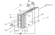
- the figure which shows the structure of the hydrocarbon production system Schematic diagram showing the configuration of the electrolytic reaction section
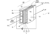
- Schematic diagram of an electrolytic cell unit including an electrolytic reaction section and a reverse water-gas shift reaction section Cross-sectional view of the electrolytic cell unit used in the comparative experiment in which the gas supply path on the electrode layer side was used as the reverse water-gas shift reaction part.
- Configuration diagram of a system equipped with a heat exchanger between the electrolytic reaction section and the reverse water-gas shift reaction section The figure which shows another structure of the hydrogen carbonization production system which guides CO 2 to a reverse water gas shift reaction part.
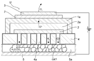
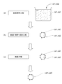
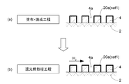
- Explanatory drawing showing the preparation state of a catalyst Explanatory drawing showing coating / firing state of catalyst and reduction pretreatment Schematic diagram of an electrolytic cell unit including an electrolytic reaction section, a reverse water-gas shift reaction section, and a hydrocarbon synthesis reaction section.
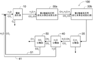
- the figure which shows another structure of a hydrocarbon production system The figure which shows the further another structure of the hydrocarbon production system.
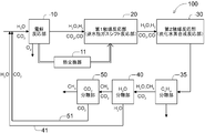
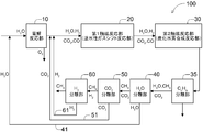
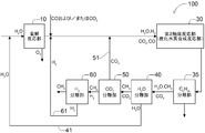
- FIG. 1 shows the configuration of one form of the hydrocarbon production system 100 proposed by the inventors.
- the hydrocarbon production system 100 includes an electrolytic reaction unit 10, a first catalytic reaction unit 20, a second catalytic reaction unit 30, a heavy hydrocarbon separation unit 35 (shown as a CnHm separation unit), and water. and a separating portion 40 (shown with CO 2 separation section) (H 2 shown as O separation section) and the carbon dioxide separation unit 50 is configured to include sequentially.
- the electrolytic reaction unit 10 is a portion that electrolyzes at least a part of the inflowing gas
- the first catalytic reaction unit 20 is a reverse water-gas shift reaction unit that undergoes a reverse water-gas shift reaction of at least a part of the inflowing gas.
- the second catalytic reaction unit 30 is configured to act as a hydrocarbon synthesis reaction unit that synthesizes at least a part of the inflowing gas into hydrogen.
- the hydrocarbon synthesized is mainly CH 4 (hydrocarbon having 1 carbon atom), but also includes lower saturated hydrocarbons having 2 to 4 carbon atoms and the like.
- hydrocarbons are a concept including all of them, and are also collectively referred to as hydrocarbons.
- Heavy hydrocarbon separation unit 35, water separator 40 and the carbon dioxide separation unit 50 predetermined components from a gas flowing within at the site to remove at least a portion of the be.
- the components removed and recovered by the water separation unit 40 and the carbon dioxide separation unit 50 are returned to a predetermined part of the system via the water return path 41 and the carbon dioxide return path 51 and are regenerated. It will be used. It is shown by H 2 O and CO 2 returned via the two return paths 41 and 51, respectively.
- These double return paths 41 and 51 serve as branch paths in the respective portions 40 and 50.
- the hydrocarbon production system 100 is established as a carbon closed system that does not substantially release CO 2 to the outside of the system.
- H 2 O and CO 2 as starting materials flow in and are electrolyzed internally, and H 2 O is decomposed into H 2 and O 2 and a part of CO. 2 is decomposed into CO and O 2 and released.
- the reaction is described as the following equilibrium reaction, but the reverse water-gas shift reaction is a reaction in which the reaction described by the following formula 3 proceeds to the right (CO 2 and H 2 react to generate CO and H 2 O). It becomes a reaction that goes in the direction of CO 2 + H 2 ⁇ CO + H 2 O (Equation 3)
- This formula 3 is also shown in the box showing the first catalytic reaction unit 20 (reverse water gas shift reaction unit) in FIG.
- the reverse water-gas shift catalyst cat1 used in the reaction is also schematically shown in this box.
- the reaction in which CH 4 is synthesized from CO and H 2 is described as the following equilibrium reaction, but the reaction in which CH 4 is synthesized from CO and H 2 is the reaction described in the following formula 4 on the right side.
- a reaction in which CO and H 2 react to form CH 4 and H 2 O CO + 3H 2 ⁇ CH 4 + H 2 O (Equation 4)
- This formula 4 is also shown in the box showing the second catalytic reaction section 30 (hydrocarbon synthesis reaction section) in FIG.
- the hydrocarbon synthesis catalyst cat2 used in the reaction is also schematically shown in this box.
- the inventors have shown an example of a catalyst using ruthenium as the catalytically active component of the hydrocarbon synthesis catalyst cat2 arranged in the second catalytic reaction unit 30, but iron as the catalytically active component thereof.
- Heavy hydrocarbons are also synthesized in catalysts containing or cobalt, and this type of heavy hydrocarbon can be condensed and separated from the transport gas as the temperature decreases. Therefore, the above-mentioned heavy hydrocarbon separation unit 35 separates the hydrocarbon component thus separated.
- the H 2 O generated in the water separation unit 40 is separated and returned to the upstream side of the electrolytic reaction unit 10 via the water return path 41 (water recycling line).
- the CO 2 generated in the carbon dioxide separation unit 50 is separated and returned to the upstream side of the electrolytic reaction unit 10 via the carbon dioxide return path 51 (carbon dioxide recycling line).
- the electrolytic reaction unit 10 decomposes H 2 O and CO 2 that flow in by consuming the electric power supplied according to the above formulas 1 and 2.
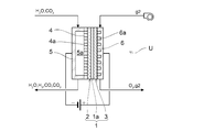
- FIG. 2 schematically shows the cross-sectional structure of the electrolytic reaction unit 10.
- the figure shows an electrolytic cell unit U which is laminated to form an electrolytic stack (not shown).
- the electrolytic cell unit U includes an electrolytic cell 1, and the electrolytic cell 1 is one of the electrolyte layers 1a.
- the electrode layer 2 is provided on the surface of the surface, and the counter electrode layer 3 is provided on the other surface.
- the electrode layer 2 serves as a cathode in the electrolytic cell 1, and the counter electrode layer 3 serves as an anode.
- this electrolytic cell unit U is supported by the metal support 4.
- a case where a solid oxide type electrolytic cell is used as the electrolytic cell 1 is illustrated.
- the electrolyte layer 1a can be formed in the state of a thin film having a thickness of 10 ⁇ m or less.
- the constituent materials include YSZ (yttria-stabilized zirconia), SSZ (scandia-stabilized zirconia), GDC (gadolinium-doped ceria), YDC (yttrium-doped ceria), SDC (samarium-doped ceria), and LSGM. (Strontium / magnesium-added lanthanum gallate) or the like can be used.
- zirconia-based ceramics are preferably used.
- the electrolyte layer 1a is provided by a low temperature firing method (for example, a wet method using a firing treatment in a low temperature range that does not perform a firing treatment in a high temperature range exceeding 1100 ° C.) or a spray coating method (spraying method, aerosol deposition method, aerosol gas deposition). It is preferably formed by a deposition method, a powder jet deposit method, a particle jet deposition method, a cold spray method, or the like), a PVD method (a sputtering method, a pulse laser deposition method, or the like), a CVD method, or the like.
- These film formation processes that can be used in a low temperature range provide an electrolyte layer 1a that is dense and has high airtightness and gas barrier properties without using firing in a high temperature range exceeding 1100 ° C., for example. Therefore, damage to the metal support 4 can be suppressed, element mutual diffusion between the metal support 4 and the electrode layer 2 can be suppressed, and an electrolytic cell unit U having excellent performance and durability can be realized.
- a low-temperature firing method, a spray coating method, or the like because a low-cost element can be realized.
- it is more preferable to use the spray coating method because the electrolyte layer 1a, which is dense and has high airtightness and gas barrier property, can be easily obtained in a low temperature range.
- the electrolyte layer 1a is densely configured in order to shield gas leaks and exhibit high ionic conductivity.
- the density of the electrolyte layer 1a is preferably 90% or more, more preferably 95% or more, and further preferably 98% or more.
- the electrolyte layer 1a is a uniform layer, its density is preferably 95% or more, and more preferably 98% or more.
- the electrolyte layer 1a is composed of a plurality of layers, it is preferable that at least a part of the electrolyte layer 1a contains a layer having a density of 98% or more (dense electrolyte layer), which is 99%. It is more preferable to include the above-mentioned layer (dense electrolyte layer).
- the electrolyte layer 1a When such a dense electrolyte layer is contained in a part of the electrolyte layer 1a, even when the electrolyte layer 1a is formed in a plurality of layers, the electrolyte layer 1a is dense and has high airtightness and gas barrier property. This is because it can be easily formed.
- the electrode layer 2 can be provided in a thin layer on the front surface of the metal support 4 and in a region larger than the region where the holes 4a are provided.
- the thickness thereof can be, for example, about 1 ⁇ m to 100 ⁇ m, preferably 5 ⁇ m to 50 ⁇ m. With such a thickness, it is possible to secure sufficient electrode performance while reducing the amount of expensive electrode layer material used to reduce costs.
- the entire region provided with the holes (through holes) 4a is covered with the electrode layer 2. That is, the hole 4a is formed inside the region of the metal support 4 where the electrode layer 2 is formed. In other words, all the holes 4a are provided facing the electrode layer 2.
- the constituent material of the electrode layer 2 for example, a composite material such as NiO-GDC, Ni-GDC, NiO-YSZ, Ni-YSZ, CuO-CeO 2 , and Cu-CeO 2 can be used.
- GDC, YSZ, and CeO 2 can be referred to as composite aggregates.
- the electrode layer 2 is provided with a low temperature firing method (for example, a wet method using a firing treatment in a low temperature range that does not perform a firing treatment in a high temperature range higher than 1100 ° C.) or a spray coating method (spraying method, aerosol deposition method, aerosol gas).
- It is preferably formed by a deposit method, a powder jet deposit method, a particle jet deposit method, a cold spray method, or the like), a PVD method (a sputtering method, a pulse laser deposit method, or the like), a CVD method, or the like.
- a deposit method a powder jet deposit method, a particle jet deposit method, a cold spray method, or the like
- PVD method a sputtering method, a pulse laser deposit method, or the like
- CVD method or the like.
- the counter electrode layer 3 can be formed in a thin layer on the surface of the electrolyte layer 1a opposite to the electrode layer 2.
- the thickness thereof can be, for example, about 1 ⁇ m to 100 ⁇ m, preferably 5 ⁇ m to 50 ⁇ m. With such a thickness, it is possible to secure sufficient electrode performance while reducing the amount of expensive counter electrode layer material used to reduce costs.
- a composite oxide such as LSCF or LSM, a ceria oxide, or a mixture thereof can be used.
- the counter electrode layer 3 contains a perovskite-type oxide containing two or more kinds of elements selected from the group consisting of La, Sr, Sm, Mn, Co and Fe.
- the electrolyte layer 1a, the electrode layer 2 and the counter electrode layer 3 are formed as a thin film as described later, and the inventor calls this a thin layer formation.
- the electrolytic cell unit U has a metal support type, includes a metal support 4 as a support for the electrode layer 2, and U on the side opposite to the electrode layer 2 sandwiching the metal support 4.
- a supply path forming member 5 for forming the character-shaped electrode layer side gas supply path 5a is provided.
- the metal support 4 is provided with a large number of holes 4a so as to penetrate the front and back surfaces.
- Gas supplied through the electrode layer side gas supply passage 5a (H 2 O and CO 2) are subject to electrolysis, is supplied to the electrode layer 2 through a number of holes 4a. Furthermore, gas produced (H 2, CO) is the outflow from the hole 4a.
- a supply path forming member 6 for forming the gas supply path 6a on the counter electrode layer side is provided.
- the supply path forming member 6 is provided with many grooves on the counter electrode layer 3 side, and supplies gas g2 (for example, air or the like) for transportation to the counter electrode layer side gas supply path 6a. It is configured.
- the metal support 4 plays a role as a support that supports the electrode layer 2, the electrolyte layer 1a, and the counter electrode layer 3 and maintains the strength of the electrolytic cell 1 and the electrolytic cell unit U as a whole.
- the plate-shaped metal support 4 is used as the metal support, but other shapes such as a box shape and a cylindrical shape are also possible.
- the metal support 4 may have sufficient strength to form the electrolytic cell unit U as a support, for example, about 0.1 mm to 2 mm, preferably about 0.1 mm to 1 mm, more preferably about 0.1 mm to 1 mm. Those having a thickness of about 0.1 mm to 0.5 mm can be used.
- the support is made of metal, but ceramics can also be used, for example.
- the metal support 4 has, for example, a plurality of holes 4a provided so as to penetrate the front surface and the back surface of the metal plate.
- the hole 4a can be provided in the metal support 4 by mechanical, chemical or optical drilling.
- the hole 4a has a function of allowing gas to permeate from the back surface to the front surface of the metal support 4.
- the holes 4a may be provided at an angle in the gas advection direction (the front and back directions of the paper surface in FIG. 2).
- a ferritic stainless steel material an example of an Fe—Cr alloy
- YSZ yttria-stabilized zirconia
- GDC yttria-stabilized zirconia
- GDC itria-stabilized zirconia
- the coefficient of thermal expansion can be made close to that of gadrinium-doped ceria, also called CGO). Therefore, the electrolytic cell unit U is less likely to be damaged even when the low temperature and high temperature cycles are repeated. Therefore, it is preferable because the electrolytic cell unit U having excellent long-term durability can be realized.
- the same material as that of the metal support 4 can be used for the supply path forming members 5 and 6 of the electrolytic cell unit U, and the thickness thereof can be substantially the same.
- the metal support 4 and both supply path forming members 5 and 6 have conductivity, but when they are airtightly configured, they function as separators for separating the supply paths 5a and 6a.
- the electrolytic cell unit U having the above configuration has DC power between a pair of electrode layers 2 and 3 provided with the electrolyte layer 1a sandwiched from the power supply unit (shown by a battery in FIG. 2). Supply.
- the electrode layer 2 side may be positive and the counter electrode layer 3 side may be negative.
- H 2 O and CO 2 which are gases to be electrolyzed, are supplied to the electrode layer 2 from the electrolytic raw material supply unit (upstream portion of the electrolytic reaction unit 10 in FIG. 1), and the transfer gas is supplied to the counter electrode layer side.
- the reactions represented by the formulas 1 and 2 can be caused in the electrolytic cell 1 and the decomposed gas can be taken out.
- H 2 O either water or steam may be used, or both of them may be used. Therefore, in the present invention, at least an electrolytic cell unit U, an electrolytic raw material supply unit that supplies water and / or steam and carbon dioxide to the electrolytic cell unit U, and a power supply unit that supplies electric power are provided.
- An electrolytic cell device is constructed.
- the gas supplied in the electrolytic reaction (H 2 O, CO 2 ) and the released gas (H 2 O, H 2 , CO, O 2 , CO 2 ) are shown above and below the electrolytic cell unit U in FIG.
- the above-mentioned electrode layer side gas supply path 5a and counter electrode layer side gas supply path 6a are formed so as to extend in the front and back directions of the paper surface of FIG. , for example, the supply side of the gas (H 2 O, CO 2) according to the upper side of the electrolytic cell unit U in FIG. 2 from paper front, release side of the gas (H 2 O according to the lower side of the electrolytic cell 1, H 2, CO, from O 2, CO 2) the paper back, it is possible to recover operation (see FIG. 4 to be described later).
- a transport gas g2 such as air can be flowed through the electrolytic cell unit U.
- the first catalytic reaction unit 20 (reverse water gas shift reaction unit) causes a reverse water gas shift reaction to convert CO 2 into CO using the supplied H 2 , and H 2 and H 2 O. That is, in the electrolytic reaction unit 10 that supplies H 2 O and CO 2 to electrolyze, the remaining CO 2 that is not decomposed is converted into CO.
- the reaction here is as shown in Equation 3, but this reaction is an endothermic reaction and is an equilibrium reaction according to the reaction temperature conditions.
- the catalyst is capable of causing the reaction represented by the formula 3 on the high temperature side (for example, 600 ° C. to 800 ° C.) as much as possible.
- a component having activity as a catalyst may be referred to as a "catalytically active component”
- a carrier carrying the catalytically active component may be referred to as a “carrier”.
- the inventors examined various combinations of catalytically active ingredients and carriers as described later, and found that a specific combination was suitable.
- a carrier metal oxide
- a carrier-supported catalyst impregnation-supporting step.
- This heat treatment is a firing treatment. The preparation and use of the catalyst will be described with reference to FIGS. 11 and 12.
- FIG. 11 shows examples of the reverse water-gas shift catalyst cat1 and the hydrocarbon synthesis catalyst cat2 according to the present invention.
- the catalytically active component of the reverse water-gas shift catalyst cat1 is referred to as ca1
- the carrier thereof is referred to as cb1.
- the hydrocarbon synthesis catalyst cat2 the catalytically active component thereof is ca2 and the carrier thereof is cb2.
- an aqueous solution of a compound containing a metal component (which is a metal catalyst) to be the catalytically active components ca1 and ca2 is obtained, and the carriers cb1 and cb2 are added to the aqueous solution and stirred.
- the impregnation-supporting step (a) for impregnation evaporative drying, drying, and then drying / crushing / molding step (b) for pulverization and molding are performed, and the obtained molded product is placed in the air.
- the firing step (c) for firing the target products (cat1 and cat2) can be obtained. Therefore, this form of catalyst is also referred to as an impregnation-supported catalyst.
- FIG. 12A shows a coating / firing step in which the reverse water gas shift catalyst cat1 is applied to the metal support 4 in which the holes 4a are perforated to form a coating layer 20a, and the coating layer 20a is fired.
- FIG. 12B shows a reduction pretreatment step in which H2 is flowed to perform reduction pretreatment before using the reverse water gas shift catalyst cat1.
- FIG. 1 When the firing treatment is performed in air, some or all of the supported catalytically active components ca1 and ca2 are in a state of being oxidized.
- a so-called reduction pretreatment may be performed to reduce the catalytically active component in an oxidized state to sufficiently enhance its activity.
- Figure A 12 (b), (typically H 2) on the surface of the catalyst reducing gas showing a state in which performing reduction pretreatment allowed to flow.
- Catalyst used As the reverse water-gas shift catalyst cat1 used for the first catalyst reaction unit 20, the inventors have selected a catalyst that satisfies the following requirements.
- the ratio of the carrier cb1 to the entire catalyst is preferably 55% by weight or more, more preferably 60% by weight or more, and further preferably 65% by weight or more. preferable. Further, the upper limit of this ratio can be, for example, 99.5% by weight, but if it is more than this, the catalytically active component ca1 cannot be sufficiently supported, and it may be difficult to obtain the effect as the reverse water gas shift catalyst cat1. Is.
- ceria-based metal oxide ceria doped with at least one of gadolinium, samarium, and yttrium can also be used.
- zirconia-based metal oxide zirconia stabilized with at least one of yttria and scandia can also be used.
- the amount of the catalytically active component ca1 supported is preferably 0.5% by weight or more, more preferably 1% by weight or more, and 5% by weight or more. Is more preferable. Further, even if the amount of the catalytically active component ca1 supported is increased too much, it becomes difficult to support the catalytically active component ca1 with high dispersion, it is difficult to obtain a significant improvement in catalytic activity, and the cost of the catalyst increases.
- the amount of the catalytically active component ca1 supported is preferably 35% by weight or less, more preferably 30% by weight or less, and further preferably 25% by weight or less.
- the catalytically active component ca1 it is also preferable to add either one or both of nickel and iron to the catalytically active component ca1 to support copper as a further catalytically active component ca1.
- the amount of copper supported is equal to or less than the amount supported by the catalytically active component ca1 in either or both of nickel and iron as the main catalytically active component ca1.
- the test results of Examples in the case where the catalytically active component ca1 and the carrier cb1 are variously changed as the reverse water-gas shift catalyst cat1 used in the first catalytic reaction unit 20 will be described.
- the catalytically active component ca1 Ni and Fe were examined and compared with Pt (platinum).
- the carrier cb1 Al 2 O 3 (alumina) was also examined using ZrO 2 (zirconia), YSZ (yttria-stabilized zirconia), GDC (gadrinium-doped ceria), and CeO 2 (ceria) as examples.
- Test Example 1 and Test Example 2 will be introduced, but the difference between the two tests is that in the firing of the reverse water-gas shift catalyst cat1, Test Example 1 has a firing temperature of 450 ° C., and Test Example 2 has its firing. The point is that the temperature is set to 600 ° C. to 1000 ° C. on the high temperature side.
- Test Example 1 The test results of Examples (1 to 19) when the carrier is variously changed as the catalyst used in the first catalytic reaction unit 20 will be described.
- Catalytically active components Ni and Fe were examined, and Pt (platinum) was also examined.
- As the carrier ZrO 2 (zirconia), YSZ (yttria-stabilized zirconia), GDC (gadrinium-doped ceria), and CeO 2 (ceria) were used as examples, and Al 2 O 3 (alumina) was also examined.
- a water-soluble copper compound (copper nitrate, copper chloride, copper sulfate, ammonium copper sulfate, copper acetate, copper oxalate, copper citrate, etc.) is similarly used. Quantify to obtain a dissolved aqueous solution. A predetermined amount of carrier powder (ceria, zirconia, GDC, YSZ, Al 2 O 3 ) is added to the aqueous solution, stirred and impregnated, then evaporated to dryness, dried, then crushed and molded, and then fired in air. do.
- carrier powder ceria, zirconia, GDC, YSZ, Al 2 O 3
- the catalysts of the following examples were prepared using nickel nitrate hexahydrate, iron nitrate nine hydrate, and copper nitrate trihydrate, respectively.
- the catalyst using Pt was prepared using tetraammine platinum hydroxide.
- the temperatures of evaporation to dryness, drying, and firing can be carried out in a generally used temperature range, but in Test Example 1, the catalysts of the following examples are each at 80 ° C. , 80 ° C and 450 ° C.
- Table 1 shows Examples 1 to 19 of the reverse water-gas shift catalyst cat1 in the present invention.
- the horizontal axis represents the type of carrier cb1, the amount of metal supported as a catalytically active component (% by weight; expressed as wt.% In the table), the amount of CO adsorbed (ml / g), and the BET surface area (m 2 / g). There is.
- the CO adsorption amount the CO adsorption amount was measured after the catalyst was subjected to reduction pretreatment at 350 ° C. for 1 hour in a hydrogen atmosphere.
- Catalytic activity test The catalyst activity test, a mixed gas of 50% H 2 -50% CO 2 (H 2 and CO 2 is 1: 1 (mixture gas contained in a volume ratio)) was used as a reaction gas, GHSV (Gas Hourly Space Velocity) The reaction temperature was changed from 600 ° C. to 800 ° C. in increments of 50 ° C. under the condition of 10000 / h. Before conducting the catalytic activity test, the catalyst was pretreated for reduction at 600 ° C. while flowing hydrogen gas through the catalyst layer. As a test result, the CO concentration (%) and the CH4 concentration (%) at the outlet of the reaction part are shown in Table 2 together with the CO 2 conversion rate (%).
- the CO 2 conversion rate (%) was calculated according to the following formula based on the gas analysis result at the outlet of the catalyst layer. [CH 4 concentration] + [CO concentration] / ([CH 4 concentration] + [CO concentration] + [CO 2 concentration])
- the reverse water gas shift catalyst cat1 used in the first catalyst reaction unit 20 has a CO 2 conversion rate (%) on the high temperature side (for example, around 600 to 800 ° C.). ) Is desirable.
- Test Example 2 Hereinafter, the test results of Example (20-29) of Test Example 2 will be described. Even in this example Ni and Fe were examined as catalytically active components, and the addition of Cu was also examined.
- As the carrier CeO 2 (ceria) and ZrO 2 (zirconia) are used as examples, and Al 2 O 3 (alumina) is also being investigated.
- the reverse water-gas shift catalyst cat1 used in Test Example 2 was prepared in the same manner as in Test Example 1 except that the firing temperatures were changed to 600 ° C., 800 ° C., and 1000 ° C.
- Table 3 shows each catalyst of Examples (20 to 29) prepared.
- Catalytic activity test In the catalytic activity test, a mixed gas containing H 2 and CO 2 in a ratio of 1: 1 (volume ratio) was used as the reaction gas, and the reaction temperature was set in increments of 50 ° C. from 600 ° C. to 800 ° C. under the condition of GHSV of 10000 / h. I went while changing with. Before conducting the catalytic activity test, the catalyst was pretreated for reduction at 600 ° C. while flowing hydrogen gas through the catalyst layer. As a test result, the CO concentration (%) and the CH 4 concentration (%) at the outlet of the reaction part are shown in Table 4 together with the CO 2 conversion rate (%).
- Iron / Zirconia Catalyst and Iron / Alumina Catalyst The test results of the iron / zirconia catalyst at firing temperatures of 450 ° C, 600 ° C, 800 ° C, and 1000 ° C are shown in Example 8, Example 22, and Example 26, respectively. It is shown in Example 29. On the other hand, for the iron / alumina catalyst, the test results when the firing temperatures are 450 ° C., 600 ° C., and 800 ° C. are shown in Example 14, Example 23, and Example 27, respectively. As can be seen from these results, although the amount of metal supported is slightly different, the iron / zirconia catalyst is superior to the iron / alumina catalyst in performing the reverse water-gas shift reaction.
- the iron / zirconia catalyst has extremely high catalytic activity not only when the firing temperature is 450 ° C. but also when the firing temperature is as high as 600 ° C., 800 ° C., 1000 ° C., and any firing temperature is used. Even when set to, the CO 2 conversion rate reaches the vicinity of the equilibrium value.
- Example 4 The test results when the nickel / ceria catalyst firing temperature is 450 ° C., 600 ° C., 800 ° C., and 1000 ° C. are shown in Example 4, Example 20, Example 24, and Example 28, respectively.
- the nickel-ceria catalyst has extremely high catalytic activity not only when the firing temperature is 450 ° C. but also when the firing temperature is as high as 600 ° C., 800 ° C., or 1000 ° C. At any firing temperature, the CO 2 conversion rate reaches near the equilibrium value.
- Example 7 shows the test results when the nickel-alumina catalyst firing temperature was 450 ° C. As a result, the CO 2 conversion rate of the nickel-alumina catalyst was lower than that of the nickel-ceria catalyst described above.
- Example 6 The test results when the nickel / copper / ceria catalyst firing temperatures are 450 ° C., 600 ° C., and 800 ° C. are shown in Example 6, Example 21, and Example 25, respectively. From these results, it can be seen that the CO 2 conversion rate of nickel / copper / ceria catalysts tends to decrease slightly when the firing temperature is as high as 600 ° C or 800 ° C, but the firing temperature conditions described above are the same. Superior to iron / alumina catalysts. Further, in the nickel / copper / ceria catalyst having a firing temperature of 450 ° C., the CO 2 conversion rate reaches the vicinity of the equilibrium value.
- iron-zirconia-based catalysts and nickel-ceria-based catalysts have extremely high reverse water-based catalysts even if the firing temperature is changed to 450 ° C to 1000 ° C. Since it exhibits gas shift catalytic activity, it is useful because it facilitates ensuring high performance and durability even when used in combination with a solid oxide fuel cell used in a high temperature range of, for example, around 600 ° C to 800 ° C.
- the carrier cb1 containing a ceria-based metal oxide or a zirconia-based metal oxide as a main component was used as the reverse aqueous gas shift catalyst cat1 used in the first catalytic reaction unit 20.
- a catalyst composed by supporting at least one or both of nickel and iron as the catalytically active component ca1 can be used as the reverse aqueous gas shift catalyst cat1 used in the first catalytic reaction unit 20.
- ceria-based metal oxide as the carrier cb1, ceria doped with at least one of gadolinium, samarium, and yttrium can be used.
- zirconia-based metal oxide as the carrier cb1 can be zirconia stabilized with at least one of yttria and scandia.
- reverse water-gas shift catalyst cat1 in the first catalyst reaction unit 20 (reverse water-gas shift reaction unit), it is equivalent to the Pt catalyst, which has high activity but is very expensive at around 600 to 1000 ° C.
- the reverse water-gas shift reaction can be carried out at the above CO2 conversion rate (%). Since the test of this example was performed under a very high GHSV condition of 10000 / h, the GHSV was made smaller than 10000 / h, that is, the amount of catalyst used for the amount of gas to be treated. It is also possible to carry out a reverse water-gas shift reaction with a higher CO 2 conversion rate (%).
- FIG. 3 shows a configuration in which these two reaction units 10 and 20 are combined and integrated, and that they are integrated is shown by enclosing both parts.
- the reaction when integrated in the same box in this way was shown.
- the above-mentioned equations 1, 2 and 3 are performed.
- the electrolytic reaction unit 10 and the reverse water gas shift reaction unit 20 are combined and integrated, if they are surrounded together by a heat insulating member, heat is transferred between the electrolytic reaction unit 10 and the reverse water gas shift reaction unit 20. Is preferable because it can be performed efficiently. Further, in order to transfer the heat generated in the electrolytic reaction unit 10 to the reverse water gas shift reaction unit 20, the electrolytic reaction unit 10 and the reverse water gas shift reaction unit 20 may be connected by using a heat transfer member.
- the reverse water-gas shift reaction unit 20 in the electrolytic cell unit U which is the electrolytic reaction unit 10. This is because when a solid oxide fuel cell that operates at around 600 to 800 ° C. is used as the electrolytic cell 1, the electrolytic reaction unit 10 is used in the reverse water-gas shift catalyst cat1 of the present application, which can obtain high activity at around 600 to 800 ° C. This is because the reverse water-gas shift reaction unit 20 can be used in the same temperature range. In this case as well, it is sufficient that the gas that has passed through the electrolytic reaction unit 10 is guided to the reverse water-gas shift reaction unit 20 to generate a reverse water-gas shift reaction.
- FIG. 4 shows an electrolytic cell unit U provided with such a reverse water-gas shift reaction unit 20.
- FIG. 4 is a view of the electrolytic cell unit U shown in cross section in FIG. 2 including the advection direction of the gas.
- the cross section of the electrolytic cell unit U is basically the same. That is, this electrolytic cell unit U also has an electrolytic cell 1 in which an electrode layer 2 and a counter electrode layer 3 are formed with the electrolyte layer 1a sandwiched therein, a metal support 4 that functions as a support thereof, and a metal support 4 that functions as a separator. It is configured to include path forming members 5 and 6, and is configured to form an electrode layer side gas supply path 5a and a counter electrode layer side gas supply path 6a. More specifically, as can be seen from the figure, when the metal support 4 is viewed in the gas advection direction, the hole 4a is provided in the portion corresponding to the electrolytic cell 1, but it is downstream from the electrode layer 2. Is not provided with holes. Therefore, the metal support 4 is supplied to the electrode layer 2 and released from the electrode layer 2, and is supplied to the counter electrode layer 3 gas and is discharged from the counter electrode layer 3. Is a separator that effectively separates.
- the inner surface of the electrode layer side gas supply path 5a (the inner surface of the supply path forming member 5 on the supply path side, the surface of the metal support 4 opposite to the surface on which the electrode layer 2 is formed, and the plurality of holes 4a).
- the reverse water-gas shift catalyst cat1 described above is applied to the surface of the surface).
- the coating layer 20a is shown by a thick solid line. Further, the electrode layer side gas supply path 5a extends beyond the electrolytic reaction section 10, and the coating layer 20a is also provided on the extension side.
- the electrode layer side gas supply path 5a of the electrolytic cell unit U is a discharge path for discharging at least H 2 generated in the electrode layer 2, and the electrolytic reaction unit 10 and the reverse water gas shift reaction unit 20 are integrated.
- the configuration is provided for the electrolytic cell unit U.
- the sex gas shift reaction unit 20 By stacking the electrolytic cell units U configured in this manner in the left-right directions of FIGS. 2 and 4, a large number of electrolytic cell units U are laminated, and the so-called electrolytic cell modules (the so-called electrolytic cell modules) to which they are electrically connected are laminated. (Not shown) can be formed. Of course, the useful gas produced can be obtained over multiple layers.
- FIG. 5 shows a cross section of the electrolytic cell unit U used in this experiment.
- FIG. 1 shows a cross-sectional view of the electrolytic cell unit U.
- the electrolytic cell 1 a metal-supported solid oxide-type electrolytic cell was used.
- the metal support 4 a metal substrate was produced by providing a plurality of through holes (which become holes 4a) by laser processing on a metal plate of ferritic stainless steel having a thickness of 0.3 mm.
- the electrode layer 2 and the intermediate layer 2a were laminated in this order on the metal substrate, and the electrolyte layer 1a was laminated on the intermediate layer 2a of the metal substrate so as to cover the intermediate layer 2a.
- reaction prevention layer 7 and the counter electrode layer 3 were laminated in this order on the electrolyte layer 1a to prepare an electrolytic cell 1.
- a mixture of NiO powder and GDC powder is used as the material for forming the electrode layer 2
- GDC powder is used as the material for forming the intermediate layer 2a
- 8YSZ (8 mol% yttria stable) is used as the material for forming the electrolyte layer 1a.
- the zirconia powder was used
- GDC powder was used as the material for forming the reaction prevention layer 7
- a mixture of GDC powder and LSCF powder was used as the material for forming the counter electrode layer 3.
- the thicknesses of the electrode layer 2, the intermediate layer 2a, the electrolyte layer 1a, the reaction prevention layer 7, and the counter electrode layer 3 are about 25 ⁇ m, about 10 ⁇ m, about 5 ⁇ m, about 5 ⁇ m, and about 20 ⁇ m, respectively. rice field.
- the intermediate layer 2a and the reaction prevention layer 7 are formed by a low temperature firing method (for example, a wet method using a firing treatment in a low temperature range in which the firing treatment is not performed in a high temperature range higher than 1100 ° C.) or a spray coating method (spraying method or aerosol de).
- a low temperature firing method for example, a wet method using a firing treatment in a low temperature range in which the firing treatment is not performed in a high temperature range higher than 1100 ° C.
- a spray coating method spray coating method or aerosol de
- These processes that can be used in the low temperature region provide a good intermediate layer 2a and reaction prevention layer 7 without using firing in a high temperature region higher than, for example, 1100 ° C. Therefore, it is prefer
- the electrolytic cell 1 is formed in a thin layer on the metal support 4, and the reverse water-gas shift reaction unit 20 that generates CO by using CO 2 and the H 2 by the reverse water-gas shift reaction is electrolyzed.
- the composition ratio of CO to H 2 generated by electrolysis could be increased.
- the carbon monoxide ([H 2 / CO]) ratio changes from about 10 or more to about 5, and by combining the reaction of the electrolytic reaction unit 10 and the reaction of the reverse water-gas shift reaction unit 20, CO that is advantageous for various hydrocarbon synthesis. It is preferable because the amount of hydrogen can be secured.
- the reaction of the electrolytic reaction unit 10 and the reverse water gas shift reaction unit 20 It is preferable to combine the reactions because the amount of CO can be secured. This one mole of CO 2 while the 2 moles of H 2 O is produced when the methanation, one mole of CO 2 from the need in the generation of one mole of H 2 O If the methanation Trip hydrocarbon production system 100 employing the methanation reaction of CO is, is because it prevented the loss amount of 1 mole of H 2 O content of the latent and sensible heat in the entire system.
- the inventors have called the system including the electrolytic reaction unit 10 and the reverse water-gas shift reaction unit 20 described so far as an “electrolytic reaction system”.
- evaluation tests 1 to 4 are tests for whether or not a gas having a desired number of calories or more (referred to as a high-calorie gas) can be obtained as the gas to be produced, and the evaluation test 5 is a heavy hydrocarbon obtained at the same time during the production. This is a confirmation test for hydrogen.
- a catalyst was prepared by variously changing the carrier and the catalytically active component.
- the catalytically active component ca2 those obtained by adding Mo, V, Fe, Co and the like to Ru and Ru, and Ni were examined.
- the carrier cb2 ZrO 2 , Al 2 O 3 , SiO 2 , MgO, and TiO 2 were examined.
- the preparation of the hydrocarbon synthesis catalyst cat2 is also the method adopted as described in FIGS. 11 and 12. That is, an aqueous solution obtained by quantifying and dissolving a water-soluble ruthenium compound (ruthenium nitrate, ruthenium chloride, ruthenium sulfate, ruthenium ammonium sulfate, ruthenium acetate, ruthenium oxalate, ruthenium citrate, etc.) according to the composition of the target catalyst is obtained. Further, when molybdenum, vanadium, iron, and cobalt are supported as further catalytically active components, these water-soluble metal compounds are similarly quantified to obtain a dissolved aqueous solution.
- ruthenium nitrate, ruthenium chloride, ruthenium sulfate, ruthenium ammonium sulfate, ruthenium acetate, ruthenium oxalate, ruthenium citrate, etc. ruthenium
- a predetermined amount of carrier particles ZrO 2 , Al 2 O 3 , SiO 2 , MgO, TiO 2 ) are added to the aqueous solution, impregnated and supported with a catalytically active component, and dried or fired.
- the hydrocarbon synthesis catalyst cat2 can be obtained by performing a necessary treatment step such as a reduction treatment.
- an aqueous solution of ruthenium chloride, an aqueous solution of ammonium molybdate, an aqueous solution of vanadyl oxalate, an aqueous solution of iron nitrate, and an aqueous solution of cobalt nitrate are used, respectively. It was prepared using a sequential carrier method (a two-step carrier method in which a catalytically active ingredient other than ruthenium is first supported on a carrier and then ruthenium is supported). Evaluation test 5 is described separately.
- evaluation test 1 In the evaluation test 1, the CO 12.4%, the CO 2 24.8%, the H 2 37.2%, comprising 12.4% of H 2 O, the reaction gas a mixed gas of balance was N 2
- the activity of the hydrocarbon synthesis catalyst cat2 was tested at a reaction temperature between 275 ° C. and 360 ° C. at a GHSV of 4000 / h (WET base).
- the reaction gas is co-electrolytic reaction of water and carbon dioxide in the electrolytic reaction unit 10 under the condition that the electrolytic reaction rate of carbon dioxide is low, and carbon dioxide is produced in the reverse water-gas shift reaction unit 20 installed in the subsequent stage.
- An example assuming a model in which a mixed gas of CO, CO 2 , H 2 , and H 2 O after the reverse water-gas shift reaction of carbon is introduced into the hydrocarbon synthesis reaction unit 30 to carry out the hydrocarbon synthesis reaction. Is.
- Tables 7 and 8 shown below show Examples B1 to B3 of the hydrocarbon synthesis catalyst cat2 in the present invention.
- evaluation test 2 In evaluation test 2, the CO 0.45%, the CO 2 18.0%, the H 2 71.55%, the mixed gas used for the reaction gas containing 10.0% of H 2 O, the GHSV 5000 / The activity of the hydrocarbon synthesis catalyst cat2 was tested at a reaction temperature between about 230 ° C. and about 330 ° C. using h (DRY base).
- the reaction gas As the reaction gas in this case, the mixed gas obtained when the co-electrolysis reaction of water and carbon dioxide is carried out in the electrolytic reaction unit 10 under the condition that the electrolytic reaction rate of carbon dioxide is low is used in the hydrocarbon synthesis reaction unit 30. This is an example assuming a model in which a hydrocarbon synthesis reaction is carried out by introducing the gas.
- Hydrocarbon conversion rate [Number of carbons in hydrocarbons in outlet gas] / [Number of carbons in outlet gas] This index is an index indicating the ratio of the number of carbon atoms converted into hydrocarbons without being converted into CO 2 among the total carbons flowing in, and it is preferable that this index is high.
- the activity test of the hydrocarbon synthesis catalyst cat2 was carried out at the reaction temperature between them. In this activity test, a catalyst (Examples B17 and B18) in which iron or cobalt was supported in addition to ruthenium was used as a titania carrier.
- the reaction gas in this case is a mixed gas obtained by adding carbon monoxide to hydrogen obtained by electrolyzing water in the electrolytic reaction unit 10, or a gas obtained by performing a co-electrolysis reaction of water and carbon dioxide.
- a mixed gas of hydrogen and carbon monoxide obtained by separating water and carbon dioxide as needed was introduced into the hydrocarbon synthesis reaction unit 30 to carry out the hydrocarbon synthesis reaction. This is an example.
- Table 11 shows the results of evaluation test 3.
- hydrocarbons can be synthesized from a mixed gas containing H 2 and CO by using a catalyst in which ruthenium and iron or cobalt are supported on a titania carrier as a hydrocarbon synthesis catalyst cat2. rice field.
- the above-mentioned hydrocarbon production system 100 can generate a high-calorie gas having a C1-C4 calorific value of 39 MJ / Nm 3 or more.
- Evaluation test 4 In the evaluation test 4, a mixed gas containing 0.5% CO, 20.0% CO2, and 79.5% H2 was used as the reaction gas, and the GHSV was 5000 / h (DRY base), and the temperature was about 260 ° C. to The activity test of the hydrocarbon synthesis catalyst cat2 was carried out at a reaction temperature between about 290 ° C.
- the reaction gas in this case corresponds to a mixed gas obtained by separating and removing water from the reaction gas used in the evaluation test 2.
- Table 12 shows the test results for evaluation test 4.
- the hydrocarbon synthesis reaction unit 30 is capable of separating water in the first stage of the second catalytic reaction unit 30 (hydrocarbon synthesis reaction unit). It was found that the hydrocarbon conversion rate can be improved even at a lower reaction temperature, and the activity of the catalyst can be improved. Therefore, the configuration of the hydrocarbon production system 100 shown in FIG. 9, which will be described later in another embodiment, is also effective.
- the specific preparation method is as follows.
- a titania carrier as a metal oxide carrier was impregnated with an iron-containing aqueous solution having a predetermined concentration, and iron was supported on the titania carrier.
- This iron-supported titania was impregnated with an aqueous solution of ruthenium chloride having a predetermined concentration.
- a wet reduction treatment was carried out using an aqueous hydrazine solution to obtain iron-ruthenium-supported titania as a hydrocarbon synthesis catalyst cat2.
- the amount of iron and ruthenium supported on the hydrocarbon synthesis catalyst cat2 can be arbitrarily set depending on the concentration of each aqueous solution and the impregnation conditions.
- a spherical titania having a diameter of 2 to 4 mm is used as the hydrocarbon synthesis catalyst cat2 in the evaluation test 5.
- iron-ruthenium-supported titania (2 wt.% Ru / 2 wt.% Fe / TiO 2 ) having an iron content (supported amount) of 2% by weight and a ruthenium content (supported amount) of 2% by weight). And said.
- the reduction pretreatment shown in FIG. 12 (b) was performed. Specifically, while flowing nitrogen gas containing 10% hydrogen as hydrogen-containing gas through the catalyst storage section which becomes the hydrocarbon synthesis reaction section 30, the temperature of the catalyst section is maintained at 350 ° C. for 1 hour before the use of the catalyst. Hydrogen treatment (reduction pretreatment) was performed.
- the hydrogen-containing gas used in the reduction pretreatment can be reduced in hydrogen consumption by using a mixed gas of hydrogen and nitrogen in this way. Therefore, in this reduction pretreatment, for example, it is preferable to use a mixed gas of hydrogen and nitrogen having a hydrogen concentration of 20% by volume or less, and in the present embodiment, hydrogen containing 10% by volume of hydrogen and the remainder being nitrogen gas. It was decided to perform the reduction pretreatment of the hydrocarbon synthesis catalyst cat2 using the contained gas.
- Heavy Hydrocarbon Confirmation Test 1 A hydrocarbon synthesis test was carried out at a reaction temperature of 275 ° C. for about 80 hours using the hydrocarbon synthesis catalyst cat2 (2 wt.% Ru / 2 wt.% Fe / TiO 2) subjected to the above reduction pretreatment. As a result, a gas using a gas chromatograph shows that methane (CH 4 ) is the main component and C2-C6 hydrocarbons such as ethane, propane, and butane are continuously produced at the outlet of the catalytic reaction section. Confirmed by analysis.
- Evaluation test 5 confirmed that when the hydrocarbon synthesis catalyst cat2 according to the present invention was used, lower saturated hydrocarbons could be produced and heavy hydrocarbons could also be produced.
- a catalyst in which at least ruthenium is supported as the catalytically active component ca2 on the metal oxide carrier cb2 can be used in the second catalytic reaction section 30 (hydrocarbon synthesis reaction section). Further, it is preferable to support at least one of molybdenum, vanadium, iron and cobalt as the catalytically active component ca2.
- the hydrocarbon synthesis catalyst cat2 is preferably a catalyst in which at least ruthenium is supported on the metal oxide carrier cb2, and the amount of ruthenium supported is preferably 0.1% by weight or more and 5% by weight or less, and the metal oxidation. It was found that it is preferable to support at least one of molybdenum, vanadium, iron, and cobalt as the catalytically active component ca2 on the product carrier cb2 in addition to ruthenium.
- the amount of at least one of the molybdenum, vanadium, iron, and cobalt supported can be 0.2% by weight or more and 6% by weight or less.
- the amount of carbon monoxide adsorbed by the highly active catalyst was 0.4 ml / g or more.
- the water separating unit 40 is arranged condenser, a gas containing H 2 O to be flowed adjusted to a predetermined temperature and pressure, taking the water externally condensed.
- this portion 50 is arranged PSA, with the separation of CO 2 from a gas containing CO 2 that flows adsorbed to the adsorbent at a predetermined temperature and pressure, the separated CO 2 By desorbing from the adsorbent, CO 2 is well separated. The separated CO 2 can be returned to the front of the electrolytic reaction unit 10 and reused via the carbon dioxide return path 51. It is also possible to use PSA or the like to make the carbon dioxide separation part and the water separation part the same separation part.
- the CO 2 separated in the carbon dioxide separation unit 50 is returned to the front of the electrolytic reaction unit 10, but in the hydrocarbon production system 100 according to the present invention, the CO 2 is converted to CO. Is mainly performed by the reverse water-gas shift reaction unit 20, so that the return destination of CO 2 may be before the reverse water-gas shift reaction unit 20. This configuration is shown in FIG.
- H 2 in the gas obtained from the hydrocarbon synthesis reaction unit 30 is not particularly described, but a hydrogen separation unit that separates H 2 using a hydrogen separation membrane or the like (Fig.)
- the upper H 2 separation section) 60 may be provided to separate the H 2 and use it separately.
- FIG. the return destination of H 2 separated in the hydrogen separation unit 60 may be used for the reverse water-gas shift reaction with the return destination in front of the reverse water-gas shift reaction unit 20. In this case as well, hydrogen is separated from the hydrogen separation unit 60 into a branch path.
- the water separation unit 40 is provided on the lower side of the hydrocarbon synthesis reaction unit 30, but as shown in FIG. 9, the reverse water gas shift reaction unit 20 and the hydrocarbon synthesis reaction unit 30 are combined. A water separation unit 40 may be provided between them. The main function of the water separation unit 40 is to facilitate the hydrocarbon synthesis reaction.
- H is supplied to the electrolytic reaction unit 10.
- a system may be used in which only 2 O is supplied and subjected to an electrolysis reaction.
- the carbon consumed in the hydrocarbon synthesis is input to the reverse water-gas shift reaction unit 20 as carbon dioxide.
- the electrolytic reaction unit 10 and the first catalytic reaction unit 20 are integrated, but in addition to these reaction units 10.20, the second catalytic reaction unit 30 is integrated. It is also possible to configure it.
- a configuration example in this case is shown in FIG. Incidentally, in this figure, 30a indicates a coating layer of the hydrocarbon synthesis catalyst cat2.
- each of these reaction units 10, 20, and 30 can be configured on the metal support 4 and the supply path forming member 5, and the metal support a can combine the generated hydrocarbons and oxygen. It is supposed to work as a separator to separate.
- the hydrocarbon production system 100 is provided with the reverse water-gas shift reaction unit 20, but as shown in FIG. 14, the reverse water-gas shift reaction unit 20 is not used, and the electrolytic reaction unit 10 is used.
- water is electrolyzed, and one or more selected from carbon monoxide and carbon dioxide is added in the pre-stage of the hydrocarbon synthesis reaction unit 30 to obtain a high-calorie gas.
- the hydrocarbon synthesis reaction unit may be provided in a plurality of stages. good.
- FIG. 15 shows an example in which the hydrocarbon synthesis reaction unit 30 has two stages (30a, 30b). By doing so, different hydrocarbon synthesis catalysts cat2 can be arranged in different hydrocarbon synthesis reaction units 30 and operated in different temperature ranges.
Abstract
Description
特許文献1に開示のシステムは、水蒸気及び二酸化炭素から水素か合成用原料ガス(水素及び一酸化炭素の混合物を表す「合成ガス」)かのいずれかを生成する電解単セル(本発明の電解セルユニットに相当する)の積み重ねを備えた高温電解質(HTE)反応器(本発明の電解反応部に相当)を備え、この電解単セルで得られた合成ガスを不均一系触媒作用によって所望の可燃ガスに変換する。
従って、この特許文献1に開示の技術は、電解反応部の下流側に炭化水素合成部を設け、水と二酸化炭素を出発原料として炭化水素を合成(製造)する。 An example of this type of hydrocarbon production system is disclosed in
The system disclosed in
Therefore, in the technique disclosed in
また、発明者等の検討では、炭化水素製造に際しては、その出発原料である水と二酸化炭素から水素、一酸化炭素を得て炭化水素を製造するが、その様にして得られる炭化水素を含むガス内には様々な成分(水、二酸化炭素、水素)が残存する。しかしながら、この種の成分を炭化水素の製造過程でどのようにするかに関する開示はない。 However, although it is said that a heterogeneous catalyst is used when synthesizing a hydrocarbon, it is difficult to select this kind of catalyst, and a technique capable of stably synthesizing a hydrocarbon has not yet been established.
Further, according to the study by the inventors, in the production of hydrocarbons, hydrogen and carbon monoxide are obtained from water and carbon dioxide, which are the starting materials, to produce hydrocarbons, but the hydrocarbons thus obtained are included. Various components (water, carbon dioxide, hydrogen) remain in the gas. However, there is no disclosure of how this type of component is used in the process of producing hydrocarbons.
電解反応によって水を水素に変換する、若しくは、電解反応によって水及び二酸化炭素を水素及び一酸化炭素に変換する電解反応部と、前記電解反応部で生成する生成物を触媒反応によって炭化水素に変換する触媒反応部と、前記触媒反応部の出口成分の一部を分岐する分岐路を備えた点にある。 The first characteristic configuration of the present invention is
An electrolytic reaction section that converts water to hydrogen by an electrolytic reaction, or water and carbon dioxide to hydrogen and carbon monoxide by an electrolytic reaction, and a product produced by the electrolytic reaction section are converted to hydrocarbons by a catalytic reaction. The point is that a catalytic reaction section is provided and a branch path for branching a part of the outlet component of the catalytic reaction section is provided.
そして、触媒反応部では、供給される水素と一酸化炭素及び二酸化炭素の一種以上から炭化水素を得る。 A hydrocarbon production system having this configuration includes an electrolytic reaction section and a catalytic reaction section, and at least hydrogen, or hydrogen and carbon monoxide, required for hydrocarbon synthesis in the former reaction section are obtained from water or water and carbon dioxide. .. Here, when only hydrogen is obtained in the electrolytic reaction section, one or more of carbon monoxide and carbon dioxide may be supplied in front of the catalytic reaction section.
Then, in the catalytic reaction section, hydrocarbons are obtained from the supplied hydrogen, carbon monoxide, and one or more of carbon dioxide.
前記触媒反応部が、前記電解反応部で生成する生成物を使用して触媒反応によって、低級飽和炭化水素を少なくとも含む高カロリーガスに変換する点にある。 The second characteristic configuration of the present invention is
The point is that the catalytic reaction section converts the product produced in the electrolytic reaction section into a high-calorie gas containing at least a lower saturated hydrocarbon by a catalytic reaction.
結果、本発明に係る炭化水素製造システムを使用することで、非常に有用な高カロリーガスを比較的簡便で、安定したシステムで構築できる。 As shown above, the catalytic reaction part functions as a hydrocarbon synthesis reaction part, but when the hydrocarbon generated at this part becomes a gas containing at least a lower saturated hydrocarbon, the gas, for example, calorific value, is generated. It can be a high-calorie gas having a value of 39 MJ / Nm 3 or more.
As a result, by using the hydrocarbon production system according to the present invention, a very useful high-calorie gas can be constructed in a relatively simple and stable system.
前記触媒反応部の出口成分から二酸化炭素を分離する二酸化炭素分離部を備え、分離された二酸化炭素が前記分岐路より排出される点にある。 The third characteristic configuration of the present invention is
It is provided with a carbon dioxide separation unit that separates carbon dioxide from the outlet component of the catalytic reaction unit, and the separated carbon dioxide is discharged from the branch path.
前記触媒反応部の出口成分から水素を分離する水素分離部を備え、分離された水素が前記分岐路より排出される点にある。 The fourth characteristic configuration of the present invention is
A hydrogen separation section for separating hydrogen from the outlet component of the catalytic reaction section is provided, and the separated hydrogen is discharged from the branch path.
前記触媒反応部の出口成分または入口成分の少なくとも何れかから水分を分離する水分離部を備え、分離された水分が前記分岐路より排出される点にある。 The fifth characteristic configuration of the present invention is
A water separating part for separating water from at least one of the outlet component and the inlet component of the catalytic reaction part is provided, and the separated water is discharged from the branch path.
前記分岐路がリサイクルラインとなる点にある。 The sixth characteristic configuration of the present invention is
The point is that the branch road becomes a recycling line.
そして、システムに分岐路を設け、この分岐路をリサイクルラインとしておくと、例えば、そのラインから炭化水素合成を行う本経路に戻ることで、リサイクルガス(水、二酸化炭素及び水素)の何れか一つ以上を有用に利用できる。 As described above, the hydrocarbon production system according to the present invention uses water and carbon dioxide as starting materials thereof.
Then, if a branch path is provided in the system and this branch path is set as a recycling line, for example, by returning to the main path for hydrocarbon synthesis from that line, any one of the recycled gases (water, carbon dioxide and hydrogen) can be used. One or more can be usefully used.
前記触媒反応部の出口成分から重質炭化水素を分離する重質炭化水素分離部を備える点にある。 The seventh characteristic configuration of the present invention is
The point is that a heavy hydrocarbon separating part for separating heavy hydrocarbons from the outlet component of the catalytic reaction part is provided.
前記電解反応部が、支持体の上に電極層と電解質層と対極電極層が少なくとも形成された電解セルを有する点にある。 The tenth feature configuration of the present invention is
The point is that the electrolytic reaction section has an electrolytic cell in which at least an electrode layer, an electrolyte layer, and a counter electrode layer are formed on a support.
図1は、今般発明者らが提案する炭化水素製造システム100の1形態の構成を示している。 An embodiment of the present invention will be described with reference to the drawings.
FIG. 1 shows the configuration of one form of the
結果、この炭化水素製造システム100は、実質的にCO2をシステム外に放出することの無いカーボンクローズドシステムとして成立する。 Heavy
As a result, the
2H2O→2H2+O2 (式1)
2CO2→2CO+O2 (式2)
これらの式1、2は図1の電解反応部10を示す箱内にも示した。 The reaction is described as follows.
2H 2 O → 2H 2 + O 2 (Equation 1)
2CO 2 → 2CO + O 2 (Equation 2)
These
CO2+H2⇔CO+H2O (式3)
この式3は図1の第1触媒反応部20(逆水性ガスシフト反応部)を示す箱内にも示した。この箱内には、反応に使用する逆水性ガスシフト触媒cat1も模式的に示した。 The reaction is described as the following equilibrium reaction, but the reverse water-gas shift reaction is a reaction in which the reaction described by the following
CO 2 + H 2 ⇔ CO + H 2 O (Equation 3)
This
CO+3H2⇔CH4+H2O (式4)
この式4は図1の第2触媒反応部30(炭化水素合成反応部)を示す箱内にも示した。この箱内には、反応に使用する炭化水素合成触媒cat2も模式的に示した。
さらに、この部位では(式3)の平衡反応も発生する。
また、前記第2触媒反応部30に用いる触媒の種類によっては、FT(Fischer-Tropsch)合成反応等を進行させることが可能であるため、COとH2からエタンやプロパン、ブタン、ペンタン、ヘキサン等や、パラフィン、オレフィン系炭化水素等、様々な炭化水素類を合成することができる。 In the second catalytic reaction unit 30 (hydrocarbon synthesis reaction unit), H 2 and CO flow in, and a hydrocarbon is synthesized by a catalytic reaction. For example, the reaction in which CH 4 is synthesized from CO and H 2 is described as the following equilibrium reaction, but the reaction in which CH 4 is synthesized from CO and H 2 is the reaction described in the following
CO + 3H 2 ⇔ CH 4 + H 2 O (Equation 4)
This
Furthermore, the equilibrium reaction of (Equation 3) also occurs at this site.
Furthermore, the depending on the type of catalyst used in the second
〔電解反応部〕
先にも示した様に、この電解反応部10は、上記式1、式2に従って供給される電力を消費して流入するH2O及びCO2を分解する。 The above is the outline of the above-mentioned
[Electrolytic reaction section]
As shown above, the
同図は、複数積層されて電解スタック(図示省略)を形成する電解セルユニットUを示したものであり、この電解セルユニットUは電解セル1を備え、電解セル1は、電解質層1aの一方の面に電極層2を、他方の面に対極電極層3を備えて構成される。電極層2は電解セル1におけるカソードとなり、対極電極層3がアノードとなる。因みに、この電解セルユニットUは、金属支持体4により支持されている。なお、ここでは、電解セル1として固体酸化物形電解セルを用いた場合を例示している。 FIG. 2 schematically shows the cross-sectional structure of the
The figure shows an electrolytic cell unit U which is laminated to form an electrolytic stack (not shown). The electrolytic cell unit U includes an
なお、金属支持体4は、支持体として電解セルユニットUを形成するのに充分な強度を有すれば良く、例えば、0.1mm~2mm程度、好ましくは0.1mm~1mm程度、より好ましくは0.1mm~0.5mm程度の厚みのものを用いることができる。本実施形態では、支持体を金属としているが、例えばセラミックスとすることも可能である。 Then, the
The
そして、電極層2に、電気分解対象のガスであるH2O及びCO2を電解原料供給部(図1における電解反応部10の上流部位)から供給するとともに、対極電極層側に搬送用ガスg2を供給することで、電解セル1内で式1、式2に示した反応を起こさせ、分解されたガスを取り出すことができる。ここで、H2Oの供給に関しては、水と水蒸気の何れか一方であってもよいし、それらの両方であってもよい。従って、本発明にあっては、電解セルユニットUと、この電解セルユニットUに水および/または水蒸気と二酸化炭素を供給する電解原料供給部と、電力を供給する電力供給部とを少なくとも備えて電解セル装置が構築される。 In the electrolysis operation, the electrolytic cell unit U having the above configuration has DC power between a pair of
Then, H 2 O and CO 2 , which are gases to be electrolyzed, are supplied to the
先にも示した様に、第1触媒反応部20(逆水性ガスシフト反応部)は、逆水性ガスシフト反応を起こさせて、供給されるH2を使用してCO2をCOに変換し、H2をH2Oとする。即ち、H2OとCO2を供給して電気分解する電解反応部10において、分解されることなく残存しているCO2をCOに変換する。 [First catalytic reaction section (reverse water-gas shift reaction section)]
As shown above, the first catalytic reaction unit 20 (reverse water gas shift reaction unit) causes a reverse water gas shift reaction to convert CO 2 into CO using the supplied H 2 , and H 2 and H 2 O. That is, in the
発明者らは後述するように様々な触媒活性成分及び担体の組み合わせを検討したが、特定の組み合わせが好適であることを見出した。
この種の触媒の製造は、触媒活性成分(金属成分)を含有する溶液に担体(金属酸化物)を浸漬し、取り出して乾燥・加熱処理する含浸担持工程を実行することで、担体表面に触媒活性成分が分布する担体担持型の触媒(含浸担持物)を容易に得ることができる。この加熱処理は焼成処理となる。触媒の調製及び使用に関しては、図11、図12を参照して説明する。 In the description of the catalyst in the present specification, a component having activity as a catalyst may be referred to as a "catalytically active component", and a carrier carrying the catalytically active component may be referred to as a "carrier".
The inventors examined various combinations of catalytically active ingredients and carriers as described later, and found that a specific combination was suitable.
In the production of this type of catalyst, a carrier (metal oxide) is immersed in a solution containing a catalytically active component (metal component), taken out, dried, and heat-treated to carry out an impregnation-supporting step. A carrier-supported catalyst (impregnated carrier) on which the active ingredient is distributed can be easily obtained. This heat treatment is a firing treatment. The preparation and use of the catalyst will be described with reference to FIGS. 11 and 12.
この第1触媒反応部20に使用する逆水性ガスシフト触媒cat1として、発明者らは以下の要件を満たす触媒を選択している。 (Catalyst used)
As the reverse water-gas shift catalyst cat1 used for the first
また、ジルコニア系金属酸化物としては、イットリア、スカンジアのうちの少なくともいずれか一つで安定化したジルコニアとすることもできる。 Further, as the ceria-based metal oxide, ceria doped with at least one of gadolinium, samarium, and yttrium can also be used.
Further, as the zirconia-based metal oxide, zirconia stabilized with at least one of yttria and scandia can also be used.
触媒活性成分ca1としては、Ni、Feを検討しPt(白金)と比較した。
担体cb1は、ZrO2(ジルコニア)、YSZ(イットリア安定化ジルコニア)、GDC(ガドリニウム・ドープ・セリア)、CeO2(セリア)を実施例として、Al2O3(アルミナ)も検討した。 Hereinafter, the test results of Examples in the case where the catalytically active component ca1 and the carrier cb1 are variously changed as the reverse water-gas shift catalyst cat1 used in the first
As the catalytically active component ca1, Ni and Fe were examined and compared with Pt (platinum).
As the carrier cb1 , Al 2 O 3 (alumina) was also examined using ZrO 2 (zirconia), YSZ (yttria-stabilized zirconia), GDC (gadrinium-doped ceria), and CeO 2 (ceria) as examples.
第1触媒反応部20に使用する触媒として、担体を様々に変更した場合の実施例(1~19)の試験結果に関して説明する。
触媒活性成分としては、Ni、Feを検討しPt(白金)も検討した。
担体は、ZrO2(ジルコニア)、YSZ(イットリア安定化ジルコニア)、GDC(ガドリニウム・ドープ・セリア)、CeO2(セリア)を実施例として、Al2O3(アルミナ)も検討した。 (Test Example 1)
The test results of Examples (1 to 19) when the carrier is variously changed as the catalyst used in the first
As catalytically active components, Ni and Fe were examined, and Pt (platinum) was also examined.
As the carrier, ZrO 2 (zirconia), YSZ (yttria-stabilized zirconia), GDC (gadrinium-doped ceria), and CeO 2 (ceria) were used as examples, and Al 2 O 3 (alumina) was also examined.
逆水性ガスシフト触媒cat1の調製に際しては、目的とする触媒の組成に従って、水溶性のニッケル化合物(硝酸ニッケル、塩化ニッケル、硫酸ニッケル、硫酸ニッケルアンモニウム、酢酸ニッケル、シュウ酸ニッケル、クエン酸ニッケル等)、水溶性の鉄化合物(硝酸鉄、塩化鉄、硫酸鉄、硫酸鉄アンモニウム、酢酸鉄、シュウ酸鉄、クエン酸鉄等)の何れか一方又は両方を定量し溶かした水溶液を得る。また、更なる触媒活性成分ca1として銅を担持する際には水溶性の銅化合物(硝酸銅、塩化銅、硫酸銅、硫酸銅アンモニウム、酢酸銅、シュウ酸銅、クエン酸銅等)を同様に定量し、溶かした水溶液を得る。当該水溶液に所定量の担体粉(セリア、ジルコニア、GDC、YSZ、Al2O3)を投入し、撹拌、含浸した後、蒸発乾固、乾燥、その後、粉砕、成形した後、空気中で焼成する。この含侵が本発明にいう「含浸担持工程」であり、その結果物が「含浸担持物」である。
なお、下記の実施例の触媒は、硝酸ニッケル六水和物、硝酸鉄九水和物、硝酸銅三水和物をそれぞれ用いて調製した。また、Ptを用いた触媒はテトラアンミン白金水酸化物を用いて調製した。 (Catalyst preparation)
In preparing the reverse aqueous gas shift catalyst cat1, water-soluble nickel compounds (nickel nitrate, nickel chloride, nickel sulfate, nickel ammonium sulfate, nickel acetate, nickel oxalate, nickel citrate, etc.) were prepared according to the composition of the target catalyst. An aqueous solution is obtained in which one or both of water-soluble iron compounds (iron nitrate, iron chloride, iron sulfate, ammonium iron sulfate, iron acetate, iron oxalate, iron citrate, etc.) are quantified and dissolved. Further, when supporting copper as the catalytically active component ca1, a water-soluble copper compound (copper nitrate, copper chloride, copper sulfate, ammonium copper sulfate, copper acetate, copper oxalate, copper citrate, etc.) is similarly used. Quantify to obtain a dissolved aqueous solution. A predetermined amount of carrier powder (ceria, zirconia, GDC, YSZ, Al 2 O 3 ) is added to the aqueous solution, stirred and impregnated, then evaporated to dryness, dried, then crushed and molded, and then fired in air. do. This impregnation is the "impregnation-carrying step" referred to in the present invention, and the result is the "impregnation-carrying material".
The catalysts of the following examples were prepared using nickel nitrate hexahydrate, iron nitrate nine hydrate, and copper nitrate trihydrate, respectively. The catalyst using Pt was prepared using tetraammine platinum hydroxide.
なお、横軸は、担体cb1の種別、触媒活性成分としての金属担持量(重量%;表ではwt.%と表記)、CO吸着量(ml/g)、BET表面積(m2/g)としている。
なお、CO吸着量については、触媒を350℃で水素雰囲気下1時間の還元前処理を施した後に、CO吸着量を測定した。 Table 1 shows Examples 1 to 19 of the reverse water-gas shift catalyst cat1 in the present invention.
The horizontal axis represents the type of carrier cb1, the amount of metal supported as a catalytically active component (% by weight; expressed as wt.% In the table), the amount of CO adsorbed (ml / g), and the BET surface area (m 2 / g). There is.
Regarding the CO adsorption amount, the CO adsorption amount was measured after the catalyst was subjected to reduction pretreatment at 350 ° C. for 1 hour in a hydrogen atmosphere.

触媒活性試験は、50%H2-50%CO2の混合ガス(H2とCO2が1:1(体積比)で含まれる混合ガス)を反応ガスとして用い、GHSV(Gas Hourly Space Velocity)を10000/hの条件で、反応温度を600℃~800℃まで50℃刻みで変えながら行った。
なお、触媒活性試験を行う前に、水素ガスを触媒層に通流しながら600℃で触媒の還元前処理を行った。
試験結果として、CO2転化率(%)と共に、反応部出口のCO濃度(%)、CH4濃度(%)を表2に記載した。 (Catalytic activity test)
The catalyst activity test, a mixed gas of 50% H 2 -50% CO 2 (
Before conducting the catalytic activity test, the catalyst was pretreated for reduction at 600 ° C. while flowing hydrogen gas through the catalyst layer.
As a test result, the CO concentration (%) and the CH4 concentration (%) at the outlet of the reaction part are shown in Table 2 together with the CO 2 conversion rate (%).
〔CH4濃度〕+〔CO濃度〕/(〔CH4濃度〕+〔CO濃度〕+〔CO2濃度〕) The CO 2 conversion rate (%) was calculated according to the following formula based on the gas analysis result at the outlet of the catalyst layer.
[CH 4 concentration] + [CO concentration] / ([CH 4 concentration] + [CO concentration] + [CO 2 concentration])

以下、試験例2の実施例(20-29)の試験結果に関して説明する。この例でも、
触媒活性成分としては、Ni、Feを検討し、Cuの添加についても検討した。
担体は、CeO2(セリア)、ZrO2(ジルコニア)を実施例とし、Al2O3(アルミナ)も検討している。 (Test Example 2)
Hereinafter, the test results of Example (20-29) of Test Example 2 will be described. Even in this example
Ni and Fe were examined as catalytically active components, and the addition of Cu was also examined.
As the carrier, CeO 2 (ceria) and ZrO 2 (zirconia) are used as examples, and Al 2 O 3 (alumina) is also being investigated.
試験例2で用いる逆水性ガスシフト触媒cat1の調製は、焼成温度を600℃、800℃、1000℃に変更した以外は試験例1と同様の方法で調製した。 (Catalyst preparation)
The reverse water-gas shift catalyst cat1 used in Test Example 2 was prepared in the same manner as in Test Example 1 except that the firing temperatures were changed to 600 ° C., 800 ° C., and 1000 ° C.
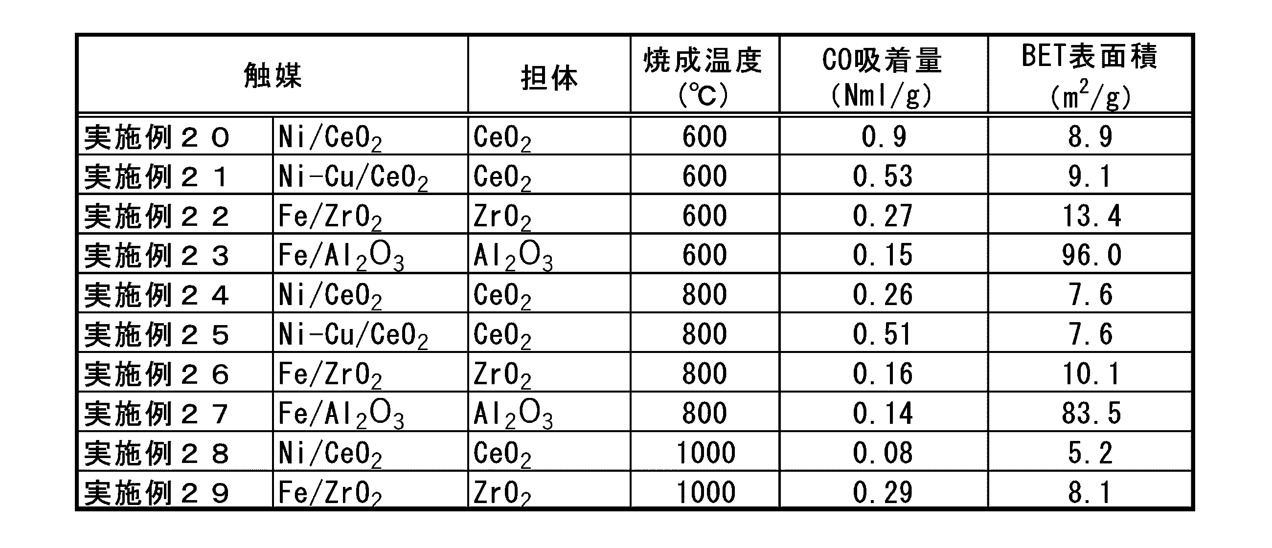
触媒活性試験は、H2とCO2が1:1(体積比)で含まれる混合ガスを反応ガスとして用い、GHSVを10000/hの条件で、反応温度を600℃~800℃まで50℃刻みで変えながら行った。
なお、触媒活性試験を行う前に、水素ガスを触媒層に通流しながら600℃で触媒の還元前処理を行った。
試験結果として、CO2転化率(%)と共に、反応部出口のCO濃度(%)、CH4濃度(%)を表4に記載した。 (Catalytic activity test)
In the catalytic activity test, a mixed gas containing H 2 and CO 2 in a ratio of 1: 1 (volume ratio) was used as the reaction gas, and the reaction temperature was set in increments of 50 ° C. from 600 ° C. to 800 ° C. under the condition of GHSV of 10000 / h. I went while changing with.
Before conducting the catalytic activity test, the catalyst was pretreated for reduction at 600 ° C. while flowing hydrogen gas through the catalyst layer.
As a test result, the CO concentration (%) and the CH 4 concentration (%) at the outlet of the reaction part are shown in Table 4 together with the CO 2 conversion rate (%).
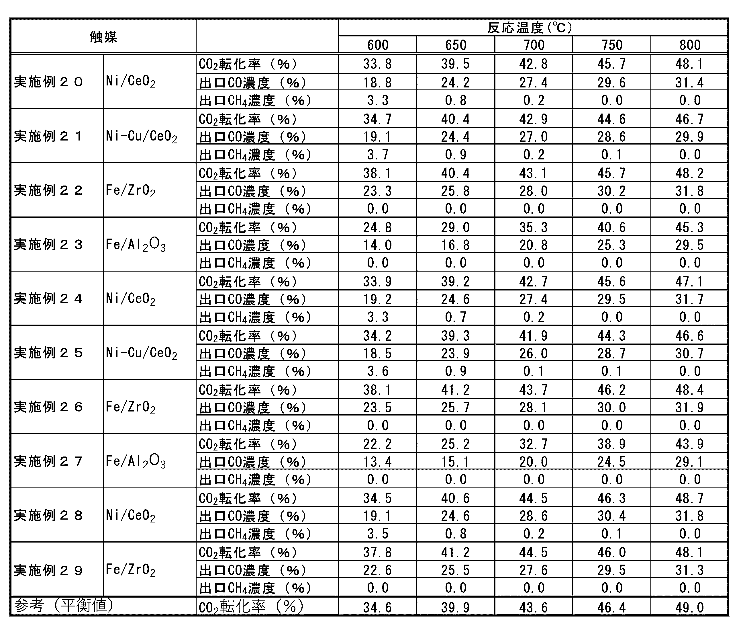
鉄・ジルコニア触媒について、焼成温度を450℃、600℃、800℃、1000℃とした場合の試験結果をそれぞれ実施例8、実施例22、実施例26、実施例29に示している。一方、鉄・アルミナ触媒については、焼成温度を450℃、600℃、800℃とした場合の試験結果をそれぞれ、実施例14、実施例23、実施例27に示している。これらの結果から分かるように、金属担持量は若干異なるが、鉄・ジルコニア触媒は鉄・アルミナ触媒よりも逆水性ガスシフト反応を行う上で、その活性に優れている。また、鉄・ジルコニア触媒は、焼成温度が450℃のもののみならず、600℃、800℃、1000℃と焼成温度を高くしたものでも非常に高い触媒活性を有しており、いずれの焼成温度にした場合でも、CO2転化率が平衡値の近傍に達している。 Iron / Zirconia Catalyst and Iron / Alumina Catalyst The test results of the iron / zirconia catalyst at firing temperatures of 450 ° C, 600 ° C, 800 ° C, and 1000 ° C are shown in Example 8, Example 22, and Example 26, respectively. It is shown in Example 29. On the other hand, for the iron / alumina catalyst, the test results when the firing temperatures are 450 ° C., 600 ° C., and 800 ° C. are shown in Example 14, Example 23, and Example 27, respectively. As can be seen from these results, although the amount of metal supported is slightly different, the iron / zirconia catalyst is superior to the iron / alumina catalyst in performing the reverse water-gas shift reaction. Further, the iron / zirconia catalyst has extremely high catalytic activity not only when the firing temperature is 450 ° C. but also when the firing temperature is as high as 600 ° C., 800 ° C., 1000 ° C., and any firing temperature is used. Even when set to, the CO 2 conversion rate reaches the vicinity of the equilibrium value.
焼成温度を450℃、600℃、800℃、1000℃とした場合の試験結果をそれぞれ実施例4、実施例20、実施例24、実施例28に示している。これらの結果から分かる様に、ニッケル・セリア触媒は、焼成温度が450℃のもののみならず、600℃、800℃、1000℃と焼成温度を高くしたものでも非常に高い触媒活性を有しており、いずれの焼成温度にした場合でも、CO2転化率が平衡値の近傍に達している。 The test results when the nickel / ceria catalyst firing temperature is 450 ° C., 600 ° C., 800 ° C., and 1000 ° C. are shown in Example 4, Example 20, Example 24, and Example 28, respectively. As can be seen from these results, the nickel-ceria catalyst has extremely high catalytic activity not only when the firing temperature is 450 ° C. but also when the firing temperature is as high as 600 ° C., 800 ° C., or 1000 ° C. At any firing temperature, the CO 2 conversion rate reaches near the equilibrium value.
焼成温度を450℃とした場合の試験結果を実施例7に示している。この結果では、ニッケル・アルミナ触媒では、先に述べたニッケル・セリア触媒と比べるとCO2転化率は低い結果となった。 Example 7 shows the test results when the nickel-alumina catalyst firing temperature was 450 ° C. As a result, the CO 2 conversion rate of the nickel-alumina catalyst was lower than that of the nickel-ceria catalyst described above.
焼成温度を450℃、600℃、800℃とした場合の試験結果をそれぞれ実施例6、実施例21、実施例25に示している。これらの結果から、ニッケル・銅・セリア触媒では、焼成温度が600℃や800℃のように高くなると若干CO2転化率が低下する傾向が見られるが、先に述べた焼成温度条件が同様の鉄・アルミナ触媒より優れている。また、焼成温度が450℃のニッケル・銅・セリア触媒では、CO2転化率が平衡値の近傍に達している。 The test results when the nickel / copper / ceria catalyst firing temperatures are 450 ° C., 600 ° C., and 800 ° C. are shown in Example 6, Example 21, and Example 25, respectively. From these results, it can be seen that the CO 2 conversion rate of nickel / copper / ceria catalysts tends to decrease slightly when the firing temperature is as high as 600 ° C or 800 ° C, but the firing temperature conditions described above are the same. Superior to iron / alumina catalysts. Further, in the nickel / copper / ceria catalyst having a firing temperature of 450 ° C., the CO 2 conversion rate reaches the vicinity of the equilibrium value.
以上に示したように、鉄・ジルコニア系触媒やニッケル・セリア系触媒では、焼成温度を450℃~1000℃のように種々変更しても、非常に高い逆水性ガスシフト触媒活性を示すため、例えば600℃~800℃付近の高温域で使用する固体酸化物形の電解セルと組み合わせて使用する場合でも、高い性能と耐久性を確保し易くなり有用である。 Usefulness as a reverse water-gas shift catalyst As shown above, iron-zirconia-based catalysts and nickel-ceria-based catalysts have extremely high reverse water-based catalysts even if the firing temperature is changed to 450 ° C to 1000 ° C. Since it exhibits gas shift catalytic activity, it is useful because it facilitates ensuring high performance and durability even when used in combination with a solid oxide fuel cell used in a high temperature range of, for example, around 600 ° C to 800 ° C.
なお、本実施例の試験は、10000/hという非常に高いGHSV条件で行った試験であるので、GHSVを10000/hよりも小さくした条件、すなわち、処理するガス量に対して使用する触媒量を増やすことで、より高いCO2転化率(%)で逆水性ガスシフト反応を行うことも可能となる。 By using the reverse water-gas shift catalyst cat1 in the first catalyst reaction unit 20 (reverse water-gas shift reaction unit), it is equivalent to the Pt catalyst, which has high activity but is very expensive at around 600 to 1000 ° C. The reverse water-gas shift reaction can be carried out at the above CO2 conversion rate (%).
Since the test of this example was performed under a very high GHSV condition of 10000 / h, the GHSV was made smaller than 10000 / h, that is, the amount of catalyst used for the amount of gas to be treated. It is also possible to carry out a reverse water-gas shift reaction with a higher CO 2 conversion rate (%).
これまでの説明では、図1に示すシステム構成に従って、ガスの移流方向に沿って電解反応部10と逆水性ガスシフト反応部20とを記載順に個別に設ける構成に沿って説明した。
電解反応部10の反応は反応条件によっては発熱反応となり、逆水性ガスシフト反応部20の反応は吸熱反応である。そこで、これら二つの反応部10、20を一体化することでシステムの熱効率を高めることができる。このように、これら二つの反応部10、20を組み合わせて、一体化する場合の構成を示したのが図3であり、一体とされていることを両部位を囲って示している。また、同箱内にこのように一体化された場合の反応を示した。基本的には、先に示した式1、式2、式3が行われることとなる。なお、電解反応部10と逆水性ガスシフト反応部20を組み合わせて、一体化する場合、それらを断熱性部材で共に囲うと、電解反応部10と逆水性ガスシフト反応部20との間の熱の授受を効率良く行えるので好ましい。また、電解反応部10で発生する熱を逆水性ガスシフト反応部20に伝熱させるために伝熱性部材を用いて電解反応部10と逆水性ガスシフト反応部20とを接続させても良い。 [Combination of electrolytic reaction section and reverse water-gas shift reaction section]
In the description so far, according to the system configuration shown in FIG. 1, the
The reaction of the
上記概念に基づいて、電解反応部10となっている電解セルユニットUに、逆水性ガスシフト反応部20を設けることが好ましい。これは、電解セル1として600~800℃付近において作動する固体酸化物形電解セルを用いた場合、600~800℃付近において高い活性が得られる本願の逆水性ガスシフト触媒cat1では、電解反応部10と逆水性ガスシフト反応部20とを同程度の温度域で使用できるからである。
この場合も、電解反応部10を通過したガスが逆水性ガスシフト反応部20に導かれて逆水性ガスシフト反応を発生できればよい。 [Electrolytic cell unit equipped with both an electrolytic reaction unit and a reverse water-gas shift reaction unit]
Based on the above concept, it is preferable to provide the reverse water-gas
In this case as well, it is sufficient that the gas that has passed through the
即ち、この電解セルユニットUも、電解質層1aを挟んで電極層2と対極電極層3が形成された電解セル1、その支持体としての機能を有するとともに、セパレータとして働く金属支持体4、供給路形成部材5、6を備えて構成されており、電極層側ガス供給路5a及び対極電極層側ガス供給路6aが形成される構成とされている。さらに詳細に説明すると、図からも判明するように、金属支持体4をガスの移流方向でみると、電解セル1に対応する部位には孔4aを設けているが、電極層2より下流側には孔を設けてはいない。従って、金属支持体4は、上記の電極層2に供給されるとともにこの電極層2から放出されるガスと、対極電極層3ガスに供給されるとともにこの対極電極層3から放出されるガスとを、有効に分離するセパレータとなる。 As shown in the figure, the cross section of the electrolytic cell unit U is basically the same.
That is, this electrolytic cell unit U also has an
さらに、電極層側ガス供給路5aは、電解反応部10を超えて先に延ばされており、この延長側にも、前記塗布層20aを設けている。 However, in this example, the inner surface of the electrode layer side
Further, the electrode layer side
このようにして構成される電解セルユニットUを、図2、図4の左右方向に積層することで、多数の電解セルユニットUが積層され、それらが電気的に接続された所謂電解セルモジュール(図示省略)を形成することができる。当然、生成される有用なガスは複数層に渡って得ることができる。 In this arrangement, it is configured to act as a separator for separating the O2 generated with H 2 and a
By stacking the electrolytic cell units U configured in this manner in the left-right directions of FIGS. 2 and 4, a large number of electrolytic cell units U are laminated, and the so-called electrolytic cell modules (the so-called electrolytic cell modules) to which they are electrically connected are laminated. (Not shown) can be formed. Of course, the useful gas produced can be obtained over multiple layers.
図5に、この実験に供した電解セルユニットUの断面を示した。 Under the concept of combining the
FIG. 5 shows a cross section of the electrolytic cell unit U used in this experiment.
ここでは、電解セル1として、金属支持型の固体酸化物形電解セルを用いた。金属支持体4として、厚さ0.3mmのフェライト系ステンレスの金属板に対して、レーザー加工により貫通孔(孔4aとなる)を複数設けて、金属基板を作製した。この金属基板の上に、電極層2と中間層2aを順に積層し、金属基板の中間層2aの上に、中間層2aを覆うように電解質層1aを積層した。更に、電解質層1aの上に、反応防止層7と対極電極層3を順に積層し、電解セル1を作製した。なお、電極層2を形成する材料としてはNiO粉末とGDC粉末の混合物を用い、中間層2aを形成する材料としてはGDC粉末を用い、電解質層1aを形成する材料としては8YSZ(8mol%イットリア安定化ジルコニア)粉末を用い、反応防止層7を形成する材料としてはGDC粉末を用い、対極電極層3を形成する材料としてはGDC粉末とLSCF粉末の混合物を用いた。また、電極層2、中間層2a、電解質層1a、反応防止層7、対極電極層3の厚さが、それぞれ約25μm程度、約10μm程度、約5μm程度、約5μm程度、約20μm程度であった。なお、電極層2と電解質層1aの間に中間層2aを設けたり、電解質層1aと対極電極層3の間に反応防止層7を設けたりすることで、電解セル1の性能や耐久性を向上することができる。また、中間層2aや反応防止層7は、低温焼成法(例えば1100℃より高い高温域での焼成処理をしない低温域での焼成処理を用いる湿式法)やスプレーコーティング法(溶射法やエアロゾルデポジション法、エアロゾルガスデポジッション法、パウダージェットデポジッション法、パーティクルジェットデポジション法、コールドスプレー法などの方法)、PVD法(スパッタリング法やパルスレーザーデポジション法など)、CVD法などにより形成することが好ましい。これらの、低温域で使用可能なプロセスにより、例えば1100℃より高い高温域での焼成を用いずに、良好な中間層2aや反応防止層7が得られる。そのため、金属支持体4を傷めることなく、性能や耐久性に優れた電解セル1を実現できるので好ましい。更に、低温焼成法を用いると、原材料のハンドリングが容易になるので更に好ましい。 Hereinafter, a specific description will be given with reference to FIG. The figure shows a cross-sectional view of the electrolytic cell unit U.
Here, as the
電解セルユニットUにH2OとCO2を含むガスを供給しながら電解反応を行い、電解セルユニットUの出口ガスのH2とCOの比をガスクロマトグラフを用いて測定した。結果を以下の表5に示した。この実験結果を比較例A1,A2と記載した。 Results when the reverse water-gas shift catalyst cat1 is not stored The electrolytic reaction is performed while supplying gas containing H 2 O and CO 2 to the electrolytic cell unit U, and the ratio of H 2 to CO of the outlet gas of the electrolytic cell unit U. Was measured using a gas chromatograph. The results are shown in Table 5 below. The experimental results are described as Comparative Examples A1 and A2.
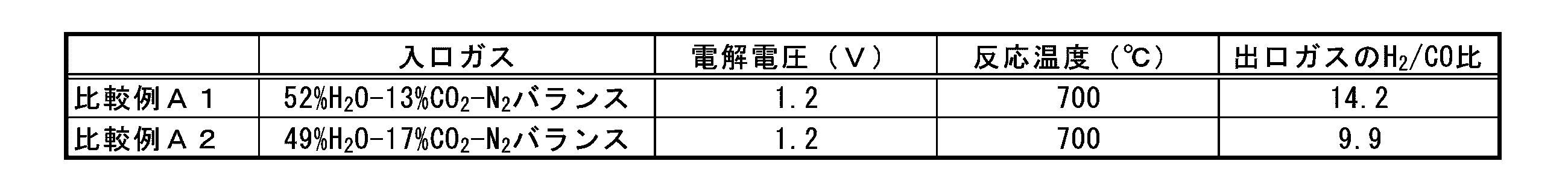
逆水性ガスシフト触媒cat1として、実施例2と同様の8YSZ担体にNiを約10%担持して得た粒状の触媒を収納して、電解セルユニットUにH2OとCO2を含むガスを供給しながら電解反応を行い、電解セルユニットUの出口ガスのH2とCOの比をガスクロマトグラフを用いて測定した。その結果を表6に示した。この実験結果を実施例A1と記載した。 Results when the reverse water gas shift catalyst cat1 is stored As the reverse water gas shift catalyst cat1, a granular catalyst obtained by supporting about 10% of Ni on the same 8YSZ carrier as in Example 2 is stored in the electrolytic cell unit U. The electrolytic reaction was carried out while supplying a gas containing H 2 O and CO 2 , and the ratio of H 2 to CO of the outlet gas of the electrolytic cell unit U was measured using a gas chromatograph. The results are shown in Table 6. The experimental result is described as Example A1.
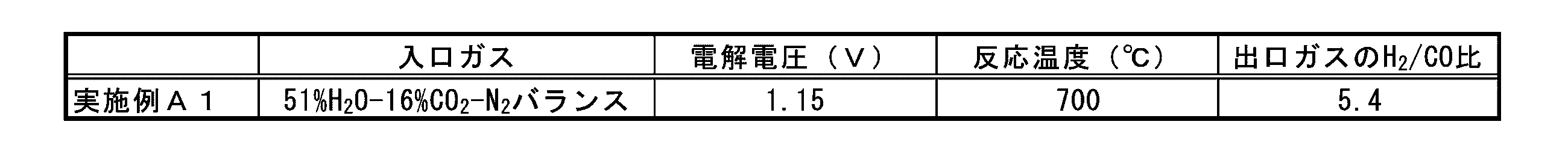
なお、電解反応部10に導入するH2OとCO2の比率や電解反応部10の反応条件(電解電圧や反応温度等)、逆水性ガスシフト反応部20の反応条件(使用触媒量やGHSV、反応温度等)などを適宜調整することで、逆水性ガスシフト反応部20の出口での水素/一酸化炭素([H2/CO])比を、後段の第2触媒反応部30(炭化水素合成反応部)に適した値(例えば、COのメタン化反応の当量比であるH2/CO=3など)に調整することができる。 A comparison between the electrolytic cell unit U, which does not store the reverse water-gas shift catalyst cat1 in the electrode layer side
The ratio of H 2 O and CO 2 introduced into the
これまでの説明では、電解反応部10と第一触媒反応部(逆水性ガスシフト反応部)20とを、一体化する例に関して主に説明したが、両部位10、20を別部位としておき、両部位10、20間に熱交換器11を設けて、両部位間で熱融通が可能な構成を採用してもよい。この構成を図1に対応して図6に示した。中抜きの二重線は両部位間での熱移動を示している。この構成では、各部位10、20の温度を適切に制御できる。 [Install a heat exchanger between the electrolytic reaction section and the reverse water-gas shift reaction section]
In the explanation so far, the example in which the
この第2触媒反応部30(炭化水素合成反応部)では、少なくともH2とCOが流入され、触媒反応により炭化水素類(メタンやカーボン数が2以上の様々な炭化水素)等を生成する。 [Second catalytic reaction section (hydrocarbon synthesis reaction section)]
At least H 2 and CO flow into the second catalytic reaction unit 30 (hydrocarbon synthesis reaction unit), and hydrocarbons (methane and various hydrocarbons having 2 or more carbon atoms) and the like are produced by the catalytic reaction.
この第2触媒反応部30に使用する触媒(炭化水素合成触媒cat2)の活性試験として、発明者らは以下に示す評価試験1、評価試験2、評価試験3、評価試験4及び評価試験5を行った。ここで、評価試験1~4は製造するガスとして所望のカロリー数以上のガス(高カロリーガスと呼ぶ)が得られるかどうかの試験であり、評価試験5は、製造時に同時に得られる重質炭化水素の確認試験である。 (Example of hydrocarbon synthesis catalyst)
As an activity test of the catalyst (hydrocarbon synthesis catalyst cat2) used in the second
炭化水素合成触媒cat2の調製も、図11、12で説明した採用する手法とする。
即ち、目的とする触媒の組成に従って、水溶性のルテニウム化合物(硝酸ルテニウム、塩化ルテニウム、硫酸ルテニウム、硫酸ルテニウムアンモニウム、酢酸ルテニウム、シュウ酸ルテニウム、クエン酸ルテニウム等)を定量し溶かした水溶液を得る。また、更なる触媒活性成分としてモリブデン、バナジウム、鉄、コバルトを担持する際には水溶性のこれら金属化合物を同様に定量し、溶かした水溶液を得る。当該水溶液を用いて、例えばその水溶液に所定量の担体粒(ZrO2、Al2O3、SiO2、MgO、TiO2)を投入し、触媒活性成分を含浸担持し、乾燥処理や焼成処理、還元処理等の必要な処理工程を施して炭化水素合成触媒cat2を得ることができる。
なお、下記の実施例の触媒は、塩化ルテニウム水溶液、モリブデン酸アンモニウム水溶液、シュウ酸バナジル水溶液、硝酸鉄水溶液、硝酸コバルト水溶液をそれぞれ用い、ルテニウムとルテニウム以外の触媒活性成分を両方担持する場合は、逐次担持法(ルテニウム以外の触媒活性成分を担体にまず担持し、その後にルテニウムを担持する2段階の担持法)を用いて調製した。
評価試験5に関しては、別に記載した。 (Catalyst preparation)
The preparation of the hydrocarbon synthesis catalyst cat2 is also the method adopted as described in FIGS. 11 and 12.
That is, an aqueous solution obtained by quantifying and dissolving a water-soluble ruthenium compound (ruthenium nitrate, ruthenium chloride, ruthenium sulfate, ruthenium ammonium sulfate, ruthenium acetate, ruthenium oxalate, ruthenium citrate, etc.) according to the composition of the target catalyst is obtained. Further, when molybdenum, vanadium, iron, and cobalt are supported as further catalytically active components, these water-soluble metal compounds are similarly quantified to obtain a dissolved aqueous solution. Using the aqueous solution, for example, a predetermined amount of carrier particles (ZrO 2 , Al 2 O 3 , SiO 2 , MgO, TiO 2 ) are added to the aqueous solution, impregnated and supported with a catalytically active component, and dried or fired. The hydrocarbon synthesis catalyst cat2 can be obtained by performing a necessary treatment step such as a reduction treatment.
In addition, as the catalyst of the following Examples, an aqueous solution of ruthenium chloride, an aqueous solution of ammonium molybdate, an aqueous solution of vanadyl oxalate, an aqueous solution of iron nitrate, and an aqueous solution of cobalt nitrate are used, respectively. It was prepared using a sequential carrier method (a two-step carrier method in which a catalytically active ingredient other than ruthenium is first supported on a carrier and then ruthenium is supported).
評価試験1では、COを12.4%、CO2を24.8%、H2を37.2%、H2Oを12.4%を含み、残部をN2とした混合ガスを反応ガスに用い、GHSVを4000/h(WETベース)とし、275℃~360℃の間の反応温度で炭化水素合成触媒cat2の活性試験を行った。なお、この場合の反応ガスは、電解反応部10で水と二酸化炭素の共電解反応を二酸化炭素の電解反応率が低い条件で行われ、その後段に設置された逆水性ガスシフト反応部20において二酸化炭素の逆水性ガスシフト反応が行われた後のCO、CO2、H2、H2Oの混合ガスを炭化水素合成反応部30に導入して炭化水素合成反応を実施するモデルを想定したものの一例である。 (Evaluation test 1)
In the
この指標は、触媒反応で得られた炭化水素合成反応部30の出口ガスからCO2を除いた場合の炭化水素への変換率を示す指標となり、この指標が高いことが好ましい。 1. 1. Estimated hydrocarbon conversion rate for CO 2 removal = [Number of carbons in hydrocarbons in outlet gas] / [Number of carbons in outlet gas-Number of carbons in outlet CO 2 ]
This index is an index showing the conversion rate to hydrocarbons when CO 2 is removed from the outlet gas of the hydrocarbon
Nn [mol]:触媒反応部ガス中のCn炭化水素のモル数(n=1~4)
HN [MJ / m3(N)]:触媒反応部ガス中のCn炭化水素の発熱量
〔H1 = 39.8、H2 = 69.7、H3 = 99.1、H4 = 128.5〕
この指標は、触媒反応で得られた炭化水素合成反応部30の出口ガス中に含まれるC1~C4成分の量を示す指標となり、この値が39.8を超える場合、メタン以外にもエタンやプロパン、ブタンなどの炭化水素類が生成していることが確認できる。 2. C1-C4 calorific value (MJ / Nm 3 ) = Σ (Nn × HN) / Σ Nn
Nn [mol]: Number of moles of Cn hydrocarbon in catalyst reaction gas (n = 1 to 4)
HN [MJ / m 3 (N)]: Calorific value of Cn hydrocarbons in the catalyst reaction gas [H1 = 39.8, H2 = 69.7, H3 = 99.1, H4 = 128.5]
This index is an index showing the amount of C1 to C4 components contained in the outlet gas of the hydrocarbon
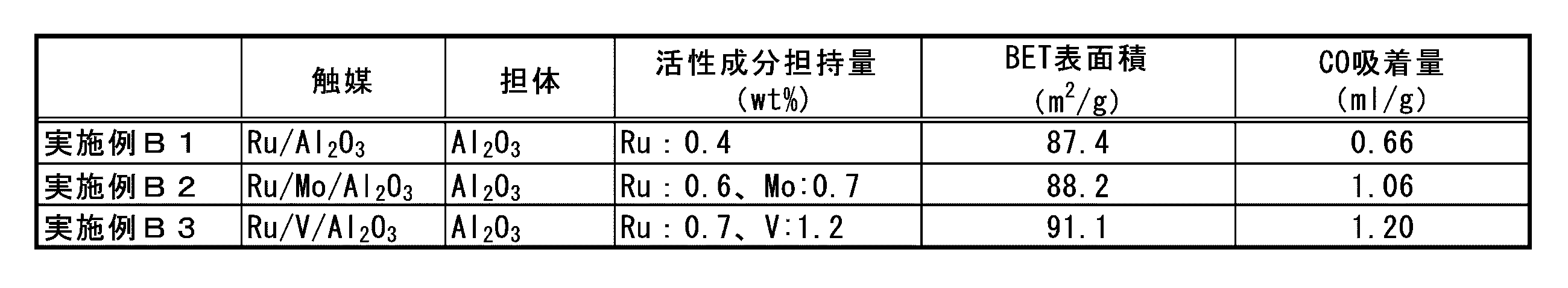

以上の結果から、上記の炭化水素製造システム100により、C1-C4発熱量が39MJ/Nm3以上の高カロリーガスを生成し得ることが確認できた。 As shown in Tables 7 and 8, from a mixed gas of CO, CO 2 , H 2 , and H 2 O, as a hydrocarbon synthesis catalyst cat2, a catalyst in which ruthenium is supported on an alumina carrier, molybdenum in addition to ruthenium, or It was confirmed that hydrocarbons can be synthesized using a catalyst supporting vanadium.
From the above results, it was confirmed that the above-mentioned
評価試験2では、COを0.45%、CO2を18.0%、H2を71.55%、H2Oを10.0%を含む混合ガスを反応ガスに用い、GHSVを5000/h(DRYベース)とし、約230℃~約330℃の間の反応温度で炭化水素合成触媒cat2の活性試験を行った。なお、この場合の反応ガスは、電解反応部10で水と二酸化炭素の共電解反応を二酸化炭素の電解反応率が低い条件で行われた場合に得られる混合ガスを炭化水素合成反応部30に導入して炭化水素合成反応を実施するモデルを想定したものの一例である。 (Evaluation test 2)
In
この指標は、流入される全炭素の内、CO2に変換されることなく炭化水素に変換された炭素数の割合を示す指標となり、この指標が高いことが好ましい。 1 Hydrocarbon conversion rate = [Number of carbons in hydrocarbons in outlet gas] / [Number of carbons in outlet gas]
This index is an index indicating the ratio of the number of carbon atoms converted into hydrocarbons without being converted into CO 2 among the total carbons flowing in, and it is preferable that this index is high.
この指標は、触媒反応で得られた炭化水素合成反応部の出口ガスからCO2を除いた場合の炭化水素への変換率を示す指標となり、この指標も高いことが好ましい。 2 Estimated hydrocarbon conversion rate for CO 2 removal = [Number of carbons in hydrocarbons in outlet gas] / [Number of carbons in outlet gas-Number of carbons in outlet CO 2 ]
This index is an index showing the conversion rate to hydrocarbons when CO 2 is removed from the outlet gas of the hydrocarbon synthesis reaction part obtained by the catalytic reaction, and it is preferable that this index is also high.

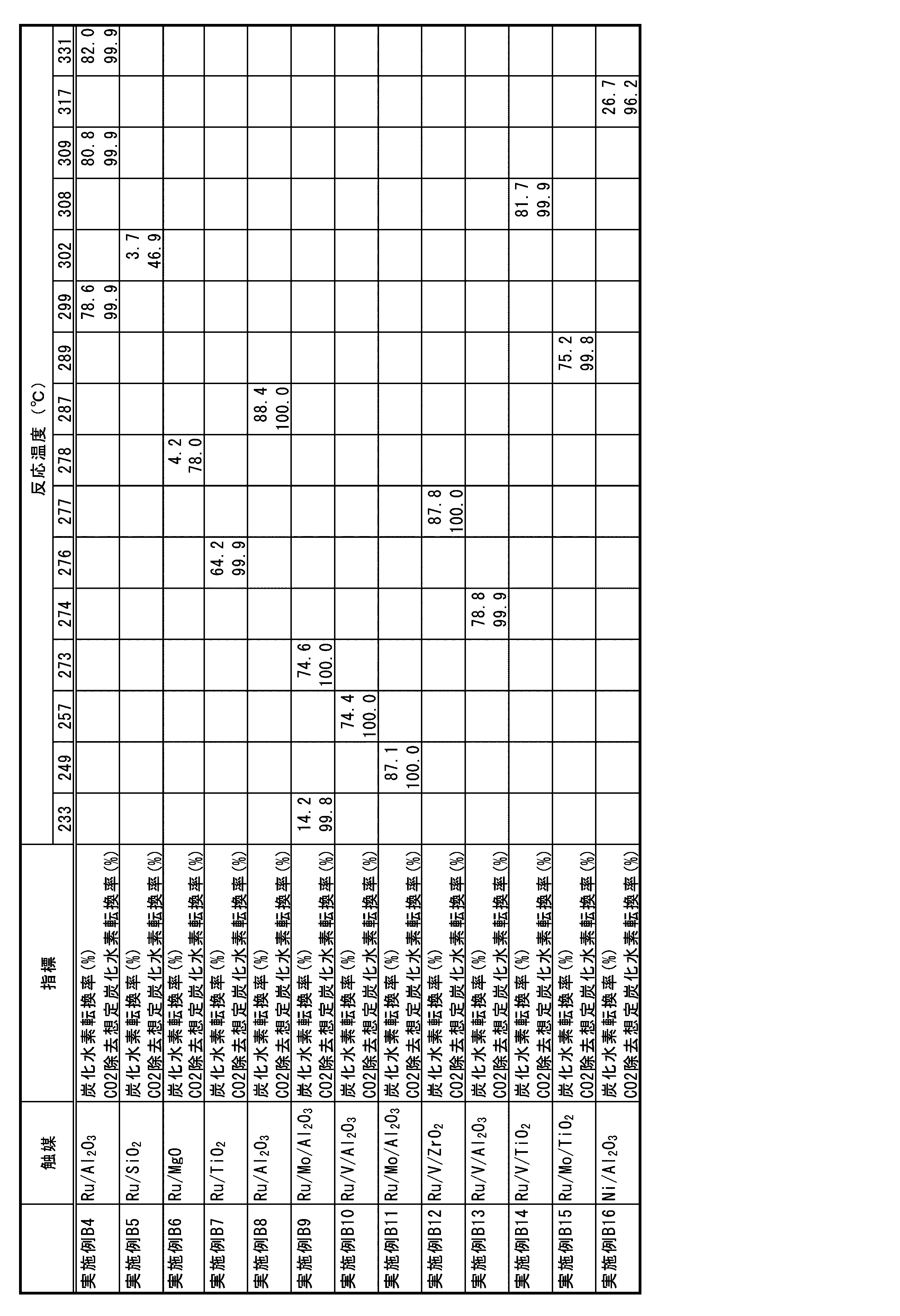
評価試験3では、H2とCOが3:1(体積比)で含まれる混合ガス(H2/CO=3)を反応ガスに用い、GHSVを2000/hとし、235℃~約330℃の間の反応温度で炭化水素合成触媒cat2の活性試験を行った。この活性試験では、チタニア担体にルテニウムに加えて鉄もしくはコバルトを担持した触媒(実施例B17,B18)を用いた。なお、この場合の反応ガスは、電解反応部10で水の電気分解を行って得た水素に一酸化炭素を添加した混合ガスや、水と二酸化炭素の共電解反応を行って得たガスから必要に応じて水分を分離したり二酸化炭素を分離したりして得た水素と一酸化炭素の混合ガスを炭化水素合成反応部30に導入して炭化水素合成反応を実施するモデルを想定したものの一例である。 (Evaluation test 3)
In the
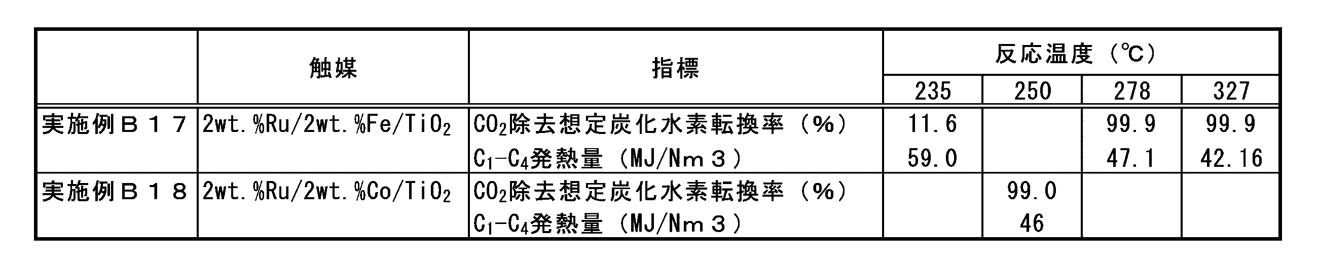
評価試験4では、COを0.5%、CO2を20.0%、H2を79.5%を含む混合ガスを反応ガスに用い、GHSVを5000/h(DRYベース)とし、約260℃~約290℃の間の反応温度で炭化水素合成触媒cat2の活性試験を行った。なお、この場合の反応ガスは、評価試験2で用いた反応ガスから水分を分離除去した混合ガスに相当する。 (Evaluation test 4)
In the
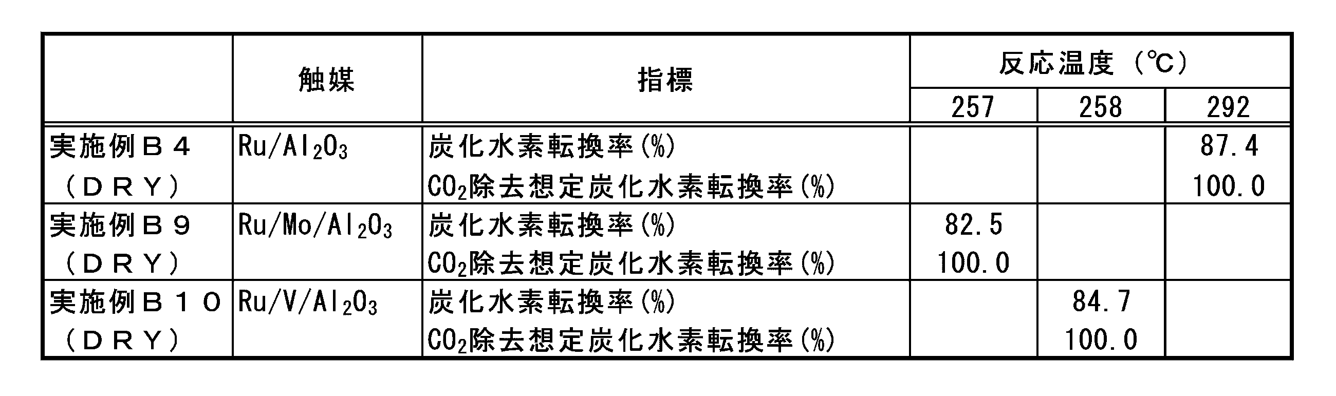
触媒調製
この評価試験5にあっても、炭化水素合成触媒cat2の調製は、図11、12で説明した採用する手法とした。
触媒cat2は、触媒活性成分をルテニウム及び鉄とし担体はチタニアとした。ルテニウム成分の担持工程では塩化ルテニウム水溶液を使用し、鉄成分の担持工程では硝酸鉄水溶液を使用した。その他、先に示したように、その他のルテニウムや鉄を含む化合物の水溶液も使用できる。 (Evaluation test 5)
Catalyst preparation Even in this
In the catalyst cat2, the catalytically active components were ruthenium and iron, and the carrier was titania. An aqueous ruthenium chloride solution was used in the step of supporting the ruthenium component, and an aqueous iron nitrate solution was used in the step of supporting the iron component. In addition, as shown above, aqueous solutions of other compounds containing ruthenium and iron can also be used.
所定濃度の鉄含有水溶液を金属酸化物担体としてのチタニア担体に含浸させ、チタニア担体に鉄を担持させた。この鉄担持チタニアに、所定濃度の塩化ルテニウム水溶液を含浸させた。その後、ヒドラジン水溶液を用いて湿式還元処理を行い、炭化水素合成触媒cat2として鉄-ルテニウム担持チタニアを得た。 The specific preparation method is as follows.
A titania carrier as a metal oxide carrier was impregnated with an iron-containing aqueous solution having a predetermined concentration, and iron was supported on the titania carrier. This iron-supported titania was impregnated with an aqueous solution of ruthenium chloride having a predetermined concentration. Then, a wet reduction treatment was carried out using an aqueous hydrazine solution to obtain iron-ruthenium-supported titania as a hydrocarbon synthesis catalyst cat2.
試験に際しては、図12(b)に示す還元前処理を行った。
具体的には水素を10%含有する窒素ガスを水素含有ガスとして炭化水素合成反応部30となる触媒収納部に流しながら、触媒部の温度を350℃に保持し、1時間、触媒の使用前水素処理(還元前処理)を行った。
ここで還元前処理で用いる水素含有ガスは、このように、水素と窒素との混合ガスとすることで水素の消費量を少なくすることができる。よって、この還元前処理では、例えば水素濃度を20体積%以下とする水素と窒素との混合ガスとすることが好ましく、本実施形態では、10体積%の水素を含み残余が窒素ガスである水素含有ガスを使用して、炭化水素合成触媒cat2の還元前処理を行うこととした。 In the reduction pretreatment test, the reduction pretreatment shown in FIG. 12 (b) was performed.
Specifically, while flowing nitrogen gas containing 10% hydrogen as hydrogen-containing gas through the catalyst storage section which becomes the hydrocarbon
Here, the hydrogen-containing gas used in the reduction pretreatment can be reduced in hydrogen consumption by using a mixed gas of hydrogen and nitrogen in this way. Therefore, in this reduction pretreatment, for example, it is preferable to use a mixed gas of hydrogen and nitrogen having a hydrogen concentration of 20% by volume or less, and in the present embodiment, hydrogen containing 10% by volume of hydrogen and the remainder being nitrogen gas. It was decided to perform the reduction pretreatment of the hydrocarbon synthesis catalyst cat2 using the contained gas.
評価試験5では、H2とCOが3:1(体積比)で含まれる混合ガス(H2/CO=3)を反応ガスに用い、GHSV=2000/hの条件で炭化水素合成触媒cat2の試験を行った。因みに、この試験での反応圧力は0.6MPaとした。 Test conditions In the
上記還元前処理を実行した炭化水素合成触媒cat2(2wt.%Ru/2wt.%Fe/TiO2)を使用して、炭化水素合成試験を反応温度275℃で約80時間行った。その結果、触媒反応部の出口では、継続的に、メタン(CH4)を主成分とし、エタンやプロパン、ブタン等のC2~C6の炭化水素が生成していることをガスクロマトグラフを用いたガス分析により確認した。
一方、その触媒反応部の下側に設けた空冷部位(重質炭化水素分離部35に相当する部位)で得られたワックス状の析出物を分析したところ、IRとC13NMR分析より、直鎖高級脂肪族炭化水素(平均鎖長:C26)と同定できた。
また、炭化水素合成触媒cat2上の析出物を溶媒抽出してMS分析したところ、268~604で14マスユニット毎にピーク(352の強度が最大)が得られた。この結果から、炭化水素合成触媒cat2上にはC19~C43(C25が最も多い)の高級炭化水素が析出していることが分かった。 Heavy
A hydrocarbon synthesis test was carried out at a reaction temperature of 275 ° C. for about 80 hours using the hydrocarbon synthesis catalyst cat2 (2 wt.% Ru / 2 wt.% Fe / TiO 2) subjected to the above reduction pretreatment. As a result, a gas using a gas chromatograph shows that methane (CH 4 ) is the main component and C2-C6 hydrocarbons such as ethane, propane, and butane are continuously produced at the outlet of the catalytic reaction section. Confirmed by analysis.
On the other hand, when the wax-like precipitates obtained at the air-cooled part (the part corresponding to the heavy hydrocarbon separation part 35) provided under the catalytic reaction part were analyzed, the linear higher grade was obtained from the IR and C13 NMR analysis. It could be identified as an aliphatic hydrocarbon (average chain length: C26).
Further, when the precipitate on the hydrocarbon synthesis catalyst cat2 was extracted with a solvent and analyzed by MS, peaks (maximum intensity of 352) were obtained for every 14 mass units in 268 to 604. From this result, it was found that higher hydrocarbons of C19 to C43 (mostly C25) were precipitated on the hydrocarbon synthesis catalyst cat2.
上記試験と同様に炭化水素合成触媒cat2(2wt.%Ru/2wt.%Fe/TiO2)を使用して、その還元前処理を550℃で実行し、炭化水素合成試験を反応温度325℃で約270時間行った。その結果、触媒反応部の出口では、継続的に、メタン(CH4)を主成分とし、エタンやプロパン、ブタン等のC2~C6の炭化水素が生成していることをガスクロマトグラフを用いたガス分析により確認した。一方、その触媒反応部の下側に設けた空冷部位(重質炭化水素分離部35に相当する部位)において、ワックス状の析出物(直鎖高級脂肪族炭化水素(平均鎖長:C18))が得られることを確認した。更に、炭化水素合成触媒cat2上には、C19~C60(C29が最も多い)の高級炭化水素が析出していることが分かった。 Heavy
Using the hydrocarbon synthesis catalyst cat2 (2 wt.% Ru / 2 wt.% Fe / TiO 2 ) in the same manner as in the above test, the reduction pretreatment was carried out at 550 ° C., and the hydrocarbon synthesis test was carried out at a reaction temperature of 325 ° C. It went for about 270 hours. As a result, a gas using a gas chromatograph shows that methane (CH 4 ) is the main component and C2-C6 hydrocarbons such as ethane, propane, and butane are continuously produced at the outlet of the catalytic reaction section. Confirmed by analysis. On the other hand, a wax-like precipitate (linear higher aliphatic hydrocarbon (average chain length: C18)) is provided at an air-cooled portion (a portion corresponding to the heavy hydrocarbon separating portion 35) provided below the catalytic reaction portion. Was confirmed to be obtained. Furthermore, it was found that higher hydrocarbons of C19 to C60 (mostly C29) were precipitated on the hydrocarbon synthesis catalyst cat2.
さらに、上記の炭化水素合成触媒cat2(2wt.%Ru/2wt.%Fe/TiO2)とは異なる別の炭化水素合成触媒cat2(2wt.%Ru/2wt.%Co/TiO2)を用いて、その還元前処理を450℃で実行し、炭化水素合成試験を250℃~270℃の温度で約380時間行った。その結果、触媒反応部の出口では、継続的に、メタン(CH4)を主成分とし、エタンやプロパン、ブタン等の炭化水素が生成していることをガスクロマトグラフを用いたガス分析により確認した。一方、その触媒反応部の下側に設けた空冷部位(重質炭化水素分離部35に相当する部位)において、ワックス状の析出物(直鎖高級脂肪族炭化水素(平均鎖長:C27))が得られることを確認した。更に、炭化水素合成触媒cat2上には、C23~C60(C37が最も多い)の高級炭化水素が析出していることが分かった。 Production of Hydrocarbons with Another Hydrocarbon Synthesis Catalyst Further, another hydrocarbon synthesis catalyst cat2 (2 wt.% Ru) different from the above hydrocarbon synthesis catalyst cat2 (2 wt.% Ru / 2 wt.% Fe / TiO 2) Using / 2 wt.% Co / TiO 2), the reduction pretreatment was carried out at 450 ° C., and the hydrocarbon synthesis test was carried out at a temperature of 250 ° C. to 270 ° C. for about 380 hours. As a result, it was confirmed by gas analysis using a gas chromatograph that methane (CH 4 ) was the main component and hydrocarbons such as ethane, propane, and butane were continuously produced at the outlet of the catalytic reaction section. .. On the other hand, a wax-like precipitate (linear higher aliphatic hydrocarbon (average chain length: C27)) in an air-cooled portion (a portion corresponding to the heavy hydrocarbon separating portion 35) provided below the catalytic reaction portion. Was confirmed to be obtained. Furthermore, it was found that higher hydrocarbons of C23 to C60 (mostly C37) were precipitated on the hydrocarbon synthesis catalyst cat2.
この重質炭化水素分離部35に至るガスは冷却されることにより、炭化水素合成反応部30から放出されるガスに含有される重質炭化水素が凝縮し、重質炭化水素を外部に取出すことができる。例えば、上記に示した2wt.%Ru/2wt.%Fe/TiO2触媒を用いた炭化水素合成反応部30において、H2とCOが3:1(体積比)で含まれる混合ガス(H2/CO=3)を導入して、275℃で反応を行ったところ、重質炭化水素分離部35において平均鎖長炭素数26の直鎖高級脂肪族炭化水素を取り出すことができ、325℃で反応を行ったところ、重質炭化水素分離部35において平均鎖長炭素数18の直鎖高級脂肪族炭化水素を取り出すことができた。 [Heavy hydrocarbon separator]
By cooling the gas reaching the heavy
この水分離部40には凝縮器を配しており、流入されるH2Oを含有するガスを所定の温度・圧力に調整して、凝縮させ水を外部に取出す。 [Water separator]
The
例えば、この部位50にはPSAを配しており、流入されるCO2を含有するガスから所定の温度・圧力下で吸着剤に吸着してCO2を分離するとともに、分離されたCO2を吸着剤から脱離させることで、CO2を良好に分離する。分離されたCO2は二酸化炭素戻し路51を介して、電解反応部10の前に戻して再利用することができる。
なお、PSA等を用いて、二酸化炭素分離部と水分離部を同一の分離部とすることもできる。 [Carbon dioxide separator]
For example, this
It is also possible to use PSA or the like to make the carbon dioxide separation part and the water separation part the same separation part.
(1)上記の実施形態では、二酸化炭素分離部50において分離されたCO2を電解反応部10の前に戻したが、本発明に係る炭化水素製造システム100では、CO2のCOへの変換は主に逆水性ガスシフト反応部20で行うため、CO2の戻り先を逆水性ガスシフト反応部20の前としても良い。この構成を図7に示した。 [Another Embodiment]
(1) In the above embodiment, the CO 2 separated in the carbon
この構成の場合も、これら各反応部10、20、30は金属支持体4、供給路形成部材5上に構成することができ、この金属支持体aは、生成される炭化水素と酸素とを分離するセパレータとして働くこととなっている。 (6) In the above embodiment, the
Also in the case of this configuration, each of these
このように、本発明に係る炭化水素製造システム(高カロリーガス製造システムとなる)を電解反応部10と炭化水素合成反応部30とで構築する場合に、炭化水素合成反応部を複数段としてもよい。図15には、炭化水素合成反応部30を二段(30a、30b)とした例を示している。このようにすることで、異なった炭化水素合成反応部30に異なった炭化水素合成触媒cat2を配置して、異なった温度域で作動させることもできる。 (7) In the above embodiment, the
As described above, when the hydrocarbon production system (which becomes a high-calorie gas production system) according to the present invention is constructed by the
1a 電解質層
2 電極層
3 対極電極層
4 金属支持体(支持体・セパレータ)
4a 孔
5 供給路形成部材(セパレータ)
6 供給路形成部材(セパレータ)
10 電解反応部
20 第1触媒反応部(逆水性ガスシフト反応部)
20a 塗布層
30 第2触媒反応部(炭化水素合成反応部)
40 水分離部
50 二酸化炭素分離部
60 水素分離部
U 電解セルユニット
cat1逆水性ガスシフト触媒
ca1 触媒活性成分(金属成分)
cb1 担体(金属酸化物)
cat2炭化水素合成触媒
ca2 触媒活性成分(金属成分)
cb2 担体(金属酸化物)
1
6 Supply path forming member (separator)
10
40
cb1 carrier (metal oxide)
cat2 hydrocarbon synthesis catalyst ca2 catalytically active component (metal component)
cb2 carrier (metal oxide)
Claims (11)
- 電解反応によって水を水素に変換する、若しくは、電解反応によって水及び二酸化炭素を水素及び一酸化炭素に変換する電解反応部と、前記電解反応部で生成する生成物を触媒反応によって炭化水素に変換する触媒反応部と、前記触媒反応部の出口成分の一部を分岐する分岐路を備えた炭化水素製造システム。 An electrolytic reaction section that converts water to hydrogen by an electrolytic reaction, or water and carbon dioxide to hydrogen and carbon monoxide by an electrolytic reaction, and a product produced by the electrolytic reaction section are converted to hydrocarbons by a catalytic reaction. A hydrogen production system including a catalytic reaction section and a branch path for branching a part of the outlet component of the catalytic reaction section.
- 前記触媒反応部が、前記電解反応部で生成する生成物を使用して触媒反応によって、低級飽和炭化水素を少なくとも含む高カロリーガスに変換する請求項1記載の炭化水素製造システム。 The hydrocarbon production system according to claim 1, wherein the catalytic reaction unit converts a product produced in the electrolytic reaction unit into a high-calorie gas containing at least a lower saturated hydrocarbon by a catalytic reaction.
- 前記触媒反応部の出口成分から二酸化炭素を分離する二酸化炭素分離部を備え、分離された二酸化炭素が前記分岐路より排出される請求項1または2記載の炭化水素製造システム。 The hydrocarbon production system according to claim 1 or 2, further comprising a carbon dioxide separation unit that separates carbon dioxide from the outlet component of the catalytic reaction unit, and the separated carbon dioxide is discharged from the branch path.
- 前記触媒反応部の出口成分から水素を分離する水素分離部を備え、分離された水素が前記分岐路より排出される請求項1~3の何れか一項記載の炭化水素製造システム。 The hydrocarbon production system according to any one of claims 1 to 3, further comprising a hydrogen separation unit that separates hydrogen from the outlet component of the catalytic reaction unit, and the separated hydrogen is discharged from the branch path.
- 前記触媒反応部の出口成分または入口成分の少なくとも何れかから水分を分離する水分離部を備え、分離された水分が前記分岐路より排出される請求項1~4の何れか一項記載の炭化水素製造システム。 The hydrocarbon according to any one of claims 1 to 4, further comprising a water separating part that separates water from at least one of the outlet component and the inlet component of the catalytic reaction part, and the separated water is discharged from the branch path. Hydrogen production system.
- 前記分岐路がリサイクルラインとなる請求項1~5の何れか一項記載の炭化水素製造システム。 The hydrocarbon production system according to any one of claims 1 to 5, wherein the branch road is a recycling line.
- 前記触媒反応部の出口成分から重質炭化水素を分離する重質炭化水素分離部を備える請求項1~6の何れか一項記載の炭化水素製造システム。 The hydrocarbon production system according to any one of claims 1 to 6, further comprising a heavy hydrocarbon separating part for separating heavy hydrocarbons from the outlet component of the catalytic reaction part.
- 前記触媒反応部を複数段備える請求項1~7の何れか一項記載の炭化水素製造システム。 The hydrocarbon production system according to any one of claims 1 to 7, further comprising the catalytic reaction unit in a plurality of stages.
- 逆水性ガスシフト反応部を備える請求項1~8の何れか一項記載の炭化水素製造システム。 The hydrocarbon production system according to any one of claims 1 to 8, further comprising a reverse water-gas shift reaction unit.
- 前記電解反応部が、支持体の上に電極層と電解質層と対極電極層が少なくとも形成された電解セルを有する請求項1~9の何れか一項記載の炭化水素製造システム。 The hydrocarbon production system according to any one of claims 1 to 9, wherein the electrolytic reaction unit has an electrolytic cell in which at least an electrode layer, an electrolyte layer, and a counter electrode layer are formed on a support.
- 前記支持体が金属である請求項10記載の炭化水素製造システム。
The hydrocarbon production system according to claim 10, wherein the support is a metal.
Priority Applications (5)
| Application Number | Priority Date | Filing Date | Title |
|---|---|---|---|
| CA3164837A CA3164837A1 (en) | 2020-03-31 | 2021-03-31 | Hydrocarbon production system |
| US17/914,068 US20230149889A1 (en) | 2020-03-31 | 2021-03-31 | Hydrocarbon Production System |
| CN202180025200.0A CN115298153A (en) | 2020-03-31 | 2021-03-31 | Hydrocarbon production system |
| EP21781086.0A EP4129961A4 (en) | 2020-03-31 | 2021-03-31 | Hydrocarbon production system |
| JP2022512677A JPWO2021201192A1 (en) | 2020-03-31 | 2021-03-31 |
Applications Claiming Priority (2)
| Application Number | Priority Date | Filing Date | Title |
|---|---|---|---|
| JP2020-065256 | 2020-03-31 | ||
| JP2020065256 | 2020-03-31 |
Publications (1)
| Publication Number | Publication Date |
|---|---|
| WO2021201192A1 true WO2021201192A1 (en) | 2021-10-07 |
Family
ID=77929208
Family Applications (1)
| Application Number | Title | Priority Date | Filing Date |
|---|---|---|---|
| PCT/JP2021/014083 WO2021201192A1 (en) | 2020-03-31 | 2021-03-31 | Hydrocarbon production system |
Country Status (6)
| Country | Link |
|---|---|
| US (1) | US20230149889A1 (en) |
| EP (1) | EP4129961A4 (en) |
| JP (1) | JPWO2021201192A1 (en) |
| CN (1) | CN115298153A (en) |
| CA (1) | CA3164837A1 (en) |
| WO (1) | WO2021201192A1 (en) |
Cited By (1)
| Publication number | Priority date | Publication date | Assignee | Title |
|---|---|---|---|---|
| WO2023233499A1 (en) * | 2022-05-31 | 2023-12-07 | 三菱電機株式会社 | Methane production system |
Citations (5)
| Publication number | Priority date | Publication date | Assignee | Title |
|---|---|---|---|---|
| WO2007069197A2 (en) * | 2005-12-15 | 2007-06-21 | Sasol Technology (Proprietary) Limited | Production of hydrocarbons from natural gas |
| WO2012003849A1 (en) * | 2010-07-09 | 2012-01-12 | Haldor Topsøe A/S | Process for converting biogas to a gas rich in methane |
| JP2014198789A (en) * | 2013-03-29 | 2014-10-23 | 大阪瓦斯株式会社 | Methane-rich gas production system |
| WO2019077288A1 (en) * | 2017-10-20 | 2019-04-25 | Engie | Method for converting a gas comprising carbon monoxide into methane by means of a catalytic material containing praseodymium and nickel on alumina |
| WO2019189912A1 (en) * | 2018-03-30 | 2019-10-03 | 大阪瓦斯株式会社 | Metal support body for electrochemical element, electrochemical element, electrochemical module, electrochemical device, energy system, solid oxide fuel cell, solid oxide electrolytic cell, and method for manufacturing metal support body |
Family Cites Families (4)
| Publication number | Priority date | Publication date | Assignee | Title |
|---|---|---|---|---|
| SG160406A1 (en) * | 2005-03-16 | 2010-04-29 | Fuelcor Llc | Systems, methods, and compositions for production of synthetic hydrocarbon compounds |
| EP2650401A1 (en) * | 2012-04-10 | 2013-10-16 | Siemens Aktiengesellschaft | Power plant based methanation system |
| DE102013102969A1 (en) * | 2013-03-22 | 2014-09-25 | Sunfire Gmbh | Process for the preparation of predominantly liquid hydrocarbons and arrangement |
| DE102017204981A1 (en) * | 2017-03-24 | 2018-09-27 | Robert Bosch Gmbh | Method for operating a device for the electrochemical conversion of energy, and device which is operated by such a method |
-
2021
- 2021-03-31 CA CA3164837A patent/CA3164837A1/en active Pending
- 2021-03-31 EP EP21781086.0A patent/EP4129961A4/en active Pending
- 2021-03-31 US US17/914,068 patent/US20230149889A1/en active Pending
- 2021-03-31 WO PCT/JP2021/014083 patent/WO2021201192A1/en unknown
- 2021-03-31 CN CN202180025200.0A patent/CN115298153A/en active Pending
- 2021-03-31 JP JP2022512677A patent/JPWO2021201192A1/ja active Pending
Patent Citations (5)
| Publication number | Priority date | Publication date | Assignee | Title |
|---|---|---|---|---|
| WO2007069197A2 (en) * | 2005-12-15 | 2007-06-21 | Sasol Technology (Proprietary) Limited | Production of hydrocarbons from natural gas |
| WO2012003849A1 (en) * | 2010-07-09 | 2012-01-12 | Haldor Topsøe A/S | Process for converting biogas to a gas rich in methane |
| JP2014198789A (en) * | 2013-03-29 | 2014-10-23 | 大阪瓦斯株式会社 | Methane-rich gas production system |
| WO2019077288A1 (en) * | 2017-10-20 | 2019-04-25 | Engie | Method for converting a gas comprising carbon monoxide into methane by means of a catalytic material containing praseodymium and nickel on alumina |
| WO2019189912A1 (en) * | 2018-03-30 | 2019-10-03 | 大阪瓦斯株式会社 | Metal support body for electrochemical element, electrochemical element, electrochemical module, electrochemical device, energy system, solid oxide fuel cell, solid oxide electrolytic cell, and method for manufacturing metal support body |
Non-Patent Citations (1)
| Title |
|---|
| See also references of EP4129961A4 * |
Cited By (1)
| Publication number | Priority date | Publication date | Assignee | Title |
|---|---|---|---|---|
| WO2023233499A1 (en) * | 2022-05-31 | 2023-12-07 | 三菱電機株式会社 | Methane production system |
Also Published As
| Publication number | Publication date |
|---|---|
| EP4129961A4 (en) | 2024-02-07 |
| CA3164837A1 (en) | 2021-10-07 |
| JPWO2021201192A1 (en) | 2021-10-07 |
| US20230149889A1 (en) | 2023-05-18 |
| CN115298153A (en) | 2022-11-04 |
| EP4129961A1 (en) | 2023-02-08 |
Similar Documents
| Publication | Publication Date | Title |
|---|---|---|
| WO2021201190A1 (en) | Reverse water-gas shift catalyst, electrolytic reaction system, hydrocarbon manufacturing system, and manufacturing methods and use method therefor | |
| Guo et al. | Carbon-free sustainable energy technology: Direct ammonia fuel cells | |
| JP2021161124A (en) | Hydrocarbon production system, method for producing the system, and method for operating the system | |
| KR101576627B1 (en) | Internal reforming solid oxide fuel cells | |
| Niakolas et al. | Au-doped Ni/GDC as a new anode for SOFCs operating under rich CH4 internal steam reforming | |
| Yoon et al. | Coelectrolysis of steam and CO2 in a solid oxide electrolysis cell with ceramic composite electrodes | |
| Holtappels et al. | Ceramic materials for advanced solid oxide fuel cells | |
| Li et al. | High-temperature electrochemical devices based on dense ceramic membranes for CO2 conversion and utilization | |
| Ye et al. | A mini review on the application of proton-conducting solid oxide cells for CO2 conversion | |
| Yu et al. | Co-generation of liquid chemicals and electricity over Co-Fe alloy/perovskite anode catalyst in a propane fueled solid oxide fuel cell | |
| Wang et al. | One-step synthesis of Ni/yttrium-doped barium zirconates catalyst for on-site hydrogen production from NH3 decomposition | |
| WO2021201192A1 (en) | Hydrocarbon production system | |
| WO2021201191A1 (en) | System and method for producing hydrocarbon, and method for operating said system | |
| WO2021201193A1 (en) | Electrolytic cell unit, electrolytic cell device, hydrocarbon preparing system, and methods for manufacturing and using electrolytic cell unit | |
| Zhang et al. | Direct power generation from methanol by solid oxide fuel cells with a Cu-ceria based catalyst layer | |
| WO2022210832A1 (en) | Method for manufacturing reverse water-gas shift catalyst, reverse water-gas shift catalyst, electrolytic reaction system, hydrocarbon manufacturing system, and method for using reverse water-gas shift catalyst | |
| JP2023050700A (en) | Gas production system and hydrocarbons production system | |
| JP2023050702A (en) | Reverse water gas shift catalyst, reverse water gas shift catalyst precursor, electrolysis reaction system, hydrocarbon production system, and carbon dioxide conversion method | |
| JP2023050701A (en) | Electrolysis cell unit, hydrocarbons production system, and operating method of electrolysis cell unit | |
| JP2006346535A (en) | Co removal catalyst and fuel cell system | |
| JP2023050703A (en) | Reverse water gas shift catalyst, reverse water gas shift catalyst precursor, electrolysis reaction system, hydrocarbon production system, and carbon dioxide conversion method | |
| JP2022170195A (en) | Oxygen-containing hydrocarbon production system, method for producing the same and method for operating the same | |
| JP7391683B2 (en) | Fuel reforming catalyst, fuel cell system and fuel cell structure | |
| JP7173142B2 (en) | Steam reforming catalyst and fuel cell system using the same | |
| Puranen | Protective Spinel Coatings for Solid Oxide Fuel Cell Interconnectors by Thermal Spray Processes: From Conventional Dry Powder to Novel Solution Precursor Thermal Spraying |
Legal Events
| Date | Code | Title | Description |
|---|---|---|---|
| 121 | Ep: the epo has been informed by wipo that ep was designated in this application |
Ref document number: 21781086 Country of ref document: EP Kind code of ref document: A1 |
|
| ENP | Entry into the national phase |
Ref document number: 2022512677 Country of ref document: JP Kind code of ref document: A |
|
| ENP | Entry into the national phase |
Ref document number: 3164837 Country of ref document: CA |
|
| NENP | Non-entry into the national phase |
Ref country code: DE |
|
| ENP | Entry into the national phase |
Ref document number: 2021781086 Country of ref document: EP Effective date: 20221031 |