WO2021200941A1 - 電池パック - Google Patents
電池パック Download PDFInfo
- Publication number
- WO2021200941A1 WO2021200941A1 PCT/JP2021/013529 JP2021013529W WO2021200941A1 WO 2021200941 A1 WO2021200941 A1 WO 2021200941A1 JP 2021013529 W JP2021013529 W JP 2021013529W WO 2021200941 A1 WO2021200941 A1 WO 2021200941A1
- Authority
- WO
- WIPO (PCT)
- Prior art keywords
- battery pack
- heat exchanger
- pack according
- case
- recess
- Prior art date
Links
Images


Classifications
-
- H—ELECTRICITY
- H01—ELECTRIC ELEMENTS
- H01M—PROCESSES OR MEANS, e.g. BATTERIES, FOR THE DIRECT CONVERSION OF CHEMICAL ENERGY INTO ELECTRICAL ENERGY
- H01M10/00—Secondary cells; Manufacture thereof
- H01M10/05—Accumulators with non-aqueous electrolyte
- H01M10/052—Li-accumulators
-
- H—ELECTRICITY
- H01—ELECTRIC ELEMENTS
- H01M—PROCESSES OR MEANS, e.g. BATTERIES, FOR THE DIRECT CONVERSION OF CHEMICAL ENERGY INTO ELECTRICAL ENERGY
- H01M50/00—Constructional details or processes of manufacture of the non-active parts of electrochemical cells other than fuel cells, e.g. hybrid cells
- H01M50/30—Arrangements for facilitating escape of gases
- H01M50/35—Gas exhaust passages comprising elongated, tortuous or labyrinth-shaped exhaust passages
- H01M50/358—External gas exhaust passages located on the battery cover or case
-
- H—ELECTRICITY
- H01—ELECTRIC ELEMENTS
- H01M—PROCESSES OR MEANS, e.g. BATTERIES, FOR THE DIRECT CONVERSION OF CHEMICAL ENERGY INTO ELECTRICAL ENERGY
- H01M10/00—Secondary cells; Manufacture thereof
- H01M10/60—Heating or cooling; Temperature control
- H01M10/61—Types of temperature control
- H01M10/613—Cooling or keeping cold
-
- H—ELECTRICITY
- H01—ELECTRIC ELEMENTS
- H01M—PROCESSES OR MEANS, e.g. BATTERIES, FOR THE DIRECT CONVERSION OF CHEMICAL ENERGY INTO ELECTRICAL ENERGY
- H01M10/00—Secondary cells; Manufacture thereof
- H01M10/60—Heating or cooling; Temperature control
- H01M10/65—Means for temperature control structurally associated with the cells
- H01M10/655—Solid structures for heat exchange or heat conduction
- H01M10/6556—Solid parts with flow channel passages or pipes for heat exchange
-
- H—ELECTRICITY
- H01—ELECTRIC ELEMENTS
- H01M—PROCESSES OR MEANS, e.g. BATTERIES, FOR THE DIRECT CONVERSION OF CHEMICAL ENERGY INTO ELECTRICAL ENERGY
- H01M50/00—Constructional details or processes of manufacture of the non-active parts of electrochemical cells other than fuel cells, e.g. hybrid cells
- H01M50/20—Mountings; Secondary casings or frames; Racks, modules or packs; Suspension devices; Shock absorbers; Transport or carrying devices; Holders
- H01M50/204—Racks, modules or packs for multiple batteries or multiple cells
-
- H—ELECTRICITY
- H01—ELECTRIC ELEMENTS
- H01M—PROCESSES OR MEANS, e.g. BATTERIES, FOR THE DIRECT CONVERSION OF CHEMICAL ENERGY INTO ELECTRICAL ENERGY
- H01M50/00—Constructional details or processes of manufacture of the non-active parts of electrochemical cells other than fuel cells, e.g. hybrid cells
- H01M50/30—Arrangements for facilitating escape of gases
- H01M50/35—Gas exhaust passages comprising elongated, tortuous or labyrinth-shaped exhaust passages
-
- H—ELECTRICITY
- H01—ELECTRIC ELEMENTS
- H01M—PROCESSES OR MEANS, e.g. BATTERIES, FOR THE DIRECT CONVERSION OF CHEMICAL ENERGY INTO ELECTRICAL ENERGY
- H01M10/00—Secondary cells; Manufacture thereof
- H01M10/60—Heating or cooling; Temperature control
- H01M10/64—Heating or cooling; Temperature control characterised by the shape of the cells
- H01M10/643—Cylindrical cells
-
- Y—GENERAL TAGGING OF NEW TECHNOLOGICAL DEVELOPMENTS; GENERAL TAGGING OF CROSS-SECTIONAL TECHNOLOGIES SPANNING OVER SEVERAL SECTIONS OF THE IPC; TECHNICAL SUBJECTS COVERED BY FORMER USPC CROSS-REFERENCE ART COLLECTIONS [XRACs] AND DIGESTS
- Y02—TECHNOLOGIES OR APPLICATIONS FOR MITIGATION OR ADAPTATION AGAINST CLIMATE CHANGE
- Y02E—REDUCTION OF GREENHOUSE GAS [GHG] EMISSIONS, RELATED TO ENERGY GENERATION, TRANSMISSION OR DISTRIBUTION
- Y02E60/00—Enabling technologies; Technologies with a potential or indirect contribution to GHG emissions mitigation
- Y02E60/10—Energy storage using batteries
Definitions
- This disclosure relates to a battery pack that houses a secondary battery.
- a secondary battery such as a lithium-ion battery is used in the form of a battery pack (also called a battery module) in which a plurality of batteries are electrically connected and housed in a case. If there is an abnormality in the battery in this battery pack, flammable high-temperature gas is generated from this battery.
- the battery has a safety valve, from which the generated gas is discharged into the battery pack.
- the battery pack has an exhaust gas duct connected to an exhaust port, through which gas is discharged to the outside.
- Patent Document 1 shows that a foam (heat exchanger) such as metal or resin is arranged at an exhaust port to allow exhaust gas to pass through to lower the temperature of the gas.
- a foam heat exchanger
- This disclosure provides a battery pack that can enhance reliability.
- the battery pack according to the present disclosure is a battery pack that houses a secondary battery inside the case, and communicates the internal space that houses the secondary battery of the case with the outside, and the gas discharged from the secondary battery is inside. It includes an exhaust unit that discharges gas from the space to the outside, and a heat exchanger that is provided in the exhaust unit and is formed of a porous material having a three-dimensional network structure and through which gas passes.
- the reliability of the battery pack can be further improved.
- FIG. 1 is a cross-sectional view taken along the line AA in FIG. It is a top view which showed an example of a heat exchanger. It is sectional drawing of the same heat exchanger based on the BB cutting line in FIG. 3A. It is a figure which shows the structure of fixing the heat exchanger to the case. It is sectional drawing which shows the structure of the heat exchanger fixed to the case based on the BB cutting line in FIG. 4A. It is a figure which shows the whole structure of the battery pack which is another example of an embodiment. It is a top view of another example of a heat exchanger. FIG.
- FIG. 6C is a cross-sectional view taken along the line CC of the heat exchanger in FIG. 6A. It is a top view of another example of a heat exchanger.
- FIG. 7C is a cross-sectional view taken along the line CC of the heat exchanger in FIG. 7A. It is a figure which shows the whole structure of the battery pack which is another example of an embodiment. It is a top view of another example of a heat exchanger.
- It which shows another example of the shape of the recess.
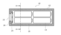
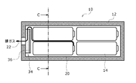
- FIG. 1 is a diagram showing an overall configuration of a battery pack 10 which is an example of an embodiment.
- the battery pack 10 has a box-shaped case 12, and a plurality of, in this example, four batteries 14 are housed in the case 12.
- the battery 14 is a secondary battery, and a non-aqueous electrolyte secondary battery such as a lithium ion battery is used.
- the battery 14 has, for example, a cylindrical shape, and has a positive electrode and a negative electrode at both ends thereof.
- the battery 14 may have an electrode group including a positive electrode and a negative electrode, an outer can that accommodates the electrode group together with an electrolyte, and an opening of the outer can sealed with a sealing plate together with an insulating gasket.
- the outer can may be electrically connected to one of the positive electrode and the negative electrode of the electrode group, and the conductive sealing plate may be connected to the other electrode of the positive electrode and the negative electrode.
- the battery 14 has a square shape, and the positive electrode terminal and the negative electrode terminal may protrude from a common surface of the battery. Further, even if it is cylindrical, the positive electrode and the negative electrode may be collected by a current collecting member on the same end side. A current collecting member such as a metal plate may be connected to the positive electrode and the negative electrode of the battery 14, and the case 12 may be provided with all terminals of the positive electrode and the negative electrode. However, illustration of these electrical connection members will be omitted.
- the battery pack 10 is used as a power source for various electric devices, and may be a large-capacity battery pack for a large device such as a car or a server, or a small-capacity battery pack for a small portable device.
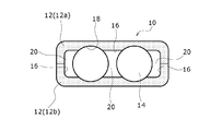
- FIG. 2 is a cross-sectional view of the battery pack 10 (AA cross section in FIG. 1).
- the case 12 has an accommodating portion 18 corresponding to the size of the battery 14 in the internal space of the outer wall 16 formed on the peripheral edge, and the battery 14 is accommodated therein.
- an exhaust gas passage 20 which is an example of an exhaust unit is formed between each of the accommodating portions 18 and the outer wall 16, and a high-temperature gas ejected from the battery 14 flows through the exhaust gas passage 20 when an abnormality occurs.
- a safety valve is provided at the top of the battery 14, and high temperature gas is discharged from the safety valve when the battery is abnormal.
- the case 12 is divided into two half cases 12a and 12b in the height direction, and the entire battery 14 can be covered by superimposing the half cases 12a and 12b in a state of facing each other. Further, in the half cases 12a and 12b, only the tips of the outer walls 16 formed on the peripheral edges of the half cases 12a and 12b are in contact with each other, and the tips of the other parts other than the outer walls 16 are opposed to each other at intervals. This space becomes the exhaust gas passage 20.
- the half cases 12a and 12b may be configured to abut or engage with each other at a portion other than the outer wall 16.
- the exhaust gas passage is not essential in the battery pack 10 of the present disclosure.
- an exhaust port 22 which is an example of an exhaust portion is formed on one side wall of the case 12, and a heat exchanger 24 formed of a porous material having a three-dimensional network structure serves the exhaust port 22 in front of the exhaust port 22. It is arranged to block. In the battery pack 10 of the present disclosure, it is not essential that the heat exchanger is arranged at the exhaust port. When a duct portion that serves as a gas flow path such as the exhaust gas passage is provided, a heat exchanger may be installed in the duct portion.
- the high-temperature gas when the high-temperature gas is discharged from any of the batteries 14 of the battery pack 10, the high-temperature gas flows through the exhaust gas passage 20 and passes through the heat exchanger 24 to lower the temperature, and then the exhaust port 22. Is discharged to the outside.
- an exhaust portion (safety valve) for high-temperature gas is provided at the top of the battery 14 (near the positive electrode terminal), and the exhaust port 22 is provided on the outer wall 16 on the bottom (negative electrode) side of the four batteries 14. ing. Therefore, the high-temperature gas discharged from the battery 14 may be cooled by mixing with the air flowing through the exhaust gas passage 20.
- the exhaust portion may be formed at the bottom of the battery 14 instead of the top.
- the heat exchanger 24 is made of a porous material having a three-dimensional network structure, and from the viewpoint of heat resistance and the like, for example, a porous metal body having three-dimensional continuous pores can be used.
- a porous metal body having three-dimensional continuous pores can be used.
- it is a porous metal body of nickel, aluminum, copper, tin, nichrome, or an alloy selected from a plurality of kinds of these metals.
- a linear skeleton group of metal is branched and extended in a three-dimensional manner.
- a plurality of linear skeletons are connected in a predetermined plane, and a window portion which is an opening defined by these skeletons is connected (or integrated) with these plurality of window portions to surround them three-dimensionally. It has a cavity portion which is a cavity formed by.
- the ease of movement when the gas moves between the adjacent chambers depends on the hole diameter of the opening.
- the average pore diameter of the window portion of the porous metal body used for the heat exchanger may be 0.2 to 2.0 mm.
- the specific surface area may be 250 to 5800 m 2 / m 3 .
- the shape of the heat exchanger is not particularly limited.
- the heat exchanger may be a sheet having a predetermined thickness or a block.
- the thickness (based on the balance) is, for example, 1 to 10 mm.
- the porous material having the three-dimensional network structure may be a sintered body of metal particles, a woven fabric or a non-woven fabric composed of glass fibers. If the temperature of the gas passing through the porous material is not so high, a foam of a thermosetting resin such as urethane may be used.
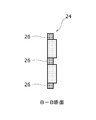
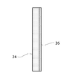
- FIG. 3A is a plan view showing the configuration of the sheet-shaped heat exchanger 24, and FIG. 3B is a cross-sectional view of the heat exchanger 24 based on the BB cutting line in FIG. 3A.
- a high-density portion 26 is formed on the peripheral edge of the main surface of the sheet-shaped heat exchanger 24 over the entire circumference of the peripheral edge. This can be done, for example, by compression molding a porous metal body having a three-dimensional network structure by press working. That is, by partially pressing the mold of the predetermined pattern against the porous body to be the heat exchanger 24, the dimension (thickness) of the porous body is reduced from the rest of the porous body to which the mold is not pressed. ..
- the high-density portion 26 is formed, and since the voids in this portion are smaller than those in the remaining portion, the density of the material (metal) is increased and the rigidity is improved.
- the direction in which the heat exchanger is compressed is not particularly limited.
- the direction in which the gas inflow surface and the gas out surface face each other may be the compression direction.
- the heat exchanger 24 when the heat exchanger 24 is attached so as to close the exhaust port of the case 12, the heat exchanger 24 may be compressed in a direction perpendicular to the surface facing the outside of the case 12.
- the heat exchanger when the heat exchanger is provided in a duct portion such as an exhaust gas passage portion, the heat exchanger may be compressed in the direction in which the passage extends.
- a metal porous body having a three-dimensional network structure more specifically, a foamed metal, it is easy to crush the pores and increase the density by compression molding a part of the porous body.
- the heat exchanger 24 it is possible to suppress an increase in the space required for attaching the heat exchanger to the case 12, and to realize a member strength capable of reducing the reinforcing member supporting the heat exchanger. Then, by fixing the heat exchanger 24 to the case 12 using the high-density portion 26 on the peripheral edge, the deformation of the heat exchanger is suppressed and the attachment becomes easy.
- the remaining portion excluding the high-density portion 26 serves as a flow path through which the high-temperature gas passes.
- the high-density portion 26 at the peripheral edge may be compressed from the periphery to increase the density.
- the density may be twice or more that of the other portions, and depending on the original porosity, compression may be performed by about five times.
- the boundary portion between the high-density portion 26 and the remaining portion may be stepped or inclined. Further, the boundary portion may be formed on only one surface or both sides of both end surfaces in the compression direction.
- the high-density portion 26 is formed so as to extend in a cross shape not only on the peripheral edge but also on the inner side of the main surface of the heat exchanger 24.
- the internal high-density portion 26 can be formed by various patterns, for example, a pattern extending so as to connect the square corners.
- the high-density portion 26 located inward from the peripheral edge may be formed so as to connect the two sides of the opposing peripheral edges, whereby the strength of the heat exchanger 24 as a whole can be improved.
- the high-density portion 26 does not necessarily have to be formed on the peripheral edge, and may be formed only on the inner side of the peripheral edge.
- the shapes of the surface on which the high temperature gas flows in and the surface on which the high temperature gas flows out are not limited to the quadrangle. It may be triangular, hexagonal, circular, oval or elliptical.
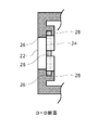
- FIG. 4A is a plan view showing an example of a configuration in which the heat exchanger 24 is fixed to the case 12, and FIG. 4B is a cross-sectional view of the heat exchanger 24 and the case 12 based on the BB cutting line in FIG. 4A. ..
- a claw 28 protruding from the inner surface around the exhaust port 22 of the case 12 is provided. After projecting from the inner surface of the case 12, the claw 28 extends inward and is in contact with the high-density portion 26 (or covers the high-density portion 26). Therefore, the heat exchanger can be fixed to the case 12 by locking the high-density portion 26 on the peripheral edge of the heat exchanger 24 with the portion extending inward.
- the heat exchanger 24 is inserted into the claws 28 of the half cases 12a and 12b of one case 12, and then the half cases 12a and 12b of the other case 12 are inserted.
- the heat exchanger 24 can be fixed by inserting it into the claw 28.
- Various known means can be used to fix the heat exchanger 24.
- the effect of increasing the rigidity of the heat exchanger can be obtained even if the portion other than the high-density portion 26 is held.
- the claws provided on the case 12 may cover the entire circumference of the peripheral edge of the heat exchanger, or may partially cover the peripheral edge of the heat exchanger.
- the heat exchanger of the present disclosure has a predetermined rigidity without being reinforced by a reinforcing member.
- a reinforcing member may be used for the heat exchanger.
- the exhaust port 22 of the case 12 may be a through hole provided in advance, or may be a fragile portion formed so as to be preferentially opened when gas is generated in the battery pack 10. Further, it may be a place where the gas confirmed by an experiment or the like is easily released to the outside, which is not formed intentionally.
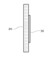
- FIG. 5 is a diagram showing the overall configuration of the battery pack 10, which is another example of the embodiment.
- FIG. 6A is a plan view of another example of the heat exchanger 34
- FIG. 6B is a cross-sectional view of the heat exchanger 34 based on the cutting line CC of FIG. 6A.
- a shielding portion 36 that closes the hole is formed on the surface (inner surface) of the case 12 facing the internal space.
- the shielding portion 36 is provided on the inner surface of the inner surface located at the end of the porous material in the direction of the smaller dimension, the flow path can be regulated more effectively.
- the shielding portion 36 is most effective to provide the shielding portion 36 on the inner surface at the end in the direction of the smallest dimension (thickness direction in the case of a sheet) in the porous material, but in the battery pack 10 of the present disclosure, it is most effective. It is not a requirement that the shielding portion 36 is always provided on the inner surface at the end of the porous material in the direction of the smallest dimension. In particular, when the porous material is in the form of a sheet, a shielding portion 36 is formed on the inner surface located at the end in the thickness direction, and the annular inner surface on the outer peripheral edge of the porous material is exposed to the internal space. May be good.
- the heat exchanger 34 may be larger than the opening of the exhaust port 22.
- the holes on the surface opposite to the inner surface on which the shielding portion 36 is formed are shielded by the outer wall 16 of the case 12. Therefore, the gas flowing in the heat exchanger 34 easily flows between the shielding portion 36 and the outer wall 16. Therefore, it is easier to regulate the gas flow.
- the region of the inner surface facing the portion where the shielding portion 36 is not formed is another member (for example, a case). The gas route can be regulated more effectively by blocking the holes with the outer wall and the exhaust gas passage. Further, the same shielding portion 36 as the shielding portion 36 provided on the inner surface may be formed on the opposite surface.
- the heat exchanger 34 may be fixed to the outer wall 16 of the case 12 around the exhaust port 22 with an adhesive or the like.
- various methods such as providing a claw on the outer wall 16 of the case 12 and engaging the claw with the heat exchanger 34 to fix the heat exchanger 34 can be adopted.
- the heat exchanger 34 can be set in one half case and then the other half case can be attached.
- a partition wall (not shown) having a through hole for dividing the exhaust gas passage 20 into a plurality of chambers is further provided in the exhaust gas path, and the partition wall is provided with a partition wall (not shown). Even if the heat exchanger 34 is attached, the same effect as that of the configuration in which the heat exchanger 34 is provided at the exhaust port 22 can be obtained.
- the entire inner surface of the heat exchanger 34 is the shielding portion 36. Therefore, the gas enters from the side surface of the heat exchanger 34 and exits from the portion facing the exhaust port 22. As a result, the flow path inside the heat exchanger 34 becomes long, and heat exchange with the gas is effectively performed.
- the shielding portion 36 is provided with a non-porous film or non-porous plate of a refractory material such as metal foil attached to the surface of the porous material, or a highly heat-resistant paint containing ceramics is applied to close the pores.
- the pores can be filled with a filler, the pores can be crushed by additional processing on the surface of the porous material, and the skeleton portion of the porous material can be melted and solidified again.
- FIG. 7A is a plan view of another example of the heat exchanger 34
- FIG. 7B is a cross-sectional view of the heat exchanger 34 based on the cutting line CC of FIG. 7A.
- a shielding portion 36 is formed on the surface of the heat exchanger 34 at a position facing the exhaust port 22 and a region around the heat exchanger 34. That is, the shielding portion 36 is partially formed on the inner surface.
- the side surface of the heat exchanger 34 not only the side surface of the heat exchanger 34 but also the peripheral portion of the surface can be used as a gas path, and the gas can be suppressed from passing through the heat exchanger 34 in a short path.
- the holes on the opposite surface of the inner surface where the shielding portion 36 of the porous material is partially provided are blocked by the outer wall 16 of the case 12, the partition wall of the exhaust gas passage, the shielding portion 36, or the like. May be.
- the outer wall 16 of the case 12 located on the opposite surface, the partition wall of the exhaust gas passage, or the shielding portion 36 may include a portion overlapping the shielding portion 36 provided on the inner surface. With this configuration, it is easy to bypass the gas flowing in the heat exchanger 34.
- the heat exchanger 34 arranged at the exhaust port 22 has a structure in which at least a part of the surface of the heat exchanger 34 does not allow exhaust gas to pass through. The efficiency of heat exchange of the heat exchanger 34 is improved.
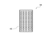
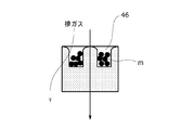
- FIG. 8 is a diagram showing the overall configuration of the battery pack 10, which is another example of the embodiment.
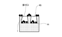
- FIG. 9 is a plan view of the heat exchanger 44. As shown in FIG. 9, a large number of recesses 46 are formed on the surface of the case 12 on the internal space side for accommodating ejecta, and the surface is uneven. As shown in FIG. 8, the heat exchanger 44 is arranged so that the surface on which the recess 46 is formed faces the inside of the case 12. The heat exchanger 44 is larger than the exhaust port 22, and the peripheral portion of the heat exchanger 44 may be fixed to the case 12 around the exhaust port 22 with an adhesive or the like.
- the recess 46 has an inlet opening size of 1 mm or more and a depth of 1 mm or more. Some ejecta have a length of several mm, but there is no problem even if they do not enter the recess 46.
- the ratio of the opening area of the recess 46 to the area of the inner surface is preferably about 10 to 50%, and is preferably evenly distributed at equal intervals. If it is 10% or less, it increases, and if it is 50% or more, the gas passage distance of the heat exchanger 44 as a whole tends to be small.
- the bottom portion of the recess 46 must be thickened so that the heat exchanger 44 can sufficiently cool.
- FIG. 10A is a cross-sectional view showing an example of the shape of the recess 46 by partially excerpting it.
- FIG. 4B is a cross-sectional view showing a partial excerpt of a recess 46 that expands toward the back (bottom), and
- FIG. 4C shows a rounded tip of a wall portion (convex portion) between adjacent recesses 46. It is sectional drawing which shows the heat exchanger 44 partially.
- the shape of the recess 46 is a square cylinder, it may be a cylinder or a polygonal cylinder other than a square.
- the recess 46 can be formed by, for example, compression molding by press working.
- the recess 46 can be formed by pressing a predetermined mold from the surface side of the heat exchanger 44. Further, the pores can be maintained by pushing in to the extent that the recess 46 is formed. Further, the recess 46 may be in the shape of a groove extending on the surface of the heat exchanger 44.
- the ejecta m can be deposited on the bottom of the recess 46 or the non-recessed portion (end surface of the wall portion) on the inner surface, and the side wall of the recess 46 is used as an exhaust gas flow path. It can be used, and it is possible to prevent the surface of the heat exchanger 44 from being blocked by the ejecta m and the pressure loss of the gas from becoming large.
- the bottom surface of the recess 46 is wider than the entrance. Therefore, the narrow opening of the recess 46 makes it easier to reduce the area on the inner surface of the recess 46 where the ejecta m are deposited. On the contrary, on the inner surface of the recess, the area where the ejecta m is hard to accumulate increases.
- the volume of the ejecta m can be suppressed as compared with the portion where the portion that does not overlap the opening of the recess 46 overlaps the opening.
- the gas passage space in the heat exchanger 44 can be maintained.
- Such a recess 46 can be formed by once forming a straight recess 46 such as 10A and then pushing the remaining convex portion from above to spread it laterally or pushing the bottom side of the recess 46 to widen it. can.
- FIG. 10B and FIG. 10C a configuration in which FIG. 10B and FIG. 10C are combined can also be adopted. Further, by providing such a recess 46, the ejected product m can be accommodated in the recess 46, and the exhaust gas can pass through the side surface of the recess 46. Therefore, the surface area of the heat exchanger 44 can be substantially increased so that the gas can pass through efficiently.
Landscapes
- Chemical & Material Sciences (AREA)
- Chemical Kinetics & Catalysis (AREA)
- Electrochemistry (AREA)
- General Chemical & Material Sciences (AREA)
- Engineering & Computer Science (AREA)
- Manufacturing & Machinery (AREA)
- Battery Mounting, Suspending (AREA)
- Gas Exhaust Devices For Batteries (AREA)
Abstract
信頼性を高めることができる電池パック(10)を提供する。電池パック(10)は、ケース(12)の内部に二次電池(14)を収容する。ケース(12)の二次電池(14)を収容する内部空間と外部を連通し、二次電池(14)から排出されたガスを内部空間から外部に排出する排気口(22)と、排気口(22)に設けられ、三次元的網目構造を有する多孔質材で形成されてガスが通過する熱交換体(24)と、を含む。
Description
本開示は、二次電池を収容する電池パックに関する。
リチウムイオン電池などの二次電池は、複数個の電池を電気的に接続してケースに収容した電池パック(電池モジュールともいう)の形態で使用される。この電池パック内の電池に異常があった場合、この電池からは可燃性の高温ガスが発生する。電池は、安全弁を有しており、発生したガスはここから電池パック内部に排出される。電池パックは、排気口につながる排ガスダクトを有しており、ここを介してガスが外部に排出される。ここで、高温の可燃性ガスがそのまま電池パック外に排出されると、問題が生じる場合がある。
特許文献1では、排気口に金属、樹脂などの発泡体(熱交換体)を配置し、排出ガスを通過させることでガスの温度を低下させることが示されている。
ここで、上記熱交換体を用いた電池パックについて更に信頼性を高めることが求められている。
本開示では、信頼性を高めることができる電池パックを提供する。
本開示に係る電池パックは、ケースの内部に二次電池を収容する電池パックであって、ケースの二次電池を収容する内部空間と外部を連通し、二次電池から排出されたガスを内部空間から外部に排出する排気部と、排気部に設けられ、三次元的網目構造を有する多孔質材で形成されてガスが通過する熱交換体と、を含む。
本開示によれば、電池パックとして更に信頼性を高めることができる。
以下、本開示の実施形態について、図面に基づいて説明する。なお、本開示は、ここに記載される実施形態に限定されるものではない。また、以下では全ての図面において同等の要素には同一の符号を付して説明する。また、本文中の説明においては、必要に応じてそれ以前に述べた符号を用いるものとする。
「電池パックの全体構成」
図1は、実施形態の一例である電池パック10の全体構成を示す図である。電池パック10は、箱状のケース12を有し、このケース12内に複数本、この例では4本の電池14が収容されている。電池14は、二次電池であり、例えばリチウムイオン電池などの非水電解質二次電池が用いられる。なお、電池14は、例えば、円筒形であり、その両端に正極と負極をそれぞれ有する。例えば、電池14は正極と負極を含む電極群と、この電極群を電解質とともに収容する外装缶と、この外装缶の開口を絶縁性のガスケットともに封止板が封止していてもよい。このとき外装缶が電極群の正極および負極のうち一方の電極と電気的に接続し、導電性の封口板が正極および負極のうち他方の電極と接続していてもよい。電池14は、角型形状であり、電池の共通の一面から正極端子および負極端子が突出していてもよい。また円筒形であっても、正極と負極とを同じ端部側で集電部材により集電してもよい。電池14の正極および負極には金属板などの集電部材が接続され、ケース12には、正極および負極の総端子が設けられてもよい。しかし、これらの電気的接続部材については図示を省略する。なお、電池パック10は、各種電気機器の電源として利用され、車やサーバーなどの大きな機器用の大容量の電池パックでもよいし、持ち運び可能な小さな機器の小容量の電池パックでもよい。
図1は、実施形態の一例である電池パック10の全体構成を示す図である。電池パック10は、箱状のケース12を有し、このケース12内に複数本、この例では4本の電池14が収容されている。電池14は、二次電池であり、例えばリチウムイオン電池などの非水電解質二次電池が用いられる。なお、電池14は、例えば、円筒形であり、その両端に正極と負極をそれぞれ有する。例えば、電池14は正極と負極を含む電極群と、この電極群を電解質とともに収容する外装缶と、この外装缶の開口を絶縁性のガスケットともに封止板が封止していてもよい。このとき外装缶が電極群の正極および負極のうち一方の電極と電気的に接続し、導電性の封口板が正極および負極のうち他方の電極と接続していてもよい。電池14は、角型形状であり、電池の共通の一面から正極端子および負極端子が突出していてもよい。また円筒形であっても、正極と負極とを同じ端部側で集電部材により集電してもよい。電池14の正極および負極には金属板などの集電部材が接続され、ケース12には、正極および負極の総端子が設けられてもよい。しかし、これらの電気的接続部材については図示を省略する。なお、電池パック10は、各種電気機器の電源として利用され、車やサーバーなどの大きな機器用の大容量の電池パックでもよいし、持ち運び可能な小さな機器の小容量の電池パックでもよい。
図2は、電池パック10の断面図(図1におけるA-A断面)である。このように、ケース12は、周縁に形成された外壁16の内部空間に、電池14の大きさに見合った収容部18を有し、ここに電池14が収容される。また、各収容部18間および外壁16との間には、排気部の一例である排ガス通路20が形成されており、ここに異常時に電池14から噴出する高温ガスが流れる。なお、この例では、電池14の頂部に安全弁が設けられており、電池異常時にここから高温ガスが排出される。また、ケース12は、高さ方向に2つの半ケース12a、12bに2分割されており、半ケース12a、12bを対向した状態で重ね合わせることで、電池14の全体を覆うことができる。また、半ケース12a、12bでは、各半ケース12a、12bの周縁に形成された外壁16の先端のみが当接し、外壁16以外の他の部分の先端は間隔をおいて対向しているため、この空間が排ガス通路20になる。なお、半ケース12a、12bは、外壁16以外の部分で互いに当接する構成や係合する構成であってもよい。なお、本開示の電池パック10では排ガス通路は必須ではない。
また、ケース12の一側壁には、排気部の一例である排気口22が形成されており、その手前に三次元的網目構造の多孔質材で形成された熱交換体24が排気口22を閉塞するように配置されている。なお、本開示の電池パック10では、熱交換体は排気口に配置されることは必須ではない。上記排ガス通路のようなガスの流路となるダクト部を有する場合は、ダクト部内に熱交換体を取り付けてもよい。
従って、電池パック10のいずれかの電池14から高温ガスが放出された場合には、その高温ガスは排ガス通路20を流れ、熱交換体24を通過することで温度が低下した後、排気口22から外部に排出される。
なお、この例では、電池14の頂部(正極端子付近)に高温ガスの排気部(安全弁)が設けられており、排気口22は4つの電池14の底部(負極)側の外壁16に設けられている。従って、電池14から排出された高温ガスは、排ガス通路20を流れる空気との混合による冷却が行われていてもよい。なお、電池14の頂部ではなく底部に排気部が形成されていてもよい。
「熱交換体」
熱交換体24は、三次元的網目構造の多孔質材で形成されており、特に耐熱性などの観点から、例えば三次元的な連続気孔を有する多孔質金属体を用いることができる。例えば、ニッケル、アルミニウム、銅、錫、ニクロムや、これら金属から複数種選ばれた合金の多孔質金属体である。なおこのような多孔質金属体は、金属の線状の骨格群が3次元状に分岐して延びている。この骨格において、所定の平面において複数の線状の骨格が接続するとともにこれら骨格により画定された開口である窓部と、これら複数の窓部が接続し(または一体化し)、立体的に囲うことにより形成された空洞である空洞部とを有する。このとき隣接する室部間のガスが移動する際の移動し易さは開口部の孔径に依存する。このとき熱交換体に用いられる多孔質金属体の窓部の平均孔径は0.2~2.0mmであってもよい。このとき比表面積は250~5800m2/m3であってもよい。なお、熱交換体の形状は特に限定されない。例えば、熱交換体は、所定の厚みを有したシートであってもよく、ブロックであってもよい。熱交換体がシートである場合、厚さ(残部基準)は、例えば1~10mmである。また、上記三次元的網目構造の多孔質材には、金属粒子の焼結体や、ガラス繊維から構成される織布または不織布であってもよい。また、多孔質材を通過するガスの温度があまり高くない場合は、ウレタンなどの熱硬化性樹脂の発泡体などでもよい。
熱交換体24は、三次元的網目構造の多孔質材で形成されており、特に耐熱性などの観点から、例えば三次元的な連続気孔を有する多孔質金属体を用いることができる。例えば、ニッケル、アルミニウム、銅、錫、ニクロムや、これら金属から複数種選ばれた合金の多孔質金属体である。なおこのような多孔質金属体は、金属の線状の骨格群が3次元状に分岐して延びている。この骨格において、所定の平面において複数の線状の骨格が接続するとともにこれら骨格により画定された開口である窓部と、これら複数の窓部が接続し(または一体化し)、立体的に囲うことにより形成された空洞である空洞部とを有する。このとき隣接する室部間のガスが移動する際の移動し易さは開口部の孔径に依存する。このとき熱交換体に用いられる多孔質金属体の窓部の平均孔径は0.2~2.0mmであってもよい。このとき比表面積は250~5800m2/m3であってもよい。なお、熱交換体の形状は特に限定されない。例えば、熱交換体は、所定の厚みを有したシートであってもよく、ブロックであってもよい。熱交換体がシートである場合、厚さ(残部基準)は、例えば1~10mmである。また、上記三次元的網目構造の多孔質材には、金属粒子の焼結体や、ガラス繊維から構成される織布または不織布であってもよい。また、多孔質材を通過するガスの温度があまり高くない場合は、ウレタンなどの熱硬化性樹脂の発泡体などでもよい。
図3Aは、シート状である熱交換体24の構成を示す平面図であり、図3Bは図3AにおけるB-B切断線に基づく熱交換体24の断面図である。図3A、図3Bのように、シート状である熱交換体24の主面の周縁部には、その周縁全周に渡って高密度部26が形成されている。これは、例えば、三次元的網目構造を有する多孔質金属体をプレス加工により圧縮成型することによって行うことができる。すなわち、所定パターンの型を熱交換体24となる上記多孔質体に部分的に押し付けることで、上記多孔質体の寸法(厚み)を型が押し付けられていない上記多孔質体の残部より減少させる。これによって、高密度部26が形成され、この部分は上記残部より空隙が減るため素材(金属)の密度が大きくなり、剛性が向上する。なお、熱交換体を圧縮する方向は、特に限定されない。例えば、ケース12と当接する面に垂直な方向であれば特に限定されない熱交換体24において、ガスの流入する面とガスが出ていく面が向かい合う方向が圧縮する方向であってもよい。例えば、熱交換体24がケース12の排気口を塞ぐように取り付けられる場合は、熱交換体24がケース12の外部と向かい合う面と垂直な方向に熱交換体を圧縮してもよい。また、排ガス通路部などのダクト部内に設けられる場合は通路が延びる方向に熱交換体を圧縮してもよい。三次元的網目構造を有する金属製の多孔質体、より具体的には発泡金属においては、その一部を圧縮成型することで気孔を潰して密度を高めることが容易である。上記熱交換体24により、ケース12へ熱交換体を取り付けるために必要なスペースの増大を抑制し、また熱交換体を支持する補強部材を低減し得る部材強度を実現することができる。そして、周縁の高密度部26を用いて熱交換体24をケース12に固定することで、熱交換体の変形が抑制されて、取り付けが容易になる。また、熱交換体24において、高密度部26を除く残部が、高温ガスが通る流路となる。なお、周縁部の高密度部26については、周辺から圧縮して密度を高めてもよい。高密度部26においては、密度が他の部分の2倍以上であってもよく、もともとの空隙率によるが、5倍程度の圧縮をしてもよい。また、高密度部26と残部との境界部分は段状になっていてもよく傾斜していてもよい。また、この境界部分は、圧縮方向の両端面のうち、一方の面のみでもよく両面に形成されていてもよい。
図3A、図3Bでは、高密度部26は、周縁だけでなく、熱交換体24の主面のうち内方にも十字状に延びて形成されている。内部の高密度部26は、各種のパターンで形成することができ、例えば四角形状の角同士を結ぶように延びるパターンにもできる。周縁より内方にある高密度部26は、対向する周縁の2辺を接続するように形成してもよく、これによって熱交換体24の全体としての強度を向上できる。なお、高密度部26は必ずしも周縁に形成されている必要はなく、周縁より内方のみに形成されていてもよい。また熱交換体において、高温ガスが流入する面および流出する面(シート状の熱交換体では主面)の形状は、四角形に限定されない。三角形、六角形、円形、長円形、楕円形であってもよい。
図4Aは熱交換体24のケース12への固定の構成の一例を示す平面図であり、図4Bは図4AにおけるB-B切断線に基づく同熱交換体24とケース12の断面図である。図4A、図4Bでは、ケース12の排気口22の周辺の内面から突出した爪28を設けている。この爪28は、ケース12の内面から突出した後、内側に向けて延びて高密度部26と当接している(又は高密度部26を覆う)。したがって、内側に伸びた部分により熱交換体24の周縁の高密度部26を係止することでケース12へ熱交換体を固定することができる。特に、この例では、ケース12が2分割されているので、熱交換体24を一方のケース12の半ケース12a、12bの爪28内に挿入し、その後他のケース12の半ケース12a、12bの爪28内に熱交換体24を挿入するようにして固定することができる。なお、熱交換体24の固定するのには公知の各種手段が採用できる。熱交換体24をケース12内に保持する際に高密度部26を保持することにより、ケース12などの保持部材側の一部を熱交換体において窪んでいる高密度部26に収容できる。そのため、ケース12内において熱交換体24の保持に要するスペースが削減できる。なお、本開示の電池パック10では、熱交換体24を保持する場合、高密度部26以外の部分を保持しても熱交換体の剛性を高めるという効果は得られる。また、ケース12に設けた爪は熱交換体の周縁の全周を覆ってもよく、熱交換体の周縁を部分的に覆ってもよい。
このように、発泡金属体で構成されて熱交換体24の一部の剛性を高めることで、厚みの増大や、補強部材の追加無くパック内圧力への耐性と効率的な熱交換の両立を実現できる。なお、本開示の熱交換体は補強部材で補強しなくても所定の剛性を有する。しかしながら、本開示の電池パック10においては熱交換体に補強部材を用いてよいことは言うまでもない。
なお、ケース12の排気口22は、予め設けられた貫通孔でもよいし、電池パック10内でガスが発生した際に優先的に開放するように形成された脆弱部でもよい。また、意図して形成したものではなく、実験等により確認されたガスが外部に放出されやすい箇所でもよい。
図5は、実施形態の他の一例である電池パック10の全体構成を示す図である。図6Aは、熱交換体34の他の一例の平面図であり、図6Bは図6Aの切断線C-Cに基づく熱交換体34の断面図である。このように、ケース12の内部空間に面した表面(内側表面)に孔を閉じる遮蔽部36が形成されている。このとき遮蔽部36は、内側表面のうち、多孔質材においてより寸法が小さい方向の端に位置する内側表面に設けられていると、流路をより効果的に規制することができる。そのため、多孔質材において最も寸法が小さい方向(シート状であれば厚さ方向)の端にある内側表面に遮蔽部36を設けることが最も効果的であるが、本開示の電池パック10では、遮蔽部36が多孔質材において上記最も寸法が小さい方向の端にある内側表面に必ず設けることを要件とはしない。特に多孔質材がシート状である場合は、厚さ方向の端に位置する内側表面に遮蔽部36を形成し、上記多孔質材の外周縁にある環状の内側表面が内部空間に露出してもよい。熱交換体34は、排気口22の開口より大きくなっていてもよい。この構成により、熱交換体34は遮蔽部36が形成された内側表面と反対側の面の孔がケース12の外壁16により遮蔽される。そのため、熱交換体34内を流れるガスは、遮蔽部36と外壁16との間を流れやすくなる。そのため、ガスの流れをより規制し易い。このように熱交換体34の遮蔽部36が形成された内側表面の反対側の面において、上記内側表面のうち遮蔽部36が形成されていない部分と対向する領域は、別の部材(例えばケースの外壁や排ガス通路)などによって孔が塞がれていることでより効果的にガスの経路を規制することができる。また、上記反対側の面にも内側表面に設けられた遮蔽部36と同じ遮蔽部36を形成してもよい。熱交換体34が排気口22の周辺のケース12の外壁16などに接着剤などで固定されていてもよい。なお、熱交換体34のケース12への固定は、ケース12の外壁16に爪を設け、この爪を熱交換体34に係合させて固定するなど各種の方法を採用することができる。特に、この例では、ケース12が半ケース12a、12bに2分割されているので、一方の半ケースに熱交換体34をセットした後、他方の半ケースを取り付けることもできる。なお、熱交換体34が排ガス通路20に配置される場合は、排ガス通路20を複数の室に区切る、貫通孔を有した仕切り壁(図示なし)を排ガス経路内にさらに設け、この仕切り壁に熱交換体34を取り付けても、排気口22に熱交換体34を設ける構成と同様の効果が得られる。
図6A、図6Bでは、熱交換体34の内側表面の全面が遮蔽部36になっている。従って、ガスは、熱交換体34の側面から入り、排気口22に面している部分から外部に出る。これによって、熱交換体34内部の流路が長くなり、ガスとの熱交換が効果的に行われる。
なお、遮蔽部36は、多孔質材の表面に金属箔などの高融点材料の無孔膜や無孔板を張り付けたり、セラミックスを含むような高耐熱性の塗料を塗布して孔を塞いだり、充填材を孔に充填したり、多孔質材の表面の追加工により気孔を潰したり、多孔質材の骨格部分を溶融させて再度凝固させるなどの手法により形成することができる。
図7Aは、熱交換体34の他の例の平面図であり、図7Bは図7Aの切断線C-Cに基づく熱交換体34の断面図である。図7A、図7Bでは熱交換体34の表面において、排気口22に対向する位置およびその周辺の領域に遮蔽部36が形成されている。つまり、この内側表面において部分的に遮蔽部36が形成されている。この構成では、熱交換体34の側面だけでなく、表面の周辺部分もガスの経路として用いることができ、かつ短い経路で熱交換体34をガスが通過することを抑制できる。ここでも、多孔質材の遮蔽部36が部分的に設けられた内側表面の反対側の面の孔がケース12の外壁16、排ガス通路の仕切り壁、あるいは遮蔽部36などにより遮られることで塞がっていてもよい。このとき上記反対側の面に位置するケース12の外壁16、排ガス通路の仕切り壁、あるいは遮蔽部36は、内側表面に設けられた遮蔽部36と重なる部分を備えていてもよい。この構成により、熱交換体34内を流れるガスを迂回させやすい。
このように、本開示に係る電池パック10では、排気口22に配置された熱交換体34において、熱交換体34の表面の少なくとも一部が、排ガスが通過できない構造になっていることで、熱交換体34の熱交換の効率を高めている。
従って、高温ガスが多孔質材内を通過する際のより短い経路の入り口となる多孔質材の表面への侵入することを抑制することで、多孔質材を著しく大型化することなく熱交換のためのより長い接触経路を形成することができる。このため、電池パック10の体積エネルギー密度が低下、または部材コストが増大することなく高安全な電池パック10を提供することができる。
図8は、実施形態の他の一例である電池パック10の全体構成を示す図である。図9は、熱交換体44の平面図である。図9のように、ケース12の内部空間側の表面に噴出物収容のために多数の凹部46が形成されており、表面が凸凹になっている。図8に示すように、熱交換体44は、凹部46が形成された表面をケース12の内部に向けて配置される。熱交換体44は、排気口22より大きくなっており、熱交換体44の周辺部分を排気口22の周辺のケース12に接着剤などで固定するとよい。なお、熱交換体44のケース12への固定は、ケース12側に爪を設け、この爪を熱交換体44に係合させて固定するなど各種の方法を採用することができる。特に、この例では、ケース12が2分割されているので、ケース12を分割した状態で熱交換体44を固定することもできる。
ここで、ガスに含まれる噴出物としては、数100μm程度のものが多い、そこで凹部46は、入口開口の大きさが1mm以上、深さが1mm以上であるとよい。なお、噴出物には、数mmに及ぶものもあるが、これは凹部46に入らなくても問題ない。
内部空間側から見て、内側表面の面積に対する凹部46の開口面積の比率は、10~50%程度であるとよく、等間隔で均一に分布していることが好ましい。10%以下であると、増加する、50%以上であると、熱交換体44全体としてのガス通過距離が小さくなりやすい。この熱交換体44で十分に冷却できるよう凹部46の底の部分を厚くしなければならなくなる。
図10Aは、凹部46の形状の一例を部分的に抜粋して示した断面図である。図4Bは奥(底)に行くほど広がる凹部46を部分的に抜粋して示した断面図であり、図4Cは隣り合う凹部46の間にある壁部(凸部)の先端が丸く面取りされている熱交換体44を部分的に示す断面図である。なお、凹部46の形状は、四角筒状のものを示したが、円筒状でも、四角以外の多角筒状でもよい。また、凹部46は、例えばプレス加工による圧縮成型によって形成することができる。熱交換体44の表面側から所定の型を押し付けることによって、凹部46を形成できる。また、凹部46を形成する程度の押し込みでは、気孔を維持することができる。また凹部46は、熱交換体44の表面を延びる溝の形状であってもよい。
図10Aに示すように、凹部46を形成することによって、噴出物mを凹部46の底や内側表面の凹部未形成部分(壁部の端面)に堆積でき、凹部46の側壁を排ガス流路として利用することができ、噴出物mで熱交換体44の表面が閉塞してガスの圧損が大きくなってしまうことを抑制することができる。
図10Bでは、凹部46の底面が入口より広い。従って、凹部46の狭い開口により、凹部46の内面のうちで噴出物mが堆積する領域を減らしやすくなる。反対に凹部の内面のうち、噴出物mが堆積しにくい領域が増える。図10Aの凹部46と比べて図10Bの凹部46の底において、凹部46の開口と重ならない部分が開口と重なる部分と比べて噴出物mの体積が抑制され得る。熱交換体44におけるガスの通過スペースを維持できる。このような凹部46は、一旦10Aのようなストレートな凹部46を形成した後、残った凸部を上から押して横に広げたり、凹部46の底部側を押し広げたりすることで形成することができる。
図10Cでは、凹部46間の凸部の先端(端面)を丸く面取りすることで、面取りされた部分に付着した噴出物mは面取りした部分にとどまらず、凹部46の底部にむかって移動する。そして、噴出物mが凸部の端面上に堆積し難い。そのため、この端面における孔は噴出物mにより目詰まりしにくくなり、表面での排ガス通過を効果的に行える。なお、凸部を面取りする場合、傾斜面を形成して面取りをしてもよい。
なお、図10Bと図10Cを組み合わせた構成を採用することもできる。また、このような凹部46を設けることで、噴出物mを凹部46に収容できるとともに、凹部46の側面を排ガスが通過できる。従って、熱交換体44の表面積を実質的に大きくして、ガスの通過を効率的に行える。
このように、凹部46を設けることで、噴出物mによる熱交換体44の目詰まりを抑制できる。そのため、目詰まりによるガスの圧損を抑制できる。従って、冷却効率の高い微細な構造の熱交換部材を使用することができる。このため、熱交換体44の体積をあまり大きくする必要がなく、電池パック10の体積エネルギー密度を低下、または部材コストを増大させることなく安全な電池パック10を提供することができる。
10 電池パック、12 ケース、12a、12b 半ケース、14 電池、16 外
壁、18 収容部、20 排ガス通路、22 排気口、24 熱交換体、26 高密度部
、28 爪、34 熱交換体、36 遮蔽部、44 熱交換体、46 凹部、m 噴出物
壁、18 収容部、20 排ガス通路、22 排気口、24 熱交換体、26 高密度部
、28 爪、34 熱交換体、36 遮蔽部、44 熱交換体、46 凹部、m 噴出物
Claims (22)
- ケースの内部に二次電池を収容する電池パックであって、
前記ケースの前記二次電池を収容する内部空間と外部を連通し、前記二次電池から排出されたガスを前記内部空間から外部に排出する排気部と、
前記排気部に設けられ、三次元的網目構造を有する多孔質材で形成されて前記ガスが通過する熱交換体と、
を含む、電池パック。 - 所定の方向を第1方向とし、前記熱交換体は、前記第1方向における寸法が残部より小さく、前記残部より密度が高い高密度部を有し、
前記高密度部が前記ケースに固定された、
請求項1に記載の電池パック。 - 前記排気部は、前記ケースの外部に向けて開口した排気口を有し、
前記熱交換体は、前記排気口を塞ぐように前記ケースに固定された、
請求項2に記載の電池パック。 - 前記排気部は、前記ケースの外部に向けて開口した排気口と、前記排気口と前記内部空間とを接続するダクト部とを有し、
前記熱交換体は、前記ダクト部を塞ぐように前記ケースに固定された、
請求項2に記載の電池パック。 - 前記高密度部は、前記第1方向における一対の端面における周縁に設けられた、
請求項2に記載の電池パック。 - 前記高密度部は、前記熱交換体の周縁全周に設けられる、
請求項2に記載の電池パック。 - 前記高密度部は、前記熱交換体の前記第1方向の端面において、周縁より内方に設けられた、
請求項2に記載の電池パック。 - 前記高密度部は、前記熱交換体の周縁全周に設けられるとともに、周縁の前記高密度部に両端が接続される内部の前記高密度部をさらに有する、
請求項2に記載の電池パック。 - 前記ケースは、前記高密度部の前記第1方向の端面を覆う、
請求項2に記載の電池パック。 - 前記熱交換体は、前記多孔質材の前記内部空間に面した内側表面における孔を塞ぐ遮蔽部を有する、
請求項1に記載の電池パック。 - 前記遮蔽部は、前記内側表面の前記排気部に対向する位置に形成される、
請求項10に記載の電池パック。 - 前記遮蔽部は、前記多孔質材の表面を覆う無孔板である、
請求項10に記載の電池パック。 - 前記遮蔽部は、前記多孔質材の孔内に収容された充填材である、
請求項10に記載の電池パック。 - 前記遮蔽部は、前記多孔質材における前記三次元的網目構造を構成する骨格同士が接合して形成された、
請求項10に記載の電池パック。 - 前記多孔質材は、前記遮蔽部が設けられた表面の反対側にある面の孔が塞がれた、
請求項10に記載の電池パック。 - 前記多孔質材は、シート状であり、
前記遮蔽部は、前記多孔質材の厚さ方向の一端にある表面に形成された、
請求項10に記載の電池パック。 - 前記多孔質材において、前記遮蔽部が形成された表面の反対側の面の孔が塞がれた領域を有し、前記孔が塞がれた領域の少なくとも一部が前記遮蔽部と重なる、
請求項10に記載の電池パック。 - 前記熱交換体における前記内部空間と面した表面に少なくとも一つの凹部が形成されている、
請求項1に記載の電池パック。 - 少なくとも一つの前記凹部は、開口の大きさが1mm以上、深さが1mm以上である、
請求項18に記載の電池パック。 - 前記表面を前記内部空間側から見て、前記表面の面積に対する少なくとも一つの前記凹部の面積の比率は、10~50%である、
請求項18または19に記載の電池パック。 - 少なくとも一つの前記凹部の底部は、前記凹部の入口より広い、
請求項18~20のいずれか1つに記載の電池パック。 - 少なくとも一つの前記凹部のうち、前記凹部と前記凹部との間に存在する壁部の先端は面取りされている、
請求項18~20のいずれか1つに記載の電池パック。
Priority Applications (4)
| Application Number | Priority Date | Filing Date | Title |
|---|---|---|---|
| EP21779543.4A EP4131576A1 (en) | 2020-03-31 | 2021-03-30 | Battery pack |
| US17/914,186 US20230207955A1 (en) | 2020-03-31 | 2021-03-30 | Battery pack |
| JP2022512535A JPWO2021200941A1 (ja) | 2020-03-31 | 2021-03-30 | |
| CN202180023145.1A CN115336095A (zh) | 2020-03-31 | 2021-03-30 | 电池组 |
Applications Claiming Priority (6)
| Application Number | Priority Date | Filing Date | Title |
|---|---|---|---|
| JP2020-063657 | 2020-03-31 | ||
| JP2020-063647 | 2020-03-31 | ||
| JP2020-063666 | 2020-03-31 | ||
| JP2020063647 | 2020-03-31 | ||
| JP2020063666 | 2020-03-31 | ||
| JP2020063657 | 2020-03-31 |
Publications (1)
| Publication Number | Publication Date |
|---|---|
| WO2021200941A1 true WO2021200941A1 (ja) | 2021-10-07 |
Family
ID=77928487
Family Applications (1)
| Application Number | Title | Priority Date | Filing Date |
|---|---|---|---|
| PCT/JP2021/013529 WO2021200941A1 (ja) | 2020-03-31 | 2021-03-30 | 電池パック |
Country Status (5)
| Country | Link |
|---|---|
| US (1) | US20230207955A1 (ja) |
| EP (1) | EP4131576A1 (ja) |
| JP (1) | JPWO2021200941A1 (ja) |
| CN (1) | CN115336095A (ja) |
| WO (1) | WO2021200941A1 (ja) |
Cited By (1)
| Publication number | Priority date | Publication date | Assignee | Title |
|---|---|---|---|---|
| WO2023167467A1 (ko) * | 2022-03-02 | 2023-09-07 | 주식회사 엘지에너지솔루션 | 안전성이 강화된 배터리 모듈 |
Citations (5)
| Publication number | Priority date | Publication date | Assignee | Title |
|---|---|---|---|---|
| JPH03134952A (ja) | 1989-10-19 | 1991-06-07 | Matsushita Electric Ind Co Ltd | パッケージ型電池 |
| JP2009212081A (ja) * | 2008-02-04 | 2009-09-17 | Panasonic Corp | 電池パック、それを備えた電子機器および電池収納部を備えた電子機器 |
| US20120015218A1 (en) * | 2010-07-19 | 2012-01-19 | Hyun-Ye Lee | Battery module |
| JP2014160573A (ja) * | 2013-02-20 | 2014-09-04 | Hochiki Corp | 蓄電装置 |
| WO2015045404A1 (ja) * | 2013-09-30 | 2015-04-02 | パナソニックIpマネジメント株式会社 | 電池ユニット |
-
2021
- 2021-03-30 CN CN202180023145.1A patent/CN115336095A/zh active Pending
- 2021-03-30 JP JP2022512535A patent/JPWO2021200941A1/ja active Pending
- 2021-03-30 EP EP21779543.4A patent/EP4131576A1/en active Pending
- 2021-03-30 WO PCT/JP2021/013529 patent/WO2021200941A1/ja unknown
- 2021-03-30 US US17/914,186 patent/US20230207955A1/en active Pending
Patent Citations (5)
| Publication number | Priority date | Publication date | Assignee | Title |
|---|---|---|---|---|
| JPH03134952A (ja) | 1989-10-19 | 1991-06-07 | Matsushita Electric Ind Co Ltd | パッケージ型電池 |
| JP2009212081A (ja) * | 2008-02-04 | 2009-09-17 | Panasonic Corp | 電池パック、それを備えた電子機器および電池収納部を備えた電子機器 |
| US20120015218A1 (en) * | 2010-07-19 | 2012-01-19 | Hyun-Ye Lee | Battery module |
| JP2014160573A (ja) * | 2013-02-20 | 2014-09-04 | Hochiki Corp | 蓄電装置 |
| WO2015045404A1 (ja) * | 2013-09-30 | 2015-04-02 | パナソニックIpマネジメント株式会社 | 電池ユニット |
Cited By (1)
| Publication number | Priority date | Publication date | Assignee | Title |
|---|---|---|---|---|
| WO2023167467A1 (ko) * | 2022-03-02 | 2023-09-07 | 주식회사 엘지에너지솔루션 | 안전성이 강화된 배터리 모듈 |
Also Published As
| Publication number | Publication date |
|---|---|
| JPWO2021200941A1 (ja) | 2021-10-07 |
| CN115336095A (zh) | 2022-11-11 |
| EP4131576A1 (en) | 2023-02-08 |
| US20230207955A1 (en) | 2023-06-29 |
Similar Documents
| Publication | Publication Date | Title |
|---|---|---|
| CN112331992B (zh) | 电池包及装置 | |
| US10629869B2 (en) | Electronic apparatus case and battery pack including the same | |
| JP6255151B2 (ja) | バッテリパック | |
| JP4243334B2 (ja) | 組電池 | |
| EP3065212B1 (en) | Frame for secondary battery and battery module comprising the same | |
| KR101106111B1 (ko) | 효율적인 냉각 및 배기 구조의 중대형 전지팩 | |
| JP7325063B2 (ja) | 電池モジュール | |
| JP2004213922A (ja) | 角形密閉式二次電池と電池モジュール及び組電池 | |
| JP2009224226A (ja) | 電池モジュールおよびこれを備えたバッテリパック | |
| US20200112009A1 (en) | Electrochemical cell enclosure including a flame arrestor | |
| EP3667764B1 (en) | Battery module | |
| WO2021200941A1 (ja) | 電池パック | |
| CN115602994A (zh) | 电池模组和用电设备 | |
| JP5632402B2 (ja) | フィルム外装電気デバイス集合体 | |
| WO2021024664A1 (ja) | 電池モジュール | |
| CN114144924A (zh) | 碱性二次电池及碱性二次电池模块 | |
| CA3055946A1 (en) | Electrochemical cell enclosure including a flame arrestor | |
| KR101898292B1 (ko) | 전지팩 어셈블리 | |
| JP6684613B2 (ja) | 電池モジュール及び組電池 | |
| CN209786055U (zh) | 一种电池模组 | |
| CN116711133A (zh) | 电池的箱体、电池、用电装置、制备电池的方法和装置 | |
| EP4246665A1 (en) | Battery pack | |
| CN219303904U (zh) | 电池单体及电池和用电装置 | |
| EP4376192A1 (en) | Battery pack and energy storage system comprising same | |
| US20230361420A1 (en) | Battery module |
Legal Events
| Date | Code | Title | Description |
|---|---|---|---|
| 121 | Ep: the epo has been informed by wipo that ep was designated in this application |
Ref document number: 21779543 Country of ref document: EP Kind code of ref document: A1 |
|
| ENP | Entry into the national phase |
Ref document number: 2022512535 Country of ref document: JP Kind code of ref document: A |
|
| NENP | Non-entry into the national phase |
Ref country code: DE |
|
| ENP | Entry into the national phase |
Ref document number: 2021779543 Country of ref document: EP Effective date: 20221031 |