WO2021200445A1 - 蓄電装置の組電池制御回路の電力供給方式、及び蓄電装置 - Google Patents
蓄電装置の組電池制御回路の電力供給方式、及び蓄電装置 Download PDFInfo
- Publication number
- WO2021200445A1 WO2021200445A1 PCT/JP2021/012184 JP2021012184W WO2021200445A1 WO 2021200445 A1 WO2021200445 A1 WO 2021200445A1 JP 2021012184 W JP2021012184 W JP 2021012184W WO 2021200445 A1 WO2021200445 A1 WO 2021200445A1
- Authority
- WO
- WIPO (PCT)
- Prior art keywords
- power
- converter
- battery module
- control circuit
- storage device
- Prior art date
- Legal status (The legal status is an assumption and is not a legal conclusion. Google has not performed a legal analysis and makes no representation as to the accuracy of the status listed.)
- Ceased
Links
Images

Classifications
-
- H—ELECTRICITY
- H01—ELECTRIC ELEMENTS
- H01M—PROCESSES OR MEANS, e.g. BATTERIES, FOR THE DIRECT CONVERSION OF CHEMICAL ENERGY INTO ELECTRICAL ENERGY
- H01M10/00—Secondary cells; Manufacture thereof
- H01M10/42—Methods or arrangements for servicing or maintenance of secondary cells or secondary half-cells
- H01M10/48—Accumulators combined with arrangements for measuring, testing or indicating the condition of cells, e.g. the level or density of the electrolyte
- H01M10/482—Accumulators combined with arrangements for measuring, testing or indicating the condition of cells, e.g. the level or density of the electrolyte for several batteries or cells simultaneously or sequentially
-
- H—ELECTRICITY
- H02—GENERATION; CONVERSION OR DISTRIBUTION OF ELECTRIC POWER
- H02J—ELECTRIC POWER NETWORKS; CIRCUIT ARRANGEMENTS OR SYSTEMS FOR SUPPLYING OR DISTRIBUTING ELECTRIC POWER; SYSTEMS FOR STORING ELECTRIC ENERGY
- H02J7/00—Circuit arrangements for charging or discharging batteries or for supplying loads from batteries
- H02J7/34—Parallel operation in networks using both storage and other DC sources, e.g. providing buffering
-
- H—ELECTRICITY
- H01—ELECTRIC ELEMENTS
- H01M—PROCESSES OR MEANS, e.g. BATTERIES, FOR THE DIRECT CONVERSION OF CHEMICAL ENERGY INTO ELECTRICAL ENERGY
- H01M10/00—Secondary cells; Manufacture thereof
- H01M10/42—Methods or arrangements for servicing or maintenance of secondary cells or secondary half-cells
- H01M10/44—Methods for charging or discharging
- H01M10/441—Methods for charging or discharging for several batteries or cells simultaneously or sequentially
-
- H—ELECTRICITY
- H02—GENERATION; CONVERSION OR DISTRIBUTION OF ELECTRIC POWER
- H02J—ELECTRIC POWER NETWORKS; CIRCUIT ARRANGEMENTS OR SYSTEMS FOR SUPPLYING OR DISTRIBUTING ELECTRIC POWER; SYSTEMS FOR STORING ELECTRIC ENERGY
- H02J7/00—Circuit arrangements for charging or discharging batteries or for supplying loads from batteries
- H02J7/50—Circuit arrangements for charging or discharging batteries or for supplying loads from batteries acting upon multiple batteries simultaneously or sequentially
-
- H—ELECTRICITY
- H02—GENERATION; CONVERSION OR DISTRIBUTION OF ELECTRIC POWER
- H02J—ELECTRIC POWER NETWORKS; CIRCUIT ARRANGEMENTS OR SYSTEMS FOR SUPPLYING OR DISTRIBUTING ELECTRIC POWER; SYSTEMS FOR STORING ELECTRIC ENERGY
- H02J7/00—Circuit arrangements for charging or discharging batteries or for supplying loads from batteries
- H02J7/60—Circuit arrangements for charging or discharging batteries or for supplying loads from batteries including safety or protection arrangements
- H02J7/63—Circuit arrangements for charging or discharging batteries or for supplying loads from batteries including safety or protection arrangements against overdischarge
-
- H—ELECTRICITY
- H02—GENERATION; CONVERSION OR DISTRIBUTION OF ELECTRIC POWER
- H02J—ELECTRIC POWER NETWORKS; CIRCUIT ARRANGEMENTS OR SYSTEMS FOR SUPPLYING OR DISTRIBUTING ELECTRIC POWER; SYSTEMS FOR STORING ELECTRIC ENERGY
- H02J7/00—Circuit arrangements for charging or discharging batteries or for supplying loads from batteries
- H02J7/60—Circuit arrangements for charging or discharging batteries or for supplying loads from batteries including safety or protection arrangements
- H02J7/685—Circuit arrangements for charging or discharging batteries or for supplying loads from batteries including safety or protection arrangements using connection detecting circuits
-
- H—ELECTRICITY
- H02—GENERATION; CONVERSION OR DISTRIBUTION OF ELECTRIC POWER
- H02J—ELECTRIC POWER NETWORKS; CIRCUIT ARRANGEMENTS OR SYSTEMS FOR SUPPLYING OR DISTRIBUTING ELECTRIC POWER; SYSTEMS FOR STORING ELECTRIC ENERGY
- H02J7/00—Circuit arrangements for charging or discharging batteries or for supplying loads from batteries
- H02J7/90—Regulation of charging or discharging current or voltage
-
- H—ELECTRICITY
- H02—GENERATION; CONVERSION OR DISTRIBUTION OF ELECTRIC POWER
- H02J—ELECTRIC POWER NETWORKS; CIRCUIT ARRANGEMENTS OR SYSTEMS FOR SUPPLYING OR DISTRIBUTING ELECTRIC POWER; SYSTEMS FOR STORING ELECTRIC ENERGY
- H02J9/00—Circuit arrangements for emergency or stand-by power supply, e.g. for emergency lighting
- H02J9/04—Circuit arrangements for emergency or stand-by power supply, e.g. for emergency lighting in which the distribution system is disconnected from the normal source and connected to a standby source
- H02J9/06—Circuit arrangements for emergency or stand-by power supply, e.g. for emergency lighting in which the distribution system is disconnected from the normal source and connected to a standby source with automatic change-over, e.g. UPS systems
- H02J9/062—Circuit arrangements for emergency or stand-by power supply, e.g. for emergency lighting in which the distribution system is disconnected from the normal source and connected to a standby source with automatic change-over, e.g. UPS systems for AC powered loads
-
- H—ELECTRICITY
- H02—GENERATION; CONVERSION OR DISTRIBUTION OF ELECTRIC POWER
- H02M—APPARATUS FOR CONVERSION BETWEEN AC AND AC, BETWEEN AC AND DC, OR BETWEEN DC AND DC, AND FOR USE WITH MAINS OR SIMILAR POWER SUPPLY SYSTEMS; CONVERSION OF DC OR AC INPUT POWER INTO SURGE OUTPUT POWER; CONTROL OR REGULATION THEREOF
- H02M3/00—Conversion of DC power input into DC power output
- H02M3/22—Conversion of DC power input into DC power output with intermediate conversion into AC
- H02M3/24—Conversion of DC power input into DC power output with intermediate conversion into AC by static converters
- H02M3/28—Conversion of DC power input into DC power output with intermediate conversion into AC by static converters using discharge tubes with control electrode or semiconductor devices with control electrode to produce the intermediate AC
- H02M3/325—Conversion of DC power input into DC power output with intermediate conversion into AC by static converters using discharge tubes with control electrode or semiconductor devices with control electrode to produce the intermediate AC using devices of a triode or a transistor type requiring continuous application of a control signal
- H02M3/335—Conversion of DC power input into DC power output with intermediate conversion into AC by static converters using discharge tubes with control electrode or semiconductor devices with control electrode to produce the intermediate AC using devices of a triode or a transistor type requiring continuous application of a control signal using semiconductor devices only
- H02M3/33569—Conversion of DC power input into DC power output with intermediate conversion into AC by static converters using discharge tubes with control electrode or semiconductor devices with control electrode to produce the intermediate AC using devices of a triode or a transistor type requiring continuous application of a control signal using semiconductor devices only having several active switching elements
-
- H—ELECTRICITY
- H02—GENERATION; CONVERSION OR DISTRIBUTION OF ELECTRIC POWER
- H02J—ELECTRIC POWER NETWORKS; CIRCUIT ARRANGEMENTS OR SYSTEMS FOR SUPPLYING OR DISTRIBUTING ELECTRIC POWER; SYSTEMS FOR STORING ELECTRIC ENERGY
- H02J2207/00—Details of circuit arrangements for charging or discharging batteries or supplying loads from batteries
- H02J2207/10—Control circuit supply, e.g. means for supplying power to the control circuit
-
- Y—GENERAL TAGGING OF NEW TECHNOLOGICAL DEVELOPMENTS; GENERAL TAGGING OF CROSS-SECTIONAL TECHNOLOGIES SPANNING OVER SEVERAL SECTIONS OF THE IPC; TECHNICAL SUBJECTS COVERED BY FORMER USPC CROSS-REFERENCE ART COLLECTIONS [XRACs] AND DIGESTS
- Y02—TECHNOLOGIES OR APPLICATIONS FOR MITIGATION OR ADAPTATION AGAINST CLIMATE CHANGE
- Y02E—REDUCTION OF GREENHOUSE GAS [GHG] EMISSIONS, RELATED TO ENERGY GENERATION, TRANSMISSION OR DISTRIBUTION
- Y02E60/00—Enabling technologies; Technologies with a potential or indirect contribution to GHG emissions mitigation
- Y02E60/10—Energy storage using batteries
Definitions
- the present invention relates to a power supply method for an assembled battery control circuit of a power conversion device for charging a battery module and a power storage device including the battery module, and a power storage device.
- a power storage device equipped with a battery module has been developed (see Patent Document 1).
- the battery module is provided with a battery control circuit, and a battery module that supplies operating power from the battery of the battery module has also been developed as a DC / DC converter that steps down the battery voltage of the battery module using the power supply circuit of this control circuit. ing.
- This battery module has an adverse effect of consuming power from the battery in order to operate the control circuit. Even when the battery module is not used, that is, when the battery module is not discharged, the control circuit operates at predetermined time intervals and detects the remaining capacity, so that there is an adverse effect of power consumption in this state.
- this power supply circuit supplies operating power from the battery to the control circuit, there is an adverse effect of being discharged by the dark current of the control circuit and over-discharging, and when the battery voltage of the battery module drops, the control circuit is connected. There is a drawback that the supply voltage of the battery drops and it becomes impossible to maintain a normal operating state.
- the present invention has been developed for the purpose of eliminating the above-mentioned drawbacks, and one of the purposes of the present invention is to stably supply operating power to a battery control circuit from both commercial power and a battery module. To provide technology.
- the power supply method of the assembled battery control circuit of the power storage device is a battery module including a plurality of rechargeable battery cells and a built-in battery control circuit, and the battery module is charged with commercial power and commercial power is supplied.
- This is a power supply method for a battery assembly control circuit in a power storage device including a power conversion device for supplying a load.
- the battery assembly control of the battery module is performed from the power conversion device.
- the operating power from the battery module to the assembled battery control circuit is started by the connection signal from the connection detection unit that supplies the operating power to the circuit and detects the state in which the power conversion device starts supplying power to the assembled battery control circuit.
- the power supply from the battery module to the assembled battery control circuit is stopped by the stop signal from the discharge stop determination unit that detects the discharge stop state of the battery module.
- the power storage device includes a power conversion device in which power is supplied from a commercial power source to supply power to a load, a battery module including a plurality of rechargeable battery cells and an assembled battery control circuit, and a power conversion device.
- a switching circuit that switches the supply of power from the battery module to the assembled battery control circuit, a connection detector that detects the power supply from the power converter to the assembled battery control circuit, and a discharge stop determination in the discharge stop state of the battery module. It has a department.
- the switching circuit supplies power from the power converter to the assembled battery control circuit when the output voltage of the power converter is higher than the set voltage, and detects the power supply from the power converter to the assembled battery control circuit.
- the connection signal from the connection detection unit supplies the operating power from the battery module to the assembled battery control circuit, and the discharge stop signal from the discharge stop determination unit stops the power supply from the battery module to the assembled battery control circuit.
- the power storage device includes a power conversion device in which power is supplied from a commercial power source to supply power to a load, a battery module including a plurality of rechargeable battery cells and an assembled battery control circuit, and an assembled battery.
- a DC / DC converter that supplies operating power to the control circuit, a switching circuit that switches the connection between the power converter and the battery module, a connection detector that detects the power supply from the power converter to the assembled battery control circuit, and a battery. It is equipped with a discharge stop determination unit in the discharge stop state of the module.
- the switching circuit is a connection from a connection detection unit that connects the power converter to the DC / DC converter and detects the connection between the power converter and the DC / DC converter when the output voltage of the power converter is higher than the set voltage.
- the battery module is connected to the DC / DC converter by a signal, and the connection between the battery module and the DC / DC converter is cut off by the discharge stop signal from the discharge stop determination unit.
- the above-mentioned power supply method and power storage device of the battery control circuit of the power storage device have a feature that the operating power can be stably supplied to the battery control circuit from both the power conversion device and the battery module.
- the power supply method of the assembled battery control circuit in the power storage device includes a battery module including a plurality of rechargeable battery cells and a built-in battery control circuit, and the battery module is charged with commercial power and is commercially available.
- the operating power from the battery module to the assembled battery control circuit is started by the connection signal from the connection detector that supplies the operating power to the battery control circuit and detects the state in which the power converter starts supplying power to the assembled battery control circuit. Then, the power supply from the battery module to the assembled battery control circuit is stopped by the stop signal from the discharge stop determination unit that detects the discharge stop state of the battery module.
- the power supply method of the assembled battery control circuit in the above power storage device is ideal because the operating power is supplied to the assembled battery control circuit from both the power converter and the battery module, without providing a dedicated power supply for the assembled battery control circuit. It is possible to supply operating power in a normal state. Since the assembled battery control circuit monitors the state of each battery cell, it is held in the operation mode and consumes power even when the battery module is not used, that is, when it is not discharged.
- the power storage device includes a large number of battery cells in order to increase the charge / discharge capacity and output. Since this power storage device manages a large number of battery cells, the power consumption of the assembled battery control circuit becomes large, and the conventional power storage device provides power to the assembled battery control circuit by providing a dedicated power source.
- This power storage device needs to be provided with a dedicated power source, which increases the equipment cost. This adverse effect can be eliminated by adjusting the output voltage of the power converter or the battery module itself with a DC / DC converter and supplying it to the assembled battery control circuit.
- the power storage device that supplies power from the power converter to the battery control circuit can adjust the voltage of the output of the power converter with a DC / DC converter and supply it to the battery control circuit, but the power converter always outputs the voltage. If it is not in the state and the voltage is not output, the operating power cannot be supplied to the assembled battery control circuit.
- the power conversion device outputs a voltage in a state of charging the battery module and in a state of supplying power to the load, but does not output a voltage in a state of not charging the battery module and supplying power to the load. It is possible to adjust the output voltage of the battery module to supply operating power to the assembled battery control circuit, but this power storage device cannot supply operating power to the assembled battery control circuit when the voltage of the battery module drops to the minimum voltage. .. Further, in the device for supplying the operating power from the battery module to the assembled battery control circuit, the battery module constantly consumes the power, and the voltage gradually decreases.
- the operating power is supplied to the assembled battery control circuit from both the power converter and the battery module, and the output voltage of the power converter is higher than the set voltage.
- the connection detector detects that the power converter supplies the operating power to the assembled battery control circuit and further supplies the operating power from the power converter to the assembled battery control circuit, and the battery module also supplies the operating power to the assembled battery control circuit.
- the operating power is supplied to the assembled battery control circuit from both the power converter and the battery module. In this state, when the voltage of the battery module drops or the like causes an over-discharge state, the discharge stop determination unit detects this and stops the power supply from the battery module.
- the battery module does not become over-discharged, and power can be supplied to the assembled battery control circuit. Further, in a state where the battery module is over-discharged, power can be supplied from the power conversion device to the assembled battery control circuit to keep the assembled battery control circuit in the operating state. When the voltage of the battery module drops, the power converter outputs a predetermined voltage to charge the battery module. Therefore, in this state, the output from the power converter can supply the operating power to the assembled battery control circuit. .. Therefore, the power supply method of the assembled battery control circuit in the above power storage device can supply the operating power in an ideal state from both the power conversion device and the battery module.
- the power storage device includes a power conversion device in which power is supplied from a commercial power source to supply power to a load, a battery module including a plurality of rechargeable battery cells and an assembled battery control circuit, and electric power.
- a switching circuit that switches the supply of power from the converter and battery module to the assembled battery control circuit, a connection detector that detects the power supply from the power converter to the assembled battery control circuit, and discharge of the battery module in the discharged stopped state. It is equipped with a stop determination unit.
- the switching circuit supplies power from the power converter to the assembled battery control circuit when the output voltage of the power converter is higher than the set voltage, and detects the power supply from the power converter to the assembled battery control circuit.
- the connection signal from the connection detection unit supplies the operating power from the battery module to the assembled battery control circuit, and the discharge stop signal from the discharge stop determination unit stops the power supply from the battery module to the assembled battery control circuit.
- operating power is supplied to the assembled battery control circuit from both the power converter and the battery module, and the assembled battery control circuit is supplied from the power converter in a state where the output voltage of the power converter is higher than the set voltage.
- the connection detector detects that the operating power is supplied from the power converter to the assembled battery control circuit, and the battery module also supplies the operating power to the assembled battery control circuit to convert the power.
- the operating power is supplied to the assembled battery control circuit from both the device and the battery module. In this state, when the voltage of the battery module drops or the like causes an over-discharge state, the discharge stop determination unit detects this and stops the power supply from the battery module. Therefore, the battery module does not become over-discharged, and the battery module can also supply power to the assembled battery control circuit.
- the power converter can supply power to the assembled battery control circuit to keep the assembled battery control circuit in an operating state.
- the power converter outputs a predetermined voltage to charge the battery module. Therefore, in this state, the output from the power converter can supply the operating power to the assembled battery control circuit. .. Therefore, the above power storage device can supply operating power in an ideal state from both the power conversion device and the battery module.
- the power supply device includes a power conversion device in which power is supplied from a commercial power source to supply power to a load, and a battery module including a plurality of rechargeable battery cells and a battery control circuit.
- a DC / DC converter that supplies operating power to the battery control circuit, a switching circuit that switches the connection between the power converter and the battery module, and a connection detector that detects the power supply from the power converter to the assembled battery control circuit. It is equipped with a discharge stop determination unit in the discharge stop state of the battery module.
- the switching circuit is a connection from a connection detection unit that connects the power converter to the DC / DC converter and detects the connection between the power converter and the DC / DC converter when the output voltage of the power converter is higher than the set voltage.
- the battery module is connected to the DC / DC converter by a signal, and the connection between the battery module and the DC / DC converter is cut off by the discharge stop signal from the discharge stop determination unit.
- the switching circuit sets the output voltage of the power conversion device to the set voltage and the first power switch in which the switching circuit is connected between the power conversion device and the DC / DC converter.
- it includes a first input circuit that controls the first power switch on and off.
- the first input circuit supplies power from the power converter to the DC / DC converter with the first power switch turned on when the output voltage of the power converter is higher than the set voltage, and the output voltage of the power converter.
- the first power switch is switched to the off state when the voltage is lower than the set voltage, and the power supply from the power converter to the DC / DC converter is cut off.
- a fifth embodiment of the present invention includes a first control switch in which the first input circuit is controlled on and off by the output voltage of the power converter to switch the first power switch on and off.
- the first control switch and the first power switch are FETs, and the FET of the first control switch controls the first power switch to be a power conversion device. Controls the power supply to the DC / DC converter.
- the power storage device is a second power switch in which a switching circuit is connected between a battery module and a DC / DC converter, and a connection signal of a connection detection unit. It is equipped with a second input circuit that controls the power switch on and off.
- the power storage device includes a second control switch in which the second input circuit is switched by a connection signal from the connection detection unit to control the second power switch on and off. There is.
- the switching circuit is a second power switch connected between the battery module and the DC / DC converter, and a discharge stop signal from the discharge stop determination unit. It includes a second input circuit that controls the second power switch off.
- the second input circuit is switched by the discharge stop signal from the discharge stop determination unit to control the second power switch to be turned off. I have.
- the second power switch and the second control switch are FETs, and the FET of the second control switch controls the second power switch from the battery module. It controls the power supply to the DC / DC converter.
- a backflow prevention diode is connected between the output side of the power conversion device and the DC / DC converter, and further, between the output side of the battery module and the DC / DC converter. Is also connected to a backflow prevention diode.
- the power storage device includes a converter in which the power conversion device charges the battery module with commercial power, and a DC / AC inverter that supplies the power of the battery module to the load.
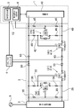
- the power storage device 100 of FIG. 1 includes a power conversion device 2 to which power is supplied from a commercial power source 9 to supply power to a load 8, a battery module 1 including a plurality of rechargeable battery cells 11 and an assembled battery control circuit 12.
- a switching circuit 3 for switching the supply of power from the power converter 2 and the battery module 1 to the assembled battery control circuit 12, and a state in which power is supplied from the power converter 2 to the assembled battery control circuit 12 are detected and a connection signal is output. It includes a connection detection unit 5 that outputs power, and a discharge stop determination unit 6 that detects that the discharged battery module 1 is in a discharge stop state and outputs a discharge stop signal.
- the battery module 1 includes an assembled battery 10 connected to a plurality of rechargeable battery cells 11 and an assembled battery control circuit 12 connected to the assembled battery 10 to control charging / discharging of the assembled battery 10.
- the present invention does not specify the circuit configuration of the assembled battery control circuit 12, but the assembled battery control circuit 12 detects, for example, the voltage and the remaining capacity of the assembled battery 10 and the battery cell 11, or the battery cell 11. It is provided with a protection circuit such as a circuit for equalizing the voltage and the remaining capacity of the assembled battery 10 and a charge / discharge control circuit.
- the power conversion device 2 supplies the electric power supplied from the commercial power source 9 to the battery module 1 to charge the battery module 1.
- the power conversion device 2 includes a converter 21 that converts commercial power into the charging voltage of the battery module 1, and a DC / AC inverter 22 that converts the direct current output from the battery module 1 into an AC voltage supplied to the load 8. There is.
- a load 8 is connected to the output side of the DC / AC inverter 22.
- the power conversion device 2 is provided with a bus line 23 that directly supplies the commercial power source 9 to the load 8. In a state where the commercial power is supplied, the power conversion device 2 supplies the power to the load 8 via the bus line 23.
- the power supply circuit of the assembled battery control circuit 12 is connected to the power converter 2 and the battery module 1 via the DC / DC converter 4 and the switching circuit 3, and is DC from either or both of the power converter 2 and the battery module 1.
- DC operating power is supplied via the / DC converter 4.
- the DC / DC converter 4 converts, for example, a high voltage of the power converter 2 or the battery module 1, for example, 400V to 600V, into a power supply voltage of the assembled battery control circuit 12, for example, a direct current of 24V to 5V, and outputs the voltage.
- the switching circuit 3 switches a state in which operating power is supplied to the assembled battery control circuit 12 from either or both of the power conversion device 2 and the battery module 1 via the DC / DC converter 4.
- the switching circuit 3 supplies operating power from the power conversion device 2 to the assembled battery control circuit 12 in a state where the output voltage of the power conversion device 2 is higher than the set voltage.
- the connection detection unit 5 detects a state in which the power conversion device 2 starts supplying power to the assembled battery control circuit 12.
- the connection detection unit 5 detects the start of power supply from the power conversion device 2, it outputs a connection signal to the switching circuit 3.
- the switching circuit 3 When a connection signal is input from the connection detection unit 5 to the switching circuit 3, the switching circuit 3 starts supplying operating power from the battery module 1 to the assembled battery control circuit 12.
- the battery module 1 When power is supplied from the battery module 1 to the assembled battery control circuit 12, the battery module 1 is discharged, and the discharge stop determination unit 6 detects the discharge stop state of the battery module 1, the discharge stop determination unit 6 sends the switching circuit 3 to the switching circuit 3. Outputs a discharge stop signal.
- the switching circuit 3 stops the power supply from the battery module 1 to the assembled battery control circuit 12.
- the discharge stop determination unit 6 stores the condition for stopping the discharge of the battery module 1.
- the discharge stop signal is output to the switching circuit 3, and the switching circuit 3 outputs the discharge stop signal to the battery module 1.
- the power supply to the assembled battery control circuit 12 is stopped.
- the switching circuit 3 shown in FIG. 2 switches the connection between the DC / DC converter 4, the power converter 2 and the battery module 1, supplies power from the power converter 2 to the assembled battery control circuit 12, and the battery module 1. Controls the power supply to the assembled battery control circuit 12.
- the switching circuit 3 of FIG. 2 controls the power supply from the power converter 2 to the DC / DC converter 4 with the first power switch 31.
- the first power switch 31 is controlled on and off by the first input circuit 32.
- the first input circuit 32 compares the output voltage of the power conversion device 2 with the set voltage, and controls the first power switch 31 on and off.
- the first power switch 31 is an n-channel power MOSFET, which is connected between the negative output terminal of the power converter 2 and the DC / DC converter 4.
- the first power switch 31 connects the backflow prevention diode 33 in series, and connects the negative side of the power converter 2 to the DC / DC converter 4 via a series circuit of the first power switch 31 and the backflow prevention diode 33. You are connected.
- the first power switch 31 is controlled on and off by the first input circuit 32, supplies power from the power converter 2 to the DC / DC converter 4 in the on state, and is a battery control circuit from the DC / DC converter 4. 12 is supplied with operating power.
- the first power switch 31 cuts off the power supply to the DC / DC converter 4 in the off state, and stops the power supply from the power converter 2 to the assembled battery control circuit 12.
- the first input circuit 32 supplies power from the power converter 2 to the DC / DC converter 4 with the first power switch 31 turned on when the output voltage of the power converter 2 is higher than the set voltage. Operating power is supplied from the power converter 2 to the assembled battery control circuit 12, and when the output voltage of the power converter 2 is lower than the set voltage, the first power switch 31 is switched to the off state, and the power converter 2 starts the power converter 2.
- the power supply to the DC / DC converter 4, that is, the power supply to the assembled battery control circuit 12 is cut off.
- the set voltage is set lower than the output voltage of the power converter 2 in the state where commercial power is supplied. When the output voltage of the power conversion device 2 is higher than the set voltage, it is connected to the commercial power. In this state, the power conversion device 2 supplies the operating power to the assembled battery control circuit 12.
- the first input circuit 32 includes a first control switch 34 that turns on and off the first power switch 31.
- the first control switch 34 is controlled on and off by the output voltage of the power conversion device 2, and switches the first power switch 31 on and off.
- the first control switch 34 is an n-channel FET, and controls the first power switch 31 on and off by turning on and off the first control FET 34A.
- the first control FET 34A switches the first power switch 31 to the on state when it is on, and turns the first power switch 31 to the off state when it is off.
- the first control FET 34A which is the first control switch 34, connects the gate to the output side of the power conversion device 2 via the first input resistor 35, and is controlled on and off by the output voltage of the power conversion device 2.
- the first control FET 34A connects the drain to the positive output of the power converter 2 via the second input resistor 36 and the source to the ground line 39 via the second input resistor 36.
- the first control FET 34A is switched on and off by the voltage input to the gate from the first input resistor 35, and the first input resistors 35 and 35 are voltage dividing resistors to control the output voltage of the power converter 2. The voltage is divided and input to the gate of the first control FET 34A.
- the first input resistors 35, 35 which are voltage dividing resistors, divide the output voltage of the power conversion device 2 at a specific ratio and input it to the gate of the first control FET 34A.
- the electrical resistance of the voltage dividing resistor divides the output voltage of the power converter 2 to which commercial power is supplied and inputs it to the gate of the first control FET 34A to turn on the first control FET 34A for power conversion.
- the output voltage in a state where commercial power is not supplied to the device 2 is set to a resistance value that turns off the first control FET 34A.
- the first power FET 31A which is the MOSFET of the first power switch 31, is switched to the on state when the first control FET 34A is on.
- the first power FET 31A connects the gate to the drain of the first control FET 34A and inputs the drain voltage of the first control FET 34A.
- the first power FET 31A is switched on and off by the voltage input to the gate from the drain of the first control FET 34A.
- the second input resistors 36, 36 connected in series serve as voltage dividing resistors, and the output voltage of the power converter 2 is divided and input to the gate of the first power FET 31A. ..
- the second input resistors 36, 36 which are voltage dividing resistors, divide the output voltage of the power converter 2 at a specific ratio and input it to the gate of the first power FET 31A.
- the electrical resistance of the voltage dividing resistor is a resistance value that divides the output voltage of the power converter 2 to which commercial power is supplied and inputs it to the gate of the first power FET 31A to turn on the first power FET 31A. Is set to. Therefore, in the on state of the first control FET 34A, the gate voltage (VGS) of the first power FET 31A becomes the on voltage, and in the off state of the first control FET 34A, the voltage input to the gate of the first power FET 31A.
- the first power FET 31A supplies power from the power converter 2 to the DC / DC converter 4 in the on state, and cuts off the power supply from the power converter 2 to the DC / DC converter 4 in the off state.
- connection detection unit 5 detects a state in which power is supplied from the power conversion device 2 to the assembled battery control circuit 12, and outputs a connection signal to the switching circuit 3.
- the switching circuit 3 detects the connection signal input from the connection detection unit 5 and supplies electric power from the battery module 1 to the assembled battery control circuit 12.
- the connection detection unit 5 detects that the power conversion device 2 supplies the operating power to the assembled battery control circuit 12 and activates the assembled battery control circuit 12, and the power conversion device 2 detects that the assembled battery control circuit 12 is activated. Detects that power supply has started and outputs a connection signal. At this time, the connection detection unit 5 outputs a connection signal when the battery module 1 is in a dischargeable state.
- connection detection unit 5 can also detect the ON state of the first control switch 34 or the first power switch 31 of the first input circuit 32 and output the connection signal.
- the connection detection unit 5 has all circuit configurations capable of detecting that the power conversion device 2 has started supplying power to the assembled battery control circuit 12 via the DC / DC converter 4, for example, the DC / DC converter from the power conversion device 2. It is also possible to detect the output current supplied to 4 and output the connection signal.
- the switching circuit 3 may be provided with a dedicated circuit, but is preferably built in the assembled battery control circuit 12.
- the discharge stop determination unit 6 detects a state in which the discharge from the battery module 1 is stopped, and outputs a discharge stop signal to the switching circuit 3.
- the discharge stop determination unit 6 detects, for example, the voltage and the remaining capacity of the battery module 1 to be discharged, and determines whether to allow or stop the discharge of the battery module 1 in order to prevent over-discharge of the battery. When the battery module 1 stops discharging, a discharge stop signal is output.
- the discharge stop determination unit 6 preferably detects the voltage and the remaining capacity of the battery module 1 and outputs a discharge stop signal, but all other parameters for stopping the discharge of the battery module 1, such as the battery temperature, etc. Can be detected and a discharge stop signal can be output.
- the discharge stop determination unit 6 can be built in the assembled battery control circuit 12, or can be provided separately from the assembled battery control circuit 12 as a dedicated circuit configuration.
- the switching circuit 3 of FIG. 2 controls the power supply from the battery module 1 to the DC / DC converter 4 with the second power switch 41.
- the second power switch 41 is controlled on and off by the second input circuit 42.
- the second input circuit 42 is a connection signal input from the connection detection unit 5, starts supplying power from the battery module 1 to the assembled battery control circuit 12, and is a discharge stop signal input from the discharge stop determination unit 6. , The power supply from the battery module 1 to the assembled battery control circuit 12 is stopped.
- the second power switch 41 is turned on by the connection signal input from the connection detection unit 5, power is supplied from the battery module 1 to the DC / DC converter 4, and the assembled battery control circuit is supplied from the battery module 1.
- the discharge stop determination unit 6 detects the discharge stop signal by detecting the voltage and the remaining capacity of the battery module 1 in order to prevent the battery module 1 from over-discharging.
- the second input circuit 42 includes a second control switch 44 and a second power switch 41 that is controlled on and off by the second control switch 44.
- the second control switch 44 is controlled by a connection signal input from the connection detection unit 5.
- the second power switch 41 is controlled on and off by the second control switch 44.
- the second control switch 44 and the second power switch 41 are n-channel FETs, and the second power switch 41 is a power MOSFET.
- the second control switch 44 switches the second power switch 41 to the on state when it is on, and switches the second power switch 41 to the off state when it is off.
- the gate is connected to the connection detection unit 5, the drain is connected to the positive output of the battery module 1 via the fourth input resistor 46, and the source is connected to the fourth input resistor. It is connected to the ground line 49 via 46.
- the second control FET 44A is controlled on and off by a connection signal input from the connection detection unit 5 to the gate.
- the second control FET 44A connects the gate to the output terminal of the battery module 1 via the third input resistor 45, and the third input resistor 45 is a voltage dividing resistor to control the output voltage of the battery module 1. The voltage is divided and input to the gate of the second control FET 44A.
- the third input resistor 45 which is the voltage dividing resistor, controls the second power FET 41A, which is the second power switch 41, via the second control FET 44A in the normal voltage range of the battery module 1.
- the resistance value of the voltage dividing resistor is set to a resistance value that does not turn on the second control FET 44A when the output voltage of the battery module 1 is within the specified range.
- the second input circuit 42 turns on the second control FET 44A while the connection signal is input from the connection detection unit 5 to the gate of the second control FET 44A.
- the second power FET 41A which is the MOSFET of the second power switch 41, is switched to the on state when the second control FET 44A is in the off state.
- the second power FET 41A connects the gate to the drain of the second control FET 44A and inputs the drain voltage of the second control FET 44A.
- the second power FET 41A is switched on and off by the voltage input to the gate from the drain of the second control FET 44A.
- the fourth input resistors 46 and 46 connected in series serve as voltage dividing resistors, divide the output voltage of the battery module 1 and input it to the gate of the second power FET 41A.
- the fourth input resistors 46, 46 which are voltage dividing resistors, divide the output voltage of the battery module 1 at a specific ratio and input it to the gate of the second power FET 41A.
- the electric resistance of the voltage dividing resistor is set to a resistance value that divides the output voltage of the battery module 1 and inputs it to the gate of the second power FET 41A to turn on the second power FET 41A. Therefore, in the on state of the second control FET 44A, the gate voltage (VGS) of the second power FET 41A becomes the on voltage, and in the off state of the second control FET 44A, the voltage input to the gate of the second power FET 41A.
- the second power FET 41A supplies power from the battery module 1 to the DC / DC converter 4 in the on state, and cuts off the power supply from the battery module 1 to the DC / DC converter 4 in the off state.
- the connection detection unit 5 inputs a “High” level connection signal to the gate of the second control FET 44A to enter a second control FET 44A.
- the control FET 44A of the above is turned on, and the second power FET 41A is turned on.
- the discharge stop determination unit 6 inputs a “Low” level discharge stop signal to the gate of the second control FET 44A to turn the second control FET 44A into an off state and turn the second power FET 41A into an off state.
- the discharge stop determination unit 6 inputs a “Low” level discharge stop signal to the gate of the second control FET 44A to turn the second control FET 44A into an off state, and the second control FET 44A in the off state makes a second.
- the power FET 41A of the above is turned off, and the power supply from the battery module 1 to the assembled battery control circuit 12 is stopped.
- a backflow prevention diode 33 is connected between the output side of the power converter 2 and the DC / DC converter 4, and the backflow prevention diode 33 is also connected between the output side of the battery module 1 and the DC / DC converter 4.
- the backflow prevention diode 43 is connected.
- the backflow prevention diodes 33 and 43 are connected in such a direction that the power converter 2 can supply power to the DC / DC converter 4 side and the battery module 1 can supply power to the DC / DC converter 4 side, and the DC / DC The power supply from the converter 4 to the power converter 2 and the battery module 1 is blocked.
- the present invention can be suitably used for various power storage devices as a power supply system and a power storage device capable of stably supplying operating power to a battery control circuit from both commercial power and a battery module.
Landscapes
- Engineering & Computer Science (AREA)
- Power Engineering (AREA)
- Manufacturing & Machinery (AREA)
- Chemical & Material Sciences (AREA)
- Chemical Kinetics & Catalysis (AREA)
- Electrochemistry (AREA)
- General Chemical & Material Sciences (AREA)
- Business, Economics & Management (AREA)
- Emergency Management (AREA)
- Charge And Discharge Circuits For Batteries Or The Like (AREA)
- Secondary Cells (AREA)
Priority Applications (3)
| Application Number | Priority Date | Filing Date | Title |
|---|---|---|---|
| US17/911,265 US12412938B2 (en) | 2020-03-30 | 2021-03-24 | Electric power supply system for battery assembly control circuit of electricity storage device, and electricity storage device |
| CN202180015792.8A CN115152121A (zh) | 2020-03-30 | 2021-03-24 | 蓄电装置的电池组控制电路的电力供给方式及蓄电装置 |
| JP2022512015A JP7682162B2 (ja) | 2020-03-30 | 2021-03-24 | 蓄電装置の組電池制御回路の電力供給方式、及び蓄電装置 |
Applications Claiming Priority (2)
| Application Number | Priority Date | Filing Date | Title |
|---|---|---|---|
| JP2020-061461 | 2020-03-30 | ||
| JP2020061461 | 2020-03-30 |
Publications (1)
| Publication Number | Publication Date |
|---|---|
| WO2021200445A1 true WO2021200445A1 (ja) | 2021-10-07 |
Family
ID=77928738
Family Applications (1)
| Application Number | Title | Priority Date | Filing Date |
|---|---|---|---|
| PCT/JP2021/012184 Ceased WO2021200445A1 (ja) | 2020-03-30 | 2021-03-24 | 蓄電装置の組電池制御回路の電力供給方式、及び蓄電装置 |
Country Status (4)
| Country | Link |
|---|---|
| US (1) | US12412938B2 (https=) |
| JP (1) | JP7682162B2 (https=) |
| CN (1) | CN115152121A (https=) |
| WO (1) | WO2021200445A1 (https=) |
Families Citing this family (1)
| Publication number | Priority date | Publication date | Assignee | Title |
|---|---|---|---|---|
| JP7002701B2 (ja) * | 2019-06-20 | 2022-01-20 | 三菱電機株式会社 | 電力変換システム |
Citations (1)
| Publication number | Priority date | Publication date | Assignee | Title |
|---|---|---|---|---|
| WO2015186282A1 (ja) * | 2014-06-03 | 2015-12-10 | ソニー株式会社 | 電力供給装置および電力供給方法 |
Family Cites Families (10)
| Publication number | Priority date | Publication date | Assignee | Title |
|---|---|---|---|---|
| US7939968B2 (en) * | 2004-08-31 | 2011-05-10 | American Power Conversion Corporation | Method and apparatus for providing uninterruptible power |
| JP4406655B2 (ja) * | 2007-06-28 | 2010-02-03 | 日本電信電話株式会社 | 電源システム |
| JP4937146B2 (ja) * | 2008-01-22 | 2012-05-23 | 三洋電機株式会社 | 車両用の電源装置 |
| JP2012065518A (ja) | 2010-09-17 | 2012-03-29 | Toshiba Corp | 組電池モジュール、二次電池装置、および、車両 |
| CN103733468A (zh) * | 2011-08-19 | 2014-04-16 | 日本电产株式会社 | 风力发电装置 |
| US9231440B2 (en) * | 2012-04-18 | 2016-01-05 | Samsung Sdi Co., Ltd. | Power supply apparatus and controlling method of the same |
| US9825487B2 (en) * | 2012-10-31 | 2017-11-21 | Panasonic Intellectual Property Management Co., Ltd. | Apparatus and electric power control method |
| JP6272971B2 (ja) * | 2015-07-01 | 2018-01-31 | 三菱電機株式会社 | 電源切替装置及び住宅 |
| CN106410955B (zh) * | 2016-10-28 | 2019-03-22 | 北京航天控制仪器研究所 | 一种用于重力测量的不间断电源电路 |
| JP6324575B1 (ja) | 2017-04-06 | 2018-05-16 | 三菱電機株式会社 | 電力変換装置 |
-
2021
- 2021-03-24 JP JP2022512015A patent/JP7682162B2/ja active Active
- 2021-03-24 WO PCT/JP2021/012184 patent/WO2021200445A1/ja not_active Ceased
- 2021-03-24 CN CN202180015792.8A patent/CN115152121A/zh active Pending
- 2021-03-24 US US17/911,265 patent/US12412938B2/en active Active
Patent Citations (1)
| Publication number | Priority date | Publication date | Assignee | Title |
|---|---|---|---|---|
| WO2015186282A1 (ja) * | 2014-06-03 | 2015-12-10 | ソニー株式会社 | 電力供給装置および電力供給方法 |
Also Published As
| Publication number | Publication date |
|---|---|
| JPWO2021200445A1 (https=) | 2021-10-07 |
| JP7682162B2 (ja) | 2025-05-23 |
| US12412938B2 (en) | 2025-09-09 |
| US20230099799A1 (en) | 2023-03-30 |
| CN115152121A (zh) | 2022-10-04 |
Similar Documents
| Publication | Publication Date | Title |
|---|---|---|
| US6879134B2 (en) | Selector circuit for power management in multiple battery systems | |
| US6175511B1 (en) | Uninterruptable power supply | |
| EP2317597B1 (en) | Battery pack | |
| US8203234B2 (en) | Power safety system | |
| KR102458732B1 (ko) | 배터리 모듈 및 그 작동 방법 | |
| US20080169784A1 (en) | Solar power system | |
| US20050168194A1 (en) | Selector circuit for power management in multiple battery systems | |
| KR20060047861A (ko) | 전원 장치 및 그 전원 장치에 이용되는 제어 방법 | |
| CN101467327A (zh) | 2次电池的充放电电路以及电池组 | |
| JP2012191838A (ja) | 電池パック、電動工具、電池パックと電動工具とを接続するアダプタ、及び、電動工具システム | |
| WO2011148908A1 (ja) | 太陽電池システム | |
| JP4688725B2 (ja) | 電源装置 | |
| CN112438008A (zh) | 不间断电源装置 | |
| JP7682162B2 (ja) | 蓄電装置の組電池制御回路の電力供給方式、及び蓄電装置 | |
| US20070229022A1 (en) | Power-Supply Unit | |
| JP2005012958A (ja) | バッテリ装置 | |
| KR101837548B1 (ko) | 커패시터 관리 시스템 | |
| JP2015073377A (ja) | 太陽電池電源装置 | |
| KR0182665B1 (ko) | 전기 자동차의 충전 시스템 | |
| JP5288976B2 (ja) | ハイブリッドバッテリの充電制御方法 | |
| US20250266709A1 (en) | Backup power supply | |
| JP2005135854A (ja) | 電池パック | |
| EP4601147A1 (en) | Method for battery over-discharge prevention and battery system providing same | |
| EP4629473A1 (en) | Battery pack | |
| JP7849744B2 (ja) | 電力供給装置 |
Legal Events
| Date | Code | Title | Description |
|---|---|---|---|
| 121 | Ep: the epo has been informed by wipo that ep was designated in this application |
Ref document number: 21781392 Country of ref document: EP Kind code of ref document: A1 |
|
| ENP | Entry into the national phase |
Ref document number: 2022512015 Country of ref document: JP Kind code of ref document: A |
|
| NENP | Non-entry into the national phase |
Ref country code: DE |
|
| 122 | Ep: pct application non-entry in european phase |
Ref document number: 21781392 Country of ref document: EP Kind code of ref document: A1 |
|
| WWG | Wipo information: grant in national office |
Ref document number: 17911265 Country of ref document: US |