WO2021199825A1 - ベルト、及び、心電測定装置 - Google Patents
ベルト、及び、心電測定装置 Download PDFInfo
- Publication number
- WO2021199825A1 WO2021199825A1 PCT/JP2021/007617 JP2021007617W WO2021199825A1 WO 2021199825 A1 WO2021199825 A1 WO 2021199825A1 JP 2021007617 W JP2021007617 W JP 2021007617W WO 2021199825 A1 WO2021199825 A1 WO 2021199825A1
- Authority
- WO
- WIPO (PCT)
- Prior art keywords
- belt
- electrode
- electrocardiographic
- electrode pieces
- measuring device
- Prior art date
- Legal status (The legal status is an assumption and is not a legal conclusion. Google has not performed a legal analysis and makes no representation as to the accuracy of the status listed.)
- Ceased
Links
Images


Classifications
-
- A—HUMAN NECESSITIES
- A61—MEDICAL OR VETERINARY SCIENCE; HYGIENE
- A61B—DIAGNOSIS; SURGERY; IDENTIFICATION
- A61B5/00—Measuring for diagnostic purposes; Identification of persons
- A61B5/24—Detecting, measuring or recording bioelectric or biomagnetic signals of the body or parts thereof
- A61B5/25—Bioelectric electrodes therefor
- A61B5/251—Means for maintaining electrode contact with the body
- A61B5/256—Wearable electrodes, e.g. having straps or bands
-
- A—HUMAN NECESSITIES
- A61—MEDICAL OR VETERINARY SCIENCE; HYGIENE
- A61B—DIAGNOSIS; SURGERY; IDENTIFICATION
- A61B5/00—Measuring for diagnostic purposes; Identification of persons
- A61B5/24—Detecting, measuring or recording bioelectric or biomagnetic signals of the body or parts thereof
- A61B5/25—Bioelectric electrodes therefor
- A61B5/279—Bioelectric electrodes therefor specially adapted for particular uses
- A61B5/28—Bioelectric electrodes therefor specially adapted for particular uses for electrocardiography [ECG]
- A61B5/282—Holders for multiple electrodes
-
- A—HUMAN NECESSITIES
- A61—MEDICAL OR VETERINARY SCIENCE; HYGIENE
- A61B—DIAGNOSIS; SURGERY; IDENTIFICATION
- A61B5/00—Measuring for diagnostic purposes; Identification of persons
- A61B5/24—Detecting, measuring or recording bioelectric or biomagnetic signals of the body or parts thereof
- A61B5/316—Modalities, i.e. specific diagnostic methods
- A61B5/318—Heart-related electrical modalities, e.g. electrocardiography [ECG]
- A61B5/332—Portable devices specially adapted therefor
-
- A—HUMAN NECESSITIES
- A61—MEDICAL OR VETERINARY SCIENCE; HYGIENE
- A61B—DIAGNOSIS; SURGERY; IDENTIFICATION
- A61B5/00—Measuring for diagnostic purposes; Identification of persons
- A61B5/68—Arrangements of detecting, measuring or recording means, e.g. sensors, in relation to patient
- A61B5/6801—Arrangements of detecting, measuring or recording means, e.g. sensors, in relation to patient specially adapted to be attached to or worn on the body surface
- A61B5/6813—Specially adapted to be attached to a specific body part
- A61B5/6824—Arm or wrist
-
- A—HUMAN NECESSITIES
- A61—MEDICAL OR VETERINARY SCIENCE; HYGIENE
- A61B—DIAGNOSIS; SURGERY; IDENTIFICATION
- A61B5/00—Measuring for diagnostic purposes; Identification of persons
- A61B5/68—Arrangements of detecting, measuring or recording means, e.g. sensors, in relation to patient
- A61B5/6801—Arrangements of detecting, measuring or recording means, e.g. sensors, in relation to patient specially adapted to be attached to or worn on the body surface
- A61B5/683—Means for maintaining contact with the body
- A61B5/6831—Straps, bands or harnesses
-
- A—HUMAN NECESSITIES
- A61—MEDICAL OR VETERINARY SCIENCE; HYGIENE
- A61B—DIAGNOSIS; SURGERY; IDENTIFICATION
- A61B5/00—Measuring for diagnostic purposes; Identification of persons
- A61B5/02—Detecting, measuring or recording for evaluating the cardiovascular system, e.g. pulse, heart rate, blood pressure or blood flow
- A61B5/021—Measuring pressure in heart or blood vessels
- A61B5/02108—Measuring pressure in heart or blood vessels from analysis of pulse wave characteristics
-
- A—HUMAN NECESSITIES
- A61—MEDICAL OR VETERINARY SCIENCE; HYGIENE
- A61B—DIAGNOSIS; SURGERY; IDENTIFICATION
- A61B5/00—Measuring for diagnostic purposes; Identification of persons
- A61B5/24—Detecting, measuring or recording bioelectric or biomagnetic signals of the body or parts thereof
- A61B5/316—Modalities, i.e. specific diagnostic methods
- A61B5/318—Heart-related electrical modalities, e.g. electrocardiography [ECG]
- A61B5/339—Displays specially adapted therefor
Definitions
- the present invention relates to a belt and an electrocardiographic measuring device used for measuring a biological signal according to an electric potential on the surface of a living body caused by the movement of the heart.
- an electrocardiographic measuring device that detects an electrocardiographic signal which is a voltage generated on the surface of a living body caused by the movement of the heart and generates an electrocardiogram waveform of a user.
- an electrocardiographic measuring device using a belt having a belt main body wrapped around the user's upper arm and a plurality of electrodes fixed at equal intervals in the longitudinal direction on the inner surface of the belt main body is known. (See, for example, Patent Document 1).
- the area of the electrode in contact with the living body is large in order to increase the detection intensity of the electrocardiographic signal. Therefore, it is conceivable to increase the area of the surface of the electrode in contact with the upper arm. For example, it is conceivable to form the electrode in a shape as large as possible in the range from one end to the other end in the lateral direction of the belt.
- the surface of the living body is composed of curved surfaces. Therefore, if the area of the surface of the electrode on the living body side is increased, the area of the electrode that does not come into contact with the living body becomes large. That is, the degree of adhesion of the electrode to the living body is reduced.
- an object of the present invention is to provide a belt that can be brought into close contact with the living body of the electrode and an electrocardiographic measuring device.
- the belt is a belt main body formed in a band shape, and a plurality of belts provided on one main surface of the belt main body, arranged in the lateral direction of the belt main body, and connected in series by a signal line.
- the plurality of electrode pieces follow the surface of the living body on which the plurality of electrode pieces face each other. That is, the postures of the plurality of electrode pieces change according to the surface of the living body.
- the surface of the electrode on the living body side which is composed of the surface of the plurality of electrode pieces on the living body side, follows the living body. Therefore, the electrodes are in close contact with the living body.
- a belt in which the lengths of the plurality of electrode pieces along the lateral direction are equal.
- the electrode can be formed of electrode pieces having the same shape and the same size, the manufacturing cost of the electrode can be reduced.
- the plurality of electrode pieces are three electrode pieces, and among the plurality of electrode pieces, the lengths of the electrode pieces arranged at both ends in the short side direction along the short side direction.
- both ends of the electrode can be brought into close contact with the living body in the lateral direction of the belt body of the electrode, which is difficult to be brought into close contact with the living body, while preventing the number of electrode pieces included in the electrode from increasing. Further, since it is possible to prevent the number of electrode pieces from increasing, the number of signal lines can be reduced, so that the noise generated by the signal lines can be reduced.
- the belt of the above aspect it is possible to provide a belt in which a plurality of the electrodes are provided.
- a plurality of electrodes can be brought into close contact with the living body.
- an electrocardiogram including the belt of the above aspect, a device main body incorporating a control board, and a wiring portion provided on the belt main body and electrically connecting the control board and the electrodes.
- a measuring device is provided.
- the plurality of electrode pieces follow the surface of the living body on which the plurality of electrode pieces face each other. That is, the postures of the plurality of electrode pieces change according to the surface of the living body.
- the surface of the electrode on the living body side which is composed of the surface of the plurality of electrode pieces on the living body side, follows the living body. Therefore, the electrodes are in close contact with the living body. Since the electrodes are in close contact with the living body, the electrocardiographic measuring device can suitably detect the voltage generated on the surface of the living body, and can measure the electrocardiogram waveform more accurately.
- the present invention can provide a belt capable of bringing electrodes into close contact with a living body and an electrocardiographic measuring device.
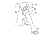
- FIG. 1 is an explanatory view showing a state in which an electrocardiographic measuring device according to an embodiment of the present invention is attached to a user's upper arm.
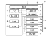
- FIG. 2 is a block diagram showing a configuration of a concentric electrocardiographic measuring device.
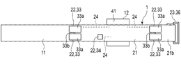
- FIG. 3 is a plan view showing the configuration of the concentric electrocardiographic measuring device.
- FIG. 4 is a perspective view showing the configuration of the concentric electrocardiographic measuring device.
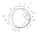
- FIG. 5 is a cross-sectional view schematically showing a state in which the concentric electrocardiographic measuring device is attached to the upper arm.
- FIG. 6 is a plan view showing a configuration of a modified example of the electrocardiographic measuring device according to the embodiment of the present invention.
- FIG. 1 is an explanatory view showing a state in which an electrocardiographic measuring device according to an embodiment of the present invention is attached to a user's upper arm.
- FIG. 2 is a block diagram showing a configuration of a concentric electrocardiographic measuring device.
- FIG. 3
- FIG. 7 is a cross-sectional view schematically showing a state in which the concentric electrocardiographic measuring device is attached to the upper arm.
- FIG. 8 is a plan view showing a configuration of a modified example of the electrocardiographic measuring device according to the embodiment of the present invention.
- FIG. 9 is a cross-sectional view schematically showing a state in which the concentric electrocardiographic measuring device is attached to the upper arm.
- FIG. 10 is a plan view showing a configuration of a modified example of the electrocardiographic measuring device according to the embodiment of the present invention.
- FIG. 1 is an explanatory view showing a state in which the electrocardiographic measuring device 1 is attached to the user's upper arm 100.
- FIG. 2 is a block diagram showing the configuration of the electrocardiographic measuring device 1.
- FIG. 3 is a plan view showing the configuration of the electrocardiographic measuring device 1.
- FIG. 3 shows a state in which the belt 11 of the electrocardiographic measuring device 1 is unfolded.
- FIG. 4 is a perspective view showing the configuration of the electrocardiographic measuring device 1.
- FIG. 5 is a cross-sectional view schematically showing a state in which the electrocardiographic measuring device 1 is attached to the upper arm 100.
- the electrocardiographic measuring device 1 is a potential measuring device that is attached to a living body, detects potentials at a plurality of locations on the surface of the skin of the living body, and generates electrocardiographic information necessary for generating an electrocardiogram based on the detected voltages. ..
- the electrocardiogram measuring device 1 may generate and display an electrocardiogram waveform, or may be configured to display information necessary for generating an electrocardiogram and output it to an external terminal.
- the electrocardiographic measuring device 1 includes a belt 11 and a device main body 12.
- the belt 11 and the device main body 12 are integrally formed.
- the electrocardiographic measuring device 1 functions as a so-called wearable device that is attached to the upper arm 100 as a living body by, for example, a belt 11.
- FIG. 1 shows an example of a state in which the electrocardiographic measuring device 1 is attached to the upper arm 100 of the person to be measured.
- the electrocardiographic measuring device 1 may be configured such that the belt 11 and the device main body 12 are separately configured and connected via a signal line or the like.
- the belt 11 holds the device main body 12.
- the belt 11 is wrapped around the upper arm 100.
- the belt 11 includes a belt main body 21, an electrode array 22, a fixing means 23, and a wiring portion 24.
- the belt body 21 is made of, for example, a flexible resin or fiber.
- the belt body 21 is set to a length that can be worn on the upper arm 100 of the person to be measured who wears the electrocardiographic measuring device 1.
- the belt body 21 is formed in a long strip shape in one direction.
- the electrode array 22 is electrically connected to the control board 40 described later of the apparatus main body 12 via the wiring unit 24.
- the electrode array 22 includes a plurality of electrodes 33 and a ground electrode 34.
- the plurality of electrodes 33 are provided on the other main surface 21b of the belt body 21.
- the plurality of electrodes 33 are arranged apart from each other in the longitudinal direction of the belt body 21.
- the plurality of electrodes 33 are electrically connected to the electrocardiographic information generation unit 45, which will be described later, by the wiring unit 24. In other words, the plurality of electrodes 33 are electrically connected to the control substrate 40.
- the plurality of electrodes 33 are, for example, two electrodes 33.
- the electrodes 33 are provided on the belt main body 21 and are arranged in the lateral direction of the belt main body 21, and the belt main body 21 is wound around the upper arm 100 to form a plurality of electrode pieces 33a whose postures can be changed according to the upper arm 100.
- a signal line 33b for connecting a plurality of electrode pieces 33a in series is provided.
- the plurality of electrode pieces 33a are made of a conductive material.
- the plurality of electrode pieces 33a are fixed to the belt body 21.
- the plurality of electrode pieces 33a are formed, for example, in the same shape and the same size.
- the electrode piece 33a is formed, for example, in the shape of a rectangular plate.
- the main surface of the electrode piece 33a on the upper arm side is formed, for example, as a flat surface.
- the plurality of electrode pieces 33a are fixed to the belt body 21 in a posture in which two sides are parallel to the lateral direction of the belt body 21, for example. Further, in the plurality of electrode pieces 33a, two sides of the belt body 21 along the lateral direction are arranged in a straight line.
- the length of the electrode piece 33a along the short side of the belt body 21 is the sum of the lengths of the plurality of electrode pieces 33a along the short side of the belt body 21 and the length along the short side of the belt body 21. The length is set to be as close as possible.
- a gap is provided between the two electrode pieces 33a arranged adjacent to each other in the lateral direction of the belt body 21 so that the two electrode pieces 33a can be displaced according to the upper arm 100.
- the plurality of electrodes 33 configured in this way may be configured to be detachable from, for example, the belt body 21.
- the signal line 33b connects a plurality of electrode pieces 33a in series.
- the signal line 33b is connected to one electrode piece 33a and the other electrode piece 33a.
- the signal line 33b may be provided in the belt main body 21, for example.
- the ground electrode 34 is provided on the other main surface 21b of the belt body 21.
- the ground electrode 34 is electrically connected to the electrocardiographic information generation unit 45 via the wiring unit 24.
- the ground electrode 34 is electrically connected to the control substrate 40.
- the ground electrode 34 configured in this way may be detachably configured to be attached to or detached from the belt body 21, for example.
- the wiring unit 24 electrically connects the plurality of electrodes 33 and the electrocardiographic information generation unit 45. Further, the wiring unit 24 electrically connects the ground electrode 34 and the electrocardiographic information generation unit 45.
- the fixing means 23 is configured so that the belt body 21 can be fixed to the upper arm 100 in a state where the plurality of electrodes 33 are brought into contact with the upper arm 100 and the belt body 21 is wound around the user's upper arm 100.
- the fixing means 23 includes, for example, a belt fixing ring 36 and a hook-and-loop fastener 37.
- the belt fixing ring 36 is provided at one end in the longitudinal direction of the belt body 21.
- the belt fixing ring 36 is formed in an annular shape into which the belt body 21 can be inserted.
- the hook-and-loop fastener 37 includes a loop 37a and a hook 37b.
- the loop 37a is provided on one main surface 21a of the belt body 21.
- the loop 37a is provided on the main surface 21a in a region facing the other end of the belt body 21 folded back by, for example, the belt fixing ring 36.
- the region of the main surface 21a facing the other end of the belt body 21 is the belt body regardless of the expected circumference of the user's upper arm 100 from the minimum length to the maximum length.
- the size is set so as to face the other end of 21.
- the hook 37b is provided at the other end of the main surface 21a of the belt body 21.
- the wiring unit 24 is composed of, for example, a lead wire embedded in the belt body 21. Further, the wiring portion 24 may be composed of a flexible substrate provided on the main surface 21b of the belt main body 21.
- the apparatus main body 12 includes a case 41, an operation unit 42, a display unit 43, a power supply unit 44, an electrocardiographic information generation unit 45, an electrocardiogram generation unit 46, and a memory. 47 and a control unit 48 are provided.
- the electrocardiographic information generation unit 45, the electrocardiogram generation unit 46, and the control unit 48 are provided on, for example, the control board 40.
- the control board 40 is housed in the case 41.
- the operation unit 42 and the display unit 43 are provided on, for example, the control board 40.
- the device main body 12 includes a communication unit that transmits / receives information to / from an external terminal.
- the communication unit transmits / receives information to / from an external terminal wirelessly and / or by wire. This communication unit is provided on, for example, the control board 40.
- the case 41 accommodates a part of the operation unit 42, a part of the display unit 43, an electrocardiographic information generation unit 45, an electrocardiogram generation unit 46, a memory 47, and a control unit 48. Further, the case 41 exposes a part of the operation unit 42 and a part of the display unit 43 from the outer surface.
- the case 41 is fixed to the belt 11.
- the operation unit 42 inputs a command from the user.
- the operation unit 42 includes a plurality of buttons 42a and sensors that detect the operation of the buttons 42a.
- the operation unit 42 may include a pressure-sensitive touch panel, a capacitive touch panel, or the like, a microphone that receives a sound command, or the like provided on the case 41, the display unit 43, or the like.
- the operation unit 42 converts a command into an electric signal and outputs the electric signal to the control unit 48 when the user operates the operation unit 42.
- the display unit 43 is electrically connected to the control unit 48.
- the display unit 43 is, for example, a liquid crystal display (LCD: Liquid Crystal Display) or an organic electroluminescence display (OELD: Organic Electro Luminescence Display).
- the display unit 43 displays the date and time, electrocardiographic information, electrocardiogram waveform, and the like according to the control signal from the control unit 48.
- the display unit 43 displays various information including blood pressure values such as the displayed systolic blood pressure and diastolic blood pressure and measurement results such as heart rate. May be displayed.
- the power supply unit 44 is a power source.
- the power supply unit 44 is a secondary battery such as a lithium ion battery, for example.
- the power supply unit 44 is electrically connected to the control unit 48.
- the power supply unit 44 supplies power to the control unit 48.
- the power supply unit 44 supplies driving power to the operation unit 42, the display unit 43, the electrocardiographic information generation unit 45, the electrocardiogram generation unit 46, and the memory 47 via the control unit 48 and the control unit 48.
- the electrocardiographic information generation unit 45 is electrically connected to a plurality of electrodes 33 of the electrode array 22, two electrodes 33 in this embodiment, for example, via a wiring unit 24.
- the electrocardiographic information generation unit 45 calculates the potential difference from the voltages detected by the two electrodes 33 and generates electrocardiographic information.
- the electrocardiogram generation unit 46 is electrically connected to the electrocardiographic information generation unit 45.
- the electrocardiogram generation unit 46 generates electrocardiogram information based on the electrocardiographic information generated by the electrocardiographic information generation unit 45.
- the ECG information may include an ECG waveform.
- Such an electrocardiographic information generation unit 45 and an electrocardiogram generation unit 46 are processing circuits capable of executing the functions of the electrocardiographic information generation unit 45 and the electrocardiogram generation unit 46, respectively.
- the electrocardiographic information generation unit 45 and the electrocardiogram generation unit 46 are electrically connected to the control unit 48.
- the control unit 48 includes the processing circuits of the electrocardiographic information generation unit 45 and the electrocardiogram generation unit 46, and executes the program stored in the memory 47 to perform the functions of the electrocardiographic information generation unit 45 and the electrocardiogram generation unit 46. You may do it.
- the electrocardiographic information generation unit 45 or the electrocardiogram generation unit 46 may have a low-pass filter, an amplifier, and an analog / digital converter.
- a potential difference signal is converted into a digital signal by an analog / digital converter after removing unnecessary noise components with a low-pass filter and then amplifying the signal with an amplifier.
- the memory 47 includes, for example, SSD (Solid State Drive), RAM (Random Access Memory), ROM (Read Only Memory), and the like as storage media.
- the memory 47 stores a program necessary for executing various control processes. Further, the memory 47 stores the detected electrocardiographic signal, the generated electrocardiographic information, the electrocardiogram information, and the like. Further, for example, the memory 47 stores such information in chronological order.
- the control unit 48 includes a single processor or a plurality of processors.
- the control unit 48 is formed by one or more processing circuits.
- the control unit 48 is, for example, a CPU (Central Processing Unit).
- the control unit 48 executes the entire operation of the electrocardiographic measuring device 1 and a predetermined operation (function) based on the program stored in the memory 47.
- the control unit 48 executes a predetermined calculation, analysis, processing, or the like according to the read program.
- the control unit 48 controls the operation of the operation unit 42, the display unit 43, the electrocardiographic information generation unit 45, and the electrocardiogram generation unit 46, transmits / receives signals, and supplies electric power.
- the person to be measured winds the belt body 21 around the upper arm 100 with the main surface 21b of the belt body 21 facing the upper arm 100 of the person to be measured, and the other end of the belt body 21 is passed through the belt fixing ring 36 to the belt fixing ring 36. Wrap at.
- the person to be measured then tightens the belt body 21 against the upper arm 100 by pulling the other end of the belt body 21.
- the person to be measured next fixes the hook 37b provided at the other end of the belt body 21 to the loop 37a provided on the belt body 21.
- the electrocardiographic measuring device 1 is attached to the upper arm of the person to be measured. Then, the person to be measured controls each configuration by operating the operation unit 42, and detects the electrocardiographic signal via the two electrodes 33. Then, the electrocardiographic information generation unit 45 generates electrocardiographic information from the electrocardiographic signal, and the electrocardiogram generation unit 46 generates electrocardiographic information from the electrocardiographic information.
- the control unit 48 stores the electrocardiographic information and the electrocardiogram information in the memory 47, and displays information such as the date and time and the electrocardiogram on the display unit 43. Further, the control unit 48 may control the communication unit to transmit various information such as date and time, electrocardiographic information, and electrocardiogram information to an external terminal.
- the belt body 21 is wound around the upper arm 100, so that the plurality of electrode pieces 33a of the plurality of electrodes 33 are arranged with the plurality of electrode pieces 33a of the upper arm 100.
- the posture changes according to the part.
- the surface of the electrode 33 on the upper arm 100 side which is composed of the surface of the plurality of electrode pieces 33a on the upper arm 100 side, changes following the upper arm 100. Therefore, the electrode 33 is in close contact with the upper arm 100. Since the electrode 33 is in close contact with the upper arm 100, the electrocardiographic measuring device 1 can suitably detect the voltage generated on the surface of the upper arm 100. As a result, the electrocardiographic measuring device 1 can measure the electrocardiogram waveform more accurately.
- the plurality of electrode pieces 33a are formed to have the same shape and the same size. Therefore, the manufacturing cost of the electrode 33 can be reduced.
- each of the plurality of electrodes 33 includes a plurality of electrode pieces 33a. Therefore, the plurality of electrodes 33 can be brought into close contact with the upper arm 100.
- the electrode 33 has a configuration including a plurality of electrode pieces 33a, and a configuration including two electrode pieces 33a has been described as an example, but the present invention is not limited to this.
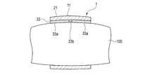
- the electrode 33 may have a configuration including three or more electrode pieces 33a as in the modified examples shown in FIGS. 6 and 7.
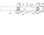
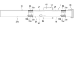
- FIG. 6 is a plan view showing the configuration of an electrocardiographic measuring device 1 in which the electrodes 33 include five electrode pieces 33a as an example.
- FIG. 7 is a cross-sectional view schematically showing a state in which the electrocardiographic measuring device 1 is attached to the user's upper arm 100.
- the configuration in which the plurality of electrode pieces 33a of the electrodes 33 are formed to have the same size has been described as an example, but the present invention is not limited to this.
- at least one of the plurality of electrode pieces 33a may be formed in a different shape and a different size as compared with the others.
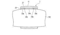
- FIGS. 8 and 9 An example of a configuration in which at least one of the plurality of electrode pieces 33a is formed to have a different size as compared with the others will be described with reference to FIGS. 8 and 9.
- the electrodes 33 include three electrode pieces 33a
- the two electrode pieces 33a arranged at both ends in the lateral direction of the belt main body 21 are oriented in the lateral direction of the belt main body 21.
- the length along the three electrode pieces 33a is shorter than the length along the short side of the belt body 21 of the electrode piece 33a arranged at the center in the short side direction of the belt body 21.
- the length of the two electrode pieces 33a arranged at both ends in the lateral direction of the belt main body 21 among the three electrode pieces 33a along the lateral direction of the belt main body 21 is the lateral direction of the belt main body 21.
- both ends of the belt body 21 of the electrode 33 are separated from the upper arm 100 in the lateral direction.
- both ends of the electrode 33 are formed of the electrode pieces 33a in the lateral direction, the electrode 33 can be brought into close contact with the upper arm 100 of the electrode 33.
- each of the plurality of electrodes 33 includes a plurality of electrode pieces 33a
- the present invention is not limited to this.
- Each one or more of the plurality of electrodes 33 may be configured to include a plurality of electrode pieces 33a.
- one of the three electrodes 33 may be composed of one member.
- FIG. 10 shows, as an example, an electrocardiographic measuring device 1 having a configuration in which electrodes 33 include four electrode pieces 33a, and these four electrode pieces 33a are arranged in two rows of two in each of the short sides of the belt body 21. Is shown. Then, these four electrode pieces 33a are connected in series by a signal line 33b.
- the configuration in which the two electrodes 33 are provided has been described as an example, but the present invention is not limited to this. In another example, three or more electrodes 33 may be provided.
- the electrocardiographic measuring device 1 has been described by using an example in which the belt 11 is attached to the upper arm, but the electrocardiographic measuring device 1 may be attached to the chest or other parts of the living body.
- the belt 11 may have a configuration used in a biometric information measuring device provided for electrocardiographic measurement and blood pressure measurement.
- the biological information measuring device produces a blood pressure measuring function of generating a blood pressure value from the pulse wave sensor and the pulse wave information detected by the pulse wave sensor. It may be configured to have a processing circuit or the like.
- Such a biological information measuring device exerts a blood pressure measurement function of calculating a pulse wave propagation time (PTT) for each heartbeat, estimating blood pressure, and measuring a blood pressure value.
- PTT pulse wave propagation time
- such a biological information measuring device is, for example, a pulse for each heartbeat, which is one of the feature quantities from the R wave peak RP detected by the electrocardiographic signal and the pulse wave signal detected by the pulse wave sensor.
- the pulse wave propagation time (PTT) for each heartbeat is calculated based on the time difference from the wave rising PS.
- the present invention can constitute various inventions by an appropriate combination of a plurality of constituent elements disclosed in each of the above embodiments. For example, some components may be removed from all the components shown in each embodiment. In addition, components from different embodiments may be combined as appropriate.
- Electrocardiographic measuring device 11 ... Belt 12 ... Device main body 21 ... Belt main body 21a ... Main surface 21b ... Main surface 22 ... Electrode array 23 ... Fixing means 24 ... Wiring part 33 ... Electrode 33a ... Electrode piece 33b ... Signal line 34 ... Ground electrode 36 ... Belt fixing ring 37 ... Surface fastener 37a ... Loop 37b ... Hook 41 ... Case 42 ... Operation unit 42a ... Button 43 ... Display unit 44 ... Power supply unit 45 ... Electrocardiographic information generation unit 46 ... Electrocardiogram generation unit 47 ... Memory 48 ... Control unit 100 ... Upper arm
Landscapes
- Health & Medical Sciences (AREA)
- Life Sciences & Earth Sciences (AREA)
- Heart & Thoracic Surgery (AREA)
- Medical Informatics (AREA)
- Biophysics (AREA)
- Pathology (AREA)
- Engineering & Computer Science (AREA)
- Biomedical Technology (AREA)
- Veterinary Medicine (AREA)
- Physics & Mathematics (AREA)
- Molecular Biology (AREA)
- Surgery (AREA)
- Animal Behavior & Ethology (AREA)
- General Health & Medical Sciences (AREA)
- Public Health (AREA)
- Cardiology (AREA)
- Measurement And Recording Of Electrical Phenomena And Electrical Characteristics Of The Living Body (AREA)
Priority Applications (3)
| Application Number | Priority Date | Filing Date | Title |
|---|---|---|---|
| DE112021000615.0T DE112021000615T5 (de) | 2020-03-31 | 2021-03-01 | Manschette und elektrokardiographische messvorrichtung |
| CN202180017523.5A CN115243614A (zh) | 2020-03-31 | 2021-03-01 | 带及心电测定装置 |
| US17/934,920 US20230012616A1 (en) | 2020-03-31 | 2022-09-23 | Belt and electrocardiographic measurement device |
Applications Claiming Priority (2)
| Application Number | Priority Date | Filing Date | Title |
|---|---|---|---|
| JP2020062874A JP7404975B2 (ja) | 2020-03-31 | 2020-03-31 | ベルト、及び、心電測定装置 |
| JP2020-062874 | 2020-03-31 |
Related Child Applications (1)
| Application Number | Title | Priority Date | Filing Date |
|---|---|---|---|
| US17/934,920 Continuation US20230012616A1 (en) | 2020-03-31 | 2022-09-23 | Belt and electrocardiographic measurement device |
Publications (1)
| Publication Number | Publication Date |
|---|---|
| WO2021199825A1 true WO2021199825A1 (ja) | 2021-10-07 |
Family
ID=77928139
Family Applications (1)
| Application Number | Title | Priority Date | Filing Date |
|---|---|---|---|
| PCT/JP2021/007617 Ceased WO2021199825A1 (ja) | 2020-03-31 | 2021-03-01 | ベルト、及び、心電測定装置 |
Country Status (5)
| Country | Link |
|---|---|
| US (1) | US20230012616A1 (enExample) |
| JP (1) | JP7404975B2 (enExample) |
| CN (1) | CN115243614A (enExample) |
| DE (1) | DE112021000615T5 (enExample) |
| WO (1) | WO2021199825A1 (enExample) |
Cited By (1)
| Publication number | Priority date | Publication date | Assignee | Title |
|---|---|---|---|---|
| US12178580B2 (en) | 2019-12-23 | 2024-12-31 | Alimetry Limited | Electrode patch and connection system |
Families Citing this family (2)
| Publication number | Priority date | Publication date | Assignee | Title |
|---|---|---|---|---|
| PL439675A1 (pl) * | 2021-11-29 | 2023-06-05 | Demedar Spółka Z Ograniczoną Odpowiedzialnością | Elektrokardiograficzne urządzenie naramienne i sposób pomiaru sygnału elektrokardiograficznego |
| CN120936287A (zh) * | 2023-07-14 | 2025-11-11 | 深圳市韶音科技有限公司 | 一种心电监控系统及方法 |
Citations (4)
| Publication number | Priority date | Publication date | Assignee | Title |
|---|---|---|---|---|
| JPS57187505U (enExample) * | 1981-05-27 | 1982-11-29 | ||
| JP2008086361A (ja) * | 2006-09-29 | 2008-04-17 | Casio Comput Co Ltd | 生体情報検出装置 |
| JP2018121700A (ja) * | 2017-01-30 | 2018-08-09 | Simplex Quantum株式会社 | 心電センサ、心電データ管理システム、及び車両管理システム |
| JP2019136055A (ja) * | 2018-02-06 | 2019-08-22 | Nok株式会社 | 生体測定電極装置 |
Family Cites Families (10)
| Publication number | Priority date | Publication date | Assignee | Title |
|---|---|---|---|---|
| JP5428889B2 (ja) | 2010-01-21 | 2014-02-26 | セイコーエプソン株式会社 | 心電計測装置 |
| FI20145542A7 (fi) * | 2014-06-12 | 2015-12-13 | Bittium Biosignals Oy | Elektrodipanta bioelektrisen signaalin mittaamiseksi |
| WO2016080804A1 (en) * | 2014-11-20 | 2016-05-26 | Samsung Electronics Co., Ltd. | Apparatus for measuring bioelectrical signals |
| JP6453082B2 (ja) * | 2015-01-19 | 2019-01-16 | 原田電子工業株式会社 | 筋電センサ |
| CN105433922A (zh) * | 2015-12-26 | 2016-03-30 | 深圳市纳福信息技术有限公司 | 用于健康监控的紧身衣服及健康监控方法 |
| CN105997059A (zh) * | 2016-05-06 | 2016-10-12 | 成都和煦医疗科技有限公司 | 基于腹带式的胎心电监护仪及其使用方法 |
| CN106510694A (zh) * | 2016-12-06 | 2017-03-22 | 陈国经 | 一种矩阵胸部弹性心电电极带 |
| KR102288229B1 (ko) * | 2017-06-06 | 2021-08-09 | 애플 인크. | 시계줄의 부착 시스템 |
| CN107582048A (zh) * | 2017-10-16 | 2018-01-16 | 中国人民解放军海军总医院 | 一种柔性心电电极 |
| CN109998542A (zh) * | 2019-04-29 | 2019-07-12 | 东北大学 | 基于织物电极的多通道手部肌电采集腕带 |
-
2020
- 2020-03-31 JP JP2020062874A patent/JP7404975B2/ja active Active
-
2021
- 2021-03-01 WO PCT/JP2021/007617 patent/WO2021199825A1/ja not_active Ceased
- 2021-03-01 CN CN202180017523.5A patent/CN115243614A/zh active Pending
- 2021-03-01 DE DE112021000615.0T patent/DE112021000615T5/de active Pending
-
2022
- 2022-09-23 US US17/934,920 patent/US20230012616A1/en active Pending
Patent Citations (4)
| Publication number | Priority date | Publication date | Assignee | Title |
|---|---|---|---|---|
| JPS57187505U (enExample) * | 1981-05-27 | 1982-11-29 | ||
| JP2008086361A (ja) * | 2006-09-29 | 2008-04-17 | Casio Comput Co Ltd | 生体情報検出装置 |
| JP2018121700A (ja) * | 2017-01-30 | 2018-08-09 | Simplex Quantum株式会社 | 心電センサ、心電データ管理システム、及び車両管理システム |
| JP2019136055A (ja) * | 2018-02-06 | 2019-08-22 | Nok株式会社 | 生体測定電極装置 |
Cited By (2)
| Publication number | Priority date | Publication date | Assignee | Title |
|---|---|---|---|---|
| US12178580B2 (en) | 2019-12-23 | 2024-12-31 | Alimetry Limited | Electrode patch and connection system |
| US12245862B2 (en) | 2019-12-23 | 2025-03-11 | Alimetry Limited | Electrode patch and connection system |
Also Published As
| Publication number | Publication date |
|---|---|
| DE112021000615T5 (de) | 2022-11-10 |
| JP2021159252A (ja) | 2021-10-11 |
| US20230012616A1 (en) | 2023-01-19 |
| JP7404975B2 (ja) | 2023-12-26 |
| CN115243614A (zh) | 2022-10-25 |
Similar Documents
| Publication | Publication Date | Title |
|---|---|---|
| US11589793B2 (en) | Electrocardiogram measurement apparatus | |
| JP7427733B2 (ja) | 心電信号計測装置 | |
| US20230012616A1 (en) | Belt and electrocardiographic measurement device | |
| US11369276B2 (en) | Blood pressure measurement device | |
| US20210127993A1 (en) | Pulse transit time measurement device and blood pressure measurement device | |
| KR102158498B1 (ko) | 인체 상에 부착 가능한 압전 맥박 소자를 이용한 압전 기반 혈압 측정 장치 | |
| WO2013161729A1 (ja) | 心電信号計測装置、及び、心電信号計測方法 | |
| WO2020039829A1 (ja) | 測定装置 | |
| JP6381977B2 (ja) | 脈波伝播時間計測用具及び脈波伝播時間計測装置 | |
| WO2021199827A1 (ja) | ベルト及び心電測定装置 | |
| JP7521231B2 (ja) | 心電測定装置 | |
| KR102488621B1 (ko) | 생체 신호 측정 장치 및 그 사용 방법 | |
| JP2021159252A5 (enExample) | ||
| US11963778B2 (en) | Belt and electrocardiogrameasurement device | |
| JP6379297B2 (ja) | 生体信号検出装置 | |
| WO2015159693A1 (ja) | 生体信号検出装置および生体情報計測装置 | |
| US20240197189A1 (en) | Biological information measurement device | |
| KR101726503B1 (ko) | 장갑형 생체신호 계측장치 | |
| US20240099633A1 (en) | Electrocardiogram measurement apparatus | |
| WO2023106295A1 (ja) | 血圧測定装置及び血圧測定システム | |
| US20240065606A1 (en) | Electrocardiogram measurement apparatus | |
| WO2025205846A1 (ja) | 生体情報監視装置、生体情報監視システム及び貼付型生体情報監視装置 | |
| TWI573563B (zh) | 可拆裝式無線量測裝置之貼片結構 | |
| WO2024042749A1 (ja) | 生体情報測定装置 | |
| CN121059127A (zh) | 血压测量装置 |
Legal Events
| Date | Code | Title | Description |
|---|---|---|---|
| 121 | Ep: the epo has been informed by wipo that ep was designated in this application |
Ref document number: 21779153 Country of ref document: EP Kind code of ref document: A1 |
|
| 122 | Ep: pct application non-entry in european phase |
Ref document number: 21779153 Country of ref document: EP Kind code of ref document: A1 |