WO2021199825A1 - ベルト、及び、心電測定装置 - Google Patents
ベルト、及び、心電測定装置 Download PDFInfo
- Publication number
- WO2021199825A1 WO2021199825A1 PCT/JP2021/007617 JP2021007617W WO2021199825A1 WO 2021199825 A1 WO2021199825 A1 WO 2021199825A1 JP 2021007617 W JP2021007617 W JP 2021007617W WO 2021199825 A1 WO2021199825 A1 WO 2021199825A1
- Authority
- WO
- WIPO (PCT)
- Prior art keywords
- belt
- electrode
- electrocardiographic
- electrode pieces
- measuring device
- Prior art date
Links
Images


Classifications
-
- A—HUMAN NECESSITIES
- A61—MEDICAL OR VETERINARY SCIENCE; HYGIENE
- A61B—DIAGNOSIS; SURGERY; IDENTIFICATION
- A61B5/00—Measuring for diagnostic purposes; Identification of persons
- A61B5/24—Detecting, measuring or recording bioelectric or biomagnetic signals of the body or parts thereof
- A61B5/25—Bioelectric electrodes therefor
- A61B5/251—Means for maintaining electrode contact with the body
- A61B5/256—Wearable electrodes, e.g. having straps or bands
-
- A—HUMAN NECESSITIES
- A61—MEDICAL OR VETERINARY SCIENCE; HYGIENE
- A61B—DIAGNOSIS; SURGERY; IDENTIFICATION
- A61B5/00—Measuring for diagnostic purposes; Identification of persons
- A61B5/24—Detecting, measuring or recording bioelectric or biomagnetic signals of the body or parts thereof
- A61B5/25—Bioelectric electrodes therefor
- A61B5/279—Bioelectric electrodes therefor specially adapted for particular uses
- A61B5/28—Bioelectric electrodes therefor specially adapted for particular uses for electrocardiography [ECG]
- A61B5/282—Holders for multiple electrodes
-
- A—HUMAN NECESSITIES
- A61—MEDICAL OR VETERINARY SCIENCE; HYGIENE
- A61B—DIAGNOSIS; SURGERY; IDENTIFICATION
- A61B5/00—Measuring for diagnostic purposes; Identification of persons
- A61B5/24—Detecting, measuring or recording bioelectric or biomagnetic signals of the body or parts thereof
- A61B5/316—Modalities, i.e. specific diagnostic methods
- A61B5/318—Heart-related electrical modalities, e.g. electrocardiography [ECG]
- A61B5/332—Portable devices specially adapted therefor
-
- A—HUMAN NECESSITIES
- A61—MEDICAL OR VETERINARY SCIENCE; HYGIENE
- A61B—DIAGNOSIS; SURGERY; IDENTIFICATION
- A61B5/00—Measuring for diagnostic purposes; Identification of persons
- A61B5/68—Arrangements of detecting, measuring or recording means, e.g. sensors, in relation to patient
- A61B5/6801—Arrangements of detecting, measuring or recording means, e.g. sensors, in relation to patient specially adapted to be attached to or worn on the body surface
- A61B5/6813—Specially adapted to be attached to a specific body part
- A61B5/6824—Arm or wrist
-
- A—HUMAN NECESSITIES
- A61—MEDICAL OR VETERINARY SCIENCE; HYGIENE
- A61B—DIAGNOSIS; SURGERY; IDENTIFICATION
- A61B5/00—Measuring for diagnostic purposes; Identification of persons
- A61B5/68—Arrangements of detecting, measuring or recording means, e.g. sensors, in relation to patient
- A61B5/6801—Arrangements of detecting, measuring or recording means, e.g. sensors, in relation to patient specially adapted to be attached to or worn on the body surface
- A61B5/683—Means for maintaining contact with the body
- A61B5/6831—Straps, bands or harnesses
-
- A—HUMAN NECESSITIES
- A61—MEDICAL OR VETERINARY SCIENCE; HYGIENE
- A61B—DIAGNOSIS; SURGERY; IDENTIFICATION
- A61B5/00—Measuring for diagnostic purposes; Identification of persons
- A61B5/02—Detecting, measuring or recording pulse, heart rate, blood pressure or blood flow; Combined pulse/heart-rate/blood pressure determination; Evaluating a cardiovascular condition not otherwise provided for, e.g. using combinations of techniques provided for in this group with electrocardiography or electroauscultation; Heart catheters for measuring blood pressure
- A61B5/021—Measuring pressure in heart or blood vessels
- A61B5/02108—Measuring pressure in heart or blood vessels from analysis of pulse wave characteristics
-
- A—HUMAN NECESSITIES
- A61—MEDICAL OR VETERINARY SCIENCE; HYGIENE
- A61B—DIAGNOSIS; SURGERY; IDENTIFICATION
- A61B5/00—Measuring for diagnostic purposes; Identification of persons
- A61B5/24—Detecting, measuring or recording bioelectric or biomagnetic signals of the body or parts thereof
- A61B5/316—Modalities, i.e. specific diagnostic methods
- A61B5/318—Heart-related electrical modalities, e.g. electrocardiography [ECG]
- A61B5/339—Displays specially adapted therefor
Definitions
- the present invention relates to a belt and an electrocardiographic measuring device used for measuring a biological signal according to an electric potential on the surface of a living body caused by the movement of the heart.
- an electrocardiographic measuring device that detects an electrocardiographic signal which is a voltage generated on the surface of a living body caused by the movement of the heart and generates an electrocardiogram waveform of a user.
- an electrocardiographic measuring device using a belt having a belt main body wrapped around the user's upper arm and a plurality of electrodes fixed at equal intervals in the longitudinal direction on the inner surface of the belt main body is known. (See, for example, Patent Document 1).
- the area of the electrode in contact with the living body is large in order to increase the detection intensity of the electrocardiographic signal. Therefore, it is conceivable to increase the area of the surface of the electrode in contact with the upper arm. For example, it is conceivable to form the electrode in a shape as large as possible in the range from one end to the other end in the lateral direction of the belt.
- the surface of the living body is composed of curved surfaces. Therefore, if the area of the surface of the electrode on the living body side is increased, the area of the electrode that does not come into contact with the living body becomes large. That is, the degree of adhesion of the electrode to the living body is reduced.
- an object of the present invention is to provide a belt that can be brought into close contact with the living body of the electrode and an electrocardiographic measuring device.
- the belt is a belt main body formed in a band shape, and a plurality of belts provided on one main surface of the belt main body, arranged in the lateral direction of the belt main body, and connected in series by a signal line.
- the plurality of electrode pieces follow the surface of the living body on which the plurality of electrode pieces face each other. That is, the postures of the plurality of electrode pieces change according to the surface of the living body.
- the surface of the electrode on the living body side which is composed of the surface of the plurality of electrode pieces on the living body side, follows the living body. Therefore, the electrodes are in close contact with the living body.
- a belt in which the lengths of the plurality of electrode pieces along the lateral direction are equal.
- the electrode can be formed of electrode pieces having the same shape and the same size, the manufacturing cost of the electrode can be reduced.
- the plurality of electrode pieces are three electrode pieces, and among the plurality of electrode pieces, the lengths of the electrode pieces arranged at both ends in the short side direction along the short side direction.
- both ends of the electrode can be brought into close contact with the living body in the lateral direction of the belt body of the electrode, which is difficult to be brought into close contact with the living body, while preventing the number of electrode pieces included in the electrode from increasing. Further, since it is possible to prevent the number of electrode pieces from increasing, the number of signal lines can be reduced, so that the noise generated by the signal lines can be reduced.
- the belt of the above aspect it is possible to provide a belt in which a plurality of the electrodes are provided.
- a plurality of electrodes can be brought into close contact with the living body.
- an electrocardiogram including the belt of the above aspect, a device main body incorporating a control board, and a wiring portion provided on the belt main body and electrically connecting the control board and the electrodes.
- a measuring device is provided.
- the plurality of electrode pieces follow the surface of the living body on which the plurality of electrode pieces face each other. That is, the postures of the plurality of electrode pieces change according to the surface of the living body.
- the surface of the electrode on the living body side which is composed of the surface of the plurality of electrode pieces on the living body side, follows the living body. Therefore, the electrodes are in close contact with the living body. Since the electrodes are in close contact with the living body, the electrocardiographic measuring device can suitably detect the voltage generated on the surface of the living body, and can measure the electrocardiogram waveform more accurately.
- the present invention can provide a belt capable of bringing electrodes into close contact with a living body and an electrocardiographic measuring device.
- FIG. 1 is an explanatory view showing a state in which an electrocardiographic measuring device according to an embodiment of the present invention is attached to a user's upper arm.
- FIG. 2 is a block diagram showing a configuration of a concentric electrocardiographic measuring device.
- FIG. 3 is a plan view showing the configuration of the concentric electrocardiographic measuring device.
- FIG. 4 is a perspective view showing the configuration of the concentric electrocardiographic measuring device.
- FIG. 5 is a cross-sectional view schematically showing a state in which the concentric electrocardiographic measuring device is attached to the upper arm.
- FIG. 6 is a plan view showing a configuration of a modified example of the electrocardiographic measuring device according to the embodiment of the present invention.
- FIG. 1 is an explanatory view showing a state in which an electrocardiographic measuring device according to an embodiment of the present invention is attached to a user's upper arm.
- FIG. 2 is a block diagram showing a configuration of a concentric electrocardiographic measuring device.
- FIG. 3
- FIG. 7 is a cross-sectional view schematically showing a state in which the concentric electrocardiographic measuring device is attached to the upper arm.
- FIG. 8 is a plan view showing a configuration of a modified example of the electrocardiographic measuring device according to the embodiment of the present invention.
- FIG. 9 is a cross-sectional view schematically showing a state in which the concentric electrocardiographic measuring device is attached to the upper arm.
- FIG. 10 is a plan view showing a configuration of a modified example of the electrocardiographic measuring device according to the embodiment of the present invention.
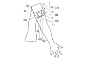
- FIG. 1 is an explanatory view showing a state in which the electrocardiographic measuring device 1 is attached to the user's upper arm 100.
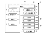
- FIG. 2 is a block diagram showing the configuration of the electrocardiographic measuring device 1.
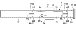
- FIG. 3 is a plan view showing the configuration of the electrocardiographic measuring device 1.
- FIG. 3 shows a state in which the belt 11 of the electrocardiographic measuring device 1 is unfolded.
- FIG. 4 is a perspective view showing the configuration of the electrocardiographic measuring device 1.
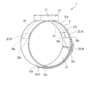
- FIG. 5 is a cross-sectional view schematically showing a state in which the electrocardiographic measuring device 1 is attached to the upper arm 100.
- the electrocardiographic measuring device 1 is a potential measuring device that is attached to a living body, detects potentials at a plurality of locations on the surface of the skin of the living body, and generates electrocardiographic information necessary for generating an electrocardiogram based on the detected voltages. ..
- the electrocardiogram measuring device 1 may generate and display an electrocardiogram waveform, or may be configured to display information necessary for generating an electrocardiogram and output it to an external terminal.
- the electrocardiographic measuring device 1 includes a belt 11 and a device main body 12.
- the belt 11 and the device main body 12 are integrally formed.
- the electrocardiographic measuring device 1 functions as a so-called wearable device that is attached to the upper arm 100 as a living body by, for example, a belt 11.
- FIG. 1 shows an example of a state in which the electrocardiographic measuring device 1 is attached to the upper arm 100 of the person to be measured.
- the electrocardiographic measuring device 1 may be configured such that the belt 11 and the device main body 12 are separately configured and connected via a signal line or the like.
- the belt 11 holds the device main body 12.
- the belt 11 is wrapped around the upper arm 100.
- the belt 11 includes a belt main body 21, an electrode array 22, a fixing means 23, and a wiring portion 24.
- the belt body 21 is made of, for example, a flexible resin or fiber.
- the belt body 21 is set to a length that can be worn on the upper arm 100 of the person to be measured who wears the electrocardiographic measuring device 1.
- the belt body 21 is formed in a long strip shape in one direction.
- the electrode array 22 is electrically connected to the control board 40 described later of the apparatus main body 12 via the wiring unit 24.
- the electrode array 22 includes a plurality of electrodes 33 and a ground electrode 34.
- the plurality of electrodes 33 are provided on the other main surface 21b of the belt body 21.
- the plurality of electrodes 33 are arranged apart from each other in the longitudinal direction of the belt body 21.
- the plurality of electrodes 33 are electrically connected to the electrocardiographic information generation unit 45, which will be described later, by the wiring unit 24. In other words, the plurality of electrodes 33 are electrically connected to the control substrate 40.
- the plurality of electrodes 33 are, for example, two electrodes 33.
- the electrodes 33 are provided on the belt main body 21 and are arranged in the lateral direction of the belt main body 21, and the belt main body 21 is wound around the upper arm 100 to form a plurality of electrode pieces 33a whose postures can be changed according to the upper arm 100.
- a signal line 33b for connecting a plurality of electrode pieces 33a in series is provided.
- the plurality of electrode pieces 33a are made of a conductive material.
- the plurality of electrode pieces 33a are fixed to the belt body 21.
- the plurality of electrode pieces 33a are formed, for example, in the same shape and the same size.
- the electrode piece 33a is formed, for example, in the shape of a rectangular plate.
- the main surface of the electrode piece 33a on the upper arm side is formed, for example, as a flat surface.
- the plurality of electrode pieces 33a are fixed to the belt body 21 in a posture in which two sides are parallel to the lateral direction of the belt body 21, for example. Further, in the plurality of electrode pieces 33a, two sides of the belt body 21 along the lateral direction are arranged in a straight line.
- the length of the electrode piece 33a along the short side of the belt body 21 is the sum of the lengths of the plurality of electrode pieces 33a along the short side of the belt body 21 and the length along the short side of the belt body 21. The length is set to be as close as possible.
- a gap is provided between the two electrode pieces 33a arranged adjacent to each other in the lateral direction of the belt body 21 so that the two electrode pieces 33a can be displaced according to the upper arm 100.
- the plurality of electrodes 33 configured in this way may be configured to be detachable from, for example, the belt body 21.
- the signal line 33b connects a plurality of electrode pieces 33a in series.
- the signal line 33b is connected to one electrode piece 33a and the other electrode piece 33a.
- the signal line 33b may be provided in the belt main body 21, for example.
- the ground electrode 34 is provided on the other main surface 21b of the belt body 21.
- the ground electrode 34 is electrically connected to the electrocardiographic information generation unit 45 via the wiring unit 24.
- the ground electrode 34 is electrically connected to the control substrate 40.
- the ground electrode 34 configured in this way may be detachably configured to be attached to or detached from the belt body 21, for example.
- the wiring unit 24 electrically connects the plurality of electrodes 33 and the electrocardiographic information generation unit 45. Further, the wiring unit 24 electrically connects the ground electrode 34 and the electrocardiographic information generation unit 45.
- the fixing means 23 is configured so that the belt body 21 can be fixed to the upper arm 100 in a state where the plurality of electrodes 33 are brought into contact with the upper arm 100 and the belt body 21 is wound around the user's upper arm 100.
- the fixing means 23 includes, for example, a belt fixing ring 36 and a hook-and-loop fastener 37.
- the belt fixing ring 36 is provided at one end in the longitudinal direction of the belt body 21.
- the belt fixing ring 36 is formed in an annular shape into which the belt body 21 can be inserted.
- the hook-and-loop fastener 37 includes a loop 37a and a hook 37b.
- the loop 37a is provided on one main surface 21a of the belt body 21.
- the loop 37a is provided on the main surface 21a in a region facing the other end of the belt body 21 folded back by, for example, the belt fixing ring 36.
- the region of the main surface 21a facing the other end of the belt body 21 is the belt body regardless of the expected circumference of the user's upper arm 100 from the minimum length to the maximum length.
- the size is set so as to face the other end of 21.
- the hook 37b is provided at the other end of the main surface 21a of the belt body 21.
- the wiring unit 24 is composed of, for example, a lead wire embedded in the belt body 21. Further, the wiring portion 24 may be composed of a flexible substrate provided on the main surface 21b of the belt main body 21.
- the apparatus main body 12 includes a case 41, an operation unit 42, a display unit 43, a power supply unit 44, an electrocardiographic information generation unit 45, an electrocardiogram generation unit 46, and a memory. 47 and a control unit 48 are provided.
- the electrocardiographic information generation unit 45, the electrocardiogram generation unit 46, and the control unit 48 are provided on, for example, the control board 40.
- the control board 40 is housed in the case 41.
- the operation unit 42 and the display unit 43 are provided on, for example, the control board 40.
- the device main body 12 includes a communication unit that transmits / receives information to / from an external terminal.
- the communication unit transmits / receives information to / from an external terminal wirelessly and / or by wire. This communication unit is provided on, for example, the control board 40.
- the case 41 accommodates a part of the operation unit 42, a part of the display unit 43, an electrocardiographic information generation unit 45, an electrocardiogram generation unit 46, a memory 47, and a control unit 48. Further, the case 41 exposes a part of the operation unit 42 and a part of the display unit 43 from the outer surface.
- the case 41 is fixed to the belt 11.
- the operation unit 42 inputs a command from the user.
- the operation unit 42 includes a plurality of buttons 42a and sensors that detect the operation of the buttons 42a.
- the operation unit 42 may include a pressure-sensitive touch panel, a capacitive touch panel, or the like, a microphone that receives a sound command, or the like provided on the case 41, the display unit 43, or the like.
- the operation unit 42 converts a command into an electric signal and outputs the electric signal to the control unit 48 when the user operates the operation unit 42.
- the display unit 43 is electrically connected to the control unit 48.
- the display unit 43 is, for example, a liquid crystal display (LCD: Liquid Crystal Display) or an organic electroluminescence display (OELD: Organic Electro Luminescence Display).
- the display unit 43 displays the date and time, electrocardiographic information, electrocardiogram waveform, and the like according to the control signal from the control unit 48.
- the display unit 43 displays various information including blood pressure values such as the displayed systolic blood pressure and diastolic blood pressure and measurement results such as heart rate. May be displayed.
- the power supply unit 44 is a power source.
- the power supply unit 44 is a secondary battery such as a lithium ion battery, for example.
- the power supply unit 44 is electrically connected to the control unit 48.
- the power supply unit 44 supplies power to the control unit 48.
- the power supply unit 44 supplies driving power to the operation unit 42, the display unit 43, the electrocardiographic information generation unit 45, the electrocardiogram generation unit 46, and the memory 47 via the control unit 48 and the control unit 48.
- the electrocardiographic information generation unit 45 is electrically connected to a plurality of electrodes 33 of the electrode array 22, two electrodes 33 in this embodiment, for example, via a wiring unit 24.
- the electrocardiographic information generation unit 45 calculates the potential difference from the voltages detected by the two electrodes 33 and generates electrocardiographic information.
- the electrocardiogram generation unit 46 is electrically connected to the electrocardiographic information generation unit 45.
- the electrocardiogram generation unit 46 generates electrocardiogram information based on the electrocardiographic information generated by the electrocardiographic information generation unit 45.
- the ECG information may include an ECG waveform.
- Such an electrocardiographic information generation unit 45 and an electrocardiogram generation unit 46 are processing circuits capable of executing the functions of the electrocardiographic information generation unit 45 and the electrocardiogram generation unit 46, respectively.
- the electrocardiographic information generation unit 45 and the electrocardiogram generation unit 46 are electrically connected to the control unit 48.
- the control unit 48 includes the processing circuits of the electrocardiographic information generation unit 45 and the electrocardiogram generation unit 46, and executes the program stored in the memory 47 to perform the functions of the electrocardiographic information generation unit 45 and the electrocardiogram generation unit 46. You may do it.
- the electrocardiographic information generation unit 45 or the electrocardiogram generation unit 46 may have a low-pass filter, an amplifier, and an analog / digital converter.
- a potential difference signal is converted into a digital signal by an analog / digital converter after removing unnecessary noise components with a low-pass filter and then amplifying the signal with an amplifier.
- the memory 47 includes, for example, SSD (Solid State Drive), RAM (Random Access Memory), ROM (Read Only Memory), and the like as storage media.
- the memory 47 stores a program necessary for executing various control processes. Further, the memory 47 stores the detected electrocardiographic signal, the generated electrocardiographic information, the electrocardiogram information, and the like. Further, for example, the memory 47 stores such information in chronological order.
- the control unit 48 includes a single processor or a plurality of processors.
- the control unit 48 is formed by one or more processing circuits.
- the control unit 48 is, for example, a CPU (Central Processing Unit).
- the control unit 48 executes the entire operation of the electrocardiographic measuring device 1 and a predetermined operation (function) based on the program stored in the memory 47.
- the control unit 48 executes a predetermined calculation, analysis, processing, or the like according to the read program.
- the control unit 48 controls the operation of the operation unit 42, the display unit 43, the electrocardiographic information generation unit 45, and the electrocardiogram generation unit 46, transmits / receives signals, and supplies electric power.
- the person to be measured winds the belt body 21 around the upper arm 100 with the main surface 21b of the belt body 21 facing the upper arm 100 of the person to be measured, and the other end of the belt body 21 is passed through the belt fixing ring 36 to the belt fixing ring 36. Wrap at.
- the person to be measured then tightens the belt body 21 against the upper arm 100 by pulling the other end of the belt body 21.
- the person to be measured next fixes the hook 37b provided at the other end of the belt body 21 to the loop 37a provided on the belt body 21.
- the electrocardiographic measuring device 1 is attached to the upper arm of the person to be measured. Then, the person to be measured controls each configuration by operating the operation unit 42, and detects the electrocardiographic signal via the two electrodes 33. Then, the electrocardiographic information generation unit 45 generates electrocardiographic information from the electrocardiographic signal, and the electrocardiogram generation unit 46 generates electrocardiographic information from the electrocardiographic information.
- the control unit 48 stores the electrocardiographic information and the electrocardiogram information in the memory 47, and displays information such as the date and time and the electrocardiogram on the display unit 43. Further, the control unit 48 may control the communication unit to transmit various information such as date and time, electrocardiographic information, and electrocardiogram information to an external terminal.
- the belt body 21 is wound around the upper arm 100, so that the plurality of electrode pieces 33a of the plurality of electrodes 33 are arranged with the plurality of electrode pieces 33a of the upper arm 100.
- the posture changes according to the part.
- the surface of the electrode 33 on the upper arm 100 side which is composed of the surface of the plurality of electrode pieces 33a on the upper arm 100 side, changes following the upper arm 100. Therefore, the electrode 33 is in close contact with the upper arm 100. Since the electrode 33 is in close contact with the upper arm 100, the electrocardiographic measuring device 1 can suitably detect the voltage generated on the surface of the upper arm 100. As a result, the electrocardiographic measuring device 1 can measure the electrocardiogram waveform more accurately.
- the plurality of electrode pieces 33a are formed to have the same shape and the same size. Therefore, the manufacturing cost of the electrode 33 can be reduced.
- each of the plurality of electrodes 33 includes a plurality of electrode pieces 33a. Therefore, the plurality of electrodes 33 can be brought into close contact with the upper arm 100.
- the electrode 33 has a configuration including a plurality of electrode pieces 33a, and a configuration including two electrode pieces 33a has been described as an example, but the present invention is not limited to this.
- the electrode 33 may have a configuration including three or more electrode pieces 33a as in the modified examples shown in FIGS. 6 and 7.
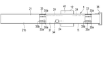
- FIG. 6 is a plan view showing the configuration of an electrocardiographic measuring device 1 in which the electrodes 33 include five electrode pieces 33a as an example.
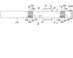
- FIG. 7 is a cross-sectional view schematically showing a state in which the electrocardiographic measuring device 1 is attached to the user's upper arm 100.
- the configuration in which the plurality of electrode pieces 33a of the electrodes 33 are formed to have the same size has been described as an example, but the present invention is not limited to this.
- at least one of the plurality of electrode pieces 33a may be formed in a different shape and a different size as compared with the others.
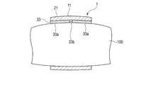
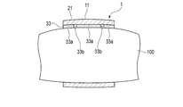
- FIGS. 8 and 9 An example of a configuration in which at least one of the plurality of electrode pieces 33a is formed to have a different size as compared with the others will be described with reference to FIGS. 8 and 9.
- the electrodes 33 include three electrode pieces 33a
- the two electrode pieces 33a arranged at both ends in the lateral direction of the belt main body 21 are oriented in the lateral direction of the belt main body 21.
- the length along the three electrode pieces 33a is shorter than the length along the short side of the belt body 21 of the electrode piece 33a arranged at the center in the short side direction of the belt body 21.
- the length of the two electrode pieces 33a arranged at both ends in the lateral direction of the belt main body 21 among the three electrode pieces 33a along the lateral direction of the belt main body 21 is the lateral direction of the belt main body 21.
- both ends of the belt body 21 of the electrode 33 are separated from the upper arm 100 in the lateral direction.
- both ends of the electrode 33 are formed of the electrode pieces 33a in the lateral direction, the electrode 33 can be brought into close contact with the upper arm 100 of the electrode 33.
- each of the plurality of electrodes 33 includes a plurality of electrode pieces 33a
- the present invention is not limited to this.
- Each one or more of the plurality of electrodes 33 may be configured to include a plurality of electrode pieces 33a.
- one of the three electrodes 33 may be composed of one member.
- FIG. 10 shows, as an example, an electrocardiographic measuring device 1 having a configuration in which electrodes 33 include four electrode pieces 33a, and these four electrode pieces 33a are arranged in two rows of two in each of the short sides of the belt body 21. Is shown. Then, these four electrode pieces 33a are connected in series by a signal line 33b.
- the configuration in which the two electrodes 33 are provided has been described as an example, but the present invention is not limited to this. In another example, three or more electrodes 33 may be provided.
- the electrocardiographic measuring device 1 has been described by using an example in which the belt 11 is attached to the upper arm, but the electrocardiographic measuring device 1 may be attached to the chest or other parts of the living body.
- the belt 11 may have a configuration used in a biometric information measuring device provided for electrocardiographic measurement and blood pressure measurement.
- the biological information measuring device produces a blood pressure measuring function of generating a blood pressure value from the pulse wave sensor and the pulse wave information detected by the pulse wave sensor. It may be configured to have a processing circuit or the like.
- Such a biological information measuring device exerts a blood pressure measurement function of calculating a pulse wave propagation time (PTT) for each heartbeat, estimating blood pressure, and measuring a blood pressure value.
- PTT pulse wave propagation time
- such a biological information measuring device is, for example, a pulse for each heartbeat, which is one of the feature quantities from the R wave peak RP detected by the electrocardiographic signal and the pulse wave signal detected by the pulse wave sensor.
- the pulse wave propagation time (PTT) for each heartbeat is calculated based on the time difference from the wave rising PS.
- the present invention can constitute various inventions by an appropriate combination of a plurality of constituent elements disclosed in each of the above embodiments. For example, some components may be removed from all the components shown in each embodiment. In addition, components from different embodiments may be combined as appropriate.
- Electrocardiographic measuring device 11 ... Belt 12 ... Device main body 21 ... Belt main body 21a ... Main surface 21b ... Main surface 22 ... Electrode array 23 ... Fixing means 24 ... Wiring part 33 ... Electrode 33a ... Electrode piece 33b ... Signal line 34 ... Ground electrode 36 ... Belt fixing ring 37 ... Surface fastener 37a ... Loop 37b ... Hook 41 ... Case 42 ... Operation unit 42a ... Button 43 ... Display unit 44 ... Power supply unit 45 ... Electrocardiographic information generation unit 46 ... Electrocardiogram generation unit 47 ... Memory 48 ... Control unit 100 ... Upper arm
Abstract
電極が上腕に密着できるベルト、及び、心電測定装置を提供すること。 ベルト(11)は、帯状に形成されるベルト本体(21)と、ベルト本体(21)の主面(21b)に設けられてベルト本体(21)の短手方向に並び、信号線(33b)により直列に接続される複数の電極片(33a)を備える電極(33)と、を備える。
Description
本発明は、心臓の動きに起因して生じる生体の表面の電位に応じた生体信号の測定に用いられるベルト及び心電測定装置に関する。
生体信号の一つとして、心臓の動きに起因して生じる生体の表面に生じる電圧である心電信号を検出し、ユーザの心電図波形を生成する心電計測装置が知られている。
このような心電計測装置としては、ユーザの上腕に巻き付けるベルト本体と、このベルト本体の内面に長手方向に等間隔で固定された複数の電極と、を有するベルトを用いる心電測定装置が知られている(例えば、特許文献1参照)。
上述した心電測定装置では、心電信号の検出強度を高める為に、電極の生体に接触する面積が大きいことが好ましい。この為、電極の上腕に接触する面の面積を大きくすることが考えられ、例えば、電極をベルトの短手方向で一端から他端までの範囲で極力大きい形状に形成することが考えられる。
しかしながら、生体の表面は曲面に構成される。この為、電極の生体側の面の面積を大きくすると、電極の生体に接触しない領域が大きくなる。すなわち、電極の生体に対する密着度が低下する。
そこで本発明は、電極の生体に密着できるベルト、及び、心電測定装置を提供することを目的とする。
一態様によれば、ベルトは、帯状に形成されるベルト本体と、前記ベルト本体の一方の主面に設けられて前記ベルト本体の短手方向に並び、信号線により直列に接続される複数の電極片を備える電極と、を備える。
この態様によれば、ベルト本体が生体に巻き付けられることで、複数の電極片が、当該複数の電極片が対向する生体の表面にならう。すなわち、複数の電極片の姿勢が、生体の表面にならって変化する。さらに換言すると、複数の電極片の生体側の面により構成される電極の生体側の面が、生体にならう。この為、電極が生体に密着する。
上記一態様のベルトにおいて、前記複数の電極片の、前記短手方向に沿う長さは等しい、ベルトが提供される。
この態様によれば、同形状及び同じ大きさの電極片により電極を構成できるので、電極の製造コストを低減できる。
上記一態様のベルトにおいて、前記複数の電極片は、3つの電極片であり、前記複数の電極片のうち、前記短手方向で両端に配置される電極片の前記短手方向に沿う長さは、前記3つの電極片のうち前記短手方向で中央に配置される電極片の前記短手方向に沿う長さに比較して短い、ベルトが提供される。
この態様によれば、電極が備える電極片の個数が多くなることを防止しつつ、生体に密着しにくい電極のベルト本体の短手方向で両端側を生体に密着できる。さらに、電極片の数が多くなることを防止できることで、信号線を少なくできるので、信号線により生じるノイズを小さくできる。
上記一態様のベルトにおいて、前記電極は、複数設けられる、ベルトを提供できる。
この態様によれば、複数の電極を生体に密着できる。
一態様によれば、上記一態様のベルトと、制御基板を内蔵する装置本体と、前記ベルト本体に設けられ、前記制御基板及び前記電極を電気的に接続する配線部と、を備える、心電測定装置が提供される。
この態様によれば、ベルト本体が生体に巻き付けられることで、複数の電極片が、当該複数の電極片が対向する生体の表面にならう。すなわち、複数の電極片の姿勢が、生体の表面にならって変化する。さらに換言すると、複数の電極片の生体側の面により構成される電極の生体側の面が、生体にならう。この為、電極が生体に密着する。電極が生体に密着することから、心電測定装置は、生体の表面に生じる電圧を好適に検出することが可能となり、心電図波形をより正確に計測できる。
本発明は、電極を生体に密着できるベルト、及び、心電測定装置を提供することができる。
以下、本発明の一実施形態に係る心電測定装置1の一例について、図1乃至図5を用いて説明する。
図1は、心電測定装置1をユーザの上腕100に装着した状態を示す説明図である。図2は、心電測定装置1の構成を示すブロック図である。図3は、心電測定装置1の構成を示す平面図である。図3は、心電測定装置1のベルト11を展開した状態を示している。図4は、心電測定装置1の構成を示す斜視図である。図5は、心電測定装置1を上腕100に装着した状態を模式的に示す断面図である。
心電測定装置1は、生体に装着され、生体の皮膚の表面の複数箇所の電位を検出し、これら検出した電圧に基づいて心電図の生成に必要な心電情報を生成する電位測定装置である。なお、心電測定装置1は、心電図波形を生成し、表示してもよく、心電図の生成に必要な情報を表示し、外部の端末に出力する構成であってもよい。
図1乃至図3に示すように、心電測定装置1は、ベルト11と、装置本体12と、を備える。心電測定装置1は、例えば、ベルト11及び装置本体12が一体に形成される。心電測定装置1は、例えば、ベルト11によって、生体としての上腕100に装着される、所謂ウェアラブルデバイスとして機能する。図1は心電測定装置1が被測定者の上腕100に装着された状態の一例を示す。なお、心電測定装置1は、ベルト11及び装置本体12が別体に構成され、信号線等を介して接続される構成であってもよい。
ベルト11は、装置本体12を保持する。ベルト11は、上腕100に巻き付けられる。図3及び図4に示すように、ベルト11は、ベルト本体21と、電極アレイ22と、固定手段23と、配線部24と、を備える。
ベルト本体21は、例えば柔軟性を有する樹脂または繊維により構成される。ベルト本体21は、心電測定装置1を装着する被測定者の上腕100に装着できる長さに設定される。ベルト本体21は、一方向に長い帯状に形成される。ベルト本体21は、心電測定装置1を上腕100に装着したときに、外側の面である表面に装置本体12が固定され、生体側の面である裏面に電極アレイ22が設けられる。
電極アレイ22は、配線部24を介して、装置本体12の後述する制御基板40に電気的に接続される。電極アレイ22は、複数の電極33と、グランド電極34と、を備える。
複数の電極33は、ベルト本体21の他方の主面21bに設けられる。複数の電極33は、ベルト本体21の長手方向に離間して配置される。複数の電極33は、配線部24により、後述する心電情報生成部45に電気的に接続される。換言すると、複数の電極33は、制御基板40に電気的に接続される。複数の電極33は、一例として、2つの電極33である。
電極33は、ベルト本体21に設けられてベルト本体21の短手方向に並び、ベルト本体21が上腕100に巻き付けられることで、上腕100にならって姿勢が変化可能な複数の電極片33aと、複数の電極片33aを直列に接続する信号線33bと、を備える。
複数の電極片33aは、導電性材料がから構成される。複数の電極片33aは、ベルト本体21に固定される。複数の電極片33aは、例えば、同じ形状でかつ同じ大きさに形成される。電極片33aは、例えば、矩形板状に形成される。電極片33aの、上腕側の主面は、例えば、平面に構成される。
複数の電極片33aは、例えば、2辺がベルト本体21の短手方向に平行となる姿勢で、ベルト本体21に固定される。また、複数の電極片33aは、ベルト本体21の短手方向に沿う2辺が、直線状に並ぶ。電極片33aのベルト本体21の短手方向に沿う長さは、複数の電極片33aのベルト本体21の短手方向に沿う長さの和が、ベルト本体21の短手方向に沿う長さに極力近い値となる長さに設定される。
ベルト本体21の短手方向に隣接配置される2つの電極片33aの間には、これら2つの電極片33aを、上腕100にならって変位可能とする隙間が設けられる。
このように構成される複数の電極33は、例えば、ベルト本体21に対して着脱可能に構成されてもよい。
信号線33bは、複数の電極片33aを直列に接続する。本実施形態では、信号線33bは、一方の電極片33a及び他方の電極片33aに接続される。信号線33bは、例えば、ベルト本体21内に設けられてもよい。
グランド電極34は、ベルト本体21の他方の主面21bに設けられる。グランド電極34は、配線部24を介して、心電情報生成部45に電気的に接続される。換言すると、グランド電極34は、制御基板40に電気的に接続される。このように構成されるグランド電極34は、例えば、ベルト本体21に着脱可能に構成されてもよい。
配線部24は、複数の電極33、及び、心電情報生成部45を電気的に接続する。また、配線部24は、グランド電極34、及び、心電情報生成部45を電気的に接続する。
固定手段23は、複数の電極33を上腕100に接触させてベルト本体21をユーザの上腕100に巻き付けた状態で、ベルト本体21を上腕100に固定可能に構成される。固定手段23は、例えば、ベルト固定リング36と、面ファスナ37と、を備える。
ベルト固定リング36は、ベルト本体21の長手方向で一端に設けられる。ベルト固定リング36は、ベルト本体21を挿入可能な環状に形成される。
面ファスナ37は、ループ37aと、フック37bと、を備える。ループ37aは、ベルト本体21の一方の主面21aに設けられる。ループ37aは、主面21aの、例えばベルト固定リング36で折り返されたベルト本体21の他端部と対向する領域に設けられる。
ここで、主面21aのベルト本体21の他端部と対向する領域は、想定されるユーザの上腕100の周長が最小長さから最大長さのいずれの周長であっても、ベルト本体21の他端部と対向する大きさに設定される。フック37bは、ベルト本体21の主面21aの他端部に設けられる。
配線部24は、例えば、ベルト本体21内に埋め込まれるリード線により構成される。また、配線部24は、ベルト本体21の主面21bに設けられるフレキシブル基板により構成されてもよい。
装置本体12は、図1乃至図3に示すように、ケース41と、操作部42と、表示部43と、電力供給部44と、心電情報生成部45と、心電図生成部46と、メモリ47と、制御部48と、を備えている。
心電情報生成部45、心電図生成部46、及び、制御部48は、例えば、制御基板40に設けられている。制御基板40は、ケース41内に収容される。また、操作部42及び表示部43は、例えば制御基板40に設けられている。また、装置本体12は、外部の端末との情報の送受信を行う通信部を含む。なお、通信部は、外部の端末と無線及び/又は有線により情報の送受信を行う。この通信部は、例えば、制御基板40に設けられている。
心電情報生成部45、心電図生成部46、及び、制御部48は、例えば、制御基板40に設けられている。制御基板40は、ケース41内に収容される。また、操作部42及び表示部43は、例えば制御基板40に設けられている。また、装置本体12は、外部の端末との情報の送受信を行う通信部を含む。なお、通信部は、外部の端末と無線及び/又は有線により情報の送受信を行う。この通信部は、例えば、制御基板40に設けられている。
ケース41は、操作部42の一部、表示部43の一部、心電情報生成部45、心電図生成部46、メモリ47、制御部48を収容する。また、ケース41は操作部42の一部及び表示部43の一部を外面から露出させる。ケース41は、ベルト11に固定される。
操作部42は、使用者からの指令を入力する。例えば、操作部42は、複数の釦42a及び釦42aの操作を検出するセンサを含む。なお、操作部42は、ケース41や表示部43等に設けられた、感圧式や静電容量式等のタッチパネル、音による指令を受け付けるマイクロフォン等を含んでいてもよい。操作部42は、使用者が操作することで、指令を電気信号に変換し、該電気信号を制御部48へ出力する。
表示部43は、電気的に制御部48に接続される。表示部43は、例えば、液晶ディスプレイ(LCD:Liquid Crystal Display)又は有機エレクトロルミネッセンスディスプレイ(OELD:Organic Electro Luminescence Display)である。表示部43は、制御部48からの制御信号に従って、日時や心電情報、心電図波形等を表示する。なお、心電測定装置1が血圧値を表示する生体情報測定装置に用いられる場合には、表示部43は、表示最高血圧及び最低血圧などの血圧値や心拍数等の測定結果を含む各種情報を表示してもよい。
電力供給部44は、電源である。電力供給部44は、例えば、リチウムイオンバッテリ等の二次電池である。電力供給部44は、制御部48に電気的に接続される。具体例として、電力供給部44は、制御部48に電力を供給する。電力供給部44は、制御部48、並びに、制御部48を介して操作部42、表示部43、心電情報生成部45、心電図生成部46、メモリ47に、駆動用の電力を供給する。
心電情報生成部45は、電極アレイ22の複数の電極33、本実施形態では2個の電極33に、例えば配線部24を介して電気的に接続される。心電情報生成部45は、2個の電極33で検出された電圧から電位差を算出して心電情報を生成する。
心電図生成部46は、心電情報生成部45に電気的に接続される。心電図生成部46は、心電情報生成部45が生成した心電情報に基づいて、心電図の情報を生成する。この心電図の情報には、心電図波形が含まれていてもよい。
このような心電情報生成部45及び心電図生成部46は、例えば、心電情報生成部45及び心電図生成部46の機能をそれぞれ実行できる処理回路である。心電情報生成部45及び心電図生成部46は、制御部48に電気的に接続される。なお、制御部48が心電情報生成部45及び心電図生成部46の処理回路を含み、メモリ47に記憶されたプログラムを実行することで、心電情報生成部45及び心電図生成部46の機能を実行してもよい。
また、例えば、心電情報生成部45又は心電図生成部46は、ローパスフィルタ、増幅器及びアナログ/デジタル変換器を有していてもよい。例えば、電位差の信号を、ローパスフィルタで不要なノイズ成分を除去し、さらに増幅器で増幅した後アナログ/デジタル変換器でデジタル信号に変換する。
メモリ47は、例えば、記憶媒体としてSSD(Solid State Drive)、RAM(Random Access Memory)およびROM(Read Only Memory)等を含む。メモリ47は、各種制御処理を実行するために必要なプログラムを格納する。また、メモリ47は、検出した心電信号、生成した心電情報及び心電図情報等を記憶する。また、例えば、メモリ47には、これら情報が時系列に従い記憶される。
制御部48は、単数又は複数のプロセッサを含む。制御部48は、一以上の処理回路により形成される。制御部48は、例えば、CPU(Central Processing Unit)である。制御部48は、メモリ47に格納されたプログラムに基づいて心電測定装置1の全体の動作及び所定の動作(機能)を実行させる。制御部48は、読み込んだプログラムに従い、所定の演算、解析、処理等を実行する。制御部48は、操作部42、表示部43、心電情報生成部45及び心電図生成部46の動作の制御、信号の送受信、及び電力の供給を行う。
このように構成された心電測定装置1の上腕100への装着の一例を説明する。例えば被測定者は、ベルト本体21の主面21bを被測定者の上腕100に向けてベルト本体21を上腕100に巻き付け、ベルト本体21の他端部を、ベルト固定リング36を通してベルト固定リング36で折り返す。被測定者は、次に、ベルト本体21の他端部を引っ張ることでベルト本体21を上腕100に対して締め付ける。被測定者は、次に、ベルト本体21の他端部に設けられるフック37bを、ベルト本体21に設けられるループ37aに固定する。
これにより、心電測定装置1が被測定者の上腕に装着される。そして、被測定者は、操作部42を操作することで、制御部48が各構成を制御し、2個の電極33を介して心電信号を検出する。そして、心電情報生成部45が心電信号から心電情報を生成し、心電図生成部46が心電情報から心電図情報を生成する。制御部48が心電情報及び心電図情報をメモリ47に記憶するとともに、表示部43に日時や心電図等の情報を表示する。また、制御部48は、通信部を制御して日時、心電情報及び心電図情報等の各種情報を外部の端末に送信しても良い。
このように構成される心電測定装置1では、ベルト本体21が上腕100に巻き付けられることで、複数の電極33のそれぞれの複数の電極片33aは、上腕100の複数の電極片33aが配される部分にならって姿勢が変化する。換言すると、複数の電極片33aの上腕100側の面により構成される電極33の上腕100側の面が、上腕100にならって変化する。この為、電極33が上腕100に密着する。電極33が上腕100に密着することから、心電測定装置1は、上腕100の表面に生じる電圧を好適に検出することが可能となる。結果、心電測定装置1は、心電図波形をより正確に計測できる。
さらに、複数の電極片33aは、同形状でかつ同じ大きさに形成される。この為、電極33の製造コストを低減できる。
さらに、複数の電極33は、それぞれ、複数の電極片33aを備える。この為、複数の電極33を上腕100に密着することが可能となる。
なお、上述の例では、電極33は、複数の電極片33aを備える構成として、2つの電極片33aを備える構成が一例として説明されたが、これに限定されない。他の例では、電極33は、図6及び図7に示す変形例のように、3つ以上の電極片33aを備える構成であってもよい。図6は、一例として、電極33が5つの電極片33aを備える心電測定装置1の構成を示す平面図である。図7は、心電測定装置1がユーザの上腕100に装着された状態を模式的に示す断面図である。
また、上述の例では、電極33の複数の電極片33aは、同じ大きさに形成される構成が一例として説明されたが、これに限定されない。他の例では、複数の電極片33aは、少なくとも1つが他に比較して異なる形状及び異なる大きさに形成されてもよい。
複数の電極片33aの少なくとも1つが他に比較して異なる大きさに形成される構成の一例を、図8及図9を用いて説明する。図8及び図9に示すように電極33が3つの電極片33aを備える構成の場合、ベルト本体21の短手方向で両端に配置される2つ電極片33aのベルト本体21の短手方向に沿う長さは、3つの電極片33aのうちベルト本体21の短手方向で中央に配置される電極片33aのベルト本体21の短手方向に沿う長さに比較して短い。
このように、3つの電極片33aのうちベルト本体21の短手方向で両端に配置される2つの電極片33aのベルト本体21の短手方向に沿う長さが、ベルト本体21の短手方向で中央に配置される電極片33aのベルト本体21の短手方向の長さに比較して短いことで、電極片33aの数が多くなることを防止しつつ、電極33を上腕100に密着できる。
この効果について、説明する。電極33が1つの部材から構成される場合、電極33のベルト本体21の短手方向で両端側は、上腕100から離れる。しかしながら、電極33の短手方向で両端側が、それぞれ電極片33aで構成されることで、電極33の上腕100に密着できる。
さらに、電極片33aの数が多くなることを防止できることで信号線33bの数が多くなることを防止できるので、電極33が検出するノイズを小さくできる。
また、上述の例では、複数の電極33のそれぞれが、複数の電極片33aを備える構成が一例として説明されたが、これに限定されない。複数の電極33の1つ以上のそれぞれが、複数の電極片33aを備える構成であってもよい。
例えば、複数の電極33として、3つの電極33を備える構成の場合、これら3つの電極33のうち、1つの電極33は、1つの部材から構成されてもよい。
また、上述の例では、電極33の複数の電極片33aは、ベルト本体21の短手方向に一列に並ぶ構成が一例として説明されたが、これに限定されない。他の例では、図10に示すように、複数の電極片33aは、ベルト本体21の短手方向に複数列に並ぶ構成であってもよい。図10は、一例として、電極33が4つの電極片33aを備え、これら4つの電極片33aがベルト本体21の短手方向に2つずつ2列に配置される構成を備える心電測定装置1を示している。そして、これら4つの電極片33aは、信号線33bにより直列に接続される。
また、上述の例では、2つの電極33が設けられる構成が一例として説明されたが、これに限定されない。他の例では、電極33は、3つ以上が設けられてもよい。
さらに、上述した例では、心電測定装置1は、ベルト11が上腕に装着される例を用いて説明したが、胸部や生体の他の部位に装着される構成であってもよい。
また、上述した例では、ベルト11は、心電測定装置1に用いられる構成を説明したがこれに限定されない。例えば、ベルト11は、心電測定及び血圧測定に設けられる生体情報測定装置に用いられる構成であってもよい。具体例として、生体情報測定装置は、上述の心電測定装置1の構成に加え、脈波センサ及び脈波センサで検出された脈波情報から、血圧値を生成する血圧測定の機能を生じさせる処理回路等を有する構成としてもよい。このような生体情報測定装置は、1心拍毎の脈波伝搬時間(PTT)を算出し、血圧推定して血圧値を測定処理する血圧測定の機能を発揮する。なお、このような生体情報測定装置は、例えば、心電信号により検出されたR波ピークRPと、脈波センサで検出された脈波信号からその特徴量の一つである1心拍毎の脈波立ち上がりPSとの間の時間差をもとに、1心拍毎の脈波伝搬時間(PTT)を算出する。
以上、この発明に係る各実施形態について詳細に説明してきたが、前述までの説明はあらゆる点においてこの発明の例示に過ぎず、この発明の範囲を逸脱することなく種々の改良や変形を行うことができることは言うまでもない。つまり、この発明の実施にあたって、各実施形態に応じた具体的構成が適宜採用されてもよい。
また、この発明は、上記各実施形態に開示されている複数の構成要素の適宜な組み合せにより種々の発明を構成できる。例えば、各実施形態に示される全構成要素から幾つかの構成要素を削除してもよい。さらに、異なる実施形態に亘る構成要素を適宜組み合せてもよい。
1…心電測定装置
11…ベルト
12…装置本体
21…ベルト本体
21a…主面
21b…主面
22…電極アレイ
23…固定手段
24…配線部
33…電極
33a…電極片
33b…信号線
34…グランド電極
36…ベルト固定リング
37…面ファスナ
37a…ループ
37b…フック
41…ケース
42…操作部
42a…釦
43…表示部
44…電力供給部
45…心電情報生成部
46…心電図生成部
47…メモリ
48…制御部
100…上腕
11…ベルト
12…装置本体
21…ベルト本体
21a…主面
21b…主面
22…電極アレイ
23…固定手段
24…配線部
33…電極
33a…電極片
33b…信号線
34…グランド電極
36…ベルト固定リング
37…面ファスナ
37a…ループ
37b…フック
41…ケース
42…操作部
42a…釦
43…表示部
44…電力供給部
45…心電情報生成部
46…心電図生成部
47…メモリ
48…制御部
100…上腕
Claims (5)
- 帯状に形成されるベルト本体と、
前記ベルト本体の一方の主面に設けられて前記ベルト本体の短手方向に並び、信号線により直列に接続される複数の電極片を備える電極と、
を備えるベルト。 - 前記複数の電極片の、前記短手方向に沿う長さは等しい、請求項1に記載のベルト。
- 前記複数の電極片は、3つの電極片であり、
前記複数の電極片のうち、前記短手方向で両端に配置される電極片の前記短手方向に沿う長さは、前記3つの電極片のうち前記短手方向で中央に配置される電極片の前記短手方向に沿う長さに比較して短い、
請求項1に記載のベルト。 - 前記電極は、複数設けられる、請求項1に記載のベルト。
- 請求項1乃至請求項4のいずれか1項に記載のベルトと、
制御基板を内蔵する装置本体と、
前記ベルト本体に設けられ、前記制御基板及び前記電極を電気的に接続する配線部と、
を備える心電測定装置。
Priority Applications (3)
| Application Number | Priority Date | Filing Date | Title |
|---|---|---|---|
| CN202180017523.5A CN115243614A (zh) | 2020-03-31 | 2021-03-01 | 带及心电测定装置 |
| DE112021000615.0T DE112021000615T5 (de) | 2020-03-31 | 2021-03-01 | Manschette und elektrokardiographische messvorrichtung |
| US17/934,920 US20230012616A1 (en) | 2020-03-31 | 2022-09-23 | Belt and electrocardiographic measurement device |
Applications Claiming Priority (2)
| Application Number | Priority Date | Filing Date | Title |
|---|---|---|---|
| JP2020-062874 | 2020-03-31 | ||
| JP2020062874A JP7404975B2 (ja) | 2020-03-31 | 2020-03-31 | ベルト、及び、心電測定装置 |
Related Child Applications (1)
| Application Number | Title | Priority Date | Filing Date |
|---|---|---|---|
| US17/934,920 Continuation US20230012616A1 (en) | 2020-03-31 | 2022-09-23 | Belt and electrocardiographic measurement device |
Publications (1)
| Publication Number | Publication Date |
|---|---|
| WO2021199825A1 true WO2021199825A1 (ja) | 2021-10-07 |
Family
ID=77928139
Family Applications (1)
| Application Number | Title | Priority Date | Filing Date |
|---|---|---|---|
| PCT/JP2021/007617 WO2021199825A1 (ja) | 2020-03-31 | 2021-03-01 | ベルト、及び、心電測定装置 |
Country Status (5)
| Country | Link |
|---|---|
| US (1) | US20230012616A1 (ja) |
| JP (1) | JP7404975B2 (ja) |
| CN (1) | CN115243614A (ja) |
| DE (1) | DE112021000615T5 (ja) |
| WO (1) | WO2021199825A1 (ja) |
Families Citing this family (1)
| Publication number | Priority date | Publication date | Assignee | Title |
|---|---|---|---|---|
| PL439675A1 (pl) * | 2021-11-29 | 2023-06-05 | Demedar Spółka Z Ograniczoną Odpowiedzialnością | Elektrokardiograficzne urządzenie naramienne i sposób pomiaru sygnału elektrokardiograficznego |
Citations (4)
| Publication number | Priority date | Publication date | Assignee | Title |
|---|---|---|---|---|
| JPS57187505U (ja) * | 1981-05-27 | 1982-11-29 | ||
| JP2008086361A (ja) * | 2006-09-29 | 2008-04-17 | Casio Comput Co Ltd | 生体情報検出装置 |
| JP2018121700A (ja) * | 2017-01-30 | 2018-08-09 | Simplex Quantum株式会社 | 心電センサ、心電データ管理システム、及び車両管理システム |
| JP2019136055A (ja) * | 2018-02-06 | 2019-08-22 | Nok株式会社 | 生体測定電極装置 |
Family Cites Families (1)
| Publication number | Priority date | Publication date | Assignee | Title |
|---|---|---|---|---|
| JP5428889B2 (ja) | 2010-01-21 | 2014-02-26 | セイコーエプソン株式会社 | 心電計測装置 |
-
2020
- 2020-03-31 JP JP2020062874A patent/JP7404975B2/ja active Active
-
2021
- 2021-03-01 DE DE112021000615.0T patent/DE112021000615T5/de active Pending
- 2021-03-01 WO PCT/JP2021/007617 patent/WO2021199825A1/ja active Application Filing
- 2021-03-01 CN CN202180017523.5A patent/CN115243614A/zh active Pending
-
2022
- 2022-09-23 US US17/934,920 patent/US20230012616A1/en active Pending
Patent Citations (4)
| Publication number | Priority date | Publication date | Assignee | Title |
|---|---|---|---|---|
| JPS57187505U (ja) * | 1981-05-27 | 1982-11-29 | ||
| JP2008086361A (ja) * | 2006-09-29 | 2008-04-17 | Casio Comput Co Ltd | 生体情報検出装置 |
| JP2018121700A (ja) * | 2017-01-30 | 2018-08-09 | Simplex Quantum株式会社 | 心電センサ、心電データ管理システム、及び車両管理システム |
| JP2019136055A (ja) * | 2018-02-06 | 2019-08-22 | Nok株式会社 | 生体測定電極装置 |
Also Published As
| Publication number | Publication date |
|---|---|
| US20230012616A1 (en) | 2023-01-19 |
| JP7404975B2 (ja) | 2023-12-26 |
| CN115243614A (zh) | 2022-10-25 |
| DE112021000615T5 (de) | 2022-11-10 |
| JP2021159252A (ja) | 2021-10-11 |
Similar Documents
| Publication | Publication Date | Title |
|---|---|---|
| US11589793B2 (en) | Electrocardiogram measurement apparatus | |
| US8233969B2 (en) | Wearable monitoring system | |
| US20150374244A1 (en) | Apparatus for continuously and automatically measuring pulse wave and method for measuring blood pressure | |
| US20100076331A1 (en) | Device and Method for Measuring Three-Lead ECG in a Wristwatch | |
| US10463302B1 (en) | Leadless electrocardiogram monitor | |
| JP6706465B2 (ja) | バイタルセンサモジュール | |
| JPH024315A (ja) | ベルト型生理機能モニター | |
| JP7136629B2 (ja) | 脈波伝播時間測定装置及び血圧測定装置 | |
| WO2013161729A1 (ja) | 心電信号計測装置、及び、心電信号計測方法 | |
| KR102158498B1 (ko) | 인체 상에 부착 가능한 압전 맥박 소자를 이용한 압전 기반 혈압 측정 장치 | |
| US20210127993A1 (en) | Pulse transit time measurement device and blood pressure measurement device | |
| WO2020039829A1 (ja) | 測定装置 | |
| US11369276B2 (en) | Blood pressure measurement device | |
| WO2021199825A1 (ja) | ベルト、及び、心電測定装置 | |
| KR102488621B1 (ko) | 생체 신호 측정 장치 및 그 사용 방법 | |
| JPWO2017013995A1 (ja) | 生体信号検出装置 | |
| US11963778B2 (en) | Belt and electrocardiogrameasurement device | |
| WO2021199824A1 (ja) | 心電測定装置 | |
| CN212879292U (zh) | 具有生理参数测量功能的腕带设备 | |
| US10582868B1 (en) | Leadless ECG monitoring via fusion of DSP and analog signal conditioning techniques | |
| WO2015159693A1 (ja) | 生体信号検出装置および生体情報計測装置 | |
| JP2021159252A5 (ja) | ||
| WO2021199827A1 (ja) | ベルト及び心電測定装置 | |
| WO2024042749A1 (ja) | 生体情報測定装置 | |
| US20240099633A1 (en) | Electrocardiogram measurement apparatus |
Legal Events
| Date | Code | Title | Description |
|---|---|---|---|
| 121 | Ep: the epo has been informed by wipo that ep was designated in this application |
Ref document number: 21779153 Country of ref document: EP Kind code of ref document: A1 |
|
| 122 | Ep: pct application non-entry in european phase |
Ref document number: 21779153 Country of ref document: EP Kind code of ref document: A1 |