WO2021199727A1 - 投稿の表示制御装置、投稿の表示制御方法、およびプログラム - Google Patents
投稿の表示制御装置、投稿の表示制御方法、およびプログラム Download PDFInfo
- Publication number
- WO2021199727A1 WO2021199727A1 PCT/JP2021/005437 JP2021005437W WO2021199727A1 WO 2021199727 A1 WO2021199727 A1 WO 2021199727A1 JP 2021005437 W JP2021005437 W JP 2021005437W WO 2021199727 A1 WO2021199727 A1 WO 2021199727A1
- Authority
- WO
- WIPO (PCT)
- Prior art keywords
- reaction set
- reaction
- post
- trained model
- output
- Prior art date
- Legal status (The legal status is an assumption and is not a legal conclusion. Google has not performed a legal analysis and makes no representation as to the accuracy of the status listed.)
- Ceased
Links
Images


Classifications
-
- G—PHYSICS
- G06—COMPUTING OR CALCULATING; COUNTING
- G06F—ELECTRIC DIGITAL DATA PROCESSING
- G06F13/00—Interconnection of, or transfer of information or other signals between, memories, input/output devices or central processing units
-
- G—PHYSICS
- G06—COMPUTING OR CALCULATING; COUNTING
- G06Q—INFORMATION AND COMMUNICATION TECHNOLOGY [ICT] SPECIALLY ADAPTED FOR ADMINISTRATIVE, COMMERCIAL, FINANCIAL, MANAGERIAL OR SUPERVISORY PURPOSES; SYSTEMS OR METHODS SPECIALLY ADAPTED FOR ADMINISTRATIVE, COMMERCIAL, FINANCIAL, MANAGERIAL OR SUPERVISORY PURPOSES, NOT OTHERWISE PROVIDED FOR
- G06Q50/00—Information and communication technology [ICT] specially adapted for implementation of business processes of specific business sectors, e.g. utilities or tourism
- G06Q50/10—Services
Definitions
- the present invention relates to a post display control device, a post display control method, and a program.
- reaction button such as "Like” is output in association with a post such as a diary or a comment, and a user other than the poster selects this reaction button to post the above. It is known that it can show a reaction to (Patent Document 1).
- reaction to the post is not appropriate for the poster, it may cause stress on the poster.
- an object of the present invention is to provide a system capable of reducing the stress of the poster by preventing reactions that are inappropriate for the poster.
- the display control device of the submission of the present invention has a receiving unit, a reaction set setting unit, and an output unit.
- the receiver receives a post from the user and
- the reaction set setting unit sets a reaction set to be output in association with the post, and sets the reaction set.
- the reaction set includes a reaction button.
- the reaction button can input a reaction to the post,
- the output unit outputs the post and the reaction button included in the set reaction set in association with each other.
- the display control method for submissions of the present invention is as follows. It has a receiving process, a reaction set setting process, and an output process.
- the receiving process receives a post from the user and In the reaction set setting process, a reaction set to be output in association with the post is set, and the reaction set is set.
- the reaction set includes a reaction button.
- the reaction button can input a reaction to the post, In the output step, the posting and the reaction button included in the set reaction set are linked and output.
- FIG. 1 is a block diagram showing a configuration of an example of the display control device of the first embodiment.
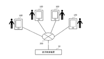
- FIG. 2 is a schematic view showing an example of a usage embodiment of the display control device of the first embodiment.
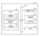
- FIG. 3 is a block diagram showing an example of the hardware configuration of the display control device of the first embodiment.
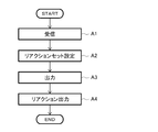
- FIG. 4 is a flowchart showing an example of processing in the display control device of the first embodiment.
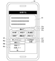
- FIG. 5 is a diagram showing an example of a screen output to the user terminal in the first embodiment.
- FIG. 6 is a block diagram showing a configuration of an example of the display control device according to the second embodiment.
- FIG. 7 is a flowchart showing an example of processing in the display control device of the second embodiment.
- FIG. 1 is a block diagram showing a configuration of an example of the display control device of the first embodiment.
- FIG. 2 is a schematic view showing an example of a usage embodiment of the display control device of the first embodiment.
- FIG. 3 is a block diagram showing an example
- FIG. 8 is a diagram showing an example of a screen output to the user terminal in the third embodiment.
- FIG. 9 is a flowchart showing an example of processing in the display control device of the third embodiment.
- FIG. 10 is a block diagram showing a configuration of an example of the display control device according to the fourth embodiment.
- FIG. 1 is a block diagram showing a configuration of an example of the display control device 10 of the present embodiment.
- the display control device 10 includes a receiving unit 11, a reaction set setting unit 12, and an output unit 13.
- the display control device 10 is also referred to as, for example, a display control system.
- the "post display control device” is also simply referred to as a "display control device”.
- the display control device 10 can be connected to a plurality of user terminals 100 via a communication network 200.
- the terminal 100 is preferably a terminal provided with a display, and specific examples thereof include a mobile phone, a smartphone, a tablet, a PC, and a wearable terminal.
- the communication network 200 is not particularly limited, and a known network can be used.
- the communication network 200 may be wired or wireless.
- Examples of the communication line network 200 include an Internet line, a telephone line, a LAN (Local Area Network), WiFi (Wireless Fidelity), and the like.
- the display control system in the present embodiment may include, for example, a display control device 10 and a user terminal 100.
- the display control device 10 may be, for example, one display control device including the above-mentioned parts, or the display control device 10 may be a display control device in which each part can be connected via the communication network 200.
- the display control device 10 may include, for example, a terminal and a server, and the terminal and the server may be connected to each other via the communication network 200.
- FIG. 3 illustrates a block diagram of the hardware configuration of the display control device 10.
- the display control device 10 includes, for example, a CPU (central processing unit) 101, a memory 102, a bus 103, a communication device 104, a storage device 105, and the like. Each part of the display control device 10 is connected via the bus 103 by, for example, each interface (I / F).
- the CPU 101 is responsible for controlling the entire display control device 10.
- the program of the present invention and other programs are executed by the CPU 101, and various information is read and written.
- the CPU 101 functions as a receiving unit 11, a reaction set setting unit 12, an output unit 13, and a learned model acquisition unit 14, which will be described later.
- a central processing unit such as a GPU may be used instead of the CPU 101.
- Bus 103 can also be connected to, for example, an external device.
- the external device include a terminal, an external storage device (external database, etc.) and the like.
- the display control device 10 can be connected to the communication line network 200 by, for example, the communication device 104 connected to the bus 103, and can also be connected to the external device via the communication line network 200.
- the memory 102 includes, for example, a main memory, and the main memory is also referred to as a main storage device.
- the main memory is, for example, a RAM (random access memory).
- the memory 102 further includes, for example, a ROM (read-only memory).
- the storage device 105 is also referred to as a so-called auxiliary storage device with respect to the main memory (main storage device), for example.
- the storage device 105 stores the operation program 106 including the program of the present invention.
- the storage device 105 includes, for example, a storage medium and a drive for reading and writing to the storage medium.
- the storage medium is not particularly limited, and may be an internal type or an external type, for example, HD (hard disk), FD (floppy (registered trademark) disk), CD-ROM, CD-R, CD-RW, MO, etc. Examples thereof include a DVD, a flash memory, a memory card, and the like, and the drive is not particularly limited.
- the storage device 105 may be, for example, a hard disk drive (HDD) in which a storage medium and a drive are integrated.
- HDD hard disk drive
- the operation program 106 is stored in the storage device 105.
- the storage device 105 may store, for example, information such as the content of the post and the learned model described later.
- the display control device 10 may further include, for example, an input device and an output device such as a display.
- the input device is, for example, a touch panel, a keyboard, a mouse, or the like.
- Examples of the display include an LED display and a liquid crystal display.
- the memory 102 and the storage device 105 can also store access information and log information from the user, as well as information acquired from an external database (not shown).
- the receiving unit 11 receives a post from the user.
- the post is a post in a system such as SNS that enables communication between a plurality of users, and is not particularly limited, and is, for example, a text, an image, or the like.
- the post includes, for example, comments on other posts.
- the reaction set setting unit 12 sets the reaction set to be output in association with the post.
- the reaction set includes a reaction button.
- the reaction button can input a reaction (reaction) to the post.
- the reaction button may be any as long as it is possible to input a reaction to the post, and is not particularly limited. For example, it may be a default one or one created by a user (poster or other user). In addition, characters may or may not be included. Further, it may be text data or image data (icon, stamp, etc.). Specific examples of the reaction button include “Like” and “Congratulations!. In addition, as shown in FIG. 5 to be described later, “same for us”, “don't care”, “helpful”, “mama is hard”, “understand” and the like can be mentioned.
- the number of the reaction buttons included in the reaction set is not particularly limited, and examples thereof include 1 to 10 and 3 to 5.
- the reaction set setting unit 12 may set the reaction set based on the input of the user, for example. Specifically, for example, the user can set in advance the reaction set to be output in association with the post among the plurality of reaction sets.
- the reaction set setting unit 12 may set the reaction set by analyzing the post, for example.
- the analysis is not particularly limited, and examples thereof include context analysis and word analysis.
- the post is tagged (for example, emotional determination) by the analysis.
- the reaction set including the reaction button related to the tag (emotion) can be set.
- the reaction button included in the reaction set may be a default one or a preset one by a user (poster or other user). Further, it may be set for each setting of the reaction set.
- the output unit 13 outputs the post and the reaction button included in the set reaction set in association with each other.
- the output post and the reaction button are transmitted, for example, to the user who is the poster of the post and the terminal of a user other than the poster who can view the post via the communication device 104. It may be displayed on the display or the like of the display control device 10.
- the receiving unit 11 may further receive a reaction to the post in response to an input to the reaction button, for example. Then, the output unit 13 may further output the received reaction, for example.
- the output of the reaction is not particularly limited, and examples thereof include changing the display of numbers on the reaction button as shown in FIG. 5. Specifically, for example, each time the reaction is received, "1" can be added to the number displayed on the reaction button.
- the input to the reaction button is, for example, by a user other than the poster who can view the post.
- the present invention can reduce the stress of the poster by preventing reactions that are inappropriate for the poster. Specifically, for example, it is possible to prevent giving an unintended icon such as "Congratulations" to a poster who posted something unpleasant, and to reduce communication stress due to SNS. can. Also, gaining empathy from others about something, for example, being celebrated by others when something good happens or being comforted by others when something bad happens, reduces the stress of the person. You can get good effects for yourself, such as motivating yourself. According to the present invention, since an appropriate reaction can be set for the poster, it can be expected that such a good effect can be obtained.
- FIG. 4 is a flowchart showing an example of the display control method.
- FIG. 5 is a diagram showing an example of a screen output to the user terminal.
- the display control method of the present embodiment can be implemented as follows, for example, by using the display control device 10 of FIG.
- the display control method of the present embodiment is not limited to the use of the display control device 10 of FIG.
- the receiving unit 11 receives a post from the user (step (A1)). For example, in FIG. 5, posts 20A to 20C are received from the user (“you”) who is using the terminal, which is the display control device 10, and “user A” and “user B”, respectively.
- the reaction set setting unit 12 sets the reaction set to be output in association with the post (step (A2)).
- the reaction set includes a reaction button, which can input a reaction to the post.
- the reaction set 300C is set, and the reaction set 300C includes the reaction buttons 30a to 30f.
- Reaction buttons 30a to 30f can input reactions such as "Like”, “Same for us”, “Understand”, “I don't care”, “Mom is hard”, and "Helpful", respectively.
- the output unit 13 links and outputs the post and the reaction button included in the set reaction set (step (A3)).
- the reaction set 300C is displayed (output) in association with the post 20C.
- the button 3000B is displayed in association with the post 20B, and the reaction set associated with the post 20B is displayed according to the selection of the button 3000B.
- the reaction to the post is received in response to the input to the reaction button, the received reaction is output (step (A4)) and ends (END).
- the reaction of "understand" to the post 20C is displayed according to the selection of the reaction button 30c.
- the reaction set setting unit 12 uses a trained model in which the content of the post is input and the reaction set is output in the setting of the reaction set that is output in association with the post. Set the reaction set. Except for this point, it is the same as that of the first embodiment.
- the trained model may be, for example, one generated by the trained model acquisition unit 14 described later in the display control device 10, or may be separately prepared.
- the content of the post input to the trained model may be, for example, the post itself, or may use the analysis result after analyzing the post.
- the analysis of the post for example, the analysis method of the post described in the first embodiment can be used.
- the display control device 10 may further include a trained model acquisition unit 14, as shown in FIG. 6, for example.
- FIG. 6 is a block diagram showing a configuration of an example of the display control device 10 of the present embodiment.
- the trained model acquisition unit 14 includes a teacher data acquisition unit 141 and a trained model generation unit 142, and the teacher data acquisition unit 141 includes the content of the post and the reaction set output in association with the post.
- the trained model generation unit 142 acquires the teacher data including the above, and uses the acquired teacher data to input the content of the post and generate a trained model that outputs the reaction set.
- the teacher data acquisition unit 141 may acquire the data output from the output unit 13 of the display control device 10 as the teacher data, or may acquire the data prepared separately. Further, the teacher data may be the data of the user, the data of a user other than the user, the data of one person, or the data of a plurality of people.
- the method of generating the trained model by the trained model generation unit 142 is not particularly limited, and a known machine learning method can be used.
- the generation of the trained model by the trained model generation unit 142 may be, for example, a modification of the generated trained model.
- the trained model generation unit 142 calculates the operation parameters of the trained model so that the reaction set output in association with the post is output by the trained model as a candidate for the reaction set. Can be modified.
- FIG. 7 is a flowchart showing an example of the display control method.
- the display control method of the present embodiment can be implemented as follows, for example, by using the display control device 10 of FIG.
- the display control method of the present embodiment is not limited to the use of the display control device 10 of FIG.
- the receiving unit 11 receives a post from the user (step (A1)).
- reaction set setting unit 12 acquires a trained model in which the content of the post is input and the reaction set is output (step (A2'-1)).
- reaction set setting unit 12 sets the reaction set to be output in association with the post using the trained model (step (A2'-2)).
- the output unit 13 links and outputs the post and the reaction button included in the set reaction set (step (A3)).
- the teacher data acquisition unit 141 of the trained model acquisition unit 14 acquires teacher data including the content of the post and the reaction set output in association with the post (step (A4-1)).
- the trained model generation unit 142 of the trained model acquisition unit 14 uses the acquired teacher data to input the content of the post and generate a trained model that outputs the reaction set (step). (A4-2)). Then, the generated trained model is set to be the trained model acquired in the step (A2'-1) (step (A4-3)), and the process ends (END).
- the user's post and the reaction set output in association with the post are acquired as the teacher data, and the trained model is generated. Therefore, by repeatedly executing the steps (A1) to (A4-3), for example, the trained model with higher accuracy can be obtained.
- the reaction set setting unit 12 presents the reaction set candidate to the user in the reaction set setting output in association with the post, and is based on the user's selection of the candidate. , Set the reaction set. Except for this point, it is the same as that of the first embodiment.
- the setting of the reaction set presented as the candidate can be performed in the same manner as the setting of the reaction set in the embodiment, for example.
- a label corresponding to the reaction set candidate may be set and the label may be displayed.
- the label may or may not be related, for example, to the content of the candidate reaction set (eg, number, etc.).
- the label may be a classification of the user's emotions, a classification by a topic in a post, or the like. Examples of the classification of the user's emotions include “praise", “comfort”, and “sympathize”.
- the reaction set candidate with the label "praise” includes the reaction buttons such as "Like” and "Congratulations!. Examples of the topics classified by the topic in the above-mentioned post include “animals” and the like.
- the reaction set candidate with the label "dog" includes the reaction button with a dog icon.
- the topic in the post may be set in advance, or may be set by analyzing the post or the like.
- the topic in the post may be the main topic of a series of posts or the topic of an individual post.
- the label may be, for example, a default label or may be arbitrarily set by the user.
- the presentation of the reaction set candidates is not limited to the display of the label, and for example, the reaction buttons included in the reaction set candidates may be displayed in a list.
- the presentation of the reaction set candidate can be, for example, the same as the output by the output unit 13.
- the label may be displayed, for example, by displaying a button (also referred to as a candidate button) corresponding to the candidate in the reaction set.
- FIG. 8 shows an example of the candidate button.
- candidate buttons 40a to 40c are displayed in association with the post 20.
- the reaction set can be set based on the selection of the candidate buttons 40a to 40c by the user.
- the candidate for the reaction set may include, for example, a plurality of the reaction sets as candidates, or may include one reaction set as a candidate.
- the reaction set setting unit 12 may further accept an evaluation by the user for the reaction set presented to the user as the candidate. Then, the setting of the reaction set presented as the candidate may be modified according to the evaluation. Thereby, for example, the reaction set that is not preferable for the user can be prevented from being output as a candidate for the reaction set.
- FIG. 9 is a flowchart showing an example of the display control method.
- the receiving unit 11 receives a post from the user (step (A1)).
- the post 20 is received (acceptance of input / editing) from the user who is using the terminal which is the display control device 10.
- the reaction set setting unit 12 presents the reaction set candidate to the user (step (A2 ′′ -1)).
- the candidate button 40 is presented as a candidate for the reaction set.
- the candidate button 40 is displayed as " ⁇ reaction”, and when the user selects the candidate button 40, the candidate buttons 40a to 40c corresponding to the candidate of the reaction set are displayed by the pull-down display.
- the candidate buttons 40a to 40c correspond to the candidates of the reaction set of "praise!, "Comfort!, And "sympathize!, Respectively.
- the reaction set setting unit 12 sets the reaction set based on the selection of the candidate by the user (step (A2 ′′ -2)).
- the reaction buttons 31a to 31f included in the reaction set of "praise! Are preview-displayed based on the selection of the candidate button 40a by the user.
- the reaction buttons 31a to 31f can be set in association with the post 20.
- the output unit 13 links and outputs the post and the reaction button included in the set reaction set (step (A3)), and then ends (END).
- the post 20 and the reaction buttons 31a to 31f are output in association with the screen (not shown) of the terminal of the user who posted or another user.
- the trained model acquisition unit 14 includes a teacher data acquisition unit 341 and a trained model generation unit 342. Except for this point, it is the same as that of the second embodiment. That is, also in the present embodiment, the reaction set setting unit 12 sets the trained model in which the content of the post is input and the reaction set is output in the setting of the reaction set that is output in association with the post. Use to set the reaction set.
- the reaction set output by the trained model may be a candidate for the reaction set.
- the teacher data acquisition unit 341 acquires teacher data including the content of the post and the reaction set presented to the user as the candidate. Then, the reaction set presented to the user as the candidate is associated with information regarding whether or not it is output in association with the post.
- the trained model generation unit 342 inputs the content of the post using the acquired teacher data, and outputs the reaction set presented to the user as the candidate in association with the post. Generate a trained model that outputs the reaction set.
- the trained model generation unit 342 for example, among the reaction sets presented to the user as the candidates for the trained model that has been generated, the reaction set output in association with the post is described. As a candidate for the reaction set, the arithmetic parameters of the trained model may be modified so as to be output by the trained model.
- the reaction sets that are not output in association with the post are trained as candidates for the reaction sets.
- the arithmetic parameters of the trained model may be modified so that they are not output by the model.
- the reaction set output in association with the post is output by the trained model.
- the appropriate reaction set can be output.
- the present embodiment relates to a trained model and a method of generating the trained model.
- the trained model (also referred to as a discriminator) of the present embodiment includes an input layer, an output layer, and an intermediate layer, the input layer is input with the content of a post from a user, and the output layer is the post.
- the reaction set that is output in association with the post is output, the intermediate layer inputs the content of the post from the user, and the parameter is set using the teacher data that outputs the reaction set that is output in association with the post.
- the computer has been trained so that the content of the post from the user is input to the input layer, the operation is performed in the intermediate layer, and the reaction set output in association with the post is output from the output layer. To work.
- the trained model can be generated, for example, based on a known machine learning method. Further, for example, it may be generated by the method of generating a trained model described later.
- the trained model generation method of the present embodiment includes a teacher data acquisition step and a trained model generation step, and the teacher data acquisition step includes the content of the post and the reaction output in association with the post.
- the teacher data including the set is acquired, and the trained model generation step uses the acquired teacher data to input the content of the post and generate a trained model that outputs the reaction set.
- the method of generating the trained model of the present embodiment includes a teacher data acquisition step and a trained model generation step, and the teacher data acquisition step is presented to the user as the content of the post and the candidate.
- the teacher data including the reaction set is acquired, and the reaction set presented to the user as the candidate is associated with information regarding whether or not it is output in association with the post, and has been learned.
- the learned model may be generated by inputting the content of the post and outputting the reaction set by using the acquired teacher data.
- the program of the present embodiment is a program for causing a computer to execute each step of the method of the present invention as a procedure.
- "procedure” may be read as "processing”.
- the program of the present embodiment may be recorded on a computer-readable recording medium, for example.
- the recording medium is not particularly limited, and examples thereof include a read-only memory (ROM), a hard disk (HD), an optical disk, a floppy (registered trademark) disk (FD), and the like.
- (Appendix 1) It has a receiving unit, a reaction set setting unit, and an output unit.
- the receiver receives a post from the user and
- the reaction set setting unit sets a reaction set to be output in association with the post, and sets the reaction set.
- the reaction set includes a reaction button.
- the reaction button can input a reaction to the post,
- the output unit outputs the post and the reaction button included in the set reaction set in association with each other.
- (Appendix 2) The display control device according to Appendix 1, wherein the reaction set setting unit presents a candidate for the reaction set to the user and sets the reaction set based on the selection of the candidate by the user.
- the reaction set setting unit presents the user with a button corresponding to the candidate of the reaction set.
- the display control device according to Appendix 2 wherein the reaction set setting unit sets the reaction set based on the selection of the button by the user.
- the display control device according to any one of Appendix 1 to 3 wherein the reaction set setting unit sets the reaction set by analyzing the post.
- the display control device according to Appendix 4 wherein the reaction set setting unit sets the reaction set by analyzing the context of the post.
- the trained model acquisition unit includes a teacher data acquisition unit and a trained model generation unit.
- the teacher data acquisition unit acquires teacher data including the content of the post and the reaction set output in association with the post.
- the display control device according to Appendix 6, wherein the trained model generation unit generates the trained model by inputting the content of the post and outputting the reaction set by using the acquired teacher data.
- the teacher data acquisition unit acquires the teacher data including the content of the post and the reaction set presented to the user as the candidate.
- the reaction set presented to the user as the candidate is associated with information regarding whether or not it was output in association with the post.
- the trained model generation unit inputs the content of the post using the acquired teacher data, and outputs the reaction set presented to the user as the candidate in association with the post.
- the display control device according to Appendix 7, which generates a trained model that outputs a reaction set.
- Appendix 9 In the trained model generation unit, among the reaction sets presented to the user as the candidates, the reaction set that is not output in association with the post is used as the candidate for the reaction set by the trained model.
- the display control device according to Appendix 8 which modifies the arithmetic parameters of the trained model so as not to be output. (Appendix 10) It has a receiving process, a reaction set setting process, and an output process.
- the receiving process receives a post from the user and In the reaction set setting process, a reaction set to be output in association with the post is set, and the reaction set is set.
- the reaction set includes a reaction button.
- the reaction button can input a reaction to the post, In the output process, the post and the reaction button included in the set reaction set are linked and output.
- Post display control method (Appendix 11) The display control method according to Appendix 10, wherein the reaction set setting step presents a candidate for the reaction set to the user and sets the reaction set based on the selection of the candidate by the user. (Appendix 12) In the reaction set setting step, the user is presented with a candidate button corresponding to the candidate of the reaction set.
- Appendix 13 The display control method according to any one of Appendix 10 to 12, wherein the reaction set setting step sets the reaction set by analyzing the post.
- Appendix 14 The display control method according to Appendix 13, wherein the reaction set setting step sets the reaction set by analyzing the context of the post.
- Appendix 15 The display control method according to any one of Supplementary note 10 to 14, wherein the reaction set setting step sets the reaction set using a trained model in which the content of the post is input and the reaction set is output.
- Appendix 16 In addition, it includes a trained model acquisition process.
- the trained model acquisition step includes a teacher data acquisition step and a trained model generation step.
- the teacher data acquisition step acquires teacher data including the content of the post and the reaction set output in association with the post.
- the teacher data acquisition step acquires the teacher data including the content of the post and the reaction set presented to the user as the candidate.
- the reaction set presented to the user as the candidate is associated with information regarding whether or not it was output in association with the post.
- the content of the post is input using the acquired teacher data, and the reaction set presented to the user as the candidate is output in association with the post.
- the display control method according to Appendix 16 which generates a trained model that outputs a reaction set.
- Appendix 18 In the trained model generation step, among the reaction sets presented to the user as the candidates, the reaction set that is not output in association with the post is used as the candidate for the reaction set by the trained model.
- Appendix 19 A program that allows the computer to perform receive, reaction set, and output procedures: The receiving procedure receives a post from a user and The reaction set setting procedure sets the reaction set to be output in association with the post, and then sets the reaction set.
- the reaction set includes a reaction button.
- the reaction button can input a reaction to the post, In the output procedure, the post and the reaction button included in the set reaction set are linked and output.
- Appendix 20 The program according to Appendix 19, wherein the reaction set setting procedure presents a candidate for the reaction set to the user and sets the reaction set based on the selection of the candidate by the user.
- Appendix 21 The reaction set setting procedure presents the user with a candidate button corresponding to the candidate of the reaction set.
- the program according to Appendix 20 wherein the reaction set setting procedure sets the reaction set based on the selection of the candidate button by the user.
- Appendix 22 The program according to any one of Appendix 19 to 21, wherein the reaction set setting procedure sets the reaction set by analyzing the post.
- (Appendix 23) The program according to Appendix 22, wherein the reaction set setting procedure sets the reaction set by analyzing the context of the post.
- (Appendix 24) The program according to any one of Appendix 19 to 23, wherein the reaction set setting procedure sets the reaction set using a trained model in which the content of the post is input and the reaction set is output.
- (Appendix 25) In addition, it includes a trained model acquisition procedure.
- the trained model acquisition procedure includes a teacher data acquisition procedure and a trained model generation procedure.
- the teacher data acquisition procedure acquires teacher data including the content of the post and the reaction set output in association with the post.
- the program according to Appendix 24, wherein the trained model generation procedure uses the acquired teacher data to input the content of the post and generate the trained model with the reaction set as an output.
- the teacher data acquisition procedure acquires the teacher data including the content of the post and the reaction set presented to the user as the candidate.
- the reaction set presented to the user as the candidate is associated with information regarding whether or not it was output in association with the post.
- the content of the post is input using the acquired teacher data, and the reaction set presented to the user as the candidate is output in association with the post.
- the program according to Appendix 25, which generates a trained model that outputs a reaction set.
- Appendix 27 In the trained model generation procedure, among the reaction sets presented to the user as the candidates, the reaction set that is not output in association with the post is used as the candidate for the reaction set by the trained model.
- Appendix 28 A computer-readable recording medium on which the program according to any one of Appendix 19 to 27 is recorded.
- the present invention it is possible to provide a system capable of reducing the stress of the poster by preventing reactions that are inappropriate for the poster. In addition, troubles between users can be prevented.
Landscapes
- Engineering & Computer Science (AREA)
- Theoretical Computer Science (AREA)
- Business, Economics & Management (AREA)
- Tourism & Hospitality (AREA)
- Physics & Mathematics (AREA)
- General Physics & Mathematics (AREA)
- Economics (AREA)
- Health & Medical Sciences (AREA)
- General Engineering & Computer Science (AREA)
- General Health & Medical Sciences (AREA)
- Human Resources & Organizations (AREA)
- Marketing (AREA)
- Primary Health Care (AREA)
- Strategic Management (AREA)
- General Business, Economics & Management (AREA)
- Management, Administration, Business Operations System, And Electronic Commerce (AREA)
- User Interface Of Digital Computer (AREA)
Priority Applications (1)
| Application Number | Priority Date | Filing Date | Title |
|---|---|---|---|
| JP2022511630A JP7376185B2 (ja) | 2020-04-02 | 2021-02-15 | 投稿の表示制御装置、投稿の表示制御方法、およびプログラム |
Applications Claiming Priority (2)
| Application Number | Priority Date | Filing Date | Title |
|---|---|---|---|
| JP2020066945 | 2020-04-02 | ||
| JP2020-066945 | 2020-04-02 |
Publications (1)
| Publication Number | Publication Date |
|---|---|
| WO2021199727A1 true WO2021199727A1 (ja) | 2021-10-07 |
Family
ID=77928293
Family Applications (1)
| Application Number | Title | Priority Date | Filing Date |
|---|---|---|---|
| PCT/JP2021/005437 Ceased WO2021199727A1 (ja) | 2020-04-02 | 2021-02-15 | 投稿の表示制御装置、投稿の表示制御方法、およびプログラム |
Country Status (2)
| Country | Link |
|---|---|
| JP (1) | JP7376185B2 (https=) |
| WO (1) | WO2021199727A1 (https=) |
Cited By (1)
| Publication number | Priority date | Publication date | Assignee | Title |
|---|---|---|---|---|
| JP2025026793A (ja) * | 2023-08-11 | 2025-02-25 | 株式会社カカオ | コンテンツに対するリアクションセットを提供する方法、端末及びサーバー |
Citations (2)
| Publication number | Priority date | Publication date | Assignee | Title |
|---|---|---|---|---|
| JP2013254420A (ja) * | 2012-06-08 | 2013-12-19 | Nippon Telegr & Teleph Corp <Ntt> | 質問応答装置、モデル学習装置、方法、及びプログラム |
| WO2016203805A1 (ja) * | 2015-06-15 | 2016-12-22 | ソニー株式会社 | 情報処理装置、情報処理システム、情報処理方法及びプログラム |
-
2021
- 2021-02-15 JP JP2022511630A patent/JP7376185B2/ja active Active
- 2021-02-15 WO PCT/JP2021/005437 patent/WO2021199727A1/ja not_active Ceased
Patent Citations (2)
| Publication number | Priority date | Publication date | Assignee | Title |
|---|---|---|---|---|
| JP2013254420A (ja) * | 2012-06-08 | 2013-12-19 | Nippon Telegr & Teleph Corp <Ntt> | 質問応答装置、モデル学習装置、方法、及びプログラム |
| WO2016203805A1 (ja) * | 2015-06-15 | 2016-12-22 | ソニー株式会社 | 情報処理装置、情報処理システム、情報処理方法及びプログラム |
Cited By (2)
| Publication number | Priority date | Publication date | Assignee | Title |
|---|---|---|---|---|
| JP2025026793A (ja) * | 2023-08-11 | 2025-02-25 | 株式会社カカオ | コンテンツに対するリアクションセットを提供する方法、端末及びサーバー |
| JP7785863B2 (ja) | 2023-08-11 | 2025-12-15 | 株式会社カカオ | コンテンツに対するリアクションセットを提供する方法、端末及びサーバー |
Also Published As
| Publication number | Publication date |
|---|---|
| JPWO2021199727A1 (https=) | 2021-10-07 |
| JP7376185B2 (ja) | 2023-11-08 |
Similar Documents
| Publication | Publication Date | Title |
|---|---|---|
| US11328116B2 (en) | Intelligently identifying collaborators for a document | |
| US10839149B2 (en) | Generating templates from user's past documents | |
| US20200142545A1 (en) | Document contribution management system | |
| JP2017215996A (ja) | 変更要求フォームの注釈 | |
| US10891441B2 (en) | Apparatus, system, and method of assisting information sharing, and recording medium | |
| JP6637947B2 (ja) | 認知ロボット工学アナライザ | |
| US11522924B2 (en) | Notifications regarding updates to collaborative content | |
| Smith et al. | A scoping review to identify the techniques frequently used when analysing qualitative visual data | |
| Johnson et al. | Engagement-oriented design: a study of New Zealand public cultural heritage institutions crowdsourcing platforms | |
| JP2024035205A (ja) | 意見分析システム、意見分析方法、及びプログラム | |
| JP5893825B2 (ja) | ワークフローのための方法及びシステム | |
| Heijkant et al. | Framing pension reform in the news: Traditional versus social media | |
| Ouyang | Assessing meaning-dimension quality in consecutive interpreting training | |
| KR20180039019A (ko) | 상황-특정 기록 프레임워크와 관련된 방법 및 시스템 | |
| Ndindeng | The impact of social media on mental health | |
| Gan | Different registers, different grammars in second language production? The dative alternation in spoken and written Chinese learner English | |
| WO2021199727A1 (ja) | 投稿の表示制御装置、投稿の表示制御方法、およびプログラム | |
| JP2021012646A (ja) | 情報処理装置、情報処理方法および情報処理プログラム | |
| Pedroso Carvalho et al. | SIM-SR—Semiotic Inspection Method Mediated by Screen Reader: Analysing the Benefits of Bringing Communicability to the Accessibility Evaluation Table | |
| Kwon | Aspect-based sentiment analysis through zero-shot text classification and impact-asymmetry analysis | |
| JP2023014159A (ja) | 分類システム、及び、分類方法 | |
| JP5246309B2 (ja) | 情報処理装置及び情報処理プログラム | |
| KR20230051963A (ko) | 외국 입시 컨설팅 서비스 제공 시스템 | |
| US20250371265A1 (en) | System and method for annotation-guided document summarization through generative artificial intelligence | |
| JP7727351B1 (ja) | 情報共有装置、情報共有方法、及び情報共有プログラム |
Legal Events
| Date | Code | Title | Description |
|---|---|---|---|
| 121 | Ep: the epo has been informed by wipo that ep was designated in this application |
Ref document number: 21780433 Country of ref document: EP Kind code of ref document: A1 |
|
| ENP | Entry into the national phase |
Ref document number: 2022511630 Country of ref document: JP Kind code of ref document: A |
|
| NENP | Non-entry into the national phase |
Ref country code: DE |
|
| 122 | Ep: pct application non-entry in european phase |
Ref document number: 21780433 Country of ref document: EP Kind code of ref document: A1 |