WO2021199530A1 - Caliper body mounting structure for vehicle disc brake - Google Patents
Caliper body mounting structure for vehicle disc brake Download PDFInfo
- Publication number
- WO2021199530A1 WO2021199530A1 PCT/JP2020/047728 JP2020047728W WO2021199530A1 WO 2021199530 A1 WO2021199530 A1 WO 2021199530A1 JP 2020047728 W JP2020047728 W JP 2020047728W WO 2021199530 A1 WO2021199530 A1 WO 2021199530A1
- Authority
- WO
- WIPO (PCT)
- Prior art keywords
- caliper
- mounting
- bracket
- disc
- vehicle
- Prior art date
Links
Images


Classifications
-
- F—MECHANICAL ENGINEERING; LIGHTING; HEATING; WEAPONS; BLASTING
- F16—ENGINEERING ELEMENTS AND UNITS; GENERAL MEASURES FOR PRODUCING AND MAINTAINING EFFECTIVE FUNCTIONING OF MACHINES OR INSTALLATIONS; THERMAL INSULATION IN GENERAL
- F16D—COUPLINGS FOR TRANSMITTING ROTATION; CLUTCHES; BRAKES
- F16D55/00—Brakes with substantially-radial braking surfaces pressed together in axial direction, e.g. disc brakes
- F16D55/02—Brakes with substantially-radial braking surfaces pressed together in axial direction, e.g. disc brakes with axially-movable discs or pads pressed against axially-located rotating members
- F16D55/22—Brakes with substantially-radial braking surfaces pressed together in axial direction, e.g. disc brakes with axially-movable discs or pads pressed against axially-located rotating members by clamping an axially-located rotating disc between movable braking members, e.g. movable brake discs or brake pads
- F16D55/228—Brakes with substantially-radial braking surfaces pressed together in axial direction, e.g. disc brakes with axially-movable discs or pads pressed against axially-located rotating members by clamping an axially-located rotating disc between movable braking members, e.g. movable brake discs or brake pads with a separate actuating member for each side
-
- F—MECHANICAL ENGINEERING; LIGHTING; HEATING; WEAPONS; BLASTING
- F16—ENGINEERING ELEMENTS AND UNITS; GENERAL MEASURES FOR PRODUCING AND MAINTAINING EFFECTIVE FUNCTIONING OF MACHINES OR INSTALLATIONS; THERMAL INSULATION IN GENERAL
- F16D—COUPLINGS FOR TRANSMITTING ROTATION; CLUTCHES; BRAKES
- F16D65/00—Parts or details
- F16D65/02—Braking members; Mounting thereof
Definitions
- the present invention relates to a caliper body mounting structure for a vehicle disc brake, and more particularly to a vehicle disc brake caliper body mounting structure for mounting a radial mount type vehicle disc brake to a vehicle body via a bracket.
- bolt insertion holes in the direction orthogonal to the disk axis are formed on both sides of the disk circumferential direction in the working portion provided with the piston of the caliper body, and the caliper mounting bolts inserted through the bolt insertion holes are fastened to the vehicle body side.
- Some of the radial mount type caliper bodies that can be attached are attached by fastening the male screw portion of the caliper mounting bolt inserted into the bolt insertion hole to the caliper mounting portion that is integrally projected from the wheel suspension device (for example, Patent Document). See 1.).
- a bolt insertion hole in the disc axial direction is formed on the disc feeding side and the disc inner peripheral side in the working portion of the caliper body provided with the piston, and the caliper mounting bolt inserted through the bolt insertion hole is fastened to the vehicle body side.
- Some of the axial mount type caliper bodies that are mounted in this way are mounted by fastening the male screw portion of the caliper mounting bolt inserted into the bolt insertion hole to the caliper mounting portion that is integrally projected from the wheel suspension device (for example,). See Patent Document 2).
- the radial mount type caliper body of Patent Document 1 described above has an advantage that the mounting rigidity is high, but the caliper body does not behave even if it receives a rotational moment generated in the disc rotation direction during braking. It was necessary to secure a sufficient coupling area between the caliper mounting portion and the caliper mounting portion, and the caliper mounting portion was enlarged. Further, the radial mount type caliper body could not be directly attached to the caliper attachment portion of the wheel suspension device.
- an object of the present invention is to provide a caliper body mounting structure for a vehicle disc brake that can be mounted on a wide range of wheel suspension devices while ensuring mounting rigidity of a radial mount type caliper body.
- the caliper body mounting structure of the vehicle disc brake of the present invention has a bolt in a direction orthogonal to the disc axis at an action portion provided with a piston of the caliper body arranged so as to straddle the outer periphery of the disc rotor.
- a caliper body mounting structure for vehicle disc brakes in which insertion holes are formed on both sides in the circumferential direction of the disc and the caliper body is attached to the caliper mounting portion provided in the wheel suspension device by using caliper mounting bolts that are inserted into the bolt insertion holes.
- a caliper bracket having a caliper mounting hole in a direction orthogonal to the disc axis to which the caliper body is mounted and a vehicle body mounting hole in the disc axis direction to be mounted on the caliper mounting portion is formed, and a disc is formed in the caliper mounting portion.
- An axial bracket mounting hole is formed, a vehicle body mounting bolt is fastened over the vehicle body mounting hole and the bracket mounting hole, and the caliper mounting bolt is fastened over the bolt insertion hole and the caliper mounting hole.
- the caliper bracket is arranged on the outside of the vehicle body of the caliper mounting portion, and is a female screw screwed into the male screw portion of the vehicle body mounting bolt at a position corresponding to the bracket mounting hole on the inside of the vehicle body of the caliper mounting portion.
- the caliper bracket is attached to the caliper bracket by arranging a plate-shaped fastening member provided with a portion and fastening the male screw portion of the vehicle body mounting bolt inserted through the vehicle body mounting hole and the bracket mounting hole to the female screw portion. It is preferable to attach it to the caliper mounting part.
- bracket mounting holes are formed, and the fastening member is integrally formed with female screw portions arranged at positions corresponding to the plurality of bracket mounting holes via the connecting portion.
- the caliper mounting portion can be miniaturized while ensuring the mounting rigidity of the radial mount type caliper body. Furthermore, it is possible to attach the radial mount type caliper body to the caliper mounting part of the wheel suspension device that attaches the axial mount type caliper body, and the radial mount type caliper body can be attached to the caliper mounting part of the axial mount type wheel suspension device. It can be attached to a wider range of wheel suspension devices, including parts. Furthermore, by changing the shape of the caliper bracket, the mounting position of the caliper body can be adjusted according to the size of the outer diameter of the disc rotor and the dimension of the wheel suspension device, improving the layout. be able to.
- the caliper bracket is arranged on the outside of the vehicle body of the caliper mounting portion, and is provided with a female screw portion screwed into the male screw portion of the vehicle body mounting bolt at a position corresponding to the bracket mounting hole on the inside of the vehicle body of the caliper mounting portion.
- the mounting rigidity of the caliper bracket can be increased, even if the caliper body receives a rotational moment generated in the disc rotation direction during braking, the rotational moment can be reliably received by the caliper body and the caliper bracket. It is possible to suppress the behavior of the body.
- a plurality of bracket mounting holes are formed, and the fastening member is integrally formed with female screw portions arranged at positions corresponding to the plurality of bracket mounting holes via the connecting portion, whereby the caliper bracket assembly work is performed.
- the caliper bracket can be assembled to the caliper mounting portion with high accuracy.
- FIG. 1 is a sectional view taken along line IV-IV of FIG. It is a front view which shows one form example of the caliper body mounting structure of this invention.
- FIG. 1 to 5 are views showing an example of a caliper body mounting structure of the vehicle disc brake of the present invention.
- the arrow A indicates the rotation direction of the disc rotor that rotates integrally with the wheel when the vehicle is moving forward, and the disc feeding side and the disc turning side described below are assumed to be when the vehicle is moving forward.
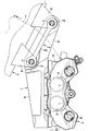
- a radial mount type caliper body 2 is attached to a pair of caliper mounting portions 3a and 3a provided on the lower end side of a front fork 3 (wheel suspension device) via a caliper bracket 4. Is installed.
- the caliper body 2 has a pair of action portions 2a and 2a supported on the lower end of the front fork 3 and arranged to face each other on both side portions of the disc rotor 5 which rotates integrally with the wheels, and these are straddled over the outer periphery of the disc rotor 5. Cylinder holes 2c and 2c are formed in the working portions 2a and 2a, respectively, which are provided with a bridge portion 2b for connecting and accommodate the pistons 7 and 7 for pressing the friction pad 6 on the disc rotor 5.
- mounting boss portions 2d and 2d are formed in the action portion 2a on the vehicle body mounting side arranged on one side portion of the disc rotor 5, and bolt insertion holes formed in the mounting boss portions 2d and 2d. It is attached to the caliper bracket 4 by using the caliper mounting bolts 8 and 8 that are inserted into the 2e and 2e.
- the mounting boss portions 2d and 2d are the disc shafts connecting the disc rotor 5 rotation center and the caliper body 2 pad pressing center in the direction orthogonal to the disc shaft on the disc insertion side and the disc exit side of the action portion 2a.
- the bolt insertion holes 2e and 2e having a diameter slightly larger than that of the caliper mounting bolts 8 and 8 are formed in the mounting boss portions 2d and 2d by overlaying them in the direction parallel to the virtual line L1 in the orthogonal direction to the disc. It is formed through in a direction parallel to the above-mentioned virtual line L1 orthogonal to the axis.
- the caliper mounting portions 3a and 3a formed on the front fork 3 are projected from the outside of the front fork 3 in the radial direction of the disc and the inside of the radial direction of the disc on the rear side of the vehicle body, and the caliper bracket 4 uses the vehicle body mounting bolt 9. It is attached via a plate-shaped fastening member 10. Bracket mounting holes 3b and 3b having a diameter slightly larger than that of the vehicle body mounting bolts 9 and 9 are formed through the caliper mounting portions 3a and 3a in the disk axial direction.
- the caliper bracket 4 is provided from the vehicle body mounting arm 4a attached to the caliper mounting portions 3a and 3a and the inner end of the vehicle body mounting arm 4a in the radial direction of the disk in a direction substantially orthogonal to the virtual line L1 orthogonal to the disk axis. It is equipped with a caliper body mounting arm 4b that extends.
- the caliper body mounting arm 4b is coaxial with the bolt insertion holes 2e and 2e, and is internally provided with female screw holes 4c and 4c (caliper mounting holes) screwed into the male screw portions 8a and 8a of the caliper mounting bolts 8 and 8. It is provided with boss portions 4d and 4d.
- the vehicle body mounting arm 4a is coaxial with the bracket mounting holes 3b and 3b, and the vehicle body mounting holes 4e and 4e having a diameter slightly larger than that of the vehicle body mounting bolts 9 and 9 are formed through.
- the fastening member 10 is formed in a plate shape in which female threaded portions 10a and 10a arranged at positions corresponding to the bracket mounting holes 3b and 3b and a connecting portion 10b connecting the female threaded portions 10a and 10a are integrally provided.
- the female threaded portions 10a and 10a are formed so as to be screwed into the male threaded portions 9a and 9a of the vehicle body mounting bolts 9 and 9.
- the body mounting arm 4a of the caliper bracket 4 is arranged on the outside of the vehicle body of the caliper mounting portions 3a and 3a of the front fork 3, and the bracket mounting holes on the inside of the vehicle body of the caliper mounting portions 3a and 3a are arranged.
- the female threaded portions 10a and 10a of the fastening member 10 are arranged at positions corresponding to 3b and 3b, and the male threaded portions of the vehicle body mounting bolts 9 and 9 inserted through the vehicle body mounting holes 4e and 4e and the bracket mounting holes 3b and 3b.
- the outer peripheral side surfaces of the discs of the boss portions 4d and 4d of the caliper body mounting arm 4b of the caliper bracket 4 and the inner peripheral side surfaces of the discs of the mounting boss portions 2d and 2d of the caliper body 2 are aligned with each other in the bolt insertion holes 2e and 2e.
- the caliper body 2 is attached to the caliper bracket 4 by inserting the caliper mounting bolts 8 and 8 and fastening the male screw portions 8a and 8a to the female screw holes 4c and 4c.
- the caliper mounting portions 3a and 3a can be made smaller than before while ensuring the mounting rigidity of the radial mount type caliper body 2.
- the radial mount type caliper body 2 can be attached to the caliper mounting portion of the wheel suspension device for attaching the axial mount type caliper body 2, and the radial mount type caliper body can be attached to the axial mount type wheel suspension device. It can be mounted on a wider range of wheel suspension devices, including the caliper mount.
- the shape of the caliper bracket 4 the mounting position of the caliper body 2 can be adjusted according to the size of the outer peripheral diameter of the disc rotor 5 and the dimension of the wheel suspension device, and the layout can be improved. It can be improved.
- the caliper bracket 4 is arranged on the outside of the vehicle body of the caliper mounting portions 3a and 3a, and the fastening member 10 is arranged on the inside of the vehicle body of the caliper mounting portions 3a and 3a.
- the mounting rigidity of the caliper bracket can be increased, even if the caliper body 2 receives a rotational moment generated in the disc rotation direction during braking, the rotational moment can be reliably received by the caliper body and the caliper bracket. It is possible to suppress the behavior of the caliper body 2.
- the fastening member 10 is integrally formed with two female threaded portions 10a and 10a arranged at positions corresponding to the bracket mounting holes 3b and 3b and a connecting portion 10b connecting these female threaded portions 10a and 10a.
- the caliper bracket 4 can be easily assembled, and the caliper bracket 4 can be accurately assembled to the caliper mounting portions 3a and 3a.
- the present invention is not limited to the above-mentioned embodiment, and the number of cylinder holes formed in the caliper body is arbitrary. Further, the shapes of the body mounting arm and the caliper body mounting arm of the caliper bracket may be formed in any shape according to the size and shape of the caliper body. Further, the fastening member may not have the female threaded portion connected by the connecting portion.
Abstract
Provided is a caliper body mounting structure for a vehicle disc brake, which can be mounted on a wide range of wheel suspension devices while ensuring the mounting rigidity of a radial mount caliper body. In the working portion of a caliper body 2, bolt insertion holes 2e, 2e in a direction orthogonal to a disc axis are formed on both sides in the circumferential direction of the disc. A caliper bracket 4 is formed with: internally threaded holes 4c, 4c (caliper mounting holes) in the direction orthogonal to the disc axis, for mounting the caliper body 2; and vehicle body mounting holes 4e, 4e in the disc axis direction, for mounting the caliper body 2 to caliper mounting portions 3a, 3a that are formed on a front fork 3. The caliper body 2 is mounted to the caliper mounting portions 3a, 3a with the caliper bracket 4 interposed therebetween.
Description
本発明は、車両用ディスクブレーキのキャリパボディ取付け構造に関し、詳しくは、ラジアルマウントタイプの車両用ディスクブレーキをブラケットを介して車体に取り付ける車両用ディスクブレーキのキャリパボディ取付け構造に関する。
The present invention relates to a caliper body mounting structure for a vehicle disc brake, and more particularly to a vehicle disc brake caliper body mounting structure for mounting a radial mount type vehicle disc brake to a vehicle body via a bracket.
従来、キャリパボディのピストンを備えた作用部に、ディスク軸と直交する方向のボルト挿通孔をディスク周方向両側部に形成し、該ボルト挿通孔に挿通したキャリパ取付ボルトを車体側に締結して取り付けられるラジアルマウントタイプのキャリパボディでは、車輪懸架装置に一体に突設したキャリパ取付部に、ボルト挿通孔に挿通したキャリパ取付ボルトの雄ねじ部を締結して取り付けるものがあった(例えば、特許文献1参照。)。また、キャリパボディのピストンを備えた作用部に、ディスク軸方向のボルト挿通孔をディスク回出側とディスク内周側とに形成し、該ボルト挿通孔に挿通したキャリパ取付ボルトを車体側に締結して取り付けられるアキシャルマウントタイプのキャリパボディでも、車輪懸架装置に一体に突設したキャリパ取付部に、ボルト挿通孔に挿通したキャリパ取付ボルトの雄ねじ部を締結して取り付けるものがあった(例えば、特許文献2参照。)。
Conventionally, bolt insertion holes in the direction orthogonal to the disk axis are formed on both sides of the disk circumferential direction in the working portion provided with the piston of the caliper body, and the caliper mounting bolts inserted through the bolt insertion holes are fastened to the vehicle body side. Some of the radial mount type caliper bodies that can be attached are attached by fastening the male screw portion of the caliper mounting bolt inserted into the bolt insertion hole to the caliper mounting portion that is integrally projected from the wheel suspension device (for example, Patent Document). See 1.). Further, a bolt insertion hole in the disc axial direction is formed on the disc feeding side and the disc inner peripheral side in the working portion of the caliper body provided with the piston, and the caliper mounting bolt inserted through the bolt insertion hole is fastened to the vehicle body side. Some of the axial mount type caliper bodies that are mounted in this way are mounted by fastening the male screw portion of the caliper mounting bolt inserted into the bolt insertion hole to the caliper mounting portion that is integrally projected from the wheel suspension device (for example,). See Patent Document 2).
しかし、上述の特許文献1のラジアルマウントタイプのキャリパボディは、取付剛性が高くなる利点はあるが、制動時にディスク回転方向に発生する回転モーメントを受けてもキャリパボディが挙動しないように、キャリパボディとキャリパ取付部との結合面積を充分に確保する必要があり、キャリパ取付部が大型化していた。さらに、ラジアルマウントタイプのキャリパボディを、車輪懸架装置のキャリパ取付部にそのまま取り付けることはできなかった。
However, the radial mount type caliper body of Patent Document 1 described above has an advantage that the mounting rigidity is high, but the caliper body does not behave even if it receives a rotational moment generated in the disc rotation direction during braking. It was necessary to secure a sufficient coupling area between the caliper mounting portion and the caliper mounting portion, and the caliper mounting portion was enlarged. Further, the radial mount type caliper body could not be directly attached to the caliper attachment portion of the wheel suspension device.
そこで本発明は、ラジアルマウントタイプのキャリパボディの取付剛性を確保しながら、広範囲の車輪懸架装置に取り付けることができる車両用ディスクブレーキのキャリパボディ取付け構造を提供することを目的としている。
Therefore, an object of the present invention is to provide a caliper body mounting structure for a vehicle disc brake that can be mounted on a wide range of wheel suspension devices while ensuring mounting rigidity of a radial mount type caliper body.
上記目的を達成するため、本発明の車両用ディスクブレーキのキャリパボディ取付け構造は、ディスクロータの外周を跨いで配置されるキャリパボディのピストンを備えた作用部に、ディスク軸と直交する方向のボルト挿通孔をディスク周方向両側部に形成し、前記ボルト挿通孔に挿通するキャリパ取付ボルトを用いて、車輪懸架装置に設けたキャリパ取付部に前記キャリパボディを取り付ける車両用ディスクブレーキのキャリパボディ取付け構造において、前記キャリパボディを取り付けるディスク軸と直交する方向のキャリパ取付孔と、前記キャリパ取付部に取り付けられるディスク軸方向の車体取付孔とを備えたキャリパブラケットを形成するとともに、前記キャリパ取付部にディスク軸方向のブラケット取付孔を形成し、前記車体取付孔と前記ブラケット取付孔とに亘って車体取付ボルトを締結し、前記ボルト挿通孔と前記キャリパ取付孔とに亘って前記キャリパ取付ボルトを締結することにより、前記キャリパブラケットを介して前記キャリパボディを前記キャリパ取付部に取り付けることを特徴としている。
In order to achieve the above object, the caliper body mounting structure of the vehicle disc brake of the present invention has a bolt in a direction orthogonal to the disc axis at an action portion provided with a piston of the caliper body arranged so as to straddle the outer periphery of the disc rotor. A caliper body mounting structure for vehicle disc brakes in which insertion holes are formed on both sides in the circumferential direction of the disc and the caliper body is attached to the caliper mounting portion provided in the wheel suspension device by using caliper mounting bolts that are inserted into the bolt insertion holes. A caliper bracket having a caliper mounting hole in a direction orthogonal to the disc axis to which the caliper body is mounted and a vehicle body mounting hole in the disc axis direction to be mounted on the caliper mounting portion is formed, and a disc is formed in the caliper mounting portion. An axial bracket mounting hole is formed, a vehicle body mounting bolt is fastened over the vehicle body mounting hole and the bracket mounting hole, and the caliper mounting bolt is fastened over the bolt insertion hole and the caliper mounting hole. As a result, the caliper body is attached to the caliper mounting portion via the caliper bracket.
また、前記キャリパブラケットは、前記キャリパ取付部の車体外側に配置されるとともに、前記キャリパ取付部の車体内側の前記ブラケット取付孔に対応する位置に、前記車体取り付けボルトの雄ねじ部に螺合する雌ねじ部を備えた板状の締結部材を配置し、前記車体取付孔と前記ブラケット取付孔とに亘って挿通した前記車体取付ボルトの雄ねじ部を前記雌ねじ部に締結することにより、前記キャリパブラケットを前記キャリパ取付部に取り付けると好適である。
Further, the caliper bracket is arranged on the outside of the vehicle body of the caliper mounting portion, and is a female screw screwed into the male screw portion of the vehicle body mounting bolt at a position corresponding to the bracket mounting hole on the inside of the vehicle body of the caliper mounting portion. The caliper bracket is attached to the caliper bracket by arranging a plate-shaped fastening member provided with a portion and fastening the male screw portion of the vehicle body mounting bolt inserted through the vehicle body mounting hole and the bracket mounting hole to the female screw portion. It is preferable to attach it to the caliper mounting part.
さらに、前記ブラケット取付孔は複数形成され、前記締結部材は、複数の前記ブラケット取付孔にそれぞれ対応する位置に配置される雌ねじ部を、連結部を介して一体に形成すると好ましい。
Further, it is preferable that a plurality of the bracket mounting holes are formed, and the fastening member is integrally formed with female screw portions arranged at positions corresponding to the plurality of bracket mounting holes via the connecting portion.
本発明の車両用ディスクブレーキのキャリパボディ取付け構造によれば、ラジアルマウントタイプのキャリパボディの取付剛性を確保しながら、キャリパ取付部を小型化することができる。さらに、アキシャルマウントタイプのキャリパボディを取り付ける車輪懸架装置のキャリパ取付部に、ラジアルマウントタイプのキャリパボディを取り付けることが可能となり、ラジアルマウントタイプのキャリパボディを、アキシャルマウントタイプの車輪懸架装置のキャリパ取付部を始めとして、より広範囲の車輪懸架装置に取り付けることができる。さらに、キャリパブラケットの形状を変更することにより、ディスクロータの外周径の大きさや車輪懸架装置のディメンジョンの変化に応じて、キャリパボディの取付け位置の調整ができるようになり、レイアウト性の向上を図ることができる。
According to the caliper body mounting structure of the vehicle disc brake of the present invention, the caliper mounting portion can be miniaturized while ensuring the mounting rigidity of the radial mount type caliper body. Furthermore, it is possible to attach the radial mount type caliper body to the caliper mounting part of the wheel suspension device that attaches the axial mount type caliper body, and the radial mount type caliper body can be attached to the caliper mounting part of the axial mount type wheel suspension device. It can be attached to a wider range of wheel suspension devices, including parts. Furthermore, by changing the shape of the caliper bracket, the mounting position of the caliper body can be adjusted according to the size of the outer diameter of the disc rotor and the dimension of the wheel suspension device, improving the layout. be able to.
さらに、キャリパブラケットは、キャリパ取付部の車体外側に配置されるとともに、キャリパ取付部の車体内側の前記ブラケット取付孔に対応する位置に、車体取り付けボルトの雄ねじ部に螺合する雌ねじ部を備えた板状の締結部材を配置し、車体取付孔とブラケット取付孔とに亘って挿通した車体取付ボルトの雄ねじ部を雌ねじ部に締結して、キャリパブラケットをキャリパ取付部に取り付けることより、キャリパ取付部とディスクロータとのクリアランスの影響を受けることなく、キャリパブラケットの取付剛性を高めることができる。また、キャリパブラケットの取付剛性を高めることができることから、制動時にキャリパボディがディスク回転方向に発生する回転モーメントを受けても、回転モーメントをキャリパボディとキャリパブラケットとで確実に受けることができ、キャリパボディが挙動することを抑制できる。
Further, the caliper bracket is arranged on the outside of the vehicle body of the caliper mounting portion, and is provided with a female screw portion screwed into the male screw portion of the vehicle body mounting bolt at a position corresponding to the bracket mounting hole on the inside of the vehicle body of the caliper mounting portion. By arranging a plate-shaped fastening member, fastening the male threaded portion of the vehicle body mounting bolt inserted through the vehicle body mounting hole and the bracket mounting hole to the female threaded portion, and attaching the caliper bracket to the caliper mounting portion, the caliper mounting portion The mounting rigidity of the caliper bracket can be increased without being affected by the clearance between the disc rotor and the disc rotor. In addition, since the mounting rigidity of the caliper bracket can be increased, even if the caliper body receives a rotational moment generated in the disc rotation direction during braking, the rotational moment can be reliably received by the caliper body and the caliper bracket. It is possible to suppress the behavior of the body.
さらに、ブラケット取付孔を複数形成し、締結部材は、複数の前記ブラケット取付孔にそれぞれ対応する位置に配置される雌ねじ部を、連結部を介して一体に形成したことにより、キャリパブラケットの組み付け作業を容易に行えるとともに、キャリパ取付部にキャリパブラケットを精度良く組み付けることができる。
Further, a plurality of bracket mounting holes are formed, and the fastening member is integrally formed with female screw portions arranged at positions corresponding to the plurality of bracket mounting holes via the connecting portion, whereby the caliper bracket assembly work is performed. The caliper bracket can be assembled to the caliper mounting portion with high accuracy.
図1乃至図5は、本発明の車両用ディスクブレーキのキャリパボディ取付け構造の一形態例を示す図である。矢印Aは、車両前進時に車輪と一体に回転するディスクロータの回転方向であり、以下で述べるディスク回出側及びディスク回入側とは車両前進時におけるものとする。
1 to 5 are views showing an example of a caliper body mounting structure of the vehicle disc brake of the present invention. The arrow A indicates the rotation direction of the disc rotor that rotates integrally with the wheel when the vehicle is moving forward, and the disc feeding side and the disc turning side described below are assumed to be when the vehicle is moving forward.
本形態例の車両用ディスクブレーキ1は、ラジアルマウントタイプのキャリパボディ2を、フロントフォーク3(車輪懸架装置)の下端側に設けられた一対のキャリパ取付部3a,3aに、キャリパブラケット4を介して取り付けている。
In the vehicle disc brake 1 of this embodiment, a radial mount type caliper body 2 is attached to a pair of caliper mounting portions 3a and 3a provided on the lower end side of a front fork 3 (wheel suspension device) via a caliper bracket 4. Is installed.
キャリパボディ2は、フロントフォーク3の下端に支承されて車輪と共に一体に回転するディスクロータ5の両側部に対向配置される一対の作用部2a,2aと、ディスクロータ5の外周を跨いでこれらを繋ぐブリッジ部2bとを備え、作用部2a,2aにはそれぞれ、ディスクロータ5に摩擦パッド6を押圧するピストン7,7を収容するシリンダ孔2c,2cが形成されている。キャリパボディ2は、ディスクロータ5の一側部に配設される車体取付側の作用部2aに、取付ボス部2d,2dが形成され、該取付ボス部2d,2dに形成されたボルト挿通孔2e,2eに挿通するキャリパ取付ボルト8,8を用いて、キャリパブラケット4に取り付けられる。
The caliper body 2 has a pair of action portions 2a and 2a supported on the lower end of the front fork 3 and arranged to face each other on both side portions of the disc rotor 5 which rotates integrally with the wheels, and these are straddled over the outer periphery of the disc rotor 5. Cylinder holes 2c and 2c are formed in the working portions 2a and 2a, respectively, which are provided with a bridge portion 2b for connecting and accommodate the pistons 7 and 7 for pressing the friction pad 6 on the disc rotor 5. In the caliper body 2, mounting boss portions 2d and 2d are formed in the action portion 2a on the vehicle body mounting side arranged on one side portion of the disc rotor 5, and bolt insertion holes formed in the mounting boss portions 2d and 2d. It is attached to the caliper bracket 4 by using the caliper mounting bolts 8 and 8 that are inserted into the 2e and 2e.
取付ボス部2d,2dは、作用部2aのディスク回入側とディスク回出側に、ディスク軸と直交方向、すなわち、ディスクロータ5の回転中心とキャリパボディ2のパッド押圧中心とを結ぶディスク軸と直交方向の仮想線L1と平行方向に肉盛りして形成され、この取付ボス部2d,2dに、キャリパ取付ボルト8,8よりも僅かに大径の前記ボルト挿通孔2e,2eが、ディスク軸と直交する上述の仮想線L1と平行方向に貫通形成されている。
The mounting boss portions 2d and 2d are the disc shafts connecting the disc rotor 5 rotation center and the caliper body 2 pad pressing center in the direction orthogonal to the disc shaft on the disc insertion side and the disc exit side of the action portion 2a. The bolt insertion holes 2e and 2e having a diameter slightly larger than that of the caliper mounting bolts 8 and 8 are formed in the mounting boss portions 2d and 2d by overlaying them in the direction parallel to the virtual line L1 in the orthogonal direction to the disc. It is formed through in a direction parallel to the above-mentioned virtual line L1 orthogonal to the axis.
フロントフォーク3に形成された前記キャリパ取付部3a,3aは、フロントフォーク3の車体後方側のディスク半径方向外側とディスク半径方向内側とに突設され、キャリパブラケット4が、車体取付ボルト9を用いて板状の締結部材10を介して取り付けられる。キャリパ取付部3a,3aには、車体取付ボルト9,9よりもやや大径のブラケット取付孔3b,3bが、ディスク軸方向に貫通形成されている。
The caliper mounting portions 3a and 3a formed on the front fork 3 are projected from the outside of the front fork 3 in the radial direction of the disc and the inside of the radial direction of the disc on the rear side of the vehicle body, and the caliper bracket 4 uses the vehicle body mounting bolt 9. It is attached via a plate-shaped fastening member 10. Bracket mounting holes 3b and 3b having a diameter slightly larger than that of the vehicle body mounting bolts 9 and 9 are formed through the caliper mounting portions 3a and 3a in the disk axial direction.
キャリパブラケット4は、キャリパ取付部3a,3aに取り付けられる車体取付腕4aと、該車体取付腕4aのディスク半径方向内側の端部から、前記ディスク軸と直交する仮想線L1と略直交する方向に延出するキャリパボディ取付腕4bとを備えている。キャリパボディ取付腕4bは、ボルト挿通孔2e,2eと同軸で、且つ、キャリパ取付ボルト8,8の雄ねじ部8a,8aに螺合する雌ねじ孔4c,4c(キャリパ取付孔)を内部に備えたボス部4d,4dを備えている。また、車体取付腕4aは、ブラケット取付孔3b,3bと同軸で、且つ、車体取付ボルト9,9よりもやや大径の車体取付孔4e,4eが貫通形成されている。
The caliper bracket 4 is provided from the vehicle body mounting arm 4a attached to the caliper mounting portions 3a and 3a and the inner end of the vehicle body mounting arm 4a in the radial direction of the disk in a direction substantially orthogonal to the virtual line L1 orthogonal to the disk axis. It is equipped with a caliper body mounting arm 4b that extends. The caliper body mounting arm 4b is coaxial with the bolt insertion holes 2e and 2e, and is internally provided with female screw holes 4c and 4c (caliper mounting holes) screwed into the male screw portions 8a and 8a of the caliper mounting bolts 8 and 8. It is provided with boss portions 4d and 4d. Further, the vehicle body mounting arm 4a is coaxial with the bracket mounting holes 3b and 3b, and the vehicle body mounting holes 4e and 4e having a diameter slightly larger than that of the vehicle body mounting bolts 9 and 9 are formed through.
締結部材10は、ブラケット取付孔3b,3bに対応する位置にそれぞれ配置される雌ねじ部10a,10aと、該雌ねじ部10a,10aを繋ぐ連結部10bとを一体に備えた板状に形成され、雌ねじ部10a,10aは、車体取付ボルト9,9の雄ねじ部9a,9aに螺合するように形成されている。
The fastening member 10 is formed in a plate shape in which female threaded portions 10a and 10a arranged at positions corresponding to the bracket mounting holes 3b and 3b and a connecting portion 10b connecting the female threaded portions 10a and 10a are integrally provided. The female threaded portions 10a and 10a are formed so as to be screwed into the male threaded portions 9a and 9a of the vehicle body mounting bolts 9 and 9.
キャリパボディ2の取付けは、まず、フロントフォーク3のキャリパ取付部3a,3aの車体外側に、キャリパブラケット4の車体取付腕4aを配置するとともに、キャリパ取付部3a,3aの車体内側のブラケット取付孔3b,3bに対応する位置に、締結部材10の雌ねじ部10a,10aを配置し、車体取付孔4e,4eとブラケット取付孔3b,3bとに亘って挿通した車体取付ボルト9,9の雄ねじ部9a,9aを締結部材10の雌ねじ部10a,10aに締結することにより、キャリパブラケット4をキャリパ取付部3a,3aに取り付ける。
To mount the caliper body 2, first, the body mounting arm 4a of the caliper bracket 4 is arranged on the outside of the vehicle body of the caliper mounting portions 3a and 3a of the front fork 3, and the bracket mounting holes on the inside of the vehicle body of the caliper mounting portions 3a and 3a are arranged. The female threaded portions 10a and 10a of the fastening member 10 are arranged at positions corresponding to 3b and 3b, and the male threaded portions of the vehicle body mounting bolts 9 and 9 inserted through the vehicle body mounting holes 4e and 4e and the bracket mounting holes 3b and 3b. By fastening 9a and 9a to the female threaded portions 10a and 10a of the fastening member 10, the caliper bracket 4 is attached to the caliper mounting portions 3a and 3a.
次いで、キャリパブラケット4のキャリパボディ取付腕4bのボス部4d,4dのディスク外周側面と、キャリパボディ2の取付ボス部2d,2dのディスク内周側面とを付き合わせ、ボルト挿通孔2e,2eにキャリパ取付ボルト8,8を挿通し、雄ねじ部8a,8aを雌ねじ孔4c,4cに締結することにより、キャリパブラケット4にキャリパボディ2が取り付けられる。
Next, the outer peripheral side surfaces of the discs of the boss portions 4d and 4d of the caliper body mounting arm 4b of the caliper bracket 4 and the inner peripheral side surfaces of the discs of the mounting boss portions 2d and 2d of the caliper body 2 are aligned with each other in the bolt insertion holes 2e and 2e. The caliper body 2 is attached to the caliper bracket 4 by inserting the caliper mounting bolts 8 and 8 and fastening the male screw portions 8a and 8a to the female screw holes 4c and 4c.
本形態例のキャリパボディ取付け構造は、上述のように構成されることにより、ラジアルマウントタイプのキャリパボディ2の取付剛性を確保しながら、キャリパ取付部3a,3aを従来よりも小型化することができる。さらに、アキシャルマウントタイプのキャリパボディ2を取り付ける車輪懸架装置のキャリパ取付部に、ラジアルマウントタイプのキャリパボディ2を取り付けることが可能となり、ラジアルマウントタイプのキャリパボディを、アキシャルマウントタイプの車輪懸架装置のキャリパ取付部を始めとして、より広範囲の車輪懸架装置に取り付けることができる。さらに、キャリパブラケット4の形状を変更することにより、ディスクロータ5の外周径の大きさや車輪懸架装置のディメンジョンの変化に応じて、キャリパボディ2の取付け位置の調整ができるようになり、レイアウト性の向上を図ることができる。
By configuring the caliper body mounting structure of this embodiment as described above, the caliper mounting portions 3a and 3a can be made smaller than before while ensuring the mounting rigidity of the radial mount type caliper body 2. can. Further, the radial mount type caliper body 2 can be attached to the caliper mounting portion of the wheel suspension device for attaching the axial mount type caliper body 2, and the radial mount type caliper body can be attached to the axial mount type wheel suspension device. It can be mounted on a wider range of wheel suspension devices, including the caliper mount. Further, by changing the shape of the caliper bracket 4, the mounting position of the caliper body 2 can be adjusted according to the size of the outer peripheral diameter of the disc rotor 5 and the dimension of the wheel suspension device, and the layout can be improved. It can be improved.
さらに、キャリパブラケット4は、キャリパ取付部3a,3aの車体外側に配置されるとともに、キャリパ取付部3a,3aの車体内側に締結部材10を配置し、車体取付孔4e,4eとブラケット取付孔3b,3bとに亘って挿通した車体取付ボルト9,9の雄ねじ部8a,8aを締結部材10に締結して、キャリパブラケット4をキャリパ取付部3a,3aに取り付けることより、キャリパ取付部3a,3aとディスクロータ5とのクリアランスの影響を受けることなく、キャリパブラケット4の取付剛性を高めることができる。また、キャリパブラケットの取付剛性を高めることができることから、制動時にキャリパボディ2がディスク回転方向に発生する回転モーメントを受けても、回転モーメントをキャリパボディとキャリパブラケットとで確実に受けることができ、キャリパボディ2が挙動することを抑制できる。
Further, the caliper bracket 4 is arranged on the outside of the vehicle body of the caliper mounting portions 3a and 3a, and the fastening member 10 is arranged on the inside of the vehicle body of the caliper mounting portions 3a and 3a. By fastening the male screw portions 8a and 8a of the vehicle body mounting bolts 9 and 9 inserted through the and 3b to the fastening member 10 and attaching the caliper bracket 4 to the caliper mounting portions 3a and 3a, the caliper mounting portions 3a and 3a The mounting rigidity of the caliper bracket 4 can be increased without being affected by the clearance between the caliper bracket 4 and the disc rotor 5. Further, since the mounting rigidity of the caliper bracket can be increased, even if the caliper body 2 receives a rotational moment generated in the disc rotation direction during braking, the rotational moment can be reliably received by the caliper body and the caliper bracket. It is possible to suppress the behavior of the caliper body 2.
さらに、締結部材10は、ブラケット取付孔3b,3bに対応する位置にそれぞれ配置される2つの雌ねじ部10a,10aと、これら雌ねじ部10a,10aを連結する連結部10bとを一体に形成したことにより、キャリパブラケット4の組み付け作業を容易に行えるとともに、キャリパ取付部3a,3aにキャリパブラケット4を精度良く組み付けることができる。
Further, the fastening member 10 is integrally formed with two female threaded portions 10a and 10a arranged at positions corresponding to the bracket mounting holes 3b and 3b and a connecting portion 10b connecting these female threaded portions 10a and 10a. As a result, the caliper bracket 4 can be easily assembled, and the caliper bracket 4 can be accurately assembled to the caliper mounting portions 3a and 3a.
なお、本発明は上述の形態例の限るものではなく、キャリパボディに形成するシリンダ孔の数は任意である。また、キャリパブラケットの車体取付腕とキャリパボディ取付腕の形状は、キャリパボディの大きさや形状に応じて任意の形状に形成すればよい。さらに、締結部材は、雌ねじ部を連結部で連結していなくても差し支えない。
The present invention is not limited to the above-mentioned embodiment, and the number of cylinder holes formed in the caliper body is arbitrary. Further, the shapes of the body mounting arm and the caliper body mounting arm of the caliper bracket may be formed in any shape according to the size and shape of the caliper body. Further, the fastening member may not have the female threaded portion connected by the connecting portion.
1…車両用ディスクブレーキ、2…キャリパボディ、2a…作用部、2b…ブリッジ部、2c…シリンダ孔、2d…取付ボス部、2e…ボルト挿通孔、3…フロントフォーク、3a…キャリパ取付部、3b…ブラケット取付孔、4…キャリパブラケット、4a…車体取付腕、4b…キャリパボディ取付腕、4c…雌ねじ孔、4d…ボス部、4e…車体取付孔、5…ディスクロータ、6…摩擦パッド、7…ピストン、8…キャリパ取付ボルト、8a…雄ねじ部、9…車体取付ボルト、9a…雄ねじ部、10…締結部材、10a…雌ねじ部、10b…連結部
1 ... Vehicle disc brake, 2 ... Caliper body, 2a ... Acting part, 2b ... Bridge part, 2c ... Cylinder hole, 2d ... Mounting boss part, 2e ... Bolt insertion hole, 3 ... Front fork, 3a ... Caliper mounting part, 3b ... Bracket mounting hole, 4 ... Caliper bracket, 4a ... Body mounting arm, 4b ... Caliper body mounting arm, 4c ... Female screw hole, 4d ... Boss part, 4e ... Car body mounting hole, 5 ... Disc rotor, 6 ... Friction pad, 7 ... Piston, 8 ... Caliper mounting bolt, 8a ... Male threaded part, 9 ... Body mounting bolt, 9a ... Male threaded part, 10 ... Fastening member, 10a ... Female threaded part, 10b ... Connecting part
Claims (3)
- ディスクロータの外周を跨いで配置されるキャリパボディのピストンを備えた作用部に、ディスク軸と直交する方向のボルト挿通孔をディスク周方向両側部に形成し、前記ボルト挿通孔に挿通するキャリパ取付ボルトを用いて、車輪懸架装置に設けたキャリパ取付部に前記キャリパボディを取り付ける車両用ディスクブレーキのキャリパボディ取付け構造において、
前記キャリパボディを取り付けるディスク軸と直交する方向のキャリパ取付孔と、前記キャリパ取付部に取り付けられるディスク軸方向の車体取付孔とを備えたキャリパブラケットを形成するとともに、前記キャリパ取付部にディスク軸方向のブラケット取付孔を形成し、前記車体取付孔と前記ブラケット取付孔とに亘って車体取付ボルトを締結し、前記ボルト挿通孔と前記キャリパ取付孔とに亘って前記キャリパ取付ボルトを締結することにより、前記キャリパブラケットを介して前記キャリパボディを前記キャリパ取付部に取り付けることを特徴とする車両用ディスクブレーキのキャリパボディ取付け構造。 A caliper mounting hole is formed on both sides in the circumferential direction of the disc in the working portion of the caliper body provided with a piston, which is arranged so as to straddle the outer periphery of the disc rotor, and is inserted into the bolt insertion hole. In the caliper body mounting structure of a vehicle disc brake that mounts the caliper body to the caliper mounting portion provided on the wheel suspension device using bolts.
A caliper bracket having a caliper mounting hole in a direction orthogonal to the disc axis to which the caliper body is mounted and a vehicle body mounting hole in the disc axis direction to be mounted on the caliper mounting portion is formed, and the caliper mounting portion is formed in the disc axis direction. By forming the bracket mounting holes of the above, fastening the vehicle body mounting bolts over the vehicle body mounting holes and the bracket mounting holes, and fastening the caliper mounting bolts over the bolt insertion holes and the caliper mounting holes. , A caliper body mounting structure for a vehicle disc brake, characterized in that the caliper body is mounted on the caliper mounting portion via the caliper bracket. - 前記キャリパブラケットは、前記キャリパ取付部の車体外側に配置されるとともに、前記キャリパ取付部の車体内側の前記ブラケット取付孔に対応する位置に、前記車体取り付けボルトの雄ねじ部に螺合する雌ねじ部を備えた板状の締結部材を配置し、前記車体取付孔と前記ブラケット取付孔とに亘って挿通した前記車体取付ボルトの雄ねじ部を前記雌ねじ部に締結することにより、前記キャリパブラケットを前記キャリパ取付部に取り付けることを特徴とする請求項1記載の車両用ディスクブレーキのキャリパボディ取付け構造。 The caliper bracket is arranged on the outside of the vehicle body of the caliper mounting portion, and a female screw portion screwed into the male screw portion of the vehicle body mounting bolt is provided at a position corresponding to the bracket mounting hole on the inside of the vehicle body of the caliper mounting portion. The caliper bracket is attached to the caliper bracket by arranging the provided plate-shaped fastening member and fastening the male screw portion of the vehicle body mounting bolt inserted through the vehicle body mounting hole and the bracket mounting hole to the female screw portion. The caliper body mounting structure for a vehicle disc brake according to claim 1, wherein the disc brake is mounted on a portion.
- 前記ブラケット取付孔は複数形成され、前記締結部材は、複数の前記ブラケット取付孔にそれぞれ対応する位置に配置される雌ねじ部を、連結部を介して一体に形成したことを特徴とする請求項2記載の車両用ディスクブレーキのキャリパボディ取付け構造。 2. The claim 2 is characterized in that a plurality of the bracket mounting holes are formed, and the fastening member is integrally formed with female screw portions arranged at positions corresponding to the plurality of bracket mounting holes, respectively, via a connecting portion. Described vehicle disc brake caliper body mounting structure.
Priority Applications (1)
| Application Number | Priority Date | Filing Date | Title |
|---|---|---|---|
| JP2022511532A JPWO2021199530A1 (en) | 2020-03-30 | 2020-12-21 |
Applications Claiming Priority (2)
| Application Number | Priority Date | Filing Date | Title |
|---|---|---|---|
| JP2020-059291 | 2020-03-30 | ||
| JP2020059291 | 2020-03-30 |
Publications (1)
| Publication Number | Publication Date |
|---|---|
| WO2021199530A1 true WO2021199530A1 (en) | 2021-10-07 |
Family
ID=77927068
Family Applications (1)
| Application Number | Title | Priority Date | Filing Date |
|---|---|---|---|
| PCT/JP2020/047728 WO2021199530A1 (en) | 2020-03-30 | 2020-12-21 | Caliper body mounting structure for vehicle disc brake |
Country Status (3)
| Country | Link |
|---|---|
| JP (1) | JPWO2021199530A1 (en) |
| TW (1) | TW202136660A (en) |
| WO (1) | WO2021199530A1 (en) |
-
2020
- 2020-12-21 WO PCT/JP2020/047728 patent/WO2021199530A1/en active Application Filing
- 2020-12-21 JP JP2022511532A patent/JPWO2021199530A1/ja active Pending
- 2020-12-28 TW TW109146394A patent/TW202136660A/en unknown
Non-Patent Citations (4)
| Title |
|---|
| "American Dragers, Maxam Blast Mania radial mount billet chrome caliper set", SET, AMAZON.COM, 5 September 2017 (2017-09-05), Retrieved from the Internet <URL:https://www.amazon.co.jp/%E3%83%96%E3%83%A9%E3%82%B9%E3%83%88%E3%83%9E%E3%83%8B%E3%82%A2-%E3%83%A9%E3%82%B8%E3%82%A2%E3%83%AB%E3%83%9E%E3%82%A6%E3%83%B3%E3%83%88-%E3%82%AF%E3%83%AD%E3%83%BC%E3%83%AO%E3%82%AD%E3%83%A3%E3%83%AA%E3%83%91%E3%83%BC-%E3%80%8CK159-D036G0841/dp/B075CWP3WT> [retrieved on 20210218] * |
| "Caliper support radial mount for upright fork", WEBIKE SHOPPING (ONLINE), 18 January 2008 (2008-01-18), Retrieved from the Internet <URL:https://www.webike.net/sd/1651995> [retrieved on 20210218] * |
| "Ichikoku Cycle Works, 9 1/2 Brake kit (polished rotor)", WEBIKE SHOPPING, 31 August 2011 (2011-08-31), Retrieved from the Internet <URL:https://www.webike.net/sd/20048861> * |
| ANONYMOUS: "9 1/2 (Nine Half) Brake Kit ", ICHIKOKU CYCLE WORKS, 18 February 2021 (2021-02-18), XP055935864, Retrieved from the Internet <URL:http://www.ichikoku.com/harley_davidson/parts/brembo9_5/brembo9_5.html> [retrieved on 20220627] * |
Also Published As
| Publication number | Publication date |
|---|---|
| TW202136660A (en) | 2021-10-01 |
| JPWO2021199530A1 (en) | 2021-10-07 |
Similar Documents
| Publication | Publication Date | Title |
|---|---|---|
| US9291224B2 (en) | Caliper bodies for disc brakes | |
| JP4067689B2 (en) | Opposite piston type disc brake | |
| US9371874B2 (en) | Assembly of a caliper body of a disc brake and hub bracket | |
| JP5267743B1 (en) | Disc brake device and caliper | |
| WO2012004736A1 (en) | Caliper body of a disc brake | |
| JP2005121174A (en) | Opposed piston type disk brake | |
| WO2021199530A1 (en) | Caliper body mounting structure for vehicle disc brake | |
| EP3087291B1 (en) | Disc brake caliper body and disc brake caliper | |
| JP2006193148A (en) | Corner part assembly for vehicle | |
| EP1703163B1 (en) | Radially mounted disk brake | |
| US6305509B1 (en) | Method and apparatus for enhancing vehicle braking efficiency | |
| JP4718422B2 (en) | Disc brake | |
| JP5297341B2 (en) | Caliper body for disc brakes for vehicles | |
| JP2009216205A (en) | Brake disc, and vehicle | |
| KR20060108280A (en) | Brake disc and assembling method thereof | |
| US4884663A (en) | Device for supporting and attaching a disk brake caliper | |
| WO2023243265A1 (en) | Caliper for opposed piston type disc brake | |
| US20230341016A1 (en) | Caliper for opposed piston type disc brake | |
| JP7136027B2 (en) | disc brake | |
| WO2015151210A1 (en) | Torsion beam suspension and plate parts used for same | |
| KR100215931B1 (en) | Locking tools of robot to connect califer of front and rear axle | |
| KR20230028969A (en) | Axle apparatus for vehicle | |
| JP2020131821A (en) | Wheel hub device | |
| JP2021063527A (en) | Caliper body of disk brake for vehicle | |
| US4265339A (en) | Disc brake |
Legal Events
| Date | Code | Title | Description |
|---|---|---|---|
| 121 | Ep: the epo has been informed by wipo that ep was designated in this application |
Ref document number: 20928587 Country of ref document: EP Kind code of ref document: A1 |
|
| ENP | Entry into the national phase |
Ref document number: 2022511532 Country of ref document: JP Kind code of ref document: A |
|
| NENP | Non-entry into the national phase |
Ref country code: DE |
|
| 122 | Ep: pct application non-entry in european phase |
Ref document number: 20928587 Country of ref document: EP Kind code of ref document: A1 |