WO2021199205A1 - 画像データ転送装置、画像表示システム、および画像データ転送方法 - Google Patents
画像データ転送装置、画像表示システム、および画像データ転送方法 Download PDFInfo
- Publication number
- WO2021199205A1 WO2021199205A1 PCT/JP2020/014681 JP2020014681W WO2021199205A1 WO 2021199205 A1 WO2021199205 A1 WO 2021199205A1 JP 2020014681 W JP2020014681 W JP 2020014681W WO 2021199205 A1 WO2021199205 A1 WO 2021199205A1
- Authority
- WO
- WIPO (PCT)
- Prior art keywords
- image
- unit
- compression
- map
- image data
- Prior art date
- Legal status (The legal status is an assumption and is not a legal conclusion. Google has not performed a legal analysis and makes no representation as to the accuracy of the status listed.)
- Ceased
Links
Images


Classifications
-
- G—PHYSICS
- G02—OPTICS
- G02B—OPTICAL ELEMENTS, SYSTEMS OR APPARATUS
- G02B27/00—Optical systems or apparatus not provided for by any of the groups G02B1/00 - G02B26/00, G02B30/00
- G02B27/01—Head-up displays
- G02B27/017—Head mounted
- G02B27/0172—Head mounted characterised by optical features
-
- G—PHYSICS
- G06—COMPUTING OR CALCULATING; COUNTING
- G06F—ELECTRIC DIGITAL DATA PROCESSING
- G06F3/00—Input arrangements for transferring data to be processed into a form capable of being handled by the computer; Output arrangements for transferring data from processing unit to output unit, e.g. interface arrangements
- G06F3/01—Input arrangements or combined input and output arrangements for interaction between user and computer
- G06F3/011—Arrangements for interaction with the human body, e.g. for user immersion in virtual reality
- G06F3/013—Eye tracking input arrangements
-
- G—PHYSICS
- G06—COMPUTING OR CALCULATING; COUNTING
- G06T—IMAGE DATA PROCESSING OR GENERATION, IN GENERAL
- G06T3/00—Geometric image transformations in the plane of the image
- G06T3/40—Scaling of whole images or parts thereof, e.g. expanding or contracting
-
- G—PHYSICS
- G06—COMPUTING OR CALCULATING; COUNTING
- G06T—IMAGE DATA PROCESSING OR GENERATION, IN GENERAL
- G06T7/00—Image analysis
- G06T7/10—Segmentation; Edge detection
- G06T7/11—Region-based segmentation
-
- G—PHYSICS
- G06—COMPUTING OR CALCULATING; COUNTING
- G06T—IMAGE DATA PROCESSING OR GENERATION, IN GENERAL
- G06T9/00—Image coding
-
- G—PHYSICS
- G06—COMPUTING OR CALCULATING; COUNTING
- G06V—IMAGE OR VIDEO RECOGNITION OR UNDERSTANDING
- G06V10/00—Arrangements for image or video recognition or understanding
- G06V10/20—Image preprocessing
- G06V10/25—Determination of region of interest [ROI] or a volume of interest [VOI]
-
- G—PHYSICS
- G06—COMPUTING OR CALCULATING; COUNTING
- G06V—IMAGE OR VIDEO RECOGNITION OR UNDERSTANDING
- G06V10/00—Arrangements for image or video recognition or understanding
- G06V10/40—Extraction of image or video features
- G06V10/50—Extraction of image or video features by performing operations within image blocks; by using histograms, e.g. histogram of oriented gradients [HoG]; by summing image-intensity values; Projection analysis
-
- G—PHYSICS
- G06—COMPUTING OR CALCULATING; COUNTING
- G06V—IMAGE OR VIDEO RECOGNITION OR UNDERSTANDING
- G06V10/00—Arrangements for image or video recognition or understanding
- G06V10/98—Detection or correction of errors, e.g. by rescanning the pattern or by human intervention; Evaluation of the quality of the acquired patterns
- G06V10/993—Evaluation of the quality of the acquired pattern
-
- G—PHYSICS
- G06—COMPUTING OR CALCULATING; COUNTING
- G06V—IMAGE OR VIDEO RECOGNITION OR UNDERSTANDING
- G06V20/00—Scenes; Scene-specific elements
- G06V20/20—Scenes; Scene-specific elements in augmented reality scenes
-
- G—PHYSICS
- G06—COMPUTING OR CALCULATING; COUNTING
- G06V—IMAGE OR VIDEO RECOGNITION OR UNDERSTANDING
- G06V40/00—Recognition of biometric, human-related or animal-related patterns in image or video data
- G06V40/10—Human or animal bodies, e.g. vehicle occupants or pedestrians; Body parts, e.g. hands
- G06V40/18—Eye characteristics, e.g. of the iris
-
- H—ELECTRICITY
- H04—ELECTRIC COMMUNICATION TECHNIQUE
- H04N—PICTORIAL COMMUNICATION, e.g. TELEVISION
- H04N19/00—Methods or arrangements for coding, decoding, compressing or decompressing digital video signals
- H04N19/10—Methods or arrangements for coding, decoding, compressing or decompressing digital video signals using adaptive coding
- H04N19/102—Methods or arrangements for coding, decoding, compressing or decompressing digital video signals using adaptive coding characterised by the element, parameter or selection affected or controlled by the adaptive coding
- H04N19/115—Selection of the code volume for a coding unit prior to coding
-
- H—ELECTRICITY
- H04—ELECTRIC COMMUNICATION TECHNIQUE
- H04N—PICTORIAL COMMUNICATION, e.g. TELEVISION
- H04N19/00—Methods or arrangements for coding, decoding, compressing or decompressing digital video signals
- H04N19/10—Methods or arrangements for coding, decoding, compressing or decompressing digital video signals using adaptive coding
- H04N19/134—Methods or arrangements for coding, decoding, compressing or decompressing digital video signals using adaptive coding characterised by the element, parameter or criterion affecting or controlling the adaptive coding
- H04N19/167—Position within a video image, e.g. region of interest [ROI]
-
- G—PHYSICS
- G02—OPTICS
- G02B—OPTICAL ELEMENTS, SYSTEMS OR APPARATUS
- G02B27/00—Optical systems or apparatus not provided for by any of the groups G02B1/00 - G02B26/00, G02B30/00
- G02B27/01—Head-up displays
- G02B27/0101—Head-up displays characterised by optical features
- G02B2027/0138—Head-up displays characterised by optical features comprising image capture systems, e.g. camera
-
- G—PHYSICS
- G02—OPTICS
- G02B—OPTICAL ELEMENTS, SYSTEMS OR APPARATUS
- G02B27/00—Optical systems or apparatus not provided for by any of the groups G02B1/00 - G02B26/00, G02B30/00
- G02B27/01—Head-up displays
- G02B27/0101—Head-up displays characterised by optical features
- G02B2027/014—Head-up displays characterised by optical features comprising information/image processing systems
-
- G—PHYSICS
- G02—OPTICS
- G02B—OPTICAL ELEMENTS, SYSTEMS OR APPARATUS
- G02B27/00—Optical systems or apparatus not provided for by any of the groups G02B1/00 - G02B26/00, G02B30/00
- G02B27/01—Head-up displays
- G02B27/0179—Display position adjusting means not related to the information to be displayed
- G02B2027/0187—Display position adjusting means not related to the information to be displayed slaved to motion of at least a part of the body of the user, e.g. head, eye
-
- G—PHYSICS
- G06—COMPUTING OR CALCULATING; COUNTING
- G06T—IMAGE DATA PROCESSING OR GENERATION, IN GENERAL
- G06T2207/00—Indexing scheme for image analysis or image enhancement
- G06T2207/30—Subject of image; Context of image processing
- G06T2207/30168—Image quality inspection
Definitions
- the present invention relates to an image data transfer device, an image display system, and an image data transfer method for processing moving image data to be displayed.
- the delay time due to communication can be a problem.
- the user operation is reflected in the display image, it is necessary to transfer data such as transmission of the operation content to the transfer source and transmission of image data from the transfer source, which may cause a delay time that cannot be overlooked.
- the display may be delayed with respect to the movement of the user's head, which may impair the sense of presence or cause image sickness. This problem is more likely to become apparent as the pursuit of higher image quality is pursued.
- the present invention has been made in view of these problems, and an object of the present invention is to provide a technique capable of achieving both image quality and reduction of delay time in image display accompanied by data transmission.
- an aspect of the present invention relates to an image data transfer device.
- This image data transfer device refers to an image generator that draws a moving image to be displayed and a rate control map in which the tolerance for image quality deterioration is set for each compression unit with respect to the plane of the frame constituting the moving image. It is equipped with a compression coding unit that compresses and encodes moving image data while setting a corresponding target value and controlling the data size, and a communication unit that streams and transfers the compressed and encoded moving image data. It is characterized by.
- the image generation unit acquires and displays the above-mentioned drawing image data transfer device that draws an image with different resolutions on the plane of the frame and the moving image data stream-transferred by the image data transfer device.
- the image processing device includes an image data acquisition unit that acquires a map representing the resolution distribution on the plane of the frame, which is adopted by the image generation unit in drawing the frame, together with the data of the frame, and the frame. It is characterized by including a decoding / decompression unit that decodes and decompresses data and then converts it into data having a uniform resolution based on a map.
- the image generation unit provides an area for calculating a pixel value for a group of a plurality of pixels according to the content of the image, and a moving image stream-transferred by the image data transfer device.
- the image processing device includes an image data acquisition unit that acquires and displays the data of the frame, and the image processing device acquires the pixel map adopted by the image generation unit in drawing the frame together with the data of the frame, and the frame data. It is characterized in that it is provided with a decoding / decompression unit that decodes and decompresses the data and converts it into data having a uniform resolution based on a pixel map.
- Yet another aspect of the present invention also relates to an image display system.
- the communication unit divides the plane of the frame according to a predetermined rule, transfers the data after compression coding for each partial image composed of a plurality of compression units, and the compression coding unit transfers the data after compression coding.
- the image data transfer device that determines the compression coding order of the compression unit in the partial image according to the tolerance of image quality deterioration, and the image processing that the image data transfer device acquires and displays the moving image data stream-transferred.
- the image processing apparatus includes an image data acquisition unit that acquires a processing order map that represents the compression coding order of the compression unit adopted by the compression coding unit together with the partial image data, and the partial image data. It is characterized by including a decoding / decompression unit that decodes and decompresses each compression unit and then restores the original order on the image.
- This image data transfer method refers to a step of drawing a moving image to be displayed and a rate control map in which the tolerance for image quality deterioration is set for each compression unit with respect to the plane of the frame constituting the moving image, and corresponds to the step. It is characterized by including a step of compressing and coding the moving image data while setting a target value and controlling the data size, and a step of streaming transfer of the compressed and coded moving image data.
- both image quality and reduction of delay time can be achieved at the same time.
- FIG. 1 It is a figure which shows the configuration example of the image processing system in this embodiment. It is a figure which shows the appearance example of the head-mounted display of this embodiment. It is a figure which shows the basic structure of the server and the image processing apparatus in this embodiment. It is a figure which conceptually shows the state of the process from drawing to display of an image in this embodiment. It is a figure which shows an example of the rate control map in this embodiment. It is a figure which shows the functional block of the server and the image processing apparatus of this embodiment. It is a figure which shows the functional block of the compression coding processing part which has a feedback control function in this embodiment. It is a figure for demonstrating the effect of performing feedback control using a rate control map in this embodiment.
- this embodiment it is a figure for demonstrating the principle of generating a rate control map based on a user's gaze point. In this embodiment, it is a figure for demonstrating the effect when the rate control map is corrected based on the content of an image and the gaze point of a user. In this embodiment, it is a figure which illustrates the change of the cumulative data size when the processing order of compression coding is made variable in a partial image. In this embodiment, it is a figure which shows typically the setting example of the processing order at the time of making the order of compression coding processing variable in a partial image. It is a figure which shows another example of the functional block of the server and the image processing apparatus of this embodiment.
- FIG. 1 shows a configuration example of an image processing system according to the present embodiment.
- the image display system 1 includes an image processing device 200, a head-mounted display 100, a flat plate display 302, and a server 400.
- the image processing device 200 is connected to the head-mounted display 100 and the flat-plate display 302 by wireless communication or an interface 300 such as USB Type-C or HDMI (registered trademark).
- the image processing device 200 is further connected to the server 400 via a network 306 such as the Internet or a LAN (Local Area Network).
- a network 306 such as the Internet or a LAN (Local Area Network).
- the server 400 As an image data transfer device, the server 400 generates at least a part of the image to be displayed and transmits it to the image processing device 200.
- the server 400 may be a server of a company or the like that provides various distribution services such as a cloud game, or a home server that transmits data to an arbitrary terminal. Therefore, the scale of the network 306 is not limited, such as a public network such as the Internet or a LAN (Local Area Network).
- the network 306 may be via a mobile phone carrier network, a Wi-Fi spot in the city, or a Wi-Fi access point at home.
- the image processing device 200 and the server 400 may be directly connected by a video interface.
- the image processing device 200 performs necessary processing on the image data transmitted from the server 400, and outputs the data to at least one of the head-mounted display 100 and the flat plate display 302.
- the server 400 receives the movements of the heads and user operations of a plurality of users who each wear the head-mounted display 100 from the plurality of image processing devices 200 connected to the head-mounted display 100. Then, the virtual world changed according to the user operation is drawn in the field of view corresponding to the movement of the head of each user, and then transmitted to each image processing device 200.
- the image processing device 200 converts the transmitted image data into a format suitable for the head-mounted display 100 and the flat-plate display 302 as necessary, and then converts the transmitted image data into the head-mounted display 100 and the flat-plate display 302 at an appropriate timing. Output. By repeating such processing for each frame of the moving image, it is possible to realize a cloud gaming system in which a plurality of users participate.
- the image processing device 200 uses the image transmitted from the server 400 as a separately prepared UI (User Interface) plain image (also referred to as an OSD (On Screen Display) plain image) or a camera included in the head mount display 100. After synthesizing the images captured by the above, the images may be output to the head mount display 100 or the flat plate display 302.
- UI User Interface
- OSD On Screen Display
- the image processing device 200 may also improve the followability of the display with respect to the movement of the head by correcting the image transmitted from the server 400 based on the position and posture immediately before the display of the head-mounted display 100.
- the image processing device 200 displays an image on the flat plate display 302 in the same field of view so that another person can see what kind of image the user wearing the head-mounted display 100 is viewing. You may do so.
- the server 400 may display an image taken by a camera (not shown) as a display target and deliver it live to the image processing device 200.
- the server 400 acquires multi-viewpoint images taken by a plurality of cameras at an event venue such as a sports competition or a concert, and uses the images to create an image in a field of view corresponding to the movement of the head-mounted display 100.
- a free-viewpoint live image may be generated and distributed to each image processing device 200.
- the configuration of the system to which this embodiment can be applied is not limited to the one shown in the figure.
- the display device connected to the image processing device 200 may be either the head-mounted display 100 or the flat plate display 302, or may be a plurality of head-mounted displays 100.
- the image processing device 200 may be built in the head-mounted display 100 or the flat plate display 302.
- a flat-plate display and an image processing device may be used as a personal computer or a mobile terminal (portable game machine, high-performance mobile phone, tablet terminal) having them integrally.
- At least one of the head-mounted display 100 and the flat plate display 302 may be connected to these devices as needed.
- An input device (not shown) may be built in or connected to the image processing device 200 or these terminals.
- the number of image processing devices 200 connected to the server 400 is not limited.
- the server 400 receives the operation contents of the plurality of users who are viewing the flat plate display 302 from the plurality of image processing devices 200 connected to the flat plate display 302, and generates an image corresponding to the operation contents. Moreover, it may be transmitted to each image processing apparatus 200.
- the present embodiment is not limited to the combination of the server 400 and the image processing device 200, and can be applied to any device that transfers image data and a device that receives and outputs the image data to the display panel.
- the former may be a game device, an image processing device, or the like, and the latter may be a display device integrally provided with a display panel, and both may be placed in a local environment where a user is present.
- it may be a terminal or a display device equipped with all the devices integrally.
- the image data is transmitted on a bus or the like built inside the device.
- the transmission path of the image data is not limited.
- FIG. 2 shows an example of the appearance of the head-mounted display 100.
- the head-mounted display 100 is composed of an output mechanism unit 102 and a mounting mechanism unit 104.
- the mounting mechanism unit 104 includes a mounting band 106 that goes around the head and realizes fixing of the device when the user wears it.
- the output mechanism 102 includes a housing 108 having a shape that covers the left and right eyes when the head-mounted display 100 is worn by the user, and includes a display panel inside so as to face the eyes when the head-mounted display 100 is worn.
- the inside of the housing 108 is further provided with an eyepiece located between the display panel and the user's eyes when the head-mounted display 100 is attached to magnify the image.
- the head-mounted display 100 may further include a speaker or earphone at a position corresponding to the user's ear when worn.
- the head-mounted display 100 further includes a stereo camera 110 on the front surface of the housing 108, a monocular camera 111 with a wide viewing angle in the center, and four cameras 112 with a wide viewing angle at the four corners of the upper left, upper right, lower left, and lower right. Take a video of the real space in the direction corresponding to the direction of the face.
- the head-mounted display 100 provides a see-through mode in which a moving image captured by the stereo camera 110 is immediately displayed to show the state of the real space in the direction in which the user is facing.
- At least one of the images captured by the stereo camera 110, the monocular camera 111, and the four cameras 112 may be used to generate the display image.
- SLAM Simultaneous Localization and Mapping
- the image may be corrected in the device 200.
- the captured image may be combined with the image transmitted from the server 400 to form a display image.
- the head-mounted display 100 may be provided with any of motion sensors for deriving the position, posture, and movement of the head-mounted display 100, such as an acceleration sensor, a gyro sensor, and a geomagnetic sensor.
- the image processing device 200 acquires information on the position and posture of the user's head at a predetermined rate based on the measured values of the motion sensor. This information can be used to determine the field of view of the image generated by the server 400 and to correct the image in the image processing device 200.
- FIG. 3 shows the basic configuration of the server 400 and the image processing device 200 according to the present embodiment.
- the server 400 and the image processing device 200 according to the present embodiment are provided with a local memory for storing a partial image smaller than one frame of the displayed image at a key point. Then, compression coding and transmission of image data in the server 400, data reception in the image processing device 200, decoding / decompression, various image processing, and output to the display device are pipelined in units of the partial image. As a result, the delay time from the drawing of the image on the server 400 to the display on the display device connected to the image processing device 200 is reduced.
- the drawing control unit 402 is realized by the CPU (Central Processing Unit) and controls the drawing of the image in the image drawing unit 404.
- the content of the image to be displayed in the present embodiment is not particularly limited, but the drawing control unit 402 advances the cloud game, for example, and causes the image drawing unit 404 to draw a frame of a moving image representing the result.
- the drawing control unit 402 may acquire information related to the position and posture of the user's head from the image processing device 200 and control to draw each frame in the corresponding visual field.
- the image drawing unit 404 is realized by a GPU (Graphics Processing Unit), draws a frame of a moving image at a predetermined or variable rate under the control of the drawing control unit 402, and stores the result in the frame buffer 406.
- the frame buffer 406 is realized by RAM (Random Access Memory).
- the video encoder 408 compresses and encodes the image data stored in the frame buffer 406 in units of partial images smaller than one frame.
- the partial image is an image of each region formed by dividing the image plane of the frame by, for example, a boundary line set in the horizontal direction, the vertical direction, the vertical / horizontal bidirectional direction, or the diagonal direction.
- the video encoder 408 may start the compression coding of the frame as soon as the image required for the compression coding is drawn by the image drawing unit 404 without waiting for the vertical synchronization signal of the server.
- the conventional technology that synchronizes various processes such as frame drawing and compression coding with reference to the vertical synchronization signal
- the time given to each process from image drawing to display is aligned in frame units to manage the frame order. Is easy.
- the drawing process ends early depending on the contents of the frame, it is necessary to wait for the compression coding process until the next vertical synchronization signal.
- unnecessary waiting time is prevented from occurring.
- the coding method used by the video encoder 408 for compression coding is H.I. 264 / AVC and H. A general one such as 265 / HEVC may be used.
- the video encoder 408 stores the data of the compressed and encoded image in the partial image storage unit 410.
- the partial image storage unit 410 is a local memory realized by SRAM (Static Random Access Memory) or the like, and has a storage area corresponding to a data size of a partial image smaller than one frame. The same applies to the "partial image storage unit" described later.
- the video stream control unit 414 reads the data, includes audio data, control information, and the like as necessary, and then packets the data. do.
- the control unit 412 constantly monitors the data writing status of the video encoder 408 for the partial image storage unit 410, the data reading status of the video stream control unit 414, and the like, and appropriately controls the operations of both. For example, the control unit 412 controls the partial image storage unit 410 so that data shortage, that is, buffer underrun, or data overflow, that is, buffer overrun does not occur.
- the input / output interface 416 establishes communication with the image processing device 200, and the video stream control unit 414 sequentially transmits packetized data via the network 306.
- the input / output interface 416 may appropriately transmit audio data and the like in addition to image data.
- the input / output interface 416 further acquires information related to user operations, the position and orientation of the user's head, information related to the user's gazing point, and the like from the image processing device 200, and supplies the information to the drawing control unit 402, the video encoder 408, and the like. You may.
- the input / output interface 202 sequentially acquires image and audio data transmitted from the server 400.
- the input / output interface 202 further appropriately acquires information related to the user operation, the position and posture of the user's head, information related to the user's gaze point, and the like from the head-mounted display 100, an input device (not shown), and the like, and transmits the information to the server 400. You may.
- the input / output interface 202 decodes the packet acquired from the server 400, and stores the extracted image data in the partial image storage unit 204.
- the partial image storage unit 204 is a local memory provided between the input / output interface 202 and the video decoder 208.
- the control unit 206 constantly monitors the data writing status of the input / output interface 202 to the partial image storage unit 204, the data reading status of the video decoder 208, and the like, and appropriately controls the operations of both.
- the video decoder 208 reads the data, decodes and decompresses the data according to the procedure according to the coding method, and sequentially stores the data in the partial image storage unit 210.
- the partial image storage unit 210 is a local memory provided between the video decoder 208 and the image processing unit 214.
- the control unit 212 constantly monitors the data writing status of the video decoder 208 for the partial image storage unit 210, the data reading status of the image processing unit 214, and the like, and appropriately controls the operations of both.
- the image processing unit 214 reads the data and performs processing necessary for display. For example, in the head-mounted display 100, in order to visually recognize an image without distortion when viewed through the eyepiece, a correction process of giving distortion opposite to the distortion caused by the eyepiece is performed.
- the image processing unit 214 may refer to the separately prepared UI plane image and combine (superimpose) it with the image transmitted from the server 400. Further, the image processing unit 214 may combine the image captured by the camera included in the head-mounted display 100 with the image transmitted from the server 400. The image processing unit 214 may also correct the image transmitted from the server 400 so that the field of view corresponds to the position and posture of the user's head at the time of processing. The image processing unit 214 may also perform image processing suitable for output to the flat plate display 302, such as super-resolution processing.
- the image processing unit 214 performs processing in units of partial images stored in the partial image storage unit 210, and sequentially stores them in the partial image storage unit 216.
- the partial image storage unit 216 is a local memory provided between the image processing unit 214 and the display controller 220.
- the control unit 218 constantly monitors the data writing status of the image processing unit 214 for the partial image storage unit 216, the data reading status of the display controller 220, and the like, and appropriately controls the operations of both.
- the display controller 220 reads the data and outputs the data to the head-mounted display 100 or the flat plate display 302 at an appropriate timing. Specifically, the data of the uppermost partial image of each frame is output at the timing corresponding to the vertical synchronization signal of those displays, and then the data of the partial image is sequentially output downward.
- FIG. 4 conceptually shows the state of processing from drawing to display of an image in the present embodiment.
- the server 400 generates the moving image frame 90 at a predetermined or variable rate.
- the frame 90 has a configuration in which images for the left eye and an image for the right eye are represented in a region divided into two equal parts on the left and right, but the configuration of the image generated by the server 400 is not limited to this.
- the server 400 compresses and encodes the frame 90 for each partial image.
- the image plane is divided into five in the horizontal direction to obtain partial images 92a, 92b, 92c, 92d, and 92e.
- the partial images are compressed and coded one after another in this order, transmitted to the image processing apparatus 200 and displayed as shown by the arrows. That is, while the uppermost partial image 92a is subjected to processing such as compression coding, transmission, decoding / decompression, and output to the display panel 94, the lower partial image 92b and the lower partial image 92c are referred to.
- the partial images are sequentially transmitted and displayed as described above. As a result, various processes required from image drawing to display can be performed in parallel, and the display can be advanced with the minimum delay even if the transfer time intervenes.
- the height of the displayed image is high. Higher resolution, higher frame rate, and higher bit depth are required. Therefore, compression coding of image data is required to suppress the required transfer bandwidth.
- the transfer path is wired or wireless, the data size (bit rate) that can be transferred per unit time is determined by the technology used, so it is necessary to keep the compressed data size within this range.
- rate control may be performed in the compression coding process for the purpose of suppressing the size of the compressed data to be transmitted per unit time to a predetermined value or less.
- rate control includes feedback control and feedforward control.
- the size of the compressed data actually generated as a result of image compression (encoding processing) with a grain size smaller than the unit time that defines the allowable bit rate (hereinafter referred to as "compression unit") is set as the target value.
- the process of comparing, adjusting the parameters so that the difference becomes small, and compressing the next compression unit is repeated.
- the parameters to be adjusted include, for example, a quantization parameter (QP), a bit depth, an image resolution, and the like.
- QP quantization parameter
- the adjustment range of the parameter becomes large, and there is a possibility that the image quality greatly fluctuates for each compression unit.
- the compression unit of an image with a low compression rate it is difficult to reduce the data size even if compressed
- the upper limit of the bit rate per unit time may be exceeded
- the image quality will be improved at the end of the unit time. Control is done to increase the compression rate at the expense.
- the compression unit of the image having a high compression rate continues in the early stage of the unit time, the image quality may be changed to a good state only in the final stage. In any case, the adjustment of the data size is concentrated toward the end of the unit time, and the image quality balance in the entire frame may not be uniform.
- the target frame is temporarily compressed in advance, the compression rate is estimated in advance, and the parameters of this compression process are systematically adjusted to adjust the data size per unit time, so-called multipath. It is encoded.
- the main compression process cannot be started until the temporary compression process is completed, the time until the compression coding process is completed becomes long. As a result, the delay time until display increases, and it is difficult to apply it to real-time applications such as virtual reality and augmented reality.
- a rate control map indicating a region in which the compression rate may be increased that is, a region that allows a certain degree of deterioration in image quality is prepared in advance with respect to the plane of the frame constituting the moving image, if necessary.
- the compression ratio is adjusted according to the map.
- FIG. 5 shows an example of a rate control map.
- the head-mounted display 100 is set as the display destination, and the rate control map 6 for compressing and coding the images for the left eye and the right eye is shown.
- the rate control map 6 is composed of an area 8a for the left eye and an area 8b for the right eye. Further, the degree to which the image quality deterioration is allowed for each compression unit in which the plane of one frame consisting of the images for the left eye and the right eye is divided into 32 in the vertical direction and 16 in the horizontal direction (hereinafter, "tolerance of image quality deterioration"). ") Is set as an integer from 0 to 10. That is, it is said that the larger the numerical value of the compression unit, the greater the tolerance for image quality deterioration due to the increase in the compression rate.
- the tolerance for image quality deterioration is set to "0" near the center near the optical axis, and the tolerance is increased as it approaches the periphery. There is.
- the change in tolerance in this case is determined based on optical parameters such as aberration of the eyepiece. Further, since the vicinity of the outermost circumference in each region is outside the field of view of the eyepiece, the tolerance is set to the maximum value of "10".
- the format of the rate control map 6 is not limited to the one shown in the figure.
- the numerical value indicating the tolerance for image quality deterioration may be a binary value indicating allowable / unacceptable, or any other arbitrary number of steps may be provided.
- the compression unit for setting the tolerance for image quality deterioration is preferably a minimum unit for compression coding (for example, a macro block) or an area having an area that is an integral multiple of the minimum unit (for example, a macro block).
- the display destination is not limited to the head-mounted display 100. Therefore, the configuration of the rate control map 6 is not limited to the provision of the two regions as shown in the figure, and may be appropriately changed according to the structure of the display panel.
- the rate control map 6 can be generated in advance when the optical parameters of the eyepiece are used or when the part that the user is likely to gaze at can be limited to the center of the image or the like.
- the rate control map 6 may be used as dynamic data based on the situation at the time of image generation, the content of the image, the user's gaze point, and the like.
- the data size is adjusted using the rate control map 6 as needed. For example, for an image in which the data size after compression is suppressed to a small size even by a normal compression coding process and does not exceed the upper limit of the bit rate, adjustment using the rate control map 6 is not performed. An image that does not deviate significantly from the target value in the feedback control may be processed as usual. By performing the adjustment using the rate control map 6 as necessary in this way, it is possible to avoid unnecessarily lowering the image quality and increasing the processing load.
- the compression process may be executed while the feedback control using the rate control map 6 is not switched on / off, but is always turned on.
- the rate control map 6 when the cumulative data size up to the last minute is less than the target value, or when the quantization parameter can be compressed with sufficient image quality and data amount even if the quantization parameter is normal in the area where image quality is important, the rate control map Even in the region where image quality is important in 6, the rate control functions effectively, so that unnecessary reduction of quantization parameters is not performed. This is because the rate control map 6 is a guidance hint for rate control and does not specify a fixed quantization parameter value.
- FIG. 6 shows the functional blocks of the server 400 and the image processing device 200 of this embodiment.
- Each functional block shown in FIG. 18 and FIG. 18 described later can be realized by a CPU, GPU, encoder, decoder, arithmetic unit, various memories, etc. in terms of hardware, and is loaded into memory from a recording medium in terms of software. It is realized by a program that exerts various functions such as information processing function, image drawing function, data input / output function, and communication function. Therefore, it is understood by those skilled in the art that these functional blocks can be realized in various forms by hardware only, software only, or a combination thereof, and is not limited to any of them. The same applies to the functional blocks described later.
- the server 400 includes an image generation unit 420, a compression coding unit 422, a packetization unit 424, and a communication unit 426.
- the image generation unit 420 is composed of the drawing control unit 402, the image drawing unit 404, and the frame buffer 406 of FIG. 3, and generates a frame of a moving image such as a game image to be transmitted to the image processing device 200 at a predetermined or variable rate. ..
- the image generation unit 420 may acquire moving image data from a camera, a storage device, or the like (not shown). In this case, the image generation unit 420 can be read as an image acquisition unit. The same applies to the following description.
- the compression coding unit 422 is composed of the video encoder 408, the partial image storage unit 410, and the control unit 412 of FIG. 3, and compresses and encodes the image data generated by the image generation unit 420 for each partial image.
- the compression coding unit 422 performs motion compensation and coding using an area of a predetermined number of lines such as one line and two lines and a rectangular area of a predetermined size such as 16 ⁇ 16 pixels and 64 ⁇ 64 pixels as a compression unit. Therefore, the compression coding unit 422 may start the compression coding when the image generation unit 420 generates data in the minimum unit region required for the compression coding.
- the partial image which is a unit of pipeline processing in compression coding and transmission, may be the same as the area of the minimum unit, or may be a larger area.
- the compression coding unit 422 includes a rate control map storage unit 430, a status acquisition unit 432, a map generation unit 434, and a compression coding processing unit 436.
- the rate control map storage unit 430 stores a rate control map in which the tolerance for image quality deterioration is represented for each compression unit.
- the rate control map storage unit 430 stores the rate control map in association with the model of the display device and the like.
- the situation acquisition unit 432 acquires information related to various situations that can affect the distribution of the tolerance for image quality deterioration.
- the situation acquisition unit 432 acquires, for example, the information generated or used when the image generation unit 420 generates a moving image. For example, when the image generation unit 420 controls to lower the resolution of the image from the center of the field of view toward the periphery, a resolution map showing the resolution distribution with respect to the plane of the frame is acquired. In this case, the status acquisition unit 432 acquires the resolution map.
- the image generation unit 420 when the image generation unit 420 collectively calculates the pixel value (pixel shading) for the edge of the field of view, the region where the movement of the object is small, the region where the density is low, etc., with a plurality of nearby pixels, the group of pixels is combined.
- the pixel map represented on the plane of the frame is acquired.
- the status acquisition unit 432 acquires the pixel map.
- the image generation unit 420 performs Foveated Rendering that changes the resolution of the displayed image according to the distance from the user's gazing point
- the situation acquisition unit 432 determines the distribution of the resolution. get.
- the status acquisition unit 432 may acquire information related to the user's gaze point with respect to the displayed image from the image processing device 200.
- the status acquisition unit 432 acquires status information at an appropriate frequency according to the type of information, such as at the start of moving image transfer processing, for each partial image, for each frame, and for each scene.
- the map generation unit 434 generates a rate control map based on the information acquired by the status acquisition unit 432. Qualitatively, the lower the image resolution and the farther away from the gazing point, the greater the tolerance for image quality degradation in the rate control map. According to such a standard, a rate control map can be generated individually from each situation information, so that the map generation unit 434 creates one rate control map based on any of the situation information acquired by the situation acquisition unit 432. It may be generated.
- the map generation unit 434 may generate one rate control map by combining a plurality of situation information.
- the map generator 434 creates a rate control map using at least one of a resolution map and a pixel map, and then calculates an offset according to the resolution distribution by forbidden rendering and the distance from the user's gazing point.
- the final rate control map may be obtained by adding the value to each tolerance set in the rate control map.
- the map generation unit 434 may read the rate control map stored in advance in the rate control map storage unit 430 and correct it based on the information acquired by the situation acquisition unit 432 to obtain the final rate control map. ..
- the offset value of the tolerance may be calculated from at least one of the various information acquired by the status acquisition unit 432 and added to each tolerance set in the original rate control map.
- the formula for calculating the tolerance is not limited to simply adding the tolerances obtained from each viewpoint, but may be a linear combination after performing the weighting set for each viewpoint.
- the formula for calculating the tolerance is not limited to simply adding the tolerances obtained from each viewpoint, but may be a linear combination after performing the weighting set for each viewpoint.
- the compression coding processing unit 436 compresses and encodes the moving image data generated by the image generation unit 420.
- the compression coding processing unit 436 basically uses a general method of feedback control to adjust the compression rate so that the cumulative value of the data size after compression coding per unit time approaches the target value. While proceeding with the compression coding of the compression unit.
- a predetermined condition for significantly reducing the data size such as the cumulative value of the data size exceeds the target value and the difference exceeds a predetermined threshold value
- the compression coding processing unit 436 performs a rate control map. Refer to and adjust to increase the compression ratio in the appropriate area on the image.
- the compression coding processing unit 436 may refer to the static rate control map stored in the rate control map storage unit 430, or the dynamic rate control map generated or corrected by the map generation unit 434. May be referred to. Then, the compression coding processing unit 436 resets the target value of the data size for each compression unit according to the rate control map, and then performs feedback control. As a result, the target value of the data size is lowered in the region where the deterioration of the image quality is allowed, and as a result, the compression ratio of the region is controlled to increase.
- the compression coding processing unit 436 may temporarily perform a temporary compression process of the image and reflect the result in the rate control map. That is, the ease of compression for each compression unit is estimated by performing compression coding using temporary parameters and acquiring the data size.
- the compression coding processing unit 436 carries out the actual compression coding processing using the rate control map generated or corrected based on the result of the temporary compression processing.
- the compression coding processing unit 436 is not limited to repeating the compression coding in the compression unit in order from the edge of the partial image, and progresses the compression coding in order from the part where the tolerance for image quality deterioration is small and, by extension, the important part. You may let me.
- the compression coding processing unit 436 may use the rate control map to determine the processing order. By compressing and coding the important part with priority in time, the important part is adjusted in the situation where the cumulative value of the data size is likely to reach the upper limit of the bit rate at the end of the unit time as described above. You can avoid the part being used.
- the data size can be kept within an appropriate value without affecting the compression result of the important part regardless of the image of the other area of the partial image.
- the compression coding processing unit 436 allows the data size to deviate from the target value at the beginning of the unit time so that the compression rate does not change significantly, and converges to the target value at high speed toward the end. Then, the compression result of the important part may be made more stable.
- the compression coding unit 422 sequentially supplies the data of the partial image after compression coding to the packetization unit 424.
- the packetizing unit 424 is composed of the video stream control unit 414 and the control unit 412 of FIG. 3, and packetizes the compressed and encoded partial image data in a format according to the communication protocol to be used. At this time, data such as the time when the partial image was drawn (hereinafter referred to as "generation time"), the distribution of resolution on the image plane, the quantization parameter used for compression coding, and the above-mentioned resolution map or pixel map. Is obtained from the image generation unit 420 or the compression coding unit 422, and is associated with the partial image data.
- the communication unit 426 is composed of the input / output interface 416 of FIG. 3, and transmits a packet including compression-encoded partial image data and various data associated therewith to the image processing device 200.
- the server 400 performs compression coding, packetization, and transmission in parallel by pipeline processing in units of partial images smaller than one frame.
- the image processing device 200 includes an image data acquisition unit 240, a decoding / decompression unit 242, an image processing unit 244, a display control unit 246, and a gazing point acquisition unit 248.
- the decoding / stretching unit 242 and the image processing unit 244 have a common function in that the partial image data is subjected to predetermined processing to generate the partial image data for display, and at least one of them is referred to as "image”. It can also be collectively referred to as "processing unit”.
- the image data acquisition unit 240 is composed of the input / output interface 202, the partial image storage unit 204, and the control unit 206 of FIG. Get from.
- the decoding / decompression unit 242 is composed of the video decoder 208, the partial image storage unit 210, the control unit 206, and the control unit 212 of FIG. 3, and decodes and decompresses the data of the compression-encoded partial image.
- the decoding / decompression unit 242 may start the decoding / decompression processing when the image data acquisition unit 240 acquires data in the smallest unit region required for compression coding such as motion compensation and coding.
- the decoding / decompression unit 242 appropriately decodes / decompresses each compression unit using the distribution of the quantization parameters used at the time of compression coding transmitted from the server 400. Further, the decoding / stretching unit 242 restores the original pixel sequence by interpolating the pixels using the information related to the resolution distribution on the image plane, that is, the above-mentioned resolution map and pixel map, and the image having a uniform resolution. May be converted to.
- the image processing unit 244 is composed of the image processing unit 214, the partial image storage unit 216, the control unit 212, and the control unit 218 of FIG. 3, and performs predetermined processing on the partial image data to generate the partial image data for display. do. For example, as described above, the image processing unit 244 makes a correction that gives the opposite distortion in consideration of the distortion of the eyepiece included in the head-mounted display 100.
- the image processing unit 244 synthesizes an image to be displayed together with a moving image, such as a UI plain image, in units of partial images.
- the image processing unit 244 acquires the position and posture of the user's head at that time, and corrects the image generated by the server 400 so that the field of view at the time of display is correct. This makes it possible to minimize the time lag between the movement of the user's head and the displayed image due to the transfer time from the server 400.
- the image processing unit 244 may also perform any or a combination of commonly performed image processing.
- the image processing unit 244 may perform gun marker correction, tone curve correction, contrast enhancement, and the like. That is, necessary offset correction may be performed on the pixel value / luminance value of the decoded / decompressed image data based on the characteristics of the display device or the user's specification.
- the image processing unit 244 may perform noise removal processing that performs processing such as superimposition, weighted averaging, and smoothing with reference to neighboring pixels.
- the image processing unit 244 may match the resolution of the image data with the resolution of the display panel, refer to neighboring pixels, and perform weighted averaging / oversampling such as bilinear / trilinear. Further, the image processing unit 244 may refer to neighboring pixels, determine the type of image texture, and selectively process denoising, edge enhancement, smoothing, tone / gamma / contrast correction accordingly. At this time, the image processing unit 244 may process the image together with the upscaler / downscaler of the image size.
- the image processing unit 244 may perform format conversion when the pixel format of the image data and the pixel format of the display panel are different. For example, conversion between YUV to RGB, RGB to YUV, conversion between 444, 422, and 420 in YUV, conversion between 8, 10 and 12-bit colors in RGB, and the like may be performed. Further, when the decoded image data is in the HDR (High Dynamic Range) brightness range compatible format, the image processing unit 244 has a narrow HDR brightness range compatible range of the display display (the displayable brightness dynamic range is defined in the HDR format). Pseudo-HDR processing (color space change) may be performed to convert the HDR image into a brightness range format in a range compatible with the display panel while retaining the features of the HDR image as much as possible (such as narrower).
- HDR High Dynamic Range
- the image processing unit 244 uses an HDR-compatible format for the decoded image data, but when the display display supports only SDR (Standard Dynamic Range), the color space is changed to the SDR format while retaining the features of the HDR image as much as possible. It may be converted.
- the decoded image data is in an SDR compatible format, but when the display display is compatible with HDR, the image processing unit 244 may enhance conversion to the HDR format according to the characteristics of the HDR panel as much as possible.
- the image processing unit 244 may add error diffusion or perform a dithering process that is processed together with the pixel format conversion. Further, the image processing unit 244 may correct the region when there is a partial loss or abnormality in the decoded image data due to lack of network transfer data or garbled bits. Further, the image processing unit 244 may perform correction with pixels estimated from the periphery of the past frame or the current frame by filling with a single color, correction by duplication of nearby pixels, correction by pixels near the previous frame, and adaptive defect correction.
- the image processing unit 244 may perform image compression in order to reduce the required band of the interface output from the image processing device 200 to the display device.
- the image processing unit 244 may perform lightweight entropy coding by reference to neighboring pixels, index value reference coding, Huffman coding, and the like.
- the resolution can be increased, but the reaction speed is slow.
- an organic EL panel is used as the display device, the reaction speed is high, but it is difficult to increase the resolution, and a phenomenon called Black Smearing, in which color bleeding occurs in and around the black region, may occur.
- the image processing unit 244 may make corrections so as to eliminate various adverse effects of such a display panel. For example, in the case of a liquid crystal panel, the image processing unit 244 resets the liquid crystal by inserting a black image between the frames to improve the reaction speed. Further, in the case of the organic EL panel, the image processing unit 244 offsets the luminance value and the gamma value in the gamma correction to make the color bleeding due to Black Smearing less noticeable.
- the image processing unit 244 may perform super-resolution processing (SuperResolution) on the image to improve the definition and restore or reconstruct the high-frequency component.
- SuperResolution super-resolution processing
- the image processing unit 244 may convert the image by inputting the image data into the database or network model constructed in advance by using machine learning or deep learning.
- the image processing unit 244 may reduce the delay by performing conversion in units of partial images. By matching the partial image unit at this time with the partial image unit determined based on the scanning order and the division configuration of the display panel, a series of processes can be made into a pipeline, and further reduction in delay can be realized.
- the display control unit 246 is composed of the display controller 220 and the control unit 218 of FIG. 3, and sequentially displays partial image data for display on the display panel of the head-mounted display 100 or the flat plate display 302.
- the acquisition order may be changed depending on the communication status, or the partial image data itself may not be acquired due to packet loss. Conceivable.
- the display control unit 246 derives the elapsed time from the drawing of the partial image from the generation time of each partial image, and outputs the partial image to the display panel so as to reproduce the drawing timing on the server 400. Adjust the timing. That is, the display control unit 246 data such as the original display order and display timing of the partial image data, the amount of missing partial image data, and the like based on the generation time of the partial image data and / or the elapsed time from the generation time. Identify the acquisition status.
- the display control unit 246 changes the output target to the display panel according to the data acquisition status, and appropriately adjusts the output order and output timing. For example, the display control unit 246 determines whether to output the data of the original partial image included in the next frame or to output the data of the partial image included in the previous frame again according to the data acquisition status. .. At this time, the display control unit 246 determines such an output target by the timing of the vertical synchronization signal, which is the display start time of the next frame.
- the display control unit 246 responds to the amount (ratio) of the acquired partial image, such as replacing the output target with the data of the previous frame when the partial image is missing in the frame at a ratio of a predetermined value or more.
- the output target may be changed.
- the display control unit 246 may change the output target of the next frame display period according to the past output record of the frame and the elapsed time from the generation time. Then, the display control unit 246 outputs the data of the partial image determined as the output target to the display panel in the determined order and timing.
- the gazing point acquisition unit 248 acquires the position information of the gazing point of the user with respect to the drawn moving image displayed on the display device connected to the image processing device 200 such as the head-mounted display 100 and the flat plate display 302.
- a gaze point detector is provided inside the head-mounted display 100, or a gaze point detector is attached to a user who is looking at the flat plate display 302, and the measurement result by the gaze point detector is acquired.
- the image data acquisition unit 240 of the image processing device 200 transmits the position coordinate information of the gazing point to the communication unit 426 of the server 400 at a predetermined rate, so that the image generation unit 420 and the compression coding unit 422 are required. Get it.
- the gazing point detector may be a general device that irradiates the user's eyeball with reference light such as infrared rays and identifies the gazing point from the direction of the pupil obtained by detecting the reflected light with a sensor.
- the gazing point acquisition unit 248 may transmit a predetermined number of historical values as well as the latest value of the gazing point position information to the server 400 in preparation for a transmission failure from the image processing device 200. Further, when the processing using the gazing point is not performed in the server 400, the function of the gazing point acquisition unit 248 in the image processing device 200 can be omitted.
- FIG. 7 shows a functional block of the compression coding processing unit 436 having a feedback control function.
- the compression coding processing unit 436 includes a target value setting unit 440, a comparison unit 442, a compression unit 444, and a post-compression data size acquisition unit 446.
- the target value setting unit 440 sets a change in the target value of the compressed data size for each compression unit, and by extension, the cumulative value of the target data size.
- the latter is mainly referred to as a "target value”.
- the target value is basically determined so as to reach the upper limit of the bit rate required from the available transfer band and the like in a unit time.
- the target value setting unit 440 sets the target value according to the tolerance of image quality deterioration set in the map. That is, the target value setting unit 440 sets the rate of change of the target value to be smaller as the tolerance for image quality deterioration is larger, so that the data size can be suppressed.
- the compression unit 444 compresses and encodes the image data generated by the image generation unit 420 as described above.
- the post-compression data size acquisition unit 446 acquires the size of the data after compression coding obtained as a result of the compression coding actually performed by the compression unit 444 for each compression unit.
- the comparison unit 442 compares the target value set by the target value setting unit 440 with the cumulative value of the data size after the actual compression coding, and adjusts the quantization parameter based on the difference.
- the compression unit 444 when the cumulative data size after compression is much smaller than the target value, the compression unit 444 is controlled so as to lower the quantization parameter and perform the subsequent compression processing. When the cumulative data size after compression exceeds the target value, the compression unit 444 is controlled so as to raise the quantization parameter and perform the subsequent compression processing.
- a general control method such as PID control can be used for this process. By such feedback control, the cumulative value of the compressed data size converges to the target value, and the size of the data to be transferred per unit time can be kept below the upper limit of the bit rate.
- the target value setting unit 440 includes a switching unit 441.
- the switching unit 441 acquires information related to the difference between the target value and the actual cumulative data size from the comparison unit 442. Then, as described above, when the difference satisfies a predetermined condition for significantly reducing the data size, the control is switched from the normal control to the control using the rate control map. That is, the general linear target value is switched to a target value indicating a position-dependent change that reflects the tolerance for image quality deterioration.
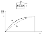
- FIG. 8 is a diagram for explaining the effect of performing feedback control using the rate control map in the present embodiment.
- Both figures (a) and (b) show changes in the cumulative value of the data size after compression coding in the unit time T in the passage of time on the horizontal axis.
- the unit time T compresses and encodes the compression unit in the sliced partial image 12 on the image plane 10 as shown in the upper part of the figure from the left end to the right end.
- the cumulative data size "A" indicates the bandwidth (upper limit of the bit rate) that can be used for communication between the server 400 and the image processing device 200 in the unit time T.
- (A) is a compression coding result by normal feedback control. In the illustrated example, it is assumed that the data size is equalized in all compression units, and as a result, the target value 14 shown by the broken line becomes linear with respect to time. On the other hand, the actual data size varies depending on the content of the image. By trying to converge this to the target value 14 by feedback control, overshoot 18 and undershoot 20 are generated as in the cumulative data size 16 shown by the solid line.
- the compression unit after falling below the target value is likely to overshoot due to feedback.
- the compression unit after exceeding the target value is likely to undershoot due to feedback.
- the overshoot state is prolonged due to a complicated image continuing at the beginning of the unit time T, the compression rate is suddenly increased at the end of the unit time T in order to keep it below the upper limit A, which is the constraint condition of the cumulative data size. Need arises. As a result, it is conceivable that an unintended change in image quality occurs depending on the position on the image, and eventually the image quality of an important part is deteriorated.
- (B) is the compression coding result when feedback control is performed using the rate control map in the present embodiment.
- a rate control map in which the tolerance for image quality degradation is set low near the center is used, and compression coding is performed from the edge of the partial image 12 that crosses the center of the image plane 10.
- the target value 22 of the cumulative data size shown by the broken line has a shape that shows a remarkable increase in a finite period in the middle of the unit time T.
- the actual cumulative data size 24 shown by the solid line can also cause overshoots and undershoots by feedback control, but even so, it increases significantly in a finite period in the middle of the unit time T. It will be a change like this. As a result, the allocation of the data size near the center of the image plane can be made larger than the other areas.
- FIG. 9 is a diagram for explaining the processing content of the image generation unit 420 that can be used to generate the rate control map.
- a unit area having the same area formed by evenly dividing an image plane is used as a pixel, and values representing each color are calculated to obtain image data.
- the illustrated example shows an area 25 of, for example, 1440 ⁇ 1440 pixels, which is one of the images for the left eye and the right eye displayed on the head-mounted display 100.
- the numerical values shown in the 25 rectangular areas indicate the reduction ratios in the horizontal and vertical directions.
- the region 30 indicated as "1x1" in the central portion is the same size in both vertical and horizontal directions, that is, the image is not reduced.
- the area 26 shown as "0.25 x 0.25" in the upper left reduces the image to 1/4 in both vertical and horizontal directions.
- the area 28 to the right of which is indicated as "0.5 x 0.25" reduces the image to 1/2 in the horizontal direction and 1/4 in the vertical direction.
- such reduction processing can be regarded as changing the area included in one pixel in the image plane in which the color values are actually obtained evenly. .. That is, the pixel value is determined in the finest unit in the "1 x 1" region, and the pixel value is determined in the area unit of 2 x 2 times in the "0.5 x 0.5" region, for example.
- FIG. 10 conceptually shows the change on the image by changing the area of the pixel.
- the image 34 is an image having an original size, and it is assumed that the area of the pixel is different for each region divided so as to be represented by a line in the rectangle.
- the image 38 is an image on the data when pixels having different areas depending on the area are represented as the same area.
- the image 36 drawn in the original image is deformed like the image 40 as a result of being reduced by a different ratio depending on the position.
- the image generation unit 420 (that is, GPU) internally holds a resolution map in which the image plane is divided according to a predetermined rule and the reduction ratio (resolution) is set as shown in FIG. 9, and the drawing target area is divided based on the resolution map. Then, by drawing each area with different resolutions, data such as image 38 is generated. As a result, the amount of calculation, the amount of memory access, and the processing time required for drawing can be reduced.
- FIG. 11 illustrates a flow of data conversion up to display of images having different resolutions depending on the area.
- the data such as the image 38 of FIG. 10 generated by the image generation unit 420 of the server 400 is compressed and encoded in that state and transferred to the image processing device 200. That is, the image generation unit 420 outputs the image 38 as it is with the number of pixels, the resolution, and the aspect ratio of the pixel area (S10), and the compression coding unit 422 compresses and encodes the image 38 as it is (S12).
- the server 400 transmits the data compressed and encoded in this way and the resolution map to the image processing device 200.
- the image data acquisition unit 240 of the image processing device 200 acquires them, and the decoding / decompression unit 242 decodes and decompresses the data and complements the pixels based on the resolution map, so that the original array of pixels, that is, the original Data with a uniform resolution having the number of pixels, the resolution, and the aspect ratio of the pixel area is generated (S14).
- the number of pixels to be transmitted from the server 400 to the image processing device 200 can be reduced.
- FIG. 12 shows another example of the flow of data conversion up to display of images having different resolutions depending on the area.
- the image generation unit 420 of the server 400 generates data as shown in the image 38 of FIG. 10, and then interpolates the pixels based on the resolution map to obtain the original pixel arrangement, that is, the number of pixels, the resolution, and the like.
- An image 41 having a uniform resolution having an aspect ratio of a pixel region is generated (S16).
- the compression coding unit 422 compresses and encodes the image 41 (S18).
- the decoding / decompression unit 242 of the image processing device 200 only decodes / decompresses the data transmitted from the server 400 to obtain an image having a uniform resolution (S20).
- the rate control map used by the compression coding unit 422 reflects the resolution map, as in the case of FIG. It can be compressed and coded with the same image quality at the same bit rate.
- the server 400 determines whether the processing procedure is as shown in FIG. 11 or as shown in FIG. 12, depending on whether or not the decoding / stretching unit 242 of the image processing device 200 supports data conversion based on the resolution map.
- the resolution map may be fixed, or the image generation unit 420 may dynamically generate it according to the content of the image. For example, the image generation unit 420 identifies the size and position of the region to be shown in detail by analyzing a moving image, maintains the resolution of the region, and sets the resolution to decrease as the distance from the region increases. May be good.
- a rate control map that reflects it may be generated in advance and stored in the rate control map storage unit 430.
- the resolution map is variable, each time the image generation unit 420 generates a resolution map, the status acquisition unit 432 of the compression coding unit 422 acquires the data, and the map generation unit 434 converts the data into a rate control map. To reflect. At this time, the map generation unit 434 corrects the rate control map prepared in advance by adding the tolerance for image quality deterioration calculated from the resolution map or multiplying the weighted value obtained from the resolution map. May be good.
- the map generation unit 434 may newly generate a rate control map from the resolution map.
- the image generation unit 420 can reduce the compression rate of the portion where the resolution is maintained, and maintain the image quality even after undergoing the compression coding process.
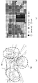
- FIG. 13 is a diagram for explaining another example of the processing content of the image generation unit 420 that can be used to generate the rate control map.
- the resolution distribution that is, the pixel area distribution is determined based on the actual image content.
- the image generation unit 420 first shows in (b) based on at least one of the distance from the center of the visual field, the magnitude of the movement of the object, the detail of the image, and the like. After generating such a pixel map, the pixel value is calculated accordingly.
- the pixel map shown in the figure represents the original pixel area on the image plane in a grid pattern, and as shown in the legend below, the higher the resolution (the smaller the pixel area), the darker the color.
- the pixel value is set to be calculated in units of "1 x 1" pixels, that is, for each original pixel.
- the pixel values should be calculated in units of "1x2" or "2x1" pixels depending on the array. Set.
- the image generation unit 420 analyzes the moving image of the drawing target, and determines the importance of the object, the size of the image, the importance of the presentation content, the precision, the color, the size of the movement, the type of texture, and whether or not it is the operation target of the user. Or, etc., to generate a pixel map. Qualitatively, the higher the importance or the higher the detail of the image, the finer the pixel unit.
- the image generation unit 420 generates a pixel map at the start of drawing a moving image, and updates the pixel map as appropriate for each partial image, each frame, every predetermined number of frames, when a scene is switched, and the like.
- the same procedure as shown in FIG. 11 or 12 is used to convert the data into data having a uniform pixel area and a uniform resolution at any stage. That is, when the decoding / stretching unit 242 of the image processing device 200 corresponds to the data conversion based on the pixel map, the server 400 compresses and encodes the image whose pixel unit differs depending on the position as it is and transfers it to the image processing device 200. Then, the decoding / stretching unit 242 of the image processing device 200 decodes / stretches the data and interpolates the pixels based on the pixel map to obtain uniform resolution data having the original number of pixels, resolution, and aspect ratio of the pixel region. To generate.
- the number of pixels to be transmitted from the server 400 to the image processing device 200 can be reduced.
- the image generation unit 420 of the server 400 originally interpolates the pixels of the image having different pixel units depending on the position based on the pixel map.
- An array of pixels that is, an image having a uniform resolution having the number of pixels, the resolution, and the aspect ratio of the pixel area is generated.
- the decoding / decompression unit 242 of the image processing device 200 acquires an image having a uniform resolution only by decoding / decompressing the data transmitted from the server 400.
- the number of pixels to be transmitted to the image processing device 200 cannot be reduced, but the number of pixels is reduced by making the rate control map used by the compression coding unit 422 reflect the pixel map. It can be compressed and coded with the same image quality at the same bit rate as when transferring image data.
- the rate control map used by the compression coding unit 422 reflects the pixel map. It can be a map.
- the situation acquisition unit 432 acquires the data each time the image generation unit 420 generates a pixel map, and the map generation unit 434 reflects the data in the rate control map.
- the method of reflection may be the same as in the case of the resolution map.
- the map generation unit 434 may further add a resolution map to generate or correct a rate control map. As a result, it is possible to set the tolerance for image quality deterioration for the combination of the area separated by the resolution map and the image distinguished by the pixel map.
- FIG. 14 is a diagram for explaining the principle of generating a rate control map based on the user's gaze point.
- the user's gaze point 292 is assumed to exist near the center in the illustrated example. Since the user wearing the head-mounted display 100 usually turns his / her face in the desired direction, the center of the display screen 290 can be regarded as the gazing point 292. However, by introducing a gazing point detector, the gazing point 292 at an arbitrary position can be detected.
- the region 294 corresponding within 5 ° with the line of sight from the pupil to the gazing point as the central axis is called a discriminative visual field, and has excellent visual functions such as visual acuity.
- the region 296 corresponding within about 30 ° in the horizontal direction and about 20 ° in the vertical direction is called an effective visual field, and information can be instantly received only by eye movement.
- the area 298 corresponding to 60 to 90 ° in the horizontal direction and 45 to 70 ° in the vertical direction is a stable gaze
- the area 299 corresponding to 100 to 200 ° in the horizontal direction and 85 to 130 ° in the vertical direction is auxiliary. The farther away from the gazing point 292, such as the visual field, the lower the ability to discriminate information.
- the discriminating power is represented by the functions 320a and 320b such that the closer to the gazing point 292, the larger the value on the plane of the display screen 290.
- the functions 320a and 320b are represented with respect to the one-dimensional positions in the horizontal and vertical directions on the plane of the display screen 290, but the actual distribution is based on the two-dimensional position coordinates on the plane. .. The lower the user's discriminating power, the smaller the effect on the visual impression even if the image quality is lowered. It should be set to.
- the status acquisition unit 432 in the compression coding unit 422 of the server 400 sequentially acquires the position coordinates of the actual gazing point on the display screen. Then, the map generation unit 434 reflects the position coordinates in the rate control map. In this case as well, the map generation unit 434 may correct the rate control map prepared in advance by adding the tolerance for image quality deterioration depending on the distance from the gazing point, or the rate control map is newly added. May be generated in. Further, it may be used as a final rate control map in combination with the tolerance of image quality deterioration obtained from the other viewpoints described above.
- the map generation unit 434 may refer to the information and reflect it in the rate control map.
- Forbidden rendering is a technology that reduces the load of drawing processing and data size by drawing the center of the field of view, which has high user identification ability, at a high resolution and at a lower resolution as the distance from the field of view is higher, as in the above-mentioned discriminant field of view. Is known (see, for example, "Foveated 3D graphics", Brian Guenter, et. Al., ACM Transactions on Graphics, Vol. 31, No. 6, Article 164, November 2012).
- the image generation unit 420 sets the resolution boundary on the image plane and the resolution reduction rate based on the position coordinates of the gazing point obtained from the gazing point acquisition unit 248 of the image processing device 200.
- a map representing the resolution distribution determined in this way on an image plane is called a forbidden rendering map.
- the status acquisition unit 432 of the compression coding unit 422 acquires the forbidden rendering map from the image generation unit 420, and the map generation unit 434 reflects the forbidden rendering map in the rate control map.
- the method of reflecting may be the same as described above.
- the same procedure as shown in FIG. 11 or 12 is used to convert the data into data having a uniform pixel area and a uniform resolution at any stage. That is, when the decoding / decompression unit 242 of the image processing device 200 supports data conversion based on the forbidden rendering map, the server 400 compresses and encodes the forbidden rendered image as it is, and causes the image processing device 200 to perform compression coding. Forward. Then, the decoding / stretching unit 242 of the image processing device 200 decodes / stretches the data and interpolates the pixels based on the forbidden rendering map to uniformly have the original number of pixels, resolution, and aspect ratio of the pixel area. Generate data of various resolutions.
- the number of pixels to be transmitted from the server 400 to the image processing device 200 can be reduced.
- the image generation unit 420 of the server 400 interpolates the pixels of the forbidden rendered image based on the pixel map. As a result, an image having an original pixel arrangement, that is, an image having a uniform resolution having the number of pixels, the resolution, and the aspect ratio of the pixel area is generated.
- the decoding / decompression unit 242 of the image processing device 200 acquires an image having a uniform resolution only by decoding / decompressing the data transmitted from the server 400. According to this procedure, the number of pixels to be transmitted to the image processing device 200 cannot be reduced, but the rate control map used by the compression coding unit 422 reflects the forbidden rendering map, so that the pixels can be transmitted. It is possible to perform compression coding with the same image quality at the same bit rate as when transferring a reduced number of image data.
- the image generation unit 420 of the server 400 may independently perform any of the resolution switching for each area, the calculation of the pixel value for a group of a plurality of pixels, and the forbidden rendering described above. One or more may be combined and carried out. When the combination is performed, the same processing as described above is performed based on the map in which the resolution map, the pixel map, and the forbidden rendering map are appropriately combined.
- FIG. 15 is a diagram for explaining the effect when the rate control map is corrected based on the content of the image and the gazing point of the user.
- the representation of the figure is the same as that of FIG. Similar to FIG. 8B, (a) is a compression coding of the sliced partial image 12 sequentially from the left end using a rate control map in which the tolerance for image quality deterioration is set low at 50a near the center of the image plane 10. Shows the cumulative value of the data size when That is, as a result of feedback control using the target value 22 based on the rate control map, the actual cumulative data size 24 is obtained as shown in the figure.
- (B) and (c) show the cumulative value of the data size when compression coding is performed using the rate control map corrected based on the content of the image and the user's gaze point as described above. However, the same target value 22 as in (a) is shown for comparison.
- (B) shows a case where the important part does not change in the vicinity of the center 50a of the image plane 10, but the importance is found to be higher in the vicinity of the center 50a in consideration of the content of the image and the gazing point. ..
- the map generation unit 434 makes a correction in the rate control map to further reduce the tolerance for image quality deterioration in the vicinity of the center 50a.
- the data size allocated to other areas can be relatively suppressed.
- the cumulative data size 52 is obtained so that the amount of increase in the cumulative data size is small at the beginning and the end of the unit time T and increases sharply in the middle finite period.
- (C) shows, for example, a case where an important object or a user's gazing point is at a position 50b to the right of the center of the image plane 10.
- the map generation unit 434 corrects the rate control map so that the region where the tolerance for image quality deterioration is low is shifted to the right side of the image plane.
- a cumulative data size 54 is obtained that increases sharply after the middle of the unit time T. In either case, it is possible to easily allocate a larger data size to an important area after suppressing the cumulative value of the data size per unit time T to the upper limit A or less.
- the map generation unit 434 estimates the data size for each compression unit by having the compression coding processing unit 436 actually compress and encode the image as a temporary compression process, and based on the result, the rate control map. May be corrected.
- the compression coding processing unit 436 may speed up the estimation of the data size by simply performing the compression coding by the following method. That is, the compression coding processing unit 436 may perform the temporary compression processing after lowering the resolution of the image generated by the image generation unit 420.
- the compression coding processing unit 436 prepares a plurality of reduced images in which the resolution of the image generated by the image generation unit 420 is reduced by a ratio of 1/2, 1/4, 1/8, etc., and has the lowest resolution. Temporary compression processing may be performed in order from the side. The lower the image resolution, the faster the estimation of the data size by temporary compression. The compression coding processing unit 436 repeats the estimation of the data size in order from the low resolution side, and the difference between the data size estimated at a certain resolution and the data size estimated at the immediately preceding resolution is equal to or less than a predetermined threshold value. For example, the temporary compression process may be terminated.
- the compression coding processing unit 436 may use a rectangular region cut out from each compression unit as a sample region and perform temporary compression processing of the sample region without lowering the resolution. In this case, it is possible to prevent the data size estimation accuracy from being lowered due to the loss of features such as fineness and high frequency components by lowering the resolution.
- the compression coding processing unit 436 samples the number of samples in the region where the tolerance for image quality deterioration is equal to or less than a predetermined value in the rate control map, that is, the compression unit determined to be important from the viewpoint of the image content and the user's gazing point. May be increased.
- the compression rate can be kept low and the data size can be estimated accurately for the parts that easily affect the data size.
- the compression coding processing unit 436 may omit the temporary compression processing in the region where the deterioration of the image quality is allowed to be a predetermined value or more in the rate control map.
- the map generation unit 434 refers to the estimation of the data size for each compression unit thus obtained, and corrects the rate control map.
- the map generation unit 434 relatively increases the tolerance for image quality deterioration in the areas other than those in the rate control map. As a result, the same state as in (b) and (c) in the figure can be obtained. As a result, as described above, the cumulative value of the data size per unit time T can be suppressed to the upper limit A or less, and more data size can be allocated to the required area.
- the correction of the rate control map by the temporary compression processing can also be combined with the correction from the other viewpoints described above.
- the time change of the cumulative data size shown in FIGS. 8 and 15 was premised on the progress of compression coding so as to traverse from the left end to the right end of the sliced partial image obtained by dividing the image plane in the horizontal direction. ..
- the area to which a large amount of data size is to be allocated may be compressed and coded first in the unit time T so as to be excluded from the target of data size adjustment at the end of the unit time T.
- the data size can be allocated to the area where the image quality maintenance is prioritized more reliably and stably.
- FIG. 16 illustrates a change in the cumulative data size when the processing order of compression coding is variable in the partial image.
- the representation of the figure is the same as in FIGS. 8 and 15.
- the compression coding processing unit 436 moves in the left-right direction from the vicinity of the center 50a as shown by an arrow in the upper part of the figure.
- Advance compression coding In this case, even if the same rate control map as before is used, the target value 56 shown by the broken line has a shape in which the amount of change is large from the beginning of the unit time T and gradually becomes gentle.
- the actual cumulative data size 58 shown by the solid line also changes in the same way.
- the cumulative data size is likely to exceed the upper limit A of the bit rate, and even if the compression rate is controlled to be increased, the processing target at that time is an area in which image quality is not emphasized. The effect on the appearance can be reduced.
- the compression coding processing unit 436 buffers the compression unit for which compression coding has been completed by a maximum of one partial image, restores the order on the original image, and then packets the compression unit as partial image data 424. Output to.
- the server 400 may transmit the partial image data in the compressed coded order, and the image processing apparatus 200 may return the data to the original order.
- the server 400 transmits a processing order map showing the compression processing order of the compression unit in each partial image, and thus the transmission order, together with the data of the partial image.
- the decoding / decompression unit 242 of the image processing device 200 decodes / decompresses each compression unit in the order of transmission from the server 400, and buffers up to one partial image to return to the original order on the image. ..
- the decoding / decompression unit 242 of the image processing device 200 decodes / decompresses each compression unit in the order of transmission from the server 400, and buffers up to one partial image to return to the original order on the image. ..
- 50a near the center of the image plane 10 is set as an important region, and the compression coding is progressed in the left-right direction with that as the starting point, but the starting point and the progress direction of the compression coding process are not particularly limited.
- the compression unit with the lower tolerance for image quality deterioration shown in the rate control map is basically to give higher priority in the processing order, and the compression processing order is set in consideration of the processing efficiency. You just have to decide.
- the constraint of the feedback control may be relaxed in the early stage of the unit time T, and the control parameter may be changed with time so as to tighten the constraint toward the final stage. For example, when PID control is performed, the P parameter (proportional component) and the D parameter (differential component) are increased with the passage of time.
- control parameter may be continuously changed with the passage of time, or the unit time T may be divided into a plurality of periods such as the early stage, the middle stage, and the final stage, and the control parameter may be set for each period. It may be changed discontinuously.
- FIG. 17 schematically shows an example of setting the processing order when the order of the compression coding processing is variable in the partial image.
- the head-mounted display 100 is used as the display destination, and the frame including the images for the left eye and the right eye is compressed and encoded. That is, the processing order map 60 compresses and encodes the plane of one frame composed of the area 62a for the left eye and the area 62b for the right eye with respect to the compression unit formed by dividing the plane into 11 in the vertical direction and 6 in the horizontal direction.
- the processing order is indicated by a number.
- the compression unit for one horizontal row is used as a partial image.
- the areas 64a and 64b surrounded by the dotted lines indicate the user's visible area in the head-mounted display 100, and the unit area not included in the area 64a and 64b is excluded from the compression process.
- the compression coding processing unit 436 skips the compression processing for the first partial image in the uppermost stage, and performs the compression processing for the second partial image below it only in the compression units numbered in the order of the numbers. ..
- the compression coding processing unit 436 restores the order of the buffered data and outputs the data to the packetization unit 424. ..
- the third partial image, the fourth partial image, and the fifth partial image below it are compressed and encoded in numerical order and then output in units of partial images.
- the sixth partial image at the bottom skips the compression process.
- the data in the unit area of "2" can be composed of a difference image in which the unit area of "1" having a high similarity to it is used as a reference image, and the data size can be remarkably suppressed.
- the compression coding processing unit 436 refers to the rate control map, gives a high priority to the compression unit having a low tolerance for image quality deterioration for each partial image, and gives high priority to the image similarity and the efficiency of the processing order.
- the processing order map 60 is created in consideration of the above viewpoints, and then compression coding is performed.
- the compression coding processing unit 436 may generate the processing order map 60 by referring to the rate control map finally obtained from various viewpoints.
- the rate control map showing the tolerance for image quality deterioration is referred to, and the compression ratio is preferentially set for the region with high tolerance. Control to raise.
- the rate control map deteriorates the image quality in parts that are easily visible to the user, parts that are important as the content of the image, parts that include the actual gazing point, and parts that are estimated to be difficult to reduce the data size due to temporary compression processing. Set to lower the tolerance of.
- the cumulative data size per unit time can be kept below a certain value while maintaining the image quality by preferentially allocating a large amount of data size to those parts.
- the control of the data size using the rate control map is performed when a predetermined condition for significantly reducing the data size is satisfied in the normal control that does not refer to the map. As a result, it is possible to prevent the image quality from being unnecessarily deteriorated due to excessive data compression, and to reduce the influence on the load of the compression coding process.
- the delay time until display can be reduced by pipeline processing the data after compression coding in units of partial images formed by dividing one frame.
- the cumulative data size per unit time is kept below the upper limit of the bit rate, and the data size is stabilized for the important region. Assigned to.
- the stability of data size allocation can be further improved.
- the server 400 compresses and encodes the frame data with the distribution based on the rate control map, thereby achieving both image quality and data size reduction.
- the data size to be transmitted can be reduced while suppressing the influence on the visually recognized image quality.
- FIG. 18 shows the functional blocks of the server 400a and the image processing device 200a of the present embodiment. The basic configuration of these devices and the configuration of the image display system configured by the devices are the same as those in the first embodiment. Further, in the figure, the blocks having the same functions as those in FIG. 6 are designated by the same reference numerals, and the description thereof will be omitted as appropriate.
- the server 400 includes an image generation unit 420a, a compression coding unit 422, a packetization unit 424, and a communication unit 426.
- the image generation unit 420a draws an image by changing the resolution with respect to the position of the moving image on the frame plane.
- the image generation unit 420a includes a resolution map storage unit 450, a situation acquisition unit 452, a map generation unit 454, and a drawing unit 456.
- the resolution map storage unit 450 stores a resolution map showing the distribution of resolution with respect to the plane of the frame as shown in FIG.
- the situation acquisition unit 452 acquires information related to various situations that can affect the distribution of resolution.
- the situation acquisition unit 452 acquires, for example, information related to the position of the user's gazing point, which is used when performing forbidden rendering.
- the situation acquisition unit 452 identifies an edge of the field of view, a region where the movement of the object is small, a region with low precision, etc. by analyzing the image to be drawn.
- the map generation unit 454 generates a map showing the distribution of resolution with respect to the plane of the frame based on the information acquired by the situation acquisition unit 452. For example, the map generation unit 454 generates a forbidden rendering map whose resolution decreases as the distance from the user's gazing point increases.
- the map generation unit 454 sets a group of pixels for calculating one pixel value as shown in FIG. 13 based on the edge of the field of view, the region where the movement of the object is small, the region where the density is low, and the like. Generate a pixel map represented on a plane.
- the drawing unit 456 changes the resolution depending on the position in the frame plane based on at least one of the resolution map stored in the resolution map storage unit 450, the forbidden rendering map generated by the map generation unit 454, and the pixel map. Draw an image.
- these maps are collectively referred to as "resolution maps”.
- the map generation unit 454 reads out the static resolution map stored in the resolution map storage unit 450, and corrects the resolution so as to reflect the distribution of the resolution and the group of pixels determined from other viewpoints, so as to be final. Resolution map may be generated.
- the compression coding unit 422a compresses and encodes the image data generated by the image generation unit 420.
- the compression rate control function based on the rate control map in the compression coding unit 422 of the first embodiment can be omitted.
- the functions of the packetizing unit 424 and the communication unit 426 are the same as those in the first embodiment. However, the packetization unit 424 associates the resolution map adopted by the image generation unit 420a for drawing the image with the frame data.
- the communication unit 426 sequentially transmits the data to the image processing device 200a in units of partial images.
- the image processing device 200a includes an image data acquisition unit 240, a decoding / decompression unit 242a, an image processing unit 244, a display control unit 246, and a gazing point acquisition unit 248.
- the function of the image data acquisition unit 240 is the same as that of the first embodiment.
- the image data acquisition unit 240 acquires a resolution map from the server 400 together with the compressed coded partial image data.
- the decoding / decompression unit 242a decodes / decompresses the data of the compression-encoded partial image as in the first embodiment.
- the decoding / stretching unit 242a includes a resolution conversion unit 243.
- the resolution conversion unit 243 restores the original pixel sequence by interpolating the pixels using the resolution map transmitted from the server 400, and converts the image into an image having a uniform resolution.
- the decoding / stretching unit 242a decodes and stretches the data that has been compressed and encoded while changing the resolution on the image plane, and then decodes and stretches the data, and then interpolates the pixels based on the resolution map. , Generates data with a uniform resolution having the original number of pixels, resolution, and aspect ratio of the pixel area.
- the functions of the image processing unit 244, the display control unit 246, and the gaze point acquisition unit 248 may be the same as those in the first embodiment.
- the server draws an image by changing the resolution depending on the position of the moving image on the frame plane, and then streams and transfers the image together with the resolution map showing the distribution of the resolution.
- the image processing device on the client side converts the frame resolution to the original uniform state based on the resolution map, and then outputs the image to the display panel.
- the server maintains the drawing resolution and the image quality for the center of the image that the user can easily gaze at, the actual gaze point, or the part that is conspicuous in the content of the image.
- the influence on the visual image quality is small, and the number of pixels to be transmitted from the server to the image processing device, and eventually the data size can be reduced.
- the present invention can be used for various information processing devices such as servers, image display devices, head-mounted displays, game devices, mobile terminals, and personal computers, and image display systems including any of them.
- 1 image display system 100 head mount display, 200 image processing device, 240 image data acquisition unit, 242 decoding / decompression unit, 244 image processing unit, 246 display control unit, 248 gaze point acquisition unit, 302 flat plate display, 400 server, 420 image generation unit, 422 compression coding unit, 424 packetization unit, 426 communication unit, 430 rate control map storage unit, 432 status acquisition unit, 434 map generation unit, 436 compression coding processing unit, 440 target value setting unit, 441 switching unit, 442 comparison unit, 444 compression unit, 446 compressed data size acquisition unit, 452 status acquisition unit, 454 map generation unit, 456 drawing unit.
Landscapes
- Engineering & Computer Science (AREA)
- Physics & Mathematics (AREA)
- Theoretical Computer Science (AREA)
- General Physics & Mathematics (AREA)
- Multimedia (AREA)
- General Engineering & Computer Science (AREA)
- Human Computer Interaction (AREA)
- Optics & Photonics (AREA)
- Signal Processing (AREA)
- Quality & Reliability (AREA)
- Computer Vision & Pattern Recognition (AREA)
- Health & Medical Sciences (AREA)
- General Health & Medical Sciences (AREA)
- Ophthalmology & Optometry (AREA)
- Compression Or Coding Systems Of Tv Signals (AREA)
- Controls And Circuits For Display Device (AREA)
Priority Applications (3)
| Application Number | Priority Date | Filing Date | Title |
|---|---|---|---|
| PCT/JP2020/014681 WO2021199205A1 (ja) | 2020-03-30 | 2020-03-30 | 画像データ転送装置、画像表示システム、および画像データ転送方法 |
| US17/911,256 US12387381B2 (en) | 2020-03-30 | 2020-03-30 | Image data transfer apparatus, image display system, and image data transfer method |
| JP2022512938A JP7362903B2 (ja) | 2020-03-30 | 2020-03-30 | 画像データ転送装置、画像表示システム、および画像データ転送方法 |
Applications Claiming Priority (1)
| Application Number | Priority Date | Filing Date | Title |
|---|---|---|---|
| PCT/JP2020/014681 WO2021199205A1 (ja) | 2020-03-30 | 2020-03-30 | 画像データ転送装置、画像表示システム、および画像データ転送方法 |
Publications (1)
| Publication Number | Publication Date |
|---|---|
| WO2021199205A1 true WO2021199205A1 (ja) | 2021-10-07 |
Family
ID=77929800
Family Applications (1)
| Application Number | Title | Priority Date | Filing Date |
|---|---|---|---|
| PCT/JP2020/014681 Ceased WO2021199205A1 (ja) | 2020-03-30 | 2020-03-30 | 画像データ転送装置、画像表示システム、および画像データ転送方法 |
Country Status (3)
| Country | Link |
|---|---|
| US (1) | US12387381B2 (https=) |
| JP (1) | JP7362903B2 (https=) |
| WO (1) | WO2021199205A1 (https=) |
Cited By (3)
| Publication number | Priority date | Publication date | Assignee | Title |
|---|---|---|---|---|
| JP2024145685A (ja) * | 2023-03-31 | 2024-10-15 | 株式会社日立製作所 | 計算機システム及びデータの圧縮方法 |
| CN119342219A (zh) * | 2024-12-19 | 2025-01-21 | 长沙超创电子科技有限公司 | 一种端到端低延时的图像传输方法 |
| CN119946286A (zh) * | 2025-04-08 | 2025-05-06 | 杭州海康威视数字技术股份有限公司 | 一种图像处理方法、装置及设备 |
Families Citing this family (12)
| Publication number | Priority date | Publication date | Assignee | Title |
|---|---|---|---|---|
| JP7392105B2 (ja) * | 2019-07-28 | 2023-12-05 | グーグル エルエルシー | 没入型ビデオコンテンツをフォービエイテッドメッシュを用いてレンダリングするための方法、システム、および媒体 |
| WO2021199128A1 (ja) * | 2020-03-30 | 2021-10-07 | 株式会社ソニー・インタラクティブエンタテインメント | 画像データ転送装置、画像生成方法およびコンピュータプログラム |
| CN113920010B (zh) * | 2020-07-10 | 2025-07-15 | 华为技术有限公司 | 图像帧的超分辨率实现方法和装置 |
| WO2022219877A1 (ja) * | 2021-04-12 | 2022-10-20 | ソニーグループ株式会社 | 情報処理装置、情報処理方法およびプログラム |
| US20230237730A1 (en) * | 2022-01-21 | 2023-07-27 | Meta Platforms Technologies, Llc | Memory structures to support changing view direction |
| WO2023230965A1 (zh) * | 2022-06-01 | 2023-12-07 | 京东方科技集团股份有限公司 | 显示方法及装置 |
| US12238369B2 (en) * | 2022-09-30 | 2025-02-25 | Cypress Semiconductor Corporation | System and method for high resolution, high frame rate video capture using a USB port |
| CN116743180B (zh) * | 2023-08-08 | 2024-02-13 | 东莞市欧派奇电子科技有限公司 | 一种储能电源数据智能存储方法 |
| US20250245932A1 (en) * | 2024-01-26 | 2025-07-31 | Samsung Electronics Co., Ltd. | Tile processing and transformation for video see-through (vst) extended reality (xr) |
| US20250299371A1 (en) * | 2024-03-22 | 2025-09-25 | Microsoft Technology Licensing, Llc | Image compression |
| WO2026044530A1 (en) * | 2024-08-28 | 2026-03-05 | Qualcomm Incorporated | Queue management for setting storage in performing image processing tasks |
| CN120125603B (zh) * | 2025-05-14 | 2025-07-11 | 南京维赛客网络科技有限公司 | 基于ai的分割虚拟图像并显示的方法、系统及存储介质 |
Citations (3)
| Publication number | Priority date | Publication date | Assignee | Title |
|---|---|---|---|---|
| JP2002247602A (ja) * | 2001-02-15 | 2002-08-30 | Mixed Reality Systems Laboratory Inc | 画像生成装置及びその制御方法並びにそのコンピュータプログラム |
| JP2002300581A (ja) * | 2001-03-29 | 2002-10-11 | Matsushita Electric Ind Co Ltd | 映像符号化装置、及び映像符号化プログラム |
| WO2018125579A1 (en) * | 2016-12-29 | 2018-07-05 | Sony Interactive Entertainment Inc. | Foveated video link for vr, low latency wireless hmd video streaming with gaze tracking |
Family Cites Families (13)
| Publication number | Priority date | Publication date | Assignee | Title |
|---|---|---|---|---|
| JP4898589B2 (ja) | 2007-07-26 | 2012-03-14 | 株式会社日立製作所 | 画像圧縮方法、および、画像処理装置 |
| US12153156B2 (en) * | 2017-01-13 | 2024-11-26 | Origin Research Wireless, Inc. | Method, apparatus, and system for wireless monitoring with improved accuracy |
| US20230188384A1 (en) * | 2020-05-10 | 2023-06-15 | David N. Claffey | Method, apparatus, and system for wireless sensing based on multiple groups of wireless devices |
| WO2019178404A1 (en) * | 2018-03-14 | 2019-09-19 | The Regents Of The University Of California | Automated cardiac function assessment by echocardiography |
| US12580063B2 (en) * | 2018-12-21 | 2026-03-17 | Siemens Healthineers International Ag | Methods and systems for radiotherapy treatment planning based on deep transfer learning |
| EP3924933B1 (en) * | 2019-03-21 | 2026-02-25 | Huawei Technologies Co., Ltd. | Image processor |
| US20200395117A1 (en) * | 2019-06-14 | 2020-12-17 | Cycle Clarity, LLC | Adaptive image processing method and system in assisted reproductive technologies |
| US11514573B2 (en) * | 2019-11-27 | 2022-11-29 | Shanghai United Imaging Intelligence Co., Ltd. | Estimating object thickness with neural networks |
| US11615184B2 (en) * | 2020-01-31 | 2023-03-28 | Palo Alto Networks, Inc. | Building multi-representational learning models for static analysis of source code |
| US11550911B2 (en) * | 2020-01-31 | 2023-01-10 | Palo Alto Networks, Inc. | Multi-representational learning models for static analysis of source code |
| WO2022046463A1 (en) * | 2020-08-24 | 2022-03-03 | Ventana Medical Systems, Inc. | Histological stain pattern and artifacts classification using few-shot learning |
| US12573238B2 (en) * | 2021-12-29 | 2026-03-10 | Elm | Biometric facial recognition and liveness detector using AI computer vision |
| US12462335B2 (en) * | 2022-03-03 | 2025-11-04 | Rensselaer Polytechnic Institute | Systems and methods for multi-modal multi-dimensional image registration |
-
2020
- 2020-03-30 US US17/911,256 patent/US12387381B2/en active Active
- 2020-03-30 WO PCT/JP2020/014681 patent/WO2021199205A1/ja not_active Ceased
- 2020-03-30 JP JP2022512938A patent/JP7362903B2/ja active Active
Patent Citations (3)
| Publication number | Priority date | Publication date | Assignee | Title |
|---|---|---|---|---|
| JP2002247602A (ja) * | 2001-02-15 | 2002-08-30 | Mixed Reality Systems Laboratory Inc | 画像生成装置及びその制御方法並びにそのコンピュータプログラム |
| JP2002300581A (ja) * | 2001-03-29 | 2002-10-11 | Matsushita Electric Ind Co Ltd | 映像符号化装置、及び映像符号化プログラム |
| WO2018125579A1 (en) * | 2016-12-29 | 2018-07-05 | Sony Interactive Entertainment Inc. | Foveated video link for vr, low latency wireless hmd video streaming with gaze tracking |
Non-Patent Citations (3)
| Title |
|---|
| GEISLER W S , PERRY J S: "A real-time foveated multiresolution system for low-bandwidth video communication", PROCEEDINGS OF SPIE, vol. 3299, 1 January 1998 (1998-01-01), US , pages 294 - 305, XP002636639, ISBN: 978-1-62841-730-2, DOI: 10.1117/12.320120 * |
| JIHOON RYOO, KIWON YUN, DIMITRIS SAMARAS, SAMIR R. DAS, GREGORY ZELINSKY: "Design and evaluation of a foveated video streaming service for commodity client devices", PROCEEDINGS OF THE 7TH INTERNATIONAL CONFERENCE ON MULTIMEDIA SYSTEMS, MMSYS , 1 January 2016 (2016-01-01) - 13 May 2016 (2016-05-13), New York, New York, USA , pages 1 - 11, XP055523235, ISBN: 978-1-4503-4297-1, DOI: 10.1145/2910017.2910592 * |
| ROMERO-RONDON, M. F. ET AL.: "Foveated streaming ofvirtual reality videos", MMSYS, 18 June 2018 (2018-06-18), pages 494 - 497, XP055914785 * |
Cited By (3)
| Publication number | Priority date | Publication date | Assignee | Title |
|---|---|---|---|---|
| JP2024145685A (ja) * | 2023-03-31 | 2024-10-15 | 株式会社日立製作所 | 計算機システム及びデータの圧縮方法 |
| CN119342219A (zh) * | 2024-12-19 | 2025-01-21 | 长沙超创电子科技有限公司 | 一种端到端低延时的图像传输方法 |
| CN119946286A (zh) * | 2025-04-08 | 2025-05-06 | 杭州海康威视数字技术股份有限公司 | 一种图像处理方法、装置及设备 |
Also Published As
| Publication number | Publication date |
|---|---|
| US12387381B2 (en) | 2025-08-12 |
| US20230099405A1 (en) | 2023-03-30 |
| JPWO2021199205A1 (https=) | 2021-10-07 |
| JP7362903B2 (ja) | 2023-10-17 |
Similar Documents
| Publication | Publication Date | Title |
|---|---|---|
| JP7362903B2 (ja) | 画像データ転送装置、画像表示システム、および画像データ転送方法 | |
| JP7837134B2 (ja) | 画像データ転送装置および画像圧縮方法 | |
| US11290699B2 (en) | View direction based multilevel low bandwidth techniques to support individual user experiences of omnidirectional video | |
| WO2021065628A1 (ja) | 画像処理装置、画像データ転送装置、画像処理方法、および画像データ転送方法 | |
| JP7389602B2 (ja) | 画像表示システム、画像処理装置、および動画配信方法 | |
| JP7491676B2 (ja) | 画像データ転送装置および画像圧縮方法 | |
| JP7555698B2 (ja) | 画像データ転送装置および画像データ転送方法 | |
| US12088932B2 (en) | Methods and apparatus for encoding, communicating and/or using images | |
| CN112655210A (zh) | 使用多区段重采样的快速目标区域编码 | |
| CN112470484B (zh) | 用于流式传输视频的方法和设备 | |
| WO2021065627A1 (ja) | 画像処理装置、画像表示システム、画像データ転送装置、および画像処理方法 | |
| JP7496677B2 (ja) | 画像データ転送装置、画像表示システム、および画像圧縮方法 | |
| WO2021199184A1 (ja) | 画像表示システム、画像処理装置、画像表示方法、およびコンピュータプログラム | |
| US20240267559A1 (en) | Information processing apparatus and information processing method | |
| US12034786B2 (en) | Image processing device, image data transfer device, and image generation method | |
| WO2021193362A1 (ja) | 画像処理装置および画像処理方法 | |
| TW202218421A (zh) | 內容顯示處理 | |
| JP7393267B2 (ja) | 画像データ転送装置、画像表示システム、および画像データ転送方法 | |
| CN119563158A (zh) | 扩展现实编码 |
Legal Events
| Date | Code | Title | Description |
|---|---|---|---|
| 121 | Ep: the epo has been informed by wipo that ep was designated in this application |
Ref document number: 20929444 Country of ref document: EP Kind code of ref document: A1 |
|
| ENP | Entry into the national phase |
Ref document number: 2022512938 Country of ref document: JP Kind code of ref document: A |
|
| NENP | Non-entry into the national phase |
Ref country code: DE |
|
| 122 | Ep: pct application non-entry in european phase |
Ref document number: 20929444 Country of ref document: EP Kind code of ref document: A1 |
|
| WWG | Wipo information: grant in national office |
Ref document number: 17911256 Country of ref document: US |