WO2021199115A1 - 音響システム - Google Patents
音響システム Download PDFInfo
- Publication number
- WO2021199115A1 WO2021199115A1 PCT/JP2020/014471 JP2020014471W WO2021199115A1 WO 2021199115 A1 WO2021199115 A1 WO 2021199115A1 JP 2020014471 W JP2020014471 W JP 2020014471W WO 2021199115 A1 WO2021199115 A1 WO 2021199115A1
- Authority
- WO
- WIPO (PCT)
- Prior art keywords
- speaker unit
- sound
- speaker
- acoustic
- user
- Prior art date
- Legal status (The legal status is an assumption and is not a legal conclusion. Google has not performed a legal analysis and makes no representation as to the accuracy of the status listed.)
- Ceased
Links
Images







Classifications
-
- H—ELECTRICITY
- H04—ELECTRIC COMMUNICATION TECHNIQUE
- H04R—LOUDSPEAKERS, MICROPHONES, GRAMOPHONE PICK-UPS OR LIKE ACOUSTIC ELECTROMECHANICAL TRANSDUCERS; ELECTRIC HEARING AIDS; PUBLIC ADDRESS SYSTEMS
- H04R5/00—Stereophonic arrangements
- H04R5/02—Spatial or constructional arrangements of loudspeakers
- H04R5/023—Spatial or constructional arrangements of loudspeakers in a chair, pillow
-
- G—PHYSICS
- G10—MUSICAL INSTRUMENTS; ACOUSTICS
- G10K—SOUND-PRODUCING DEVICES; METHODS OR DEVICES FOR PROTECTING AGAINST, OR FOR DAMPING, NOISE OR OTHER ACOUSTIC WAVES IN GENERAL; ACOUSTICS NOT OTHERWISE PROVIDED FOR
- G10K11/00—Methods or devices for transmitting, conducting or directing sound in general; Methods or devices for protecting against, or for damping, noise or other acoustic waves in general
- G10K11/16—Methods or devices for protecting against, or for damping, noise or other acoustic waves in general
- G10K11/175—Methods or devices for protecting against, or for damping, noise or other acoustic waves in general using interference effects; Masking sound
- G10K11/178—Methods or devices for protecting against, or for damping, noise or other acoustic waves in general using interference effects; Masking sound by electro-acoustically regenerating the original acoustic waves in anti-phase
- G10K11/1787—General system configurations
- G10K11/17879—General system configurations using both a reference signal and an error signal
- G10K11/17881—General system configurations using both a reference signal and an error signal the reference signal being an acoustic signal, e.g. recorded with a microphone
-
- G—PHYSICS
- G10—MUSICAL INSTRUMENTS; ACOUSTICS
- G10K—SOUND-PRODUCING DEVICES; METHODS OR DEVICES FOR PROTECTING AGAINST, OR FOR DAMPING, NOISE OR OTHER ACOUSTIC WAVES IN GENERAL; ACOUSTICS NOT OTHERWISE PROVIDED FOR
- G10K11/00—Methods or devices for transmitting, conducting or directing sound in general; Methods or devices for protecting against, or for damping, noise or other acoustic waves in general
- G10K11/16—Methods or devices for protecting against, or for damping, noise or other acoustic waves in general
- G10K11/175—Methods or devices for protecting against, or for damping, noise or other acoustic waves in general using interference effects; Masking sound
- G10K11/178—Methods or devices for protecting against, or for damping, noise or other acoustic waves in general using interference effects; Masking sound by electro-acoustically regenerating the original acoustic waves in anti-phase
- G10K11/1785—Methods, e.g. algorithms; Devices
- G10K11/17857—Geometric disposition, e.g. placement of microphones
-
- G—PHYSICS
- G10—MUSICAL INSTRUMENTS; ACOUSTICS
- G10K—SOUND-PRODUCING DEVICES; METHODS OR DEVICES FOR PROTECTING AGAINST, OR FOR DAMPING, NOISE OR OTHER ACOUSTIC WAVES IN GENERAL; ACOUSTICS NOT OTHERWISE PROVIDED FOR
- G10K11/00—Methods or devices for transmitting, conducting or directing sound in general; Methods or devices for protecting against, or for damping, noise or other acoustic waves in general
- G10K11/16—Methods or devices for protecting against, or for damping, noise or other acoustic waves in general
- G10K11/175—Methods or devices for protecting against, or for damping, noise or other acoustic waves in general using interference effects; Masking sound
- G10K11/178—Methods or devices for protecting against, or for damping, noise or other acoustic waves in general using interference effects; Masking sound by electro-acoustically regenerating the original acoustic waves in anti-phase
- G10K11/1787—General system configurations
- G10K11/17879—General system configurations using both a reference signal and an error signal
-
- G—PHYSICS
- G10—MUSICAL INSTRUMENTS; ACOUSTICS
- G10K—SOUND-PRODUCING DEVICES; METHODS OR DEVICES FOR PROTECTING AGAINST, OR FOR DAMPING, NOISE OR OTHER ACOUSTIC WAVES IN GENERAL; ACOUSTICS NOT OTHERWISE PROVIDED FOR
- G10K11/00—Methods or devices for transmitting, conducting or directing sound in general; Methods or devices for protecting against, or for damping, noise or other acoustic waves in general
- G10K11/16—Methods or devices for protecting against, or for damping, noise or other acoustic waves in general
- G10K11/175—Methods or devices for protecting against, or for damping, noise or other acoustic waves in general using interference effects; Masking sound
- G10K11/178—Methods or devices for protecting against, or for damping, noise or other acoustic waves in general using interference effects; Masking sound by electro-acoustically regenerating the original acoustic waves in anti-phase
- G10K11/1787—General system configurations
- G10K11/17885—General system configurations additionally using a desired external signal, e.g. pass-through audio such as music or speech
-
- H—ELECTRICITY
- H04—ELECTRIC COMMUNICATION TECHNIQUE
- H04R—LOUDSPEAKERS, MICROPHONES, GRAMOPHONE PICK-UPS OR LIKE ACOUSTIC ELECTROMECHANICAL TRANSDUCERS; ELECTRIC HEARING AIDS; PUBLIC ADDRESS SYSTEMS
- H04R1/00—Details of transducers, loudspeakers or microphones
- H04R1/02—Casings; Cabinets ; Supports therefor; Mountings therein
- H04R1/025—Arrangements for fixing loudspeaker transducers, e.g. in a box, furniture
-
- H—ELECTRICITY
- H04—ELECTRIC COMMUNICATION TECHNIQUE
- H04R—LOUDSPEAKERS, MICROPHONES, GRAMOPHONE PICK-UPS OR LIKE ACOUSTIC ELECTROMECHANICAL TRANSDUCERS; ELECTRIC HEARING AIDS; PUBLIC ADDRESS SYSTEMS
- H04R1/00—Details of transducers, loudspeakers or microphones
- H04R1/10—Earpieces; Attachments therefor ; Earphones; Monophonic headphones
- H04R1/1083—Reduction of ambient noise
-
- G—PHYSICS
- G10—MUSICAL INSTRUMENTS; ACOUSTICS
- G10K—SOUND-PRODUCING DEVICES; METHODS OR DEVICES FOR PROTECTING AGAINST, OR FOR DAMPING, NOISE OR OTHER ACOUSTIC WAVES IN GENERAL; ACOUSTICS NOT OTHERWISE PROVIDED FOR
- G10K2210/00—Details of active noise control [ANC] covered by G10K11/178 but not provided for in any of its subgroups
- G10K2210/10—Applications
- G10K2210/128—Vehicles
- G10K2210/1281—Aircraft, e.g. spacecraft, airplane or helicopter
-
- G—PHYSICS
- G10—MUSICAL INSTRUMENTS; ACOUSTICS
- G10K—SOUND-PRODUCING DEVICES; METHODS OR DEVICES FOR PROTECTING AGAINST, OR FOR DAMPING, NOISE OR OTHER ACOUSTIC WAVES IN GENERAL; ACOUSTICS NOT OTHERWISE PROVIDED FOR
- G10K2210/00—Details of active noise control [ANC] covered by G10K11/178 but not provided for in any of its subgroups
- G10K2210/30—Means
- G10K2210/301—Computational
- G10K2210/3046—Multiple acoustic inputs, multiple acoustic outputs
-
- G—PHYSICS
- G10—MUSICAL INSTRUMENTS; ACOUSTICS
- G10K—SOUND-PRODUCING DEVICES; METHODS OR DEVICES FOR PROTECTING AGAINST, OR FOR DAMPING, NOISE OR OTHER ACOUSTIC WAVES IN GENERAL; ACOUSTICS NOT OTHERWISE PROVIDED FOR
- G10K2210/00—Details of active noise control [ANC] covered by G10K11/178 but not provided for in any of its subgroups
- G10K2210/30—Means
- G10K2210/321—Physical
- G10K2210/3219—Geometry of the configuration
-
- G—PHYSICS
- G10—MUSICAL INSTRUMENTS; ACOUSTICS
- G10K—SOUND-PRODUCING DEVICES; METHODS OR DEVICES FOR PROTECTING AGAINST, OR FOR DAMPING, NOISE OR OTHER ACOUSTIC WAVES IN GENERAL; ACOUSTICS NOT OTHERWISE PROVIDED FOR
- G10K2210/00—Details of active noise control [ANC] covered by G10K11/178 but not provided for in any of its subgroups
- G10K2210/30—Means
- G10K2210/321—Physical
- G10K2210/3221—Headrests, seats or the like, for personal ANC systems
-
- G—PHYSICS
- G10—MUSICAL INSTRUMENTS; ACOUSTICS
- G10K—SOUND-PRODUCING DEVICES; METHODS OR DEVICES FOR PROTECTING AGAINST, OR FOR DAMPING, NOISE OR OTHER ACOUSTIC WAVES IN GENERAL; ACOUSTICS NOT OTHERWISE PROVIDED FOR
- G10K2210/00—Details of active noise control [ANC] covered by G10K11/178 but not provided for in any of its subgroups
- G10K2210/30—Means
- G10K2210/321—Physical
- G10K2210/3229—Transducers
-
- H—ELECTRICITY
- H04—ELECTRIC COMMUNICATION TECHNIQUE
- H04R—LOUDSPEAKERS, MICROPHONES, GRAMOPHONE PICK-UPS OR LIKE ACOUSTIC ELECTROMECHANICAL TRANSDUCERS; ELECTRIC HEARING AIDS; PUBLIC ADDRESS SYSTEMS
- H04R2460/00—Details of hearing devices, i.e. of ear- or headphones covered by H04R1/10 or H04R5/033 but not provided for in any of their subgroups, or of hearing aids covered by H04R25/00 but not provided for in any of its subgroups
- H04R2460/01—Hearing devices using active noise cancellation
-
- H—ELECTRICITY
- H04—ELECTRIC COMMUNICATION TECHNIQUE
- H04R—LOUDSPEAKERS, MICROPHONES, GRAMOPHONE PICK-UPS OR LIKE ACOUSTIC ELECTROMECHANICAL TRANSDUCERS; ELECTRIC HEARING AIDS; PUBLIC ADDRESS SYSTEMS
- H04R2499/00—Aspects covered by H04R or H04S not otherwise provided for in their subgroups
- H04R2499/10—General applications
- H04R2499/13—Acoustic transducers and sound field adaptation in vehicles
Definitions
- the present invention relates to a technique for reducing noise in an aircraft.
- Non-Patent Document 1 Conventionally, users have used earphones or headphones having a noise canceling function when they are concerned about noise when watching movies / music on an airplane (see Non-Patent Document 1).
- wearing earphones and headphones can be a hassle for users.
- some users do not like to wear it because their hairstyle is disturbed.
- wearing earphones or headphones for a long time may make the user feel tired.
- an object of the present invention is to provide a technique for reducing the noise heard when seated in an aircraft seat without using earphones or headphones.
- M is an integer of 1 or more
- a control signal for eliminating the noise from a noise signal (hereinafter referred to as a noise signal) near the head of a user who uses an aircraft seat is used.
- a muffling speaker system that includes a control system to be generated and M speaker units (hereinafter referred to as muffling speaker units) that emit sound based on the control signal and are installed near the head of the user who uses the seat.
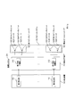
- FIG. 1 is a diagram showing an example of the configuration of an active noise control system.
- the active noise control system is a controller and control that generates a control signal for eliminating noise from a microphone that collects noise (hereinafter referred to as a reference microphone) and a signal output from the reference microphone (hereinafter referred to as a noise signal). Includes a muffling speaker for emitting signal-based sound.
- the active noise control system further includes a microphone (hereinafter referred to as an error microphone) that collects the sound that cannot be completely erased, and feeds back a signal output from the error microphone (hereinafter referred to as an error signal) to the controller.
- the controller may also use an error signal to generate a control signal.
- a speaker unit is used instead of a speaker in order to emit a sound based on a control signal (see FIG. 2).
- a speaker is composed of a speaker unit and a speaker box.
- the speaker unit is a component including a diaphragm that converts an acoustic signal, which is an electric signal, into vibration of air (that is, generates sound waves).
- the speaker box is a component that houses the speaker unit.
- the diaphragm of the speaker unit vibrates, and sound waves are radiated in both directions in which the diaphragm vibrates.
- the sound wave radiated to the outside of the speaker box (that is, toward the front of the speaker unit)
- the sound wave radiated to the inside of the speaker box (that is, toward the back of the speaker unit)
- a negative sound wave is a sound wave having a phase opposite to that of a positive sound wave.
- negative sound waves are also radiated because there is no speaker box.
- the positive sound wave and the negative sound wave are in the opposite phase relationship with each other, the positive sound wave and the negative sound wave cancel each other out, but in the vicinity of the speaker unit, the negative sound wave does not wrap around in time. Positive sound waves remain. If the remaining positive sound waves and noise are in an opposite phase relationship, the positive sound waves cancel each other out with the noise, so that a noise reduction effect can be obtained in the vicinity of the speaker unit.
- the speaker unit is installed near the user's ear without using the speaker box, it is possible to reduce noise in the cabin. Further, since the range in which positive sound waves remain is limited to a relatively narrow range such as the vicinity of the speaker unit, wraparound to the reference microphone can be suppressed, and deterioration of noise reduction performance can also be suppressed.
- the form in which only the speaker unit is installed has the advantage that the installation space can be minimized because the speaker box is not used. Further, in addition to this merit, the form in which only the speaker unit is installed has an advantage that low-frequency sound is produced as compared with the form in which the speaker unit is installed in combination. The reason will be described below. Generally, when the speaker unit is stored in the speaker box, negative sound waves do not go out of the speaker box, but when the speaker unit is stored in the speaker box, it is trapped in the speaker box and has no place to go. The air vibration of the sound wave suppresses the cone of the speaker unit and interferes with the next vibration of the cone. As a result, even if the speaker unit is housed in the speaker box, there is no low-frequency sound.
- a system that reproduces an acoustic signal is called an acoustic system.
- the acoustic system includes a speaker system for emitting an acoustic signal as a sound (hereinafter, this sound is referred to as a sound based on the acoustic signal).
- the speaker system is a device that converts an acoustic signal, which is an analog signal, into sound.
- the acoustic signal to be reproduced by the acoustic system is, for example, an acoustic signal obtained from data recorded on a CD, DVD, or record, data received by the Internet, or a signal received by radio broadcasting or television broadcasting. Is.
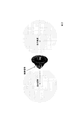
- FIG. 3 is a diagram showing an example of an acoustic system installed in an aircraft seat. The acoustic system of FIG. 3 is arranged so that the speaker system is close to the head of the seated user.
- Such a sound system can be installed on vehicles other than aircraft such as automobiles and trains, chairs used in residential and commercial facilities, and can be installed in a wearable form such as on the shoulder. can.
- a driver unit pair in which two driver units are arranged side by side, which corresponds to the speaker unit pair, may be installed in each of the left and right units of the headphones and earphones.
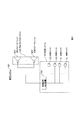
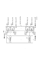
- FIG. 4 is a block diagram showing the configuration of the acoustic system 500.
- the acoustic system 500 includes a control system 510 and a muffling speaker system 520.
- the control system 510 includes K (K is an integer of 1 or more) reference microphones 511, L (L is an integer of 0 or more) error microphones 512, and a control signal generator 514.
- the reference microphone and the error microphone are a microphone that collects noise and a microphone that collects sound that cannot be completely erased, respectively, as described in ⁇ Technical Background>.
- the error microphone is used for updating the filter, and is practically used in many cases.
- the reference microphone is arranged at a position where the noise arrives before the error microphone.
- the error microphone is ideally arranged at the position of the user's ear, it is preferable to arrange it at a position as close to the ear as possible.
- the muffling speaker system 520 includes one muffling speaker unit 5221 which is a speaker unit that emits a sound based on a control signal. The muffling speaker system 520 is installed near the head of the user who uses the seat.
- the direction in which the muffling speaker unit 5221 faces the user is defined as the muffling user direction, and in the muffling speaker unit 5221, the sound emitted from the muffling speaker unit 5221 toward the muffling user is in the direction opposite to the muffling user direction. It is arranged so that the sound is muted at a place other than the place near the head of the user who uses the seat due to the wraparound of the sound emitted to.
- the muffling user direction is the front direction of the muffling speaker unit 5221.
- the direction opposite to the muffling user direction is the back direction of the muffling speaker unit 5221.
- the control system 510 generates and outputs a control signal for eliminating the noise from a signal obtained from the noise near the head of the user who uses the seat of the aircraft (hereinafter referred to as a noise signal). More specifically, the reference microphone 511 collects noise near the head of a user who uses an aircraft seat, and outputs a noise signal obtained by converting the noise into an electric signal. The error microphone 512 collects the unerasable sound at a location extremely close to the user's head, and outputs an error signal obtained by converting the unerasable sound into an electric signal.
- the control signal generation device 514 receives a noise signal and an error signal as inputs, generates a control signal from the noise signal using the error signal, and outputs the control signal.
- the control signal may be a signal having substantially the same amplitude as the noise signal and having an opposite phase.
- the muffling speaker system 520 takes the control signal output by the control system 510 as an input and emits a sound based on the control signal. More specifically, the muffling speaker unit 5221 receives a control signal as an input and emits a sound based on the control signal.
- the sound system 500 of the first embodiment uses only one muffling speaker unit, the range in which noise is reduced is narrow.
- an acoustic system including two or more muffling speaker units will be described so that the muffling speaker units can be installed at positions close to each of the user's ears.
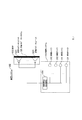
- FIG. 6 is a block diagram showing the configuration of the acoustic system 501.
- the acoustic system 501 includes a control system 510 and a muffling speaker system 520, similarly to the acoustic system 500.
- the sound system 501 differs from the sound system 500 in that the sound deadening speaker system 520 includes M sound deadening speaker units 5221 (M is an integer of 2 or more). The same control signal is input to the M muffling speaker units 5221.
- the M muffling speaker units are referred to as the first muffling speaker unit, ..., the M muffling speaker unit.
- the sound emitted from the unit in the direction of the m mute user is emitted from the m mute speaker unit in the direction opposite to the direction of the m mute user. Arrange so that the sound is muted at the location.
- the m mute user direction is the front direction of the m mute speaker unit 5221.
- the direction opposite to the m mute user direction is the back direction of the m mute speaker unit 5221.
- the range in which noise is reduced is widened by increasing the number of muffling speaker units.
- an acoustic system having a structure in which the range in which noise is reduced by one muffling speaker unit is widened will be described.
- FIG. 7 is a block diagram showing the configuration of the acoustic system 502.
- the acoustic system 502 includes a control system 510 and a muffling speaker system 520, similar to the acoustic system 501.
- the sound path that the sound emitted from the m mute speaker unit 5221 in the direction opposite to the m mute user direction wraps around in the m mute user direction is lengthened.
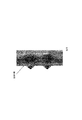
- 5222 is attached (see FIG. 8).
- the member 5222 may be, for example, a member such as a partition plate that prevents sound from wrapping around from the back surface of the speaker unit. This member 5222 is attached in order to prevent interference of sound waves and widen the range in which noise is reduced.
- the m-muffling speaker unit 5221 to which the member 5222 is attached has a wider range of noise reduction than the m-muffling speaker unit 5221 of the second embodiment.
- an acoustic system for reducing the noise around the user who uses the seat of the aircraft has been described.
- These noise reduction acoustic systems can be combined with an acoustic system (reproduction acoustic system) that reproduces sound based on an acoustic signal obtained from a reproduction object only to a user in the vicinity of the speaker system.
- the reproduction target is, for example, sound recorded by a predetermined process such as data recorded on a CD, DVD, or record, data received by the Internet, or a signal received by radio broadcasting or television broadcasting. It is the data or signal from which a signal can be obtained.
- FIG. 9 shows an example of an acoustic system that combines a noise reduction acoustic system and a reproduction acoustic system.
- FIG. 9 is a diagram showing an example of an acoustic system installed in an aircraft seat.
- the speaker system of the reproduction sound system of FIG. 9 is installed in the seat so as to sandwich the head of the seated user, and the speaker unit pair is arranged so as to be close to the left and right ears.
- the muffling speaker system of the noise reduction sound system is installed in the seat so as to be behind the head of the seated user.
- the sound system can be installed on vehicles other than aircraft such as automobiles and trains, reclining chairs, and the like, and can also be installed in a wearable form such as by placing it on a shoulder.
- a driver unit pair in which two driver units are arranged side by side, which corresponds to the speaker unit pair, is installed in each of the left and right units of the headphones and earphones. May be good. Headphones are generally classified into two types, open type (open air type) and closed type (closed type), but if the above technology is applied to the open type, which is particularly concerned about sound leakage, sound leakage will be reduced. There is expected.
- FIG. 10 is a block diagram showing the configuration of the acoustic system 1000.
- the sound system 1000 includes a noise reduction sound system and a reproduction sound system.
- the noise reduction acoustic system can be an acoustic system 500, an acoustic system 501, and an acoustic system 502.
- the reproduction acoustic system may be an acoustic system 100, an acoustic system 102, an acoustic system 104, an acoustic system 106, an acoustic system 108, an acoustic system 200, and an acoustic system 300, which will be described later.
- FIG. 11 is a block diagram showing the configuration of the acoustic system 100.
- the acoustic system 100 includes a reproduction device 110 and a speaker system 120.
- the reproduction device 110 includes N reproduction units 112 (where N is an integer of 1 or more) (that is, the first reproduction unit 112, ..., The Nth reproduction unit 112).
- the speaker system 120 includes N speaker unit pairs 122 (that is, first speaker unit pair 122, ..., Nth speaker unit pair 122).
- the speaker unit pair 122 includes two speaker units (that is, a positive speaker unit 1221 and a negative speaker unit 1221).
- An acoustic signal having a phase opposite to the acoustic signal input to the positive speaker unit 1221 is input to the negative speaker unit 1221.
- the speaker system 120 is installed near the head of the user who uses the seat.
- the 1221 and the negative speaker unit 1221 are a sound emitted from the positive speaker unit 1221 in the direction opposite to the nth user direction and a sound emitted from the negative speaker unit 1221 in the direction opposite to the nth user direction. Is arranged so as to be transmitted in the direction of the nth user by wraparound.
- the n-th user direction is the front direction of the positive speaker unit 1221 and the negative speaker unit 1221 of the n-th speaker unit pair 122.
- the direction opposite to the nth user direction is the back direction of the positive speaker unit 1221 and the negative speaker unit 1221 of the nth speaker unit pair 122.
- the positive speaker unit 1221 and the negative speaker unit 1221 of the nth speaker unit pair 122 are the sound emitted from the positive speaker unit 1221 and the negative speaker unit 1221.
- the sounds emitted from the speakers are arranged so that they are erased from each other so that they cannot be heard by users who use other seats.
- a second n acoustic signal which is a signal, is generated, and a second n-1 acoustic signal and a second n acoustic signal are output.
- the second n-1 acoustic signal and the second n acoustic signal are input to the positive speaker unit 1221 and the negative speaker unit 1221 of the nth speaker unit pair 122, respectively.
- the sound emitted from the positive speaker unit 1221 of the nth speaker unit pair 122 toward the nth user and the sound emitted from the positive speaker unit 1221 of the nth speaker unit pair 122 in the direction opposite to the nth user direction are emitted.
- the sounds are out of phase with each other.
- the resulting sounds are out of phase with each other.
- Sound system 102 >> The sound system 100 has a narrow range in which the emitted sound can be heard, that is, a so-called sweet spot.
- a so-called sweet spot a so-called sweet spot.
- an acoustic system having a structure for widening the sweet spot will be described.
- FIG. 12 is a block diagram showing the configuration of the acoustic system 102.
- the acoustic system 102 includes a reproduction device 110 and a speaker system 120, similarly to the acoustic system 100.
- the acoustic system 102 differs from the acoustic system 100 in that the member 1222 is attached to the speaker unit pair 122.
- n 1, ..., N
- the sound emitted from the positive speaker unit 1221 and the negative speaker unit 1221 of the nth speaker unit pair 122 in the direction opposite to the nth user direction wraps around in the user direction.
- a member 1222 is attached to lengthen the path of (see FIG. 13).
- the member 1222 may be, for example, a member such as a partition plate that prevents sound from wrapping around from the back surface of the speaker unit. This member 1222 does not prevent the sound from wrapping around, but makes the phase difference between the sound wrapping around from the back and the sound from the front side large, that is, to lengthen the path of the sound wrapping around. It is attached to.
- the nth speaker unit pair 122 to which the member 1222 is attached has a wider sweet spot than the nth speaker unit pair 122 of the first embodiment.
- FIG. 14 is a block diagram showing the configuration of the acoustic system 104.
- the acoustic system 104 includes a reproduction device 110 and a speaker system 120, similarly to the acoustic system 100.
- the acoustic system 104 differs from the acoustic system 100 in that a tweeter 1223 is attached to each of the positive speaker unit 1221 and the negative speaker unit 1221 of the speaker unit pair 122.
- the tweeter is a speaker unit for reproducing a high-frequency signal. It is assumed that the tweeter 1223 is attached to the positive speaker unit 1221 and the negative speaker unit 1221 in a form in which sound from the back surface does not leak as if it is housed in the speaker box.
- Sound is emitted from the tweeter 1223 attached to the speaker unit 1221 and the positive speaker unit 1221, and sound based on the second n acoustic signal is emitted from the tweeter 1223 attached to the negative speaker unit 1221 and the negative speaker unit 1221.
- FIG. 15 is a block diagram showing the configuration of the acoustic system 200.
- the acoustic system 200 includes a reproduction device 110, a band division device 210, and a speaker system 120.
- the band dividing device 210 includes N band dividing units 212 (that is, the first band dividing unit 212, ..., The Nth band dividing unit 212).
- the acoustic system 200 differs from the acoustic system 104 in that it includes a band divider 210.
- the band dividing device 210 receives the first acoustic signal, the second acoustic signal, ..., The second N acoustic signal output by the reproduction apparatus 110 as inputs, and is a high frequency signal of the first acoustic signal, which is a low frequency signal and a low frequency signal.
- the first low-frequency signal which is a regional signal
- the second high-frequency signal which is a high-frequency signal of the second acoustic signal
- the second low-frequency signal which is a low-frequency signal
- It outputs the 2N high frequency signal which is a signal and the 2N low frequency signal which is a low frequency signal.
- the nth band dividing unit 212 receives the 2nd n-1 acoustic signal and the 2n acoustic signal as inputs, and is a high-frequency signal of the 2n-1 acoustic signal.
- a 2n-1 high-frequency signal and a low-frequency signal, a 2n-1 low-frequency signal, are generated, and a 2n high-frequency signal and a low-frequency signal, which are high-frequency signals of the 2n acoustic signal, are generated. It generates a 2n low frequency signal and outputs a 2n-1 high frequency signal, a 2n-1 low frequency signal, a 2n high frequency signal, and a 2n low frequency signal.
- the speaker system 120 outputs a first high frequency signal, a first low frequency signal, a second high frequency signal, a second low frequency signal, ..., A second N high frequency signal, and a second N low frequency signal output by the band dividing device 210.
- a sound based on the first high frequency signal, a sound based on the first low frequency signal, a sound based on the second high frequency signal, a sound based on the second low frequency signal, ..., a sound based on the second N high frequency signal Emits a sound based on the 2N low frequency signal.
- the sound based on the 2n-1 low frequency signal and the sound based on the 2n-1 high frequency signal are emitted from the positive speaker unit 1221 and the tweeter 1223 attached to the positive speaker unit 1221, respectively, and the second n
- the sound based on the low frequency signal and the sound based on the 2n high frequency signal are emitted from the negative speaker unit 1221 and the tweeter 1223 attached to the negative speaker unit 1221, respectively.
- Sound system 300 a speaker unit to which the tweeter 1223 is attached is used for the positive speaker unit 1221 and the negative speaker unit 1221.
- a speaker unit pair including two speaker units to which a tweeter is attached instead of using a speaker unit pair including two speaker units to which a tweeter is attached, an acoustic system using a speaker unit pair including two speaker units and one tweeter will be described.
- FIG. 16 is a block diagram showing the configuration of the acoustic system 300.
- the acoustic system 300 includes a reproduction device 110, a band division device 310, and a speaker system 320.
- the band dividing device 310 includes N band dividing units 312 (that is, first band dividing unit 312, ..., Nth band dividing unit 312).
- the speaker system 320 includes N speaker unit pairs 322 (that is, first speaker unit pair 322, ..., Nth speaker unit pair 322).
- the speaker unit pair 322 includes two speaker units (that is, a positive speaker unit 1221 and a negative speaker unit 1221) and a tweeter 3221.
- the sound system 300 differs from the sound system 200 in that it includes the band dividing device 310 and the speaker system 320 instead of the band dividing device 210 and the speaker system 120.
- the tweeter 3221 is preferably housed in a speaker box so that sound from the back does not leak. Further, the speaker system 320 is installed at a position close to the head of the user who uses the seat.
- the 1221 and the negative speaker unit 1221 are a sound emitted from the positive speaker unit 1221 in the direction opposite to the nth user direction and a sound emitted from the negative speaker unit 1221 in the direction opposite to the nth user direction. Is arranged so as to be transmitted in the direction of the nth user by wraparound.
- the n-th user direction is the front direction of the positive speaker unit 1221, the negative speaker unit 1221, and the tweeter 3221 of the n-th speaker unit pair 322.
- the direction opposite to the nth user direction is the back direction of the positive speaker unit 1221, the negative speaker unit 1221, and the tweeter 3221 of the nth speaker unit pair 322.
- the positive speaker unit 1221 and the negative speaker unit 1221 of the nth speaker unit pair 322 are the sound emitted from the positive speaker unit 1221 and the negative speaker unit 1221.
- the sounds emitted from the speakers are arranged so that they are erased from each other so that they cannot be heard by users who use other seats.
- the band dividing device 310 receives the first acoustic signal, the second acoustic signal, ..., The second N acoustic signal output by the reproduction device 110 as inputs, and is a high frequency signal of the first acoustic signal, which is a low frequency signal and a low frequency signal.
- the first low-frequency signal which is a signal in the region
- the second low-frequency signal which is the low-frequency signal of the second acoustic signal
- the second N-1 high-frequency signal which is the high-frequency signal of the second N-1 acoustic signal.
- the speaker system 320 includes a first high-frequency signal, a first low-frequency signal, a second low-frequency signal, ..., A second N-1 high-frequency signal, a second N-1 low-frequency signal, and a second N output output by the band dividing device 310.
- the low frequency signal as the input, the sound based on the 1st high frequency signal, the sound based on the 1st low frequency signal, the sound based on the 2nd low frequency signal, ..., the sound based on the 2N-1 high frequency signal, the 2N- 1 Emits a sound based on a low-frequency signal and 2N a sound based on a low-frequency signal.
- the nth speaker unit pair 322 receives the 2n-1 high frequency signal, the 2n-1 low frequency signal, and the 2n low frequency signal as inputs, and the 2nd n -1
- the sound based on the high frequency signal is emitted from the tweeter 3221
- the sound based on the 2n-1 low frequency signal is emitted from the positive speaker unit 1221
- the sound based on the 2n low frequency signal is emitted from the negative speaker unit. Sound is emitted from 1221.
- the sound system 104 is a system in which high-frequency sound is less likely to leak by using the speaker unit 1221 attached to the tweeter 1223.
- an acoustic system that uses a member having a sound absorbing characteristic to prevent high-frequency sound from leaking will be described.
- FIG. 17 is a block diagram showing the configuration of the acoustic system 106.
- the acoustic system 106 includes a reproduction device 110 and a speaker system 120, similarly to the acoustic system 104.
- the acoustic system 106 is different from the acoustic system 104 in that the speaker unit 1221 to which the tweeter 1223 is not attached is used instead of the speaker unit 1221 to which the tweeter 1223 is attached, and the member 1224 is attached to the speaker unit pair 122. different.
- n 1, ..., N
- a member 1224 for absorbing the sound emitted from the positive speaker unit 1221 and the negative speaker unit 1221 of the nth speaker unit pair 122 in the direction opposite to the nth user direction is attached to the nth speaker unit pair 122. (See FIG. 18).
- the member 1224 may be any member as long as it can prevent the high frequency sound from being radiated from the back surface. Instead of installing the member 1224 only on the back surface of the speaker unit pair 122, the member 1224 may be installed so as to surround other than the front surface of the speaker unit pair 122.
- the sound system 106 is a system in which high-frequency sound is less likely to leak by using the speaker unit 1221 to which the member 1224 is attached.
- the sound system 106 instead of using a speaker unit pair to which a sound absorbing material is attached, by storing each of the speaker units of the speaker unit pair in a speaker box having a hole, an acoustic system in which high-frequency sound is less likely to leak will be described. ..
- FIG. 19 is a block diagram showing the configuration of the acoustic system 108.
- the acoustic system 108 includes a reproduction device 110 and a speaker system 120, similarly to the acoustic system 106.
- the acoustic system 108 differs from the acoustic system 106 in that it includes the speaker unit pair 122 including the speaker unit 1221 housed in the speaker box 1225 instead of the speaker unit pair 122 to which the member 1224 is attached.
- n 1, ..., N
- the positive speaker unit 1221 and the negative speaker unit 1221 of the nth speaker unit pair 122 are housed in the speaker box 1225, respectively.
- the speaker box 1225 has a large number of holes.
- the embodiment of the present invention it is possible to reduce the noise heard when seated in an aircraft seat. At the same time, it is possible to reproduce sound that can be heard only in a very limited narrow range such as the vicinity of the speaker system.
Landscapes
- Physics & Mathematics (AREA)
- Engineering & Computer Science (AREA)
- Acoustics & Sound (AREA)
- Multimedia (AREA)
- Signal Processing (AREA)
- Health & Medical Sciences (AREA)
- Audiology, Speech & Language Pathology (AREA)
- General Health & Medical Sciences (AREA)
- Soundproofing, Sound Blocking, And Sound Damping (AREA)
Priority Applications (4)
| Application Number | Priority Date | Filing Date | Title |
|---|---|---|---|
| US17/914,378 US12190856B2 (en) | 2020-03-30 | 2020-03-30 | Sound system |
| PCT/JP2020/014471 WO2021199115A1 (ja) | 2020-03-30 | 2020-03-30 | 音響システム |
| JP2022512512A JP7384272B2 (ja) | 2020-03-30 | 2020-03-30 | 音響システム |
| US18/956,150 US20250087200A1 (en) | 2020-03-30 | 2024-11-22 | Sound system |
Applications Claiming Priority (1)
| Application Number | Priority Date | Filing Date | Title |
|---|---|---|---|
| PCT/JP2020/014471 WO2021199115A1 (ja) | 2020-03-30 | 2020-03-30 | 音響システム |
Related Child Applications (2)
| Application Number | Title | Priority Date | Filing Date |
|---|---|---|---|
| US17/914,378 A-371-Of-International US12190856B2 (en) | 2020-03-30 | 2020-03-30 | Sound system |
| US18/956,150 Continuation US20250087200A1 (en) | 2020-03-30 | 2024-11-22 | Sound system |
Publications (1)
| Publication Number | Publication Date |
|---|---|
| WO2021199115A1 true WO2021199115A1 (ja) | 2021-10-07 |
Family
ID=77929783
Family Applications (1)
| Application Number | Title | Priority Date | Filing Date |
|---|---|---|---|
| PCT/JP2020/014471 Ceased WO2021199115A1 (ja) | 2020-03-30 | 2020-03-30 | 音響システム |
Country Status (3)
| Country | Link |
|---|---|
| US (2) | US12190856B2 (https=) |
| JP (1) | JP7384272B2 (https=) |
| WO (1) | WO2021199115A1 (https=) |
Families Citing this family (2)
| Publication number | Priority date | Publication date | Assignee | Title |
|---|---|---|---|---|
| US20250211899A1 (en) * | 2022-03-28 | 2025-06-26 | Nippon Telegraph And Telephone Corporation | Sound system |
| US12490003B2 (en) * | 2022-05-11 | 2025-12-02 | Panasonic Intellectual Property Managment Co., Ltd. | Sound reproduction device |
Citations (3)
| Publication number | Priority date | Publication date | Assignee | Title |
|---|---|---|---|---|
| JP2008271067A (ja) * | 2007-04-19 | 2008-11-06 | Sony Corp | ノイズ低減装置および音響再生装置 |
| JP2009088784A (ja) * | 2007-09-28 | 2009-04-23 | Sanyo Electric Co Ltd | 音声再生装置 |
| JP2019536107A (ja) * | 2016-11-23 | 2019-12-12 | ボーズ・コーポレーションBosecorporation | 遮音用の音響システム及び方法 |
Family Cites Families (3)
| Publication number | Priority date | Publication date | Assignee | Title |
|---|---|---|---|---|
| US7440578B2 (en) * | 2001-05-28 | 2008-10-21 | Mitsubishi Denki Kabushiki Kaisha | Vehicle-mounted three dimensional sound field reproducing silencing unit |
| EP2975863A1 (en) * | 2014-07-15 | 2016-01-20 | Phitek Systems Limited | Noise cancellation system |
| US10293728B2 (en) * | 2016-08-24 | 2019-05-21 | Bose Corporation | Acoustic transducer assembly disposed in vehicle seat |
-
2020
- 2020-03-30 US US17/914,378 patent/US12190856B2/en active Active
- 2020-03-30 JP JP2022512512A patent/JP7384272B2/ja active Active
- 2020-03-30 WO PCT/JP2020/014471 patent/WO2021199115A1/ja not_active Ceased
-
2024
- 2024-11-22 US US18/956,150 patent/US20250087200A1/en active Pending
Patent Citations (3)
| Publication number | Priority date | Publication date | Assignee | Title |
|---|---|---|---|---|
| JP2008271067A (ja) * | 2007-04-19 | 2008-11-06 | Sony Corp | ノイズ低減装置および音響再生装置 |
| JP2009088784A (ja) * | 2007-09-28 | 2009-04-23 | Sanyo Electric Co Ltd | 音声再生装置 |
| JP2019536107A (ja) * | 2016-11-23 | 2019-12-12 | ボーズ・コーポレーションBosecorporation | 遮音用の音響システム及び方法 |
Also Published As
| Publication number | Publication date |
|---|---|
| US20250087200A1 (en) | 2025-03-13 |
| US20230139520A1 (en) | 2023-05-04 |
| JPWO2021199115A1 (https=) | 2021-10-07 |
| JP7384272B2 (ja) | 2023-11-21 |
| US12190856B2 (en) | 2025-01-07 |
Similar Documents
| Publication | Publication Date | Title |
|---|---|---|
| JP7151840B2 (ja) | 音響システム | |
| US20250266029A1 (en) | Sound system | |
| US20250087200A1 (en) | Sound system | |
| JP7622812B2 (ja) | 音響システム | |
| JP7845519B2 (ja) | 音響システム | |
| JP7605220B2 (ja) | 音響システム | |
| JP7622750B2 (ja) | スピーカシステム | |
| WO2023187900A1 (ja) | 音響システム | |
| JP7364044B2 (ja) | スピーカシステム | |
| US20240137694A1 (en) | Sound system |
Legal Events
| Date | Code | Title | Description |
|---|---|---|---|
| 121 | Ep: the epo has been informed by wipo that ep was designated in this application |
Ref document number: 20929239 Country of ref document: EP Kind code of ref document: A1 |
|
| ENP | Entry into the national phase |
Ref document number: 2022512512 Country of ref document: JP Kind code of ref document: A |
|
| NENP | Non-entry into the national phase |
Ref country code: DE |
|
| 122 | Ep: pct application non-entry in european phase |
Ref document number: 20929239 Country of ref document: EP Kind code of ref document: A1 |