US12190856B2 - Sound system - Google Patents
Sound system Download PDFInfo
- Publication number
- US12190856B2 US12190856B2 US17/914,378 US202017914378A US12190856B2 US 12190856 B2 US12190856 B2 US 12190856B2 US 202017914378 A US202017914378 A US 202017914378A US 12190856 B2 US12190856 B2 US 12190856B2
- Authority
- US
- United States
- Prior art keywords
- sound
- noise
- speaker unit
- cancellation
- signal
- Prior art date
- Legal status (The legal status is an assumption and is not a legal conclusion. Google has not performed a legal analysis and makes no representation as to the accuracy of the status listed.)
- Active, expires
Links
Images




Classifications
-
- G—PHYSICS
- G10—MUSICAL INSTRUMENTS; ACOUSTICS
- G10K—SOUND-PRODUCING DEVICES; METHODS OR DEVICES FOR PROTECTING AGAINST, OR FOR DAMPING, NOISE OR OTHER ACOUSTIC WAVES IN GENERAL; ACOUSTICS NOT OTHERWISE PROVIDED FOR
- G10K11/00—Methods or devices for transmitting, conducting or directing sound in general; Methods or devices for protecting against, or for damping, noise or other acoustic waves in general
- G10K11/16—Methods or devices for protecting against, or for damping, noise or other acoustic waves in general
- G10K11/175—Methods or devices for protecting against, or for damping, noise or other acoustic waves in general using interference effects; Masking sound
- G10K11/178—Methods or devices for protecting against, or for damping, noise or other acoustic waves in general using interference effects; Masking sound by electro-acoustically regenerating the original acoustic waves in anti-phase
- G10K11/1787—General system configurations
- G10K11/17879—General system configurations using both a reference signal and an error signal
- G10K11/17881—General system configurations using both a reference signal and an error signal the reference signal being an acoustic signal, e.g. recorded with a microphone
-
- H—ELECTRICITY
- H04—ELECTRIC COMMUNICATION TECHNIQUE
- H04R—LOUDSPEAKERS, MICROPHONES, GRAMOPHONE PICK-UPS OR LIKE ACOUSTIC ELECTROMECHANICAL TRANSDUCERS; ELECTRIC HEARING AIDS; PUBLIC ADDRESS SYSTEMS
- H04R5/00—Stereophonic arrangements
- H04R5/02—Spatial or constructional arrangements of loudspeakers
- H04R5/023—Spatial or constructional arrangements of loudspeakers in a chair, pillow
-
- G—PHYSICS
- G10—MUSICAL INSTRUMENTS; ACOUSTICS
- G10K—SOUND-PRODUCING DEVICES; METHODS OR DEVICES FOR PROTECTING AGAINST, OR FOR DAMPING, NOISE OR OTHER ACOUSTIC WAVES IN GENERAL; ACOUSTICS NOT OTHERWISE PROVIDED FOR
- G10K11/00—Methods or devices for transmitting, conducting or directing sound in general; Methods or devices for protecting against, or for damping, noise or other acoustic waves in general
- G10K11/16—Methods or devices for protecting against, or for damping, noise or other acoustic waves in general
- G10K11/175—Methods or devices for protecting against, or for damping, noise or other acoustic waves in general using interference effects; Masking sound
- G10K11/178—Methods or devices for protecting against, or for damping, noise or other acoustic waves in general using interference effects; Masking sound by electro-acoustically regenerating the original acoustic waves in anti-phase
- G10K11/1785—Methods, e.g. algorithms; Devices
- G10K11/17857—Geometric disposition, e.g. placement of microphones
-
- G—PHYSICS
- G10—MUSICAL INSTRUMENTS; ACOUSTICS
- G10K—SOUND-PRODUCING DEVICES; METHODS OR DEVICES FOR PROTECTING AGAINST, OR FOR DAMPING, NOISE OR OTHER ACOUSTIC WAVES IN GENERAL; ACOUSTICS NOT OTHERWISE PROVIDED FOR
- G10K11/00—Methods or devices for transmitting, conducting or directing sound in general; Methods or devices for protecting against, or for damping, noise or other acoustic waves in general
- G10K11/16—Methods or devices for protecting against, or for damping, noise or other acoustic waves in general
- G10K11/175—Methods or devices for protecting against, or for damping, noise or other acoustic waves in general using interference effects; Masking sound
- G10K11/178—Methods or devices for protecting against, or for damping, noise or other acoustic waves in general using interference effects; Masking sound by electro-acoustically regenerating the original acoustic waves in anti-phase
- G10K11/1787—General system configurations
- G10K11/17879—General system configurations using both a reference signal and an error signal
-
- G—PHYSICS
- G10—MUSICAL INSTRUMENTS; ACOUSTICS
- G10K—SOUND-PRODUCING DEVICES; METHODS OR DEVICES FOR PROTECTING AGAINST, OR FOR DAMPING, NOISE OR OTHER ACOUSTIC WAVES IN GENERAL; ACOUSTICS NOT OTHERWISE PROVIDED FOR
- G10K11/00—Methods or devices for transmitting, conducting or directing sound in general; Methods or devices for protecting against, or for damping, noise or other acoustic waves in general
- G10K11/16—Methods or devices for protecting against, or for damping, noise or other acoustic waves in general
- G10K11/175—Methods or devices for protecting against, or for damping, noise or other acoustic waves in general using interference effects; Masking sound
- G10K11/178—Methods or devices for protecting against, or for damping, noise or other acoustic waves in general using interference effects; Masking sound by electro-acoustically regenerating the original acoustic waves in anti-phase
- G10K11/1787—General system configurations
- G10K11/17885—General system configurations additionally using a desired external signal, e.g. pass-through audio such as music or speech
-
- H—ELECTRICITY
- H04—ELECTRIC COMMUNICATION TECHNIQUE
- H04R—LOUDSPEAKERS, MICROPHONES, GRAMOPHONE PICK-UPS OR LIKE ACOUSTIC ELECTROMECHANICAL TRANSDUCERS; ELECTRIC HEARING AIDS; PUBLIC ADDRESS SYSTEMS
- H04R1/00—Details of transducers, loudspeakers or microphones
- H04R1/02—Casings; Cabinets ; Supports therefor; Mountings therein
- H04R1/025—Arrangements for fixing loudspeaker transducers, e.g. in a box, furniture
-
- H—ELECTRICITY
- H04—ELECTRIC COMMUNICATION TECHNIQUE
- H04R—LOUDSPEAKERS, MICROPHONES, GRAMOPHONE PICK-UPS OR LIKE ACOUSTIC ELECTROMECHANICAL TRANSDUCERS; ELECTRIC HEARING AIDS; PUBLIC ADDRESS SYSTEMS
- H04R1/00—Details of transducers, loudspeakers or microphones
- H04R1/10—Earpieces; Attachments therefor ; Earphones; Monophonic headphones
- H04R1/1083—Reduction of ambient noise
-
- G—PHYSICS
- G10—MUSICAL INSTRUMENTS; ACOUSTICS
- G10K—SOUND-PRODUCING DEVICES; METHODS OR DEVICES FOR PROTECTING AGAINST, OR FOR DAMPING, NOISE OR OTHER ACOUSTIC WAVES IN GENERAL; ACOUSTICS NOT OTHERWISE PROVIDED FOR
- G10K2210/00—Details of active noise control [ANC] covered by G10K11/178 but not provided for in any of its subgroups
- G10K2210/10—Applications
- G10K2210/128—Vehicles
- G10K2210/1281—Aircraft, e.g. spacecraft, airplane or helicopter
-
- G—PHYSICS
- G10—MUSICAL INSTRUMENTS; ACOUSTICS
- G10K—SOUND-PRODUCING DEVICES; METHODS OR DEVICES FOR PROTECTING AGAINST, OR FOR DAMPING, NOISE OR OTHER ACOUSTIC WAVES IN GENERAL; ACOUSTICS NOT OTHERWISE PROVIDED FOR
- G10K2210/00—Details of active noise control [ANC] covered by G10K11/178 but not provided for in any of its subgroups
- G10K2210/30—Means
- G10K2210/301—Computational
- G10K2210/3046—Multiple acoustic inputs, multiple acoustic outputs
-
- G—PHYSICS
- G10—MUSICAL INSTRUMENTS; ACOUSTICS
- G10K—SOUND-PRODUCING DEVICES; METHODS OR DEVICES FOR PROTECTING AGAINST, OR FOR DAMPING, NOISE OR OTHER ACOUSTIC WAVES IN GENERAL; ACOUSTICS NOT OTHERWISE PROVIDED FOR
- G10K2210/00—Details of active noise control [ANC] covered by G10K11/178 but not provided for in any of its subgroups
- G10K2210/30—Means
- G10K2210/321—Physical
- G10K2210/3219—Geometry of the configuration
-
- G—PHYSICS
- G10—MUSICAL INSTRUMENTS; ACOUSTICS
- G10K—SOUND-PRODUCING DEVICES; METHODS OR DEVICES FOR PROTECTING AGAINST, OR FOR DAMPING, NOISE OR OTHER ACOUSTIC WAVES IN GENERAL; ACOUSTICS NOT OTHERWISE PROVIDED FOR
- G10K2210/00—Details of active noise control [ANC] covered by G10K11/178 but not provided for in any of its subgroups
- G10K2210/30—Means
- G10K2210/321—Physical
- G10K2210/3221—Headrests, seats or the like, for personal ANC systems
-
- G—PHYSICS
- G10—MUSICAL INSTRUMENTS; ACOUSTICS
- G10K—SOUND-PRODUCING DEVICES; METHODS OR DEVICES FOR PROTECTING AGAINST, OR FOR DAMPING, NOISE OR OTHER ACOUSTIC WAVES IN GENERAL; ACOUSTICS NOT OTHERWISE PROVIDED FOR
- G10K2210/00—Details of active noise control [ANC] covered by G10K11/178 but not provided for in any of its subgroups
- G10K2210/30—Means
- G10K2210/321—Physical
- G10K2210/3229—Transducers
-
- H—ELECTRICITY
- H04—ELECTRIC COMMUNICATION TECHNIQUE
- H04R—LOUDSPEAKERS, MICROPHONES, GRAMOPHONE PICK-UPS OR LIKE ACOUSTIC ELECTROMECHANICAL TRANSDUCERS; ELECTRIC HEARING AIDS; PUBLIC ADDRESS SYSTEMS
- H04R2460/00—Details of hearing devices, i.e. of ear- or headphones covered by H04R1/10 or H04R5/033 but not provided for in any of their subgroups, or of hearing aids covered by H04R25/00 but not provided for in any of its subgroups
- H04R2460/01—Hearing devices using active noise cancellation
-
- H—ELECTRICITY
- H04—ELECTRIC COMMUNICATION TECHNIQUE
- H04R—LOUDSPEAKERS, MICROPHONES, GRAMOPHONE PICK-UPS OR LIKE ACOUSTIC ELECTROMECHANICAL TRANSDUCERS; ELECTRIC HEARING AIDS; PUBLIC ADDRESS SYSTEMS
- H04R2499/00—Aspects covered by H04R or H04S not otherwise provided for in their subgroups
- H04R2499/10—General applications
- H04R2499/13—Acoustic transducers and sound field adaptation in vehicles
Definitions
- the present invention relates to a technology for reducing noise in an aircraft.
- Non-Patent Literature 1 When users are annoyed with noise while viewing a movie, listening to music, or the like in an aircraft, the users have used earphones or headphones including a noise canceling function (see Non-Patent Literature 1).
- wearing earphones or headphones makes users uncomfortable. Moreover, some users do not like wearing such devices because hairstyles become untidy. There are also some users who dislike pressure on ears caused by wearing the devices. Further, a long period of wearing earphones or headphones may make users tired of hearing in some cases.
- an object of the present invention is to provide a technology that reduces noise heard when a user sits in a seat of an aircraft, without using earphones or headphones.
- An aspect of the present invention includes: a control system that generates a control signal for canceling noise in a place close to a head of a user using a seat of an aircraft, from a signal of the noise (hereinafter, referred to as the noise signal); and a noise-cancellation speaker system including M speaker units that emit sound based on the control signal (hereinafter, referred to as the noise-cancellation speaker units), M being an integer equal to or larger than one, the noise-cancellation speaker system being installed at the place close to the head of the user using the seat, wherein assuming that the M noise-cancellation speaker units are a first noise-cancellation speaker unit, . . .
- FIG. 1 shows an example of a configuration of an active noise control system.
- FIG. 2 is a view for describing directivity of sound emitted from a speaker unit.
- FIG. 3 shows an example of a sound system installed in a seat of an aircraft.
- FIG. 4 is a block diagram showing an example of a configuration of a sound system 500 .
- FIG. 5 shows an example of disposition of reference microphones and error microphones.
- FIG. 6 is a block diagram showing an example of a configuration of a sound system 501 .
- FIG. 7 is a block diagram showing an example of a configuration of a sound system 502 .
- FIG. 8 shows an example of a configuration of a noise-cancellation speaker system 520 to which a member 5222 is attached.
- FIG. 9 shows an example of a sound system installed in a seat of an aircraft.
- FIG. 10 is a block diagram showing an example of a configuration of a sound system 1000 .
- FIG. 11 is a block diagram showing an example of a configuration of a sound system 100 .
- FIG. 12 is a block diagram showing an example of a configuration of a sound system 102 .
- FIG. 13 shows an example of a configuration of a speaker unit pair 122 to which a member 1222 is attached.
- FIG. 14 is a block diagram showing an example of a configuration of a sound system 104 .
- FIG. 15 is a block diagram showing an example of a configuration of a sound system 200 .
- FIG. 16 is a block diagram showing an example of a configuration of a sound system 300 .
- FIG. 17 is a block diagram showing an example of a configuration of a sound system 106 .
- FIG. 18 shows an example of a configuration of the speaker unit pair 122 to which a member 1224 is attached.
- FIG. 19 is a block diagram showing an example of a configuration of a sound system 108 .
- Active noise control which is one of noise reduction technologies, is used to reduce noise heard when a user sits in a seat of an aircraft (see Reference Non-Patent Literatures 1, 2).
- FIG. 1 shows an example of a configuration of an active noise control system.
- the active noise control system includes a microphone that picks up noise (hereinafter, referred to as reference microphone), a controller that generates, from a signal outputted from the reference microphone (hereinafter, referred to as noise signal), a control signal for canceling the noise, and a noise-cancellation speaker for emitting sound based on the control signal.
- the active noise control system may further include a microphone that picks up sound that cannot be canceled out (hereinafter, referred to as error microphone), and may be configured such that a signal outputted from the error microphone (hereinafter, referred to as error signal) is fed back to the controller and the controller generates a control signal by using also the error signal.
- error microphone a microphone that picks up sound that cannot be canceled out
- the invention of the present application uses a speaker unit instead of using a speaker, to emit sound based on a control signal (see FIG. 2 ).
- a speaker includes a speaker unit and a speaker box.
- the speaker unit is a component including a diaphragm that converts a sound signal, which is an electrical signal, into aerial vibration (that is, generates sound waves).
- the speaker box is a component that houses the speaker unit.
- a sound wave emitted to the outside of the speaker box (that is, in a direction toward the front of the speaker unit)
- a sound wave emitted to the inside of the speaker box (that is, in a direction toward the rear of the speaker unit)
- the negative sound wave is a sound wave with opposite phase to phase of the positive sound wave.
- the speaker unit is installed in a form without using the speaker box at a place close to an ear of a user, noise reduction in an aircraft can be achieved. Moreover, since an area where the positive sound waves remain is limited to a relatively small area such as the vicinity of the speaker unit, bending around of sound to the reference microphone is restrained, and degradation in noise reduction performance can also be restrained.
- the form in which only the speaker unit is installed has a merit that an installation space can be minimized because no speaker box is used. Moreover, in addition to such a merit, the form in which only the speaker unit is installed also has a merit that lower-frequency sound can be reproduced than in a form in which the speaker unit is installed in combination with the speaker box. The reason will be described below.
- negative sound waves do not go out of the speaker box.
- a system that reproduces a sound signal is referred to as a sound system.
- the sound system includes a speaker system in order to emit the sound signal as sound (hereinafter, such sound will be referred to as sound based on a sound signal).
- the speaker system is a device that converts the sound signal, which is an analog signal, into sound.
- the sound signal to be reproduced by the sound system is a sound signal obtained from, for example, data recorded on a CD, a DVD, or a record, data received over the Internet, or a signal received through radio broadcasting or television broadcasting.
- FIG. 3 shows an example of the sound system installed in a seat of an aircraft. The sound system in FIG. 3 is disposed such that a speaker system is positioned in the vicinity of a head of a user sitting in the seat.
- a sound system can also be installed on vehicles other than aircrafts, such as automobiles and trains, and in chairs used in houses and commercial facilities, and can also be installed in a wearable form to be put on a shoulder or the like.
- a driver unit pair including two driver units arranged side by side, which corresponds to a pair of the above-mentioned speaker units, may be installed in each of right and left units of headphones or earphones.
- FIG. 4 is a block diagram showing a configuration of the sound system 500 .
- the sound system 500 includes a control system 510 and a noise-cancellation speaker system 520 .
- the control system 510 includes K (K is an integer equal to or larger than one) reference microphones 511 , L (L is an integer equal to or larger than zero) error microphones 512 , and a control signal generation apparatus 514 .
- the reference microphones and the error microphones are, as described in the ⁇ Technical background> section, microphones that pick up noise, and microphones that pick up sound that cannot be canceled out, respectively.
- the noise-cancellation speaker system 520 includes one noise-cancellation speaker unit 5221 that is a speaker unit emitting sound based on a control signal. The noise-cancellation speaker system 520 is installed at a place close to a head of the user using the seat.
- noise-cancellation user direction a direction in which the noise-cancellation speaker unit 5221 faces the user
- the noise-cancellation speaker unit 5221 is disposed such that sound emitted from the noise-cancellation speaker unit 5221 in the noise-cancellation user direction is canceled in places other than the place close to the head of the user using the seat, due to bending around of sound emitted from the noise-cancellation speaker unit 5221 in an opposite direction to the noise-cancellation user direction.
- the noise-cancellation user direction is a direction toward the front of the noise-cancellation speaker unit 5221 .
- the opposite direction to the noise-cancellation user direction is a direction toward the rear of the noise-cancellation speaker unit 5221 .
- the control system 510 generates a control signal for canceling noise in the place close to the head of the user using the seat of the aircraft, from a signal obtained from the noise (hereinafter, referred to as noise signal), and outputs the control signal. More specifically, the reference microphones 511 pick up noise in the place close to the head of the user using the seat of the aircraft, and outputs a noise signal that is obtained by converting the noise into an electrical signal. The error microphones 512 pick up sound that cannot be canceled out in a place extremely close to the head of the user, and outputs an error signal that is obtained by converting the sound that cannot be canceled out into an electrical signal.
- the control signal generation apparatus 514 receives the noise signal and the error signal as inputs, generates a control signal from the noise signal by using the error signal, and outputs the control signal.
- the control signal may be a signal with almost the same amplitude as and opposite phase to the noise signal.
- the noise-cancellation speaker system 520 receives the control signal outputted by the control system 510 as an input, and emits sound based on the control signal. More specifically, the noise-cancellation speaker unit 5221 receives the control signal as an input, and emits sound based on the control signal.
- the sound system 500 in the first embodiment uses only one noise-cancellation speaker unit, and an area where noise is reduced is therefore small.
- a description will be given of a sound system including two or more noise-cancellation speaker units in order that the noise-cancellation speaker units can be installed at places respectively close to both ears of a user.
- FIG. 6 is a block diagram showing a configuration of the sound system 501 .
- the sound system 501 includes a control system 510 and a noise-cancellation speaker system 520 , similarly to the sound system 500 .
- the sound system 501 is different from the sound system 500 in a point that the noise-cancellation speaker system 520 includes M (M is an integer equal to or larger than two) noise-cancellation speaker units 5221 .
- the M noise-cancellation speaker units 5221 receive the same control signal, as respective inputs.
- the M noise-cancellation speaker units will be referred to as first noise-cancellation speaker unit, . . . , and M-th noise-cancellation speaker unit.
- M is disposed such that sound emitted from the m-th noise-cancellation speaker unit in the m-th noise-cancellation user direction is canceled in places other than a place closed to a head of the user using the seat, due to bending around of sound emitted from the m-th noise-cancellation speaker unit in an opposite direction to the m-th noise-cancellation user direction.
- the m-th noise-cancellation user direction is a direction toward the front of the m-th noise-cancellation speaker unit 5221 .
- the opposite direction to the m-th noise-cancellation user direction is a direction toward the rear of the m-th noise-cancellation speaker unit 5221 .
- the area where noise is reduced is enlarged by increasing the number of noise-cancellation speaker units.
- a description will be given of a sound system having a structure that enlarges the area where noise is reduced, with one noise-cancellation speaker unit.
- FIG. 7 is a block diagram showing a configuration of the sound system 502 .
- the sound system 502 includes a control system 510 and a noise-cancellation speaker system 520 , similarly to the sound system 501 .
- the member 5222 is attached to the m-th noise-cancellation speaker unit 5221 (see FIG. 8 ).
- the member 5222 is for lengthening a path of sound bending around in the m-th noise-cancellation user direction, of sound emitted from the m-th noise-cancellation speaker unit 5221 in the opposite direction to the m-th noise-cancellation user direction.
- the member 5222 may be a member such as a partition plate that prevents sound from bending around from the rear of the speaker unit.
- the member 5222 is attached in order to prevent interference of sound waves and to enlarge the area where noise is reduced.
- the m-th noise-cancellation speaker unit 5221 to which the member 5222 is attached reduces noise in a larger area than the m-th noise-cancellation speaker unit 5221 in the second embodiment.
- the noise reduction sound systems can be combined with a sound system (reproduction sound system) that reproduces sound based on a sound signal obtained from a subject to be reproduced such that the sound can be heard only by a user in the vicinity of a speaker system.
- the subject to be reproduced is, for example, data or a signal from which the sound signal can be obtained through predetermined processing, such as data recorded on a CD, a DVD, or a record, data received over the Internet, or a signal received through radio broadcasting or television broadcasting.
- FIG. 9 shows an example of the sound system installed in a seat of an aircraft.
- a speaker system of the reproduction sound system in FIG. 9 is installed in the seat so as to interpose a head of a user sitting in the seat in between, and is disposed such that speaker unit pairs are positioned in the vicinities of the right and left ears.
- a noise-cancellation speaker system of the noise reduction sound system is installed in the seat so as to be positioned at the back of the head of the user sitting in the seat.
- the sound system can also be installed on vehicles other than aircrafts, such as automobiles and trains, and in reclining chairs and the like, and can also be installed in a wearable form to be put on a shoulder or the like.
- the reproduction sound system may have a configuration in which a driver unit pair including two driver units arranged side by side, which corresponds to a pair of the above-described speaker units, is installed in each of right and left units of headphones or earphones.
- the headphones are broadly divided into open-air type and closed type in general, and when the above-described technique is applied particularly to the open-air type, sound leakage from which is a concern, a reduction in leaking sound can be expected.
- FIG. 10 is a block diagram showing a configuration of the sound system 1000 .
- the sound system 1000 includes a noise reduction sound system and a reproduction sound system.
- the noise reduction sound system can be the sound system 500 , the sound system 501 , or the sound system 502 .
- the reproduction sound system can be a sound system 100 , a sound system 102 , a sound system 104 , a sound system 106 , a sound system 108 , a sound system 200 , or a sound system 300 , which will be described below.
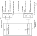
- FIG. 11 is a block diagram showing a configuration of the sound system 100 .
- the sound system 100 includes a reproduction apparatus 110 and a speaker system 120 .
- the reproduction apparatus 110 includes N (N is an integer equal to or larger than one) reproduction units 112 (that is, a first reproduction unit 112 , . . . , an N-th reproduction unit 112 ).
- the speaker system 120 includes N speaker unit pairs 122 (that is, a first speaker unit pair 122 , . . . , an N-th speaker unit pair 122 ).
- Each speaker unit pair 122 includes two speaker units (that is, a positive speaker unit 1221 and a negative speaker unit 1221 ).
- the negative speaker unit 1221 receives, as an input, a sound signal with opposite phase to that of a sound signal inputted into the positive speaker unit 1221 .
- the speaker system 120 is installed at a place close to a head of a user using the seat.
- n-th user direction a direction in which an n-th speaker unit pair 122 faces the user
- n-th user direction a direction in which an n-th speaker unit pair 122 faces the user
- the positive speaker unit 1221 and the negative speaker unit 1221 of the n-th speaker unit pair 122 are disposed such that sound emitted from the positive speaker unit 1221 in an opposite direction to the n-th user direction and sound emitted from the negative speaker unit 1221 in the opposite direction to the n-th user direction propagate in the n-th user direction due to bending around of the sound.
- the n-th user direction is a direction toward the front of the positive speaker unit 1221 and the negative speaker unit 1221 of the n-th speaker unit pair 122 .
- the opposite direction to the n-th user direction is a direction toward the rear of the positive speaker unit 1221 and the negative speaker unit 1221 of the n-th speaker unit pair 122 .
- the positive speaker unit 1221 and the negative speaker unit 1221 of the n-th speaker unit pair 122 are disposed in a positional relationship in which sound emitted from the positive speaker unit 1221 and sound emitted from the negative speaker unit 1221 cancel each other out so that the sound cannot be heard by users using other seats.
- N receives a (2n ⁇ 1)-th sound signal as an input, generates, from the (2n ⁇ 1)-th sound signal, a 2n-th sound signal that is a sound signal with opposite phase to that of the (2n ⁇ 1)-th sound signal, and outputs the (2n ⁇ 1)-th sound signal and the 2n-th sound signal.
- the (2n ⁇ 1)-th sound signal and the 2n-th sound signal are inputted into the positive speaker unit 1221 and the negative speaker unit 1221 of the n-th speaker unit pair 122 , respectively.
- the (2n ⁇ 1)-th sound signal and the 2n-th sound signal are in an antiphase relationship with each other, sound is heard only in the vicinity of the seat in which the speaker system 120 is installed.
- N 2n2
- the first sound signal and the third sound signal are sound signals from a right channel and a left channel of a sound source, respectively, stereo sound can be heard only in the vicinity of the seat in which the speaker system 120 is installed.
- the sound emitted from the positive speaker unit 1221 of the n-th speaker unit pair 122 in the n-th user direction and the sound emitted from the positive speaker unit 1221 of the n-th speaker unit pair 122 in the opposite direction to the n-th user direction are in an antiphase relationship.
- the sound emitted from the negative speaker unit 1221 of the n-th speaker unit pair 122 in the n-th user direction and the sound emitted from the negative speaker unit 1221 of the n-th speaker unit pair 122 in the opposite direction to the n-th user direction are in an antiphase relationship.
- the sound system 100 has a small so-called sweet spot, which is an area where emitted sound is heard.
- sweet spot is an area where emitted sound is heard.
- a description will be given of a sound system having a structure that enlarges the sweet spot.
- FIG. 12 is a block diagram showing a configuration of the sound system 102 .
- the sound system 102 includes a reproduction apparatus 110 and a speaker system 120 , similarly to the sound system 100 .
- the sound system 102 is different from the sound system 100 in a point that a member 1222 is attached to each speaker unit pair 122 .
- the member 1222 is attached to the n-th speaker unit pair 122 (see FIG. 13 ).
- the member 1222 is for lengthening a path of sound bending around in the n-th user direction, of sound emitted from a positive speaker unit 1221 and a negative speaker unit 1221 of the n-th speaker unit pair 122 in an opposite direction to the n-th user direction.
- the member 1222 may be a member such as a partition plate that prevents sound from bending around from the rear of the speaker units.
- the member 1222 is attached, not to prevent bending around of sound, but to make a phase difference larger between the sound bending around from the rear and sound from the front, that is, to lengthen the path of the sound bending around.
- the n-th speaker unit pair 122 to which the member 1222 is attached has a larger sweet spot than the n-th speaker unit pair 122 in the form 1.
- FIG. 14 is a block diagram showing a configuration of the sound system 104 .
- the sound system 104 includes a reproduction apparatus 110 and a speaker system 120 , similarly to the sound system 100 .
- the sound system 104 is different from the sound system 100 in a point that a tweeter 1223 is added to each of a positive speaker unit 1221 and a negative speaker unit 1221 of each speaker unit pair 122 .
- the tweeter is a speaker unit for reproducing a signal at high frequencies.
- the tweeters 1223 are assumed to be added to the positive speaker units 1221 and the negative speaker units 1221 in such a manner that sound from the rear does not leak, as if the tweeters 1223 were housed in speaker boxes.
- N receives a (2n ⁇ 1)-th sound signal and a 2n-th sound signal as inputs, and emits sound based on the (2n ⁇ 1)-th sound signal from the positive speaker unit 1221 and the tweeter 1223 added to the positive speaker unit 1221 , and emits sound based on the 2n-th sound signal from the negative speaker unit 1221 and the tweeter 1223 added to the negative speaker unit 1221 .
- the tweeter is a speaker unit for reproducing a signal at high frequencies.
- a configuration may be made therefore such that only signals at high frequencies are inputted into tweeters through band division processing. Accordingly, here, a description will be given of a sound system that performs band division processing.
- FIG. 15 is a block diagram showing a configuration of the sound system 200 .
- the sound system 200 includes a reproduction apparatus 110 , a band division apparatus 210 , and a speaker system 120 .
- the band division apparatus 210 includes N band division units 212 (that is, a first band division unit 212 , . . . , an N-th band division unit 212 ).
- the sound system 200 is different from the sound system 104 in a point that the band division apparatus 210 is included.
- the band division apparatus 210 receives, as inputs, a first sound signal, a second sound signal, . . . , and a 2N-th sound signal outputted by the reproduction apparatus 110 , and outputs a first high-frequency signal and a first low-frequency signal that are a signal at high frequencies and a signal at low frequencies of the first sound signal, respectively, a second high-frequency signal and a second low-frequency signal that are a signal at high frequencies and a signal at low frequencies of the second sound signal, respectively, . . . , and a 2N-th high-frequency signal and a 2N-th low-frequency signal that are a signal at high frequencies and a signal at low frequencies of the 2N-th sound signal.
- an n-th band division unit 212 receives a (2n ⁇ 1)-th sound signal and a 2n-th sound signal as inputs, generates a (2n ⁇ 1)-th high-frequency signal and a (2n ⁇ 1)-th low-frequency signal that are a signal at high frequencies and a signal at low frequencies of the (2n ⁇ 1)-th sound signal, respectively, generates a 2n-th high-frequency signal and a 2n-th low-frequency signal that are a signal at high frequencies and a signal at low frequencies of the 2n-th sound signal, respectively, and outputs the (2n ⁇ 1)-th high-frequency signal, the (2n ⁇ 1)-th low-frequency signal, the 2n-th high-frequency signal, and the 2n-th low-frequency signal.
- N receives the (2n ⁇ 1)-th high-frequency signal, the (2n ⁇ 1)-th low-frequency signal, the 2n-th high-frequency signal, and the 2n-th low-frequency signal as inputs, and emits sound based on the (2n ⁇ 1)-th low-frequency signal and sound based on the (2n ⁇ 1)-th high-frequency signal from the positive speaker unit 1221 and the tweeter 1223 added to the positive speaker unit 1221 , respectively, and emits sound based on the 2n-th low-frequency signal and sound based on the 2n-th high-frequency signal from the negative speaker unit 1221 and the tweeter 1223 added to the negative speaker unit 1221 , respectively.
- speaker units to each of which the tweeter 1223 is added are used for the positive speaker unit 1221 and the negative speaker unit 1221 .
- speaker unit pairs each including two speaker units and one tweeter instead of the speaker unit pairs each including two speaker units to which tweeters are added, respectively.
- FIG. 16 is a block diagram showing a configuration of the sound system 300 .
- the sound system 300 includes a reproduction apparatus 110 , a band division apparatus 310 , and a speaker system 320 .
- the band division apparatus 310 includes N band division units 312 (that is, a first band division unit 312 , . . . , an N-th band division unit 312 ).
- the speaker system 320 includes N speaker unit pairs 322 (that is, a first speaker unit pair 322 , . . . , an N-th speaker unit pair 322 ).
- Each speaker unit pair 322 includes two speaker units (that is, a positive speaker unit 1221 and a negative speaker unit 1221 ) and a tweeter 3221 .
- the sound system 300 is different from the sound system 200 in a point that the band division apparatus 310 and the speaker system 320 are included instead of the band division apparatus 210 and the speaker system 120 .
- each tweeter 3221 be housed in a speaker box such that sound from the rear does not leak.
- the speaker system 320 is installed at a place close to a head of a user using the seat.
- n-th user direction a direction in which an n-th speaker unit pair 322 faces the user
- n-th user direction a direction in which an n-th speaker unit pair 322 faces the user
- the positive speaker unit 1221 and the negative speaker unit 1221 of the n-th speaker unit pair 322 are disposed such that sound emitted from the positive speaker unit 1221 in an opposite direction to the n-th user direction and sound emitted from the negative speaker unit 1221 in the opposite direction to the n-th user direction propagate in the n-th user direction due to bending around of the sound.
- the n-th user direction is a direction toward the front of the positive speaker unit 1221 , the negative speaker unit 1221 , and the tweeter 3221 of the n-th speaker unit pair 322 .
- the opposite direction to the n-th user direction is a direction toward the rear of the positive speaker unit 1221 , the negative speaker unit 1221 , and the tweeter 3221 of the n-th speaker unit pair 322 .
- the positive speaker unit 1221 and the negative speaker unit 1221 of the n-th speaker unit pair 322 are disposed in a positional relationship in which sound emitted from the positive speaker unit 1221 and sound emitted from the negative speaker unit 1221 cancel each other out so that the sound is not heard by users using other seats.
- the band division apparatus 310 receives, as inputs, a first sound signal, a second sound signal, . . . , and a 2N-th sound signal outputted by the reproduction apparatus 110 , and outputs a first high-frequency signal and a first low-frequency signal that are a signal at high frequencies and a signal at low frequencies of the first sound signal, respectively, a second low-frequency signal that is a signal at low frequencies of the second sound signal, . . .
- N receives a (2n ⁇ 1)-th sound signal and a 2n-th sound signal as inputs, generates a (2n ⁇ 1)-th high-frequency signal and a (2n ⁇ 1)-th low-frequency signal that are a signal at high frequencies and a signal at low frequencies of the (2n ⁇ 1)-th sound signal, respectively, generates a 2n-th low-frequency signal that is a signal at low frequencies of the 2n-th sound signal, and outputs the (2n ⁇ 1)-th high-frequency signal, the (2n ⁇ 1)-th low-frequency signal, and the 2n-th low-frequency signal.
- the speaker system 320 receives, as inputs, the first high-frequency signal, the first low-frequency signal, the second low-frequency signal, . . . , the (2N ⁇ 1)-th high-frequency signal, the (2N ⁇ 1)-th low-frequency signal, and the 2N-th low-frequency signal outputted by the band division apparatus 310 , and emits sound based on the first high-frequency signal, sound based on the first low-frequency signal, sound based on the second low-frequency signal, . . . , sound based on the (2N ⁇ 1)-th high-frequency signal, sound based on the (2N ⁇ 1)-th low-frequency signal, and sound based on the 2N-th low-frequency signal.
- the n-th speaker unit pair 322 receives the (2n ⁇ 1)-th high-frequency signal, the (2n ⁇ 1)-th low-frequency signal, and the 2n-th low-frequency signal as inputs, and emits sound based on the (2n ⁇ 1)-th high-frequency signal from the tweeter 3221 , emits sound based on the (2n ⁇ 1)-th low-frequency signal from the positive speaker unit 1221 , and emits sound based on the 2n-th low-frequency signal from the negative speaker unit 1221 .
- the sound system 104 is a system that makes it difficult for high-frequency sound to leak by using the speaker units 1221 to which the tweeters 1223 are added, respectively.
- a description will be given of a sound system that makes it difficult for high-frequency sound to leak by using a member having a sound absorption characteristic, instead of using the speaker units to which the tweeters are added.
- FIG. 17 is a block diagram showing a configuration of the sound system 106 .
- the sound system 106 includes a reproduction apparatus 110 and a speaker system 120 , similarly to the sound system 104 .
- the sound system 106 is different from the sound system 104 in points that speaker units 1221 to which no tweeters 1223 are added are used instead of the speaker units 1221 to which the tweeters 1223 are added, and that a member 1224 is attached to each speaker unit pair 122 .
- the member 1224 is attached to the n-th speaker unit pair 122 (see FIG. 18 ).
- the member 1224 is for absorbing sound emitted from a positive speaker unit 1221 and a negative speaker unit 1221 of the n-th speaker unit pair 122 in an opposite direction to an n-th user direction.
- the member 1224 may be any member that can prevent high-frequency sound from being emitted on the rear. Note that the member 1224 may be installed so as to enclose the speaker unit pair 122 except a front face, instead of being installed only on a rear face of the speaker unit pair 122 .
- the sound system 106 is a system that makes it difficult for high-frequency sound to leak by using the speaker units 1221 to which the members 1224 are attached.
- a description will be given of a sound system that makes it difficult for high-frequency sound to leak by housing each speaker unit of each speaker unit pair in a perforated speaker box, instead of using the speaker unit pairs to which the sound absorption members are attached.
- FIG. 19 is a block diagram showing a configuration of the sound system 108 .
- the sound system 108 includes a reproduction apparatus 110 and a speaker system 120 , similarly to the sound system 106 .
- the sound system 108 is different from the sound system 106 in a point that speaker unit pairs 122 each including speaker units 1221 each housed in a speaker box 1225 are included, instead of the speaker unit pairs 122 to which the members 1224 are attached.
- a positive speaker unit 1221 and a negative speaker unit 1221 of the n-th speaker unit pair 122 are housed in the speaker boxes 1225 , respectively. Note that each speaker box 1225 is perforated with many holes.
- the embodiment of the present invention it is possible to reduce noise heard when a user sits in a seat of an aircraft. At the same time, it is possible to reproduce sound that can be heard only in a very limited small area, that is, the vicinity of a speaker system.
Landscapes
- Physics & Mathematics (AREA)
- Engineering & Computer Science (AREA)
- Acoustics & Sound (AREA)
- Multimedia (AREA)
- Signal Processing (AREA)
- Health & Medical Sciences (AREA)
- Audiology, Speech & Language Pathology (AREA)
- General Health & Medical Sciences (AREA)
- Soundproofing, Sound Blocking, And Sound Damping (AREA)
Applications Claiming Priority (1)
| Application Number | Priority Date | Filing Date | Title |
|---|---|---|---|
| PCT/JP2020/014471 WO2021199115A1 (ja) | 2020-03-30 | 2020-03-30 | 音響システム |
Related Parent Applications (1)
| Application Number | Title | Priority Date | Filing Date |
|---|---|---|---|
| PCT/JP2020/014471 A-371-Of-International WO2021199115A1 (ja) | 2020-03-30 | 2020-03-30 | 音響システム |
Related Child Applications (1)
| Application Number | Title | Priority Date | Filing Date |
|---|---|---|---|
| US18/956,150 Continuation US20250087200A1 (en) | 2020-03-30 | 2024-11-22 | Sound system |
Publications (2)
| Publication Number | Publication Date |
|---|---|
| US20230139520A1 US20230139520A1 (en) | 2023-05-04 |
| US12190856B2 true US12190856B2 (en) | 2025-01-07 |
Family
ID=77929783
Family Applications (2)
| Application Number | Title | Priority Date | Filing Date |
|---|---|---|---|
| US17/914,378 Active 2041-01-01 US12190856B2 (en) | 2020-03-30 | 2020-03-30 | Sound system |
| US18/956,150 Pending US20250087200A1 (en) | 2020-03-30 | 2024-11-22 | Sound system |
Family Applications After (1)
| Application Number | Title | Priority Date | Filing Date |
|---|---|---|---|
| US18/956,150 Pending US20250087200A1 (en) | 2020-03-30 | 2024-11-22 | Sound system |
Country Status (3)
| Country | Link |
|---|---|
| US (2) | US12190856B2 (https=) |
| JP (1) | JP7384272B2 (https=) |
| WO (1) | WO2021199115A1 (https=) |
Families Citing this family (2)
| Publication number | Priority date | Publication date | Assignee | Title |
|---|---|---|---|---|
| US20250211899A1 (en) * | 2022-03-28 | 2025-06-26 | Nippon Telegraph And Telephone Corporation | Sound system |
| US12490003B2 (en) * | 2022-05-11 | 2025-12-02 | Panasonic Intellectual Property Managment Co., Ltd. | Sound reproduction device |
Citations (5)
| Publication number | Priority date | Publication date | Assignee | Title |
|---|---|---|---|---|
| US7440578B2 (en) * | 2001-05-28 | 2008-10-21 | Mitsubishi Denki Kabushiki Kaisha | Vehicle-mounted three dimensional sound field reproducing silencing unit |
| US20080260174A1 (en) | 2007-04-19 | 2008-10-23 | Sony Corporation | Noise reduction apparatus and audio reproduction apparatus |
| US20160027428A1 (en) * | 2014-07-15 | 2016-01-28 | Hassan Faqir Gul | Noise cancellation system |
| US9860643B1 (en) | 2016-11-23 | 2018-01-02 | Bose Corporation | Audio systems and method for acoustic isolation |
| US10293728B2 (en) * | 2016-08-24 | 2019-05-21 | Bose Corporation | Acoustic transducer assembly disposed in vehicle seat |
Family Cites Families (1)
| Publication number | Priority date | Publication date | Assignee | Title |
|---|---|---|---|---|
| JP2009088784A (ja) * | 2007-09-28 | 2009-04-23 | Sanyo Electric Co Ltd | 音声再生装置 |
-
2020
- 2020-03-30 US US17/914,378 patent/US12190856B2/en active Active
- 2020-03-30 JP JP2022512512A patent/JP7384272B2/ja active Active
- 2020-03-30 WO PCT/JP2020/014471 patent/WO2021199115A1/ja not_active Ceased
-
2024
- 2024-11-22 US US18/956,150 patent/US20250087200A1/en active Pending
Patent Citations (8)
| Publication number | Priority date | Publication date | Assignee | Title |
|---|---|---|---|---|
| US7440578B2 (en) * | 2001-05-28 | 2008-10-21 | Mitsubishi Denki Kabushiki Kaisha | Vehicle-mounted three dimensional sound field reproducing silencing unit |
| US20080260174A1 (en) | 2007-04-19 | 2008-10-23 | Sony Corporation | Noise reduction apparatus and audio reproduction apparatus |
| JP2008271067A (ja) | 2007-04-19 | 2008-11-06 | Sony Corp | ノイズ低減装置および音響再生装置 |
| US20130243225A1 (en) | 2007-04-19 | 2013-09-19 | Sony Corporation | Noise reduction apparatus and audio reproduction apparatus |
| US20160027428A1 (en) * | 2014-07-15 | 2016-01-28 | Hassan Faqir Gul | Noise cancellation system |
| US10293728B2 (en) * | 2016-08-24 | 2019-05-21 | Bose Corporation | Acoustic transducer assembly disposed in vehicle seat |
| US9860643B1 (en) | 2016-11-23 | 2018-01-02 | Bose Corporation | Audio systems and method for acoustic isolation |
| JP2019536107A (ja) | 2016-11-23 | 2019-12-12 | ボーズ・コーポレーションBosecorporation | 遮音用の音響システム及び方法 |
Non-Patent Citations (3)
| Title |
|---|
| Active Noise Control (The Institute of Electronics, Information and Communication Engineers "Forest of Knowledge", Group 2—Section 6—Chapter 6), [online], [retrieved on Mar. 16, 2020], Internet <URL: http://www.ieice-hbkb.org/files/02/02gun_06hen_06.pdf> with English translation generated by computer. |
| ANC noise reduction testing system, [online], [retrieved on Mar. 16, 2020], Internet <URL: https://micronet.jp/product/anc/index.html> with English translation generated by computer. |
| Inflight Entertainment / JAL First Class, [online], [retrieved on Mar. 16, 2020], Internet <URL: https://www.jal.co.jp/jp/ia/inter/service/first/entertainment/index.html> with English version. |
Also Published As
| Publication number | Publication date |
|---|---|
| WO2021199115A1 (ja) | 2021-10-07 |
| US20250087200A1 (en) | 2025-03-13 |
| US20230139520A1 (en) | 2023-05-04 |
| JPWO2021199115A1 (https=) | 2021-10-07 |
| JP7384272B2 (ja) | 2023-11-21 |
Similar Documents
| Publication | Publication Date | Title |
|---|---|---|
| US20250184662A1 (en) | Sound system | |
| US20250087200A1 (en) | Sound system | |
| US20250266029A1 (en) | Sound system | |
| US12513456B2 (en) | Sound system | |
| JP7845519B2 (ja) | 音響システム | |
| US20230379627A1 (en) | Sound system | |
| US12401948B2 (en) | Speaker system | |
| EP4131990B1 (en) | Loudspeaker system | |
| WO2023187900A1 (ja) | 音響システム | |
| US20260113570A1 (en) | Speaker system | |
| JP7582324B2 (ja) | スピーカユニットペア | |
| US20240137694A1 (en) | Sound system |
Legal Events
| Date | Code | Title | Description |
|---|---|---|---|
| AS | Assignment |
Owner name: NIPPON TELEGRAPH AND TELEPHONE CORPORATION, JAPAN Free format text: ASSIGNMENT OF ASSIGNORS INTEREST;ASSIGNORS:FUKUI, MASAHIRO;KOBAYASHI, KAZUNORI;SIGNING DATES FROM 20211207 TO 20220207;REEL/FRAME:061208/0311 |
|
| FEPP | Fee payment procedure |
Free format text: ENTITY STATUS SET TO UNDISCOUNTED (ORIGINAL EVENT CODE: BIG.); ENTITY STATUS OF PATENT OWNER: LARGE ENTITY |
|
| STPP | Information on status: patent application and granting procedure in general |
Free format text: DOCKETED NEW CASE - READY FOR EXAMINATION |
|
| STPP | Information on status: patent application and granting procedure in general |
Free format text: NOTICE OF ALLOWANCE MAILED -- APPLICATION RECEIVED IN OFFICE OF PUBLICATIONS |
|
| STPP | Information on status: patent application and granting procedure in general |
Free format text: PUBLICATIONS -- ISSUE FEE PAYMENT RECEIVED |
|
| STPP | Information on status: patent application and granting procedure in general |
Free format text: PUBLICATIONS -- ISSUE FEE PAYMENT VERIFIED |
|
| STCF | Information on status: patent grant |
Free format text: PATENTED CASE |