WO2021193200A1 - Cleaning jig, application device, and cleaning method - Google Patents
Cleaning jig, application device, and cleaning method Download PDFInfo
- Publication number
- WO2021193200A1 WO2021193200A1 PCT/JP2021/010392 JP2021010392W WO2021193200A1 WO 2021193200 A1 WO2021193200 A1 WO 2021193200A1 JP 2021010392 W JP2021010392 W JP 2021010392W WO 2021193200 A1 WO2021193200 A1 WO 2021193200A1
- Authority
- WO
- WIPO (PCT)
- Prior art keywords
- cleaning
- peripheral
- cleaning jig
- discharge port
- liquid
- Prior art date
Links
- 238000004140 cleaning Methods 0.000 title claims abstract description 141
- 238000000034 method Methods 0.000 title claims description 14
- 239000007788 liquid Substances 0.000 claims abstract description 74
- 230000002093 peripheral effect Effects 0.000 claims abstract description 73
- 239000000758 substrate Substances 0.000 claims abstract description 25
- 238000000576 coating method Methods 0.000 claims description 53
- 239000011248 coating agent Substances 0.000 claims description 50
- 239000011148 porous material Substances 0.000 claims 2
- 239000002904 solvent Substances 0.000 description 7
- 238000003860 storage Methods 0.000 description 5
- 239000003595 mist Substances 0.000 description 3
- 239000004065 semiconductor Substances 0.000 description 2
- 230000000694 effects Effects 0.000 description 1
- 238000005530 etching Methods 0.000 description 1
- 230000002452 interceptive effect Effects 0.000 description 1
- 238000004519 manufacturing process Methods 0.000 description 1
- 239000007787 solid Substances 0.000 description 1
- 238000005406 washing Methods 0.000 description 1
Images


Classifications
-
- H—ELECTRICITY
- H01—ELECTRIC ELEMENTS
- H01L—SEMICONDUCTOR DEVICES NOT COVERED BY CLASS H10
- H01L21/00—Processes or apparatus adapted for the manufacture or treatment of semiconductor or solid state devices or of parts thereof
- H01L21/67—Apparatus specially adapted for handling semiconductor or electric solid state devices during manufacture or treatment thereof; Apparatus specially adapted for handling wafers during manufacture or treatment of semiconductor or electric solid state devices or components ; Apparatus not specifically provided for elsewhere
- H01L21/67005—Apparatus not specifically provided for elsewhere
- H01L21/67011—Apparatus for manufacture or treatment
- H01L21/67017—Apparatus for fluid treatment
- H01L21/67028—Apparatus for fluid treatment for cleaning followed by drying, rinsing, stripping, blasting or the like
- H01L21/6704—Apparatus for fluid treatment for cleaning followed by drying, rinsing, stripping, blasting or the like for wet cleaning or washing
- H01L21/67051—Apparatus for fluid treatment for cleaning followed by drying, rinsing, stripping, blasting or the like for wet cleaning or washing using mainly spraying means, e.g. nozzles
-
- B—PERFORMING OPERATIONS; TRANSPORTING
- B05—SPRAYING OR ATOMISING IN GENERAL; APPLYING FLUENT MATERIALS TO SURFACES, IN GENERAL
- B05C—APPARATUS FOR APPLYING FLUENT MATERIALS TO SURFACES, IN GENERAL
- B05C11/00—Component parts, details or accessories not specifically provided for in groups B05C1/00 - B05C9/00
- B05C11/02—Apparatus for spreading or distributing liquids or other fluent materials already applied to a surface ; Controlling means therefor; Control of the thickness of a coating by spreading or distributing liquids or other fluent materials already applied to the coated surface
- B05C11/08—Spreading liquid or other fluent material by manipulating the work, e.g. tilting
-
- B—PERFORMING OPERATIONS; TRANSPORTING
- B05—SPRAYING OR ATOMISING IN GENERAL; APPLYING FLUENT MATERIALS TO SURFACES, IN GENERAL
- B05C—APPARATUS FOR APPLYING FLUENT MATERIALS TO SURFACES, IN GENERAL
- B05C13/00—Means for manipulating or holding work, e.g. for separate articles
- B05C13/02—Means for manipulating or holding work, e.g. for separate articles for particular articles
-
- B—PERFORMING OPERATIONS; TRANSPORTING
- B08—CLEANING
- B08B—CLEANING IN GENERAL; PREVENTION OF FOULING IN GENERAL
- B08B3/00—Cleaning by methods involving the use or presence of liquid or steam
- B08B3/02—Cleaning by the force of jets or sprays
-
- G—PHYSICS
- G03—PHOTOGRAPHY; CINEMATOGRAPHY; ANALOGOUS TECHNIQUES USING WAVES OTHER THAN OPTICAL WAVES; ELECTROGRAPHY; HOLOGRAPHY
- G03F—PHOTOMECHANICAL PRODUCTION OF TEXTURED OR PATTERNED SURFACES, e.g. FOR PRINTING, FOR PROCESSING OF SEMICONDUCTOR DEVICES; MATERIALS THEREFOR; ORIGINALS THEREFOR; APPARATUS SPECIALLY ADAPTED THEREFOR
- G03F7/00—Photomechanical, e.g. photolithographic, production of textured or patterned surfaces, e.g. printing surfaces; Materials therefor, e.g. comprising photoresists; Apparatus specially adapted therefor
- G03F7/16—Coating processes; Apparatus therefor
- G03F7/162—Coating on a rotating support, e.g. using a whirler or a spinner
-
- H—ELECTRICITY
- H01—ELECTRIC ELEMENTS
- H01L—SEMICONDUCTOR DEVICES NOT COVERED BY CLASS H10
- H01L21/00—Processes or apparatus adapted for the manufacture or treatment of semiconductor or solid state devices or of parts thereof
- H01L21/02—Manufacture or treatment of semiconductor devices or of parts thereof
- H01L21/027—Making masks on semiconductor bodies for further photolithographic processing not provided for in group H01L21/18 or H01L21/34
-
- H—ELECTRICITY
- H01—ELECTRIC ELEMENTS
- H01L—SEMICONDUCTOR DEVICES NOT COVERED BY CLASS H10
- H01L21/00—Processes or apparatus adapted for the manufacture or treatment of semiconductor or solid state devices or of parts thereof
- H01L21/02—Manufacture or treatment of semiconductor devices or of parts thereof
- H01L21/04—Manufacture or treatment of semiconductor devices or of parts thereof the devices having at least one potential-jump barrier or surface barrier, e.g. PN junction, depletion layer or carrier concentration layer
- H01L21/18—Manufacture or treatment of semiconductor devices or of parts thereof the devices having at least one potential-jump barrier or surface barrier, e.g. PN junction, depletion layer or carrier concentration layer the devices having semiconductor bodies comprising elements of Group IV of the Periodic System or AIIIBV compounds with or without impurities, e.g. doping materials
- H01L21/30—Treatment of semiconductor bodies using processes or apparatus not provided for in groups H01L21/20 - H01L21/26
- H01L21/302—Treatment of semiconductor bodies using processes or apparatus not provided for in groups H01L21/20 - H01L21/26 to change their surface-physical characteristics or shape, e.g. etching, polishing, cutting
- H01L21/304—Mechanical treatment, e.g. grinding, polishing, cutting
-
- H—ELECTRICITY
- H01—ELECTRIC ELEMENTS
- H01L—SEMICONDUCTOR DEVICES NOT COVERED BY CLASS H10
- H01L21/00—Processes or apparatus adapted for the manufacture or treatment of semiconductor or solid state devices or of parts thereof
- H01L21/67—Apparatus specially adapted for handling semiconductor or electric solid state devices during manufacture or treatment thereof; Apparatus specially adapted for handling wafers during manufacture or treatment of semiconductor or electric solid state devices or components ; Apparatus not specifically provided for elsewhere
- H01L21/67005—Apparatus not specifically provided for elsewhere
- H01L21/67011—Apparatus for manufacture or treatment
- H01L21/6715—Apparatus for applying a liquid, a resin, an ink or the like
Definitions
- This disclosure relates to a cleaning jig, a coating device, and a cleaning method.
- the container is washed in a rotary coating device in which a treatment liquid is dropped onto a substrate rotatably held in a container and a film of the treatment liquid is applied onto the substrate by rotation of the substrate.
- a cleaning jig that can be used in the above-mentioned container, and is formed so that when it is rotated in the rotary coating device, it can hold the solvent supplied to the back surface and guided by the rotation and scatter into the container.
- a cleaning jig provided with an outer peripheral surface is disclosed.
- the technique according to the present disclosure cleans a wider range in the height direction than before when cleaning the inside of the container of the rotary coating device.
- One aspect of the present disclosure is a rotary coating device in which a treatment liquid is supplied onto a substrate held by a rotation holding device arranged in a container, and a film of the treatment liquid is formed on the substrate by rotation of the substrate.
- a peripheral ceiling portion and a peripheral bottom portion are formed on the peripheral edge portion of the cleaning jig over the entire circumference, and the peripheral ceiling portion is formed.
- a discharge port is formed over the entire circumference between the peripheral bottom portion and the peripheral edge bottom portion, and a plurality of holes leading to the discharge port are formed in the peripheral edge bottom portion at intervals in the circumferential direction, and the lower surface of the peripheral edge ceiling portion is formed. Is inclined diagonally toward the upper part of the outer circumference.
- FIG. 2 is a cross-sectional view taken along the line AA of FIG.
- FIG. 2 is a cross-sectional view taken along the line BB of FIG.
- FIG. 2 is a cross-sectional view taken along the line CC of FIG.
- It is explanatory drawing which shows the positional relationship between the peripheral part of the cleaning jig, and the outer cup when the cleaning jig which concerns on embodiment is set in the spin chuck of the rotary coating apparatus of FIG.
- a coating liquid such as a resist liquid is applied to a substrate, for example, a semiconductor wafer (hereinafter, may be referred to as a “wafer”) by rotary coating.
- rotary coating is performed by supplying a coating liquid from above the wafer held by the spin chuck and rotating the wafer.
- a container for receiving the scattered coating liquid is arranged so as to surround the wafer.
- the resist solution to be used has a high viscosity of, for example, 50 to 600 cP. Since such a high-viscosity resist liquid has a higher solid content in the resist liquid than the conventional low-viscosity resist, it scatters and adheres to the upper part of the container during rotary coating. There is.
- the present disclosure makes it possible to clean a wider range in the height direction inside the container than in the past.
- the rotary coating device 1 as a coating device has, for example, a rectangular parallelepiped housing 2, and the container 3 is housed in the housing 2.
- the container 3 has an outer cup 10 and an inner cup 20.
- a spin chuck 4 for horizontally holding the wafer, which is a substrate, and the cleaning jig 50, which will be described later, is provided during the coating process.
- the spin chuck 4 can be rotated by a driving device 6 having a motor or the like via the shaft portion 5, and can be moved up and down (Z direction).
- the spin chuck 4 constitutes a rotation holding device.
- a coating nozzle 7 for supplying a coating liquid to the wafer held on the spin chuck 4 is provided in the housing 2. As shown in FIG. 1, the coating nozzle 7 can move in the Y direction in the drawing between the standby position (indicated by a solid line) and the supply position (indicated by a broken line).
- the top plate portion of the housing 1 is provided with a clean air supply unit 8 such as a filter device for supplying clean air to the container 3.
- the clean air supply unit 8 forms a downflow of clean air.
- one or more cleaning nozzles 31 are provided to supply the cleaning liquid diagonally upward from the center toward the substrate held by the spin chuck 4 and the back surface of the cleaning jig 50.
- two cleaning nozzles 31 are provided. These cleaning nozzles 31 are supported by the base portion 32.
- the solvent of the cleaning liquid for example, the coating liquid supplied by the coating nozzle 7, for example, the resist liquid, is supplied to the cleaning nozzle 31 from the solvent supply unit 33.
- the outer cup 10 has a circular opening on the upper surface, and has a form that surrounds the substrate and the cleaning jig 50 held by the spin chuck 4.
- a cylindrical block body 11 is provided on the top of the outer cup 10, and a slope portion 12 and an outer peripheral cylindrical portion 13 are continuously provided below the block body 11.
- the block body 11 has a function of preventing the mist in the outer cup 10 from being released to the outside and appropriately guiding the downflow into the outer cup 10.
- the inner cup 20 has an inner slope portion 21 and an outer slope portion 22 as shown in FIG.
- the inner slope portion 21 discharges the cleaning jig 50 held by the spin chuck 4, the coating liquid scattered on the lower surface side of the substrate, the solvent, and the like toward the drainage port 34 provided on the base portion 32.
- the outer slope portion 22 is provided with the outer peripheral cylindrical portion 13 together with the coating liquid, the solvent, etc., which have received the coating liquid, the solvent, etc. in the outer cup 10 through the space between the hanging wall 23 and the outer peripheral cylindrical portion 13 following the hanging wall 23. It is discharged from the drainage port 14 provided at the bottom of the cylinder. Further, as shown by the arrow in FIG. 1, steam, mist, and the like are exhausted from the exhaust portion 24 through the space between the hanging wall 23 and the outer peripheral cylindrical portion 13.
- the rotary coating device 1 is configured as described above, and various operations are controlled by the control unit 100 shown in FIG.
- the control unit 100 is, for example, a computer equipped with a CPU, a memory, or the like, and has a program storage unit (not shown).
- the coating process on the substrate in the rotary coating device 1, the cleaning process by the cleaning jig 50, the control of various drive systems such as the spin chuck 4 and the discharge and stop of the processing liquid from various nozzles are performed.
- a program that controls such as is stored.
- the program may be recorded on a storage medium readable by a computer and may be installed on the control unit 100 from the storage medium. Further, a part or all of the program may be realized by dedicated hardware (circuit board).
- the storage medium includes temporary and non-temporary ones.
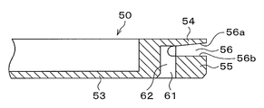
- FIG. 2 is a plan view of the cleaning jig 50
- FIG. 3 is a sectional view taken along line AA of FIG. 2
- FIG. 4 is a sectional view taken along line BB
- FIG. 5 is a sectional view taken along line CC.
- the jig 50 has a disk-like shape as a whole, and the outer dimensions other than the thickness are the same shape and the same size as the wafer.
- An annular recess 52 is formed in the peripheral portion on the upper surface side of the cleaning jig 50.
- An annular flat bottom 53 facing the recess 52 is formed on the lower surface side of the recess 52.
- An annular peripheral ceiling portion 54 is provided on the outside of the annular recess 52 of the cleaning jig 50 so as to project outward over the entire circumference.
- an annular peripheral bottom portion 55 that continues from the bottom portion 53 and projects outward over the entire circumference is formed.
- An annular discharge port 56 is formed between the peripheral ceiling portion 54 and the peripheral bottom portion 55 over the entire circumference of the cleaning jig 50.
- the discharge port 56 is formed by the peripheral ceiling portion 54 and the peripheral bottom portion 55.
- a discharge port 56 may be separately formed between the peripheral ceiling portion 54 and the peripheral bottom portion 55.
- arcuate holes 61 are formed at equal intervals in a plan view as shown in FIGS. 2 and 5.
- the cleaning jig 50 is formed at 12 locations.
- the hole 61 is formed in the peripheral bottom portion 55 with a length reaching the inner portion of the discharge port 56 in the height direction.
- a taxiway 62 leading from the entrance of the hole 61 to the discharge port 56 is formed.
- the discharge port 56 has an upper surface 56a and a lower surface 56b.
- the taxiway 62 has a shape in which the cross-sectional area of the flow path increases toward the discharge port 56.
- each hole 61 is formed independently of each other up to at least the lower surface 56b in each discharge port 56. Further, each hole 61 communicates with the lower surface 56b in the discharge port 56 at a position closer to the center of the cleaning jig 50 in a plan view.
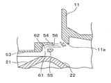
- FIG. 6 shows the positional relationship between the peripheral portion of the cleaning jig 50 when the cleaning jig 50 having such a structure is held by the spin chuck 4 and the block body 11 and the inner cup 20 of the outer cup 10.
- the lower surface side of the peripheral ceiling portion 54 that is, the upper surface 56a in the discharge port 56 is inclined and is directed obliquely upward from the horizontal plane at an elevation angle ⁇ .
- This elevation angle ⁇ can be arbitrarily set in the range of, for example, 5 degrees to 20 degrees.
- the lower end portion 11a of the block body 11 is set to be located within the range of the elevation angle ⁇ .
- the position of the upper end 11b of the block body 11 is the elevation angle of the peripheral ceiling portion of the cleaning jig 50 held by the spin chuck 4, and more specifically, the upper surface in the discharge port 56. It is located above the extension line of 56a. In this example, the upper end 11b of the block body 11 is located above the range of the elevation angle ⁇ .
- the cleaning jig 50 according to the embodiment has the above configuration. Next, a cleaning method using the cleaning jig 50 will be described.
- the wafer is carried out from the housing 2 of the rotary coating device 1.
- the cleaning jig 50 is carried into the housing 2 and held by the spin chuck 4.
- the cleaning jig 50 has the same shape and size as the wafer except for the thickness, so that the transfer arm for transporting the wafer can be used as it is. Further, while the cleaning jig 50 is not used, it can be kept on standby at a wafer storage location such as a buffer unit or a storage cabinet in a coating development processing apparatus on which this type of rotary coating device 1 is mounted.
- the cleaning liquid is supplied from the cleaning nozzle 31 toward the bottom portion 53 of the lower surface of the cleaning jig 50. Then, as shown in FIG. 7, the cleaning liquid flows along the surface of the bottom portion 53 to the outer peripheral side, and a part of the cleaning liquid falls to the inner slope portion 21 and the outer slope portion 22 of the inner cup 20. These surfaces are cleaned with a cleaning solution.
- the supply to the inner slope portion 21 and the outer slope portion 22 is controlled by, for example, the discharge flow rate of the cleaning liquid and the rotation speed of the cleaning jig 50.
- each hole 61 communicates with the lower surface 56b in the discharge port 56 at a position closer to the center of the cleaning jig 50 in a plan view, so that a larger amount of cleaning liquid is stored from the inner part of the hole 61. As a result, the amount of the liquid pool T to be stored can be increased.
- the cleaning jig 50 is then rotated at a relatively high rotation speed. Then, as shown in FIG. 8, the pool T of the cleaning liquid formed from the entrance of the hole 61 of the cleaning jig 50 to the guideway 62 is pushed out by centrifugal force and is pushed out from the discharge port 56. It scatters toward the lower end 11a of the block body 11 of the outer cup 10. As a result, the lower end portion 11a of the block body 11 and its peripheral region are cleaned.
- the cleaning liquid can be supplied in the scattering direction toward each of the block body 11 and the inner cup 20, and efficient cleaning can be performed without being affected by each other's dirty state. Is.
- the cleaning liquid rises from the bottom 53 of the cleaning jig 50 to the lower surface 56b in the discharge port 56. When it comes, it flows through a short flow path without interfering with each other, so that it is easy to guide the cleaning liquid to the inner space of the discharge port 56. Further, by adjusting the elevation angle ⁇ shown in FIG. 6, it is possible to adjust the scattering region of such a cleaning liquid in the height direction.
- the maximum angle of the elevation angle ⁇ is higher than the extension line on the lower surface side of the peripheral ceiling portion 54, and the upper end portion of the outer cup 10 (the upper end 11b of the block body 11 in the present embodiment) is located. That's good. As a result, it is possible to more reliably prevent the mist of the cleaning liquid scattered from the discharge port 56 from being scattered to the outside of the outer cup 10.
- the guideway 62 has a shape in which the cross-sectional area of the flow path increases toward the discharge port 56, so that the cleaning liquid in the liquid pool T is prevented from being scattered outward by centrifugal force. Therefore, it is possible to suitably scatter the cleaning liquid of the liquid pool T.
- the holes 61 have an arc shape in a plan view, but of course, the holes are not limited to this, and holes of other shapes can be adopted, and the number of holes 61 to be installed is also the present embodiment. Not limited to. Further, the sizes of the holes do not have to be the same, and the large and small holes may be arranged in combination. Thereby, the amount of the cleaning liquid scattered toward the outer cup 10 can be changed during the cleaning treatment, and an appropriate cleaning effect can be realized depending on the condition of the coating liquid adhering to the outer cup 10. From this point of view, the holes 61 do not necessarily have to be installed at equal intervals.
- the peripheral ceiling portion 54 and the peripheral bottom portion 55 have the same outward protrusion length, but the present invention is not limited to this, and the protrusion length toward the peripheral bottom portion 55 is set to the peripheral edge. It may be longer than the protruding length of the ceiling portion 54. As a result, the scattering direction of the liquid pool T can be ordered and scattered upward.
- Rotating coating device 3 Container 10 Outer cup 20 Inner cup 50 Cleaning jig 54 Peripheral ceiling 55 Peripheral bottom 56 Discharge port 61 Hole 62 Taxiway 100 Control unit T Liquid pool
Abstract
Description
まず、実施形態にかかる洗浄用治具を用いて容器が洗浄される回転塗布装置の構成について説明する。図1に示したように、塗布装置としての回転塗布装置1は、例えば直方体の筐体2を有しており、この筐体2内に、容器3が収容されている。容器3は、外カップ10と内カップ20とを有している。 <Rotary coating device>
First, a configuration of a rotary coating device for cleaning a container using the cleaning jig according to the embodiment will be described. As shown in FIG. 1, the
次に実施の形態にかかる洗浄用治具50について詳述する。図2は洗浄用治具50の平面図、図3は図2のA-A線断面図、図4は同B-B線断面図、図5は同C-C線断面図であり、洗浄用治具50は全体として円盤状の形状を有し、厚み以外の外寸はウェハと同形同大である。 <Cleaning jig>
Next, the cleaning
実施の形態にかかる洗浄用治具50は以上の構成を有しており。次にこの洗浄用治具50を用いた洗浄方法について説明する。 <Washing method>
The cleaning
また前記実施の形態では、複数の孔61は互いに独立して吐出口56内の下面56bまで形成されているので、洗浄用治具50の底部53から吐出口56内の下面56bまで洗浄液が上がってくる際に、互いに干渉することなく短い流路を流れるため、吐出口56内空間まで洗浄液を誘導しやすくなっている。
さらに図6に示した仰角θを調整することで、そのような洗浄液の高さ方向の飛散領域を調整することが可能である。かかる場合、仰角θの最大角度は、周縁天井部54の下面側の延長線上よりも高い位置に、外カップ10の上端部(本実施の形態ではブロック体11の上端11b)が位置していることがよい。これによって吐出口56から飛散した洗浄液のミストが外カップ10の外側に飛散することをより確実に防止できる。 Therefore, it is possible to clean a wider area in the height direction as compared with the method in which the cleaning liquid is scattered in the horizontal direction. Further, as described above, the cleaning liquid flows along the surface of the
Further, in the above-described embodiment, since the plurality of
Further, by adjusting the elevation angle θ shown in FIG. 6, it is possible to adjust the scattering region of such a cleaning liquid in the height direction. In such a case, the maximum angle of the elevation angle θ is higher than the extension line on the lower surface side of the
3 容器
10 外カップ
20 内カップ
50 洗浄用治具
54 周縁天井部
55 周縁底部
56 吐出口
61 孔
62 誘導路
100 制御部
T 液だまり 1 Rotating
Claims (17)
- 容器内に配置された回転保持装置に保持された基板の上に処理液を供給し、前記基板の回転によって前記基板上に前記処理液の膜を形成する回転塗布装置における、前記回転保持装置に基板と同様に保持された状態で前記容器内の洗浄に用いる円盤状の洗浄用治具であって、
前記洗浄用治具の周縁部には周縁天井部と周縁底部とが全周に亘って形成され、
前記周縁天井部と周縁底部との間には吐出口が全周に亘って形成され、
前記周縁底部には、前記吐出口に通ずる孔が、周方向に間隔をおいて複数形成され、
前記周縁天井部の下面は、外周上方に向けて斜めに傾斜している、洗浄用治具。 To the rotation holding device in a rotation coating device in which a treatment liquid is supplied onto a substrate held by a rotation holding device arranged in a container and a film of the treatment liquid is formed on the substrate by rotation of the substrate. A disk-shaped cleaning jig used for cleaning the inside of the container while being held in the same manner as the substrate.
A peripheral ceiling portion and a peripheral bottom portion are formed on the peripheral edge portion of the cleaning jig over the entire circumference.
A discharge port is formed over the entire circumference between the peripheral ceiling portion and the peripheral bottom portion.
A plurality of holes leading to the discharge port are formed at the bottom of the peripheral edge at intervals in the circumferential direction.
A cleaning jig in which the lower surface of the peripheral ceiling portion is inclined diagonally toward the upper side of the outer circumference. - 前記周縁天井部と周縁底部とによって前記吐出口が形成されている、請求項1に記載の洗浄用治具。 The cleaning jig according to claim 1, wherein the discharge port is formed by the peripheral ceiling portion and the peripheral bottom portion.
- 前記孔の入り口部と前記吐出口との間に形成される誘導路は、前記吐出口に向かうにつれて流路断面積が大きくなる形状を有する、請求項1または2に記載の洗浄用治具。 The cleaning jig according to claim 1 or 2, wherein the taxiway formed between the entrance portion of the hole and the discharge port has a shape in which the cross-sectional area of the flow path increases toward the discharge port.
- 前記孔は、平面視で円弧状である、請求項1~3のいずれか一項に記載の洗浄用治具。 The cleaning jig according to any one of claims 1 to 3, wherein the hole is arcuate in a plan view.
- 前記周縁天井部よりも前記周縁底部の方が外側に突出している、請求項1~4のいずれか一項に記載の洗浄用治具。 The cleaning jig according to any one of claims 1 to 4, wherein the peripheral bottom portion projects outward from the peripheral ceiling portion.
- 前記複数の孔は互いに独立して前記吐出口内の下面まで形成されている、請求項1~5に記載の洗浄用治具。 The cleaning jig according to claim 1 to 5, wherein the plurality of holes are formed independently of each other up to the lower surface in the discharge port.
- 前記孔は、前記吐出口内の下面に対して、平面視で前記洗浄用治具の中央寄りの位置で連通している、請求項1~6のいずれかに記載の洗浄用治具。 The cleaning jig according to any one of claims 1 to 6, wherein the hole communicates with the lower surface of the discharge port at a position closer to the center of the cleaning jig in a plan view.
- 容器内の基板の上に塗布液を供給し、前記基板の回転によって前記基板上に前記塗布液の膜を形成する塗布装置であって、
前記容器内に配置され、前記塗布液が供給される前記基板と同様に円盤状の洗浄用治具を保持可能な回転保持装置と、
前記容器内を洗浄するために、前記回転保持装置によって保持および回転される前記洗浄用治具の下面に洗浄液を供給する洗浄ノズルと、を備え、
前記洗浄用治具の周縁部には周縁天井部と周縁底部とが全周に亘って形成され、
前記周縁天井部と周縁底部との間には吐出口が全周に亘って形成され、
前記周縁底部には、前記吐出口に通ずる孔が、周方向に間隔をおいて複数形成され、
前記天井部の下面は、外周上方に向けて斜めに傾斜している、塗布装置。 A coating device that supplies a coating liquid onto a substrate in a container and forms a film of the coating liquid on the substrate by rotating the substrate.
A rotation holding device arranged in the container and capable of holding a disk-shaped cleaning jig in the same manner as the substrate to which the coating liquid is supplied.
A cleaning nozzle for supplying a cleaning liquid to the lower surface of the cleaning jig held and rotated by the rotation holding device for cleaning the inside of the container is provided.
A peripheral ceiling portion and a peripheral bottom portion are formed on the peripheral edge portion of the cleaning jig over the entire circumference.
A discharge port is formed over the entire circumference between the peripheral ceiling portion and the peripheral bottom portion.
A plurality of holes leading to the discharge port are formed at the bottom of the peripheral edge at intervals in the circumferential direction.
A coating device in which the lower surface of the ceiling portion is inclined obliquely toward the upper side of the outer circumference. - 前記洗浄用治具において前記孔の入り口部と前記吐出口との間に形成される誘導路は、前記吐出口に向かうにつれて流路断面積が大きくなる形状を有する、請求項8に記載の塗布装置。 The coating according to claim 8, wherein the taxiway formed between the entrance portion of the hole and the discharge port in the cleaning jig has a shape in which the cross-sectional area of the flow path increases toward the discharge port. Device.
- 前記孔は平面視で円弧状である、請求項8または9のいずれか一項に記載の塗布装置。 The coating device according to any one of claims 8 or 9, wherein the holes are arcuate in a plan view.
- 前記周縁天井部よりも前記周縁底部の方が外側に突出している、請求項8~10のいずれか一項に記載の塗布装置。 The coating device according to any one of claims 8 to 10, wherein the peripheral bottom portion projects outward from the peripheral ceiling portion.
- 前記容器は、前記洗浄用治具を囲むカップを有し、
前記カップの上部には円筒状のブロック体が設けられ、
前記ブロック体の上端の位置は、前記回転保持部に保持された前記洗浄用治具の前記周縁天井部の仰角よりも上側に位置している、請求項8~11に記載の塗布装置。 The container has a cup that surrounds the cleaning jig.
A cylindrical block body is provided on the upper part of the cup.
The coating device according to claim 8 to 11, wherein the position of the upper end of the block body is located above the elevation angle of the peripheral ceiling portion of the cleaning jig held by the rotation holding portion. - 前記周縁天井部の仰角の範囲内に前記ブロック体の下端が位置している、請求項12に記載の塗布装置。 The coating device according to claim 12, wherein the lower end of the block body is located within the range of the elevation angle of the peripheral ceiling portion.
- 前記容器は、前記保持装置に保持された前記洗浄用治具の下方であって前記外周円筒部より内側に位置する内カップを有し、
前記ブロック体に対しては、前記孔を通じて前記洗浄液が供給され、
前記内カップに対しては、前記孔以外の前記洗浄用治具の底部を通じて、前記洗浄液が供給される、請求項12~13に記載の塗布装置。 The container has an inner cup located below the cleaning jig held by the holding device and inside the outer cylindrical portion.
The cleaning liquid is supplied to the block body through the holes.
The coating device according to claim 12 to 13, wherein the cleaning liquid is supplied to the inner cup through the bottom of the cleaning jig other than the hole. - 請求項1~7のいずれか一項に記載の洗浄用治具を用いて、前記回転塗布装置の前記容器内を洗浄する洗浄方法であって、
(A)前記回転保持装置で前記洗浄用治具を保持した状態で、前記洗浄用治具を相対的低速回転させながら、前記洗浄用治具の下面側から外側に向けて洗浄液を供給して当該洗浄液を少なくとも前記孔に到達させて、前記孔内に液だまりを形成する工程と、
(B)その後前記洗浄液の供給を停止させた状態で、前記洗浄用治具を相対的高速回転させる工程と、
を含む洗浄方法。 A cleaning method for cleaning the inside of the container of the rotary coating device using the cleaning jig according to any one of claims 1 to 7.
(A) While the cleaning jig is held by the rotation holding device, the cleaning jig is rotated at a relatively low speed, and the cleaning liquid is supplied from the lower surface side to the outside of the cleaning jig. A step of allowing the cleaning liquid to reach at least the pores to form a liquid pool in the pores.
(B) After that, in a state where the supply of the cleaning liquid is stopped, the step of rotating the cleaning jig at a relatively high speed and
Cleaning methods including. - 前記(A)工程では、供給された洗浄液の一部によって、前記容器内における前記洗浄用治具の下方領域を洗浄する、請求項15に記載の洗浄方法。 The cleaning method according to claim 15, wherein in the step (A), a part of the supplied cleaning liquid is used to clean the lower region of the cleaning jig in the container.
- 前記(A)工程と前記(B)工程とを繰り返して行う、請求項15または16のいずれか一項に記載の洗浄方法。 The cleaning method according to any one of claims 15 or 16, wherein the step (A) and the step (B) are repeated.
Priority Applications (3)
| Application Number | Priority Date | Filing Date | Title |
|---|---|---|---|
| KR1020227036063A KR20220158755A (en) | 2020-03-27 | 2021-03-15 | Cleaning jig, application device and cleaning method |
| JP2022509953A JPWO2021193200A1 (en) | 2020-03-27 | 2021-03-15 | |
| CN202180021928.6A CN115298801A (en) | 2020-03-27 | 2021-03-15 | Cleaning jig, coating device and cleaning method |
Applications Claiming Priority (2)
| Application Number | Priority Date | Filing Date | Title |
|---|---|---|---|
| JP2020057079 | 2020-03-27 | ||
| JP2020-057079 | 2020-03-27 |
Publications (1)
| Publication Number | Publication Date |
|---|---|
| WO2021193200A1 true WO2021193200A1 (en) | 2021-09-30 |
Family
ID=77892119
Family Applications (1)
| Application Number | Title | Priority Date | Filing Date |
|---|---|---|---|
| PCT/JP2021/010392 WO2021193200A1 (en) | 2020-03-27 | 2021-03-15 | Cleaning jig, application device, and cleaning method |
Country Status (5)
| Country | Link |
|---|---|
| JP (1) | JPWO2021193200A1 (en) |
| KR (1) | KR20220158755A (en) |
| CN (2) | CN115298801A (en) |
| TW (1) | TW202141576A (en) |
| WO (1) | WO2021193200A1 (en) |
Citations (4)
| Publication number | Priority date | Publication date | Assignee | Title |
|---|---|---|---|---|
| JPH02252232A (en) * | 1989-03-25 | 1990-10-11 | Tokyo Electron Ltd | Resist coater |
| JPH0766116A (en) * | 1993-08-23 | 1995-03-10 | Tokyo Electron Ltd | Coater |
| JP2010016315A (en) * | 2008-07-07 | 2010-01-21 | Tokyo Electron Ltd | Jig and method for cleaning of rotary coating apparatus |
| JP2014033178A (en) * | 2012-07-11 | 2014-02-20 | Tokyo Electron Ltd | Liquid processing apparatus, cleaning jig and cleaning method |
-
2021
- 2021-03-15 KR KR1020227036063A patent/KR20220158755A/en active Search and Examination
- 2021-03-15 TW TW110109079A patent/TW202141576A/en unknown
- 2021-03-15 JP JP2022509953A patent/JPWO2021193200A1/ja active Pending
- 2021-03-15 WO PCT/JP2021/010392 patent/WO2021193200A1/en active Application Filing
- 2021-03-15 CN CN202180021928.6A patent/CN115298801A/en active Pending
- 2021-03-19 CN CN202120566987.9U patent/CN215466779U/en active Active
Patent Citations (4)
| Publication number | Priority date | Publication date | Assignee | Title |
|---|---|---|---|---|
| JPH02252232A (en) * | 1989-03-25 | 1990-10-11 | Tokyo Electron Ltd | Resist coater |
| JPH0766116A (en) * | 1993-08-23 | 1995-03-10 | Tokyo Electron Ltd | Coater |
| JP2010016315A (en) * | 2008-07-07 | 2010-01-21 | Tokyo Electron Ltd | Jig and method for cleaning of rotary coating apparatus |
| JP2014033178A (en) * | 2012-07-11 | 2014-02-20 | Tokyo Electron Ltd | Liquid processing apparatus, cleaning jig and cleaning method |
Also Published As
| Publication number | Publication date |
|---|---|
| CN215466779U (en) | 2022-01-11 |
| JPWO2021193200A1 (en) | 2021-09-30 |
| CN115298801A (en) | 2022-11-04 |
| KR20220158755A (en) | 2022-12-01 |
| TW202141576A (en) | 2021-11-01 |
Similar Documents
| Publication | Publication Date | Title |
|---|---|---|
| US11837477B2 (en) | Washing device and washing method | |
| KR101990161B1 (en) | Fluid processing device | |
| JP6740028B2 (en) | Substrate processing apparatus, substrate processing method and storage medium | |
| US9865483B2 (en) | Substrate liquid processing method, substrate liquid processing apparatus, and recording medium | |
| US7247209B2 (en) | Dual outlet nozzle for the combined edge bead removal and backside wash of spin coated wafers | |
| JP2003275696A (en) | Substrate washing apparatus and substrate washing method | |
| US10279368B2 (en) | Coating method and coating apparatus | |
| JPH07106233A (en) | Rotary type substrate treater | |
| JP5516447B2 (en) | Liquid processing apparatus, liquid processing method, and storage medium | |
| KR20080071685A (en) | Support member and apparatus for treating substrate with the same | |
| US10707098B2 (en) | Substrate processing apparatus, substrate processing method and memory medium | |
| JP7073658B2 (en) | Board processing method, board processing device, and storage medium | |
| JP2015170617A (en) | Liquid processing apparatus | |
| WO2021193200A1 (en) | Cleaning jig, application device, and cleaning method | |
| JP6961362B2 (en) | Board processing equipment | |
| JPH05259060A (en) | Applicator | |
| JP7202901B2 (en) | Coating film forming method and coating film forming apparatus | |
| JP2022062395A (en) | Liquid processing device and cleaning method | |
| US20170287743A1 (en) | Substrate treating device and substrate treating method | |
| WO2022153887A1 (en) | Coating apparatus, coating method, and computer recording medium | |
| US11923218B2 (en) | Development processing apparatus and development processing method | |
| JP2021132103A (en) | Substrate processing method and substrate processing device | |
| TW202200273A (en) | Substrate processing device and substrate processing method | |
| JP2020102508A (en) | Substrate processing apparatus |
Legal Events
| Date | Code | Title | Description |
|---|---|---|---|
| 121 | Ep: the epo has been informed by wipo that ep was designated in this application |
Ref document number: 21775490 Country of ref document: EP Kind code of ref document: A1 |
|
| ENP | Entry into the national phase |
Ref document number: 2022509953 Country of ref document: JP Kind code of ref document: A |
|
| WWE | Wipo information: entry into national phase |
Ref document number: 17914108 Country of ref document: US |
|
| ENP | Entry into the national phase |
Ref document number: 20227036063 Country of ref document: KR Kind code of ref document: A |
|
| NENP | Non-entry into the national phase |
Ref country code: DE |
|
| 122 | Ep: pct application non-entry in european phase |
Ref document number: 21775490 Country of ref document: EP Kind code of ref document: A1 |