WO2021193152A1 - トランクスタイプ使い捨て着用物品 - Google Patents
トランクスタイプ使い捨て着用物品 Download PDFInfo
- Publication number
- WO2021193152A1 WO2021193152A1 PCT/JP2021/010130 JP2021010130W WO2021193152A1 WO 2021193152 A1 WO2021193152 A1 WO 2021193152A1 JP 2021010130 W JP2021010130 W JP 2021010130W WO 2021193152 A1 WO2021193152 A1 WO 2021193152A1
- Authority
- WO
- WIPO (PCT)
- Prior art keywords
- region
- sheet layer
- sheet
- leg
- convex
- Prior art date
- Legal status (The legal status is an assumption and is not a legal conclusion. Google has not performed a legal analysis and makes no representation as to the accuracy of the status listed.)
- Ceased
Links
Images


Classifications
-
- A—HUMAN NECESSITIES
- A61—MEDICAL OR VETERINARY SCIENCE; HYGIENE
- A61F—FILTERS IMPLANTABLE INTO BLOOD VESSELS; PROSTHESES; DEVICES PROVIDING PATENCY TO, OR PREVENTING COLLAPSING OF, TUBULAR STRUCTURES OF THE BODY, e.g. STENTS; ORTHOPAEDIC, NURSING OR CONTRACEPTIVE DEVICES; FOMENTATION; TREATMENT OR PROTECTION OF EYES OR EARS; BANDAGES, DRESSINGS OR ABSORBENT PADS; FIRST-AID KITS
- A61F13/00—Bandages or dressings; Absorbent pads
- A61F13/15—Absorbent pads, e.g. sanitary towels, swabs or tampons for external or internal application to the body; Supporting or fastening means therefor; Tampon applicators
- A61F13/45—Absorbent pads, e.g. sanitary towels, swabs or tampons for external or internal application to the body; Supporting or fastening means therefor; Tampon applicators characterised by the shape
- A61F13/49—Absorbent pads, e.g. sanitary towels, swabs or tampons for external or internal application to the body; Supporting or fastening means therefor; Tampon applicators characterised by the shape specially adapted to be worn around the waist, e.g. diapers, nappies
- A61F13/496—Absorbent pads, e.g. sanitary towels, swabs or tampons for external or internal application to the body; Supporting or fastening means therefor; Tampon applicators characterised by the shape specially adapted to be worn around the waist, e.g. diapers, nappies in the form of pants or briefs
-
- A—HUMAN NECESSITIES
- A61—MEDICAL OR VETERINARY SCIENCE; HYGIENE
- A61F—FILTERS IMPLANTABLE INTO BLOOD VESSELS; PROSTHESES; DEVICES PROVIDING PATENCY TO, OR PREVENTING COLLAPSING OF, TUBULAR STRUCTURES OF THE BODY, e.g. STENTS; ORTHOPAEDIC, NURSING OR CONTRACEPTIVE DEVICES; FOMENTATION; TREATMENT OR PROTECTION OF EYES OR EARS; BANDAGES, DRESSINGS OR ABSORBENT PADS; FIRST-AID KITS
- A61F13/00—Bandages or dressings; Absorbent pads
- A61F13/15—Absorbent pads, e.g. sanitary towels, swabs or tampons for external or internal application to the body; Supporting or fastening means therefor; Tampon applicators
- A61F13/51—Absorbent pads, e.g. sanitary towels, swabs or tampons for external or internal application to the body; Supporting or fastening means therefor; Tampon applicators characterised by the outer layers of the pads
Definitions
- the present invention relates to a trunks type disposable wear article in which the fit of the leg tube portion can be changed.
- Pants-type disposable diapers have a waist opening and a pair of leg openings, an exterior that extends from the edge of the front waist opening to the edge of the rear waist opening, and an absorber provided at least in the crotch area of this exterior.
- a structure having an interior body including the above and side seal portions for joining both front side portions and rear side side portions of the exterior body is common.
- trunks-type (also called one-quarter length or boxer-type) disposable diapers having a pair of leg cylinders surrounding the base side of the thigh are also known (for example, Patent Document 1, Patent Document 1, 2).
- an elastic member In trunks type disposable diapers, by attaching an elastic member to the leg tube, an elastic region that elastically expands and contracts in the circumferential direction is provided in the leg tube.
- an elongated elastic member such as rubber thread is generally used as the elastic member attached to the leg tube portion.
- the present inventor increases the number of elastic members per unit contact area of the leg tube portion by turning over the leg tube portion as necessary and stacking the leg tube portions in a double layer or the like. Therefore, it was found that the tightening pressure can be increased.
- the main object of the present invention is to suppress an increase in thickness when the elastic leg tube portion is turned over.
- the trunks type disposable wear items that have solved the above problems are as follows. ⁇ First aspect> It has a pair of leg tubes that surround the base of the thigh. Convex regions and concave regions are alternately and repeatedly provided in the leg tube portion while being adjacent to each other in the leg length direction orthogonal to the circumferential direction.
- the convex region and the concave region are regions in which the first sheet layer and the second sheet layer are overlapped.
- the convex region has a joint portion between the first sheet layer and the second sheet layer, which is not joined to the first sheet layer and the second sheet layer, or is provided at intervals.
- the concave region has a joint portion between the first sheet layer and the second sheet layer provided at intervals.
- An elastic sheet is provided between the first sheet layer and the second sheet layer at least in the concave region.
- the first sheet layer and the second sheet layer in the convex region and the concave region have folds formed by expanding in opposite directions while contracting in the expansion / contraction direction together with the elastic sheet.
- the distance between the joints in the expansion and contraction direction is wider than that in the concave region.
- the convex region and the concave region have constant dimensions in the leg length direction, respectively.
- the dimension of the convex region in the leg length direction is equal to or less than the dimension of the concave region in the leg length direction. Trunks type disposable wear goods characterized by that.
- convex regions and concave regions are alternately and repeatedly provided adjacent to each other in the leg length direction.
- at least the concave region has an elastic sheet, and the first sheet layer and the second sheet layer in the convex region and the concave region are opposite to each other while contracting in the expansion / contraction direction together with the elastic sheet in the natural length and the state of being contracted to some extent. It has folds that bulge in the direction. Even if the convex region alone does not expand or contract from the concave region (including the case where it does not have an elastic member such as an elastic sheet), it contracts together with the adjacent concave region to form folds.
- the convex region has a wider distance in the expansion / contraction direction of the joint than the concave region, the convex region is higher than the concave region at least in the mounted state (for example, in the state of extending to half of the maximum elongation in the expansion / contraction direction). Large folds will be formed. Therefore, one of the convex region and the concave region is relatively convex and the other is relatively concave due to the difference in thickness (difference in maximum elongation) due to the folds in the contracted state.
- the convex region and the concave region can be engaged with each other when the wearer turns the leg tube portion and overlaps the leg cylinder portion in a double manner or the like. Therefore, the tightening pressure can be increased while suppressing the increase in thickness.
- the meshing of the convex region and the concave region also brings an advantage that the rolled-up portion is less likely to shift.
- the elastic sheet is provided in the convex region and the concave region, and is provided in the convex region and the concave region.
- the arrangement pattern of the joint portion in the convex region and the arrangement pattern of the joint portion in the concave region are different.
- the trunks type disposable wear article of the first aspect is provided in the convex region and the concave region.
- the convex region is provided at the end of the leg tube portion on the leg opening side.
- the maximum elongation of the convex region in the expansion and contraction direction is 200 to 350%, and the maximum elongation of the concave region in the expansion and contraction direction is 0.70 to 0.95 times the maximum elongation of the convex region in the expansion and contraction direction.
- Trunks type disposable wear article of the second or third aspect Trunks type disposable wear article of the second or third aspect.
- the convex region and the concave region have an elastic sheet, one is convex and the other is concave due to the difference in maximum elongation. Therefore, the maximum elongation of the convex region and the concave region may be appropriately adjusted according to the degree of engagement desired in the convex region and the concave region, but it is usually preferable to be within the range of this embodiment.
- An exterior body having a waist opening and a pair of leg openings extending from the edge of the front waist opening to the edge of the rear waist opening, and an interior body including an absorber provided at least in the crotch portion of the exterior body. It has a side seal portion that joins both front side portions and rear side side portions of the exterior body. An annular waist circumference is formed between one side seal portion in the width direction and the other side seal portion in the exterior body.
- the crotch portion of the exterior body has a pair of inner thigh contact portions extending outward in the width direction from both side edges of the absorber, and a portion along the edge of the leg opening including these inner thigh contact portions. However, it is the leg tube part.
- a region extending from the leg tube portion to at least one of the front and rear waist circumference portions is a region having the first sheet layer, the second sheet layer, and the elastic sheet.
- the trunks type disposable wear article having the same basic structure as the pants type disposable wear article without the leg tube portion as in this embodiment, the first sheet layer and the second sheet layer common from the waist circumference to the leg tube portion. It is preferable because the sheet layer and the elastic sheet can be arranged to add elasticity.
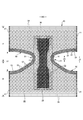
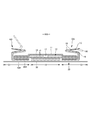
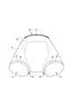
- FIG. 3 is a cross-sectional view taken along the line 3-3 of FIG. It is a perspective view seen from the front diagonally lower side with the trunks type disposable diaper attached. It is a top view which shows the main part of the trunks type disposable diaper in an expanded state in an enlarged manner.
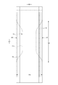
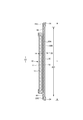
- FIG. 1 It is a top view which shows the main part of the trunks type disposable diaper in an expanded state in an enlarged manner. It is a front schematic diagram for demonstrating the usage method. It is a top view which shows the main part of the trunks type disposable diaper in an expanded state in an enlarged manner. It is a plan view (outer surface side) of a trunks type disposable diaper in an unfolded state.
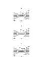
- A is a plan view of a main part of the stretchable region in the expanded state
- (b) is a cross-sectional view taken along the line DD of (a)
- (c) is a cross-sectional view taken in the mounted state
- (d) is a cross-sectional view taken in the natural length state. be.
- A is a plan view of a main part of a non-stretchable region
- (b) is a cross-sectional view taken along the line DD of (a)
- (c) is a cross-sectional view taken in a mounted state
- (d) is a cross-sectional view taken in a natural length state.
- It is a main part plan view of a non-stretchable region. It is sectional drawing which shows roughly the cross section of the main part of the exterior body extended to some extent.
- FIGS. 1 to 10 show trunks-type disposable diapers (hereinafter, also simply referred to as diapers) as an example of trunks-type disposable wear articles having a pair of leg cylinders 50.
- the hot melt adhesive can be applied by a known method such as slot coating, continuous linear or dotted bead coating, spiral or Z-shaped spray coating, or pattern coating (transfer of hot melt adhesive by letterpress method). Can be applied.
- a hot melt adhesive can be applied to the outer peripheral surface of the elastic member to fix the elastic member to the adjacent member.
- hot melt adhesive examples include EVA type, adhesive rubber type (elastomer type), olefin type, polyester / polyamide type and the like, but they can be used without particular limitation.
- a joining means for joining each component a means by material welding such as a heat seal or an ultrasonic seal can also be used.
- the pair of leg tube portions 50 of the trunks type disposable diaper is not particularly limited as long as it has a tubular shape surrounding the thigh in the worn state, and the structures described in Patent Documents 1 and 2 can be adopted.
- the trunks type disposable diaper shown in the illustrated example adopts a structure simpler than that described in Patent Documents 1 and 2.
- the trunks type disposable diaper of the illustrated example has a waist opening WO and a pair of leg openings LO, and an exterior body 20 extending from the edge of the waist opening WO of the front body F to the edge of the waist opening WO of the back body B.
- an interior body 10 including an absorber 13 provided at least in the crotch portion 28 of the exterior body 20, and side seal portions 21 for joining both front side portions and rear side side portions of the exterior body 20. It is a thing.
- the crotch portion 28 of the exterior body 20 has a pair of inner thigh contact portions 51 extending from both side edges of the absorber 13 to one side and the other side of the WD in the width direction, respectively, and these inner thigh contact portions 51 are provided.
- the portion along the edge 29 of the leg opening including the leg opening is a pair of leg tube portions 50 surrounding the base side of the thigh.
- a joining means such as a hot melt adhesive
- the interior body 10 and the exterior body 20 are the boundaries between the front body F and the back body B in the front-rear direction LD.
- a waist opening WO and a pair of leg openings LO are formed by folding at the center (vertical direction) and joining both side portions to each other by heat welding or hot melt adhesive to form a side seal portion 21. It becomes a trunks type disposable diaper.
- the interior body 10 has an absorber 13 interposed between the liquid-permeable top sheet 11 made of a non-woven fabric or the like and the liquid-impermeable sheet 12 made of polyethylene or the like. It has a structure and absorbs and retains the excrement liquid that has passed through the top sheet 11.
- the planar shape of the interior body 10 is not particularly limited, but it is generally a substantially rectangular shape as shown in the illustrated form.
- a perforated or non-perforated non-woven fabric, a perforated plastic sheet, or the like is preferably used.
- the material fibers constituting the non-woven fabric can be olefin-based fibers such as polyethylene or polypropylene, synthetic fibers such as polyester-based and polyamide-based, recycled fibers such as rayon and cupra, and natural fibers such as cotton.
- a non-woven fabric obtained by an appropriate processing method such as a spun bond method, a thermal bond method, a melt blown method, or a needle punch method can be used.
- the spunlace method is excellent in that it is rich in flexibility and drapeability, and the thermal bond method is excellent in that it is bulky and soft.
- the top sheet 11 involves the side edge portion of the absorber 13 and extends to the back surface side of the absorber 13, but is not limited to this.
- liquid-impermeable sheet 12 covering the back side of the absorber 13 a liquid-impermeable plastic sheet such as polyethylene or polypropylene is used, but in recent years, a liquid-impermeable sheet having moisture permeability is preferably used from the viewpoint of preventing stuffiness.
- the water-impervious / moisture-permeable sheet is a microporous sheet obtained by melting and kneading an inorganic filler in an olefin resin such as polyethylene or polypropylene to form a sheet, and then stretching the sheet in a uniaxial or biaxial direction. Can be mentioned.
- the liquid impermeable sheet 12 it is desirable to use an opaque sheet so that brown color such as defecation and urine does not appear.
- a plastic in which pigments such as calcium carbonate, titanium oxide, zinc oxide, white carbon, clay, talc, and barium sulfate and a filler are added and formed into a film is preferably used.
- the liquid impermeable sheet 12 is folded back on both sides in the width direction of the absorber 13 together with the top sheet 11, but the present invention is not limited to this.
- the absorber 13 is basically a known material, for example, a stack of pulp fibers, an aggregate of filaments such as cellulose acetate, or a non-woven fabric, and a highly absorbent polymer is mixed and fixed as necessary. Can be used.
- the absorber 13 can be packaged with a liquid-permeable and liquid-retaining packaging sheet 14 such as crepe paper, if necessary, in order to retain the shape and polymer.
- the overall shape of the absorber 13 is formed in a substantially hourglass shape having a constricted portion 13N narrower than both front and rear sides in the front-rear direction range including the crotch portion 28, but the overall shape should be an appropriate shape such as a rectangular shape. Can be done.
- the dimensions of the constricted portion 13N can be appropriately determined, but the length of the constricted portion 13N in the front-rear direction can be about 20 to 50% of the total length of the diaper, and the width of the narrowest portion 13 m is the total width 13 w of the absorber 13. It can be about 40 to 60% of.
- the portion of the interior body 10 corresponding to the constricted portion 13N of the absorber 13 does not have the absorber 13. A part is formed.
- the three-dimensional gather BS has a fixed portion fixed to the side portion of the back surface of the interior body 10, and the surface of the interior body 10 from this fixed portion via the side of the interior body 10.
- the main body portion extending to the side portion of the main body, the inverted portion formed by fixing the front and rear ends of the main body portion to the side portion of the surface of the interior body 10 in an inverted state, and the portion of this inverted portion are not fixed.
- the formed free portion is formed by a gather sheet 15 that is doubled by folding back.
- a non-woven fabric having water repellency is preferably used.
- an elongated gather elastic member 16 is arranged at the tip of a free portion or the like.
- the gather elastic member 16 is for forming a three-dimensional gather BS by erecting a free portion by an elastic elastic force as shown by a two-dot chain line in FIG. 5 in a product state.
- the gather elastic member 16 materials such as styrene rubber, olefin rubber, urethane rubber, ester rubber, polyurethane, polyethylene, polystyrene, styrene butadiene, silicone, and polyester, which are usually used, can be used. Further, in order to make it difficult to see from the outside, it is preferable to arrange the thickness at 925 dtex or less, the elongation rate at 150 to 350%, and the interval at 10.0 mm or less. As the gather elastic member 16, a tape-shaped member having a certain width can be used in addition to the thread-shaped member as shown in the illustrated figure.
- the non-woven fabric used for the gather sheet 15 is not particularly limited, and is made of olefin-based fibers such as polyethylene or polypropylene, synthetic fibers such as polyester-based and polyamide-based, recycled fibers such as rayon and cupra, and natural fibers such as cotton. It can also be produced by an appropriate processing method such as a spunbond method, a thermal bond method, a melt blown method, or a needle punch method.
- the exterior body 20 has a substantially hourglass shape in which the middle of the LD in the front-rear direction is constricted, and both side edges of the constriction are edges 29 of the leg openings, respectively.
- the crotch portion 28 of the exterior body 20 has a pair of inner thigh contact portions 51 extending from both side edges of the absorber 13 to one side and the other side of the WD in the width direction, respectively.
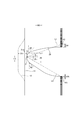
- the dimensions of the inner thigh contact portion 51 may be appropriately determined according to the length of the leg tube portion 50, but usually, the width 51x of the inner thigh contact portion 51 in the narrowest portion of the exterior body 20 is a diaper. It is preferably about 1 to 5% of the total length Y. Further, as shown in FIG. 9, in the front body F, the width direction is at an angle ⁇ 1 of 20 degrees with respect to the width direction from the virtual point P1 located on the edge 29 of the leg opening on the most width direction center side. When the virtual straight line L1 toward the outside and the waist side is drawn, it is preferable to have an intersection P2 between this virtual straight line L1 and the side edge of the exterior body 20 in the front-rear direction range having the side seal portion 21, and from this intersection P2.
- the distance between the front and rear directions 50f to the edge 29 of the leg opening is preferably 51d or more between the side edge of the exterior body 20 and the side edge of the interior body 10 in the narrowest portion of the exterior body 20, and is substantially the same. It is preferable to have.
- the virtual point P1 located on the edge 29 of the leg opening on the most central side in the width direction is virtual toward the outside and the waist side in the width direction at an angle ⁇ 2 of 30 degrees with respect to the width direction.
- the straight line L2 When the straight line L2 is drawn, it is preferable to have an intersection P3 between this virtual straight line L2 and the side edge of the exterior body 20 in the front-rear direction range having the side seal portion 21, and from this intersection P3 to the edge 29 of the leg opening.
- the distance between the front and rear directions 50b may be 51d or less or more than the distance between the side edge of the exterior body 20 and the side edge of the interior body 10 in the narrowest portion of the exterior body 20.
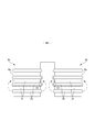
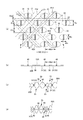
- the elastic sheet 30 is interposed between the first sheet layer 20A and the second sheet layer 20B.
- the elasticity of the first sheet layer 20A and the second sheet layer 20B being joined through a joint hole 31 penetrating the elastic sheet 30 at a large number of joints 40 arranged at intervals. It has a sheet elastic structure 20X. That is, the outer peripheral edge of the joint portion 40 is surrounded by the inner peripheral edge of the joint hole 31, and the two are not joined and can be separated from each other.
- first sheet layer 20A and the second sheet layer 20B may be joined via the elastic sheet 30 by a large number of joints 40 arranged at intervals.
- the region having the elastic sheet expansion / contraction structure 20X is contracted in the width direction due to the contraction of the elastic sheet 30 and can be expanded in the width direction WD (that is, the expansion / contraction direction ED becomes the width direction WD of the diaper).
- the waist elastic member 24 is an elongated elastic member such as a plurality of elastic threads arranged at intervals in the front-rear direction LD, and gives an elastic force so as to tighten around the waist of the body.
- the waist elastic members 24 are not arranged as a bundle with close intervals, but are arranged at intervals of about 3 to 8 mm in the front-rear direction so as to form a predetermined expansion / contraction zone. Preferably, 5 or more are arranged.
- the elongation rate at the time of fixing the waist elastic member 24 can be appropriately determined, but in the case of a normal adult, it can be about 230 to 320%.
- thread rubber is used in the illustrated example, but other elongated elastic members such as flat rubber may be used.
- an elastic sheet 30 may be provided at the waist end 23, and an elongated waist elastic member 24 may be provided at a position overlapping the elastic sheet 30 to form an elastic structure composed of both elastic members.
- the leg tube portion 50 has an elastic sheet telescopic structure 20X.
- the elastic sheet telescopic structure 20X can be formed by separate members in the leg tube portion 50 and other parts, but from the viewpoint of ease of manufacture and the like, the exterior body 20 is as shown in the illustrated example. It is preferable that the region from the leg tube portion 50 to at least one of the front and rear waist circumference portions is a region having a single elastic sheet telescopic structure 20X. Further, the leg tube portion 50 is not provided with an elastic member other than the elastic sheet 30 such as an elongated elastic member extending along the leg opening LO because of the formation of the convex region 55 and the concave region 57, which will be described later.
- the elastic sheet expansion / contraction structure 20X is not provided in the portion other than the waist end portion 23 in the waist circumference portion, but the expansion / contraction structure by the conventional elongated waist elastic member 26 such as thread rubber is provided. You can also.
- the region of the exterior body 20 having the elastic sheet elastic structure 20X has an elastic region 80 that can be expanded and contracted in the width direction WD.
- the elastic sheet 30 contracts in the width direction WD due to the contraction force of the elastic sheet 30, and can expand in the width direction WD. More specifically, in a state where the elastic sheet 30 is extended in the width direction WD, the elastic sheet 30 is separated from each other in the width direction WD and the front-rear direction LD (direction LD orthogonal to the expansion / contraction direction) orthogonal to the width direction WD.
- the elastic sheet elastic structure 20X is formed by joining the first sheet layer 20A and the second sheet layer 20B through the joint hole 31 to form a large number of joint portions 40, and the elastic sheet 30 is formed in the elastic region 80.
- the joint 40 By arranging the joint 40 so that the first sheet layer 20A and the second sheet layer 20B are contracted by the contraction force of the elastic sheet 30 to form the contraction folds 25 while remaining uninterrupted in the width direction WD. , Such elasticity can be imparted.
- the first sheet layer 20A and the second sheet layer 20B between the joints 40 are opposite to each other (so that they are separated from each other).
- the contraction folds 25 that swell and extend in the anteroposterior direction LD are formed, and even in the wearing state that extends to some extent in the width direction WD, the contraction folds 25 are extended but remain.
- the first sheet layer 20A and the second sheet layer 20B are not joined to the elastic sheet 30 except between the first sheet layer 20A and the second sheet layer 20B at least in the joint portion 40.
- FIG. 13 (c) assuming a mounted state and FIG.
- the elastic sheet 30 Even if the edge of the joint hole 31 is separated from the outer peripheral edge of the joint portion 40 in the expansion / contraction direction and the ventilation hole 33 (gap) is opened, and the material of the elastic sheet 30 is a non-perforated film or sheet, the ventilation hole 33 Adds breathability.
- the elastic sheet 30 has a portion 32 linearly continuous along the width direction WD, in the natural length state, the joint hole 31 is narrowed due to further contraction of the elastic sheet 30, and the joint hole 31 is narrowed. A gap is hardly formed between the 31 and the joint portion 40, and when the elastic sheet 30 does not have a linearly continuous portion along the width direction WD, the ventilation hole 33 remains.
- the maximum elongation of the WD in the width direction of the expansion / contraction region 80 is 190% or more (preferably 200 to 220%).
- the maximum elongation of the expansion / contraction region 80 is substantially determined by the elongation rate of the elastic sheet 30 at the time of manufacture, but based on this, it decreases due to a factor that inhibits the contraction of the WD in the width direction.
- the main factor of such an inhibitory factor is the ratio of the length of the joint portion 40 to the unit length in the width direction WD, and the larger the ratio, the lower the maximum elongation. In a normal case, since the length of the joint portion 40 correlates with the area ratio of the joint portion 40, the maximum elongation of the expansion / contraction region 80 can be adjusted by the area ratio of the joint portion 40.
- the elongation stress of the expansion / contraction region 80 is mainly the width of the elastic sheet 30 when the elastic sheet 30 has a portion 32 linearly continuous along the width direction WD as shown in the example shown in FIG. It can be adjusted by the sum of the orthogonal dimensions 32w of the portions 32 (see FIG. 13A) that are linearly continuous along the direction WD (equal to the spacing 31d of the orthogonal directions XD of the joint holes).
- the elastic sheet 30 does not have a linearly continuous portion along the width direction WD as in the example shown in FIG. 11 and the example shown in FIG. 15, the elongation stress of the expansion / contraction region 80 is increased.
- the area ratio of the joint portion 40 and the area of each joint portion 40 in the expansion / contraction region 80 can be appropriately determined, but usually, it is preferably within the following range.
- Area of joint 40 0.14 to 3.5 mm 2 (particularly 0.14 to 1.0 mm 2 )
- Area ratio of joint 40 1.8 to 19.1% (especially 1.8 to 10.6%)
- the maximum elongation and elongation stress of the expansion / contraction region 80 can be adjusted by the area ratio and the interval of the joint portion 40, as shown in FIG. 2, a plurality of joint portions 40 having different area ratios and intervals in the expansion / contraction region 80. Area can be provided.
- the distance between the joints 40 is not particularly limited, but for example, the distance 40d in the expansion / contraction direction can be about 0.5 to 5 times the maximum width 40x of the joint 40 and about 0.5 to 2 mm in length.
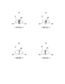
- the shapes of the individual joints 40 and the joint holes 31 in the natural length state can be appropriately determined, such as a perfect circle, an ellipse, a triangle, a rectangle (see FIG. 13), and a rhombus (see FIG. 14 (b)). It can be any shape such as a polygonal shape, a convex lens shape (see FIG. 14 (a)), a concave lens shape (see FIG. 14 (c)), a star shape, and a cloud shape.
- the dimensions of the individual joints are not particularly limited, but the maximum length 40y (approximately equal to the dimension 31y in the orthogonal direction of the joint hole 31) is 0.5 to 3.0 mm, particularly 0.7 to 1.1 mm.
- the maximum width of 40x is preferably 0.1 to 3.0 mm, and particularly preferably 0.1 to 1.1 mm in the case of a shape long in the direction XD orthogonal to the expansion / contraction direction.
- Reference numeral 40e indicates the center distance of the joint portion 40 in the orthogonal direction XD
- reference numeral 40f indicates the center distance of the joint portion 40 in the expansion / contraction direction ED.
- reference numeral 31x indicates the dimension of the expansion / contraction direction ED of the joint hole
- reference numeral 31e indicates the center distance of the orthogonal direction XD of the joint hole
- reference numeral 31f indicates the center distance of the expansion / contraction direction ED of the joint hole 31. ..
- the arrangement pattern of the joint portion 40 of the expansion / contraction region 80 is not particularly limited, and any pattern (see, for example, Patent Documents 1 to 8) can be adopted, and in particular, the example shown in FIG. 13 and the example shown in FIG. As described above, it is preferable that the non-joint zone in which the portions having no joint portion are continuous exists in an oblique lattice pattern.
- Non-stretchable area As shown in FIG. 2, of the region of the exterior body 20 having the elastic sheet elastic structure 20X, a part or all of the portion overlapping the absorber 13 (preferably including almost the entire inner / outer fixed region 10B) is desired.
- a non-stretchable region 70 can be provided at the site of.
- the non-stretchable region 70 When the non-stretchable region 70 is provided in the portion overlapping the absorber 13, its arrangement can be appropriately determined.
- the non-stretchable region 70 may be provided from the region overlapping the absorber 13 to the region not overlapping the absorber 13 located in the width direction WD or the front-rear direction LD.
- the non-stretchable region 70 means that the maximum stretch in the stretch direction is 120% or less.
- the maximum elongation of the non-stretchable region 70 is preferably 110% or less, and more preferably 100%.
- the shape of the individual joints 40 in the non-stretchable region 70 is not particularly limited, and can be appropriately selected from the same shapes as those described in the section of the stretchable region 80.
- the area ratio of the joint portion 40 and the area of each joint portion 40 in the non-stretchable region can be appropriately determined, but in the normal case, the area of each joint portion 40 is small and the joint portion is within the following range. It is preferable that the non-stretchable region 70 does not become hard due to the low area ratio of 40.
- Area of joint 40 0.10 to 0.75 mm 2 (particularly 0.10 to 0.35 mm 2 )
- Area ratio of joint 40 4 to 13% (especially 5 to 10%)
- the non-stretchable region 70 can be formed by densely arranging the joints 40 so that the first sheet layer 20A and the second sheet layer 20B do not shrink due to the contraction force of the elastic sheet 30 to form folds. ..
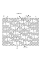
- Specific examples of the method for forming the non-stretchable region 70 include those described in Patent Document 3. 16 and 17 show an example of the non-stretchable region 70 described in Patent Document 3.
- the joint holes 31 are arranged in a staggered pattern in a dense arrangement to some extent, and the elastic sheet 30 is continuous with the expansion / contraction direction ED, but due to the presence of the joint holes 31, the joint holes 31 are linearly arranged along the expansion / contraction direction ED. It does not have a continuous part.
- the ventilation holes 33 (gap) are opened with a size that is almost the same in both the natural length state and the unfolded state.
- the joining means of the first sheet layer 20A and the second sheet layer 20B at the joining portion 40 is not particularly limited.
- the first sheet layer 20A and the second sheet layer 20B at the joining portion 40 may be joined by a hot melt adhesive or by joining means such as heat sealing or ultrasonic sealing.
- the form in which the joining portion 40 is formed by material welding is the first sheet layer in the joining portion 40.
- a first welded form in which the first sheet layer 20A and the second sheet layer 20B are joined only by a molten solidified product 20m of at least one of 20A and the second sheet layer 20B see FIG. 18A.
- a second welded form in which the first sheet layer 20A and the second sheet layer 20B are joined only by the molten solidified product 30 m of all or most or part of the elastic sheet 30 at the joint portion 40 see FIG. 18B.
- any of the third welded forms in which both of these are combined see FIG. 18C), but the second and third welded forms are preferable.
- the first sheet layer 20A due to the melted solidified 20 m of a part of the first sheet layer 20A and the second sheet layer 20B and the melted solidified product 30 m of all or most of the elastic sheet 30 at the joint portion 40. And the second sheet layer 20B are joined.
- the molten solidified product 30 m of the elastic sheet 30 can be seen between the molten solidified products 20 m of the fibers of the first sheet layer 20A or the second sheet layer 20B.
- the molten solidified product of the elastic sheet 30 is not seen between the molten solidified products 20 m of the fibers of the first sheet layer 20A or the second sheet layer 20B.
- the core (composite) of all the fibers of the joint portion 40 is such that a part of the first sheet layer 20A and the second sheet layer 20B does not melt. Not only the core of the fiber but also the central part of the single component fiber remains), but the peripheral part (including not only the sheath of the composite fiber but also the surface layer side part of the single component fiber) remains in a melted form or some fibers. Contains a form in which all the remaining fibers are melted or the core remains but the surrounding part is melted, although it does not melt at all.
- the molten solidified product 30 m of the elastic sheet 30 is the joint portion 40 as shown in FIG. 19 (c).
- the first sheet layer 20A and the second sheet layer 20B may permeate between the fibers over the entire thickness direction, but as shown in FIG. 19A, the form permeates between the fibers to the middle in the thickness direction, or the figure.
- the flexibility of the joint portion 40 is higher in the form in which the fibers of the first sheet layer 20A and the second sheet layer 20B hardly permeate.
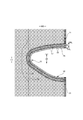
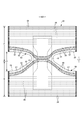
- convex regions 55 and concave regions 57 are alternately and repeatedly provided in the leg tube portion 50 while being adjacent to each other in the leg length direction orthogonal to the circumferential direction.
- the circumferential direction of the leg tube portion 50 is a direction parallel to the edge 29 of the leg opening.
- the leg length direction is the front-rear direction LD at the end portion on the side seal portion 21 side, and the width direction WD at the narrowest portion of the exterior body 20.
- the convex region 55 and the concave region 57 are elastic regions 80 having an elastic sheet elastic structure 20X.
- the first sheet layer 20A and the second sheet layer 20B in each region have folds 25 formed by swelling in opposite directions while contracting in the expansion / contraction direction together with the elastic sheet 30.
- it has folds 25 (see FIG. 13C) formed by contracting together with the elastic sheet 30 in the expansion / contraction direction (width direction WD in the example shown in FIG. 2).
- the interval 40d of the expansion / contraction direction ED of the joint portion 40 is wider than in the concave region 57
- the convex region 55 and the concave region 57 are regions in which the dimensions 55L and 57L in the leg length direction are constant, respectively.
- the dimension 55L in the leg length direction of the convex region 55 is equal to or less than the dimension 57L in the leg length direction of the concave region 57.
- a fold 25 higher and larger than the concave region 57 is formed in the convex region 55. Therefore, as shown in FIG. 10, one of the convex region 55 and the concave region 57 is relatively convex and the other is relatively concave due to the difference in thickness (difference in maximum elongation) due to the folds 25 in the contracted state. It is a thing.
- the elastic sheet expansion / contraction structure 20X can be formed by separate members in the convex region 55 and the concave region 57.
- the leg length is provided. This is preferable because the elasticity of the leg tube portion 50 is not interrupted in the longitudinal direction and the fit of the leg tube portion 50 is improved.
- the elastic sheet 30 may not be provided in the convex region 55, and the joint portion 40 may not be provided. ..
- the narrow elastic sheet 30 forming the concave region 57 is directed from one side seal portion 21 toward the center of the width direction WD along the edge 29 of the leg opening, and is in the width direction.
- a plurality of pieces may be mounted in parallel in a pattern that crosses the center of the WD toward the other leg opening LO and reaches the other side seal portion 21 along the edge 29 of the other leg opening.
- the expansion / contraction direction is the attachment direction of the elastic sheet 30, and therefore, the expansion / contraction direction is the circumferential direction of the leg tube portion 50 at the portion where the attachment direction of the elastic sheet 30 is along the edge 29 of the leg opening.
- the convex region 55 and the concave region 57 preferably form a continuous ring shape in the circumferential direction of the leg tube portion 50, but may be provided intermittently in the circumferential direction as shown in FIG.
- the convex region 55 and the concave region 57 are provided only outside the WD in the width direction from the narrowest portion of the exterior body 20 (the expansion / contraction region 80 is provided), but the illustration is limited to this. However, there may be a portion where the convex region 55 and the concave region 57 are not provided on the outer side of the width direction WD than the narrowest portion of the exterior body 20.
- the convex region 55 and the concave region 57 are alternately and repeatedly provided while being adjacent to each other in the leg length direction, and when the leg tube portion 50 is turned over and overlapped in a double manner or the like, the convex region 55 and the concave region 57 are squeezed.
- convex regions 55 and concave regions 57 can be alternately and repeatedly provided in the circumferential direction at the same position in the leg length direction (that is, the convex regions 55 and concave regions 57 have a checkered pattern). Become). In this case, the rolled-up portion of the leg tube portion 50 is difficult to move in the circumferential direction, but the tightening force in the circumferential direction changes.
- the dimension 55L in the leg length direction of the convex region 55 can be appropriately determined as long as it is equal to or less than the dimension 57L in the leg length direction of the concave region 57, but the dimension 55L in the leg length direction of the convex region 55 is the dimension 55L of the concave region 57. It is preferably smaller than the dimension 57L in the leg length direction. Further, specific dimensions can be appropriately determined. For example, in a normal case, the dimension 55L in the leg length direction of the convex region 55 can be about 5 to 10 mm, and the dimension 57L in the leg length direction of the concave region 57 can be set. It can be about 3 to 8 mm.
- the maximum elongation of the convex region 55 and the concave region 57 may be appropriately adjusted according to the degree of engagement desired for the convex region 55 and the concave region 57, but in a normal case, the maximum elongation direction of the convex region 55 is maximum. It is preferable that the elongation is 200 to 350% and the maximum elongation in the expansion / contraction direction of the concave region 57 is 0.70 to 0.95 times the maximum elongation in the expansion / contraction direction of the convex region 55.
- the presser sheet 60 is used to cover the front and rear ends of the interior body 10 mounted on the inner surface of the exterior body 20 and to prevent leakage from the front and rear edges of the interior body 10. May be provided.
- the presser sheet 60 extends over the entire width direction from the inner surface of the folded portion 20C of the inner surface of the front body F to the position where it overlaps with the front end portion of the interior body 10, and the inner surface of the rear body B.
- the folded portion 20C extends from the inner surface to a position overlapping the rear end portion of the interior body 10 over the entire width direction.
- the folded-back portion 20C can be extended to a portion overlapping the interior body 10 to form a portion equivalent to the pressing sheet 60.
- the non-woven fabric in the above description a known non-woven fabric can be appropriately used depending on the site and purpose.
- the constituent fibers of the non-woven fabric include olefin-based fibers such as polyethylene and polypropylene, polyester-based and polyamide-based synthetic fibers (including single-component fibers and composite fibers such as core sheaths), as well as recycled rayon and cupra. Fibers, natural fibers such as cotton, and the like can be selected without particular limitation, and these can be mixed and used. In order to increase the flexibility of the non-woven fabric, it is preferable that the constituent fibers are crimped fibers.
- the constituent fibers of the non-woven fabric are hydrophobic fibers or water-repellent fibers (water-repellent fibers made water-repellent by the water-repellent agent) even if they are hydrophilic fibers (including those made hydrophilic by the hydrophilic agent).
- the non-woven fabric generally has a short fiber non-woven fabric, a long fiber non-woven fabric, a spunbond non-woven fabric, a melt blown non-woven fabric, a spunlace non-woven fabric, a thermal bond (air-through) non-woven fabric, and a needle punch depending on the fiber length, the sheet forming method, the fiber bonding method, and the laminated structure.
- non-woven fabrics It is classified into non-woven fabrics, point-bonded non-woven fabrics, laminated non-woven fabrics (SMS non-woven fabrics having a melt blown layer sandwiched between spunbond layers, SMMS non-woven fabrics, etc.), and any of these non-woven fabrics can be used.
- SMS non-woven fabrics having a melt blown layer sandwiched between spunbond layers, SMMS non-woven fabrics, etc.
- the "front-back direction” means the direction indicated by the symbol LD in the figure (vertical direction), and the “width direction” means the direction indicated by the WD in the figure (horizontal direction), and the front-back direction and the width direction. Are orthogonal.
- -"MD direction” and “CD direction” mean the flow direction (MD direction) in the manufacturing equipment and the lateral direction (CD direction) orthogonal to this, and one of them is the front-back direction depending on the part of the product. And the other is in the width direction.
- the MD direction of the non-woven fabric is the direction of fiber orientation of the non-woven fabric.
- the "front surface” means the surface of the member that is closer to the wearer's skin when worn, and the “back surface” means the surface of the member that is farther from the wearer's skin when worn.
- .. -"Front body” and “rear body” mean the front and rear parts of the disposable diaper with the center in the front-rear direction as the boundary, respectively.
- “Crotch portion” means a portion that is located in the crotch of the wearer, and normally, as shown in FIG. 14, the tangent line and the front and back of the edge 29 of the leg opening in the unfolded state including the center in the front-back direction. It means a range in the front-rear direction in which the acute-angled intersection angle with the direction is 45 ° or less.
- Maximum elongation means the maximum value of elongation in the expansion / contraction direction ED (in other words, elongation in the expanded state in which the first sheet layer and the second sheet layer are expanded flat without shrinkage or slack), and is in the expanded state.
- the length is expressed as a percentage when the natural length is 100%.
- Area ratio means the ratio of the target portion to the unit area, and the target portion (for example, the joint portion 40, the opening of the joint hole 31, the ventilation hole) in the target region (for example, the stretchable region 80 and the non-stretchable region 70).
- the total area of the above is divided by the area of the target area and expressed as a percentage.
- the "area ratio" in the region having a stretchable structure means the area ratio in the expanded state. In a form in which a large number of target portions are provided at intervals, it is desirable to set the target area to a size that includes 10 or more target portions and obtain the area ratio.
- Elongation rate means the value when the natural length is 100%. For example, an elongation rate of 200% is synonymous with an elongation ratio of 2 times.
- Methodsuke is measured as follows. After pre-drying the sample or test piece, leave it in a test room or device under standard conditions (test location: temperature 23 ⁇ 1 ° C., relative humidity 50 ⁇ 2%) to bring it to a constant weight. Pre-drying refers to constant weight of a sample or test piece in an environment at a temperature of 100 ° C. It is not necessary to pre-dry the fibers having an official moisture content of 0.0%. From the test piece in a constant amount, a sample having a size of 100 mm / 100 mm is cut out using a sampling template (100 mm / 100 mm). The weight of the sample is measured and multiplied by 100 to calculate the weight per square meter, which is used as the basis weight.
- the "thickness" of the absorber is the thickness measuring instrument of Ozaki Seisakusho Co., Ltd. (peacock, dial thickness gauge large type, model JB (measurement range 0 to 35 mm) or model K-4 (measurement range 0 to 50 mm)) Measure with the sample and the thickness measuring device horizontal.
- the "thickness” other than the above is automatically measured using an automatic thickness measuring device (KES-G5 handy compression measurement program) under the conditions of a load of 0.098 N / cm 2 and a pressurized area of 2 cm 2.
- the direction of "fiber orientation of the non-woven fabric” is the direction along which the fibers of the non-woven fabric follow. It can be discriminated by a simple measuring method in which the fiber orientation direction is determined from the tensile strength ratio in the direction.
- Unfolded state means a state in which it is unfolded flat without shrinkage or slack.
- the dimensions and positional relationship of each part mean the dimensions in the unfolded state, not in the natural length state.
- test or measurement shall be performed in a test room or equipment under standard conditions (test location: temperature 23 ⁇ 1 ° C, relative humidity 50 ⁇ 2%). do.
- the present invention can be used for trunks type disposable diapers as in the above example.
- Elastic sheet elastic structure 21 ... Side seal part, 22 ... Intermediate area, 24 ... Waist elastic member, 25 ... Folds, 26 ... Elastic member around the waist, 28 ... Crotch part, 29 ... Edge of leg opening, 30 ... Elastic sheet, 40 ... Joint part, 50 ... Leg tube part, 51 ... Inner thigh contact part, 55 ... Convex area, 57 ... concave area, 60 ... presser sheet, 70 ... non-stretchable area, 80 ... stretchable area.
Landscapes
- Health & Medical Sciences (AREA)
- Epidemiology (AREA)
- Engineering & Computer Science (AREA)
- Biomedical Technology (AREA)
- Heart & Thoracic Surgery (AREA)
- Vascular Medicine (AREA)
- Life Sciences & Earth Sciences (AREA)
- Animal Behavior & Ethology (AREA)
- General Health & Medical Sciences (AREA)
- Public Health (AREA)
- Veterinary Medicine (AREA)
- Absorbent Articles And Supports Therefor (AREA)
Applications Claiming Priority (2)
| Application Number | Priority Date | Filing Date | Title |
|---|---|---|---|
| JP2020057842A JP7289276B2 (ja) | 2020-03-27 | 2020-03-27 | トランクスタイプ使い捨て着用物品 |
| JP2020-057842 | 2020-03-27 |
Publications (1)
| Publication Number | Publication Date |
|---|---|
| WO2021193152A1 true WO2021193152A1 (ja) | 2021-09-30 |
Family
ID=77892035
Family Applications (1)
| Application Number | Title | Priority Date | Filing Date |
|---|---|---|---|
| PCT/JP2021/010130 Ceased WO2021193152A1 (ja) | 2020-03-27 | 2021-03-12 | トランクスタイプ使い捨て着用物品 |
Country Status (3)
| Country | Link |
|---|---|
| JP (1) | JP7289276B2 (enExample) |
| TW (1) | TWI849300B (enExample) |
| WO (1) | WO2021193152A1 (enExample) |
Citations (3)
| Publication number | Priority date | Publication date | Assignee | Title |
|---|---|---|---|---|
| JP2008099865A (ja) * | 2006-10-19 | 2008-05-01 | Oji Nepia Kk | パンツ型使い捨ておむつ |
| JP2016187435A (ja) * | 2015-03-30 | 2016-11-04 | 王子ホールディングス株式会社 | ボクサーパンツ型使い捨ておむつ及び吸収性物品 |
| WO2018230184A1 (ja) * | 2017-06-13 | 2018-12-20 | 大王製紙株式会社 | パンツタイプ使い捨ておむつ |
Family Cites Families (1)
| Publication number | Priority date | Publication date | Assignee | Title |
|---|---|---|---|---|
| WO2018092541A1 (ja) * | 2016-11-15 | 2018-05-24 | 花王株式会社 | 吸収性物品 |
-
2020
- 2020-03-27 JP JP2020057842A patent/JP7289276B2/ja active Active
-
2021
- 2021-03-12 WO PCT/JP2021/010130 patent/WO2021193152A1/ja not_active Ceased
- 2021-03-23 TW TW110110302A patent/TWI849300B/zh active
Patent Citations (3)
| Publication number | Priority date | Publication date | Assignee | Title |
|---|---|---|---|---|
| JP2008099865A (ja) * | 2006-10-19 | 2008-05-01 | Oji Nepia Kk | パンツ型使い捨ておむつ |
| JP2016187435A (ja) * | 2015-03-30 | 2016-11-04 | 王子ホールディングス株式会社 | ボクサーパンツ型使い捨ておむつ及び吸収性物品 |
| WO2018230184A1 (ja) * | 2017-06-13 | 2018-12-20 | 大王製紙株式会社 | パンツタイプ使い捨ておむつ |
Also Published As
| Publication number | Publication date |
|---|---|
| JP2021153898A (ja) | 2021-10-07 |
| JP7289276B2 (ja) | 2023-06-09 |
| TW202139950A (zh) | 2021-11-01 |
| TWI849300B (zh) | 2024-07-21 |
Similar Documents
| Publication | Publication Date | Title |
|---|---|---|
| CN110868976B (zh) | 伸缩部件和具有该伸缩部件的一次性穿着物品 | |
| CN110868978B (zh) | 伸缩部件和具有该伸缩部件的一次性穿着物品 | |
| JP6240701B2 (ja) | パンツタイプ使い捨ておむつ | |
| WO2017163754A1 (ja) | 弾性フィルム伸縮構造の形成方法及び吸収性物品 | |
| JP6359071B2 (ja) | トランクスタイプ使い捨ておむつ | |
| JP2017176494A5 (enExample) | ||
| JP2018083019A5 (enExample) | ||
| JP6823491B2 (ja) | トランクスタイプ使い捨ておむつ | |
| JP2018134272A5 (enExample) | ||
| JP6359072B2 (ja) | トランクスタイプ使い捨ておむつ | |
| JP2018083021A5 (enExample) | ||
| JP6861505B2 (ja) | トランクスタイプ使い捨ておむつ | |
| JP7256775B2 (ja) | 使い捨て着用物品 | |
| JP6681866B2 (ja) | 伸縮部材及びこの伸縮部材を有するパンツタイプ使い捨て着用物品 | |
| WO2023026560A1 (ja) | パンツタイプ使い捨て着用物品 | |
| JP2018083023A5 (enExample) | ||
| JP7289276B2 (ja) | トランクスタイプ使い捨て着用物品 | |
| KR102519499B1 (ko) | 신축 부재 및 이 신축 부재를 갖는 일회용 착용 물품 | |
| JP6492208B2 (ja) | トランクスタイプ使い捨ておむつ | |
| JP2018083020A5 (enExample) | ||
| JP2018083020A (ja) | パンツタイプ使い捨ておむつ | |
| JP6492209B2 (ja) | トランクスタイプ使い捨ておむつ | |
| JP6752696B2 (ja) | トランクスタイプ使い捨ておむつ | |
| JP2019166217A (ja) | 使い捨て着用物品 | |
| JP2021153898A5 (enExample) |
Legal Events
| Date | Code | Title | Description |
|---|---|---|---|
| 121 | Ep: the epo has been informed by wipo that ep was designated in this application |
Ref document number: 21775888 Country of ref document: EP Kind code of ref document: A1 |
|
| NENP | Non-entry into the national phase |
Ref country code: DE |
|
| 122 | Ep: pct application non-entry in european phase |
Ref document number: 21775888 Country of ref document: EP Kind code of ref document: A1 |