WO2021193152A1 - Trunks-type disposable article - Google Patents
Trunks-type disposable article Download PDFInfo
- Publication number
- WO2021193152A1 WO2021193152A1 PCT/JP2021/010130 JP2021010130W WO2021193152A1 WO 2021193152 A1 WO2021193152 A1 WO 2021193152A1 JP 2021010130 W JP2021010130 W JP 2021010130W WO 2021193152 A1 WO2021193152 A1 WO 2021193152A1
- Authority
- WO
- WIPO (PCT)
- Prior art keywords
- region
- sheet layer
- sheet
- leg
- convex
- Prior art date
Links
Images


Classifications
-
- A—HUMAN NECESSITIES
- A61—MEDICAL OR VETERINARY SCIENCE; HYGIENE
- A61F—FILTERS IMPLANTABLE INTO BLOOD VESSELS; PROSTHESES; DEVICES PROVIDING PATENCY TO, OR PREVENTING COLLAPSING OF, TUBULAR STRUCTURES OF THE BODY, e.g. STENTS; ORTHOPAEDIC, NURSING OR CONTRACEPTIVE DEVICES; FOMENTATION; TREATMENT OR PROTECTION OF EYES OR EARS; BANDAGES, DRESSINGS OR ABSORBENT PADS; FIRST-AID KITS
- A61F13/00—Bandages or dressings; Absorbent pads
- A61F13/15—Absorbent pads, e.g. sanitary towels, swabs or tampons for external or internal application to the body; Supporting or fastening means therefor; Tampon applicators
- A61F13/45—Absorbent pads, e.g. sanitary towels, swabs or tampons for external or internal application to the body; Supporting or fastening means therefor; Tampon applicators characterised by the shape
- A61F13/49—Absorbent articles specially adapted to be worn around the waist, e.g. diapers
- A61F13/496—Absorbent articles specially adapted to be worn around the waist, e.g. diapers in the form of pants or briefs
-
- A—HUMAN NECESSITIES
- A61—MEDICAL OR VETERINARY SCIENCE; HYGIENE
- A61F—FILTERS IMPLANTABLE INTO BLOOD VESSELS; PROSTHESES; DEVICES PROVIDING PATENCY TO, OR PREVENTING COLLAPSING OF, TUBULAR STRUCTURES OF THE BODY, e.g. STENTS; ORTHOPAEDIC, NURSING OR CONTRACEPTIVE DEVICES; FOMENTATION; TREATMENT OR PROTECTION OF EYES OR EARS; BANDAGES, DRESSINGS OR ABSORBENT PADS; FIRST-AID KITS
- A61F13/00—Bandages or dressings; Absorbent pads
- A61F13/15—Absorbent pads, e.g. sanitary towels, swabs or tampons for external or internal application to the body; Supporting or fastening means therefor; Tampon applicators
- A61F13/51—Absorbent pads, e.g. sanitary towels, swabs or tampons for external or internal application to the body; Supporting or fastening means therefor; Tampon applicators characterised by the outer layers
Definitions
- the present invention relates to a trunks type disposable wear article in which the fit of the leg tube portion can be changed.
- Pants-type disposable diapers have a waist opening and a pair of leg openings, an exterior that extends from the edge of the front waist opening to the edge of the rear waist opening, and an absorber provided at least in the crotch area of this exterior.
- a structure having an interior body including the above and side seal portions for joining both front side portions and rear side side portions of the exterior body is common.
- trunks-type (also called one-quarter length or boxer-type) disposable diapers having a pair of leg cylinders surrounding the base side of the thigh are also known (for example, Patent Document 1, Patent Document 1, 2).
- an elastic member In trunks type disposable diapers, by attaching an elastic member to the leg tube, an elastic region that elastically expands and contracts in the circumferential direction is provided in the leg tube.
- an elongated elastic member such as rubber thread is generally used as the elastic member attached to the leg tube portion.
- the present inventor increases the number of elastic members per unit contact area of the leg tube portion by turning over the leg tube portion as necessary and stacking the leg tube portions in a double layer or the like. Therefore, it was found that the tightening pressure can be increased.
- the main object of the present invention is to suppress an increase in thickness when the elastic leg tube portion is turned over.
- the trunks type disposable wear items that have solved the above problems are as follows. ⁇ First aspect> It has a pair of leg tubes that surround the base of the thigh. Convex regions and concave regions are alternately and repeatedly provided in the leg tube portion while being adjacent to each other in the leg length direction orthogonal to the circumferential direction.
- the convex region and the concave region are regions in which the first sheet layer and the second sheet layer are overlapped.
- the convex region has a joint portion between the first sheet layer and the second sheet layer, which is not joined to the first sheet layer and the second sheet layer, or is provided at intervals.
- the concave region has a joint portion between the first sheet layer and the second sheet layer provided at intervals.
- An elastic sheet is provided between the first sheet layer and the second sheet layer at least in the concave region.
- the first sheet layer and the second sheet layer in the convex region and the concave region have folds formed by expanding in opposite directions while contracting in the expansion / contraction direction together with the elastic sheet.
- the distance between the joints in the expansion and contraction direction is wider than that in the concave region.
- the convex region and the concave region have constant dimensions in the leg length direction, respectively.
- the dimension of the convex region in the leg length direction is equal to or less than the dimension of the concave region in the leg length direction. Trunks type disposable wear goods characterized by that.
- convex regions and concave regions are alternately and repeatedly provided adjacent to each other in the leg length direction.
- at least the concave region has an elastic sheet, and the first sheet layer and the second sheet layer in the convex region and the concave region are opposite to each other while contracting in the expansion / contraction direction together with the elastic sheet in the natural length and the state of being contracted to some extent. It has folds that bulge in the direction. Even if the convex region alone does not expand or contract from the concave region (including the case where it does not have an elastic member such as an elastic sheet), it contracts together with the adjacent concave region to form folds.
- the convex region has a wider distance in the expansion / contraction direction of the joint than the concave region, the convex region is higher than the concave region at least in the mounted state (for example, in the state of extending to half of the maximum elongation in the expansion / contraction direction). Large folds will be formed. Therefore, one of the convex region and the concave region is relatively convex and the other is relatively concave due to the difference in thickness (difference in maximum elongation) due to the folds in the contracted state.
- the convex region and the concave region can be engaged with each other when the wearer turns the leg tube portion and overlaps the leg cylinder portion in a double manner or the like. Therefore, the tightening pressure can be increased while suppressing the increase in thickness.
- the meshing of the convex region and the concave region also brings an advantage that the rolled-up portion is less likely to shift.
- the elastic sheet is provided in the convex region and the concave region, and is provided in the convex region and the concave region.
- the arrangement pattern of the joint portion in the convex region and the arrangement pattern of the joint portion in the concave region are different.
- the trunks type disposable wear article of the first aspect is provided in the convex region and the concave region.
- the convex region is provided at the end of the leg tube portion on the leg opening side.
- the maximum elongation of the convex region in the expansion and contraction direction is 200 to 350%, and the maximum elongation of the concave region in the expansion and contraction direction is 0.70 to 0.95 times the maximum elongation of the convex region in the expansion and contraction direction.
- Trunks type disposable wear article of the second or third aspect Trunks type disposable wear article of the second or third aspect.
- the convex region and the concave region have an elastic sheet, one is convex and the other is concave due to the difference in maximum elongation. Therefore, the maximum elongation of the convex region and the concave region may be appropriately adjusted according to the degree of engagement desired in the convex region and the concave region, but it is usually preferable to be within the range of this embodiment.
- An exterior body having a waist opening and a pair of leg openings extending from the edge of the front waist opening to the edge of the rear waist opening, and an interior body including an absorber provided at least in the crotch portion of the exterior body. It has a side seal portion that joins both front side portions and rear side side portions of the exterior body. An annular waist circumference is formed between one side seal portion in the width direction and the other side seal portion in the exterior body.
- the crotch portion of the exterior body has a pair of inner thigh contact portions extending outward in the width direction from both side edges of the absorber, and a portion along the edge of the leg opening including these inner thigh contact portions. However, it is the leg tube part.
- a region extending from the leg tube portion to at least one of the front and rear waist circumference portions is a region having the first sheet layer, the second sheet layer, and the elastic sheet.
- the trunks type disposable wear article having the same basic structure as the pants type disposable wear article without the leg tube portion as in this embodiment, the first sheet layer and the second sheet layer common from the waist circumference to the leg tube portion. It is preferable because the sheet layer and the elastic sheet can be arranged to add elasticity.
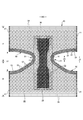
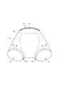
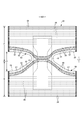
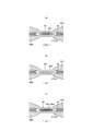
- FIG. 3 is a cross-sectional view taken along the line 3-3 of FIG. It is a perspective view seen from the front diagonally lower side with the trunks type disposable diaper attached. It is a top view which shows the main part of the trunks type disposable diaper in an expanded state in an enlarged manner.
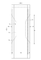
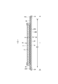
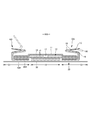
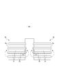
- FIG. 1 It is a top view which shows the main part of the trunks type disposable diaper in an expanded state in an enlarged manner. It is a front schematic diagram for demonstrating the usage method. It is a top view which shows the main part of the trunks type disposable diaper in an expanded state in an enlarged manner. It is a plan view (outer surface side) of a trunks type disposable diaper in an unfolded state.
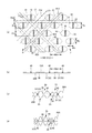
- A is a plan view of a main part of the stretchable region in the expanded state
- (b) is a cross-sectional view taken along the line DD of (a)
- (c) is a cross-sectional view taken in the mounted state
- (d) is a cross-sectional view taken in the natural length state. be.
- A is a plan view of a main part of a non-stretchable region
- (b) is a cross-sectional view taken along the line DD of (a)
- (c) is a cross-sectional view taken in a mounted state
- (d) is a cross-sectional view taken in a natural length state.
- It is a main part plan view of a non-stretchable region. It is sectional drawing which shows roughly the cross section of the main part of the exterior body extended to some extent.
- FIGS. 1 to 10 show trunks-type disposable diapers (hereinafter, also simply referred to as diapers) as an example of trunks-type disposable wear articles having a pair of leg cylinders 50.
- the hot melt adhesive can be applied by a known method such as slot coating, continuous linear or dotted bead coating, spiral or Z-shaped spray coating, or pattern coating (transfer of hot melt adhesive by letterpress method). Can be applied.
- a hot melt adhesive can be applied to the outer peripheral surface of the elastic member to fix the elastic member to the adjacent member.
- hot melt adhesive examples include EVA type, adhesive rubber type (elastomer type), olefin type, polyester / polyamide type and the like, but they can be used without particular limitation.
- a joining means for joining each component a means by material welding such as a heat seal or an ultrasonic seal can also be used.
- the pair of leg tube portions 50 of the trunks type disposable diaper is not particularly limited as long as it has a tubular shape surrounding the thigh in the worn state, and the structures described in Patent Documents 1 and 2 can be adopted.
- the trunks type disposable diaper shown in the illustrated example adopts a structure simpler than that described in Patent Documents 1 and 2.
- the trunks type disposable diaper of the illustrated example has a waist opening WO and a pair of leg openings LO, and an exterior body 20 extending from the edge of the waist opening WO of the front body F to the edge of the waist opening WO of the back body B.
- an interior body 10 including an absorber 13 provided at least in the crotch portion 28 of the exterior body 20, and side seal portions 21 for joining both front side portions and rear side side portions of the exterior body 20. It is a thing.
- the crotch portion 28 of the exterior body 20 has a pair of inner thigh contact portions 51 extending from both side edges of the absorber 13 to one side and the other side of the WD in the width direction, respectively, and these inner thigh contact portions 51 are provided.
- the portion along the edge 29 of the leg opening including the leg opening is a pair of leg tube portions 50 surrounding the base side of the thigh.
- a joining means such as a hot melt adhesive
- the interior body 10 and the exterior body 20 are the boundaries between the front body F and the back body B in the front-rear direction LD.
- a waist opening WO and a pair of leg openings LO are formed by folding at the center (vertical direction) and joining both side portions to each other by heat welding or hot melt adhesive to form a side seal portion 21. It becomes a trunks type disposable diaper.
- the interior body 10 has an absorber 13 interposed between the liquid-permeable top sheet 11 made of a non-woven fabric or the like and the liquid-impermeable sheet 12 made of polyethylene or the like. It has a structure and absorbs and retains the excrement liquid that has passed through the top sheet 11.
- the planar shape of the interior body 10 is not particularly limited, but it is generally a substantially rectangular shape as shown in the illustrated form.
- a perforated or non-perforated non-woven fabric, a perforated plastic sheet, or the like is preferably used.
- the material fibers constituting the non-woven fabric can be olefin-based fibers such as polyethylene or polypropylene, synthetic fibers such as polyester-based and polyamide-based, recycled fibers such as rayon and cupra, and natural fibers such as cotton.
- a non-woven fabric obtained by an appropriate processing method such as a spun bond method, a thermal bond method, a melt blown method, or a needle punch method can be used.
- the spunlace method is excellent in that it is rich in flexibility and drapeability, and the thermal bond method is excellent in that it is bulky and soft.
- the top sheet 11 involves the side edge portion of the absorber 13 and extends to the back surface side of the absorber 13, but is not limited to this.
- liquid-impermeable sheet 12 covering the back side of the absorber 13 a liquid-impermeable plastic sheet such as polyethylene or polypropylene is used, but in recent years, a liquid-impermeable sheet having moisture permeability is preferably used from the viewpoint of preventing stuffiness.
- the water-impervious / moisture-permeable sheet is a microporous sheet obtained by melting and kneading an inorganic filler in an olefin resin such as polyethylene or polypropylene to form a sheet, and then stretching the sheet in a uniaxial or biaxial direction. Can be mentioned.
- the liquid impermeable sheet 12 it is desirable to use an opaque sheet so that brown color such as defecation and urine does not appear.
- a plastic in which pigments such as calcium carbonate, titanium oxide, zinc oxide, white carbon, clay, talc, and barium sulfate and a filler are added and formed into a film is preferably used.
- the liquid impermeable sheet 12 is folded back on both sides in the width direction of the absorber 13 together with the top sheet 11, but the present invention is not limited to this.
- the absorber 13 is basically a known material, for example, a stack of pulp fibers, an aggregate of filaments such as cellulose acetate, or a non-woven fabric, and a highly absorbent polymer is mixed and fixed as necessary. Can be used.
- the absorber 13 can be packaged with a liquid-permeable and liquid-retaining packaging sheet 14 such as crepe paper, if necessary, in order to retain the shape and polymer.
- the overall shape of the absorber 13 is formed in a substantially hourglass shape having a constricted portion 13N narrower than both front and rear sides in the front-rear direction range including the crotch portion 28, but the overall shape should be an appropriate shape such as a rectangular shape. Can be done.
- the dimensions of the constricted portion 13N can be appropriately determined, but the length of the constricted portion 13N in the front-rear direction can be about 20 to 50% of the total length of the diaper, and the width of the narrowest portion 13 m is the total width 13 w of the absorber 13. It can be about 40 to 60% of.
- the portion of the interior body 10 corresponding to the constricted portion 13N of the absorber 13 does not have the absorber 13. A part is formed.
- the three-dimensional gather BS has a fixed portion fixed to the side portion of the back surface of the interior body 10, and the surface of the interior body 10 from this fixed portion via the side of the interior body 10.
- the main body portion extending to the side portion of the main body, the inverted portion formed by fixing the front and rear ends of the main body portion to the side portion of the surface of the interior body 10 in an inverted state, and the portion of this inverted portion are not fixed.
- the formed free portion is formed by a gather sheet 15 that is doubled by folding back.
- a non-woven fabric having water repellency is preferably used.
- an elongated gather elastic member 16 is arranged at the tip of a free portion or the like.
- the gather elastic member 16 is for forming a three-dimensional gather BS by erecting a free portion by an elastic elastic force as shown by a two-dot chain line in FIG. 5 in a product state.
- the gather elastic member 16 materials such as styrene rubber, olefin rubber, urethane rubber, ester rubber, polyurethane, polyethylene, polystyrene, styrene butadiene, silicone, and polyester, which are usually used, can be used. Further, in order to make it difficult to see from the outside, it is preferable to arrange the thickness at 925 dtex or less, the elongation rate at 150 to 350%, and the interval at 10.0 mm or less. As the gather elastic member 16, a tape-shaped member having a certain width can be used in addition to the thread-shaped member as shown in the illustrated figure.
- the non-woven fabric used for the gather sheet 15 is not particularly limited, and is made of olefin-based fibers such as polyethylene or polypropylene, synthetic fibers such as polyester-based and polyamide-based, recycled fibers such as rayon and cupra, and natural fibers such as cotton. It can also be produced by an appropriate processing method such as a spunbond method, a thermal bond method, a melt blown method, or a needle punch method.
- the exterior body 20 has a substantially hourglass shape in which the middle of the LD in the front-rear direction is constricted, and both side edges of the constriction are edges 29 of the leg openings, respectively.
- the crotch portion 28 of the exterior body 20 has a pair of inner thigh contact portions 51 extending from both side edges of the absorber 13 to one side and the other side of the WD in the width direction, respectively.
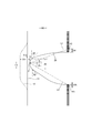
- the dimensions of the inner thigh contact portion 51 may be appropriately determined according to the length of the leg tube portion 50, but usually, the width 51x of the inner thigh contact portion 51 in the narrowest portion of the exterior body 20 is a diaper. It is preferably about 1 to 5% of the total length Y. Further, as shown in FIG. 9, in the front body F, the width direction is at an angle ⁇ 1 of 20 degrees with respect to the width direction from the virtual point P1 located on the edge 29 of the leg opening on the most width direction center side. When the virtual straight line L1 toward the outside and the waist side is drawn, it is preferable to have an intersection P2 between this virtual straight line L1 and the side edge of the exterior body 20 in the front-rear direction range having the side seal portion 21, and from this intersection P2.
- the distance between the front and rear directions 50f to the edge 29 of the leg opening is preferably 51d or more between the side edge of the exterior body 20 and the side edge of the interior body 10 in the narrowest portion of the exterior body 20, and is substantially the same. It is preferable to have.
- the virtual point P1 located on the edge 29 of the leg opening on the most central side in the width direction is virtual toward the outside and the waist side in the width direction at an angle ⁇ 2 of 30 degrees with respect to the width direction.
- the straight line L2 When the straight line L2 is drawn, it is preferable to have an intersection P3 between this virtual straight line L2 and the side edge of the exterior body 20 in the front-rear direction range having the side seal portion 21, and from this intersection P3 to the edge 29 of the leg opening.
- the distance between the front and rear directions 50b may be 51d or less or more than the distance between the side edge of the exterior body 20 and the side edge of the interior body 10 in the narrowest portion of the exterior body 20.
- the elastic sheet 30 is interposed between the first sheet layer 20A and the second sheet layer 20B.
- the elasticity of the first sheet layer 20A and the second sheet layer 20B being joined through a joint hole 31 penetrating the elastic sheet 30 at a large number of joints 40 arranged at intervals. It has a sheet elastic structure 20X. That is, the outer peripheral edge of the joint portion 40 is surrounded by the inner peripheral edge of the joint hole 31, and the two are not joined and can be separated from each other.
- first sheet layer 20A and the second sheet layer 20B may be joined via the elastic sheet 30 by a large number of joints 40 arranged at intervals.
- the region having the elastic sheet expansion / contraction structure 20X is contracted in the width direction due to the contraction of the elastic sheet 30 and can be expanded in the width direction WD (that is, the expansion / contraction direction ED becomes the width direction WD of the diaper).
- the waist elastic member 24 is an elongated elastic member such as a plurality of elastic threads arranged at intervals in the front-rear direction LD, and gives an elastic force so as to tighten around the waist of the body.
- the waist elastic members 24 are not arranged as a bundle with close intervals, but are arranged at intervals of about 3 to 8 mm in the front-rear direction so as to form a predetermined expansion / contraction zone. Preferably, 5 or more are arranged.
- the elongation rate at the time of fixing the waist elastic member 24 can be appropriately determined, but in the case of a normal adult, it can be about 230 to 320%.
- thread rubber is used in the illustrated example, but other elongated elastic members such as flat rubber may be used.
- an elastic sheet 30 may be provided at the waist end 23, and an elongated waist elastic member 24 may be provided at a position overlapping the elastic sheet 30 to form an elastic structure composed of both elastic members.
- the leg tube portion 50 has an elastic sheet telescopic structure 20X.
- the elastic sheet telescopic structure 20X can be formed by separate members in the leg tube portion 50 and other parts, but from the viewpoint of ease of manufacture and the like, the exterior body 20 is as shown in the illustrated example. It is preferable that the region from the leg tube portion 50 to at least one of the front and rear waist circumference portions is a region having a single elastic sheet telescopic structure 20X. Further, the leg tube portion 50 is not provided with an elastic member other than the elastic sheet 30 such as an elongated elastic member extending along the leg opening LO because of the formation of the convex region 55 and the concave region 57, which will be described later.
- the elastic sheet expansion / contraction structure 20X is not provided in the portion other than the waist end portion 23 in the waist circumference portion, but the expansion / contraction structure by the conventional elongated waist elastic member 26 such as thread rubber is provided. You can also.
- the region of the exterior body 20 having the elastic sheet elastic structure 20X has an elastic region 80 that can be expanded and contracted in the width direction WD.
- the elastic sheet 30 contracts in the width direction WD due to the contraction force of the elastic sheet 30, and can expand in the width direction WD. More specifically, in a state where the elastic sheet 30 is extended in the width direction WD, the elastic sheet 30 is separated from each other in the width direction WD and the front-rear direction LD (direction LD orthogonal to the expansion / contraction direction) orthogonal to the width direction WD.
- the elastic sheet elastic structure 20X is formed by joining the first sheet layer 20A and the second sheet layer 20B through the joint hole 31 to form a large number of joint portions 40, and the elastic sheet 30 is formed in the elastic region 80.
- the joint 40 By arranging the joint 40 so that the first sheet layer 20A and the second sheet layer 20B are contracted by the contraction force of the elastic sheet 30 to form the contraction folds 25 while remaining uninterrupted in the width direction WD. , Such elasticity can be imparted.
- the first sheet layer 20A and the second sheet layer 20B between the joints 40 are opposite to each other (so that they are separated from each other).
- the contraction folds 25 that swell and extend in the anteroposterior direction LD are formed, and even in the wearing state that extends to some extent in the width direction WD, the contraction folds 25 are extended but remain.
- the first sheet layer 20A and the second sheet layer 20B are not joined to the elastic sheet 30 except between the first sheet layer 20A and the second sheet layer 20B at least in the joint portion 40.
- FIG. 13 (c) assuming a mounted state and FIG.
- the elastic sheet 30 Even if the edge of the joint hole 31 is separated from the outer peripheral edge of the joint portion 40 in the expansion / contraction direction and the ventilation hole 33 (gap) is opened, and the material of the elastic sheet 30 is a non-perforated film or sheet, the ventilation hole 33 Adds breathability.
- the elastic sheet 30 has a portion 32 linearly continuous along the width direction WD, in the natural length state, the joint hole 31 is narrowed due to further contraction of the elastic sheet 30, and the joint hole 31 is narrowed. A gap is hardly formed between the 31 and the joint portion 40, and when the elastic sheet 30 does not have a linearly continuous portion along the width direction WD, the ventilation hole 33 remains.
- the maximum elongation of the WD in the width direction of the expansion / contraction region 80 is 190% or more (preferably 200 to 220%).
- the maximum elongation of the expansion / contraction region 80 is substantially determined by the elongation rate of the elastic sheet 30 at the time of manufacture, but based on this, it decreases due to a factor that inhibits the contraction of the WD in the width direction.
- the main factor of such an inhibitory factor is the ratio of the length of the joint portion 40 to the unit length in the width direction WD, and the larger the ratio, the lower the maximum elongation. In a normal case, since the length of the joint portion 40 correlates with the area ratio of the joint portion 40, the maximum elongation of the expansion / contraction region 80 can be adjusted by the area ratio of the joint portion 40.
- the elongation stress of the expansion / contraction region 80 is mainly the width of the elastic sheet 30 when the elastic sheet 30 has a portion 32 linearly continuous along the width direction WD as shown in the example shown in FIG. It can be adjusted by the sum of the orthogonal dimensions 32w of the portions 32 (see FIG. 13A) that are linearly continuous along the direction WD (equal to the spacing 31d of the orthogonal directions XD of the joint holes).
- the elastic sheet 30 does not have a linearly continuous portion along the width direction WD as in the example shown in FIG. 11 and the example shown in FIG. 15, the elongation stress of the expansion / contraction region 80 is increased.
- the area ratio of the joint portion 40 and the area of each joint portion 40 in the expansion / contraction region 80 can be appropriately determined, but usually, it is preferably within the following range.
- Area of joint 40 0.14 to 3.5 mm 2 (particularly 0.14 to 1.0 mm 2 )
- Area ratio of joint 40 1.8 to 19.1% (especially 1.8 to 10.6%)
- the maximum elongation and elongation stress of the expansion / contraction region 80 can be adjusted by the area ratio and the interval of the joint portion 40, as shown in FIG. 2, a plurality of joint portions 40 having different area ratios and intervals in the expansion / contraction region 80. Area can be provided.
- the distance between the joints 40 is not particularly limited, but for example, the distance 40d in the expansion / contraction direction can be about 0.5 to 5 times the maximum width 40x of the joint 40 and about 0.5 to 2 mm in length.
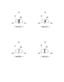
- the shapes of the individual joints 40 and the joint holes 31 in the natural length state can be appropriately determined, such as a perfect circle, an ellipse, a triangle, a rectangle (see FIG. 13), and a rhombus (see FIG. 14 (b)). It can be any shape such as a polygonal shape, a convex lens shape (see FIG. 14 (a)), a concave lens shape (see FIG. 14 (c)), a star shape, and a cloud shape.
- the dimensions of the individual joints are not particularly limited, but the maximum length 40y (approximately equal to the dimension 31y in the orthogonal direction of the joint hole 31) is 0.5 to 3.0 mm, particularly 0.7 to 1.1 mm.
- the maximum width of 40x is preferably 0.1 to 3.0 mm, and particularly preferably 0.1 to 1.1 mm in the case of a shape long in the direction XD orthogonal to the expansion / contraction direction.
- Reference numeral 40e indicates the center distance of the joint portion 40 in the orthogonal direction XD
- reference numeral 40f indicates the center distance of the joint portion 40 in the expansion / contraction direction ED.
- reference numeral 31x indicates the dimension of the expansion / contraction direction ED of the joint hole
- reference numeral 31e indicates the center distance of the orthogonal direction XD of the joint hole
- reference numeral 31f indicates the center distance of the expansion / contraction direction ED of the joint hole 31. ..
- the arrangement pattern of the joint portion 40 of the expansion / contraction region 80 is not particularly limited, and any pattern (see, for example, Patent Documents 1 to 8) can be adopted, and in particular, the example shown in FIG. 13 and the example shown in FIG. As described above, it is preferable that the non-joint zone in which the portions having no joint portion are continuous exists in an oblique lattice pattern.
- Non-stretchable area As shown in FIG. 2, of the region of the exterior body 20 having the elastic sheet elastic structure 20X, a part or all of the portion overlapping the absorber 13 (preferably including almost the entire inner / outer fixed region 10B) is desired.
- a non-stretchable region 70 can be provided at the site of.
- the non-stretchable region 70 When the non-stretchable region 70 is provided in the portion overlapping the absorber 13, its arrangement can be appropriately determined.
- the non-stretchable region 70 may be provided from the region overlapping the absorber 13 to the region not overlapping the absorber 13 located in the width direction WD or the front-rear direction LD.
- the non-stretchable region 70 means that the maximum stretch in the stretch direction is 120% or less.
- the maximum elongation of the non-stretchable region 70 is preferably 110% or less, and more preferably 100%.
- the shape of the individual joints 40 in the non-stretchable region 70 is not particularly limited, and can be appropriately selected from the same shapes as those described in the section of the stretchable region 80.
- the area ratio of the joint portion 40 and the area of each joint portion 40 in the non-stretchable region can be appropriately determined, but in the normal case, the area of each joint portion 40 is small and the joint portion is within the following range. It is preferable that the non-stretchable region 70 does not become hard due to the low area ratio of 40.
- Area of joint 40 0.10 to 0.75 mm 2 (particularly 0.10 to 0.35 mm 2 )
- Area ratio of joint 40 4 to 13% (especially 5 to 10%)
- the non-stretchable region 70 can be formed by densely arranging the joints 40 so that the first sheet layer 20A and the second sheet layer 20B do not shrink due to the contraction force of the elastic sheet 30 to form folds. ..
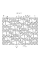
- Specific examples of the method for forming the non-stretchable region 70 include those described in Patent Document 3. 16 and 17 show an example of the non-stretchable region 70 described in Patent Document 3.
- the joint holes 31 are arranged in a staggered pattern in a dense arrangement to some extent, and the elastic sheet 30 is continuous with the expansion / contraction direction ED, but due to the presence of the joint holes 31, the joint holes 31 are linearly arranged along the expansion / contraction direction ED. It does not have a continuous part.
- the ventilation holes 33 (gap) are opened with a size that is almost the same in both the natural length state and the unfolded state.
- the joining means of the first sheet layer 20A and the second sheet layer 20B at the joining portion 40 is not particularly limited.
- the first sheet layer 20A and the second sheet layer 20B at the joining portion 40 may be joined by a hot melt adhesive or by joining means such as heat sealing or ultrasonic sealing.
- the form in which the joining portion 40 is formed by material welding is the first sheet layer in the joining portion 40.
- a first welded form in which the first sheet layer 20A and the second sheet layer 20B are joined only by a molten solidified product 20m of at least one of 20A and the second sheet layer 20B see FIG. 18A.
- a second welded form in which the first sheet layer 20A and the second sheet layer 20B are joined only by the molten solidified product 30 m of all or most or part of the elastic sheet 30 at the joint portion 40 see FIG. 18B.
- any of the third welded forms in which both of these are combined see FIG. 18C), but the second and third welded forms are preferable.
- the first sheet layer 20A due to the melted solidified 20 m of a part of the first sheet layer 20A and the second sheet layer 20B and the melted solidified product 30 m of all or most of the elastic sheet 30 at the joint portion 40. And the second sheet layer 20B are joined.
- the molten solidified product 30 m of the elastic sheet 30 can be seen between the molten solidified products 20 m of the fibers of the first sheet layer 20A or the second sheet layer 20B.
- the molten solidified product of the elastic sheet 30 is not seen between the molten solidified products 20 m of the fibers of the first sheet layer 20A or the second sheet layer 20B.
- the core (composite) of all the fibers of the joint portion 40 is such that a part of the first sheet layer 20A and the second sheet layer 20B does not melt. Not only the core of the fiber but also the central part of the single component fiber remains), but the peripheral part (including not only the sheath of the composite fiber but also the surface layer side part of the single component fiber) remains in a melted form or some fibers. Contains a form in which all the remaining fibers are melted or the core remains but the surrounding part is melted, although it does not melt at all.
- the molten solidified product 30 m of the elastic sheet 30 is the joint portion 40 as shown in FIG. 19 (c).
- the first sheet layer 20A and the second sheet layer 20B may permeate between the fibers over the entire thickness direction, but as shown in FIG. 19A, the form permeates between the fibers to the middle in the thickness direction, or the figure.
- the flexibility of the joint portion 40 is higher in the form in which the fibers of the first sheet layer 20A and the second sheet layer 20B hardly permeate.
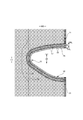
- convex regions 55 and concave regions 57 are alternately and repeatedly provided in the leg tube portion 50 while being adjacent to each other in the leg length direction orthogonal to the circumferential direction.
- the circumferential direction of the leg tube portion 50 is a direction parallel to the edge 29 of the leg opening.
- the leg length direction is the front-rear direction LD at the end portion on the side seal portion 21 side, and the width direction WD at the narrowest portion of the exterior body 20.
- the convex region 55 and the concave region 57 are elastic regions 80 having an elastic sheet elastic structure 20X.
- the first sheet layer 20A and the second sheet layer 20B in each region have folds 25 formed by swelling in opposite directions while contracting in the expansion / contraction direction together with the elastic sheet 30.
- it has folds 25 (see FIG. 13C) formed by contracting together with the elastic sheet 30 in the expansion / contraction direction (width direction WD in the example shown in FIG. 2).
- the interval 40d of the expansion / contraction direction ED of the joint portion 40 is wider than in the concave region 57
- the convex region 55 and the concave region 57 are regions in which the dimensions 55L and 57L in the leg length direction are constant, respectively.
- the dimension 55L in the leg length direction of the convex region 55 is equal to or less than the dimension 57L in the leg length direction of the concave region 57.
- a fold 25 higher and larger than the concave region 57 is formed in the convex region 55. Therefore, as shown in FIG. 10, one of the convex region 55 and the concave region 57 is relatively convex and the other is relatively concave due to the difference in thickness (difference in maximum elongation) due to the folds 25 in the contracted state. It is a thing.
- the elastic sheet expansion / contraction structure 20X can be formed by separate members in the convex region 55 and the concave region 57.
- the leg length is provided. This is preferable because the elasticity of the leg tube portion 50 is not interrupted in the longitudinal direction and the fit of the leg tube portion 50 is improved.
- the elastic sheet 30 may not be provided in the convex region 55, and the joint portion 40 may not be provided. ..
- the narrow elastic sheet 30 forming the concave region 57 is directed from one side seal portion 21 toward the center of the width direction WD along the edge 29 of the leg opening, and is in the width direction.
- a plurality of pieces may be mounted in parallel in a pattern that crosses the center of the WD toward the other leg opening LO and reaches the other side seal portion 21 along the edge 29 of the other leg opening.
- the expansion / contraction direction is the attachment direction of the elastic sheet 30, and therefore, the expansion / contraction direction is the circumferential direction of the leg tube portion 50 at the portion where the attachment direction of the elastic sheet 30 is along the edge 29 of the leg opening.
- the convex region 55 and the concave region 57 preferably form a continuous ring shape in the circumferential direction of the leg tube portion 50, but may be provided intermittently in the circumferential direction as shown in FIG.
- the convex region 55 and the concave region 57 are provided only outside the WD in the width direction from the narrowest portion of the exterior body 20 (the expansion / contraction region 80 is provided), but the illustration is limited to this. However, there may be a portion where the convex region 55 and the concave region 57 are not provided on the outer side of the width direction WD than the narrowest portion of the exterior body 20.
- the convex region 55 and the concave region 57 are alternately and repeatedly provided while being adjacent to each other in the leg length direction, and when the leg tube portion 50 is turned over and overlapped in a double manner or the like, the convex region 55 and the concave region 57 are squeezed.
- convex regions 55 and concave regions 57 can be alternately and repeatedly provided in the circumferential direction at the same position in the leg length direction (that is, the convex regions 55 and concave regions 57 have a checkered pattern). Become). In this case, the rolled-up portion of the leg tube portion 50 is difficult to move in the circumferential direction, but the tightening force in the circumferential direction changes.
- the dimension 55L in the leg length direction of the convex region 55 can be appropriately determined as long as it is equal to or less than the dimension 57L in the leg length direction of the concave region 57, but the dimension 55L in the leg length direction of the convex region 55 is the dimension 55L of the concave region 57. It is preferably smaller than the dimension 57L in the leg length direction. Further, specific dimensions can be appropriately determined. For example, in a normal case, the dimension 55L in the leg length direction of the convex region 55 can be about 5 to 10 mm, and the dimension 57L in the leg length direction of the concave region 57 can be set. It can be about 3 to 8 mm.
- the maximum elongation of the convex region 55 and the concave region 57 may be appropriately adjusted according to the degree of engagement desired for the convex region 55 and the concave region 57, but in a normal case, the maximum elongation direction of the convex region 55 is maximum. It is preferable that the elongation is 200 to 350% and the maximum elongation in the expansion / contraction direction of the concave region 57 is 0.70 to 0.95 times the maximum elongation in the expansion / contraction direction of the convex region 55.
- the presser sheet 60 is used to cover the front and rear ends of the interior body 10 mounted on the inner surface of the exterior body 20 and to prevent leakage from the front and rear edges of the interior body 10. May be provided.
- the presser sheet 60 extends over the entire width direction from the inner surface of the folded portion 20C of the inner surface of the front body F to the position where it overlaps with the front end portion of the interior body 10, and the inner surface of the rear body B.
- the folded portion 20C extends from the inner surface to a position overlapping the rear end portion of the interior body 10 over the entire width direction.
- the folded-back portion 20C can be extended to a portion overlapping the interior body 10 to form a portion equivalent to the pressing sheet 60.
- the non-woven fabric in the above description a known non-woven fabric can be appropriately used depending on the site and purpose.
- the constituent fibers of the non-woven fabric include olefin-based fibers such as polyethylene and polypropylene, polyester-based and polyamide-based synthetic fibers (including single-component fibers and composite fibers such as core sheaths), as well as recycled rayon and cupra. Fibers, natural fibers such as cotton, and the like can be selected without particular limitation, and these can be mixed and used. In order to increase the flexibility of the non-woven fabric, it is preferable that the constituent fibers are crimped fibers.
- the constituent fibers of the non-woven fabric are hydrophobic fibers or water-repellent fibers (water-repellent fibers made water-repellent by the water-repellent agent) even if they are hydrophilic fibers (including those made hydrophilic by the hydrophilic agent).
- the non-woven fabric generally has a short fiber non-woven fabric, a long fiber non-woven fabric, a spunbond non-woven fabric, a melt blown non-woven fabric, a spunlace non-woven fabric, a thermal bond (air-through) non-woven fabric, and a needle punch depending on the fiber length, the sheet forming method, the fiber bonding method, and the laminated structure.
- non-woven fabrics It is classified into non-woven fabrics, point-bonded non-woven fabrics, laminated non-woven fabrics (SMS non-woven fabrics having a melt blown layer sandwiched between spunbond layers, SMMS non-woven fabrics, etc.), and any of these non-woven fabrics can be used.
- SMS non-woven fabrics having a melt blown layer sandwiched between spunbond layers, SMMS non-woven fabrics, etc.
- the "front-back direction” means the direction indicated by the symbol LD in the figure (vertical direction), and the “width direction” means the direction indicated by the WD in the figure (horizontal direction), and the front-back direction and the width direction. Are orthogonal.
- -"MD direction” and “CD direction” mean the flow direction (MD direction) in the manufacturing equipment and the lateral direction (CD direction) orthogonal to this, and one of them is the front-back direction depending on the part of the product. And the other is in the width direction.
- the MD direction of the non-woven fabric is the direction of fiber orientation of the non-woven fabric.
- the "front surface” means the surface of the member that is closer to the wearer's skin when worn, and the “back surface” means the surface of the member that is farther from the wearer's skin when worn.
- .. -"Front body” and “rear body” mean the front and rear parts of the disposable diaper with the center in the front-rear direction as the boundary, respectively.
- “Crotch portion” means a portion that is located in the crotch of the wearer, and normally, as shown in FIG. 14, the tangent line and the front and back of the edge 29 of the leg opening in the unfolded state including the center in the front-back direction. It means a range in the front-rear direction in which the acute-angled intersection angle with the direction is 45 ° or less.
- Maximum elongation means the maximum value of elongation in the expansion / contraction direction ED (in other words, elongation in the expanded state in which the first sheet layer and the second sheet layer are expanded flat without shrinkage or slack), and is in the expanded state.
- the length is expressed as a percentage when the natural length is 100%.
- Area ratio means the ratio of the target portion to the unit area, and the target portion (for example, the joint portion 40, the opening of the joint hole 31, the ventilation hole) in the target region (for example, the stretchable region 80 and the non-stretchable region 70).
- the total area of the above is divided by the area of the target area and expressed as a percentage.
- the "area ratio" in the region having a stretchable structure means the area ratio in the expanded state. In a form in which a large number of target portions are provided at intervals, it is desirable to set the target area to a size that includes 10 or more target portions and obtain the area ratio.
- Elongation rate means the value when the natural length is 100%. For example, an elongation rate of 200% is synonymous with an elongation ratio of 2 times.
- Methodsuke is measured as follows. After pre-drying the sample or test piece, leave it in a test room or device under standard conditions (test location: temperature 23 ⁇ 1 ° C., relative humidity 50 ⁇ 2%) to bring it to a constant weight. Pre-drying refers to constant weight of a sample or test piece in an environment at a temperature of 100 ° C. It is not necessary to pre-dry the fibers having an official moisture content of 0.0%. From the test piece in a constant amount, a sample having a size of 100 mm / 100 mm is cut out using a sampling template (100 mm / 100 mm). The weight of the sample is measured and multiplied by 100 to calculate the weight per square meter, which is used as the basis weight.
- the "thickness" of the absorber is the thickness measuring instrument of Ozaki Seisakusho Co., Ltd. (peacock, dial thickness gauge large type, model JB (measurement range 0 to 35 mm) or model K-4 (measurement range 0 to 50 mm)) Measure with the sample and the thickness measuring device horizontal.
- the "thickness” other than the above is automatically measured using an automatic thickness measuring device (KES-G5 handy compression measurement program) under the conditions of a load of 0.098 N / cm 2 and a pressurized area of 2 cm 2.
- the direction of "fiber orientation of the non-woven fabric” is the direction along which the fibers of the non-woven fabric follow. It can be discriminated by a simple measuring method in which the fiber orientation direction is determined from the tensile strength ratio in the direction.
- Unfolded state means a state in which it is unfolded flat without shrinkage or slack.
- the dimensions and positional relationship of each part mean the dimensions in the unfolded state, not in the natural length state.
- test or measurement shall be performed in a test room or equipment under standard conditions (test location: temperature 23 ⁇ 1 ° C, relative humidity 50 ⁇ 2%). do.
- the present invention can be used for trunks type disposable diapers as in the above example.
- Elastic sheet elastic structure 21 ... Side seal part, 22 ... Intermediate area, 24 ... Waist elastic member, 25 ... Folds, 26 ... Elastic member around the waist, 28 ... Crotch part, 29 ... Edge of leg opening, 30 ... Elastic sheet, 40 ... Joint part, 50 ... Leg tube part, 51 ... Inner thigh contact part, 55 ... Convex area, 57 ... concave area, 60 ... presser sheet, 70 ... non-stretchable area, 80 ... stretchable area.
Abstract
[Problem] To suppress an increase in thickness when a stretchable leg tube part is rolled back. [Solution] The foregoing problem is solved by a trunks-type disposable article configured as follows. Convex regions 55 and concave regions 57 are alternately and repeatedly provided in a leg tube part 50 so as to be adjacent in the leg length direction which is orthogonal to the circumferential direction. The convex regions 55 and the concave regions 57 are regions that include a first sheet layer 20A and a second sheet layer 20B, an elastic sheet 30 provided between the first and second sheet layers, and joints of the first sheet layer 20A and the second sheet layer 20B, the joints being provided at intervals therebetween. The first sheet layer 20A and the second sheet layer 20B have folds 25 that are formed through contraction in the extension/contraction direction together with the elastic sheet 30. In the convex regions 55, an interval 40d of joints 40 in the extension/contraction direction ED is greater than that in the concave regions 57. The convex regions 55 and the concave regions 57 each have a dimension that is constant in the leg length direction. The dimension of the convex regions 55 in the leg length direction is no greater than the dimension of the concave regions 57 in the leg length direction.
Description
本発明は、脚筒部のフィット性を変更可能なトランクスタイプ使い捨て着用物品に関する。
The present invention relates to a trunks type disposable wear article in which the fit of the leg tube portion can be changed.
パンツタイプ使い捨ておむつは、ウエスト開口及び一対の脚開口を有し、前側のウエスト開口の縁から後側のウエスト開口の縁にわたる外装体と、この外装体における少なくとも股間部に設けられた、吸収体を含む内装体と、外装体における前側の両側部及び後側の両側部を接合するサイドシール部とを有する構造が一般的となっている。
Pants-type disposable diapers have a waist opening and a pair of leg openings, an exterior that extends from the edge of the front waist opening to the edge of the rear waist opening, and an absorber provided at least in the crotch area of this exterior. A structure having an interior body including the above and side seal portions for joining both front side portions and rear side side portions of the exterior body is common.
また、パンツタイプ使い捨ておむつの一形態として、腿の付根側を取り囲む一対の脚筒部を有するトランクスタイプ(一分丈形状又はボクサータイプとも呼ばれる)使い捨ておむつも知られている(例えば特許文献1、2参照)。
In addition, as one form of pants-type disposable diapers, trunks-type (also called one-quarter length or boxer-type) disposable diapers having a pair of leg cylinders surrounding the base side of the thigh are also known (for example, Patent Document 1, Patent Document 1, 2).
トランクスタイプ使い捨ておむつにおいては、脚筒部に弾性部材を取り付けることにより、脚筒部に周方向に弾性伸縮する伸縮領域が設けられる。脚筒部に取り付けられる弾性部材としては、糸ゴム等の細長状の弾性部材が一般的である。
In trunks type disposable diapers, by attaching an elastic member to the leg tube, an elastic region that elastically expands and contracts in the circumferential direction is provided in the leg tube. As the elastic member attached to the leg tube portion, an elongated elastic member such as rubber thread is generally used.
また、トランクスタイプ使い捨ておむつにおいては、装着者により異なる脚周り寸法等に応じて、脚筒部の締め付け圧力を調節可能とする要望がある(例えば特許文献1、2参照)。
Further, in trunks type disposable diapers, there is a demand that the tightening pressure of the leg tube can be adjusted according to the leg circumference and the like which differ depending on the wearer (see, for example, Patent Documents 1 and 2).
このような要望に対して、本発明者は、着用者が必要に応じて脚筒部を捲り返して二重等に重ねることにより、脚筒部の単位接触面積あたりの弾性部材の数が増加するため、締め付け圧力を強くできるとの知見を得た。
In response to such a request, the present inventor increases the number of elastic members per unit contact area of the leg tube portion by turning over the leg tube portion as necessary and stacking the leg tube portions in a double layer or the like. Therefore, it was found that the tightening pressure can be increased.
しかしながら、弾性部材により構成される伸縮領域は、一重であってもある程度収縮した装着状態では襞が(皺含む。以下同じ。)形成され、厚みが増加するものであるため、これを二重等にした場合、さらに厚みが増加し、外観や装着感が悪化するおそれがあった。
However, in the elastic region composed of the elastic member, folds (including wrinkles; the same applies hereinafter) are formed and the thickness increases in the wearing state where the elastic member is contracted to some extent even if it is single. If it is set to, the thickness may be further increased, and the appearance and wearing feeling may be deteriorated. Twice
そこで本発明の主たる課題は、伸縮性を有する脚筒部を捲り返したときの厚みの増加を抑制すること等にある。
Therefore, the main object of the present invention is to suppress an increase in thickness when the elastic leg tube portion is turned over.
上記課題を解決したトランクスタイプ使い捨て着用物品は以下のとおりである。
<第1の態様>
腿の付根側を取り囲む一対の脚筒部を備え、
前記脚筒部には、凸領域と凹領域とが、周方向と直交する脚長さ方向に隣接しつつ交互に繰り返し設けられており、
前記凸領域及び前記凹領域は、第1シート層及び第2シート層が重ねられた領域であり、
前記凸領域は、前記第1シート層及び前記第2シート層が接合されていないか、又は間隔を空けて設けられた前記第1シート層及び前記第2シート層の接合部を有しており、
前記凹領域は、間隔を空けて設けられた前記第1シート層及び前記第2シート層の接合部を有しており、
少なくとも前記凹領域における前記第1シート層及び前記第2シート層の間には弾性シートが設けられており、
前記凸領域及び前記凹領域における前記第1シート層及び第2シート層は、前記弾性シートとともに伸縮方向に収縮しつつ互いに反対向きに膨らんで形成された襞を有しており、
前記凹領域よりも前記凸領域の方が、前記接合部の前記伸縮方向の間隔が広く、
前記凸領域及び凹領域は、前記脚長さ方向の寸法がそれぞれ一定であり、
前記凸領域の前記脚長さ方向の寸法が、前記凹領域の前記脚長さ方向の寸法以下である、
ことを特徴とするトランクスタイプ使い捨て着用物品。 The trunks type disposable wear items that have solved the above problems are as follows.
<First aspect>
It has a pair of leg tubes that surround the base of the thigh.
Convex regions and concave regions are alternately and repeatedly provided in the leg tube portion while being adjacent to each other in the leg length direction orthogonal to the circumferential direction.
The convex region and the concave region are regions in which the first sheet layer and the second sheet layer are overlapped.
The convex region has a joint portion between the first sheet layer and the second sheet layer, which is not joined to the first sheet layer and the second sheet layer, or is provided at intervals. ,
The concave region has a joint portion between the first sheet layer and the second sheet layer provided at intervals.
An elastic sheet is provided between the first sheet layer and the second sheet layer at least in the concave region.
The first sheet layer and the second sheet layer in the convex region and the concave region have folds formed by expanding in opposite directions while contracting in the expansion / contraction direction together with the elastic sheet.
In the convex region, the distance between the joints in the expansion and contraction direction is wider than that in the concave region.
The convex region and the concave region have constant dimensions in the leg length direction, respectively.
The dimension of the convex region in the leg length direction is equal to or less than the dimension of the concave region in the leg length direction.
Trunks type disposable wear goods characterized by that.
(作用効果)
本トランクスタイプ使い捨ておむつの脚筒部では、凸領域及び凹領域が脚長さ方向に隣接しつつ交互に繰り返し設けられる。また、少なくとも凹領域は弾性シートを有し、凸領域及び凹領域における第1シート層及び第2シート層は、自然長及びある程度収縮した装着状態では、弾性シートとともに伸縮方向に収縮しつつ互いに反対向きに膨らんで形成された襞を有する。凸領域単独では凹領域より伸縮しない(弾性シート等の弾性部材を有しないことも含む)場合であっても、隣接する凹領域とともに収縮して襞が形成される。ここで、凹領域よりも凸領域の方が、接合部の伸縮方向の間隔が広いと、少なくとも装着状態(例えば伸縮方向に最大伸びの半分まで伸長した状態)では凸領域に凹領域よりも高く大きな襞が形成されることとなる。したがって、凸領域及び凹領域は、収縮状態での襞による厚みの差(最大伸びの差)により一方が相対的に凸、他方が相対的に凹となるものである。そして、このような凸領域及び凹領域を有すると、着用者が必要に応じて脚筒部を捲り返して二重等に重ねる際、凸領域と凹領域とを?み合わせることができる。よって、厚みの増加を抑制しつつ締め付け圧力を強くすることができる。また、これは当初予想しなかったことであるが、凸領域及び凹領域の噛み合わせにより、捲り返した部分がズレ難くなるという利点ももたらされる。 (Action effect)
In the leg tube portion of this trunks type disposable diaper, convex regions and concave regions are alternately and repeatedly provided adjacent to each other in the leg length direction. Further, at least the concave region has an elastic sheet, and the first sheet layer and the second sheet layer in the convex region and the concave region are opposite to each other while contracting in the expansion / contraction direction together with the elastic sheet in the natural length and the state of being contracted to some extent. It has folds that bulge in the direction. Even if the convex region alone does not expand or contract from the concave region (including the case where it does not have an elastic member such as an elastic sheet), it contracts together with the adjacent concave region to form folds. Here, if the convex region has a wider distance in the expansion / contraction direction of the joint than the concave region, the convex region is higher than the concave region at least in the mounted state (for example, in the state of extending to half of the maximum elongation in the expansion / contraction direction). Large folds will be formed. Therefore, one of the convex region and the concave region is relatively convex and the other is relatively concave due to the difference in thickness (difference in maximum elongation) due to the folds in the contracted state. Then, when the wearer has such a convex region and a concave region, the convex region and the concave region can be engaged with each other when the wearer turns the leg tube portion and overlaps the leg cylinder portion in a double manner or the like. Therefore, the tightening pressure can be increased while suppressing the increase in thickness. In addition, although this was not initially expected, the meshing of the convex region and the concave region also brings an advantage that the rolled-up portion is less likely to shift.
<第2の態様>
前記弾性シートは、前記凸領域及び前記凹領域に設けられており、
前記凸領域における前記接合部の配置パターンと、前記凹領域における前記接合部の配置パターンとが異なる、
第1の態様のトランクスタイプ使い捨て着用物品。 <Second aspect>
The elastic sheet is provided in the convex region and the concave region, and is provided in the convex region and the concave region.
The arrangement pattern of the joint portion in the convex region and the arrangement pattern of the joint portion in the concave region are different.
The trunks type disposable wear article of the first aspect.
(作用効果)
凸領域及び凹領域に弾性シートを設けると、脚長さ方向において伸縮性が途切れることなく、脚筒部のフィット性が良好となるため好ましい。 (Action effect)
It is preferable to provide the elastic sheet in the convex region and the concave region because the elasticity is not interrupted in the leg length direction and the fit of the leg tube portion is improved.
凸領域及び凹領域に弾性シートを設けると、脚長さ方向において伸縮性が途切れることなく、脚筒部のフィット性が良好となるため好ましい。 (Action effect)
It is preferable to provide the elastic sheet in the convex region and the concave region because the elasticity is not interrupted in the leg length direction and the fit of the leg tube portion is improved.
<第3の態様>
前記脚長さ方向の同一位置には前記凸領域及び前記凹領域のいずれか一方しか設けられておらず、
前記脚筒部の脚開口側の端部には前記凸領域が設けられている、
第2の態様のトランクスタイプ使い捨て着用物品。 <Third aspect>
Only one of the convex region and the concave region is provided at the same position in the leg length direction.
The convex region is provided at the end of the leg tube portion on the leg opening side.
The trunks type disposable wear article of the second aspect.
(作用効果)
本態様の場合、脚開口側の端部までしっかりと締め付けることができるとともに、凸領域及び凹領域を?合わせるために必要となる、最小の捲り返し長さがより短くて済み、締め付け力の調節範囲がより広くなる。 (Action effect)
In the case of this embodiment, it is possible to firmly tighten to the end on the leg opening side, and the minimum turning length required for aligning the convex region and the concave region is shorter, and the tightening force can be adjusted. The range becomes wider.
<第4の態様>
前記凸領域の前記伸縮方向の最大伸びが200~350%であり、かつ前記凹領域の前記伸縮方向の最大伸びが前記凸領域の前記伸縮方向の最大伸びの0.70~0.95倍である、
第2又は3の態様のトランクスタイプ使い捨て着用物品。 <Fourth aspect>
The maximum elongation of the convex region in the expansion and contraction direction is 200 to 350%, and the maximum elongation of the concave region in the expansion and contraction direction is 0.70 to 0.95 times the maximum elongation of the convex region in the expansion and contraction direction. be,
Trunks type disposable wear article of the second or third aspect.
(作用効果)
凸領域及び凹領域が弾性シートを有する場合、最大伸びの差により一方が凸、他方が凹となるものである。したがって、凸領域及び凹領域に望まれる噛み合わせの程度に応じて、凸領域及び凹領域の最大伸びは適宜調節すればよいが、通常の場合、本態様の範囲内であることが好ましい。 (Action effect)
When the convex region and the concave region have an elastic sheet, one is convex and the other is concave due to the difference in maximum elongation. Therefore, the maximum elongation of the convex region and the concave region may be appropriately adjusted according to the degree of engagement desired in the convex region and the concave region, but it is usually preferable to be within the range of this embodiment.
<第5の態様>
ウエスト開口及び一対の脚開口を有し、前側のウエスト開口の縁から後側のウエスト開口の縁にわたる外装体と、この外装体における少なくとも股間部に設けられた、吸収体を含む内装体と、外装体における前側の両側部及び後側の両側部を接合するサイドシール部とを有し、
前記外装体における幅方向の一方のサイドシール部と他方のサイドシール部との間が、環状の胴周り部を形成しており、
前記外装体の股間部は、前記吸収体の両側縁よりも幅方向外側にそれぞれ延び出た一対の内腿接触部分を有し、これら内腿接触部分を含む、前記脚開口の縁に沿う部分が、前記脚筒部となっており、
前記外装体は、前記脚筒部から前後少なくとも一方の胴周り部に至る領域が、前記第1シート層、第2シート層及び前記弾性シートを有する領域となっている、
第1~4のいずれか1つの態様のトランクスタイプ使い捨て着用物品。 <Fifth aspect>
An exterior body having a waist opening and a pair of leg openings extending from the edge of the front waist opening to the edge of the rear waist opening, and an interior body including an absorber provided at least in the crotch portion of the exterior body. It has a side seal portion that joins both front side portions and rear side side portions of the exterior body.
An annular waist circumference is formed between one side seal portion in the width direction and the other side seal portion in the exterior body.
The crotch portion of the exterior body has a pair of inner thigh contact portions extending outward in the width direction from both side edges of the absorber, and a portion along the edge of the leg opening including these inner thigh contact portions. However, it is the leg tube part.
In the exterior body, a region extending from the leg tube portion to at least one of the front and rear waist circumference portions is a region having the first sheet layer, the second sheet layer, and the elastic sheet.
A trunks type disposable wear article according to any one of the first to fourth aspects.
(作用効果)
本態様のように、脚筒部のないパンツタイプ使い捨て着用物品と同様の基本構造を有するトランクスタイプ使い捨て着用物品とすることにより、胴周り部から脚筒部まで共通の第1シート層、第2シート層及び弾性シートを配置して伸縮性を付加することができるため好ましい。 (Action effect)
By using the trunks type disposable wear article having the same basic structure as the pants type disposable wear article without the leg tube portion as in this embodiment, the first sheet layer and the second sheet layer common from the waist circumference to the leg tube portion. It is preferable because the sheet layer and the elastic sheet can be arranged to add elasticity.
本発明によれば、伸縮性を有する脚筒部を捲り返したときの厚みの増加を抑制できるようになる、等の利点がもたらされる。
According to the present invention, there are advantages such as being able to suppress an increase in thickness when the elastic leg tube portion is turned over.
図1~図10には、一対の脚筒部50を有するトランクスタイプ使い捨て着用物品の一例として、トランクスタイプ使い捨ておむつ(以下、単におむつともいう。)が示されている。なお、ホットメルト接着剤による接着箇所のうち説明上必要な箇所については、図中に点模様をそれぞれ付している。ホットメルト接着剤は、スロット塗布、連続線状又は点線状のビード塗布、スパイラル状、Z状等のスプレー塗布、又はパターンコート(凸版方式でのホットメルト接着剤の転写)等、公知の手法により塗布することができる。これに代えて又はこれとともに、弾性部材の固定部分では、ホットメルト接着剤を弾性部材の外周面に塗布し、弾性部材を隣接部材に固定することができる。ホットメルト接着剤としては、例えばEVA系、粘着ゴム系(エラストマー系)、オレフィン系、ポリエステル・ポリアミド系などの種類のものが存在するが、特に限定無く使用できる。各構成部材を接合する接合手段としてはヒートシールや超音波シール等の素材溶着による手段を用いることもできる。
FIGS. 1 to 10 show trunks-type disposable diapers (hereinafter, also simply referred to as diapers) as an example of trunks-type disposable wear articles having a pair of leg cylinders 50. It should be noted that, among the parts bonded by the hot melt adhesive, the parts necessary for explanation are marked with dots in the figure. The hot melt adhesive can be applied by a known method such as slot coating, continuous linear or dotted bead coating, spiral or Z-shaped spray coating, or pattern coating (transfer of hot melt adhesive by letterpress method). Can be applied. Instead of or in conjunction with this, at the fixed portion of the elastic member, a hot melt adhesive can be applied to the outer peripheral surface of the elastic member to fix the elastic member to the adjacent member. Examples of the hot melt adhesive include EVA type, adhesive rubber type (elastomer type), olefin type, polyester / polyamide type and the like, but they can be used without particular limitation. As a joining means for joining each component, a means by material welding such as a heat seal or an ultrasonic seal can also be used.
トランクスタイプ使い捨ておむつの一対の脚筒部50は、装着状態で腿を取り囲む筒状をなしている限り、特に限定されるものではなく、特許文献1、2記載の構造を採用することもできる。これに対して、図示例のトランクスタイプ使い捨ておむつは、特許文献1、2記載のものよりも簡素な構造を採用するものである。
The pair of leg tube portions 50 of the trunks type disposable diaper is not particularly limited as long as it has a tubular shape surrounding the thigh in the worn state, and the structures described in Patent Documents 1 and 2 can be adopted. On the other hand, the trunks type disposable diaper shown in the illustrated example adopts a structure simpler than that described in Patent Documents 1 and 2.
より詳細には、図示例のトランクスタイプ使い捨ておむつは、ウエスト開口WO及び一対の脚開口LOを有し、前身頃Fのウエスト開口WOの縁から後身頃Bのウエスト開口WOの縁にわたる外装体20と、この外装体20における少なくとも股間部28に設けられた、吸収体13を含む内装体10と、外装体20における前側の両側部及び後側の両側部を接合するサイドシール部21とを有するものである。また、外装体20の股間部28は、吸収体13の両側縁よりも幅方向WD一方側及び他方側にそれぞれ延び出た一対の内腿接触部分51を有し、これら内腿接触部分51を含む、脚開口の縁29に沿う部分が、腿の付根側を取り囲む一対の脚筒部50となっている。製造に際しては、外装体20に対して内装体10がホットメルト接着剤などの接合手段によって接合された後に、内装体10及び外装体20が前身頃F及び後身頃Bの境界である前後方向LD(縦方向)中央で折り畳まれ、その両側部が相互に熱溶着又はホットメルト接着剤などによって接合されてサイドシール部21が形成されることによって、ウエスト開口WO及び一対の脚開口LOが形成されたトランクスタイプ使い捨ておむつとなる。
More specifically, the trunks type disposable diaper of the illustrated example has a waist opening WO and a pair of leg openings LO, and an exterior body 20 extending from the edge of the waist opening WO of the front body F to the edge of the waist opening WO of the back body B. And an interior body 10 including an absorber 13 provided at least in the crotch portion 28 of the exterior body 20, and side seal portions 21 for joining both front side portions and rear side side portions of the exterior body 20. It is a thing. Further, the crotch portion 28 of the exterior body 20 has a pair of inner thigh contact portions 51 extending from both side edges of the absorber 13 to one side and the other side of the WD in the width direction, respectively, and these inner thigh contact portions 51 are provided. The portion along the edge 29 of the leg opening including the leg opening is a pair of leg tube portions 50 surrounding the base side of the thigh. In manufacturing, after the interior body 10 is joined to the exterior body 20 by a joining means such as a hot melt adhesive, the interior body 10 and the exterior body 20 are the boundaries between the front body F and the back body B in the front-rear direction LD. A waist opening WO and a pair of leg openings LO are formed by folding at the center (vertical direction) and joining both side portions to each other by heat welding or hot melt adhesive to form a side seal portion 21. It becomes a trunks type disposable diaper.
(内装体の構造例)
内装体10は、図3~図6に示すように、不織布などからなる液透過性のトップシート11と、ポリエチレン等からなる液不透過性シート12との間に、吸収体13を介在させた構造を有しており、トップシート11を透過した排泄液を吸収保持するものである。内装体10の平面形状は特に限定されないが、図示形態のようにほぼ長方形とすることが一般的である。 (Example of interior structure)
As shown in FIGS. 3 to 6, theinterior body 10 has an absorber 13 interposed between the liquid-permeable top sheet 11 made of a non-woven fabric or the like and the liquid-impermeable sheet 12 made of polyethylene or the like. It has a structure and absorbs and retains the excrement liquid that has passed through the top sheet 11. The planar shape of the interior body 10 is not particularly limited, but it is generally a substantially rectangular shape as shown in the illustrated form.
内装体10は、図3~図6に示すように、不織布などからなる液透過性のトップシート11と、ポリエチレン等からなる液不透過性シート12との間に、吸収体13を介在させた構造を有しており、トップシート11を透過した排泄液を吸収保持するものである。内装体10の平面形状は特に限定されないが、図示形態のようにほぼ長方形とすることが一般的である。 (Example of interior structure)
As shown in FIGS. 3 to 6, the
吸収体13の表側を覆い、肌当接面を形成するトップシート11としては、有孔又は無孔の不織布や有孔プラスチックシートなどが好適に用いられる。不織布を構成する素材繊維は、ポリエチレン又はポリプロピレン等のオレフィン系、ポリエステル系、ポリアミド系等の合成繊維の他、レーヨンやキュプラ等の再生繊維、綿等の天然繊維とすることができ、スパンレース法、スパンボンド法、サーマルボンド法、メルトブローン法、ニードルパンチ法等の適宜の加工法によって得られた不織布を用いることができる。これらの加工法の内、スパンレース法は柔軟性、ドレープ性に富む点で優れ、サーマルボンド法は嵩高でソフトである点で優れている。トップシート11に多数の透孔を形成した場合には、尿などが速やかに吸収されるようになり、ドライタッチ性に優れたものとなる。図示形態では、トップシート11は、吸収体13の側縁部を巻き込んで吸収体13の裏面側まで延在しているが、これに限定されるものではない。
As the top sheet 11 that covers the front side of the absorber 13 and forms the skin contact surface, a perforated or non-perforated non-woven fabric, a perforated plastic sheet, or the like is preferably used. The material fibers constituting the non-woven fabric can be olefin-based fibers such as polyethylene or polypropylene, synthetic fibers such as polyester-based and polyamide-based, recycled fibers such as rayon and cupra, and natural fibers such as cotton. , A non-woven fabric obtained by an appropriate processing method such as a spun bond method, a thermal bond method, a melt blown method, or a needle punch method can be used. Among these processing methods, the spunlace method is excellent in that it is rich in flexibility and drapeability, and the thermal bond method is excellent in that it is bulky and soft. When a large number of through holes are formed in the top sheet 11, urine or the like is quickly absorbed, and the dry touch property is excellent. In the illustrated embodiment, the top sheet 11 involves the side edge portion of the absorber 13 and extends to the back surface side of the absorber 13, but is not limited to this.
吸収体13の裏側を覆う液不透過性シート12は、ポリエチレン又はポリプロピレンなどの液不透過性プラスチックシートが用いられるが、近年はムレ防止の点から透湿性を有するものが好適に用いられる。この遮水・透湿性シートとしては、例えばポリエチレンやポリプロピレン等のオレフィン樹脂中に無機充填材を溶融混練してシートを形成した後、一軸又は二軸方向に延伸することにより得られる微多孔性シートを挙げることができる。
As the liquid-impermeable sheet 12 covering the back side of the absorber 13, a liquid-impermeable plastic sheet such as polyethylene or polypropylene is used, but in recent years, a liquid-impermeable sheet having moisture permeability is preferably used from the viewpoint of preventing stuffiness. The water-impervious / moisture-permeable sheet is a microporous sheet obtained by melting and kneading an inorganic filler in an olefin resin such as polyethylene or polypropylene to form a sheet, and then stretching the sheet in a uniaxial or biaxial direction. Can be mentioned.
液不透過性シート12としては、排便や尿などの褐色が出ないように不透明のものを用いるのが望ましい。不透明化としては、プラスチック中に、炭酸カルシウム、酸化チタン、酸化亜鉛、ホワイトカーボン、クレイ、タルク、硫酸バリウムなどの顔料や充填材を内添してフィルム化したものが好適に使用される。図示形態では、液不透過性シート12は、トップシート11とともに吸収体13の幅方向両側で裏側に折り返されているが、これに限定されるものではない。
As the liquid impermeable sheet 12, it is desirable to use an opaque sheet so that brown color such as defecation and urine does not appear. As the opacity, a plastic in which pigments such as calcium carbonate, titanium oxide, zinc oxide, white carbon, clay, talc, and barium sulfate and a filler are added and formed into a film is preferably used. In the illustrated form, the liquid impermeable sheet 12 is folded back on both sides in the width direction of the absorber 13 together with the top sheet 11, but the present invention is not limited to this.
吸収体13としては、公知のもの、例えばパルプ繊維の積繊体、セルロースアセテート等のフィラメントの集合体、あるいは不織布を基本とし、必要に応じて高吸収性ポリマーを混合、固着等してなるものを用いることができる。この吸収体13は、形状及びポリマー保持等のため、必要に応じてクレープ紙等の、液透過性及び液保持性を有する包装シート14によって包装することができる。
The absorber 13 is basically a known material, for example, a stack of pulp fibers, an aggregate of filaments such as cellulose acetate, or a non-woven fabric, and a highly absorbent polymer is mixed and fixed as necessary. Can be used. The absorber 13 can be packaged with a liquid-permeable and liquid-retaining packaging sheet 14 such as crepe paper, if necessary, in order to retain the shape and polymer.
吸収体13の全体形状は、股間部28を含む前後方向範囲にその前後両側よりも幅の狭い括れ部13Nを有するほぼ砂時計状に形成されているが、長方形状等、適宜の形状とすることができる。括れ部13Nの寸法は適宜定めることができるが、括れ部13Nの前後方向長さはおむつ全長の20~50%程度とすることができ、その最も狭い部分13mの幅は吸収体13の全幅13wの40~60%程度とすることができる。このような括れ部13Nを有する場合において、内装体10の平面形状がほぼ長方形とされていると、内装体10における吸収体13の括れ部13Nと対応する部分に、吸収体13を有しない余り部分が形成される。
The overall shape of the absorber 13 is formed in a substantially hourglass shape having a constricted portion 13N narrower than both front and rear sides in the front-rear direction range including the crotch portion 28, but the overall shape should be an appropriate shape such as a rectangular shape. Can be done. The dimensions of the constricted portion 13N can be appropriately determined, but the length of the constricted portion 13N in the front-rear direction can be about 20 to 50% of the total length of the diaper, and the width of the narrowest portion 13 m is the total width 13 w of the absorber 13. It can be about 40 to 60% of. In the case of having such a constricted portion 13N, if the planar shape of the interior body 10 is substantially rectangular, the portion of the interior body 10 corresponding to the constricted portion 13N of the absorber 13 does not have the absorber 13. A part is formed.
内装体10の両側部には脚周りにフィットする立体ギャザーBSが形成されている。この立体ギャザーBSは、図5及び図6に示されるように、内装体10の裏面の側部に固定された固定部と、この固定部から内装体10の側方を経て内装体10の表面の側部まで延在する本体部と、本体部の前後端部が倒伏状態で内装体10の表面の側部に固定されて形成された倒伏部分と、この倒伏部分間が非固定とされて形成された自由部分とが、折返しによって二重としたギャザーシート15により形成されている。ギャザーシート15としては撥水性とされた不織布が好適に用いられる。
Three-dimensional gather BSs that fit around the legs are formed on both sides of the interior body 10. As shown in FIGS. 5 and 6, the three-dimensional gather BS has a fixed portion fixed to the side portion of the back surface of the interior body 10, and the surface of the interior body 10 from this fixed portion via the side of the interior body 10. The main body portion extending to the side portion of the main body, the inverted portion formed by fixing the front and rear ends of the main body portion to the side portion of the surface of the interior body 10 in an inverted state, and the portion of this inverted portion are not fixed. The formed free portion is formed by a gather sheet 15 that is doubled by folding back. As the gather sheet 15, a non-woven fabric having water repellency is preferably used.
また、二重のギャザーシート15の間には、自由部分の先端部等に細長状のギャザー弾性部材16が配設されている。ギャザー弾性部材16は、製品状態において図5に二点鎖線で示すように、弾性伸縮力により自由部分を起立させて立体ギャザーBSを形成するためのものである。
Further, between the double gather sheets 15, an elongated gather elastic member 16 is arranged at the tip of a free portion or the like. The gather elastic member 16 is for forming a three-dimensional gather BS by erecting a free portion by an elastic elastic force as shown by a two-dot chain line in FIG. 5 in a product state.
ギャザー弾性部材16としては、通常使用されるスチレン系ゴム、オレフィン系ゴム、ウレタン系ゴム、エステル系ゴム、ポリウレタン、ポリエチレン、ポリスチレン、スチレンブタジエン、シリコーン、ポリエステル等の素材を用いることができる。また、外側から見え難くするため、太さは925dtex以下、伸長率は150~350%、間隔は10.0mm以下として配設するのがよい。なお、ギャザー弾性部材16としては、図示形態のような糸状の他、ある程度の幅を有するテープ状のものを用いることもできる。
As the gather elastic member 16, materials such as styrene rubber, olefin rubber, urethane rubber, ester rubber, polyurethane, polyethylene, polystyrene, styrene butadiene, silicone, and polyester, which are usually used, can be used. Further, in order to make it difficult to see from the outside, it is preferable to arrange the thickness at 925 dtex or less, the elongation rate at 150 to 350%, and the interval at 10.0 mm or less. As the gather elastic member 16, a tape-shaped member having a certain width can be used in addition to the thread-shaped member as shown in the illustrated figure.
ギャザーシート15に用いる不織布は特に限定されるものではなく、ポリエチレン又はポリプロピレン等のオレフィン系、ポリエステル系、ポリアミド系等の合成繊維の他、レーヨンやキュプラ等の再生繊維、綿等の天然繊維からなるものとすることができ、また、スパンボンド法、サーマルボンド法、メルトブローン法、ニードルパンチ法等の適宜の加工方法により製造することができる。特に、ギャザーシート15としては、尿などの透過を防止するために、シリコーン系、パラフィン金属系、アルキルクロミッククロライド系撥水剤などをコーティングした撥水処理不織布を用いるのが望ましい。
The non-woven fabric used for the gather sheet 15 is not particularly limited, and is made of olefin-based fibers such as polyethylene or polypropylene, synthetic fibers such as polyester-based and polyamide-based, recycled fibers such as rayon and cupra, and natural fibers such as cotton. It can also be produced by an appropriate processing method such as a spunbond method, a thermal bond method, a melt blown method, or a needle punch method. In particular, as the gather sheet 15, it is desirable to use a water-repellent treated non-woven fabric coated with a silicone-based, paraffin metal-based, alkylchromic chloride-based water repellent, or the like in order to prevent permeation of urine or the like.
(外装体)
図1、図2、及び図8に示すように、外装体20は、前後方向LDの中間が括れたほぼ砂時計形状となっており、この括れの両側縁がそれぞれ脚開口の縁29となっている。そして、前述のとおり、外装体20の股間部28には、吸収体13の両側縁よりも幅方向WDの一方側及び他方側にそれぞれ延び出た一対の内腿接触部分51を有し、これら内腿接触部分51を含む、脚開口の縁29に沿う部分が、腿の付根側を取り囲む一対の脚筒部50となっている。内腿接触部分51の寸法は脚筒部50の長さに応じて適宜定めれば良いが、通常の場合、外装体20の最も幅の狭い部分における内腿接触部分51の幅51xは、おむつ全長のYの1~5%程度とすることが好ましい。また、図9に示すように、前身頃Fにおいては、脚開口の縁29上の最も幅方向中央側に位置する仮想点P1から、幅方向に対して20度の角度θ1で、幅方向外側かつウエスト側に向かう仮想直線L1を引いたとき、この仮想直線L1と、サイドシール部21を有する前後方向範囲における外装体20の側縁との交点P2を有するのが好ましく、この交点P2から脚開口の縁29までの前後方向間隔50fは、外装体20の最も幅の狭い部分における外装体20の側縁と内装体10の側縁との間隔51d以上であることが好ましく、ほぼ同じであることが好ましい。一方、後身頃Bにおいては、脚開口の縁29上の最も幅方向中央側に位置する仮想点P1から、幅方向に対して30度の角度θ2で、幅方向外側かつウエスト側に向かう仮想直線L2を引いたとき、この仮想直線L2と、サイドシール部21を有する前後方向範囲における外装体20の側縁との交点P3を有するのが好ましく、この交点P3から脚開口の縁29までの前後方向間隔50bは、外装体20の最も幅の狭い部分における外装体20の側縁と内装体10の側縁との間隔51d以下であっても、以上であってもよい。 (Exterior body)
As shown in FIGS. 1, 2, and 8, theexterior body 20 has a substantially hourglass shape in which the middle of the LD in the front-rear direction is constricted, and both side edges of the constriction are edges 29 of the leg openings, respectively. There is. As described above, the crotch portion 28 of the exterior body 20 has a pair of inner thigh contact portions 51 extending from both side edges of the absorber 13 to one side and the other side of the WD in the width direction, respectively. A portion along the edge 29 of the leg opening, including the inner thigh contact portion 51, is a pair of leg tube portions 50 surrounding the base side of the thigh. The dimensions of the inner thigh contact portion 51 may be appropriately determined according to the length of the leg tube portion 50, but usually, the width 51x of the inner thigh contact portion 51 in the narrowest portion of the exterior body 20 is a diaper. It is preferably about 1 to 5% of the total length Y. Further, as shown in FIG. 9, in the front body F, the width direction is at an angle θ 1 of 20 degrees with respect to the width direction from the virtual point P1 located on the edge 29 of the leg opening on the most width direction center side. When the virtual straight line L1 toward the outside and the waist side is drawn, it is preferable to have an intersection P2 between this virtual straight line L1 and the side edge of the exterior body 20 in the front-rear direction range having the side seal portion 21, and from this intersection P2. The distance between the front and rear directions 50f to the edge 29 of the leg opening is preferably 51d or more between the side edge of the exterior body 20 and the side edge of the interior body 10 in the narrowest portion of the exterior body 20, and is substantially the same. It is preferable to have. On the other hand, in the back body B, the virtual point P1 located on the edge 29 of the leg opening on the most central side in the width direction is virtual toward the outside and the waist side in the width direction at an angle θ 2 of 30 degrees with respect to the width direction. When the straight line L2 is drawn, it is preferable to have an intersection P3 between this virtual straight line L2 and the side edge of the exterior body 20 in the front-rear direction range having the side seal portion 21, and from this intersection P3 to the edge 29 of the leg opening. The distance between the front and rear directions 50b may be 51d or less or more than the distance between the side edge of the exterior body 20 and the side edge of the interior body 10 in the narrowest portion of the exterior body 20.
図1、図2、及び図8に示すように、外装体20は、前後方向LDの中間が括れたほぼ砂時計形状となっており、この括れの両側縁がそれぞれ脚開口の縁29となっている。そして、前述のとおり、外装体20の股間部28には、吸収体13の両側縁よりも幅方向WDの一方側及び他方側にそれぞれ延び出た一対の内腿接触部分51を有し、これら内腿接触部分51を含む、脚開口の縁29に沿う部分が、腿の付根側を取り囲む一対の脚筒部50となっている。内腿接触部分51の寸法は脚筒部50の長さに応じて適宜定めれば良いが、通常の場合、外装体20の最も幅の狭い部分における内腿接触部分51の幅51xは、おむつ全長のYの1~5%程度とすることが好ましい。また、図9に示すように、前身頃Fにおいては、脚開口の縁29上の最も幅方向中央側に位置する仮想点P1から、幅方向に対して20度の角度θ1で、幅方向外側かつウエスト側に向かう仮想直線L1を引いたとき、この仮想直線L1と、サイドシール部21を有する前後方向範囲における外装体20の側縁との交点P2を有するのが好ましく、この交点P2から脚開口の縁29までの前後方向間隔50fは、外装体20の最も幅の狭い部分における外装体20の側縁と内装体10の側縁との間隔51d以上であることが好ましく、ほぼ同じであることが好ましい。一方、後身頃Bにおいては、脚開口の縁29上の最も幅方向中央側に位置する仮想点P1から、幅方向に対して30度の角度θ2で、幅方向外側かつウエスト側に向かう仮想直線L2を引いたとき、この仮想直線L2と、サイドシール部21を有する前後方向範囲における外装体20の側縁との交点P3を有するのが好ましく、この交点P3から脚開口の縁29までの前後方向間隔50bは、外装体20の最も幅の狭い部分における外装体20の側縁と内装体10の側縁との間隔51d以下であっても、以上であってもよい。 (Exterior body)
As shown in FIGS. 1, 2, and 8, the
そして、図示例の外装体20では、図2及び図4~図6、及び図8に示されるように、第1シート層20A及び第2シート層20Bの間に、弾性シート30が介在されるとともに、図13に示されるように、第1シート層20A及び第2シート層20Bが、間隔を空けて配列された多数の接合部40で弾性シート30を貫通する接合孔31を通じて接合された弾性シート伸縮構造20Xを有している。つまり、接合部40の外周縁は接合孔31の内周縁により囲まれており、両者は接合されておらず、離間可能である。図示しないが、第1シート層20A及び第2シート層20Bは、間隔を空けて配列された多数の接合部40で弾性シート30を介して接合されていてもよい。そして、この弾性シート伸縮構造20Xを有する領域は、弾性シート30の収縮により幅方向に収縮しているとともに幅方向WDに伸長可能である(つまり伸縮方向EDがおむつの幅方向WDとなる)伸縮領域を有している。
Then, in the exterior body 20 of the illustrated example, as shown in FIGS. 2 and 4 to 6 and 8, the elastic sheet 30 is interposed between the first sheet layer 20A and the second sheet layer 20B. At the same time, as shown in FIG. 13, the elasticity of the first sheet layer 20A and the second sheet layer 20B being joined through a joint hole 31 penetrating the elastic sheet 30 at a large number of joints 40 arranged at intervals. It has a sheet elastic structure 20X. That is, the outer peripheral edge of the joint portion 40 is surrounded by the inner peripheral edge of the joint hole 31, and the two are not joined and can be separated from each other. Although not shown, the first sheet layer 20A and the second sheet layer 20B may be joined via the elastic sheet 30 by a large number of joints 40 arranged at intervals. The region having the elastic sheet expansion / contraction structure 20X is contracted in the width direction due to the contraction of the elastic sheet 30 and can be expanded in the width direction WD (that is, the expansion / contraction direction ED becomes the width direction WD of the diaper). Has an area.
図示しないが、弾性シート伸縮構造で外装体20のウエスト端部23までを含む領域の伸縮性を構成することは可能である。しかし、より好適なフィット性を実現するためには困難な場合が多いため、図示例のように、ウエスト端部23には弾性シート伸縮構造20Xを設けずに、従来の細長状のウエスト弾性部材24による伸縮構造を設けるのも好ましい。ウエスト弾性部材24は、前後方向LDに間隔をおいて配置された複数の糸ゴム等の細長状弾性部材であり、身体の胴周りを締め付けるように伸縮力を与えるものである。ウエスト弾性部材24は、間隔を密にして実質的に一束として配置されるのではなく、所定の伸縮ゾーンを形成するように前後方向に3~8mm程度の間隔を空けて、3本以上、好ましくは5本以上配置される。ウエスト弾性部材24の固定時の伸長率は適宜定めることができるが、通常の成人用の場合230~320%程度とすることができる。ウエスト弾性部材24は、図示例では糸ゴムを用いたが、例えば平ゴム等、他の細長状の伸縮部材を用いても良い。図示しないが、ウエスト端部23に弾性シート30を設けるとともに、弾性シート30と重なる位置に細長状のウエスト弾性部材24を設け、両方の弾性部材による伸縮構造とすることもできる。
Although not shown, it is possible to configure the elasticity of the region including the waist end 23 of the exterior body 20 with the elastic sheet elastic structure. However, since it is often difficult to achieve a more suitable fit, as shown in the illustrated example, the waist end portion 23 is not provided with the elastic sheet elastic structure 20X, and the conventional elongated waist elastic member is not provided. It is also preferable to provide an elastic structure according to 24. The waist elastic member 24 is an elongated elastic member such as a plurality of elastic threads arranged at intervals in the front-rear direction LD, and gives an elastic force so as to tighten around the waist of the body. The waist elastic members 24 are not arranged as a bundle with close intervals, but are arranged at intervals of about 3 to 8 mm in the front-rear direction so as to form a predetermined expansion / contraction zone. Preferably, 5 or more are arranged. The elongation rate at the time of fixing the waist elastic member 24 can be appropriately determined, but in the case of a normal adult, it can be about 230 to 320%. As the waist elastic member 24, thread rubber is used in the illustrated example, but other elongated elastic members such as flat rubber may be used. Although not shown, an elastic sheet 30 may be provided at the waist end 23, and an elongated waist elastic member 24 may be provided at a position overlapping the elastic sheet 30 to form an elastic structure composed of both elastic members.
後述するように、脚筒部50は弾性シート伸縮構造20Xを有する。この場合、脚筒部50とそれ以外の部位において、別々の部材により弾性シート伸縮構造20Xを構成することもできるが、製造容易性等の観点から、図示例のように、外装体20は、脚筒部50から前後少なくとも一方の胴周り部に至る領域が、単一の弾性シート伸縮構造20Xを有する領域となっていると好ましい。また、脚筒部50には後述する凸領域55及び凹領域57の形成のため、脚開口LOに沿って延びる細長状弾性部材等、弾性シート30以外の弾性部材は設けられていない。
As will be described later, the leg tube portion 50 has an elastic sheet telescopic structure 20X. In this case, the elastic sheet telescopic structure 20X can be formed by separate members in the leg tube portion 50 and other parts, but from the viewpoint of ease of manufacture and the like, the exterior body 20 is as shown in the illustrated example. It is preferable that the region from the leg tube portion 50 to at least one of the front and rear waist circumference portions is a region having a single elastic sheet telescopic structure 20X. Further, the leg tube portion 50 is not provided with an elastic member other than the elastic sheet 30 such as an elongated elastic member extending along the leg opening LO because of the formation of the convex region 55 and the concave region 57, which will be described later.
図12に示すように、胴周り部におけるウエスト端部23以外の部分には弾性シート伸縮構造20Xを設けずに、糸ゴム等の、従来の細長状のウエスト弾性部材26による伸縮構造を設けることもできる。
As shown in FIG. 12, the elastic sheet expansion / contraction structure 20X is not provided in the portion other than the waist end portion 23 in the waist circumference portion, but the expansion / contraction structure by the conventional elongated waist elastic member 26 such as thread rubber is provided. You can also.
(伸縮領域)
外装体20における弾性シート伸縮構造20Xを有する領域は、幅方向WDに伸縮可能な伸縮領域80を有している。伸縮領域80では、弾性シート30の収縮力により幅方向WDに収縮しているとともに、幅方向WDに伸長可能となっている。より具体的には、弾性シート30を幅方向WDに伸長した状態で、幅方向WD及びこれと直交する前後方向LD(伸縮方向と直交する方向LD)にそれぞれ間隔を空けて、弾性シート30の接合孔31を介して第1シート層20A及び第2シート層20Bを接合し、多数の接合部40を形成することにより、弾性シート伸縮構造20Xを形成するとともに、伸縮領域80では弾性シート30が幅方向WDに途切れずに残り、かつこの弾性シート30の収縮力により第1シート層20A及び第2シート層20Bが収縮して収縮襞25が形成されるように接合部40を配置することによって、このような伸縮性を付与することができる。 (Expandable area)
The region of theexterior body 20 having the elastic sheet elastic structure 20X has an elastic region 80 that can be expanded and contracted in the width direction WD. In the expansion / contraction region 80, the elastic sheet 30 contracts in the width direction WD due to the contraction force of the elastic sheet 30, and can expand in the width direction WD. More specifically, in a state where the elastic sheet 30 is extended in the width direction WD, the elastic sheet 30 is separated from each other in the width direction WD and the front-rear direction LD (direction LD orthogonal to the expansion / contraction direction) orthogonal to the width direction WD. The elastic sheet elastic structure 20X is formed by joining the first sheet layer 20A and the second sheet layer 20B through the joint hole 31 to form a large number of joint portions 40, and the elastic sheet 30 is formed in the elastic region 80. By arranging the joint 40 so that the first sheet layer 20A and the second sheet layer 20B are contracted by the contraction force of the elastic sheet 30 to form the contraction folds 25 while remaining uninterrupted in the width direction WD. , Such elasticity can be imparted.
外装体20における弾性シート伸縮構造20Xを有する領域は、幅方向WDに伸縮可能な伸縮領域80を有している。伸縮領域80では、弾性シート30の収縮力により幅方向WDに収縮しているとともに、幅方向WDに伸長可能となっている。より具体的には、弾性シート30を幅方向WDに伸長した状態で、幅方向WD及びこれと直交する前後方向LD(伸縮方向と直交する方向LD)にそれぞれ間隔を空けて、弾性シート30の接合孔31を介して第1シート層20A及び第2シート層20Bを接合し、多数の接合部40を形成することにより、弾性シート伸縮構造20Xを形成するとともに、伸縮領域80では弾性シート30が幅方向WDに途切れずに残り、かつこの弾性シート30の収縮力により第1シート層20A及び第2シート層20Bが収縮して収縮襞25が形成されるように接合部40を配置することによって、このような伸縮性を付与することができる。 (Expandable area)
The region of the
伸縮領域80では、図13に示す例のように弾性シート30が幅方向WDに沿って直線的に連続する部分32を有していても、図11に示す例及び図15に示す例のように有していなくてもよい。
In the expansion / contraction region 80, even if the elastic sheet 30 has a portion 32 linearly continuous along the width direction WD as in the example shown in FIG. 13, the example shown in FIG. 11 and the example shown in FIG. You do not have to have it.
伸縮領域80は、自然長状態では、図13(c)(d)に示すように、接合部40間の第1シート層20A及び第2シート層20Bが互いに反対向きに(離間するように)膨らんで、前後方向LDに延びる収縮襞25が形成され、幅方向WDにある程度伸長した装着状態でも、収縮襞25は伸ばされるものの、残るようになっている。また、図示例のように、第1シート層20A及び第2シート層20Bは、少なくとも接合部40における第1シート層20A及び第2シート層20B間以外では弾性シート30と接合されていないと、装着状態を想定した図13(c)、及び、第1シート層20A及び第2シート層20Bの展開状態を想定した図13(a)からも分かるように、これらの状態では、弾性シート30における接合孔31の縁が、接合部40の外周縁から伸縮方向に離れて通気孔33(隙間)が開口し、弾性シート30の素材が無孔のフィルムやシートであっても、この通気孔33により通気性が付加される。特に、弾性シート30が幅方向WDに沿って直線的に連続する部分32を有している場合には、自然長状態では、弾性シート30のさらなる収縮により接合孔31がすぼまり、接合孔31と接合部40との間に隙間がほとんど形成されない形態となり、弾性シート30が幅方向WDに沿って直線的に連続する部分を有していない場合には通気孔33が残る。
In the stretchable region 80, in the natural length state, as shown in FIGS. 13 (c) and 13 (d), the first sheet layer 20A and the second sheet layer 20B between the joints 40 are opposite to each other (so that they are separated from each other). The contraction folds 25 that swell and extend in the anteroposterior direction LD are formed, and even in the wearing state that extends to some extent in the width direction WD, the contraction folds 25 are extended but remain. Further, as shown in the illustrated example, the first sheet layer 20A and the second sheet layer 20B are not joined to the elastic sheet 30 except between the first sheet layer 20A and the second sheet layer 20B at least in the joint portion 40. As can be seen from FIG. 13 (c) assuming a mounted state and FIG. 13 (a) assuming a deployed state of the first sheet layer 20A and the second sheet layer 20B, in these states, the elastic sheet 30 Even if the edge of the joint hole 31 is separated from the outer peripheral edge of the joint portion 40 in the expansion / contraction direction and the ventilation hole 33 (gap) is opened, and the material of the elastic sheet 30 is a non-perforated film or sheet, the ventilation hole 33 Adds breathability. In particular, when the elastic sheet 30 has a portion 32 linearly continuous along the width direction WD, in the natural length state, the joint hole 31 is narrowed due to further contraction of the elastic sheet 30, and the joint hole 31 is narrowed. A gap is hardly formed between the 31 and the joint portion 40, and when the elastic sheet 30 does not have a linearly continuous portion along the width direction WD, the ventilation hole 33 remains.
伸縮領域80の幅方向WDの最大伸びは190%以上(好ましくは200~220%)とすることが望ましい。伸縮領域80の最大伸びは、製造時の弾性シート30の伸長率によってほぼ決まるがこれを基本として、幅方向WDの収縮を阻害する要因により低下する。このような阻害要因の主なものは、幅方向WDにおいて単位長さ当たりに占める接合部40の長さの割合であり、この割合が大きくなるほど最大伸びが低下する。通常の場合、接合部40の長さは接合部40の面積率と相関があるため、伸縮領域80の最大伸びは接合部40の面積率により調整できる。
It is desirable that the maximum elongation of the WD in the width direction of the expansion / contraction region 80 is 190% or more (preferably 200 to 220%). The maximum elongation of the expansion / contraction region 80 is substantially determined by the elongation rate of the elastic sheet 30 at the time of manufacture, but based on this, it decreases due to a factor that inhibits the contraction of the WD in the width direction. The main factor of such an inhibitory factor is the ratio of the length of the joint portion 40 to the unit length in the width direction WD, and the larger the ratio, the lower the maximum elongation. In a normal case, since the length of the joint portion 40 correlates with the area ratio of the joint portion 40, the maximum elongation of the expansion / contraction region 80 can be adjusted by the area ratio of the joint portion 40.
伸縮領域80の伸長応力は、図13に示す例のように、弾性シート30が幅方向WDに沿って直線的に連続する部分32を有している場合には、主に弾性シート30が幅方向WDに沿って直線的に連続する部分32(図13(a)参照)の直交方向寸法32wの総和(接合孔の直交方向XDの間隔31dに等しい)により調整することができる。一方、図11に示す例及び図15に示す例のように、弾性シート30が幅方向WDに沿って直線的に連続する部分を有していない場合には、伸縮領域80の伸長応力は、接合部を有しない部分が連続する無接合帯41,42の連続方向と伸縮方向EDとがなす交差角度により調整でき、通常の場合、展開状態で無接合帯41,42の連続方向41d,42dと伸縮方向EDとがなす鋭角側交差角θ1,θ2がそれぞれ0度より大きく45度以下、特に10~30度の範囲とすることが好ましい。
The elongation stress of the expansion / contraction region 80 is mainly the width of the elastic sheet 30 when the elastic sheet 30 has a portion 32 linearly continuous along the width direction WD as shown in the example shown in FIG. It can be adjusted by the sum of the orthogonal dimensions 32w of the portions 32 (see FIG. 13A) that are linearly continuous along the direction WD (equal to the spacing 31d of the orthogonal directions XD of the joint holes). On the other hand, when the elastic sheet 30 does not have a linearly continuous portion along the width direction WD as in the example shown in FIG. 11 and the example shown in FIG. 15, the elongation stress of the expansion / contraction region 80 is increased. It can be adjusted by the intersection angle formed by the continuous direction of the non-joining bands 41 and 42 and the expansion and contraction direction ED where the portions having no joints are continuous. It is preferable that the acute-angled crossing angles θ1 and θ2 formed by the expansion / contraction direction ED are larger than 0 degrees and 45 degrees or less, particularly in the range of 10 to 30 degrees.
伸縮領域80における接合部40の面積率及び個々の接合部40の面積は適宜定めることができるが、通常の場合、次の範囲内とするのが好ましい。
接合部40の面積:0.14~3.5mm2(特に0.14~1.0mm2)
接合部40の面積率:1.8~19.1%(特に1.8~10.6%) The area ratio of thejoint portion 40 and the area of each joint portion 40 in the expansion / contraction region 80 can be appropriately determined, but usually, it is preferably within the following range.
Area of joint 40: 0.14 to 3.5 mm 2 (particularly 0.14 to 1.0 mm 2 )
Area ratio of joint 40: 1.8 to 19.1% (especially 1.8 to 10.6%)
接合部40の面積:0.14~3.5mm2(特に0.14~1.0mm2)
接合部40の面積率:1.8~19.1%(特に1.8~10.6%) The area ratio of the
Area of joint 40: 0.14 to 3.5 mm 2 (particularly 0.14 to 1.0 mm 2 )
Area ratio of joint 40: 1.8 to 19.1% (especially 1.8 to 10.6%)
このように、伸縮領域80の最大伸び及び伸長応力は接合部40の面積率や間隔により調整できるため、図2に示すように、伸縮領域80内に接合部40の面積率や間隔が異なる複数の領域を設けることができる。接合部40の間隔は特に限定されないが、例えば伸縮方向の間隔40dは接合部40の最大幅40xの0.5~5倍程度、長さにして0.5~2mm程度とすることができる。
As described above, since the maximum elongation and elongation stress of the expansion / contraction region 80 can be adjusted by the area ratio and the interval of the joint portion 40, as shown in FIG. 2, a plurality of joint portions 40 having different area ratios and intervals in the expansion / contraction region 80. Area can be provided. The distance between the joints 40 is not particularly limited, but for example, the distance 40d in the expansion / contraction direction can be about 0.5 to 5 times the maximum width 40x of the joint 40 and about 0.5 to 2 mm in length.
個々の接合部40及び接合孔31の自然長状態での形状は、適宜定めることができるが、真円形、楕円形、三角形、長方形(図13参照)、ひし形(図14(b)参照)等の多角形、あるいは凸レンズ形(図14(a)参照)、凹レンズ形(図14(c)参照)、星形、雲形等、任意の形状とすることができる。個々の接合部の寸法は特に限定されないが、最大長さ40y(接合孔31の直交方向の寸法31yにほぼ等しい)は0.5~3.0mm、特に0.7~1.1mmとするのが好ましく、最大幅40xは0.1~3.0mm、特に伸縮方向と直交する方向XDに長い形状の場合には0.1~1.1mmとするのが好ましい。なお、符号40eは接合部40の直交方向XDの中心間隔を示し、符号40fは接合部40の伸縮方向EDの中心間隔を示している。また、符号31xは接合孔31の伸縮方向EDの寸法を示し、符号31eは接合孔31の直交方向XDの中心間隔を示し、符号31fは接合孔31の伸縮方向EDの中心間隔を示している。
The shapes of the individual joints 40 and the joint holes 31 in the natural length state can be appropriately determined, such as a perfect circle, an ellipse, a triangle, a rectangle (see FIG. 13), and a rhombus (see FIG. 14 (b)). It can be any shape such as a polygonal shape, a convex lens shape (see FIG. 14 (a)), a concave lens shape (see FIG. 14 (c)), a star shape, and a cloud shape. The dimensions of the individual joints are not particularly limited, but the maximum length 40y (approximately equal to the dimension 31y in the orthogonal direction of the joint hole 31) is 0.5 to 3.0 mm, particularly 0.7 to 1.1 mm. The maximum width of 40x is preferably 0.1 to 3.0 mm, and particularly preferably 0.1 to 1.1 mm in the case of a shape long in the direction XD orthogonal to the expansion / contraction direction. Reference numeral 40e indicates the center distance of the joint portion 40 in the orthogonal direction XD, and reference numeral 40f indicates the center distance of the joint portion 40 in the expansion / contraction direction ED. Further, reference numeral 31x indicates the dimension of the expansion / contraction direction ED of the joint hole 31, reference numeral 31e indicates the center distance of the orthogonal direction XD of the joint hole 31, and reference numeral 31f indicates the center distance of the expansion / contraction direction ED of the joint hole 31. ..
伸縮領域80の接合部40の配列パターンは、特に限定されず、あらゆるパターン(例えば特許文献1~8参照)を採用することができるが、特に、図13に示す例及び図15に示す例のように、接合部を有しない部分が連続する無接合帯が斜め格子状に存在するものであると好ましい。
The arrangement pattern of the joint portion 40 of the expansion / contraction region 80 is not particularly limited, and any pattern (see, for example, Patent Documents 1 to 8) can be adopted, and in particular, the example shown in FIG. 13 and the example shown in FIG. As described above, it is preferable that the non-joint zone in which the portions having no joint portion are continuous exists in an oblique lattice pattern.
(非伸縮領域)
図2に示すように、外装体20における弾性シート伸縮構造20Xを有する領域のうち、吸収体13と重なる部分の一部又は全部(内外固定領域10Bのほぼ全体を含むことが望ましい)等、所望の部位に非伸縮領域70を設けることができる。 (Non-stretchable area)
As shown in FIG. 2, of the region of theexterior body 20 having the elastic sheet elastic structure 20X, a part or all of the portion overlapping the absorber 13 (preferably including almost the entire inner / outer fixed region 10B) is desired. A non-stretchable region 70 can be provided at the site of.
図2に示すように、外装体20における弾性シート伸縮構造20Xを有する領域のうち、吸収体13と重なる部分の一部又は全部(内外固定領域10Bのほぼ全体を含むことが望ましい)等、所望の部位に非伸縮領域70を設けることができる。 (Non-stretchable area)
As shown in FIG. 2, of the region of the
吸収体13と重なる部分に非伸縮領域70を設ける場合、その配置は適宜定めることができる。例えば、吸収体13と重なる領域からその幅方向WD又は前後方向LDに位置する吸収体13と重ならない領域にかけて非伸縮領域70を設けることもできる。非伸縮領域70は、伸縮方向の最大伸びが120%以下を意味する。非伸縮領域70の最大伸びは110%以下であると好ましく、100%であるとより好ましい。
When the non-stretchable region 70 is provided in the portion overlapping the absorber 13, its arrangement can be appropriately determined. For example, the non-stretchable region 70 may be provided from the region overlapping the absorber 13 to the region not overlapping the absorber 13 located in the width direction WD or the front-rear direction LD. The non-stretchable region 70 means that the maximum stretch in the stretch direction is 120% or less. The maximum elongation of the non-stretchable region 70 is preferably 110% or less, and more preferably 100%.
非伸縮領域70における個々の接合部40の形状は、特に限定されず、伸縮領域80の項で述べたものと同様の形状から適宜選択することができる。
The shape of the individual joints 40 in the non-stretchable region 70 is not particularly limited, and can be appropriately selected from the same shapes as those described in the section of the stretchable region 80.
また、非伸縮領域における接合部40の面積率及び個々の接合部40の面積は適宜定めることができるが、通常の場合、次の範囲内とすると、各接合部40の面積が小さくかつ接合部40の面積率が低いことにより非伸縮領域70が硬くならいためが好ましい。
接合部40の面積:0.10~0.75mm2(特に0.10~0.35mm2)
接合部40の面積率:4~13%(特に5~10%) Further, the area ratio of thejoint portion 40 and the area of each joint portion 40 in the non-stretchable region can be appropriately determined, but in the normal case, the area of each joint portion 40 is small and the joint portion is within the following range. It is preferable that the non-stretchable region 70 does not become hard due to the low area ratio of 40.
Area of joint 40: 0.10 to 0.75 mm 2 (particularly 0.10 to 0.35 mm 2 )
Area ratio of joint 40: 4 to 13% (especially 5 to 10%)
接合部40の面積:0.10~0.75mm2(特に0.10~0.35mm2)
接合部40の面積率:4~13%(特に5~10%) Further, the area ratio of the
Area of joint 40: 0.10 to 0.75 mm 2 (particularly 0.10 to 0.35 mm 2 )
Area ratio of joint 40: 4 to 13% (especially 5 to 10%)
非伸縮領域70は、弾性シート30の収縮力により第1シート層20A及び第2シート層20Bが収縮して襞が形成されないように接合部40を密に配置すること等によって形成することができる。非伸縮領域70の形成手法の具体例としては、例えば特許文献3記載のものを挙げることができる。図16及び図17は、特許文献3記載の非伸縮領域70の一例を示している。この非伸縮領域70では、接合孔31がある程度以上密な配置で千鳥状に配列され、弾性シート30が伸縮方向EDに連続するものの、接合孔31の存在により伸縮方向EDに沿って直線的に連続する部分を有しないものである。この場合、図16及び図17に示すように、自然長の状態及び展開状態のいずれでもほぼ変わりない大きさで通気孔33(隙間)が開口する。
The non-stretchable region 70 can be formed by densely arranging the joints 40 so that the first sheet layer 20A and the second sheet layer 20B do not shrink due to the contraction force of the elastic sheet 30 to form folds. .. Specific examples of the method for forming the non-stretchable region 70 include those described in Patent Document 3. 16 and 17 show an example of the non-stretchable region 70 described in Patent Document 3. In this non-stretchable region 70, the joint holes 31 are arranged in a staggered pattern in a dense arrangement to some extent, and the elastic sheet 30 is continuous with the expansion / contraction direction ED, but due to the presence of the joint holes 31, the joint holes 31 are linearly arranged along the expansion / contraction direction ED. It does not have a continuous part. In this case, as shown in FIGS. 16 and 17, the ventilation holes 33 (gap) are opened with a size that is almost the same in both the natural length state and the unfolded state.
(接合部の接合構造)
接合部40における第1シート層20A及び第2シート層20Bの接合は、弾性シート30に形成された接合孔31を通じて接合される場合、少なくとも接合部40における第1シート層20A及び第2シート層20B間以外では、第1シート層20A及び第2シート層20Bは弾性シート30と接合されていないことが望ましい。 (Joining structure of joint)
When thefirst sheet layer 20A and the second sheet layer 20B at the joint portion 40 are joined through the joint holes 31 formed in the elastic sheet 30, at least the first sheet layer 20A and the second sheet layer at the joint portion 40 are joined. It is desirable that the first sheet layer 20A and the second sheet layer 20B are not joined to the elastic sheet 30 except between the 20Bs.
接合部40における第1シート層20A及び第2シート層20Bの接合は、弾性シート30に形成された接合孔31を通じて接合される場合、少なくとも接合部40における第1シート層20A及び第2シート層20B間以外では、第1シート層20A及び第2シート層20Bは弾性シート30と接合されていないことが望ましい。 (Joining structure of joint)
When the
接合部40における第1シート層20A及び第2シート層20Bの接合手段は特に限定されない。例えば、接合部40における第1シート層20A及び第2シート層20Bの接合はホットメルト接着剤によりなされていても、ヒートシールや超音波シール等の素材溶着による接合手段によりなされていても良い。
The joining means of the first sheet layer 20A and the second sheet layer 20B at the joining portion 40 is not particularly limited. For example, the first sheet layer 20A and the second sheet layer 20B at the joining portion 40 may be joined by a hot melt adhesive or by joining means such as heat sealing or ultrasonic sealing.
接合部40において第1シート層20A及び第2シート層20Bが弾性シート30の接合孔31を通じて接合される場合、接合部40が素材溶着により形成される形態は、接合部40における第1シート層20A及び第2シート層20Bの少なくとも一方の大部分又は一部の溶融固化物20mのみにより第1シート層20A及び第2シート層20Bが接合される第1溶着形態(図18(a)参照)、接合部40における弾性シート30の全部若しくは大部分又は一部の溶融固化物30mのみにより第1シート層20A及び第2シート層20Bが接合される第2溶着形態(図18(b)参照)、及びこれらの両者が組み合わさった第3溶着形態(図18(c)参照)のいずれでも良いが、第2、第3溶着形態が好ましい。
When the first sheet layer 20A and the second sheet layer 20B are joined through the joining hole 31 of the elastic sheet 30 in the joining portion 40, the form in which the joining portion 40 is formed by material welding is the first sheet layer in the joining portion 40. A first welded form in which the first sheet layer 20A and the second sheet layer 20B are joined only by a molten solidified product 20m of at least one of 20A and the second sheet layer 20B (see FIG. 18A). A second welded form in which the first sheet layer 20A and the second sheet layer 20B are joined only by the molten solidified product 30 m of all or most or part of the elastic sheet 30 at the joint portion 40 (see FIG. 18B). , And any of the third welded forms in which both of these are combined (see FIG. 18C), but the second and third welded forms are preferable.
特に好ましいのは、第1シート層20A及び第2シート層20Bの一部の溶融固化物20mと、接合部40における弾性シート30の全部若しくは大部分の溶融固化物30mとにより第1シート層20A及び第2シート層20Bが接合される形態である。なお、図20(b)に示される第3溶着形態では、第1シート層20A又は第2シート層20Bの繊維の溶融固化物20m間に、弾性シート30の溶融固化物30mが見られるのに対して、図20(a)に示される第1溶着形態では、第1シート層20A又は第2シート層20Bの繊維の溶融固化物20m間に弾性シート30の溶融固化物は見られない。
Particularly preferred is the first sheet layer 20A due to the melted solidified 20 m of a part of the first sheet layer 20A and the second sheet layer 20B and the melted solidified product 30 m of all or most of the elastic sheet 30 at the joint portion 40. And the second sheet layer 20B are joined. In the third welding form shown in FIG. 20B, the molten solidified product 30 m of the elastic sheet 30 can be seen between the molten solidified products 20 m of the fibers of the first sheet layer 20A or the second sheet layer 20B. On the other hand, in the first welding form shown in FIG. 20A, the molten solidified product of the elastic sheet 30 is not seen between the molten solidified products 20 m of the fibers of the first sheet layer 20A or the second sheet layer 20B.
第1溶着形態や第3溶着形態のように、第1シート層20A及び第2シート層20Bの少なくとも一方の大部分又は一部の溶融固化物20mを接着剤として第1シート層20A及び第2シート層20Bを接合する場合、第1シート層20A及び第2シート層20Bの一部は溶融しない方が接合部40が硬質化しないため好ましい。
As in the first welding form and the third welding form, the first sheet layer 20A and the second sheet layer 20A and the second sheet layer 20A and the second sheet layer 20A and the second sheet layer 20A and the second sheet layer 20B using at least one of at least one of the 1st sheet layer 20A and the 2nd sheet layer 20B as an adhesive. When joining the sheet layer 20B, it is preferable that a part of the first sheet layer 20A and the second sheet layer 20B is not melted because the joint portion 40 is not hardened.
なお、第1シート層20A及び第2シート層20Bが不織布であるときには、第1シート層20A及び第2シート層20Bの一部が溶融しないことには、接合部40の全繊維について芯(複合繊維における芯だけでなく単成分繊維の中心部分を含む)は残るがその周囲部分(複合繊維における鞘だけでなく単成分繊維の表層側の部分を含む)は溶融する形態や、一部の繊維は全く溶融しないが、残りの繊維は全部が溶融する又は芯は残るがその周囲部分は溶融する形態を含む。
When the first sheet layer 20A and the second sheet layer 20B are non-woven fabrics, the core (composite) of all the fibers of the joint portion 40 is such that a part of the first sheet layer 20A and the second sheet layer 20B does not melt. Not only the core of the fiber but also the central part of the single component fiber remains), but the peripheral part (including not only the sheath of the composite fiber but also the surface layer side part of the single component fiber) remains in a melted form or some fibers. Contains a form in which all the remaining fibers are melted or the core remains but the surrounding part is melted, although it does not melt at all.
第2溶着形態及び第3溶着形態では、第1シート層20A及び第2シート層20Bが不織布であるときには、弾性シート30の溶融固化物30mは、図19(c)に示すように接合部40における第1シート層20A及び第2シート層20Bの厚み方向全体にわたり繊維間に浸透していても良いが、図19(a)に示すように厚み方向中間まで繊維間に浸透する形態、又は図19(b)に示すように第1シート層20A及び第2シート層20Bの繊維間にほとんど浸透しない形態の方が、接合部40の柔軟性が高いものとなる。
In the second welded form and the third welded form, when the first sheet layer 20A and the second sheet layer 20B are non-woven fabrics, the molten solidified product 30 m of the elastic sheet 30 is the joint portion 40 as shown in FIG. 19 (c). In the above, the first sheet layer 20A and the second sheet layer 20B may permeate between the fibers over the entire thickness direction, but as shown in FIG. 19A, the form permeates between the fibers to the middle in the thickness direction, or the figure. As shown in 19 (b), the flexibility of the joint portion 40 is higher in the form in which the fibers of the first sheet layer 20A and the second sheet layer 20B hardly permeate.
(凸領域及び凹領域)
図1、図2及び図8に示すように、脚筒部50には、凸領域55と凹領域57とが、周方向と直交する脚長さ方向に隣接しつつ交互に繰り返し設けられている。脚筒部50の周方向は脚開口の縁29と平行な方向である。また、脚長さ方向は、図示例の場合、サイドシール部21側の端部では前後方向LDとなり、外装体20の最も幅の狭い部分では幅方向WDとなる。ここで、凸領域55及び凹領域57は弾性シート伸縮構造20Xを有する伸縮領域80となっている。つまり、各領域の第1シート層20A及び第2シート層20Bは、弾性シート30とともに伸縮方向に収縮しつつ互いに反対向きに膨らんで形成された襞25を有してい自然長及びある程度収縮した装着状態では、弾性シート30とともに伸縮方向(図2に示す例では幅方向WD)に収縮して形成された襞25(図13(c)参照)を有する。また、凹領域57よりも凸領域55の方が、接合部40の伸縮方向EDの間隔40dが広く、凸領域55及び凹領域57は、脚長さ方向の寸法55L、57Lがそれぞれ一定の領域であり、凸領域55の脚長さ方向の寸法55Lが、凹領域57の脚長さ方向の寸法57L以下となっている。 (Convex area and concave area)
As shown in FIGS. 1, 2 and 8,convex regions 55 and concave regions 57 are alternately and repeatedly provided in the leg tube portion 50 while being adjacent to each other in the leg length direction orthogonal to the circumferential direction. The circumferential direction of the leg tube portion 50 is a direction parallel to the edge 29 of the leg opening. Further, in the case of the illustrated example, the leg length direction is the front-rear direction LD at the end portion on the side seal portion 21 side, and the width direction WD at the narrowest portion of the exterior body 20. Here, the convex region 55 and the concave region 57 are elastic regions 80 having an elastic sheet elastic structure 20X. That is, the first sheet layer 20A and the second sheet layer 20B in each region have folds 25 formed by swelling in opposite directions while contracting in the expansion / contraction direction together with the elastic sheet 30. In the state, it has folds 25 (see FIG. 13C) formed by contracting together with the elastic sheet 30 in the expansion / contraction direction (width direction WD in the example shown in FIG. 2). Further, in the convex region 55, the interval 40d of the expansion / contraction direction ED of the joint portion 40 is wider than in the concave region 57, and the convex region 55 and the concave region 57 are regions in which the dimensions 55L and 57L in the leg length direction are constant, respectively. Yes, the dimension 55L in the leg length direction of the convex region 55 is equal to or less than the dimension 57L in the leg length direction of the concave region 57.
図1、図2及び図8に示すように、脚筒部50には、凸領域55と凹領域57とが、周方向と直交する脚長さ方向に隣接しつつ交互に繰り返し設けられている。脚筒部50の周方向は脚開口の縁29と平行な方向である。また、脚長さ方向は、図示例の場合、サイドシール部21側の端部では前後方向LDとなり、外装体20の最も幅の狭い部分では幅方向WDとなる。ここで、凸領域55及び凹領域57は弾性シート伸縮構造20Xを有する伸縮領域80となっている。つまり、各領域の第1シート層20A及び第2シート層20Bは、弾性シート30とともに伸縮方向に収縮しつつ互いに反対向きに膨らんで形成された襞25を有してい自然長及びある程度収縮した装着状態では、弾性シート30とともに伸縮方向(図2に示す例では幅方向WD)に収縮して形成された襞25(図13(c)参照)を有する。また、凹領域57よりも凸領域55の方が、接合部40の伸縮方向EDの間隔40dが広く、凸領域55及び凹領域57は、脚長さ方向の寸法55L、57Lがそれぞれ一定の領域であり、凸領域55の脚長さ方向の寸法55Lが、凹領域57の脚長さ方向の寸法57L以下となっている。 (Convex area and concave area)
As shown in FIGS. 1, 2 and 8,
このような脚筒部50では、少なくとも装着状態(例えば伸縮方向に最大伸びの半分まで伸長した状態)では凸領域55に凹領域57よりも高く大きな襞25が形成されることとなる。したがって、図10に示すように、凸領域55及び凹領域57は、収縮状態での襞25による厚みの差(最大伸びの差)により一方が相対的に凸、他方が相対的に凹となるものである。そして、このような凸領域55及び凹領域57を有すると、図中に二点鎖線で示すように、着用者が必要に応じて脚筒部50を捲り返して二重等に重ねる際、非折り返し部分と折り返し部分50rとの間で凸領域55と凹領域57とを?み合わせることができる。よって、厚みの増加を抑制しつつ締め付け圧力を強くすることができる。また、これは当初予想しなかったことであるが、凸領域55及び凹領域57の噛み合わせにより、捲り返した部分がズレ難くなるという利点ももたらされる。
In such a leg tube portion 50, at least in the mounted state (for example, in a state of being extended to half of the maximum extension in the expansion / contraction direction), a fold 25 higher and larger than the concave region 57 is formed in the convex region 55. Therefore, as shown in FIG. 10, one of the convex region 55 and the concave region 57 is relatively convex and the other is relatively concave due to the difference in thickness (difference in maximum elongation) due to the folds 25 in the contracted state. It is a thing. Then, when such a convex region 55 and a concave region 57 are provided, as shown by the alternate long and short dash line in the drawing, when the wearer turns the leg tube portion 50 as necessary and overlaps the leg tube portion 50 or the like, it is not possible to do so. The convex region 55 and the concave region 57 can be engaged with each other between the folded portion and the folded portion 50r. Therefore, the tightening pressure can be increased while suppressing the increase in thickness. Further, although this was not expected at the beginning, the meshing of the convex region 55 and the concave region 57 also brings an advantage that the rolled-up portion is less likely to be displaced.
凸領域55及び凹領域57を伸縮領域80とする場合、凸領域55及び凹領域57において、別々の部材により弾性シート伸縮構造20Xを構成することもできるが、製造容易性等の観点から、図示例のように、単一の弾性シート伸縮構造20Xを有する伸縮領域80に、接合部40の配置パターンが異なることにより伸縮性が異なるものとされた凸領域55及び凹領域57を設けると、脚長さ方向において伸縮性が途切れることなく、脚筒部50のフィット性が良好となるため好ましい。
When the convex region 55 and the concave region 57 are the expansion / contraction regions 80, the elastic sheet expansion / contraction structure 20X can be formed by separate members in the convex region 55 and the concave region 57. As shown in the example, when the elastic region 80 having the single elastic sheet elastic structure 20X is provided with the convex region 55 and the concave region 57 having different elasticity due to different arrangement patterns of the joints 40, the leg length is provided. This is preferable because the elasticity of the leg tube portion 50 is not interrupted in the longitudinal direction and the fit of the leg tube portion 50 is improved.
凸領域55が凹領域57の弾性シート30ともに収縮して襞25が形成される限り、凸領域55には弾性シート30を設けなくてもよいし、接合部40を有していなくてもよい。例えば、図12に示す例のように、凹領域57を形成する細幅の弾性シート30を、一方のサイドシール部21から脚開口の縁29に沿って幅方向WDの中央に向かい、幅方向WDの中央を横断して他方の脚開口LOに向かい、他方の脚開口の縁29に沿って他方のサイドシール部21に至るパターンで、複数本平行に取り付けてもよい。この場合、伸縮方向は弾性シート30の取付け方向となり、そのため弾性シート30の取付け方向が脚開口の縁29に沿う部分では伸縮方向は脚筒部50の周方向となる。
As long as the convex region 55 contracts together with the elastic sheet 30 of the concave region 57 to form the folds 25, the elastic sheet 30 may not be provided in the convex region 55, and the joint portion 40 may not be provided. .. For example, as in the example shown in FIG. 12, the narrow elastic sheet 30 forming the concave region 57 is directed from one side seal portion 21 toward the center of the width direction WD along the edge 29 of the leg opening, and is in the width direction. A plurality of pieces may be mounted in parallel in a pattern that crosses the center of the WD toward the other leg opening LO and reaches the other side seal portion 21 along the edge 29 of the other leg opening. In this case, the expansion / contraction direction is the attachment direction of the elastic sheet 30, and therefore, the expansion / contraction direction is the circumferential direction of the leg tube portion 50 at the portion where the attachment direction of the elastic sheet 30 is along the edge 29 of the leg opening.
凸領域55及び凹領域57は脚筒部50の周方向に連続して環状をなしていることが好ましいが、図11に示すように周方向に間欠的に設けられていてもよい。図示例は、外装体20の最も幅の狭い部分よりも幅方向WDの外側にしか凸領域55及び凹領域57が設けられていない(伸縮領域80は設けられる)ものであるが、これに限定されず、外装体20の最も幅の狭い部分よりも幅方向WDの外側にも凸領域55及び凹領域57が設けられていない部分を有していてもよい。
The convex region 55 and the concave region 57 preferably form a continuous ring shape in the circumferential direction of the leg tube portion 50, but may be provided intermittently in the circumferential direction as shown in FIG. In the illustrated example, the convex region 55 and the concave region 57 are provided only outside the WD in the width direction from the narrowest portion of the exterior body 20 (the expansion / contraction region 80 is provided), but the illustration is limited to this. However, there may be a portion where the convex region 55 and the concave region 57 are not provided on the outer side of the width direction WD than the narrowest portion of the exterior body 20.
凸領域55と凹領域57とが脚長さ方向に隣接しつつ交互に繰り返し設けられており、脚筒部50を捲り返して二重等に重ねる際、凸領域55と凹領域57とを?み合わせることができる限り、図示しないが、脚長さ方向の同一位置において、周方向に凸領域55及び凹領域57を交互に繰り返し設けることもできる(つまり凸領域55及び凹領域57が市松模様状になる)。この場合、脚筒部50の捲り返した部分が周方向にも移動しにくくなるが、周方向の締め付け力が変化する。これに対して、図示例のように、脚長さ方向の同一位置には凸領域55及び凹領域57のいずれか一方しか設けられない(凸領域55及び凹領域57により横縞状になる)構造は、周方向に均一な締め付けが可能となる。また、後者の場合、図示例のように、脚筒部50の脚開口LO側の端部には凸領域55が設けられていると、脚開口LO側の端部までしっかりと締め付けることができるとともに、凸領域55及び凹領域57を?合わせるために必要となる、最小の捲り返し長さがより短くて済み、締め付け力の調節範囲がより広くなるため好ましい。
The convex region 55 and the concave region 57 are alternately and repeatedly provided while being adjacent to each other in the leg length direction, and when the leg tube portion 50 is turned over and overlapped in a double manner or the like, the convex region 55 and the concave region 57 are squeezed. As long as they can be matched, although not shown, convex regions 55 and concave regions 57 can be alternately and repeatedly provided in the circumferential direction at the same position in the leg length direction (that is, the convex regions 55 and concave regions 57 have a checkered pattern). Become). In this case, the rolled-up portion of the leg tube portion 50 is difficult to move in the circumferential direction, but the tightening force in the circumferential direction changes. On the other hand, as shown in the illustrated example, a structure in which only one of the convex region 55 and the concave region 57 is provided at the same position in the leg length direction (the convex region 55 and the concave region 57 form a horizontal stripe) , Uniform tightening in the circumferential direction is possible. Further, in the latter case, if the convex region 55 is provided at the end of the leg tube portion 50 on the leg opening LO side as shown in the illustrated example, the leg opening can be firmly tightened to the end on the LO side. At the same time, it is preferable that the minimum turning length required for aligning the convex region 55 and the concave region 57 is shorter, and the adjustment range of the tightening force is wider.
凸領域55の脚長さ方向の寸法55Lは、凹領域57の脚長さ方向の寸法57L以下であれば、適宜定めることができるが、凸領域55の脚長さ方向の寸法55Lは、凹領域57の脚長さ方向の寸法57Lよりも小さいことが好ましい。また、具体的な寸法は適宜定めることができ、例えば通常の場合、凸領域55の脚長さ方向の寸法55Lは5~10mm程度とすることができ、凹領域57の脚長さ方向の寸法57Lは3~8mm程度とすることができる。
The dimension 55L in the leg length direction of the convex region 55 can be appropriately determined as long as it is equal to or less than the dimension 57L in the leg length direction of the concave region 57, but the dimension 55L in the leg length direction of the convex region 55 is the dimension 55L of the concave region 57. It is preferably smaller than the dimension 57L in the leg length direction. Further, specific dimensions can be appropriately determined. For example, in a normal case, the dimension 55L in the leg length direction of the convex region 55 can be about 5 to 10 mm, and the dimension 57L in the leg length direction of the concave region 57 can be set. It can be about 3 to 8 mm.
凸領域55及び凹領域57が弾性シート30を有する場合、最大伸びの差により一方が凸、他方が凹となるものである。したがって、凸領域55及び凹領域57に望まれる噛み合わせの程度に応じて、凸領域55及び凹領域57の最大伸びは適宜調節すればよいが、通常の場合、凸領域55の伸縮方向の最大伸びが200~350%であり、かつ凹領域57の伸縮方向の最大伸びが凸領域55の伸縮方向の最大伸びの0.70~0.95倍であると好ましい。
When the convex region 55 and the concave region 57 have the elastic sheet 30, one is convex and the other is concave due to the difference in maximum elongation. Therefore, the maximum elongation of the convex region 55 and the concave region 57 may be appropriately adjusted according to the degree of engagement desired for the convex region 55 and the concave region 57, but in a normal case, the maximum elongation direction of the convex region 55 is maximum. It is preferable that the elongation is 200 to 350% and the maximum elongation in the expansion / contraction direction of the concave region 57 is 0.70 to 0.95 times the maximum elongation in the expansion / contraction direction of the convex region 55.
(前後押えシート)
図1及び図4にも示されるように、外装体20の内面上に取り付けられた内装体10の前後端部をカバーし、且つ内装体10の前後縁からの漏れを防ぐために、押えシート60が設けられていても良い。図示形態についてさらに詳細に説明すると、押えシート60は、前身頃F内面のうち折り返し部分20Cの内面から内装体10の前端部と重なる位置まで幅方向全体にわたり延在されるとともに、後身頃B内面のうち折り返し部分20Cの内面から内装体10の後端部と重なる位置まで幅方向全体にわたり延在されている。図示形態のように、押えシート60を別体として取り付けると、素材選択の自由度が高くなる利点があるものの、資材や製造工程が増加する等のデメリットもある。そのため、折り返し部分20Cを、内装体10と重なる部分まで延在させて、押えシート60と同等の部分を形成することもできる。 (Front and rear presser sheet)
As shown in FIGS. 1 and 4, thepresser sheet 60 is used to cover the front and rear ends of the interior body 10 mounted on the inner surface of the exterior body 20 and to prevent leakage from the front and rear edges of the interior body 10. May be provided. Explaining the illustrated form in more detail, the presser sheet 60 extends over the entire width direction from the inner surface of the folded portion 20C of the inner surface of the front body F to the position where it overlaps with the front end portion of the interior body 10, and the inner surface of the rear body B. Of these, the folded portion 20C extends from the inner surface to a position overlapping the rear end portion of the interior body 10 over the entire width direction. As shown in the illustrated form, if the presser sheet 60 is attached as a separate body, there is an advantage that the degree of freedom in material selection is increased, but there is also a demerit such as an increase in materials and manufacturing processes. Therefore, the folded-back portion 20C can be extended to a portion overlapping the interior body 10 to form a portion equivalent to the pressing sheet 60.
図1及び図4にも示されるように、外装体20の内面上に取り付けられた内装体10の前後端部をカバーし、且つ内装体10の前後縁からの漏れを防ぐために、押えシート60が設けられていても良い。図示形態についてさらに詳細に説明すると、押えシート60は、前身頃F内面のうち折り返し部分20Cの内面から内装体10の前端部と重なる位置まで幅方向全体にわたり延在されるとともに、後身頃B内面のうち折り返し部分20Cの内面から内装体10の後端部と重なる位置まで幅方向全体にわたり延在されている。図示形態のように、押えシート60を別体として取り付けると、素材選択の自由度が高くなる利点があるものの、資材や製造工程が増加する等のデメリットもある。そのため、折り返し部分20Cを、内装体10と重なる部分まで延在させて、押えシート60と同等の部分を形成することもできる。 (Front and rear presser sheet)
As shown in FIGS. 1 and 4, the
(内装体接合部)
図10に拡大して示すように、外装体20及び内装体10の接合領域である内装体接合部18は、吸収体13と重なる部分に設けられる非伸縮領域70内に配置されていると、内装体10が伸縮領域80とともに、幅方向WDに収縮してフィット性が低下しにくくなるため好ましい。 (Interior body joint)
As shown in an enlarged manner in FIG. 10, the interior bodyjoint portion 18, which is the joint region between the exterior body 20 and the interior body 10, is arranged in the non-stretchable region 70 provided in the portion overlapping the absorber 13. It is preferable because the interior body 10 contracts in the width direction WD together with the expansion / contraction region 80 so that the fit is less likely to deteriorate.
図10に拡大して示すように、外装体20及び内装体10の接合領域である内装体接合部18は、吸収体13と重なる部分に設けられる非伸縮領域70内に配置されていると、内装体10が伸縮領域80とともに、幅方向WDに収縮してフィット性が低下しにくくなるため好ましい。 (Interior body joint)
As shown in an enlarged manner in FIG. 10, the interior body
<その他>
上記説明における不織布としては、部位や目的に応じて公知の不織布を適宜使用することができる。不織布の構成繊維としては、例えばポリエチレン又はポリプロピレン等のオレフィン系、ポリエステル系、ポリアミド系等の合成繊維(単成分繊維の他、芯鞘等の複合繊維も含む)の他、レーヨンやキュプラ等の再生繊維、綿等の天然繊維等、特に限定なく選択することができ、これらを混合して用いることもできる。不織布の柔軟性を高めるために、構成繊維を捲縮繊維とするのは好ましい。また、不織布の構成繊維は、親水性繊維(親水化剤により親水性となったものを含む)であっても、疎水性繊維若しくは撥水性繊維(撥水剤により撥水性となった撥水性繊維を含む)であってもよい。また、不織布は一般に繊維の長さや、シート形成方法、繊維結合方法、積層構造により、短繊維不織布、長繊維不織布、スパンボンド不織布、メルトブローン不織布、スパンレース不織布、サーマルボンド(エアスルー)不織布、ニードルパンチ不織布、ポイントボンド不織布、積層不織布(スパンボンド層間にメルトブローン層を挟んだSMS不織布、SMMS不織布等)等に分類されるが、これらのどの不織布も用いることができる。 <Others>
As the non-woven fabric in the above description, a known non-woven fabric can be appropriately used depending on the site and purpose. Examples of the constituent fibers of the non-woven fabric include olefin-based fibers such as polyethylene and polypropylene, polyester-based and polyamide-based synthetic fibers (including single-component fibers and composite fibers such as core sheaths), as well as recycled rayon and cupra. Fibers, natural fibers such as cotton, and the like can be selected without particular limitation, and these can be mixed and used. In order to increase the flexibility of the non-woven fabric, it is preferable that the constituent fibers are crimped fibers. Further, the constituent fibers of the non-woven fabric are hydrophobic fibers or water-repellent fibers (water-repellent fibers made water-repellent by the water-repellent agent) even if they are hydrophilic fibers (including those made hydrophilic by the hydrophilic agent). Includes). In addition, the non-woven fabric generally has a short fiber non-woven fabric, a long fiber non-woven fabric, a spunbond non-woven fabric, a melt blown non-woven fabric, a spunlace non-woven fabric, a thermal bond (air-through) non-woven fabric, and a needle punch depending on the fiber length, the sheet forming method, the fiber bonding method, and the laminated structure. It is classified into non-woven fabrics, point-bonded non-woven fabrics, laminated non-woven fabrics (SMS non-woven fabrics having a melt blown layer sandwiched between spunbond layers, SMMS non-woven fabrics, etc.), and any of these non-woven fabrics can be used.
<明細書中の用語の説明>
明細書中の以下の用語は、明細書中に特に記載が無い限り、以下の意味を有するものである。 <Explanation of terms in the specification>
The following terms in the specification have the following meanings unless otherwise specified in the specification.
明細書中の以下の用語は、明細書中に特に記載が無い限り、以下の意味を有するものである。 <Explanation of terms in the specification>
The following terms in the specification have the following meanings unless otherwise specified in the specification.
・「前後方向」とは図中に符号LDで示す方向(縦方向)を意味し、「幅方向」とは図中にWDで示す方向(左右方向)を意味し、前後方向と幅方向とは直交するものである。
-The "front-back direction" means the direction indicated by the symbol LD in the figure (vertical direction), and the "width direction" means the direction indicated by the WD in the figure (horizontal direction), and the front-back direction and the width direction. Are orthogonal.
・「MD方向」及び「CD方向」とは、製造設備における流れ方向(MD方向)及びこれと直交する横方向(CD方向)を意味し、製品の部分によっていずれか一方が前後方向となるものであり、他方が幅方向となるものである。不織布のMD方向は、不織布の繊維配向の方向である。
-"MD direction" and "CD direction" mean the flow direction (MD direction) in the manufacturing equipment and the lateral direction (CD direction) orthogonal to this, and one of them is the front-back direction depending on the part of the product. And the other is in the width direction. The MD direction of the non-woven fabric is the direction of fiber orientation of the non-woven fabric.
・「表側」とは、着用した際に着用者の肌に近い方を意味し、「裏側」とは、着用した際に着用者の肌から遠い方を意味する。
・ "Front side" means the one closer to the wearer's skin when worn, and "back side" means the one farther from the wearer's skin when worn.
・「表面」とは部材の、着用した際に着用者の肌に近い方の面を意味し、「裏面」とは部材の、着用した際に着用者の肌から遠い方の面を意味する。
・「前身頃」「後身頃」は、使い捨ておむつの前後方向中央を境としてそれぞれ前側及び後側の部分を意味する。
・「股間部」は、装着者の股間に位置するようになる部分を意味し、通常の場合、図14に示すように前後方向中央を含む、展開状態における脚開口の縁29の接線と前後方向とのなす鋭角側交差角が45°以下となる前後方向範囲を意味する。 -The "front surface" means the surface of the member that is closer to the wearer's skin when worn, and the "back surface" means the surface of the member that is farther from the wearer's skin when worn. ..
-"Front body" and "rear body" mean the front and rear parts of the disposable diaper with the center in the front-rear direction as the boundary, respectively.
"Crotch portion" means a portion that is located in the crotch of the wearer, and normally, as shown in FIG. 14, the tangent line and the front and back of theedge 29 of the leg opening in the unfolded state including the center in the front-back direction. It means a range in the front-rear direction in which the acute-angled intersection angle with the direction is 45 ° or less.
・「前身頃」「後身頃」は、使い捨ておむつの前後方向中央を境としてそれぞれ前側及び後側の部分を意味する。
・「股間部」は、装着者の股間に位置するようになる部分を意味し、通常の場合、図14に示すように前後方向中央を含む、展開状態における脚開口の縁29の接線と前後方向とのなす鋭角側交差角が45°以下となる前後方向範囲を意味する。 -The "front surface" means the surface of the member that is closer to the wearer's skin when worn, and the "back surface" means the surface of the member that is farther from the wearer's skin when worn. ..
-"Front body" and "rear body" mean the front and rear parts of the disposable diaper with the center in the front-rear direction as the boundary, respectively.
"Crotch portion" means a portion that is located in the crotch of the wearer, and normally, as shown in FIG. 14, the tangent line and the front and back of the
・「最大伸び」とは、伸縮方向EDの伸びの最大値(換言すれば第1シート層及び第2シート層が収縮や弛み無く平坦に展開した展開状態の伸び)を意味し、展開状態の長さを自然長を100%としたときの百分率で表すものである。
-"Maximum elongation" means the maximum value of elongation in the expansion / contraction direction ED (in other words, elongation in the expanded state in which the first sheet layer and the second sheet layer are expanded flat without shrinkage or slack), and is in the expanded state. The length is expressed as a percentage when the natural length is 100%.
・「面積率」とは単位面積に占める対象部分の割合を意味し、対象領域(例えば伸縮領域80、非伸縮領域70)における対象部分(例えば接合部40、接合孔31の開口、通気孔)の総和面積を当該対象領域の面積で除して百分率で表すものであり、特に伸縮構造を有する領域における「面積率」とは、展開状態の面積率を意味するものである。対象部分が間隔を空けて多数設けられる形態では、対象部分が10個以上含まれるような大きさに対象領域を設定して、面積率を求めることが望ましい。
"Area ratio" means the ratio of the target portion to the unit area, and the target portion (for example, the joint portion 40, the opening of the joint hole 31, the ventilation hole) in the target region (for example, the stretchable region 80 and the non-stretchable region 70). The total area of the above is divided by the area of the target area and expressed as a percentage. In particular, the "area ratio" in the region having a stretchable structure means the area ratio in the expanded state. In a form in which a large number of target portions are provided at intervals, it is desirable to set the target area to a size that includes 10 or more target portions and obtain the area ratio.
・「伸長率」は、自然長を100%としたときの値を意味する。例えば、伸長率が200%とは、伸長倍率が2倍であることと同義である。
・ "Elongation rate" means the value when the natural length is 100%. For example, an elongation rate of 200% is synonymous with an elongation ratio of 2 times.
・「目付け」は次のようにして測定されるものである。試料又は試験片を予備乾燥した後、標準状態(試験場所は、温度23±1℃、相対湿度50±2%)の試験室又は装置内に放置し、恒量になった状態にする。予備乾燥は、試料又は試験片を温度100℃の環境で恒量にすることをいう。なお、公定水分率が0.0%の繊維については、予備乾燥を行わなくてもよい。恒量になった状態の試験片から、試料採取用の型板(100mm・100mm)を使用し、100mm・100mmの寸法の試料を切り取る。試料の重量を測定し、100倍して1平米あたりの重さを算出し、目付けとする。
・ "Metsuke" is measured as follows. After pre-drying the sample or test piece, leave it in a test room or device under standard conditions (test location: temperature 23 ± 1 ° C., relative humidity 50 ± 2%) to bring it to a constant weight. Pre-drying refers to constant weight of a sample or test piece in an environment at a temperature of 100 ° C. It is not necessary to pre-dry the fibers having an official moisture content of 0.0%. From the test piece in a constant amount, a sample having a size of 100 mm / 100 mm is cut out using a sampling template (100 mm / 100 mm). The weight of the sample is measured and multiplied by 100 to calculate the weight per square meter, which is used as the basis weight.
・吸収体の「厚み」は、株式会社尾崎製作所の厚み測定器(ピーコック、ダイヤルシックネスゲージ大型タイプ、型式J-B(測定範囲0~35mm)又は型式K-4(測定範囲0~50mm))を用い、試料と厚み測定器を水平にして、測定する。
・上記以外の「厚み」は、自動厚み測定器(KES-G5 ハンディ圧縮計測プログラム)を用い、荷重:0.098N/cm2、及び加圧面積:2cm2の条件下で自動測定する。 -The "thickness" of the absorber is the thickness measuring instrument of Ozaki Seisakusho Co., Ltd. (peacock, dial thickness gauge large type, model JB (measurement range 0 to 35 mm) or model K-4 (measurement range 0 to 50 mm)) Measure with the sample and the thickness measuring device horizontal.
-The "thickness" other than the above is automatically measured using an automatic thickness measuring device (KES-G5 handy compression measurement program) under the conditions of a load of 0.098 N / cm 2 and a pressurized area of 2 cm 2.
・上記以外の「厚み」は、自動厚み測定器(KES-G5 ハンディ圧縮計測プログラム)を用い、荷重:0.098N/cm2、及び加圧面積:2cm2の条件下で自動測定する。 -The "thickness" of the absorber is the thickness measuring instrument of Ozaki Seisakusho Co., Ltd. (peacock, dial thickness gauge large type, model JB (
-The "thickness" other than the above is automatically measured using an automatic thickness measuring device (KES-G5 handy compression measurement program) under the conditions of a load of 0.098 N / cm 2 and a pressurized area of 2 cm 2.
・「不織布の繊維配向」の方向とは、不織布の繊維が沿う方向であり、例えば、TAPPI標準法T481の零距離引張強さによる繊維配向性試験法に準じた測定方法や、前後方向及び幅方向の引張強度比から繊維配向方向を決定する簡易的測定方法により判別することができる。
-The direction of "fiber orientation of the non-woven fabric" is the direction along which the fibers of the non-woven fabric follow. It can be discriminated by a simple measuring method in which the fiber orientation direction is determined from the tensile strength ratio in the direction.
・「展開状態」とは、収縮や弛み無く平坦に展開した状態を意味する。
・ "Unfolded state" means a state in which it is unfolded flat without shrinkage or slack.
・各部の寸法、位置関係は、特に記載が無い限り、自然長状態ではなく展開状態における寸法を意味する。
・ Unless otherwise specified, the dimensions and positional relationship of each part mean the dimensions in the unfolded state, not in the natural length state.
・試験や測定における環境条件についての記載が無い場合、その試験や測定は、標準状態(試験場所は、温度23±1℃、相対湿度50±2%)の試験室又は装置内で行うものとする。
-If there is no description about the environmental conditions in the test or measurement, the test or measurement shall be performed in a test room or equipment under standard conditions (test location: temperature 23 ± 1 ° C, relative humidity 50 ± 2%). do.
本発明は、上記例のようなトランクスタイプ使い捨ておむつに利用できるものである。
The present invention can be used for trunks type disposable diapers as in the above example.
B…後身頃、BS…立体ギャザー、F…前身頃、LD…前後方向、LO…脚開口、ED…伸縮方向、WD…幅方向、XD…直交方向、WO…ウエスト開口、10…内装体、11…トップシート、12…液不透過性シート、13…吸収体、13N…括れ部、14…包装シート、15…ギャザーシート、16…ギャザー弾性部材、17…拡散溝、18…内装体接合部、20…外装体、20A…第1シート層、20B…第2シート層、20C…折り返し部分、20X…弾性シート伸縮構造、21…サイドシール部、22…中間領域、24…ウエスト弾性部材、25…襞、26…胴周り弾性部材、28…股間部、29…脚開口の縁、30…弾性シート、40…接合部、50…脚筒部、51…内腿接触部分、55…凸領域、57…凹領域、60…押えシート、70…非伸縮領域、80…伸縮領域。
B ... back body, BS ... three-dimensional gather, F ... front body, LD ... front-back direction, LO ... leg opening, ED ... elastic direction, WD ... width direction, XD ... orthogonal direction, WO ... waist opening, 10 ... interior body, 11 ... Top sheet, 12 ... Liquid permeable sheet, 13 ... Absorber, 13N ... Constricted part, 14 ... Packaging sheet, 15 ... Gathered sheet, 16 ... Gathered elastic member, 17 ... Diffusion groove, 18 ... Interior body joint , 20 ... Exterior body, 20A ... 1st sheet layer, 20B ... 2nd sheet layer, 20C ... Folded part, 20X ... Elastic sheet elastic structure, 21 ... Side seal part, 22 ... Intermediate area, 24 ... Waist elastic member, 25 ... Folds, 26 ... Elastic member around the waist, 28 ... Crotch part, 29 ... Edge of leg opening, 30 ... Elastic sheet, 40 ... Joint part, 50 ... Leg tube part, 51 ... Inner thigh contact part, 55 ... Convex area, 57 ... concave area, 60 ... presser sheet, 70 ... non-stretchable area, 80 ... stretchable area.
Claims (5)
- 腿の付根側を取り囲む一対の脚筒部を備え、
前記脚筒部には、凸領域と凹領域とが、周方向と直交する脚長さ方向に隣接しつつ交互に繰り返し設けられており、
前記凸領域及び前記凹領域は、第1シート層及び第2シート層が重ねられた領域であり、
前記凸領域は、前記第1シート層及び前記第2シート層が接合されていないか、又は間隔を空けて設けられた前記第1シート層及び前記第2シート層の接合部を有しており、
前記凹領域は、間隔を空けて設けられた前記第1シート層及び前記第2シート層の接合部を有しており、
少なくとも前記凹領域における前記第1シート層及び前記第2シート層の間には弾性シートが設けられており、
前記凸領域及び前記凹領域における前記第1シート層及び第2シート層は、前記弾性シートとともに伸縮方向に収縮しつつ互いに反対向きに膨らんで形成された襞を有しており、
前記凹領域よりも前記凸領域の方が、前記接合部の前記伸縮方向の間隔が広く、
前記凸領域及び凹領域は、前記脚長さ方向の寸法がそれぞれ一定であり、
前記凸領域の前記脚長さ方向の寸法が、前記凹領域の前記脚長さ方向の寸法以下である、
ことを特徴とするトランクスタイプ使い捨て着用物品。 It has a pair of leg tubes that surround the base of the thigh.
Convex regions and concave regions are alternately and repeatedly provided in the leg tube portion while being adjacent to each other in the leg length direction orthogonal to the circumferential direction.
The convex region and the concave region are regions in which the first sheet layer and the second sheet layer are overlapped.
The convex region has a joint portion between the first sheet layer and the second sheet layer, which is not joined to the first sheet layer and the second sheet layer, or is provided at intervals. ,
The concave region has a joint portion between the first sheet layer and the second sheet layer provided at intervals.
An elastic sheet is provided between the first sheet layer and the second sheet layer at least in the concave region.
The first sheet layer and the second sheet layer in the convex region and the concave region have folds formed by expanding in opposite directions while contracting in the expansion / contraction direction together with the elastic sheet.
In the convex region, the distance between the joints in the expansion and contraction direction is wider than that in the concave region.
The convex region and the concave region have constant dimensions in the leg length direction, respectively.
The dimension of the convex region in the leg length direction is equal to or less than the dimension of the concave region in the leg length direction.
Trunks type disposable wear goods characterized by that. - 前記弾性シートは、前記凸領域及び前記凹領域に設けられており、
前記凸領域における前記接合部の配置パターンと、前記凹領域における前記接合部の配置パターンとが異なる、
請求項1記載のトランクスタイプ使い捨て着用物品。 The elastic sheet is provided in the convex region and the concave region, and is provided in the convex region and the concave region.
The arrangement pattern of the joint portion in the convex region and the arrangement pattern of the joint portion in the concave region are different.
The trunks type disposable wear article according to claim 1. - 前記脚長さ方向の同一位置には前記凸領域及び前記凹領域のいずれか一方しか設けられておらず、
前記脚筒部の脚開口側の端部には前記凸領域が設けられている、
請求項2記載のトランクスタイプ使い捨て着用物品。 Only one of the convex region and the concave region is provided at the same position in the leg length direction.
The convex region is provided at the end of the leg tube portion on the leg opening side.
The trunks type disposable wear article according to claim 2. - 前記凸領域の前記伸縮方向の最大伸びが200~350%であり、かつ前記凹領域の前記伸縮方向の最大伸びが前記凸領域の前記伸縮方向の最大伸びの0.70~0.95倍である、
請求項2又は3記載のトランクスタイプ使い捨て着用物品。 The maximum elongation of the convex region in the expansion and contraction direction is 200 to 350%, and the maximum elongation of the concave region in the expansion and contraction direction is 0.70 to 0.95 times the maximum elongation of the convex region in the expansion and contraction direction. be,
The trunks type disposable wear article according to claim 2 or 3. - ウエスト開口及び一対の脚開口を有し、前側のウエスト開口の縁から後側のウエスト開口の縁にわたる外装体と、この外装体における少なくとも股間部に設けられた、吸収体を含む内装体と、外装体における前側の両側部及び後側の両側部を接合するサイドシール部とを有し、
前記外装体における幅方向の一方のサイドシール部と他方のサイドシール部との間が、環状の胴周り部を形成しており、
前記外装体の股間部は、前記吸収体の両側縁よりも幅方向外側にそれぞれ延び出た一対の内腿接触部分を有し、これら内腿接触部分を含む、前記脚開口の縁に沿う部分が、前記脚筒部となっており、
前記外装体は、前記脚筒部から前後少なくとも一方の胴周り部に至る領域が、前記第1シート層、第2シート層及び前記弾性シートを有する領域となっている、
請求項1~4のいずれか1項に記載のトランクスタイプ使い捨て着用物品。 An exterior body having a waist opening and a pair of leg openings extending from the edge of the front waist opening to the edge of the rear waist opening, and an interior body including an absorber provided at least in the crotch portion of the exterior body. It has a side seal portion that joins both front side portions and rear side side portions of the exterior body.
An annular waist circumference is formed between one side seal portion in the width direction and the other side seal portion in the exterior body.
The crotch portion of the exterior body has a pair of inner thigh contact portions extending outward in the width direction from both side edges of the absorber, and a portion along the edge of the leg opening including these inner thigh contact portions. However, it is the leg tube part.
In the exterior body, a region extending from the leg tube portion to at least one of the front and rear waist circumference portions is a region having the first sheet layer, the second sheet layer, and the elastic sheet.
The trunks type disposable wear article according to any one of claims 1 to 4.
Applications Claiming Priority (2)
| Application Number | Priority Date | Filing Date | Title |
|---|---|---|---|
| JP2020057842A JP7289276B2 (en) | 2020-03-27 | 2020-03-27 | Trunks type disposable wearing article |
| JP2020-057842 | 2020-03-27 |
Publications (1)
| Publication Number | Publication Date |
|---|---|
| WO2021193152A1 true WO2021193152A1 (en) | 2021-09-30 |
Family
ID=77892035
Family Applications (1)
| Application Number | Title | Priority Date | Filing Date |
|---|---|---|---|
| PCT/JP2021/010130 WO2021193152A1 (en) | 2020-03-27 | 2021-03-12 | Trunks-type disposable article |
Country Status (3)
| Country | Link |
|---|---|
| JP (1) | JP7289276B2 (en) |
| TW (1) | TW202139950A (en) |
| WO (1) | WO2021193152A1 (en) |
Citations (3)
| Publication number | Priority date | Publication date | Assignee | Title |
|---|---|---|---|---|
| JP2008099865A (en) * | 2006-10-19 | 2008-05-01 | Oji Nepia Kk | Shorts-type disposable diaper |
| JP2016187435A (en) * | 2015-03-30 | 2016-11-04 | 王子ホールディングス株式会社 | Boxer-shorts type disposable diaper and absorbent article |
| WO2018230184A1 (en) * | 2017-06-13 | 2018-12-20 | 大王製紙株式会社 | Underpants-type disposable diaper |
-
2020
- 2020-03-27 JP JP2020057842A patent/JP7289276B2/en active Active
-
2021
- 2021-03-12 WO PCT/JP2021/010130 patent/WO2021193152A1/en active Application Filing
- 2021-03-23 TW TW110110302A patent/TW202139950A/en unknown
Patent Citations (3)
| Publication number | Priority date | Publication date | Assignee | Title |
|---|---|---|---|---|
| JP2008099865A (en) * | 2006-10-19 | 2008-05-01 | Oji Nepia Kk | Shorts-type disposable diaper |
| JP2016187435A (en) * | 2015-03-30 | 2016-11-04 | 王子ホールディングス株式会社 | Boxer-shorts type disposable diaper and absorbent article |
| WO2018230184A1 (en) * | 2017-06-13 | 2018-12-20 | 大王製紙株式会社 | Underpants-type disposable diaper |
Also Published As
| Publication number | Publication date |
|---|---|
| JP2021153898A (en) | 2021-10-07 |
| JP7289276B2 (en) | 2023-06-09 |
| TW202139950A (en) | 2021-11-01 |
Similar Documents
| Publication | Publication Date | Title |
|---|---|---|
| CN110868976B (en) | Stretchable member and disposable wearing article having the same | |
| WO2017163754A1 (en) | Method for forming elastic film stretchable structure, and absorbent article | |
| CN110868978B (en) | Stretchable member and disposable wearing article having the same | |
| JP6240701B2 (en) | Pants-type disposable diaper | |
| JP2017176494A5 (en) | ||
| JP2018134272A5 (en) | ||
| JP2018134272A (en) | Trunks type disposable diaper | |
| JP6359071B2 (en) | Trunks type disposable diaper | |
| JP7103986B2 (en) | Elastic member and disposable wearable article having this elastic member | |
| JP2018083019A5 (en) | ||
| JP6359072B2 (en) | Trunks type disposable diaper | |
| WO2021193152A1 (en) | Trunks-type disposable article | |
| JP6681866B2 (en) | Elastic member and pants-type disposable wearing article having the elastic member | |
| JP2018083021A5 (en) | ||
| JP6492209B2 (en) | Trunks type disposable diaper | |
| JP2019166217A (en) | Disposable wearing article | |
| WO2019065572A1 (en) | Elastic member and disposable wearable item using this elastic member | |
| JP2019166217A5 (en) | ||
| JP2018134482A5 (en) | ||
| JP7256775B2 (en) | Disposable wearing article | |
| JP7289215B2 (en) | Trunks type disposable wearing article | |
| JP2021153898A5 (en) | ||
| KR102519499B1 (en) | Stretchable member and disposable wearable article having the stretchable member | |
| JP6492208B2 (en) | Trunks type disposable diaper | |
| JP2018083020A5 (en) |
Legal Events
| Date | Code | Title | Description |
|---|---|---|---|
| 121 | Ep: the epo has been informed by wipo that ep was designated in this application |
Ref document number: 21775888 Country of ref document: EP Kind code of ref document: A1 |
|
| NENP | Non-entry into the national phase |
Ref country code: DE |
|
| 122 | Ep: pct application non-entry in european phase |
Ref document number: 21775888 Country of ref document: EP Kind code of ref document: A1 |