WO2021193012A1 - Follower bearing - Google Patents
Follower bearing Download PDFInfo
- Publication number
- WO2021193012A1 WO2021193012A1 PCT/JP2021/009249 JP2021009249W WO2021193012A1 WO 2021193012 A1 WO2021193012 A1 WO 2021193012A1 JP 2021009249 W JP2021009249 W JP 2021009249W WO 2021193012 A1 WO2021193012 A1 WO 2021193012A1
- Authority
- WO
- WIPO (PCT)
- Prior art keywords
- face
- seal
- follower bearing
- end surface
- ring
- Prior art date
Links
- 238000005096 rolling process Methods 0.000 claims abstract description 76
- 230000002093 peripheral effect Effects 0.000 claims description 107
- 238000013459 approach Methods 0.000 claims description 34
- 238000007789 sealing Methods 0.000 claims description 16
- 239000000463 material Substances 0.000 claims description 10
- 239000011347 resin Substances 0.000 claims description 7
- 229920005989 resin Polymers 0.000 claims description 7
- 239000004696 Poly ether ether ketone Substances 0.000 claims description 5
- 229930182556 Polyacetal Natural products 0.000 claims description 5
- 239000004952 Polyamide Substances 0.000 claims description 5
- 229920002647 polyamide Polymers 0.000 claims description 5
- 229920002530 polyetherether ketone Polymers 0.000 claims description 5
- 229920006324 polyoxymethylene Polymers 0.000 claims description 5
- 239000000428 dust Substances 0.000 description 38
- 238000000034 method Methods 0.000 description 13
- 229910000831 Steel Inorganic materials 0.000 description 9
- 239000010959 steel Substances 0.000 description 9
- 229920002302 Nylon 6,6 Polymers 0.000 description 4
- 238000010438 heat treatment Methods 0.000 description 4
- 229910000851 Alloy steel Inorganic materials 0.000 description 2
- 229910000975 Carbon steel Inorganic materials 0.000 description 2
- 229910052799 carbon Inorganic materials 0.000 description 2
- 239000010962 carbon steel Substances 0.000 description 2
- 239000004519 grease Substances 0.000 description 2
- 230000006698 induction Effects 0.000 description 2
- CWQXQMHSOZUFJS-UHFFFAOYSA-N molybdenum disulfide Chemical compound S=[Mo]=S CWQXQMHSOZUFJS-UHFFFAOYSA-N 0.000 description 2
- 229910052982 molybdenum disulfide Inorganic materials 0.000 description 2
- 239000007787 solid Substances 0.000 description 2
- 238000005496 tempering Methods 0.000 description 2
- 230000007423 decrease Effects 0.000 description 1
- 239000000314 lubricant Substances 0.000 description 1
- 238000005461 lubrication Methods 0.000 description 1
- 238000012986 modification Methods 0.000 description 1
- 230000004048 modification Effects 0.000 description 1
- 210000002445 nipple Anatomy 0.000 description 1
Images


Classifications
-
- F—MECHANICAL ENGINEERING; LIGHTING; HEATING; WEAPONS; BLASTING
- F16—ENGINEERING ELEMENTS AND UNITS; GENERAL MEASURES FOR PRODUCING AND MAINTAINING EFFECTIVE FUNCTIONING OF MACHINES OR INSTALLATIONS; THERMAL INSULATION IN GENERAL
- F16C—SHAFTS; FLEXIBLE SHAFTS; ELEMENTS OR CRANKSHAFT MECHANISMS; ROTARY BODIES OTHER THAN GEARING ELEMENTS; BEARINGS
- F16C19/00—Bearings with rolling contact, for exclusively rotary movement
- F16C19/22—Bearings with rolling contact, for exclusively rotary movement with bearing rollers essentially of the same size in one or more circular rows, e.g. needle bearings
- F16C19/24—Bearings with rolling contact, for exclusively rotary movement with bearing rollers essentially of the same size in one or more circular rows, e.g. needle bearings for radial load mainly
- F16C19/26—Bearings with rolling contact, for exclusively rotary movement with bearing rollers essentially of the same size in one or more circular rows, e.g. needle bearings for radial load mainly with a single row of rollers
-
- F—MECHANICAL ENGINEERING; LIGHTING; HEATING; WEAPONS; BLASTING
- F16—ENGINEERING ELEMENTS AND UNITS; GENERAL MEASURES FOR PRODUCING AND MAINTAINING EFFECTIVE FUNCTIONING OF MACHINES OR INSTALLATIONS; THERMAL INSULATION IN GENERAL
- F16C—SHAFTS; FLEXIBLE SHAFTS; ELEMENTS OR CRANKSHAFT MECHANISMS; ROTARY BODIES OTHER THAN GEARING ELEMENTS; BEARINGS
- F16C33/00—Parts of bearings; Special methods for making bearings or parts thereof
- F16C33/72—Sealings
- F16C33/76—Sealings of ball or roller bearings
- F16C33/80—Labyrinth sealings
-
- F—MECHANICAL ENGINEERING; LIGHTING; HEATING; WEAPONS; BLASTING
- F16—ENGINEERING ELEMENTS AND UNITS; GENERAL MEASURES FOR PRODUCING AND MAINTAINING EFFECTIVE FUNCTIONING OF MACHINES OR INSTALLATIONS; THERMAL INSULATION IN GENERAL
- F16C—SHAFTS; FLEXIBLE SHAFTS; ELEMENTS OR CRANKSHAFT MECHANISMS; ROTARY BODIES OTHER THAN GEARING ELEMENTS; BEARINGS
- F16C33/00—Parts of bearings; Special methods for making bearings or parts thereof
- F16C33/30—Parts of ball or roller bearings
- F16C33/34—Rollers; Needles
- F16C33/36—Rollers; Needles with bearing-surfaces other than cylindrical, e.g. tapered; with grooves in the bearing surfaces
- F16C33/366—Tapered rollers, i.e. rollers generally shaped as truncated cones
-
- F—MECHANICAL ENGINEERING; LIGHTING; HEATING; WEAPONS; BLASTING
- F16—ENGINEERING ELEMENTS AND UNITS; GENERAL MEASURES FOR PRODUCING AND MAINTAINING EFFECTIVE FUNCTIONING OF MACHINES OR INSTALLATIONS; THERMAL INSULATION IN GENERAL
- F16C—SHAFTS; FLEXIBLE SHAFTS; ELEMENTS OR CRANKSHAFT MECHANISMS; ROTARY BODIES OTHER THAN GEARING ELEMENTS; BEARINGS
- F16C33/00—Parts of bearings; Special methods for making bearings or parts thereof
- F16C33/72—Sealings
- F16C33/76—Sealings of ball or roller bearings
- F16C33/78—Sealings of ball or roller bearings with a diaphragm, disc, or ring, with or without resilient members
- F16C33/7816—Details of the sealing or parts thereof, e.g. geometry, material
-
- F—MECHANICAL ENGINEERING; LIGHTING; HEATING; WEAPONS; BLASTING
- F16—ENGINEERING ELEMENTS AND UNITS; GENERAL MEASURES FOR PRODUCING AND MAINTAINING EFFECTIVE FUNCTIONING OF MACHINES OR INSTALLATIONS; THERMAL INSULATION IN GENERAL
- F16C—SHAFTS; FLEXIBLE SHAFTS; ELEMENTS OR CRANKSHAFT MECHANISMS; ROTARY BODIES OTHER THAN GEARING ELEMENTS; BEARINGS
- F16C33/00—Parts of bearings; Special methods for making bearings or parts thereof
- F16C33/72—Sealings
- F16C33/76—Sealings of ball or roller bearings
- F16C33/78—Sealings of ball or roller bearings with a diaphragm, disc, or ring, with or without resilient members
- F16C33/7889—Sealings of ball or roller bearings with a diaphragm, disc, or ring, with or without resilient members mounted to an inner race and extending toward the outer race
-
- F—MECHANICAL ENGINEERING; LIGHTING; HEATING; WEAPONS; BLASTING
- F16—ENGINEERING ELEMENTS AND UNITS; GENERAL MEASURES FOR PRODUCING AND MAINTAINING EFFECTIVE FUNCTIONING OF MACHINES OR INSTALLATIONS; THERMAL INSULATION IN GENERAL
- F16C—SHAFTS; FLEXIBLE SHAFTS; ELEMENTS OR CRANKSHAFT MECHANISMS; ROTARY BODIES OTHER THAN GEARING ELEMENTS; BEARINGS
- F16C43/00—Assembling bearings
- F16C43/04—Assembling rolling-contact bearings
- F16C43/045—Mounting or replacing seals
-
- F—MECHANICAL ENGINEERING; LIGHTING; HEATING; WEAPONS; BLASTING
- F16—ENGINEERING ELEMENTS AND UNITS; GENERAL MEASURES FOR PRODUCING AND MAINTAINING EFFECTIVE FUNCTIONING OF MACHINES OR INSTALLATIONS; THERMAL INSULATION IN GENERAL
- F16H—GEARING
- F16H53/00—Cams ; Non-rotary cams; or cam-followers, e.g. rollers for gearing mechanisms
- F16H53/06—Cam-followers
-
- F—MECHANICAL ENGINEERING; LIGHTING; HEATING; WEAPONS; BLASTING
- F16—ENGINEERING ELEMENTS AND UNITS; GENERAL MEASURES FOR PRODUCING AND MAINTAINING EFFECTIVE FUNCTIONING OF MACHINES OR INSTALLATIONS; THERMAL INSULATION IN GENERAL
- F16C—SHAFTS; FLEXIBLE SHAFTS; ELEMENTS OR CRANKSHAFT MECHANISMS; ROTARY BODIES OTHER THAN GEARING ELEMENTS; BEARINGS
- F16C19/00—Bearings with rolling contact, for exclusively rotary movement
- F16C19/22—Bearings with rolling contact, for exclusively rotary movement with bearing rollers essentially of the same size in one or more circular rows, e.g. needle bearings
- F16C19/44—Needle bearings
- F16C19/46—Needle bearings with one row or needles
-
- F—MECHANICAL ENGINEERING; LIGHTING; HEATING; WEAPONS; BLASTING
- F16—ENGINEERING ELEMENTS AND UNITS; GENERAL MEASURES FOR PRODUCING AND MAINTAINING EFFECTIVE FUNCTIONING OF MACHINES OR INSTALLATIONS; THERMAL INSULATION IN GENERAL
- F16C—SHAFTS; FLEXIBLE SHAFTS; ELEMENTS OR CRANKSHAFT MECHANISMS; ROTARY BODIES OTHER THAN GEARING ELEMENTS; BEARINGS
- F16C2360/00—Engines or pumps
- F16C2360/22—Internal combustion engines
-
- F—MECHANICAL ENGINEERING; LIGHTING; HEATING; WEAPONS; BLASTING
- F16—ENGINEERING ELEMENTS AND UNITS; GENERAL MEASURES FOR PRODUCING AND MAINTAINING EFFECTIVE FUNCTIONING OF MACHINES OR INSTALLATIONS; THERMAL INSULATION IN GENERAL
- F16C—SHAFTS; FLEXIBLE SHAFTS; ELEMENTS OR CRANKSHAFT MECHANISMS; ROTARY BODIES OTHER THAN GEARING ELEMENTS; BEARINGS
- F16C33/00—Parts of bearings; Special methods for making bearings or parts thereof
- F16C33/30—Parts of ball or roller bearings
- F16C33/66—Special parts or details in view of lubrication
- F16C33/6637—Special parts or details in view of lubrication with liquid lubricant
- F16C33/6659—Details of supply of the liquid to the bearing, e.g. passages or nozzles
- F16C33/6677—Details of supply of the liquid to the bearing, e.g. passages or nozzles from radial inside, e.g. via a passage through the shaft and/or inner ring
-
- F—MECHANICAL ENGINEERING; LIGHTING; HEATING; WEAPONS; BLASTING
- F16—ENGINEERING ELEMENTS AND UNITS; GENERAL MEASURES FOR PRODUCING AND MAINTAINING EFFECTIVE FUNCTIONING OF MACHINES OR INSTALLATIONS; THERMAL INSULATION IN GENERAL
- F16C—SHAFTS; FLEXIBLE SHAFTS; ELEMENTS OR CRANKSHAFT MECHANISMS; ROTARY BODIES OTHER THAN GEARING ELEMENTS; BEARINGS
- F16C35/00—Rigid support of bearing units; Housings, e.g. caps, covers
- F16C35/04—Rigid support of bearing units; Housings, e.g. caps, covers in the case of ball or roller bearings
- F16C35/06—Mounting or dismounting of ball or roller bearings; Fixing them onto shaft or in housing
- F16C35/063—Fixing them on the shaft
Landscapes
- Engineering & Computer Science (AREA)
- General Engineering & Computer Science (AREA)
- Mechanical Engineering (AREA)
- Rolling Contact Bearings (AREA)
Abstract
A follower bearing 1 comprises: an inner member 10 provided with a first body 50 and a flange 52; an outer race 20; a plurality of rolling elements 40; and a first seal member 30A that has an annular first portion that forms a seal structure between at least part of the same and the outer race 20, and is disposed between an outer circumferential surface 52A of the flange 52 and a first surface 22A. The first portion has a shape increasing in outer diameter towards a first end surface 52B, which is an end surface of the flange 52 on the opposite side from a first raceway surface 51A in the axial direction.
Description
本開示は、フォロア軸受に関するものである。
This disclosure relates to follower bearings.
本出願は、2020年3月24日出願の日本出願第2020-052971号に基づく優先権を主張し、前記日本出願に記載された全ての記載内容を援用するものである。
This application claims priority based on Japanese Application No. 2020-052971 filed on March 24, 2020, and incorporates all the contents described in the Japanese application.
外輪が他の部材と接触しつつ回転するフォロア軸受が知られている(例えば特許文献1参照)。特許文献1においては、第1転走面を有する内方部材と、第1転走面に対向する第2転走面を有する外輪と、第1転走面および第2転走面上を転動可能に配置される複数の転動体と、内方部材と外輪との間に配置されるシール部材と、を備えるフォロア軸受が開示されている。フォロア軸受における内方部材は、円環状の鍔部を有する。
A follower bearing in which the outer ring rotates while in contact with other members is known (see, for example, Patent Document 1). In Patent Document 1, an inner member having a first rolling surface, an outer ring having a second rolling surface facing the first rolling surface, and rolling on the first rolling surface and the second rolling surface. A follower bearing is disclosed that includes a plurality of rolling elements that are movably arranged and a sealing member that is arranged between an inner member and an outer ring. The inner member of the follower bearing has an annular collar.
特許文献1に開示されたフォロア軸受は、シール部材が内方部材の鍔部に設置された状態で、内方部材を外輪に挿入することで組立てられる。上記シール部材は、外輪との間にシール構造を形成するように配置される。シール構造は、フォロア軸受の内部からグリスが漏れたり、内部へ異物が混入したりすることを低減するために、外輪とシール部材との間に隙間が形成されているか、または外輪とシール部材とが接触する構造である。上記特許文献1のフォロア軸受では、内方部材を外輪に挿入する際に、外輪がシール部材に引っ掛かるおそれがあり、組み立てにおいて外輪が設置し難くなる。そこで、組み立てが容易なフォロア軸受を提供することを目的の1つとする。
The follower bearing disclosed in Patent Document 1 is assembled by inserting the inner member into the outer ring with the seal member installed on the collar of the inner member. The seal member is arranged so as to form a seal structure with the outer ring. The seal structure has a gap formed between the outer ring and the seal member, or the outer ring and the seal member, in order to reduce grease leakage from the inside of the follower bearing and foreign matter from entering the inside. Is a structure that makes contact. In the follower bearing of Patent Document 1, when the inner member is inserted into the outer ring, the outer ring may be caught by the seal member, which makes it difficult to install the outer ring during assembly. Therefore, one of the purposes is to provide a follower bearing that is easy to assemble.
本開示に従ったフォロア軸受は、棒状の形状を有し、円環状の第1転走面を外周面に有する第1本体部と、円盤環状の形状を有し、第1本体部の一方の端部の外周面に配置されると共に第1本体部と同軸の中心軸を有し、第1本体部よりも径の大きい鍔部と、を含む内方部材と、鍔部の外周面に対向する円環状の第1の面と、第1転走面に対向する円環状の第2転走面と、を内周面に有する外輪と、第1転走面および第2転走面上を転動可能に配置される複数の転動体と、鍔部の外周面と第1の面との間に配置され、少なくとも一部が外輪との間にシール構造を形成する円環状の第1部分を含む第1シール部材と、を備える。第1部分は、軸方向において鍔部の第1転走面とは反対側の端面である第1端面側に近付くにしたがって外径が大きくなる形状を有する。
The follower bearing according to the present disclosure has a rod-shaped shape, a first main body portion having an annular first rolling surface as an outer peripheral surface, and a disk annular shape, which is one of the first main body portions. An inner member that is arranged on the outer peripheral surface of the end portion and has a central axis coaxial with the first main body portion and has a diameter larger than that of the first main body portion, and faces the outer peripheral surface of the flange portion. An outer ring having an annular first surface and an annular second rolling surface facing the first rolling surface on its inner peripheral surface, and on the first rolling surface and the second rolling surface. A first portion of an annular shape that is arranged between a plurality of rollable bodies that are rollably arranged and between the outer peripheral surface and the first surface of the collar portion, and at least a part of which forms a seal structure with the outer ring. A first seal member including the above. The first portion has a shape in which the outer diameter increases as it approaches the first end surface side, which is the end surface on the side opposite to the first rolling surface of the collar portion in the axial direction.
上記フォロア軸受によれば、フォロア軸受の組み立てを容易にすることができる。
According to the above follower bearing, the follower bearing can be easily assembled.
[実施形態の概要]
最初に本開示の実施態様を列記して説明する。本開示のフォロア軸受は、棒状の形状を有し、円環状の第1転走面を外周面に有する第1本体部と、円盤環状の形状を有し、第1本体部の一方の端部の外周面に配置されると共に第1本体部と同軸の中心軸を有し、第1本体部よりも径の大きい鍔部と、を含む内方部材と、鍔部の外周面に対向する円環状の第1の面と、第1転走面に対向する円環状の第2転走面と、を内周面に有する外輪と、第1転走面および第2転走面上を転動可能に配置される複数の転動体と、鍔部の外周面と第1の面との間に配置され、少なくとも一部が外輪との間にシール構造を形成する円環状の第1部分を含む第1シール部材と、を備える。第1部分は、軸方向において鍔部の第1転走面とは反対側の端面である第1端面側に近付くにしたがって外径が大きくなる形状を有する。 [Outline of Embodiment]
First, embodiments of the present disclosure will be listed and described. The follower bearing of the present disclosure has a rod-shaped shape, a first main body portion having an annular first rolling surface as an outer peripheral surface, and a disk annular shape, and one end portion of the first main body portion. A circle facing the outer peripheral surface of the flange portion, and an inner member including a flange portion having a central axis coaxial with the first main body portion and having a diameter larger than that of the first main body portion. An outer ring having an annular first surface and an annular second rolling surface facing the first rolling surface on its inner peripheral surface, and rolling on the first rolling surface and the second rolling surface. Includes a plurality of freely arranged rolling elements and an annular first portion that is disposed between the outer peripheral surface of the collar portion and the first surface and at least a part thereof forms a sealing structure with the outer ring. It includes a first seal member. The first portion has a shape in which the outer diameter increases as it approaches the first end surface side, which is the end surface on the side opposite to the first rolling surface of the collar portion in the axial direction.
本開示のフォロア軸受は、第1シール部材を備える。第1シール部材は、鍔部の外周面と第1の面との間に配置され、外輪との間にシール構造を形成する円環状の第1部分を含む。第1部分は、第1端面側に近付くにしたがって外径が大きくなる形状を有する。上記フォロア軸受は、鍔部に第1シール部材が設置された内方部材を外輪に挿入することで組み立てられる。第1シール部材が上記第1部分を含むことで、内方部材を外輪に挿入する際に、外輪が第1部分によって案内され、外輪が第1シール部材に引っ掛かることが低減される。したがって、本開示のフォロア軸受によれば、フォロア軸受の組み立てを容易にすることができる。
The follower bearing of the present disclosure includes a first seal member. The first sealing member includes an annular first portion that is disposed between the outer peripheral surface of the collar and the first surface and forms a sealing structure with the outer ring. The first portion has a shape in which the outer diameter increases as it approaches the first end face side. The follower bearing is assembled by inserting an inner member having a first seal member installed on a flange portion into an outer ring. When the first seal member includes the first portion, the outer ring is guided by the first portion when the inner member is inserted into the outer ring, and the outer ring is less likely to be caught by the first seal member. Therefore, according to the follower bearing of the present disclosure, the follower bearing can be easily assembled.
上記フォロア軸受では、第1部分は、第1端面側に近づくにしたがって外径が大きくなるテーパ状であってもよい。このようにすることにより、内方部材を外輪に挿入する際に、外輪が第1部分によってより確実に案内され、外輪が第1シール部材に引っ掛かることがより低減される。したがって、本開示のフォロア軸受によれば、フォロア軸受の組み立てをより容易にすることができる。
In the follower bearing, the first portion may have a tapered shape in which the outer diameter increases as it approaches the first end face side. By doing so, when the inner member is inserted into the outer ring, the outer ring is more reliably guided by the first portion, and the outer ring is less likely to be caught by the first seal member. Therefore, according to the follower bearing of the present disclosure, the follower bearing can be more easily assembled.
上記フォロア軸受では、第2転走面の直径は、第1の面の直径よりも小さくてもよい。外輪は、第2転走面と第1の面とをつなぎ、軸方向において鍔部の第1端面とは反対側の端面である第2端面に対向する円環状の第2の面を内周面にさらに有してもよい。第1シール部材は、第1部分に接続され、第2端面と第2の面との間に配置される円環状の第2部分をさらに含んでもよい。第1シール部材が第2部分を含むことで、フォロア軸受に対しアキシャル荷重が加わった際に、鍔部の第2端面と外輪の第2の面とが接触することを抑制することができる。したがって、鍔部の第2端面と外輪の第2の面とが接触することによる摩耗などの発生を抑制することができる。
In the follower bearing, the diameter of the second rolling surface may be smaller than the diameter of the first surface. The outer ring connects the second rolling surface and the first surface, and has an inner circumference of an annular second surface facing the second end surface, which is an end surface opposite to the first end surface of the collar portion in the axial direction. It may have more on the surface. The first seal member may further include an annular second portion that is connected to the first portion and is located between the second end surface and the second surface. Since the first seal member includes the second portion, it is possible to prevent the second end surface of the collar portion from coming into contact with the second surface of the outer ring when an axial load is applied to the follower bearing. Therefore, it is possible to suppress the occurrence of wear and the like due to the contact between the second end surface of the flange portion and the second surface of the outer ring.
上記フォロア軸受では、鍔部の第2端面の最大高さ粗さRzが、12.5μm以下であってもよい。このような構成を採用することで、フォロア軸受1に対しアキシャル荷重が加わった際に、第1シール部材と鍔部の第2端面との摩擦を低減することができる。
In the follower bearing, the maximum height roughness Rz of the second end surface of the flange portion may be 12.5 μm or less. By adopting such a configuration, it is possible to reduce the friction between the first seal member and the second end surface of the flange portion when an axial load is applied to the follower bearing 1.
上記フォロア軸受では、第1シール部材は、軸方向において第1端面側に位置する第1シール端面を含んでもよい。第1シール端面は、第1端面に近づくにしたがって外径が小さくなる形状を有してもよい。このようにすることにより、第1シール端面上にダストが溜まっても、第1シール端面は上記形状を有するため、第1シール端面上に溜まったダストを第1端面側に向かって滑り落ちやすくすることができる。よって、第1シール端面上にダストを堆積しにくくすることができる。したがって、第1シール端面上のダストが第1シール部材の外周面を乗り越えて軸受内部に侵入するおそれを低減することができ、フォロア軸受における防塵性能の向上を図ることができる。
In the follower bearing, the first seal member may include a first seal end face located on the first end face side in the axial direction. The first seal end face may have a shape in which the outer diameter becomes smaller as it approaches the first end face. By doing so, even if dust collects on the end face of the first seal, the end face of the first seal has the above shape, so that the dust collected on the end face of the first seal easily slides down toward the first end face side. can do. Therefore, it is possible to prevent dust from accumulating on the end face of the first seal. Therefore, it is possible to reduce the possibility that dust on the end surface of the first seal gets over the outer peripheral surface of the first seal member and invades the inside of the bearing, and it is possible to improve the dustproof performance of the follower bearing.
上記フォロア軸受では、第1シール端面は、第1端面側に近づくにしたがって外径が小さくなるテーパ状であってもよい。このようにすることにより、第1シール端面上に溜まったダストを第1端面側に向かってより確実に滑り落ちやすくすることができる。よって、第1シール端面上にダストをより堆積しにくくすることができる。したがって、第1シール端面上のダストが第1シール部材の外周面を乗り越えて軸受内部に侵入するおそれを大きく低減することができ、フォロア軸受における防塵性能の向上をさらに図ることができる。
In the follower bearing, the first seal end face may be tapered so that the outer diameter becomes smaller as it approaches the first end face side. By doing so, it is possible to make it easier for the dust accumulated on the end face of the first seal to slide down more reliably toward the end face side of the first seal. Therefore, it is possible to make it more difficult for dust to accumulate on the end face of the first seal. Therefore, it is possible to greatly reduce the possibility that dust on the end surface of the first seal gets over the outer peripheral surface of the first seal member and invades the inside of the bearing, and it is possible to further improve the dustproof performance of the follower bearing.
上記フォロア軸受では、第1シール端面は、軸方向において第1端面に至るまで延びていてもよい。このようにすることにより、上記形状の第1シール端面上に溜まったダストを第1端面まで滑らかに滑り落とすことができ、第1シール端面と鍔部の外周面との間の領域においてダストを溜まりにくくすることができる。よって、フォロア軸受における防塵性能の向上を図ることができる。
In the follower bearing, the first seal end face may extend to the first end face in the axial direction. By doing so, the dust accumulated on the first seal end face having the above shape can be smoothly slid down to the first end face, and the dust can be removed in the region between the first seal end face and the outer peripheral surface of the collar portion. It can be made difficult to accumulate. Therefore, it is possible to improve the dustproof performance of the follower bearing.
上記フォロア軸受では、内方部材は、第1本体部の第1転走面から見て、鍔部とは反対側の外周面に接触するように嵌め込まれ、第1本体部と同軸の中心軸を有するリングをさらに含んでもよい。外輪の内周面は、リングの外周面に対向すると共に第2転走面の直径よりも大きい直径を有する円環状の第3の面と、第2転走面と第3の面とをつなぎ、軸方向においてリングの第1転走面側の端面である第3端面に対向する円環状の第4の面と、をさらに有してもよい。フォロア軸受は、リングの外周面と第3の面との間に配置され、少なくとも一部が外輪との間にシール構造を形成する円環状の第3部分と、第3部分に接続され、第3端面と第4の面との間に配置される円環状の第4部分と、を含む第2シール部材をさらに備えてもよい。第3部分は、軸方向においてリングの第3端面とは反対側の端面である第4端面側に近付くにしたがって外径が大きくなる形状を有してもよい。
In the follower bearing, the inner member is fitted so as to be in contact with the outer peripheral surface on the side opposite to the flange portion when viewed from the first rolling surface of the first main body portion, and is a central shaft coaxial with the first main body portion. A ring having a bearing may be further included. The inner peripheral surface of the outer ring connects the third surface of the ring, which faces the outer peripheral surface of the ring and has a diameter larger than the diameter of the second rolling surface, and the second rolling surface and the third surface. It may further have an annular fourth surface facing a third end surface, which is an end surface on the first rolling surface side of the ring in the axial direction. The follower bearing is arranged between the outer peripheral surface and the third surface of the ring, and is connected to the third part and the third part of the annular shape, at least a part of which forms a seal structure with the outer ring, and is connected to the third part. A second sealing member including an annular fourth portion disposed between the three end faces and the fourth face may be further provided. The third portion may have a shape in which the outer diameter increases as it approaches the fourth end face side, which is the end face opposite to the third end face of the ring in the axial direction.
第1本体部が外輪に挿入された状態で、第2シール部材が設置されたリングが第1本体部に取り付けられる。第2シール部材が第3部分を含むことで、第2シール部材が設置されたリングを第1本体部に取り付ける際に、リングが第3部分の外周面によって案内され、第2シール部材が外輪に引っ掛かることが低減される。したがって、第2シール部材が設置されたリングを第1本体部に対して取り付け易くすることができる。また、第2シール部材が第4部分を含むことで、フォロア軸受に対しアキシャル荷重が加わった際にリングの第3端面と第4の面とが接触することを抑制することができる。したがって、リングの第3端面と外輪の第4の面とが接触することによる摩耗などの発生を抑制することができる。
With the first main body inserted into the outer ring, the ring on which the second seal member is installed is attached to the first main body. Since the second seal member includes the third portion, when the ring on which the second seal member is installed is attached to the first main body portion, the ring is guided by the outer peripheral surface of the third portion, and the second seal member is an outer ring. It is less likely to get caught in. Therefore, the ring on which the second seal member is installed can be easily attached to the first main body portion. Further, since the second seal member includes the fourth portion, it is possible to prevent the third end surface and the fourth surface of the ring from coming into contact with each other when an axial load is applied to the follower bearing. Therefore, it is possible to suppress the occurrence of wear and the like due to the contact between the third end surface of the ring and the fourth surface of the outer ring.
上記フォロア軸受では、第3部分は、第4端面側に近づくにしたがって外径が大きくなるテーパ状であってもよい。このようにすることにより、リングを第1本体部に取り付ける際に、リングが第3部分の外周面によってより確実に案内され、第2シール部材が外輪に引っ掛かることがより低減される。したがって、本開示のフォロア軸受によれば、フォロア軸受の組み立てをより容易にすることができる。
In the follower bearing, the third portion may have a tapered shape in which the outer diameter increases as it approaches the fourth end face side. By doing so, when the ring is attached to the first main body portion, the ring is more reliably guided by the outer peripheral surface of the third portion, and the second seal member is less likely to be caught on the outer ring. Therefore, according to the follower bearing of the present disclosure, the follower bearing can be more easily assembled.
上記フォロア軸受では、リングの第3端面の最大高さ粗さRzが、12.5μm以下であってもよい。このような構成を採用することで、フォロア軸受に対しアキシャル荷重が加わった際に第2シール部材とリングの第3端面との摩擦を低減することができる。
In the follower bearing, the maximum height roughness Rz of the third end surface of the ring may be 12.5 μm or less. By adopting such a configuration, it is possible to reduce the friction between the second seal member and the third end surface of the ring when an axial load is applied to the follower bearing.
上記フォロア軸受では、第2シール部材は、軸方向において第4端面側に位置する第2シール端面を含んでもよい。第2シール端面は、第4端面に近づくにしたがって外径が小さくなる形状を有してもよい。このようにすることにより、第2シール端面上にダストが溜まっても、第2シール端面は上記形状を有するため、第2シール端面上に溜まったダストを第4端面側に向かって滑り落ちやすくすることができる。よって、第2シール端面上にダストを堆積しにくくすることができる。したがって、第2シール端面上のダストが第2シール部材の外周面を乗り越えて軸受内部に侵入するおそれを低減することができ、フォロア軸受における防塵性能の向上を図ることができる。
In the follower bearing, the second seal member may include a second seal end face located on the fourth end face side in the axial direction. The second seal end face may have a shape in which the outer diameter becomes smaller as it approaches the fourth end face. By doing so, even if dust collects on the end face of the second seal, the end face of the second seal has the above-mentioned shape, so that the dust collected on the end face of the second seal easily slides down toward the fourth end face side. can do. Therefore, it is possible to prevent dust from accumulating on the end face of the second seal. Therefore, it is possible to reduce the possibility that dust on the end surface of the second seal gets over the outer peripheral surface of the second seal member and invades the inside of the bearing, and it is possible to improve the dustproof performance of the follower bearing.
上記フォロア軸受では、第2シール端面は、第4端面側に近づくにしたがって外径が小さくなるテーパ状であってもよい。このようにすることにより、第2シール端面上に溜まったダストを第4端面側に向かってより確実に滑り落ちやすくすることができる。よって、第2シール端面上にダストをより堆積しにくくすることができる。したがって、第2シール端面上のダストが第2シール部材の外周面を乗り越えて軸受内部に侵入するおそれを大きく低減することができ、フォロア軸受における防塵性能の向上をさらに図ることができる。
In the follower bearing, the second seal end face may have a tapered shape in which the outer diameter becomes smaller as it approaches the fourth end face side. By doing so, it is possible to make it easier for the dust accumulated on the end face of the second seal to slide down more reliably toward the end face side of the fourth seal. Therefore, it is possible to make it more difficult for dust to accumulate on the end face of the second seal. Therefore, it is possible to greatly reduce the possibility that dust on the end face of the second seal gets over the outer peripheral surface of the second seal member and invades the inside of the bearing, and further improves the dustproof performance of the follower bearing.
上記フォロア軸受では、第2シール端面は、軸方向において第4端面に至るまで延びていてもよい。このようにすることにより、上記形状の第2シール端面上に溜まったダストを第4端面側まで滑らかに滑り落とすことができ、第2シール端面とリングの外周面との間の領域においてダストを溜まりにくくすることができる。よって、フォロア軸受における防塵性能の向上を図ることができる。
In the follower bearing, the second seal end face may extend to the fourth end face in the axial direction. By doing so, the dust accumulated on the second seal end face having the above shape can be smoothly slid down to the fourth end face side, and the dust can be removed in the region between the second seal end face and the outer peripheral surface of the ring. It can be made difficult to collect. Therefore, it is possible to improve the dustproof performance of the follower bearing.
上記フォロア軸受では、第2シール部材を構成する材料は、ポリエーテルエーテルケトン、ポリアセタールおよびポリアミドからなる群から選択される少なくとも1つの樹脂であってもよい。上記樹脂は、第2シール部材を構成する材料として好適である。
In the follower bearing, the material constituting the second seal member may be at least one resin selected from the group consisting of polyetheretherketone, polyacetal and polyamide. The resin is suitable as a material for forming the second seal member.
上記フォロア軸受では、第1シール部材を構成する材料は、ポリエーテルエーテルケトン、ポリアセタールおよびポリアミドからなる群から選択される少なくとも1つの樹脂であってもよい。上記樹脂は、第1シール部材を構成する材料として好適である。
In the follower bearing, the material constituting the first seal member may be at least one resin selected from the group consisting of polyetheretherketone, polyacetal and polyamide. The resin is suitable as a material constituting the first sealing member.
上記フォロア軸受では、転動体は、ころであってもよい。このようにすることにより、フォロア軸受の断面高さを抑制しつつ、十分な耐荷重を達成することが容易となる。
In the above follower bearing, the rolling element may be a roller. By doing so, it becomes easy to achieve a sufficient load capacity while suppressing the cross-sectional height of the follower bearing.
[実施形態の具体例]
次に、本開示のフォロア軸受の具体的な実施の形態の一例を、図面を参照しつつ説明する。以下の図面において同一または相当する部分には同一の参照番号を付しその説明は繰返さない。 [Specific example of embodiment]
Next, an example of a specific embodiment of the follower bearing of the present disclosure will be described with reference to the drawings. In the following drawings, the same or corresponding parts are given the same reference number and the explanation is not repeated.
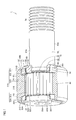
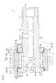
図1は、本開示の一実施の形態におけるフォロア軸受の構造を示す概略斜視図である。図1においては、内部の構造を表示する観点から、一部の部品を部分的に切断した状態が示されている。図1において、ハッチングが付された領域は、断面に対応する。図2は、フォロア軸受の構造を示す概略断面図である。図2は、フォロア軸受の回転軸を含む断面を示す。図3は、図2の領域αを拡大して示す概略断面図である。
FIG. 1 is a schematic perspective view showing the structure of the follower bearing according to the embodiment of the present disclosure. In FIG. 1, a state in which some parts are partially cut is shown from the viewpoint of displaying the internal structure. In FIG. 1, the hatched region corresponds to a cross section. FIG. 2 is a schematic cross-sectional view showing the structure of the follower bearing. FIG. 2 shows a cross section including the rotation axis of the follower bearing. FIG. 3 is a schematic cross-sectional view showing an enlarged region α of FIG.
図1~図3を参照して、本実施の形態におけるフォロア軸受1は、内方部材10と、外輪20と、第1シール部材30Aと、第2シール部材30Bと、転動体としての複数のころ40と、を備えている。本実施の形態では、フォロア軸受1は、ころ40の保持器を有さない総ころ軸受である。内方部材10は、第1本体部50と、第1本体部50の一方の端部の外周面に配置される鍔部52と、リング60と、を含む。内方部材10は、鋼製である。第1本体部50は、棒状(中実円筒状)の形状を有する。
With reference to FIGS. 1 to 3, the follower bearing 1 in the present embodiment includes an inner member 10, an outer ring 20, a first seal member 30A, a second seal member 30B, and a plurality of rolling elements. It is equipped with a roller 40. In the present embodiment, the follower bearing 1 is a full roller bearing that does not have a cage for the rollers 40. The inner member 10 includes a first main body portion 50, a flange portion 52 arranged on the outer peripheral surface of one end of the first main body portion 50, and a ring 60. The inner member 10 is made of steel. The first main body portion 50 has a rod-like (solid cylindrical shape) shape.
第1本体部50の一方の端部の、第1本体部50の中心軸と交差(本実施の形態では直交)する領域を含むように、正六角柱状の形状を有する六角穴53Aが形成されている。第1本体部50の他方の端部の外周面には、らせん状のねじ溝が形成されたねじ部54が配置されている。このような構造を有することにより、フォロア軸受1の設置に際しては、例えばフォロア軸受1を保持する保持部材に形成されたねじ穴(図示せず)にねじ部54をねじ込むとともに、六角穴53Aに六角レンチの先端を挿入して締めつける、またはハウジング孔に内方部材10を通し、ねじ部54にナットを螺合することにより、保持部材に対してフォロア軸受1を固定することができる。
A hexagonal hole 53A having a regular hexagonal columnar shape is formed so as to include a region of one end of the first main body 50 that intersects the central axis of the first main body 50 (orthogonal in the present embodiment). ing. A threaded portion 54 having a spiral threaded groove is arranged on the outer peripheral surface of the other end of the first main body portion 50. By having such a structure, when installing the follower bearing 1, for example, the screw portion 54 is screwed into a screw hole (not shown) formed in the holding member holding the follower bearing 1, and the hexagonal hole 53A is hexagonal. The follower bearing 1 can be fixed to the holding member by inserting and tightening the tip of the wrench, or by passing the inner member 10 through the housing hole and screwing the nut into the screw portion 54.
第1本体部50は、他の領域よりも径がやや大きい大径部51を有する。大径部51は、軸方向において中央よりも鍔部52側に配置されている。大径部51は、軸方向において後述する鍔部52とねじ部54との間に配置されている。大径部51の外周面は、円筒面状の形状を有する第1転走面51Aを含む。すなわち、第1本体部50は、円環状の第1転走面51Aを外周面50Aに有している。
The first main body portion 50 has a large diameter portion 51 having a diameter slightly larger than that of other regions. The large diameter portion 51 is arranged closer to the collar portion 52 than the center in the axial direction. The large diameter portion 51 is arranged between the flange portion 52 and the screw portion 54, which will be described later, in the axial direction. The outer peripheral surface of the large diameter portion 51 includes a first rolling surface 51A having a cylindrical surface shape. That is, the first main body 50 has an annular first rolling surface 51A on the outer peripheral surface 50A.
第1本体部50には、軸方向において鍔部52とは反対側の端部に開口56Aを有し、軸方向に沿って延びる第1の穴56が形成されている。第1本体部50には、第1本体部50の外周面50Aに開口57Aを有し、径方向に沿って延びる第2の穴57が形成されている。第2の穴57は、第1の穴56に連通する。第1本体部50には、大径部51の第1転走面51Aに開口58Aを有し、径方向に沿って延びる第3の穴58が形成されている。第3の穴58は、第1の穴56に連通する。第1本体部50は、軸方向において大径部51とねじ部54との間に配置され、大径部51よりも径の小さい円環状の突出部501を有する。
The first main body 50 has an opening 56A at an end opposite to the flange 52 in the axial direction, and a first hole 56 extending along the axial direction is formed. The first main body 50 has an opening 57A on the outer peripheral surface 50A of the first main body 50, and a second hole 57 extending along the radial direction is formed. The second hole 57 communicates with the first hole 56. The first main body portion 50 has an opening 58A in the first rolling surface 51A of the large diameter portion 51, and a third hole 58 extending along the radial direction is formed. The third hole 58 communicates with the first hole 56. The first main body portion 50 is arranged between the large diameter portion 51 and the threaded portion 54 in the axial direction, and has an annular protruding portion 501 having a diameter smaller than that of the large diameter portion 51.
鍔部52は、第1本体部50よりも径の大きい円盤環状の形状を有する。鍔部52は、第1本体部50と同軸の中心軸を有する。大径部51の径は、鍔部52の径よりも小さい。鍔部52は、外周面52Aと、軸方向における一方の端面である第1端面52Bと、第1端面52Bとは反対側の第2端面52Cと、を含む。第1端面52Bと、第2端面52Cとは平行に配置される。第1端面52Bおよび第2端面52Cは、平面状の形状を有する。本実施の形態では、第2端面52Cの最大高さ粗さRzは12.5μm以下である。第2端面52Cの最大高さ粗さRzは、好ましくは8μm以下であり、さらに好ましくは7μm以下であり、特に好ましくは6.3μm以下である。最大高さ粗さRzは、例えばJIS B 0601に基づいて測定することができる。本実施の形態では、例えば、鍔部52の第2端面52Cに対して研削加工を実施することで、上記最大高さ粗さRzを満たす第2端面52Cを有する鍔部52を形成することができる。なお、第2端面52Cは、上記最大高さ粗さRzを満たすように、研削加工の他、公知の方法によって加工されてもよい。
The collar portion 52 has a disk ring shape having a diameter larger than that of the first main body portion 50. The collar portion 52 has a central axis coaxial with the first main body portion 50. The diameter of the large diameter portion 51 is smaller than the diameter of the flange portion 52. The flange portion 52 includes an outer peripheral surface 52A, a first end surface 52B which is one end surface in the axial direction, and a second end surface 52C opposite to the first end surface 52B. The first end surface 52B and the second end surface 52C are arranged in parallel. The first end surface 52B and the second end surface 52C have a planar shape. In the present embodiment, the maximum height roughness Rz of the second end surface 52C is 12.5 μm or less. The maximum height roughness Rz of the second end surface 52C is preferably 8 μm or less, more preferably 7 μm or less, and particularly preferably 6.3 μm or less. The maximum height roughness Rz can be measured based on, for example, JIS B 0601. In the present embodiment, for example, by performing grinding on the second end surface 52C of the flange portion 52, the collar portion 52 having the second end surface 52C satisfying the maximum height roughness Rz can be formed. can. The second end surface 52C may be processed by a known method in addition to the grinding process so as to satisfy the maximum height roughness Rz.
リング60は、軸方向において、第1本体部50の大径部51から見て、鍔部52とは反対側の突出部501の外周面に嵌め込まれている。リング60は、突出部501の外周面に公知の方法で固定されている。リング60は、円環状の形状を有する。リング60は、外周面61と、内周面62と、軸方向における一方の端面である第3端面63と、第3端面63とは反対側の第4端面64と、を含む。外周面61と、内周面62とは同心の円筒面である。第3端面63と、第4端面64とは平行に配置される。図3を参照して、軸方向における大径部51の鍔部52とは反対側の段差部である段差面51Bに第3端面63において接触するように、リング60が配置される。リング60は、第1本体部50に圧入され、第1本体部50に対して固定されている。本実施の形態では、リング60の第3端面63の最大高さ粗さRzは12.5μm以下である。第3端面63の最大高さ粗さRzは、好ましくは8μm以下であり、さらに好ましくは7μm以下であり、特に好ましくは、6.3μm以下である。最大高さ粗さRzは、例えばJIS B 0601に基づいて測定することができる。本実施の形態では、例えば、リング60の第3端面63に対して研削加工を実施することで、上記最大高さ粗さRzを満たす第3端面63を有するリング60を作製することができる。軸方向において大径部51を挟むように鍔部52とリング60とが配置されることで、軸方向に外輪20および複数のころ40が軸方向に抜けてしまうことを抑制することができる。なお、第3端面63は、上記最大高さ粗さRzを満たすように、研削加工の他、公知の方法によって加工されてもよい。
The ring 60 is fitted on the outer peripheral surface of the protruding portion 501 on the opposite side of the flange portion 52 when viewed from the large diameter portion 51 of the first main body portion 50 in the axial direction. The ring 60 is fixed to the outer peripheral surface of the protrusion 501 by a known method. The ring 60 has an annular shape. The ring 60 includes an outer peripheral surface 61, an inner peripheral surface 62, a third end surface 63 which is one end surface in the axial direction, and a fourth end surface 64 opposite to the third end surface 63. The outer peripheral surface 61 and the inner peripheral surface 62 are concentric cylindrical surfaces. The third end surface 63 and the fourth end surface 64 are arranged in parallel. With reference to FIG. 3, the ring 60 is arranged so as to come into contact with the stepped surface 51B, which is the stepped portion on the side opposite to the flange portion 52 of the large diameter portion 51 in the axial direction, at the third end surface 63. The ring 60 is press-fitted into the first main body 50 and is fixed to the first main body 50. In the present embodiment, the maximum height roughness Rz of the third end surface 63 of the ring 60 is 12.5 μm or less. The maximum height roughness Rz of the third end surface 63 is preferably 8 μm or less, more preferably 7 μm or less, and particularly preferably 6.3 μm or less. The maximum height roughness Rz can be measured based on, for example, JIS B 0601. In the present embodiment, for example, by performing a grinding process on the third end surface 63 of the ring 60, a ring 60 having the third end surface 63 satisfying the above maximum height roughness Rz can be produced. By arranging the flange portion 52 and the ring 60 so as to sandwich the large diameter portion 51 in the axial direction, it is possible to prevent the outer ring 20 and the plurality of rollers 40 from coming off in the axial direction. The third end surface 63 may be processed by a known method in addition to the grinding process so as to satisfy the maximum height roughness Rz.
内方部材10は、機械構造用炭素鋼、機械構造用合金鋼、軸受鋼などの鋼からなる。本実施の形態では、内方部材10は、高炭素クロム軸受鋼製である。第1本体部50の第1転走面51Aを含む領域に対して、熱処理が実施されてもよい。熱処理として、例えば、高周波焼入および焼戻が実施されてもよい。第1本体部50の第1転走面51Aを含む領域に対して、研削加工が実施されてもよい。本実施の形態では、鍔部52に対しては、熱処理が実施されない。
The inner member 10 is made of steel such as carbon steel for machine structure, alloy steel for machine structure, and bearing steel. In this embodiment, the inner member 10 is made of high carbon chrome bearing steel. A heat treatment may be performed on the region of the first main body 50 including the first rolling surface 51A. As the heat treatment, for example, induction hardening and tempering may be performed. Grinding may be performed on the region including the first rolling surface 51A of the first main body 50. In the present embodiment, the collar portion 52 is not heat-treated.
外輪20は、内周面21Aと、外周面21Bと、軸方向の一方の端面である第1外輪端面21Cと、軸方向の他方の端面である第2外輪端面21Dと、を含む。内周面21Aは、第1本体部50の第1転走面51Aに対向する第2転走面22Cを含む。すなわち、外輪20は、第2転走面22Cを内周面21Aに有する。第2転走面22Cは、円筒面状の形状を有する。本実施の形態では、外周面21Bは、円筒面状の形状を有する。第1外輪端面21Cおよび第2外輪端面21Dは、環状の平面である。第1外輪端面21Cおよび第2外輪端面21Dは、軸方向に直交する。第1外輪端面21Cと第2外輪端面21Dとは平行に配置される。第1外輪端面21Cおよび第2外輪端面21Dは、フォロア軸受1において、外部に露出する構成である。
The outer ring 20 includes an inner peripheral surface 21A, an outer peripheral surface 21B, a first outer ring end surface 21C which is one end surface in the axial direction, and a second outer ring end surface 21D which is the other end surface in the axial direction. The inner peripheral surface 21A includes a second rolling surface 22C facing the first rolling surface 51A of the first main body 50. That is, the outer ring 20 has a second rolling surface 22C on the inner peripheral surface 21A. The second rolling surface 22C has a cylindrical surface shape. In the present embodiment, the outer peripheral surface 21B has a cylindrical surface shape. The first outer ring end surface 21C and the second outer ring end surface 21D are annular planes. The first outer ring end surface 21C and the second outer ring end surface 21D are orthogonal to each other in the axial direction. The first outer ring end surface 21C and the second outer ring end surface 21D are arranged in parallel. The first outer ring end surface 21C and the second outer ring end surface 21D are configured to be exposed to the outside in the follower bearing 1.
内周面21Aは、軸方向において、第2転走面22Cを挟むように配置される円環状の第1の面22Aおよび円環状の第3の面22Dを含む。第1の面22Aは、外輪20の一方の端部の内周面21Aに配置される。第3の面22Dは、外輪20の他方の端部の内周面21Aに配置される。第1の面22Aおよび第3の面22Dの直径は、第2転走面22Cの直径よりも大きい。第1の面22Aおよび第3の面22Dは、回転軸と同軸の中心軸を有する円筒面状の形状を有する。第1の面22Aは、鍔部52の外周面52Aに対向する。第3の面22Dは、リング60の外周面61に対向する。内周面21Aは、第1の面22Aと第2転走面22Cとをつなぐ第2の面22Bと、第3の面22Dと第2転走面22Cとをつなぐ第4の面22Eとをさらに含む。第2の面22Bおよび第4の面22Eは、環状の平面である。第2の面22Bおよび第4の面22Eは、軸方向に直交する。第2の面22Bと第4の面22Eとは平行に配置される。第2の面22Bは、鍔部52の第2端面52Cに対向する。第4の面22Eは、リング60の第3端面63に対向する。
The inner peripheral surface 21A includes an annular first surface 22A and an annular third surface 22D arranged so as to sandwich the second rolling surface 22C in the axial direction. The first surface 22A is arranged on the inner peripheral surface 21A of one end of the outer ring 20. The third surface 22D is arranged on the inner peripheral surface 21A of the other end of the outer ring 20. The diameter of the first surface 22A and the third surface 22D is larger than the diameter of the second rolling surface 22C. The first surface 22A and the third surface 22D have a cylindrical surface shape having a central axis coaxial with the rotation axis. The first surface 22A faces the outer peripheral surface 52A of the flange portion 52. The third surface 22D faces the outer peripheral surface 61 of the ring 60. The inner peripheral surface 21A includes a second surface 22B connecting the first surface 22A and the second rolling surface 22C, and a fourth surface 22E connecting the third surface 22D and the second rolling surface 22C. Including further. The second surface 22B and the fourth surface 22E are annular planes. The second surface 22B and the fourth surface 22E are orthogonal to each other in the axial direction. The second surface 22B and the fourth surface 22E are arranged in parallel. The second surface 22B faces the second end surface 52C of the flange portion 52. The fourth surface 22E faces the third end surface 63 of the ring 60.
外輪20は、機械構造用炭素鋼、機械構造用合金鋼、軸受鋼などの鋼からなる。本実施の形態では、外輪20は、高炭素クロム軸受鋼製である。外輪20の第2転走面22Cを含む領域に対して、熱処理が実施されてもよい。熱処理として、例えば、高周波焼入および焼戻が実施されてもよい。第2転走面22Cを含む領域に対して、研削加工が実施されてもよい。
The outer ring 20 is made of steel such as carbon steel for machine structure, alloy steel for machine structure, and bearing steel. In this embodiment, the outer ring 20 is made of high carbon chrome bearing steel. Heat treatment may be performed on the region including the second rolling surface 22C of the outer ring 20. As the heat treatment, for example, induction hardening and tempering may be performed. Grinding may be performed on the region including the second rolling surface 22C.
図2~図4を参照して、第1シール部材30Aおよび第2シール部材30Bは、第1部分および第3部分としての環状部31と、第2部分および第4部分としての突出部32と、を含む。環状部31は、円環状の形状を有する。環状部31は、外周面31Aと内周面31Bとを含む。外周面31Aは、円錐面状の形状を有する。内周面31Bは、円筒面状の形状を有する。外周面31Aおよび内周面31Bは、回転軸と同軸の中心軸を有する。環状部31の外周面31Aは、一方の端面に向かって径が大きくなるテーパ状の形状を有する。環状部31の外径は、第1の面22Aおよび第3の面22Dの内径よりも小さい。突出部32は、環状部31に接続される。突出部32は、環状部31の他方の端面から径方向内側に沿って突出する。突出部32は、円環状の形状を有する。突出部32は、平板環状の形状を有する。突出部32は、環状部31と同軸に配置される。突出部32は、軸方向における一方の端面32Aと、端面32Aとは反対側の端面32Bとを含む。
With reference to FIGS. 2 to 4, the first seal member 30A and the second seal member 30B have an annular portion 31 as a first portion and a third portion and a protruding portion 32 as a second portion and a fourth portion. ,including. The annular portion 31 has an annular shape. The annular portion 31 includes an outer peripheral surface 31A and an inner peripheral surface 31B. The outer peripheral surface 31A has a conical surface shape. The inner peripheral surface 31B has a cylindrical surface shape. The outer peripheral surface 31A and the inner peripheral surface 31B have a central axis coaxial with the rotation axis. The outer peripheral surface 31A of the annular portion 31 has a tapered shape whose diameter increases toward one end surface. The outer diameter of the annular portion 31 is smaller than the inner diameter of the first surface 22A and the third surface 22D. The protruding portion 32 is connected to the annular portion 31. The protruding portion 32 protrudes inward in the radial direction from the other end face of the annular portion 31. The protrusion 32 has an annular shape. The protrusion 32 has a flat plate annular shape. The protruding portion 32 is arranged coaxially with the annular portion 31. The protrusion 32 includes one end face 32A in the axial direction and an end face 32B opposite to the end face 32A.
図3を参照して、第1シール部材30Aの環状部31は、径方向において鍔部52の外周面52Aと第1の面22Aとの間に配置されている。第1シール部材30Aの環状部31の外周面31Aと第1の面22Aとの間には、隙間が形成されている。なお、環状部31と鍔部52の外周面52Aとの間には、図示していない隙間が形成されている。環状部31は鍔部52に隙間嵌されている。第1シール部材30Aは、いわゆる非接触シールである。第1シール部材30Aにおける突出部32は、軸方向において鍔部52の第2端面52Cと第2の面22Bとの間に配置されている。突出部32の端面32Aは、鍔部52の第2端面52Cに接触可能である。突出部32の端面32Bは、軸方向において第2の面22Bに対向する。第1シール部材30Aと外輪20との間に隙間を形成すると共に、第1シール部材30Aと鍔部52との間に隙間を形成することにより、第1シール部材30Aを設置することによる外輪20の摺動抵抗や回転トルクなどの増加を低減することができ、外輪20をスムーズに回転させることができる。なお、外周面31Aと第1の面22Aとを接触させ、隙間を形成しない構造としてもよい。また、鍔部52と第1シール部材30Aとは隙間のない密着した構造としてもよい。
With reference to FIG. 3, the annular portion 31 of the first seal member 30A is arranged between the outer peripheral surface 52A and the first surface 22A of the flange portion 52 in the radial direction. A gap is formed between the outer peripheral surface 31A of the annular portion 31 of the first seal member 30A and the first surface 22A. A gap (not shown) is formed between the annular portion 31 and the outer peripheral surface 52A of the flange portion 52. The annular portion 31 is gap-fitted into the flange portion 52. The first seal member 30A is a so-called non-contact seal. The protruding portion 32 of the first seal member 30A is arranged between the second end surface 52C and the second surface 22B of the flange portion 52 in the axial direction. The end surface 32A of the protruding portion 32 can come into contact with the second end surface 52C of the flange portion 52. The end surface 32B of the protrusion 32 faces the second surface 22B in the axial direction. The outer ring 20 by installing the first seal member 30A by forming a gap between the first seal member 30A and the outer ring 20 and forming a gap between the first seal member 30A and the flange portion 52. It is possible to reduce the increase in the sliding resistance and the rotational torque of the outer ring 20, and the outer ring 20 can be rotated smoothly. The outer peripheral surface 31A and the first surface 22A may be brought into contact with each other to form no gap. Further, the flange portion 52 and the first seal member 30A may have a structure in which they are in close contact with each other without a gap.
第2シール部材30Bの環状部31は、径方向においてリング60の外周面61と第3の面22Dとの間に配置されている。第2シール部材30Bの環状部31の外周面31Aと第3の面22Dとの間には、隙間が形成されている。なお、環状部31とリング60の外周面61との間には、図示してしない隙間が形成されている。環状部31はリング60に隙間嵌されている。第2シール部材30Bは、いわゆる非接触シールである。第2シール部材30Bにおける突出部32は、軸方向においてリング60の第3端面63と第4の面22Eとの間に配置されている。突出部32の端面32Aは、リング60の第3端面63に接触可能である。突出部32の端面32Bは、軸方向において第4の面22Eに対向する。第2シール部材30Bと外輪20との間に隙間を形成すると共に、第2シール部材30Bとリング60との間に隙間を形成することにより、第2シール部材30Bを設置することによる外輪20の摺動抵抗や回転トルクなどの増加を低減することができ、外輪20をスムーズに回転させることができる。なお、外周面61と第3の面22Dとを接触させ、隙間を形成しない構造としてもよい。また、リング60と第2シール部材30Bとは隙間のない密着した構造としてもよい。
The annular portion 31 of the second seal member 30B is arranged between the outer peripheral surface 61 of the ring 60 and the third surface 22D in the radial direction. A gap is formed between the outer peripheral surface 31A and the third surface 22D of the annular portion 31 of the second seal member 30B. A gap (not shown) is formed between the annular portion 31 and the outer peripheral surface 61 of the ring 60. The annular portion 31 is gap-fitted in the ring 60. The second seal member 30B is a so-called non-contact seal. The protrusion 32 of the second seal member 30B is arranged between the third end surface 63 and the fourth surface 22E of the ring 60 in the axial direction. The end face 32A of the protrusion 32 can come into contact with the third end face 63 of the ring 60. The end surface 32B of the protrusion 32 faces the fourth surface 22E in the axial direction. By forming a gap between the second seal member 30B and the outer ring 20 and forming a gap between the second seal member 30B and the ring 60, the outer ring 20 is provided by installing the second seal member 30B. It is possible to reduce an increase in sliding resistance, rotational torque, etc., and the outer ring 20 can be rotated smoothly. The outer peripheral surface 61 and the third surface 22D may be brought into contact with each other to form no gap. Further, the ring 60 and the second seal member 30B may have a structure in which they are in close contact with each other without a gap.
第1シール部材30Aの環状部31は、軸方向において第1端面52B側に位置する第1シール端面31Cを含む。第2シール部材30Bの環状部31は、軸方向において第4端面64側に位置する第2シール端面31Dを含む。第1シール端面31Cおよび第2シール端面31Dは、環状の平面である。第1シール端面31Cおよび第2シール端面31Dは、軸方向に直交する。第1シール端面31Cと第2シール端面31Dとは平行に配置される。第1シール端面31Cは、軸方向において第1外輪端面21Cよりも軸受内部側に配置される。本実施形態においては、外輪20の第1の面22Aと鍔部52の外周面52Aと第1シール部材30Aの第1シール端面31Cとによって、軸方向に開口を有するスペース71が形成される。第2シール端面31Dは、軸方向において第2外輪端面21Dよりも軸受内部側に配置される。本実施形態においては、外輪20の第3の面22Dとリング60の外周面61と第2シール部材30Bの第2シール端面31Dとによって、軸方向に開口を有するスペース72が形成される。
The annular portion 31 of the first seal member 30A includes the first seal end surface 31C located on the first end surface 52B side in the axial direction. The annular portion 31 of the second seal member 30B includes a second seal end surface 31D located on the fourth end surface 64 side in the axial direction. The first seal end face 31C and the second seal end face 31D are annular flat surfaces. The first seal end face 31C and the second seal end face 31D are orthogonal to each other in the axial direction. The first seal end face 31C and the second seal end face 31D are arranged in parallel. The first seal end surface 31C is arranged on the inner side of the bearing with respect to the first outer ring end surface 21C in the axial direction. In the present embodiment, the first surface 22A of the outer ring 20, the outer peripheral surface 52A of the flange 52, and the first seal end surface 31C of the first seal member 30A form a space 71 having an opening in the axial direction. The second seal end face 31D is arranged on the inner side of the bearing with respect to the second outer ring end face 21D in the axial direction. In the present embodiment, the third surface 22D of the outer ring 20, the outer peripheral surface 61 of the ring 60, and the second seal end surface 31D of the second seal member 30B form a space 72 having an opening in the axial direction.
第1シール部材30Aおよび第2シール部材30Bを構成する材料は、ポリエーテルエーテルケトン、ポリアセタールおよびポリアミドからなる群から選択される少なくとも1つの樹脂である。本実施の形態では、第1シール部材30Aおよび第2シール部材30Bを構成する材料は、例えばナイロン66である。第1シール部材30Aおよび第2シール部材30Bを構成する材料は、二硫化モリブデンが添加されたナイロン66等でもよい。ナイロン66の他、二硫化モリブデン等を含んでいてもよい。第1シール部材30Aおよび第2シール部材30Bを構成する材料として、ナイロン66を採用すると、第1シール部材30Aおよび第2シール部材30Bが柔らかく、摩耗し易くなる。第2端面52Cおよび第3端面63の最大高さ粗さRzを6.3μm以下とすることで、第1シール部材30A及び第2シール部材30Bの摩耗を一層低減することができる。
The material constituting the first sealing member 30A and the second sealing member 30B is at least one resin selected from the group consisting of polyetheretherketone, polyacetal and polyamide. In the present embodiment, the material constituting the first seal member 30A and the second seal member 30B is, for example, nylon 66. The material constituting the first sealing member 30A and the second sealing member 30B may be nylon 66 or the like to which molybdenum disulfide is added. In addition to nylon 66, molybdenum disulfide and the like may be contained. When nylon 66 is used as the material constituting the first seal member 30A and the second seal member 30B, the first seal member 30A and the second seal member 30B are soft and easily worn. By setting the maximum height roughness Rz of the second end surface 52C and the third end surface 63 to 6.3 μm or less, the wear of the first seal member 30A and the second seal member 30B can be further reduced.
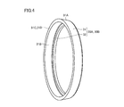
図2~図4を参照して、複数のころ40が、第1転走面51Aおよび第2転走面22C上を転動可能に配置されている。ころ40は、中実円筒状の形状を有する。ころ40は、円筒面状の外周面41と、球面状の一対の端面42とを含む。端面42は、平坦状であってもよい。ころ40は、外周面41において第1転走面51Aおよび第2転走面22Cに接触している。ころ40は、例えば軸受鋼などの鋼からなっている。ころ40は、焼入硬化されていてもよい。
With reference to FIGS. 2 to 4, a plurality of rollers 40 are arranged so as to be rollable on the first rolling surface 51A and the second rolling surface 22C. The roller 40 has a solid cylindrical shape. The roller 40 includes a cylindrical outer peripheral surface 41 and a pair of spherical end surfaces 42. The end face 42 may be flat. The rollers 40 are in contact with the first rolling surface 51A and the second rolling surface 22C on the outer peripheral surface 41. The roller 40 is made of steel such as bearing steel. The roller 40 may be quench-hardened.
次に、本実施の形態におけるフォロア軸受1の組立方法について説明する。まず、図5を参照して、第1本体部50と、鍔部52とを含む中間体2が準備される。次に、図5および図6を参照して、中間体2に対して第1シール部材30Aが取り付けられる。第1本体部50の端部55を第1シール部材30Aに挿入し、第1シール部材30Aの突出部32が鍔部52の第2端面52Cに接触するように配置される。次に、図6および図7を参照して、第1シール部材30Aが設置された中間体2に対して、ころ40が配置される。この際に、ころ40は、外周面41において第1転走面51Aに接触するように配置される。次に、図7および図8を参照して、第1シール部材30Aが取り付けられ、ころ40が配置された中間体2に対して、外輪20が取り付けられる。第1本体部50の端部55を外輪20に挿入し、外輪20の第2転走面22Cがころ40の外周面41に接触すると共に第1転走面51Aに対向するように配置される。次に、図2、図3および図8を参照して、第1シール部材30Aおよび外輪20が取り付けられ、ころ40が配置された中間体2に対して、第2シール部材30Bが設置されたリング60が取り付けられる。第1本体部50の端部55がリング60に挿入され、リング60が大径部51の段差面51Bに接触するように嵌め込まれることにより、リング60は第1本体部50に固定される。以上の工程により、本実施の形態のフォロア軸受1が完成する。
Next, the method of assembling the follower bearing 1 in the present embodiment will be described. First, referring to FIG. 5, an intermediate 2 including a first main body portion 50 and a collar portion 52 is prepared. Next, with reference to FIGS. 5 and 6, the first seal member 30A is attached to the intermediate body 2. The end portion 55 of the first main body portion 50 is inserted into the first seal member 30A, and the protruding portion 32 of the first seal member 30A is arranged so as to come into contact with the second end surface 52C of the flange portion 52. Next, with reference to FIGS. 6 and 7, the rollers 40 are arranged with respect to the intermediate body 2 in which the first seal member 30A is installed. At this time, the rollers 40 are arranged so as to come into contact with the first rolling surface 51A on the outer peripheral surface 41. Next, with reference to FIGS. 7 and 8, the first seal member 30A is attached, and the outer ring 20 is attached to the intermediate body 2 in which the rollers 40 are arranged. The end 55 of the first main body 50 is inserted into the outer ring 20, and the second rolling surface 22C of the outer ring 20 is arranged so as to come into contact with the outer peripheral surface 41 of the roller 40 and face the first rolling surface 51A. .. Next, with reference to FIGS. 2, 3 and 8, the first seal member 30A and the outer ring 20 were attached, and the second seal member 30B was installed with respect to the intermediate body 2 in which the rollers 40 were arranged. The ring 60 is attached. The ring 60 is fixed to the first main body 50 by inserting the end 55 of the first main body 50 into the ring 60 and fitting the ring 60 into contact with the stepped surface 51B of the large diameter portion 51. By the above steps, the follower bearing 1 of the present embodiment is completed.
ここで、本実施の形態におけるフォロア軸受1は、第1シール部材30Aを備える。第1シール部材30Aは、外輪20との間にシール構造を形成する環状部31を含む。環状部31は、第1端面52B側に近付くにしたがって外径が大きくなる形状を有する。第1シール部材30Aが環状部31を含むことで、内方部材10に対して外輪20を取り付ける際に外輪20が環状部31によって案内され、外輪20が第1シール部材30Aに引っ掛かることが低減される。したがって、本実施の形態におけるフォロア軸受1によれば、フォロア軸受1の組み立てが容易である。
Here, the follower bearing 1 in the present embodiment includes the first seal member 30A. The first seal member 30A includes an annular portion 31 that forms a seal structure with the outer ring 20. The annular portion 31 has a shape in which the outer diameter increases as it approaches the first end surface 52B side. Since the first seal member 30A includes the annular portion 31, the outer ring 20 is guided by the annular portion 31 when the outer ring 20 is attached to the inner member 10, and the outer ring 20 is less likely to be caught by the first seal member 30A. Will be done. Therefore, according to the follower bearing 1 in the present embodiment, the follower bearing 1 can be easily assembled.
本実施の形態では、第1シール部材30Aの環状部31は、第1端面52B側に近づくにしたがって外径が大きくなるテーパ状である。よって、内方部材10を外輪20に挿入する際に、外輪20が第1シール部材30Aの環状部31によってより確実に案内され、外輪20が第1シール部材30Aに引っ掛かることがより低減される。したがって、本開示のフォロア軸受1によれば、フォロア軸受1の組み立てをより容易にすることができる。
In the present embodiment, the annular portion 31 of the first seal member 30A has a tapered shape in which the outer diameter increases as it approaches the first end surface 52B side. Therefore, when the inner member 10 is inserted into the outer ring 20, the outer ring 20 is more reliably guided by the annular portion 31 of the first seal member 30A, and the outer ring 20 is less likely to be caught by the first seal member 30A. .. Therefore, according to the follower bearing 1 of the present disclosure, the follower bearing 1 can be more easily assembled.
上記実施の形態では、第1シール部材30Aは、突出部32を含む。第1シール部材30Aが突出部32を含むことで、フォロア軸受1に対しミスアライメントなどによって発生するアキシャル荷重が加わった際に、鍔部52の第2端面52Cと外輪20の第2の面22Bとが接触することを抑制することができる。したがって、鍔部52の第2端面52Cと外輪20の第2の面22Bとが接触することによる摩耗などの発生を抑制することができる。
In the above embodiment, the first seal member 30A includes a protruding portion 32. When the first seal member 30A includes the protruding portion 32 and an axial load generated by misalignment or the like is applied to the follower bearing 1, the second end surface 52C of the flange portion 52 and the second surface 22B of the outer ring 20 It is possible to suppress contact with. Therefore, it is possible to suppress the occurrence of wear and the like due to the contact between the second end surface 52C of the flange portion 52 and the second surface 22B of the outer ring 20.
上記実施の形態では、鍔部52の第2端面52Cの最大高さ粗さRzが、12.5μm以下である。このような構成を採用することで、フォロア軸受1に対しアキシャル荷重が加わった際に、第1シール部材30Aと鍔部52の第2端面52Cとの摩擦を低減することができる。
In the above embodiment, the maximum height roughness Rz of the second end surface 52C of the collar portion 52 is 12.5 μm or less. By adopting such a configuration, it is possible to reduce the friction between the first seal member 30A and the second end surface 52C of the flange portion 52 when an axial load is applied to the follower bearing 1.
上記実施の形態では、鍔部52の第2端面52Cおよびリング60の第3端面63に対して研削加工が実施される。上記実施の形態では、外輪20の第2の面22Bおよび第4の面22Eに対して、研削加工が実施されていない。すなわち、第2の面22Bおよび第4の面22Eの最大高さ粗さRzは、12.5μmよりも大きい。本実施の形態では、フォロア軸受1に対しアキシャル荷重が加わった際に、第1シール部材30Aが第2の面22Bに接触する面積が、第1シール部材30Aが第2端面52Cに接触する面積よりも大きくなっている。つまり、第1シール部材30Aと外輪20との間に発生する摩擦力は、第1シール部材30Aと鍔部52との間に発生する摩擦力よりも大きくなる。第1シール部材30Aと同様に、フォロア軸受1に対しアキシャル荷重が加わった際に、第2シール部材30Bが第4の面22Eに接触する面積が、第2シール部材30Bが第3端面63に接触する面積よりも大きくなっている。つまり、第2シール部材30Bと外輪20との間に発生する摩擦力は、第2シール部材30Bとリング60との間に発生する摩擦力よりも大きくなる。この際に、第1シール部材30Aまたは第2シール部材30Bが、外輪20と共に内方部材10に対して回転する場合がある。第1シール部材30Aまたは第2シール部材30Bが回転すると、第1シール部材30Aと第2端面52Cとの間、または第2シール部材30Bと第3端面63との間ですべり摩擦が発生し、第1シール部材30Aまたは第2シール部材30Bの摩耗が発生する。第2端面52Cおよび第3端面63の最大高さ粗さRzを小さくすることによって、上記すべり摩擦の発生を低減し、第1シール部材30Aおよび第2シール部材30Bの摩耗を低減することができる。なお、外輪20の第2の面22Bに対して、研削加工が実施されない場合について説明したが、これに限られず、外輪20の第2の面22Bに対して研削加工が実施されてもよい。
In the above embodiment, grinding is performed on the second end surface 52C of the flange portion 52 and the third end surface 63 of the ring 60. In the above embodiment, the second surface 22B and the fourth surface 22E of the outer ring 20 are not ground. That is, the maximum height roughness Rz of the second surface 22B and the fourth surface 22E is larger than 12.5 μm. In the present embodiment, when an axial load is applied to the follower bearing 1, the area where the first seal member 30A contacts the second surface 22B is the area where the first seal member 30A contacts the second end surface 52C. Is bigger than. That is, the frictional force generated between the first seal member 30A and the outer ring 20 is larger than the frictional force generated between the first seal member 30A and the flange portion 52. Similar to the first seal member 30A, when an axial load is applied to the follower bearing 1, the area where the second seal member 30B contacts the fourth surface 22E is such that the second seal member 30B is on the third end surface 63. It is larger than the contact area. That is, the frictional force generated between the second seal member 30B and the outer ring 20 is larger than the frictional force generated between the second seal member 30B and the ring 60. At this time, the first seal member 30A or the second seal member 30B may rotate with respect to the inner member 10 together with the outer ring 20. When the first seal member 30A or the second seal member 30B rotates, slip friction occurs between the first seal member 30A and the second end surface 52C, or between the second seal member 30B and the third end surface 63. Wear of the first seal member 30A or the second seal member 30B occurs. By reducing the maximum height roughness Rz of the second end surface 52C and the third end surface 63, it is possible to reduce the occurrence of the slip friction and reduce the wear of the first seal member 30A and the second seal member 30B. .. Although the case where the second surface 22B of the outer ring 20 is not subjected to the grinding process has been described, the present invention is not limited to this, and the second surface 22B of the outer ring 20 may be subjected to the grinding process.
上記実施の形態では、第1シール端面31Cは、軸方向において第1外輪端面21Cよりも軸受内部側に配置され、外輪20の第1の面22Aと鍔部52の外周面52Aと第1シール部材30Aの第1シール端面31Cとによって、軸方向に開口を有するスペース71が形成される構成を採用する。このようにすることにより、フォロア軸受1を構成する各部材の寸法の許容差が累積されたとしても、軸方向において第1外輪端面21Cよりも第1シール端面31Cが軸受外部側に突き出るおそれを低減することができる。よって、第1シール部材30Aの外周面31Aが軸受外部に露出するおそれを低減することができ、第1シール部材30Aの外周面31A上にダストを溜まりにくくすることができる。また、このような形状の第1シール部材30Aを樹脂成型する際に、角部が狭くなる箇所が少ないため、容易に成型することができる。
In the above embodiment, the first seal end surface 31C is arranged on the inner side of the bearing with respect to the first outer ring end surface 21C in the axial direction, and the first surface 22A of the outer ring 20 and the outer peripheral surface 52A and the first seal of the flange portion 52. A configuration is adopted in which a space 71 having an opening in the axial direction is formed by the first seal end surface 31C of the member 30A. By doing so, even if the dimensional tolerances of the members constituting the follower bearing 1 are accumulated, there is a possibility that the first seal end surface 31C protrudes to the outer side of the bearing rather than the first outer ring end surface 21C in the axial direction. It can be reduced. Therefore, it is possible to reduce the possibility that the outer peripheral surface 31A of the first seal member 30A is exposed to the outside of the bearing, and it is possible to prevent dust from accumulating on the outer peripheral surface 31A of the first seal member 30A. Further, when the first seal member 30A having such a shape is resin-molded, it can be easily molded because there are few places where the corners are narrowed.
上記実施の形態では、フォロア軸受1は、第2シール部材30Bを備える。第2シール部材30Bは、第1シール部材30Aと同様に環状部31および突出部32を含む。第2シール部材30Bの環状部31は、リング60の第4端面64側に近付くにしたがって外径が大きくなる形状を有する。第2シール部材30Bが環状部31を含むことで、第2シール部材30Bが設置されたリング60を第1本体部50に取り付ける際に、リング60が環状部31の外周面31Aによって案内され、第2シール部材30Bが外輪20に引っ掛かることが低減される。したがって、第2シール部材30Bが設置されたリング60を第1本体部50に対して取り付け易くすることができる。また、第2シール部材30Bが突出部32を含むことで、フォロア軸受1に対しアキシャル荷重が加わった際にリング60の第3端面63と第4の面22Eとが接触することを抑制することができる。したがって、リング60の第3端面63と外輪20の第4の面22Eとが接触することによる摩耗などの発生を抑制することができる。
In the above embodiment, the follower bearing 1 includes a second seal member 30B. The second seal member 30B includes an annular portion 31 and a protruding portion 32, similarly to the first seal member 30A. The annular portion 31 of the second seal member 30B has a shape in which the outer diameter increases as it approaches the fourth end surface 64 side of the ring 60. Since the second seal member 30B includes the annular portion 31, the ring 60 is guided by the outer peripheral surface 31A of the annular portion 31 when the ring 60 on which the second seal member 30B is installed is attached to the first main body portion 50. It is reduced that the second seal member 30B is caught on the outer ring 20. Therefore, the ring 60 on which the second seal member 30B is installed can be easily attached to the first main body 50. Further, since the second seal member 30B includes the protrusion 32, it is possible to prevent the third end surface 63 and the fourth surface 22E of the ring 60 from coming into contact with each other when an axial load is applied to the follower bearing 1. Can be done. Therefore, it is possible to suppress the occurrence of wear and the like due to the contact between the third end surface 63 of the ring 60 and the fourth surface 22E of the outer ring 20.
上記実施の形態では、第2シール部材30Bの環状部31は、第4端面64側に近づくにしたがって外径が大きくなるテーパ状である。よって、リング60を第1本体部50に取り付ける際に、リング60が第2シール部材30Bの環状部31によってより確実に案内され、第2シール部材30Bが外輪20に引っ掛かることがより低減される。したがって、本開示のフォロア軸受1によれば、フォロア軸受1の組み立てをより容易にすることができる。
In the above embodiment, the annular portion 31 of the second seal member 30B has a tapered shape in which the outer diameter increases as it approaches the fourth end surface 64 side. Therefore, when the ring 60 is attached to the first main body 50, the ring 60 is more reliably guided by the annular portion 31 of the second seal member 30B, and the second seal member 30B is less likely to be caught by the outer ring 20. .. Therefore, according to the follower bearing 1 of the present disclosure, the follower bearing 1 can be more easily assembled.
上記実施の形態では、第2シール端面31Dは、軸方向において第2外輪端面21Dよりも軸受内部側に配置され、外輪20の第3の面22Dとリング60の外周面61と第2シール部材30Bの第2シール端面31Dとによって、軸方向に開口を有するスペース72が形成される構成を採用する。このようにすることにより、フォロア軸受1を構成する各部材の寸法の許容差が累積されたとしても、軸方向において第2外輪端面21Dよりも第2シール端面31Dが軸受外部側に突き出るおそれを低減することができる。よって、第2シール部材30Bの外周面31Aが軸受外部に露出するおそれを低減することができ、第2シール部材30Bの外周面31A上にダストを溜まりにくくすることができる。また、このような形状の第2シール部材30Bを樹脂成型する際に、角部が狭くなる箇所が少ないため、容易に成型することができる。
In the above embodiment, the second seal end surface 31D is arranged on the inner side of the bearing with respect to the second outer ring end surface 21D in the axial direction, and the third surface 22D of the outer ring 20, the outer peripheral surface 61 of the ring 60, and the second seal member. A configuration is adopted in which a space 72 having an opening in the axial direction is formed by the second seal end surface 31D of 30B. By doing so, even if the dimensional tolerances of the members constituting the follower bearing 1 are accumulated, there is a possibility that the second seal end surface 31D protrudes to the outer side of the bearing rather than the second outer ring end surface 21D in the axial direction. It can be reduced. Therefore, it is possible to reduce the possibility that the outer peripheral surface 31A of the second seal member 30B is exposed to the outside of the bearing, and it is possible to prevent dust from accumulating on the outer peripheral surface 31A of the second seal member 30B. Further, when the second seal member 30B having such a shape is resin-molded, it can be easily molded because there are few places where the corners are narrowed.
上記実施の形態では、リング60の第3端面63の最大高さ粗さRzが、12.5μm以下である。このような構成を採用することで、フォロア軸受1に対しアキシャル荷重が加わった際に第2シール部材30Bとリング60の第3端面63との摩擦を低減することができる。なお、フォロア軸受1の用途に応じ、リング60の第3端面63の最大高さ粗さRzが12.5μmよりも大きくてもよい。
In the above embodiment, the maximum height roughness Rz of the third end surface 63 of the ring 60 is 12.5 μm or less. By adopting such a configuration, it is possible to reduce the friction between the second seal member 30B and the third end surface 63 of the ring 60 when an axial load is applied to the follower bearing 1. The maximum height roughness Rz of the third end surface 63 of the ring 60 may be larger than 12.5 μm depending on the application of the follower bearing 1.
上記実施の形態では、第1シール部材30Aの環状部31は、第1端面52B側に近づくにしたがって外径が大きくなるテーパ状であることとしたが、これに限られない。例えば、第1シール部材30Aの環状部31の外周面31Aは、図2および図3に示す断面、すなわち、フォロア軸受1の回転軸を含む断面において円弧状であって、第1端面52B側に近づくにしたがって外径が大きくなるようにしてもよい。具体的には、外周面31Aの径の大きくなっていく割合が、第1端面52B側に近づくにしたがって、小さくなるような円弧状であってもよいし、外周面31Aの径の大きくなっていく割合が、第1端面52B側に近づくにしたがって、大きくなるような円弧状であってもよい。さらに、第1シール部材30Aの環状部31の外周面31Aは、円弧状の領域とテーパ状の領域とを含む構成としてもよい。すなわち、第1シール部材30Aの環状部31の外周面31Aは、円弧状の領域とテーパ状の領域とが軸方向において連なって形成されてもよい。また、第1シール部材30Aの環状部31の外周面31Aは、曲面を含むよう構成されていてもよい。同様に、第2シール部材30Bの環状部31は、第4端面64側に近づくにしたがって外径が大きくなるテーパ状であることとしたが、これに限られず、例えば、第2シール部材30Bの環状部31の外周面31Aは、図2および図3に示す断面、すなわち、フォロア軸受1の回転軸を含む断面において円弧状であって、第4端面64側に近づくにしたがって外径が大きくなるようにしてもよい。以下に示す実施の形態についても同様である。
In the above embodiment, the annular portion 31 of the first seal member 30A has a tapered shape in which the outer diameter increases as it approaches the first end surface 52B side, but the present invention is not limited to this. For example, the outer peripheral surface 31A of the annular portion 31 of the first seal member 30A has an arc shape in the cross section shown in FIGS. 2 and 3, that is, the cross section including the rotation axis of the follower bearing 1, and is on the first end surface 52B side. The outer diameter may be increased as it gets closer. Specifically, the ratio of the diameter of the outer peripheral surface 31A increasing may be an arc shape that decreases as the diameter of the outer peripheral surface 31A increases toward the first end surface 52B side, or the diameter of the outer peripheral surface 31A increases. It may have an arcuate shape in which the ratio increases as it approaches the first end surface 52B side. Further, the outer peripheral surface 31A of the annular portion 31 of the first seal member 30A may be configured to include an arcuate region and a tapered region. That is, the outer peripheral surface 31A of the annular portion 31 of the first seal member 30A may be formed by connecting an arcuate region and a tapered region in the axial direction. Further, the outer peripheral surface 31A of the annular portion 31 of the first seal member 30A may be configured to include a curved surface. Similarly, the annular portion 31 of the second seal member 30B has a tapered shape in which the outer diameter increases as it approaches the fourth end surface 64 side, but the present invention is not limited to this, and for example, the second seal member 30B has a tapered shape. The outer peripheral surface 31A of the annular portion 31 has an arc shape in the cross section shown in FIGS. 2 and 3, that is, the cross section including the rotation axis of the follower bearing 1, and the outer diameter increases as it approaches the fourth end surface 64 side. You may do so. The same applies to the embodiments shown below.
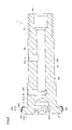
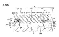
次に、他の実施の形態について説明する。図9は、他の実施の形態に係るフォロア軸受の構造を示す概略断面図である。図9は、フォロア軸受の回転軸を含む断面を示す。図10は、図9の領域αを拡大して示す概略断面図である。図9に示すフォロア軸受は、図1および図2に示すフォロア軸受に対して、第1シール部材および第2シール部材の構成が異なる点において、図1および図2に示すフォロア軸受と相違する。
Next, other embodiments will be described. FIG. 9 is a schematic cross-sectional view showing the structure of the follower bearing according to another embodiment. FIG. 9 shows a cross section including the rotation axis of the follower bearing. FIG. 10 is a schematic cross-sectional view showing an enlarged region α of FIG. The follower bearing shown in FIG. 9 is different from the follower bearing shown in FIGS. 1 and 2 in that the configurations of the first seal member and the second seal member are different from those shown in FIGS. 1 and 2.
図9および図10を参照して、他の実施の形態に係るフォロア軸受1は、第1シール部材30Cおよび第2シール部材30Dを含む。第1シール部材30Cは、第1シール部材30Aと同様に環状部31および突出部32を含む。第1シール部材30Cの環状部31の外周面31Aは、鍔部52の第1端面52B側に近づくにしたがって外径が大きくなるテーパ状の形状を有する。第1シール部材30Cは、軸方向において第1端面52B側に位置する第1シール端面31Eを含む。第1シール端面31Eは、第1端面52Bに近づくにしたがって外径が小さくなる形状を有する。具体的には、第1シール端面31Eは、第1端面52B側に近づくにしたがって外径が小さくなるテーパ状である。また、第1シール端面31Eは、軸方向において第1端面52Bに至るまで延びている。本実施形態においては、第1端面52Bには、いわゆるC面取りが施されているが、第1シール端面31Eは、C面取りが施された第1端面52Bに至るまで延びている。本実施形態においては、図2および図3に表れるスペース71は設けられない構成である。
With reference to FIGS. 9 and 10, the follower bearing 1 according to another embodiment includes a first seal member 30C and a second seal member 30D. The first seal member 30C includes an annular portion 31 and a protruding portion 32, similarly to the first seal member 30A. The outer peripheral surface 31A of the annular portion 31 of the first seal member 30C has a tapered shape in which the outer diameter increases as it approaches the first end surface 52B side of the flange portion 52. The first seal member 30C includes a first seal end surface 31E located on the first end surface 52B side in the axial direction. The first seal end face 31E has a shape in which the outer diameter becomes smaller as it approaches the first end face 52B. Specifically, the first seal end surface 31E has a tapered shape in which the outer diameter becomes smaller as it approaches the first end surface 52B side. Further, the first seal end surface 31E extends to the first end surface 52B in the axial direction. In the present embodiment, the first end surface 52B is chamfered with a so-called C, but the end surface 31E of the first seal extends to the first end surface 52B with a C chamfer. In the present embodiment, the space 71 shown in FIGS. 2 and 3 is not provided.
また、第2シール部材30Dは、第2シール部材30Bと同様に環状部31および突出部32を含む。第2シール部材30Dの環状部31の外周面31Aは、リング60の第4端面64側に近づくにしたがって外径が大きくなるテーパ状の形状を有する。第2シール部材30Dは、軸方向において第4端面64側に位置する第2シール端面31Fを含む。第2シール端面31Fは、第4端面64に近づくにしたがって外径が小さくなる形状を有する。具体的には、第2シール端面31Fは、第4端面64側に近づくにしたがって外径が小さくなるテーパ状である。なお、第2シール端面31Fについては、軸方向においてリング60の第4端面64には至っていない構成である。本実施形態においては、図2および図3に表れるスペース72は設けられない構成である。
Further, the second seal member 30D includes an annular portion 31 and a protruding portion 32, similarly to the second seal member 30B. The outer peripheral surface 31A of the annular portion 31 of the second seal member 30D has a tapered shape in which the outer diameter increases as it approaches the fourth end surface 64 side of the ring 60. The second seal member 30D includes a second seal end surface 31F located on the fourth end surface 64 side in the axial direction. The second seal end face 31F has a shape in which the outer diameter becomes smaller as it approaches the fourth end face 64. Specifically, the second seal end face 31F has a tapered shape in which the outer diameter becomes smaller as it approaches the fourth end face 64 side. The second seal end face 31F has a configuration that does not reach the fourth end face 64 of the ring 60 in the axial direction. In the present embodiment, the space 72 shown in FIGS. 2 and 3 is not provided.
上記実施の形態では、第1シール端面31E上にダストが溜まっても、第1シール端面31Eは上記形状を有するため、第1シール端面31E上に溜まったダストを第1端面52B側に向かって滑り落ちやすくすることができる。よって、第1シール端面31E上にダストを堆積しにくくすることができる。したがって、第1シール端面31E上のダストが第1シール部材30Cの外周面31Aを乗り越えて軸受内部に侵入するおそれを低減することができ、フォロア軸受1における防塵性能の向上を図ることができる。
In the above embodiment, even if dust is accumulated on the first seal end surface 31E, since the first seal end surface 31E has the above shape, the dust accumulated on the first seal end surface 31E is directed toward the first end surface 52B side. It can be easily slipped off. Therefore, it is possible to prevent dust from accumulating on the first seal end surface 31E. Therefore, it is possible to reduce the possibility that dust on the first seal end surface 31E gets over the outer peripheral surface 31A of the first seal member 30C and invades the inside of the bearing, and it is possible to improve the dustproof performance of the follower bearing 1.
上記実施の形態では、第1シール端面31Eは、第1端面52B側に近づくにしたがって外径が小さくなるテーパ状である。よって、第1シール端面31E上に溜まったダストを第1端面52B側に向かってより確実に滑り落ちやすくすることができる。よって、第1シール端面31E上にダストをより堆積しにくくすることができる。したがって、第1シール端面31E上のダストが第1シール部材30Cの外周面31Aを乗り越えて軸受内部に侵入するおそれを大きく低減することができ、フォロア軸受1における防塵性能の向上をさらに図ることができる。
In the above embodiment, the first seal end face 31E has a tapered shape in which the outer diameter becomes smaller as it approaches the first end face 52B side. Therefore, the dust accumulated on the first seal end surface 31E can be more reliably slid off toward the first end surface 52B side. Therefore, it is possible to make it more difficult for dust to accumulate on the first seal end surface 31E. Therefore, it is possible to greatly reduce the possibility that dust on the first seal end surface 31E gets over the outer peripheral surface 31A of the first seal member 30C and invades the inside of the bearing, and further improves the dustproof performance of the follower bearing 1. can.
上記実施の形態では、第1シール端面31Eは、軸方向において第1端面52Bに至るまで延びている。よって、上記形状の第1シール端面31E上に溜まったダストを第1端面52Bまで滑らかに滑り落とすことができ、第1シール端面31Eと鍔部52の外周面52Aとの間の領域においてダストを溜まりにくくすることができる。よって、フォロア軸受1における防塵性能の向上を図ることができる。
In the above embodiment, the first seal end face 31E extends to the first end face 52B in the axial direction. Therefore, the dust accumulated on the first seal end surface 31E having the above shape can be smoothly slid down to the first end surface 52B, and the dust can be removed in the region between the first seal end surface 31E and the outer peripheral surface 52A of the flange portion 52. It can be made difficult to accumulate. Therefore, the dustproof performance of the follower bearing 1 can be improved.
上記実施の形態では、第2シール部材30Dは、軸方向において第4端面64側に位置する第2シール端面31Fを含む。第2シール端面31Fは、第4端面64に近づくにしたがって外径が小さくなる形状を有する。よって、第2シール端面31F上にダストが溜まっても、第2シール端面31Fは上記形状を有するため、第2シール端面31F上に溜まったダストを第4端面64側に向かって滑り落ちやすくすることができる。よって、第2シール端面31F上にダストを堆積しにくくすることができる。したがって、第2シール端面31F上のダストが第2シール部材30Dの外周面31Aを乗り越えて軸受内部に侵入するおそれを低減することができ、フォロア軸受1における防塵性能の向上を図ることができる。
In the above embodiment, the second seal member 30D includes the second seal end surface 31F located on the fourth end surface 64 side in the axial direction. The second seal end face 31F has a shape in which the outer diameter becomes smaller as it approaches the fourth end face 64. Therefore, even if dust accumulates on the second seal end surface 31F, since the second seal end surface 31F has the above shape, the dust accumulated on the second seal end surface 31F can easily slide down toward the fourth end surface 64 side. be able to. Therefore, it is possible to prevent dust from accumulating on the end face 31F of the second seal. Therefore, it is possible to reduce the possibility that dust on the second seal end surface 31F gets over the outer peripheral surface 31A of the second seal member 30D and invades the inside of the bearing, and it is possible to improve the dustproof performance of the follower bearing 1.
上記実施の形態では、第2シール端面31Fは、第4端面64側に近づくにしたがって外径が小さくなるテーパ状である。よって、第2シール端面31F上に溜まったダストを第4端面64側に向かってより確実に滑り落ちやすくすることができる。よって、第2シール端面31F上にダストをより堆積しにくくすることができる。したがって、第2シール端面31F上のダストが第2シール部材30Dの外周面31Aを乗り越えて軸受内部に侵入するおそれを大きく低減することができ、フォロア軸受1における防塵性能の向上をさらに図ることができる。
In the above embodiment, the second seal end face 31F has a tapered shape in which the outer diameter becomes smaller as it approaches the fourth end face 64 side. Therefore, the dust accumulated on the second seal end surface 31F can be more reliably slid off toward the fourth end surface 64 side. Therefore, it is possible to make it more difficult for dust to accumulate on the second seal end surface 31F. Therefore, it is possible to greatly reduce the possibility that dust on the second seal end surface 31F gets over the outer peripheral surface 31A of the second seal member 30D and invades the inside of the bearing, and further improves the dustproof performance of the follower bearing 1. can.
なお、上記実施の形態において、第2シール端面31Fは、軸方向において第4端面64に至るまで延びていてもよい。このようにすることにより、上記形状の第2シール端面31F上に溜まったダストを第4端面64側まで滑らかに滑り落とすことができ、第2シール端面31Fとリング60の外周面61との間の領域においてダストを溜まりにくくすることができる。よって、フォロア軸受1における防塵性能の向上を図ることができる。また、鍔部52の第1端面52Bにおいて面取りが設けられていない構成を採用してもよい。
In the above embodiment, the second seal end face 31F may extend to the fourth end face 64 in the axial direction. By doing so, the dust accumulated on the second seal end surface 31F having the above shape can be smoothly slid down to the fourth end surface 64 side, and between the second seal end surface 31F and the outer peripheral surface 61 of the ring 60. It is possible to prevent dust from accumulating in the area of. Therefore, the dustproof performance of the follower bearing 1 can be improved. Further, a configuration in which the first end surface 52B of the flange portion 52 is not chamfered may be adopted.
上記実施の形態では、軸方向に沿って延びる第1の穴56が第1本体部50に形成されている。第1本体部50には、第1の穴56に連通し、外周面50Aに開口57Aを有する第2の穴57が形成されている。第1本体部50には、第1転走面51Aに開口58Aを有し、第1の穴56に連通する第3の穴58が形成されている。第1の穴56の開口56Aから潤滑剤を注入することで、第1の穴56および第3の穴58を通じて、ころ40の外周面41に給油を実施することができる。第1の穴56の開口56Aを閉塞するようにグリースニップルや止め栓が取り付けられてもよい。
In the above embodiment, the first hole 56 extending along the axial direction is formed in the first main body 50. The first main body 50 is formed with a second hole 57 that communicates with the first hole 56 and has an opening 57A on the outer peripheral surface 50A. The first main body 50 is formed with a third hole 58 having an opening 58A in the first rolling surface 51A and communicating with the first hole 56. By injecting a lubricant through the opening 56A of the first hole 56, lubrication can be performed on the outer peripheral surface 41 of the roller 40 through the first hole 56 and the third hole 58. A grease nipple or a stopcock may be attached so as to close the opening 56A of the first hole 56.
上記実施の形態では、外輪20の外周面21Bが円筒面状の形状を有する場合について説明したが、これに限られず、外周面21Bの形状は球面状であってもよい。上記実施の形態においては、フォロア軸受1の転動体としてころ40が採用される場合について説明したが、転動体として玉が採用されてもよい。また、上記実施の形態においては、転動体が単列に配置される場合について説明したが、複列に配置されてもよい。また、上記実施の形態では、内方部材10が第1転走面51Aを外周面50Aに有する第1本体部50を含む場合について説明したが、これに限られず、内方部材10が、第1本体部50と、第1転走面51Aを外周面に有し、第1本体部50に嵌め込まれる内輪とを含むようにしてもよい。なお、第1シール部材30Aと外輪20との間、および第1シール部材30Aと鍔部52との間に隙間が形成されている。さらに、第2シール部材30Bと外輪20との間、および第2シール部材30Bと鍔部52との間に隙間が形成されている。このような隙間を形成することで、第1シール部材30Aおよび第2シール部材30Bを設けることによる外輪20の回転トルク等の増加を低減でき、外輪20をスムーズに回転させることができる。また、上記実施の形態では、フォロア軸受1が保持器を有さない総ころ軸受である場合について説明したが、これに限られず、フォロア軸受1は保持器を有してもよい。
In the above embodiment, the case where the outer peripheral surface 21B of the outer ring 20 has a cylindrical surface shape has been described, but the present invention is not limited to this, and the outer peripheral surface 21B may have a spherical shape. In the above embodiment, the case where the roller 40 is adopted as the rolling element of the follower bearing 1 has been described, but a ball may be adopted as the rolling element. Further, in the above embodiment, the case where the rolling elements are arranged in a single row has been described, but the rolling elements may be arranged in a plurality of rows. Further, in the above embodiment, the case where the inner member 10 includes the first main body portion 50 having the first rolling surface 51A on the outer peripheral surface 50A has been described, but the present invention is not limited to this, and the inner member 10 is the first. 1 The main body 50 and the inner ring having the first rolling surface 51A on the outer peripheral surface and being fitted into the first main body 50 may be included. A gap is formed between the first seal member 30A and the outer ring 20, and between the first seal member 30A and the flange portion 52. Further, a gap is formed between the second seal member 30B and the outer ring 20, and between the second seal member 30B and the flange portion 52. By forming such a gap, it is possible to reduce an increase in rotational torque or the like of the outer ring 20 due to the provision of the first seal member 30A and the second seal member 30B, and the outer ring 20 can be smoothly rotated. Further, in the above embodiment, the case where the follower bearing 1 is a full roller bearing having no cage has been described, but the present invention is not limited to this, and the follower bearing 1 may have a cage.
本開示において、フォロア軸受1とは、第1本体部50が固定された状態で外輪20が他の部材と接触しつつ周方向に第1本体部50に対して相対的に回転する軸受をいう。上記他の部材は、特に限定されるものではなく、例えばカムであってもよいし、レールであってもよいし、ベルトであってもよい。上記実施の形態におけるフォロア軸受1によれば、工作機械や産業用ロボット等において直線運動などを円滑に案内することができる。
In the present disclosure, the follower bearing 1 refers to a bearing in which the outer ring 20 rotates relative to the first main body 50 in the circumferential direction while the outer ring 20 is in contact with other members in a state where the first main body 50 is fixed. .. The other member is not particularly limited, and may be, for example, a cam, a rail, or a belt. According to the follower bearing 1 in the above embodiment, it is possible to smoothly guide a linear motion or the like in a machine tool, an industrial robot, or the like.
今回開示された実施の形態はすべての点で例示であって、どのような面からも制限的なものではないと理解されるべきである。本発明の範囲は上記した説明ではなく、請求の範囲によって規定され、請求の範囲と均等の意味および範囲内でのすべての変更が含まれることが意図される。
It should be understood that the embodiments disclosed this time are examples in all respects and are not restrictive in any respect. The scope of the present invention is defined by the claims, not the above description, and is intended to include all modifications within the meaning and scope of the claims.
1 フォロア軸受、2 中間体、10 内方部材、20 外輪、21A,31B,62 内周面、21B,31A,41,50A,52A,61 外周面、21C 第1外輪端面、21D 第2外輪端面、22A 第1の面、22B 第2の面、22C 第2転走面、22D 第3の面、22E 第4の面、30A,30C 第1シール部材、30B,30D 第2シール部材、31 環状部、31C,31E 第1シール端面、31D,31F 第2シール端面、32 突出部、32A,32B,42 端面、40 ころ、50 第1本体部、501 突出部、51 大径部、51A 第1転走面、51B 段差面、52 鍔部、52B 第1端面、52C 第2端面、53A 六角穴、54 ねじ部、55 端部、56 第1の穴、56A,57A,58A 開口、57 第2の穴、58 第3の穴、60 リング、63 第3端面、64 第4端面、71,72 スペース、Rz 最大高さ粗さ、α 領域。
1 follower bearing, 2 intermediate body, 10 inner member, 20 outer ring, 21A, 31B, 62 inner peripheral surface, 21B, 31A, 41, 50A, 52A, 61 outer peripheral surface, 21C first outer ring end surface, 21D second outer ring end surface , 22A 1st surface, 22B 2nd surface, 22C 2nd rolling surface, 22D 3rd surface, 22E 4th surface, 30A, 30C 1st seal member, 30B, 30D 2nd seal member, 31 annular Part, 31C, 31E 1st seal end face, 31D, 31F 2nd seal end face, 32 protruding part, 32A, 32B, 42 end face, 40 rollers, 50 1st main body part, 501 protruding part, 51 large diameter part, 51A 1st Rolling surface, 51B step surface, 52 flange part, 52B first end surface, 52C second end surface, 53A hexagonal hole, 54 screw part, 55 end, 56 first hole, 56A, 57A, 58A opening, 57 second Hole, 58 3rd hole, 60 ring, 63 3rd end face, 64 4th end face, 71,72 space, Rz maximum height roughness, α area.
Claims (16)
- 棒状の形状を有し、円環状の第1転走面を外周面に有する第1本体部と、円盤環状の形状を有し、前記第1本体部の一方の端部の前記外周面に配置されると共に前記第1本体部と同軸の中心軸を有し、前記第1本体部よりも径の大きい鍔部と、を含む内方部材と、
前記鍔部の外周面に対向する円環状の第1の面と、前記第1転走面に対向する円環状の第2転走面と、を内周面に有する外輪と、
前記第1転走面および前記第2転走面上を転動可能に配置される複数の転動体と、
前記鍔部の外周面と前記第1の面との間に配置され、少なくとも一部が前記外輪との間にシール構造を形成する円環状の第1部分を含む第1シール部材と、を備え、
前記第1部分は、軸方向において前記鍔部の前記第1転走面とは反対側の端面である第1端面側に近付くにしたがって外径が大きくなる形状を有する、フォロア軸受。 A first main body having a rod-shaped shape and having an annular first rolling surface on the outer peripheral surface, and a disk-shaped first main body having an annular shape and arranged on the outer peripheral surface of one end of the first main body. An inner member including a collar portion having a central axis coaxial with the first main body portion and having a diameter larger than that of the first main body portion.
An outer ring having an annular first surface facing the outer peripheral surface of the collar portion and an annular second rolling surface facing the first rolling surface on the inner peripheral surface.
A plurality of rolling elements rotatably arranged on the first rolling surface and the second rolling surface,
A first sealing member, which is arranged between the outer peripheral surface of the flange portion and the first surface and includes a first portion of an annular shape which is arranged at least a part of the outer ring and forms a sealing structure with the outer ring. ,
The first portion is a follower bearing having a shape in which the outer diameter increases as it approaches the first end surface side, which is the end surface of the collar portion opposite to the first rolling surface in the axial direction. - 前記第1部分は、前記第1端面側に近づくにしたがって外径が大きくなるテーパ状である、請求項1に記載のフォロア軸受。 The follower bearing according to claim 1, wherein the first portion has a tapered shape whose outer diameter increases as it approaches the first end surface side.
- 前記第2転走面の直径は、前記第1の面の直径よりも小さく、
前記外輪は、前記第2転走面と前記第1の面とをつなぎ、軸方向において前記鍔部の前記第1端面とは反対側の端面である第2端面に対向する円環状の第2の面を前記内周面にさらに有し、
前記第1シール部材は、前記第1部分に接続され、前記第2端面と前記第2の面との間に配置される円環状の第2部分をさらに含む、請求項1または請求項2に記載のフォロア軸受。 The diameter of the second rolling surface is smaller than the diameter of the first surface.
The outer ring connects the second rolling surface and the first surface, and is an annular second surface that faces the second end surface, which is the end surface of the collar portion opposite to the first end surface in the axial direction. The surface is further provided on the inner peripheral surface,
1 or 2, wherein the first sealing member further comprises an annular second portion that is connected to the first portion and is located between the second end surface and the second surface. The follower bearings described. - 前記鍔部の前記第2端面の最大高さ粗さRzが、12.5μm以下である、請求項3に記載のフォロア軸受。 The follower bearing according to claim 3, wherein the maximum height roughness Rz of the second end surface of the flange portion is 12.5 μm or less.
- 前記第1シール部材は、軸方向において前記第1端面側に位置する第1シール端面を含み、
前記第1シール端面は、前記第1端面に近づくにしたがって外径が小さくなる形状を有する、請求項1から請求項4のいずれか1項に記載のフォロア軸受。 The first seal member includes a first seal end face located on the first end face side in the axial direction.
The follower bearing according to any one of claims 1 to 4, wherein the first seal end face has a shape in which the outer diameter becomes smaller as it approaches the first end face. - 前記第1シール端面は、前記第1端面側に近づくにしたがって外径が大きくなるテーパ状である、請求項5に記載のフォロア軸受。 The follower bearing according to claim 5, wherein the first seal end face has a tapered shape whose outer diameter increases as it approaches the first end face side.
- 前記第1シール端面は、軸方向において前記第1端面に至るまで延びている、請求項5または請求項6に記載のフォロア軸受。 The follower bearing according to claim 5 or 6, wherein the first seal end face extends to the first end face in the axial direction.
- 前記内方部材は、前記第1本体部の前記第1転走面から見て、前記鍔部とは反対側の前記外周面に接触するように嵌め込まれ、前記第1本体部と同軸の中心軸を有するリングをさらに含み、
前記外輪の前記内周面は、前記リングの外周面に対向すると共に前記第2転走面の直径よりも大きい直径を有する円環状の第3の面と、前記第2転走面と前記第3の面とをつなぎ、軸方向において前記リングの前記第1転走面側の端面である第3端面に対向する円環状の第4の面と、をさらに有し、
前記フォロア軸受は、前記リングの外周面と前記第3の面との間に配置され、少なくとも一部が前記外輪との間にシール構造を形成する円環状の第3部分と、前記第3部分に接続され、前記第3端面と前記第4の面との間に配置される円環状の第4部分と、を含む第2シール部材をさらに備え、
前記第3部分は、軸方向において前記リングの前記第3端面とは反対側の端面である第4端面側に近付くにしたがって外径が大きくなる形状を有する、請求項1から請求項7のいずれか1項に記載のフォロア軸受。 The inner member is fitted so as to come into contact with the outer peripheral surface on the side opposite to the flange portion when viewed from the first rolling surface of the first main body portion, and is a center coaxial with the first main body portion. Further including a ring with a shaft,
The inner peripheral surface of the outer ring is an annular third surface facing the outer peripheral surface of the ring and having a diameter larger than the diameter of the second rolling surface, the second rolling surface, and the second rolling surface. It further has an annular fourth surface that connects the three surfaces and faces the third end surface, which is the end surface of the ring on the first rolling surface side in the axial direction.
The follower bearing is arranged between the outer peripheral surface of the ring and the third surface, and at least a part thereof has an annular third portion forming a seal structure with the outer ring, and the third portion. Further comprising a second sealing member comprising an annular fourth portion connected to and disposed between the third end surface and the fourth surface.
7. The follower bearing according to item 1. - 前記第3部分は、前記第4端面側に近づくにしたがって外径が大きくなるテーパ状である、請求項8に記載のフォロア軸受。 The follower bearing according to claim 8, wherein the third portion has a tapered shape whose outer diameter increases as it approaches the fourth end surface side.
- 前記リングの前記第3端面の最大高さ粗さRzが、12.5μm以下である、請求項8または請求項9に記載のフォロア軸受。 The follower bearing according to claim 8 or 9, wherein the maximum height roughness Rz of the third end surface of the ring is 12.5 μm or less.
- 前記第2シール部材は、軸方向において前記第4端面側に位置する第2シール端面を含み、
前記第2シール端面は、前記第4端面に近づくにしたがって外径が小さくなる形状を有する、請求項8から請求項10のいずれか1項に記載のフォロア軸受。 The second seal member includes a second seal end face located on the fourth end face side in the axial direction.
The follower bearing according to any one of claims 8 to 10, wherein the second seal end face has a shape in which the outer diameter becomes smaller as it approaches the fourth end face. - 前記第2シール端面は、前記第4端面側に近づくにしたがって外径が小さくなるテーパ状である、請求項11に記載のフォロア軸受。 The follower bearing according to claim 11, wherein the second seal end face has a tapered shape whose outer diameter becomes smaller as it approaches the fourth end face side.
- 前記第2シール端面は、軸方向において前記第4端面に至るまで延びている、請求項11または請求項12に記載のフォロア軸受。 The follower bearing according to claim 11 or 12, wherein the second seal end face extends to the fourth end face in the axial direction.
- 前記第2シール部材を構成する材料は、ポリエーテルエーテルケトン、ポリアセタールおよびポリアミドからなる群から選択される少なくとも1つの樹脂である、請求項8から請求項13のいずれか1項に記載のフォロア軸受。 The follower bearing according to any one of claims 8 to 13, wherein the material constituting the second sealing member is at least one resin selected from the group consisting of polyetheretherketone, polyacetal and polyamide. ..
- 前記第1シール部材を構成する材料は、ポリエーテルエーテルケトン、ポリアセタールおよびポリアミドからなる群から選択される少なくとも1つの樹脂である、請求項1から請求項14のいずれか1項に記載のフォロア軸受。 The follower bearing according to any one of claims 1 to 14, wherein the material constituting the first sealing member is at least one resin selected from the group consisting of polyetheretherketone, polyacetal and polyamide. ..
- 前記転動体は、ころである、請求項1から請求項15のいずれか1項に記載のフォロア軸受。 The follower bearing according to any one of claims 1 to 15, wherein the rolling element is a roller.
Priority Applications (5)
| Application Number | Priority Date | Filing Date | Title |
|---|---|---|---|
| JP2021556303A JP7029577B2 (en) | 2020-03-24 | 2021-03-09 | Follower bearing |
| CN202180022783.1A CN115298449A (en) | 2020-03-24 | 2021-03-09 | Driven bearing |
| US17/906,757 US20230167856A1 (en) | 2020-03-24 | 2021-03-09 | Follower bearing |
| EP21776411.7A EP4086467A4 (en) | 2020-03-24 | 2021-03-09 | Follower bearing |
| KR1020227023700A KR20220157935A (en) | 2020-03-24 | 2021-03-09 | follower bearing |
Applications Claiming Priority (2)
| Application Number | Priority Date | Filing Date | Title |
|---|---|---|---|
| JP2020052971 | 2020-03-24 | ||
| JP2020-052971 | 2020-03-24 |
Publications (1)
| Publication Number | Publication Date |
|---|---|
| WO2021193012A1 true WO2021193012A1 (en) | 2021-09-30 |
Family
ID=77891457
Family Applications (1)
| Application Number | Title | Priority Date | Filing Date |
|---|---|---|---|
| PCT/JP2021/009249 WO2021193012A1 (en) | 2020-03-24 | 2021-03-09 | Follower bearing |
Country Status (7)
| Country | Link |
|---|---|
| US (1) | US20230167856A1 (en) |
| EP (1) | EP4086467A4 (en) |
| JP (1) | JP7029577B2 (en) |
| KR (1) | KR20220157935A (en) |
| CN (1) | CN115298449A (en) |
| TW (1) | TW202136659A (en) |
| WO (1) | WO2021193012A1 (en) |
Citations (5)
| Publication number | Priority date | Publication date | Assignee | Title |
|---|---|---|---|---|
| US5833245A (en) * | 1997-05-19 | 1998-11-10 | Gallagher; Stephen F. | Elastomer ring seal for pressurized fluids |
| JP2001208086A (en) * | 2000-01-25 | 2001-08-03 | Ntn Corp | Roller follower |
| JP2001295849A (en) * | 2000-04-14 | 2001-10-26 | Nichia Seimitsu Kogyo Kk | Seal plate for synthetic resin bearing |
| JP2011033142A (en) | 2009-08-03 | 2011-02-17 | Ntn Corp | Cam follower |
| JP2020052971A (en) | 2018-09-28 | 2020-04-02 | 富士通クライアントコンピューティング株式会社 | Electronic device |
Family Cites Families (2)
| Publication number | Priority date | Publication date | Assignee | Title |
|---|---|---|---|---|
| US4323287A (en) * | 1979-10-03 | 1982-04-06 | The Torrington Company | Bearing seal |
| DE10061786B4 (en) * | 2000-12-12 | 2015-12-03 | Schaeffler Technologies AG & Co. KG | Support roller bearing as a sealed assembly |
-
2021
- 2021-03-09 US US17/906,757 patent/US20230167856A1/en active Pending
- 2021-03-09 EP EP21776411.7A patent/EP4086467A4/en active Pending
- 2021-03-09 WO PCT/JP2021/009249 patent/WO2021193012A1/en unknown
- 2021-03-09 CN CN202180022783.1A patent/CN115298449A/en active Pending
- 2021-03-09 JP JP2021556303A patent/JP7029577B2/en active Active
- 2021-03-09 KR KR1020227023700A patent/KR20220157935A/en active Search and Examination
- 2021-03-19 TW TW110109869A patent/TW202136659A/en unknown
Patent Citations (5)
| Publication number | Priority date | Publication date | Assignee | Title |
|---|---|---|---|---|
| US5833245A (en) * | 1997-05-19 | 1998-11-10 | Gallagher; Stephen F. | Elastomer ring seal for pressurized fluids |
| JP2001208086A (en) * | 2000-01-25 | 2001-08-03 | Ntn Corp | Roller follower |
| JP2001295849A (en) * | 2000-04-14 | 2001-10-26 | Nichia Seimitsu Kogyo Kk | Seal plate for synthetic resin bearing |
| JP2011033142A (en) | 2009-08-03 | 2011-02-17 | Ntn Corp | Cam follower |
| JP2020052971A (en) | 2018-09-28 | 2020-04-02 | 富士通クライアントコンピューティング株式会社 | Electronic device |
Non-Patent Citations (1)
| Title |
|---|
| See also references of EP4086467A4 |
Also Published As
| Publication number | Publication date |
|---|---|
| US20230167856A1 (en) | 2023-06-01 |
| CN115298449A (en) | 2022-11-04 |
| JPWO2021193012A1 (en) | 2021-09-30 |
| TW202136659A (en) | 2021-10-01 |
| EP4086467A1 (en) | 2022-11-09 |
| KR20220157935A (en) | 2022-11-29 |
| JP7029577B2 (en) | 2022-03-03 |
| EP4086467A4 (en) | 2024-01-24 |
Similar Documents
| Publication | Publication Date | Title |
|---|---|---|
| US10302132B2 (en) | Rolling bearing and a travel unit including rolling bearings | |
| US7950855B2 (en) | Bearing assembly | |
| JP4489672B2 (en) | Wheel bearing device | |
| US8141445B2 (en) | Supporting structure of ball screw shaft | |
| US9151324B2 (en) | Double-row angular ball bearing | |
| US20090154864A1 (en) | Wheel Bearing Apparatus | |
| CN110319115B (en) | Slewing bearing | |
| WO2010147135A1 (en) | Wheel bearing | |
| US8684878B2 (en) | Speed reducer | |
| WO2007091408A1 (en) | Wheel-use bearing device | |
| EP1876366A2 (en) | Lubricating structure of roller bearing | |
| JP5593768B2 (en) | Bearing device | |
| WO2021193012A1 (en) | Follower bearing | |
| WO2009113252A1 (en) | Wheel bearing device | |
| JP6629545B2 (en) | Wheel bearing device | |
| JP6309228B2 (en) | Manufacturing method of wheel bearing device | |
| CN213954169U (en) | Ball bearing | |
| JP2013040634A (en) | Assembling method of conical rolling bearing and conical rolling bearing | |
| JP6860309B2 (en) | Bearing device for wheels | |
| CN109661523B (en) | Axle bearing device | |
| JP2016053422A (en) | Assembly method of conical roller bearing | |
| JP2005231475A (en) | Roller bearing unit for wheel driving | |
| JP2020106081A (en) | Hub unit bearing | |
| JP4936739B2 (en) | Wheel bearing device | |
| JP2009257375A (en) | Bearing device for wheel |
Legal Events
| Date | Code | Title | Description |
|---|---|---|---|
| ENP | Entry into the national phase |
Ref document number: 2021556303 Country of ref document: JP Kind code of ref document: A |
|
| 121 | Ep: the epo has been informed by wipo that ep was designated in this application |
Ref document number: 21776411 Country of ref document: EP Kind code of ref document: A1 |
|
| ENP | Entry into the national phase |
Ref document number: 2021776411 Country of ref document: EP Effective date: 20220805 |
|
| NENP | Non-entry into the national phase |
Ref country code: DE |