WO2021192254A1 - Method and system for recycling sheet glass - Google Patents
Method and system for recycling sheet glass Download PDFInfo
- Publication number
- WO2021192254A1 WO2021192254A1 PCT/JP2020/014135 JP2020014135W WO2021192254A1 WO 2021192254 A1 WO2021192254 A1 WO 2021192254A1 JP 2020014135 W JP2020014135 W JP 2020014135W WO 2021192254 A1 WO2021192254 A1 WO 2021192254A1
- Authority
- WO
- WIPO (PCT)
- Prior art keywords
- glass
- crushing
- cullet
- crusher
- flat
- Prior art date
Links
Images


Classifications
-
- B—PERFORMING OPERATIONS; TRANSPORTING
- B02—CRUSHING, PULVERISING, OR DISINTEGRATING; PREPARATORY TREATMENT OF GRAIN FOR MILLING
- B02C—CRUSHING, PULVERISING, OR DISINTEGRATING IN GENERAL; MILLING GRAIN
- B02C19/00—Other disintegrating devices or methods
-
- B—PERFORMING OPERATIONS; TRANSPORTING
- B02—CRUSHING, PULVERISING, OR DISINTEGRATING; PREPARATORY TREATMENT OF GRAIN FOR MILLING
- B02C—CRUSHING, PULVERISING, OR DISINTEGRATING IN GENERAL; MILLING GRAIN
- B02C4/00—Crushing or disintegrating by roller mills
- B02C4/02—Crushing or disintegrating by roller mills with two or more rollers
- B02C4/08—Crushing or disintegrating by roller mills with two or more rollers with co-operating corrugated or toothed crushing-rollers
-
- B—PERFORMING OPERATIONS; TRANSPORTING
- B09—DISPOSAL OF SOLID WASTE; RECLAMATION OF CONTAMINATED SOIL
- B09B—DISPOSAL OF SOLID WASTE
- B09B3/00—Destroying solid waste or transforming solid waste into something useful or harmless
-
- Y—GENERAL TAGGING OF NEW TECHNOLOGICAL DEVELOPMENTS; GENERAL TAGGING OF CROSS-SECTIONAL TECHNOLOGIES SPANNING OVER SEVERAL SECTIONS OF THE IPC; TECHNICAL SUBJECTS COVERED BY FORMER USPC CROSS-REFERENCE ART COLLECTIONS [XRACs] AND DIGESTS
- Y02—TECHNOLOGIES OR APPLICATIONS FOR MITIGATION OR ADAPTATION AGAINST CLIMATE CHANGE
- Y02W—CLIMATE CHANGE MITIGATION TECHNOLOGIES RELATED TO WASTEWATER TREATMENT OR WASTE MANAGEMENT
- Y02W30/00—Technologies for solid waste management
- Y02W30/20—Waste processing or separation
-
- Y—GENERAL TAGGING OF NEW TECHNOLOGICAL DEVELOPMENTS; GENERAL TAGGING OF CROSS-SECTIONAL TECHNOLOGIES SPANNING OVER SEVERAL SECTIONS OF THE IPC; TECHNICAL SUBJECTS COVERED BY FORMER USPC CROSS-REFERENCE ART COLLECTIONS [XRACs] AND DIGESTS
- Y02—TECHNOLOGIES OR APPLICATIONS FOR MITIGATION OR ADAPTATION AGAINST CLIMATE CHANGE
- Y02W—CLIMATE CHANGE MITIGATION TECHNOLOGIES RELATED TO WASTEWATER TREATMENT OR WASTE MANAGEMENT
- Y02W30/00—Technologies for solid waste management
- Y02W30/50—Reuse, recycling or recovery technologies
- Y02W30/60—Glass recycling
Definitions
- the present invention relates to a recycling system and a recycling method for recycling flat glass used as solar panel glass, automobile glass, window glass, amusement machine glass, and the like.
- flat glass is used in various fields as solar panel glass, automobile glass, window glass, amusement machine glass, etc., but its resource recovery rate is low, and the discarded flat glass is usually shredder dust. It is often buried in the ground.
- the flat glass to be disposed of becomes a sharp glass cullet when broken, and the shape is irregular and various in size, so it is difficult to handle and it is not suitable for recycling.
- the conventional glass recycling method is a glass recycling method for reusing waste glass with a sheet or a film, in which the waste glass is crushed and the crushed glass pieces are divided into at least two glass pieces having different sizes. Sifted and collected a part of the screened glass piece as recycled glass, wind-sorted the other part of the screened glass piece and the sheet or film piece, and wind-sorted the glass piece.
- a recycling method is known in which the glass is collected as recycled glass.
- glass components are separated by ore by utilizing the difference in crushing strength between aggregates and glass components with respect to aggregates and glass components with almost no difference in specific gravity.
- a method is known in which the aggregate is pulverized from the aggregate, classified, and the aggregate is recovered.
- An object of the present invention is to provide a method and a recycling system for flat glass, which can be dried to have an appropriate particle size and can easily make the particle size constant.
- the present invention according to claim 1 comprises a plate glass crushing step of crushing a plate glass to obtain a glass cullet, and a glass cullet crushing step of crushing the glass cullet obtained in the step into sandy glass powder. Is.
- the present invention according to claim 2 further includes a sandy glass powder sieving step for sieving the sandy glass powder obtained in the glass cullet crushing step with respect to the plate glass recycling method according to claim 1. It is a feature.
- the present invention according to claim 3 relates to the method for recycling flat glass according to claim 1 or 2, further, in a glass powder sieving step, sandy glass powder larger than a predetermined particle size is returned to a glass cullet crushing step and re-processed. It is characterized by having a glass powder crushing step for crushing.
- the present invention according to claim 4 is characterized in that the outer shape of the glass cullet in the plate glass crushing step is 15 mm or less in the method for recycling the plate glass according to any one of claims 1 to 3. do.
- the particle size of the sandy glass powder obtained in the glass cullet crushing step is 0.3 in the method for recycling the flat glass according to any one of the first to fourth aspects. It is characterized in that it is within the range of about 5 mm.
- the present invention according to claim 6 relates to the method for recycling flat glass according to any one of claims 1 to 5, further, in one or both steps of a flat glass crushing step and a glass cullet crushing step. It is characterized by having a glass dust collecting step for collecting the generated glass dust.
- the present invention according to claim 7 is a glass crusher provided with a pair of crushing rolls in which the plate glass crushing step crushes the plate glass according to the method for recycling the plate glass according to any one of claims 1 to 6. It is characterized by being done by.
- the present invention according to claim 8 relates to the method for recycling flat glass according to any one of claims 1 to 7, wherein the glass cullet pulverization step collides and pulverizes the glass cullet in the drum portion. This is done by a glass crusher equipped with a glass crusher and a preduster equipped with a reflector for colliding and crushing sandy glass powder scattered and conveyed by the wind pressure of the crushing rotor via a transport pipe extending from the glass crusher. It is a feature.
- the present invention according to claim 9 relates to the method for recycling a flat glass according to any one of claims 1 to 8, wherein the flat glass is a solar panel glass and a step of crushing the flat glass in the solar panel. It is characterized by later eliminating the solar panel module and crushing only the glass cullet.
- the present invention according to claim 10 is a flat glass recycling system used in the flat glass recycling method according to any one of claims 1 to 9, wherein the flat glass is crushed to obtain a glass cullet.
- a plate glass crusher that executes the process and a glass cullet crusher that executes a glass cullet crushing step of crushing the glass cullet obtained in the process into sandy glass powder are provided.
- the upper roll and the lower roll are provided with square ridges having a cross section at predetermined intervals in a direction orthogonal to the axial direction thereof, and the ridges of the upper roll and the lower roll are arranged alternately. It is installed.
- the present invention according to claim 11 is characterized in that, in the plate glass recycling system according to claim 10, the ridges of the upper and lower rolls of the plate glass crusher have a trapezoidal cross section narrowing toward the tip side. ..
- the glass crushing device in the flat glass recycling system according to the tenth or eleventh aspect, includes a drum portion having a crushing rotor for crushing a pre-crushed glass cullet. It has a machine, a substantially linear transport pipe that extends diagonally upward from the crusher and guides crushed sandy glass powder in the drum portion, and a container-shaped preduster into which the upper end of the transport pipe is inserted.
- the preduster is provided with a reflector that faces the upper end of the transport pipe and guides the sandy glass powder discharged from the upper end of the transport pipe into the preduster.
- the present invention according to claim 13 is the glass dust recycling system according to any one of claims 10 to 12, and further, glass dust that collects glass dust in one or both of a flat glass crusher and a preduster. It is characterized by being equipped with a collector.
- flat glass used as solar panel glass, automobile glass, window glass, amusement machine glass, etc. can be finally made into fine sandy glass powder having a certain particle size. Therefore, the recycling of flat glass is highly realized as compared with the conventional case.
- the flat glass recycling method according to the present invention can be performed by a dry method, there is no problem of waste liquid treatment unlike the conventional wet specific gravity sorter, and the problem of environmental load in the recycling work is also solved.
- the finally obtained sandy glass can be used as a road construction material or a decorative material, and can be expected to be used in a wide range of fields. ..
- a crusher main body having a pair of upper and lower plate glass crushing rolls composed of an upper roll and a lower roll facing each other, and holding rolls provided on the front side and the rear side of the upper roll, respectively, and a crusher main body.
- the upper roll and the lower roll are provided with roller conveyors on the front side and the rear side, respectively, and ridges having a rectangular cross section are provided around the upper roll and the lower roll at predetermined intervals in a direction orthogonal to the axial direction thereof.
- the glass crusher includes a crusher having a drum portion having a crushing rotor for crushing a glass cullet that has been crushed in advance, and sandy glass powder that extends diagonally upward from the crusher and is crushed in the drum portion. It has a substantially linear transport pipe for guiding the transport pipe and a container-shaped preduster into which the upper end of the transport pipe is inserted, and the preduster faces the upper end of the transport pipe and is from the upper end of the transport pipe.
- the plate glass recycling system according to claim 12 which includes a reflecting plate that guides the sandy glass powder to be discharged into the preduster, the various effects described above can be obtained in a superposed manner.
- FIG. 5 is a partially enlarged view of FIG. 5, which is an enlarged cross-sectional view showing a first crushed state of the plate glass by a vertical roll in a plate glass crusher.
- FIG. 5 is a partially enlarged view of FIG.
- FIG. 5 which is an enlarged cross-sectional view showing a second crushed state in which the plate glass is shifted by 1/2 pitch in the left-right direction together with the conveyor from the plate glass crushing position of FIG.
- FIG. 8 is an enlarged front view showing a partially cross-sectional view of the mounting state of the upper roll and the lower roll in FIG.
- It is a perspective view of the shifting device of a roller conveyor. It is a side view which shows the structure of the eccentric ring and the outer peripheral gear which affect the raising and lowering of a lower roll. It is a figure which shows the eccentric position of the lower roll by the eccentric ring of FIG.
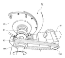
- FIG. 1 It is an enlarged perspective view of the main part which shows the rotor mounting state in the crusher in the glass crushing apparatus which concerns on this embodiment. It is a perspective view which shows the relationship between a drum part and an inner lid. It is a perspective view which shows the opening and closing procedure of a door body after attaching the inner lid of FIG. It is a perspective view which shows the bearing state of the drive rotating shaft in a crusher. It is a perspective view which shows the interlocking structure of the drive rotation shaft of a crusher and an electric motor.
- the front, back, left, right, up and down are based on FIG. 2, the front side means the left side direction of FIG. 2, and the rear side means the right side direction of the same figure. Further, the left side means the front side direction of the drawing paper leaf of FIG. 2, and the right side means the back side direction of the drawing paper leaf of the same figure. Further, the upper side and the lower side refer to the upper side direction and the lower side direction in FIG.
- the plate glass recycling method according to the present invention includes a plate glass crushing step (S0001) in which the plate glass is crushed to obtain a glass cullet, and the glass cullet obtained in the step is crushed into sandy glass powder. It has a glass cullet crushing step (S0002), and further has a sandy glass powder sieving step (S0003) for sieving the sandy glass powder obtained in the glass cullet crushing step, if necessary.
- the glass dust collecting step (S0005) (S0006) for collecting the glass dust generated in one or both of the plate glass crushing step (S0001) and the glass cullet crushing step (S0002). Has.
- the outer shape of the glass cullet obtained in the plate glass crushing step (S0001) is about 15 mm or less, and the particle size of the sandy glass powder obtained in the glass cullet crushing step is within the range of 0.3 to 5 mm. be.
- the flat glass crushing step (S0001) is performed by a glass crusher 1 provided with a pair of crushing rolls 2A and 2B for crushing the flat glass.
- the crushing rotor 52 includes a crushing rotor 56 for colliding and crushing the glass cullet in the drum portion 53, and the crushing rotor 60 via a transport pipe 60 extending from the glass crusher 52. It is executed by the preduster 54 provided with the reflector 61 that collides and crushes the sandy glass powder scattered and conveyed by the wind pressure of 56.
- the flat glass crusher 1 that executes the flat glass crushing step (S0001) for crushing the flat glass to obtain a glass cullet, and the glass cullet obtained in the step are sanded glass powder.
- a flat glass recycling system including a glass crusher 51 that performs a glass cullet crushing step (S0002) to crush the glass.
- the plate glass crusher 1 includes a pair of upper and lower plate glass crushing rolls composed of an upper roll 2A and a lower roll 2B facing each other, and pressers provided on the front side and the rear side of the upper roll 2A, respectively. It has a crusher main body 10 having a roll 6 and roller conveyors 11A and 11B provided on the front side and the rear side of the crusher main body 10, respectively, and the upper roll 2A and the lower roll 2B are orthogonal to the axial direction thereof.
- the ridges 3A and 3B having a rectangular cross section are provided around at predetermined intervals in the direction, and the ridges 3A and 3B of the upper roll 2A and the lower roll 2B are arranged alternately.
- the glass crusher 51 extends obliquely upward from the crusher 52 having a drum portion 53 incorporating a crushing rotor 56 for crushing a glass cullet that has been crushed in advance, and the crusher 52.
- the preduster 54 has a substantially linear transport pipe 60 for guiding crushed sandy glass powder in the drum portion 53 and a container-shaped preduster 54 into which the upper end of the transport pipe 60 is inserted.
- a reflector 61 that faces the upper end of the transport pipe 60 and guides the sandy glass powder discharged from the upper end of the transport pipe 60 into the preduster 54 is provided.
- glass dust collectors 21 and 92 for collecting glass dust are attached to both the plate glass crusher 1 and the preduster 54.
- the flat glass SG mounted on the rear roller conveyor 16B in the flat glass crusher 1 has an upper roll 2A and a lower roll.
- the glass cullet GC crushed by 2B and crushed is carried from the roller conveyor 16A on the front side to the glass crusher 51 by the first belt conveyor BT1, and the glass cullet GC is crushed in the glass crusher 51 to be sandy glass.
- the sandy glass powder becomes powder, and the sandy glass powder enters the preduster 54 via the transport pipe 60 and collides with the reflector 61 in the predaster 54, so that the sandy glass powder is further crushed. NS. After that, the sandy glass is carried into the sieving machine 75 by the hopper 55.
- the sandy glass powder having a predetermined particle size (for example, 5 mm) or less in the sieving machine 75 is stored in a recovery container (not shown) as a final resource.
- the sandy glass powder larger than a predetermined particle size (for example, 5 mm) in the sieving machine 75 is placed on the second belt conveyor BT2 as a return conveyor and put into the glass crusher 52 again to further crush. Is done.
- the plate glass crusher 1 As shown in FIGS. 3 to 7, the plate glass crusher 1 according to the present embodiment has an upper roll 2A and a lower side facing each other in the left-right direction in the central portion.
- a crusher main body 10 having a pair of upper and lower flat glass crushing rolls including rolls 2B is provided, and roller conveyors 11A and 11B are installed on the front side and the rear side thereof, respectively.
- the crusher main body 10 includes a pair of upper and lower plate glass crushing rolls (made of steel) composed of an upper roll 2A and a lower roll 2B facing each other in the left-right direction, and the rolls 2A and 2B, respectively.
- the ridges 3A and 3B having a rectangular cross section and the concave grooves 4A having a predetermined depth formed between the ridges 3A and 3B having a predetermined interval P (pitch) in a direction orthogonal to the axial direction of the ridges 3A and 3B.
- the 4Bs are provided around each other, and the ridges 3A and 3B and the concave grooves 4A and 4B in the upper roll 2A and the lower roll 2B are arranged alternately.
- the ridges 3A and 3B have a trapezoidal cross section whose width narrows toward the tip side, and the distance B between the upper roll 2A and the lower roll 2B is about -2 to 28 mm.
- the pitch P of the ridges 3A and 3B in each roll 2A and 2B is set within the range of about 12 to 16 mm, and the depth D of the concave grooves 4A and 4B between the ridges 3A and 3B is about. It is set within the range of 6 to 8 mm. Further, the inclination angles ⁇ of the ridges 3A and 3B are changed in the range of 12 to 20 °.
- the distance B between the upper roll 2A and the lower roll 2B is set to 6 mm or 7 mm
- the pitch P of the ridges 3A and 3B is set to 14 mm
- the depth D of the concave grooves 4A and 4B is set to 7 mm.
- presser rolls 6 for pressing the plate glass SG are rotatably supported on the front side and the rear side of the upper roll 2A in the crusher main body 10, respectively.
- the crusher main body 10 is provided with a suction duct 7 for sucking and collecting the glass powder generated when the flat glass SG is crushed, and the glass powder sucked from the suction duct 7 passes through the relay duct 22. Then, it is collected by the collector (dust collector) 21.
- a first chute 18A for receiving the cullet of the crushed solar panel glass and a second chute 18B following the first chute 18A are provided, and the lower end of the second chute 18B is on the belt conveyor 19.
- the crushed glass cullet is conveyed to the next process by the belt conveyor 19.
- a container carriage 20 for receiving the cullet of crushed solar panel glass is installed at the lower part of the roller conveyor 11B on the rear side, and the glass cullet that has fallen into the container carriage 20 is a worker (not shown). Is carried into the belt conveyor 19 by.
- rollers 16A and 16B of the roller conveyors 11A and 11B are rotated in the forward and reverse directions by the motor M4 via the sprocket 23 provided coaxially with the sprocket 23 and the chain C meshing with the sprocket 23. Has been done.
- guide bars 17A and 17B for guiding the flat glass SG are provided at intervals in the left-right direction between the front and rear roller conveyors 11A and 11B of the front and rear pressing rollers 6.
- the upper roll 2A and the lower roll 2B are rotatably supported by a pair of left and right bearings 23A and 23B in the crusher main body 10, and are supported by individual motors M1 and M2. It is designed to rotate independently. More specifically, the upper roll 2A and the lower roll 2B are rotatably supported by a pair of left and right bearings 23A and 23B in the crusher main body 10, respectively, and the ends of the upper roll 2A and the lower roll 2B, respectively.
- a chain CH is laid between the sprockets 22A and 22B attached to the rotating shafts of the motor motors M1 and M2, respectively, and the upper rolls 2A and the lower rolls 2B are rotated by the motors M1 and M2. ing.
- the shifting device 30 for shifting the rear roller conveyor 11B in the left-right direction is spaced below the rear roller conveyor 11B. It is installed in two places. More specifically, the shifting device 30 includes a ball screw 5 that is parallel and rotatable with the roller 16B of the roller conveyor 11B on the rear side, a nut-shaped female screw member 9 that moves in the left-right direction with respect to the ball screw 5, and the same. A table TB having a female screw member 9 integrally is provided. The ball screw 5 is rotatably supported on the guide rail GR by the motor M3 via the coupling 14 and the bearing 15.
- the ball screw 5 is fitted with the nut-shaped female screw member 9 inserted into the table TB, and the rotation of the ball screw 5 causes the table TB to pass through the female screw member 9.
- the structure is such that the rear roller conveyor 11B on the table TB can move in the left-right direction as well, and moves in the left-right direction along the guide rail GR.
- the outer peripheral portions of the left and right bearings 23B of the lower roll 2B are the eccentric ring 25.
- the structure is supported by being surrounded by, and the height positions of the lower roll 2B and the bearing 23B are changed by rotating the eccentric ring 25.
- a gear 27 is formed on the outer peripheral side portion of the circular base 26 provided with the eccentric ring 25, and the outer peripheral gear 27 meshes with the pinion 28, and the pinion 28 meshes with the rack 29 as a stopper.
- 23BOC indicates the outer circumference of the bearing 23B of the lower roll 2B. Further, 35 indicates the axis of the lower roll 2B, 2BOC indicates the outer circumference of the lower roll 2B, and 2AOC indicates the outer circumference of the upper roll 2A.
- the outer peripheral 2BOC of the lower roll 2B is closest to the outer peripheral 2AOC of the upper roll 2A (about -2 mm), and the figure accompanying the rotation of the eccentric ring 25.
- the outer peripheral 2BOC of the lower roll 2B is located slightly away from the outer peripheral 2AOC of the upper roll 2A (interval of about 8 mm), and FIG. 12 (c) shows that the eccentric ring 25 is further rotated.
- the outer peripheral 2BOC of the lower roll 2B is located at a position (interval of about 18 mm) significantly separated from the outer peripheral 2AOC of the upper roll 2A.
- the outer gear 27 of the circular base 26 provided with the eccentric ring 25 and the pinion 28 are meshed with each other, and the pinion 28 is meshed with the rack 29 functioning as a stopper. Therefore, the rack 29, which is a stopper, prevents the pinion 28 from rotating, and the outer gear 27 of the circular base 26 that meshes with the pinion 28 does not rotate accordingly, and as a result, it is integrated with the circular base 26.
- the eccentric ring 25 also does not rotate, and the height position of the lower roll 2B is kept constant accordingly, and in this state, the lower roll 2B is rotated by the motor M2 via the bearing 23B. ..
- 31 is a display board integrally fixed to the inner peripheral portion of the circular base 26, and a scale 32 indicating the height position of the lower roll 2B is attached to the surface, and 33 is the scale 32. It is an indicator member.
- the sprocket 22A and the chain CH of the upper roll 2A are located above the circular base 26.
- FIGS. 3 to 7 the procedure for using the flat glass crusher according to the present embodiment will be described.
- an operator shown
- the solar panel glass SG advances on the rear roller conveyor 11B and is sandwiched between the upper roll 2A and the lower roll 2B in the crusher main body 10. While being crushed, it comes out on the front roller conveyor 11A.
- the front and rear roller conveyors 11A and 11B and the upper roll 2A and the lower roll 2B are rotated in the reverse direction to rotate the solar panel.
- the glass SG is sandwiched between the upper roll 2A and the lower roll 2B again and crushed again.
- the solar panel glass SG is more closely crushed at the pressure-welded portion of the upper and lower rolls 2A and 2B.
- the shift device 30 described above is operated to move the rear roller conveyor 11B to the left and right.
- the upper and lower rolls having a trapezoidal cross-sectional trapezoidal protrusion 3A / 3B having a spacing (pitch) P of 7 mm and a recessed groove 4A / 4B between the protrusions 3A / 3B having a depth D of 14 mm according to the above-described embodiment.
- the interval (pitch) P is 10 mm
- the depth D of the concave grooves 34A and 34B between the ridges 33A and 33B is 2.5 mm.
- the upper and lower rolls 2A and 2B of the embodiment had a substantially uniform particle size and an appropriate fineness.
- a glass cullet was obtained, and as shown in FIG. 15, the back sheet of the solar panel glass was not damaged, and as shown in FIG. 16, the crushed glass was not clogged in the recessed grooves 4A and 4B at all. It did not occur.
- the upper and lower rolls 32A and 32B of the comparative form as shown in FIG. 17, the back sheet of the solar panel glass was damaged and cracks were generated, which became crushed glass cullet as contamination (impurities). It was mixed.
- the crushed glass was clogged in the concave grooves 34A and 34B, and the protrusions 33A and 33B were also significantly worn.
- the glass crusher 51 includes a crusher 52 having a drum portion 53 having a crushing rotor 56 for crushing a pre-crushed glass cullet, and a crusher.
- a substantially linear transport pipe 60 extending diagonally upward from 52 and guiding crushed glass in the drum portion 53, a container-shaped preduster 54 into which the upper end of the transport pipe 60 is inserted, and a preduster 54. It has a hopper 55 integrally provided at the lower part.
- 70 indicates a slot for the crushed glass cullet to be crushed.
- a plurality of arcuate wear-resistant steel plates are fixed as liners 57 on the inner peripheral surface of the drum portion 53 with bolts 58 and nuts 59.
- the inclination angle ⁇ of the transport pipe 60 with respect to the crusher 52 is about 60 °.
- the preduster 54 has a reflecting plate 61 that faces the upper end 60a of the transport pipe 60 and is inclined at a predetermined angle with respect to the axis of the transport pipe 60, and is a sandy glass discharged from the transport pipe 60.
- the powder collides with the reflecting plate 61 and is thrown into the preduster 54, and the sandy glass powder GS after colliding with the reflecting plate 61 is received by the hanging receiving plate 91 in the predaster 54 and falls smoothly, and the powder is smoothly dropped. It is thrown into the hopper 55. Further, the powdery glass powder GP filled in the predaster 54 flows into the chamber 95 connected to the upper part of the predaster 54, and then enters the collector 92 via the duct 94 and the butterfly damper 93.
- the collector 92 is provided with a dust collecting function including a bug filter and the like, and the powdery glass powder collected by the collector 92 is sand-like accumulated in the hopper 55. Like glass powder, it can be recycled as a material.
- the sandy glass powder GS falls into the hopper 55 by its own weight, and only the powdery glass GP having a very light specific gravity is sucked into the collector 92.
- 62 shows a window for visually observing the inside of the preduster 54.
- the crushing rotor 56 includes a circular substrate 66 having a bearing 64 of a rotary drive shaft 63 in the center, and a plurality of crushing plates 67 radially provided on one surface of the circular substrate 66.
- a ring-shaped plate 68 attached to the end of the entire crushed plate 67 is provided so as to orbit the end of each crushed plate 67.
- the rotary drive shaft 63 projects from the central portion of the drum portion 53, and the bearing 64 of the crushing rotor 56 is fitted to the rotary drive shaft 63 and fixed by the stop nut 71.
- the crushing rotor 56 is rotatably supported by such a structure.
- An inner lid 72 is attached to the drum portion 53 in which the crushing rotor 56 is built, and a door body 73 is attached to the outside of the inner lid 72 via a hinge 90, and the drum portion 53 is opened and closed by the door body 73. It is made free.
- the inner lid 72 has the same shape as the ring-shaped plate 68 of the crushing rotor 56.
- the rotary drive shaft 63 of the crushing rotor 56 is rotated by the electric motor M via a pair of pulleys 74A and 74B, a belt B, and a bearing 81. It has a structure, and its rotation is such that the sandy glass powder crushed by the crushing rotor 56 is guided into the transport pipe 60.
- a sieving machine 75 is installed below the hopper 55.
- the glass cullet GC collides with the crushing plate 67 of the rotating crushing rotor 56 and is crushed, and after colliding with the crushing plate 67.
- the glass cullet GC is further crushed by colliding with a wear-resistant liner 57 attached to the inner peripheral surface of the drum portion 53 so as to surround the crushing rotor 56, and the drum portion 53 is further crushed in such a crushed state.
- the glass cullet GC which had sharp corners when it was thrown in from the slot 70 due to collision between the glass cullet GCs flying inside, was crushed and the sharp corners disappeared due to wear, and finally. It becomes a fine sandy glass powder GS with sharp edges.
- a swirling air vortex that winds up the glass cullet GC is generated in the drum portion 53 with the rotation of the crushing rotor 56, and the outer shape is crushed to about several millimeters by the above-mentioned crushing.
- the glass powder GS rises in the transport pipe 60 and is guided to the preduster 54 by the hoisting air vortex.
- the transport pipe 60 has a substantially direct shape, the sandy glass powder GC smoothly enters the preduster 54 without stagnation during transport and without any resistance.
- the sandy glass powder GS that has entered collides with the inclined reflective plate 61 arranged so as to face the upper end of the transport pipe 60, and further, the reflective plate 61 is subjected to the collision.
- the sandy glass powder GS after the collision is received by the hanging receiving plate 91 in the preduster 54 and falls downward, and finally the sandy glass powder GS falls on the hopper 55 below the predaster 54. Then, the sandy glass powder GS flows from the hopper 55 into the sieving machine 75.
- the glass cullet GC that has not been sufficiently crushed in the drum portion 53 does not rise due to the hoisting swirling air vortex in the drum portion 53 accompanying the rotation of the crushing rotor 56, but falls by its own weight and again the crushing rotor. It collides with the crushed plate 67 of 56, collides with the liner 57 due to the reaction thereof, and is further pulverized by the collision between the glass cullet GCs. Then, when the fine sandy glass powder GS whose outer shape is crushed to about several millimeters is obtained by repeating such crushing, the sandy glass powder GS becomes the drum portion 53 accompanying the rotation of the crushing rotor 56. It rises by the winding swirling air vortex inside and is guided into the transport pipe 60.
Abstract
[Problem] To make a sheet glass to have proper grain diameters in a dried state, and to make the grain diameters uniform by a simple method. [Solution] A sheet glass crushing step (S0001) of crushing a sheet glass to produce glass cullet, and a glass cullet pulverization step (S0002) of pulverizing the glass cullet produced in the aforementioned step into a sand-like glass powder are provided, and optionally a sand-like glass powder sieving step (S0003) of sieving the sand-like glass powder produced in the glass cullet pulverization step is further provided. Furthermore, optionally, a glass powder pulverization step (S0004) of returning a portion of the sand-like glass powder which has a larger grain size than a predetermined grain size in the sand-like glass powder sieving step (S0003) to the glass cullet pulverization step (S0002) to pulverize the portion again is provided, and a glass powder dust trapping step (S0005) (S0006) of trapping glass powder dusts formed in one or both of the sheet glass crushing step (S0001) and the glass cullet pulverization step (S0002) is also provided.
Description
本発明は、太陽光パネルガラス、自動車ガラス、窓ガラスおよび遊戯機ガラス等として使用された板ガラスを資源化するためのリサイクルシステムおよびリサイクル方法に関する。
The present invention relates to a recycling system and a recycling method for recycling flat glass used as solar panel glass, automobile glass, window glass, amusement machine glass, and the like.
板ガラスは、前述した通り、太陽光パネルガラス、自動車ガラス、窓ガラスおよび遊戯機ガラス等として種々の分野で使用されているが、その資源化率は低く、廃棄される板ガラスは、通常、シュレッダーダストとして地中に埋められることが多い。
As described above, flat glass is used in various fields as solar panel glass, automobile glass, window glass, amusement machine glass, etc., but its resource recovery rate is low, and the discarded flat glass is usually shredder dust. It is often buried in the ground.
また、廃棄処分となる板ガラスは、割った場合に鋭利なガラスカレットとなり、またその形状も不定形且つ大小様々であるため、取扱い難く、リサイクルに適していないのが実情である。
In addition, the flat glass to be disposed of becomes a sharp glass cullet when broken, and the shape is irregular and various in size, so it is difficult to handle and it is not suitable for recycling.
そして、従来のガラスリサイクル方法としては、シート或いはフィルム付き廃棄ガラスを再利用するためのガラスリサイクル方法であって、 廃棄ガラスを破砕し、破砕されたガラス片をサイズが異なる少なくとも2つのガラス片にふるい選別し、ふるい選別されたガラス片の一部を再利用ガラスとして回収し、ふるい選別されたガラス片の他の一部とシートあるいはフィルム片とを風力選別し、風力選別されたガラス片を再利用ガラスとして回収するようにしたリサイクル方法が知られている。
The conventional glass recycling method is a glass recycling method for reusing waste glass with a sheet or a film, in which the waste glass is crushed and the crushed glass pieces are divided into at least two glass pieces having different sizes. Sifted and collected a part of the screened glass piece as recycled glass, wind-sorted the other part of the screened glass piece and the sheet or film piece, and wind-sorted the glass piece. A recycling method is known in which the glass is collected as recycled glass.
また、建設複合廃材から骨材を分離回収する方法として、比重の差が殆どない骨材とガラス成分に対して、骨材とガラス成分の破砕強度の差を利用して摩鉱によりガラス成分を骨材より微粉化させて分級し骨材を回収する方法が知られている。
In addition, as a method of separating and recovering aggregates from construction composite waste materials, glass components are separated by ore by utilizing the difference in crushing strength between aggregates and glass components with respect to aggregates and glass components with almost no difference in specific gravity. A method is known in which the aggregate is pulverized from the aggregate, classified, and the aggregate is recovered.
前述した従来技術のうち、シート或いはフィルム付き廃棄ガラスを再利用するためのガラスリサイクル方法の場合、選別対象となるガラスの粒径が一定化し難く、ふるい選別の作業に手間を要するという不都合があった。
Among the above-mentioned conventional techniques, in the case of the glass recycling method for reusing waste glass with a sheet or film, there is an inconvenience that the particle size of the glass to be sorted is difficult to be constant and the sieving sorting work requires time and effort. rice field.
また、建設複合廃材における骨材とガラス成分の分離を行うリサイクル方法では、湿式比重選別機を用いる必要があるため、その廃液処理その他に多大な手間と環境負荷がかかるという問題があった。
In addition, since it is necessary to use a wet specific gravity sorter in the recycling method for separating the aggregate and the glass component in the construction composite waste material, there is a problem that a great deal of labor and environmental load are required for the waste liquid treatment and others.
本発明の目的は、乾式で板ガラスを適度の粒径にすることができ、しかも該粒径を容易に一定化することが可能な板ガラスのリサイクル方法およびリサイクルシステムを提供することにある。
An object of the present invention is to provide a method and a recycling system for flat glass, which can be dried to have an appropriate particle size and can easily make the particle size constant.
請求項1記載の本発明は、板ガラスを破砕してガラスカレットを得る板ガラス破砕工程と、該工程で得られたガラスカレットを砂状ガラス粉に粉砕するガラスカレット粉砕工程を有する、板ガラスのリサイクル方法である。
The present invention according to claim 1 comprises a plate glass crushing step of crushing a plate glass to obtain a glass cullet, and a glass cullet crushing step of crushing the glass cullet obtained in the step into sandy glass powder. Is.
請求項2記載の本発明は、前記請求項1記載の板ガラスのリサイクル方法について、更に、ガラスカレット粉砕工程で得られた砂状ガラス粉を篩分けする砂状ガラス粉篩分け工程を有することを特徴とする。
The present invention according to claim 2 further includes a sandy glass powder sieving step for sieving the sandy glass powder obtained in the glass cullet crushing step with respect to the plate glass recycling method according to claim 1. It is a feature.
請求項3記載の本発明は、前記請求項1または請求項2記載の板ガラスのリサイクル方法について、更に、ガラス粉篩分け工程で所定粒度より大きい砂状ガラス粉をガラスカレット粉砕工程に戻して再粉砕するガラス粉粉砕工程を有することを特徴とする。
The present invention according to claim 3 relates to the method for recycling flat glass according to claim 1 or 2, further, in a glass powder sieving step, sandy glass powder larger than a predetermined particle size is returned to a glass cullet crushing step and re-processed. It is characterized by having a glass powder crushing step for crushing.
請求項4記載の本発明は、前記請求項1~請求項3のうちのいずれか一項記載の板ガラスのリサイクル方法について、板ガラス破砕工程におけるガラスカレットの外形が、15mm以下であることを特徴とする。
The present invention according to claim 4 is characterized in that the outer shape of the glass cullet in the plate glass crushing step is 15 mm or less in the method for recycling the plate glass according to any one of claims 1 to 3. do.
請求項5記載の本発明は、前記請求項1~請求項4のうちのいずれか一項記載の板ガラスのリサイクル方法について、ガラスカレット粉砕工程で得られる砂状ガラス粉の粒度が、0.3~5mmの範囲内であることを特徴とする。
According to the fifth aspect of the present invention, the particle size of the sandy glass powder obtained in the glass cullet crushing step is 0.3 in the method for recycling the flat glass according to any one of the first to fourth aspects. It is characterized in that it is within the range of about 5 mm.
請求項6記載の本発明は、前記請求項1~請求項5のうちのいずれか一項記載の板ガラスのリサイクル方法について、更に、板ガラス破砕工程とガラスカレット粉砕工程の一方または両方の工程で、発生するガラス粉塵を捕集するガラス粉塵捕集工程を有することを特徴とする。
The present invention according to claim 6 relates to the method for recycling flat glass according to any one of claims 1 to 5, further, in one or both steps of a flat glass crushing step and a glass cullet crushing step. It is characterized by having a glass dust collecting step for collecting the generated glass dust.
請求項7記載の本発明は、請求項1~請求項6のうちのいずれか一項記載の板ガラスのリサイクル方法について、板ガラス破砕工程が、板ガラスを圧潰する一対の破砕ロールを備えたガラス破砕機によって行われることを特徴とする。
The present invention according to claim 7 is a glass crusher provided with a pair of crushing rolls in which the plate glass crushing step crushes the plate glass according to the method for recycling the plate glass according to any one of claims 1 to 6. It is characterized by being done by.
請求項8記載の本発明は、前記請求項1~請求項7のうちのいずれか一項記載の板ガラスのリサイクル方法について、ガラスカレット粉砕工程が、ドラム部内でガラスカレットを衝突粉砕する粉砕用ロータを備えたガラス粉砕機と、ガラス粉砕機から伸びる搬送用パイプを介して前記粉砕用ロータの風圧で飛散搬送される砂状ガラス粉を衝突粉砕する反射板を備えたプレダスタとによって行われることを特徴とする。
The present invention according to claim 8 relates to the method for recycling flat glass according to any one of claims 1 to 7, wherein the glass cullet pulverization step collides and pulverizes the glass cullet in the drum portion. This is done by a glass crusher equipped with a glass crusher and a preduster equipped with a reflector for colliding and crushing sandy glass powder scattered and conveyed by the wind pressure of the crushing rotor via a transport pipe extending from the glass crusher. It is a feature.
請求項9記載の本発明は、前記請求項1~請求項8のうちのいずれか一項記載の板ガラスのリサイクル方法について、板ガラスが太陽光パネルガラスであって、太陽光パネルにおける板ガラスの破砕工程後に太陽光パネルのモジュールを排除して、ガラスカレットのみを粉砕することを特徴とする。
The present invention according to claim 9 relates to the method for recycling a flat glass according to any one of claims 1 to 8, wherein the flat glass is a solar panel glass and a step of crushing the flat glass in the solar panel. It is characterized by later eliminating the solar panel module and crushing only the glass cullet.
請求項10記載の本発明は、前記請求項1~請求項9のうちのいずれか一項記載の板ガラスリサイクル方法に使用する板ガラスリサイクルシステムであって、板ガラスを破砕してガラスカレットを得る板ガラス破砕工程を実行する板ガラス破砕機と、該工程で得られたガラスカレットを砂状ガラス粉に粉砕するガラスカレット粉砕工程を実行するガラス粉砕装置を備え、板ガラス破砕機は、互いに対向する上側ロールと下側ロールとからなる上下一対の板ガラス破砕ロール並びに前記上側ロールの前側および後側にそれぞれ設けられた押えロールを有する破砕機本体と、破砕機本体の前側および後側にそれぞれ設けられたローラコンベアを有し、前記上側ロールおよび下側ロールにはその軸線方向と直交する方向に所定間隔をあけて横断面方形の凸条が周設され、且つ上側ロールと下側ロールの凸条は互い違いに配設されているものである。
The present invention according to claim 10 is a flat glass recycling system used in the flat glass recycling method according to any one of claims 1 to 9, wherein the flat glass is crushed to obtain a glass cullet. A plate glass crusher that executes the process and a glass cullet crusher that executes a glass cullet crushing step of crushing the glass cullet obtained in the process into sandy glass powder are provided. A crusher main body having a pair of upper and lower flat glass crushing rolls composed of side rolls, holding rolls provided on the front side and the rear side of the upper roll, respectively, and roller conveyors provided on the front side and the rear side of the crusher main body, respectively. The upper roll and the lower roll are provided with square ridges having a cross section at predetermined intervals in a direction orthogonal to the axial direction thereof, and the ridges of the upper roll and the lower roll are arranged alternately. It is installed.
請求項11記載の本発明は、前記請求項10記載の板ガラスリサイクルシステムについて、板ガラス破砕機の上下ロールの凸条が先端側に向かって幅が狭い横断面台形となされていることを特徴とする。
The present invention according to claim 11 is characterized in that, in the plate glass recycling system according to claim 10, the ridges of the upper and lower rolls of the plate glass crusher have a trapezoidal cross section narrowing toward the tip side. ..
請求項12記載の本発明は、前記請求項10または請求項11記載の板ガラスリサイクルシステムについて、ガラス粉砕装置は、予め破砕されたガラスカレットを粉砕する粉砕用ロータが内蔵されたドラム部を有する粉砕機と、粉砕機から斜め上方に伸び、前記ドラム部内で粉砕された砂状ガラス粉を誘導する略直線状の搬送用パイプと、搬送用パイプの上端が挿入された容器状のプレダスタとを有し、プレダスタが、前記搬送用パイプの上端と対向し、且つ搬送用パイプの上端から吐出する砂状ガラス粉をプレダスタ内へ誘導する反射板を備えていることを特徴とする。
According to the twelfth aspect of the present invention, in the flat glass recycling system according to the tenth or eleventh aspect, the glass crushing device includes a drum portion having a crushing rotor for crushing a pre-crushed glass cullet. It has a machine, a substantially linear transport pipe that extends diagonally upward from the crusher and guides crushed sandy glass powder in the drum portion, and a container-shaped preduster into which the upper end of the transport pipe is inserted. The preduster is provided with a reflector that faces the upper end of the transport pipe and guides the sandy glass powder discharged from the upper end of the transport pipe into the preduster.
請求項13記載の本発明は、請求項10~請求項12のうちのいずれか一項記載の板ガラスリサイクルシステムについて、更に、板ガラス破砕機とプレダスタの一方または両方にガラス粉塵を捕集するガラス粉塵捕集機が付設されていることを特徴とする。
The present invention according to claim 13 is the glass dust recycling system according to any one of claims 10 to 12, and further, glass dust that collects glass dust in one or both of a flat glass crusher and a preduster. It is characterized by being equipped with a collector.
本発明に係る板ガラスのリサイクル方法によれば、太陽光パネルガラス、自動車ガラス、窓ガラスおよび遊戯機ガラス等として使用された板ガラスを最終的に一定粒度の細かな砂状のガラス粉とすることができるため、従来に比べて、板ガラスの資源化が高度に実現される。
According to the method for recycling flat glass according to the present invention, flat glass used as solar panel glass, automobile glass, window glass, amusement machine glass, etc. can be finally made into fine sandy glass powder having a certain particle size. Therefore, the recycling of flat glass is highly realized as compared with the conventional case.
また、本発明に係る板ガラスのリサイクル方法は、乾式で行えるため、従来の湿式比重選別機のような廃液処理の問題もなく、またリサイクル作業における環境負荷の問題も解消される。
Further, since the flat glass recycling method according to the present invention can be performed by a dry method, there is no problem of waste liquid treatment unlike the conventional wet specific gravity sorter, and the problem of environmental load in the recycling work is also solved.
更に、本発明のリサイクル方法によれば、前述した通り、最終的に得られる砂状ガラスを、道路構築材として利用したり、装飾用材として利用することができ、幅広い分野での利用が期待できる。
Further, according to the recycling method of the present invention, as described above, the finally obtained sandy glass can be used as a road construction material or a decorative material, and can be expected to be used in a wide range of fields. ..
特に、板ガラスを破砕してガラスカレットを得る板ガラス破砕工程を実行する板ガラス破砕機と、該工程で得られたガラスカレットを砂状ガラス粉に粉砕するガラスカレット粉砕工程を実行するガラス粉砕装置を備え、板ガラス破砕機が、互いに対向する上側ロールと下側ロールとからなる上下一対の板ガラス破砕ロール並びに前記上側ロールの前側および後側にそれぞれ設けられた押えロールを有する破砕機本体と、破砕機本体の前側および後側にそれぞれ設けられたローラコンベアを有し、前記上側ロールおよび下側ロールにはその軸線方向と直交する方向に所定間隔をあけて横断面方形の凸条が周設され、且つ上側ロールと下側ロールの凸条は互い違いに配設されている請求項10記載の板ガラスリサイクルシステムによれば、前述した種々の効果が容易且つ確実に得られる。
In particular, it is provided with a plate glass crusher that executes a plate glass crushing step of crushing plate glass to obtain a glass cullet, and a glass crushing device that executes a glass cullet crushing step of crushing the glass cullet obtained in the step into sandy glass powder. , A crusher main body having a pair of upper and lower plate glass crushing rolls composed of an upper roll and a lower roll facing each other, and holding rolls provided on the front side and the rear side of the upper roll, respectively, and a crusher main body. The upper roll and the lower roll are provided with roller conveyors on the front side and the rear side, respectively, and ridges having a rectangular cross section are provided around the upper roll and the lower roll at predetermined intervals in a direction orthogonal to the axial direction thereof. According to the flat glass recycling system according to claim 10, in which the ridges of the upper roll and the lower roll are arranged alternately, the various effects described above can be easily and surely obtained.
また、ガラス粉砕装置が、予め破砕されたガラスカレットを粉砕する粉砕用ロータが内蔵されたドラム部を有する粉砕機と、粉砕機から斜め上方に伸び、前記ドラム部内で粉砕された砂状ガラス粉を誘導する略直線状の搬送用パイプと、搬送用パイプの上端が挿入された容器状のプレダスタとを有し、プレダスタが、前記搬送用パイプの上端と対向し、且つ搬送用パイプの上端から吐出する砂状ガラス粉をプレダスタ内へ誘導する反射板を備えていることを特徴とする請求項12記載の板ガラスリサイクルシステムによれば、前述した種々の効果が更に重畳的に得られる。
Further, the glass crusher includes a crusher having a drum portion having a crushing rotor for crushing a glass cullet that has been crushed in advance, and sandy glass powder that extends diagonally upward from the crusher and is crushed in the drum portion. It has a substantially linear transport pipe for guiding the transport pipe and a container-shaped preduster into which the upper end of the transport pipe is inserted, and the preduster faces the upper end of the transport pipe and is from the upper end of the transport pipe. According to the plate glass recycling system according to claim 12, which includes a reflecting plate that guides the sandy glass powder to be discharged into the preduster, the various effects described above can be obtained in a superposed manner.
次に、本発明の実施形態を図面にしたがって説明するが、本発明はかかる実施形態に限定されるものではない。
Next, an embodiment of the present invention will be described with reference to the drawings, but the present invention is not limited to such an embodiment.
なお、本実施形態において、前後左右上下は、図2を基準とし、前側とは図2の左側方向を指し、後側とは同図右側方向を意味する。また、左側とは図2の図面紙葉の表側方向を指し、右側とは同図、図面紙葉の裏側方向を意味するものとする。更に、上側下側とは、図2における上側方向、下側方向を指すものとする。
In the present embodiment, the front, back, left, right, up and down are based on FIG. 2, the front side means the left side direction of FIG. 2, and the rear side means the right side direction of the same figure. Further, the left side means the front side direction of the drawing paper leaf of FIG. 2, and the right side means the back side direction of the drawing paper leaf of the same figure. Further, the upper side and the lower side refer to the upper side direction and the lower side direction in FIG.
図1に示すように、本発明に係る板ガラスのリサイクル方法は、板ガラスを破砕してガラスカレットを得る板ガラス破砕工程(S0001)と、該工程で得られたガラスカレットを砂状ガラス粉に粉砕するガラスカレット粉砕工程(S0002)とを有し、更に必要に応じて、前記ガラスカレット粉砕工程で得られた砂状ガラス粉を篩分けする砂状ガラス粉篩分け工程(S0003)を有する。
As shown in FIG. 1, the plate glass recycling method according to the present invention includes a plate glass crushing step (S0001) in which the plate glass is crushed to obtain a glass cullet, and the glass cullet obtained in the step is crushed into sandy glass powder. It has a glass cullet crushing step (S0002), and further has a sandy glass powder sieving step (S0003) for sieving the sandy glass powder obtained in the glass cullet crushing step, if necessary.
また、本実施形態の板ガラスリサイクル方法では、更に前記砂状ガラス粉篩分け工程(S0003)で所定粒度より大きい砂状ガラス粉をガラスカレット粉砕工程(S0002)に戻して再粉砕するガラス粉粉砕工程(S0004)を有する。
Further, in the plate glass recycling method of the present embodiment, a glass powder crushing step of returning sandy glass powder larger than a predetermined particle size to a glass cullet crushing step (S0002) in the sandy glass powder sieving step (S0003) and re-grinding it. (S0004).
この他、本実施形態では、前記板ガラス破砕工程(S0001)とガラスカレット粉砕工程(S0002)の一方または両方の工程で、発生するガラス粉塵を捕集するガラス粉塵捕集工程(S0005)(S0006)を有する。
In addition, in the present embodiment, the glass dust collecting step (S0005) (S0006) for collecting the glass dust generated in one or both of the plate glass crushing step (S0001) and the glass cullet crushing step (S0002). Has.
本実施形態では、前記板ガラス破砕工程(S0001)で得られるガラスカレットの外形は約15mm以下であり、ガラスカレット粉砕工程で得られる砂状ガラス粉の粒度は、0.3~5mmの範囲内である。
In the present embodiment, the outer shape of the glass cullet obtained in the plate glass crushing step (S0001) is about 15 mm or less, and the particle size of the sandy glass powder obtained in the glass cullet crushing step is within the range of 0.3 to 5 mm. be.
図2に示すように、本実施形態に係る板ガラスのリサイクル方法は、前記板ガラス破砕工程(S0001)が、板ガラスを圧潰する一対の破砕ロール2A・2Bを備えたガラス破砕機1によって行われ、前記ガラスカレット粉砕工程(S0002)が、ドラム部53内でガラスカレットを衝突粉砕する粉砕用ロータ56を備えたガラス粉砕機52と、ガラス粉砕機52から伸びる搬送用パイプ60を介して前記粉砕用ロータ56の風圧で飛散搬送される砂状ガラス粉を衝突粉砕する反射板61を備えたプレダスタ54によって実行されるものである。
As shown in FIG. 2, in the method for recycling flat glass according to the present embodiment, the flat glass crushing step (S0001) is performed by a glass crusher 1 provided with a pair of crushing rolls 2A and 2B for crushing the flat glass. In the glass cullet crushing step (S0002), the crushing rotor 52 includes a crushing rotor 56 for colliding and crushing the glass cullet in the drum portion 53, and the crushing rotor 60 via a transport pipe 60 extending from the glass crusher 52. It is executed by the preduster 54 provided with the reflector 61 that collides and crushes the sandy glass powder scattered and conveyed by the wind pressure of 56.
すなわち、本実施形態に係る板ガラスのリサイクル方法は、板ガラスを破砕してガラスカレットを得る板ガラス破砕工程(S0001)を実行する板ガラス破砕機1と、該工程で得られたガラスカレットを砂状ガラス粉に粉砕するガラスカレット粉砕工程(S0002)を実行するガラス粉砕装置51を備えている板ガラスリサイクルシステムによって行われるのである。
That is, in the method for recycling the flat glass according to the present embodiment, the flat glass crusher 1 that executes the flat glass crushing step (S0001) for crushing the flat glass to obtain a glass cullet, and the glass cullet obtained in the step are sanded glass powder. This is done by a flat glass recycling system including a glass crusher 51 that performs a glass cullet crushing step (S0002) to crush the glass.
そして、板ガラスのリサイクルシステムにおいて、板ガラス破砕機1は、互いに対向する上側ロール2Aと下側ロール2Bとからなる上下一対の板ガラス破砕ロール並びに前記上側ロール2Aの前側および後側にそれぞれ設けられた押えロール6を有する破砕機本体10と、破砕機本体10の前側および後側にそれぞれ設けられたローラコンベア11A・11Bを有し、前記上側ロール2Aおよび下側ロール2Bにはその軸線方向と直交する方向に所定間隔をあけて横断面方形の凸条3A・3Bが周設され、且つ上側ロール2Aと下側ロール2Bの凸条3A・3Bは互い違いに配設されているものである。
Then, in the plate glass recycling system, the plate glass crusher 1 includes a pair of upper and lower plate glass crushing rolls composed of an upper roll 2A and a lower roll 2B facing each other, and pressers provided on the front side and the rear side of the upper roll 2A, respectively. It has a crusher main body 10 having a roll 6 and roller conveyors 11A and 11B provided on the front side and the rear side of the crusher main body 10, respectively, and the upper roll 2A and the lower roll 2B are orthogonal to the axial direction thereof. The ridges 3A and 3B having a rectangular cross section are provided around at predetermined intervals in the direction, and the ridges 3A and 3B of the upper roll 2A and the lower roll 2B are arranged alternately.
また、板ガラスのリサイクルシステムにおいて、前記ガラス粉砕装置51は、予め破砕されたガラスカレットを粉砕する粉砕用ロータ56が内蔵されたドラム部53を有する粉砕機52と、粉砕機52から斜め上方に伸び、前記ドラム部53内で粉砕された砂状ガラス粉を誘導する略直線状の搬送用パイプ60と、搬送用パイプ60の上端が挿入された容器状のプレダスタ54とを有し、プレダスタ54が、前記搬送用パイプ60の上端と対向し、且つ搬送用パイプ60の上端から吐出する砂状ガラス粉をプレダスタ54内へ誘導する反射板61を備えている。
Further, in the flat glass recycling system, the glass crusher 51 extends obliquely upward from the crusher 52 having a drum portion 53 incorporating a crushing rotor 56 for crushing a glass cullet that has been crushed in advance, and the crusher 52. The preduster 54 has a substantially linear transport pipe 60 for guiding crushed sandy glass powder in the drum portion 53 and a container-shaped preduster 54 into which the upper end of the transport pipe 60 is inserted. A reflector 61 that faces the upper end of the transport pipe 60 and guides the sandy glass powder discharged from the upper end of the transport pipe 60 into the preduster 54 is provided.
また、本実施形態では、前記板ガラス破砕機1とプレダスタ54の両方にガラス粉塵を捕集するガラス粉塵捕集機21・92が付設されている。
Further, in the present embodiment, glass dust collectors 21 and 92 for collecting glass dust are attached to both the plate glass crusher 1 and the preduster 54.
次に、図2に示すように、前記板ガラスリサイクルシステムによるリサイクル方法の全体構成について説明すると、板ガラス破砕機1における後側のローラコンベア16B上に載せられた板ガラスSGは上側ロール2Aと下側ロール2Bによって圧潰され、圧潰されたガラスカレットGCは前側のローラコンベア16Aから第一ベルトコンベアBT1によって、ガラス粉砕機51へ運ばれ、該ガラス粉砕機51内でガラスカレットGCは粉砕されて砂状ガラス粉となり、該砂状ガラス粉は搬送用パイプ60を介して前記プレダスタ54内に進入して該プレダスタ54内の反射板61に砂状ガラス粉が衝突することで砂状ガラス粉は更に粉砕される。その後、前記砂状ガラスはホッパ55によって篩機75に搬入される。そして、該篩機75内で所定粒度(例えば5mm)以下の砂状ガラス粉は、最終的な資源として回収用コンテナ(図示せず)に収容される。一方、前記篩機75内で所定粒度(例えば5mm)より大きいス砂状ガラス粉はリターン用コンベアとしての第二ベルトコンベアBT2に載せられて再び前記ガラス粉砕機52内へ投入され、更なる粉砕が行われる。
Next, as shown in FIG. 2, the overall configuration of the recycling method by the flat glass recycling system will be described. The flat glass SG mounted on the rear roller conveyor 16B in the flat glass crusher 1 has an upper roll 2A and a lower roll. The glass cullet GC crushed by 2B and crushed is carried from the roller conveyor 16A on the front side to the glass crusher 51 by the first belt conveyor BT1, and the glass cullet GC is crushed in the glass crusher 51 to be sandy glass. The sandy glass powder becomes powder, and the sandy glass powder enters the preduster 54 via the transport pipe 60 and collides with the reflector 61 in the predaster 54, so that the sandy glass powder is further crushed. NS. After that, the sandy glass is carried into the sieving machine 75 by the hopper 55. Then, the sandy glass powder having a predetermined particle size (for example, 5 mm) or less in the sieving machine 75 is stored in a recovery container (not shown) as a final resource. On the other hand, the sandy glass powder larger than a predetermined particle size (for example, 5 mm) in the sieving machine 75 is placed on the second belt conveyor BT2 as a return conveyor and put into the glass crusher 52 again to further crush. Is done.
次に、前述した板ガラス破砕機の詳細について説明すると、 図3~図7に示すように、本実施形態に係る板ガラス破砕機1は、中央部分に、左右方向に対向する上側ロール2Aと下側ロール2Bとからなる上下一対の板ガラス破砕ロールを備えた破砕機本体10が設けられ、その前側および後側にそれぞれローラコンベア11A・11Bが設置されている。
Next, the details of the plate glass crusher described above will be described. As shown in FIGS. 3 to 7, the plate glass crusher 1 according to the present embodiment has an upper roll 2A and a lower side facing each other in the left-right direction in the central portion. A crusher main body 10 having a pair of upper and lower flat glass crushing rolls including rolls 2B is provided, and roller conveyors 11A and 11B are installed on the front side and the rear side thereof, respectively.
より詳細には、破砕機本体10は、前述した通り、互いに左右方向に対向する上側ロール2Aと下側ロール2Bとからなる上下一対の板ガラス破砕ロール(鋼鉄製)を備え、各ロール2A・2Bには、それらの軸線方向と直交する方向に所定間隔P(ピッチ)をあけて横断面方形の凸条3A・3Bと、これら凸条3A・3B間に形成された所定深さの凹溝4A・4Bがそれぞれ周設され、且つ上側ロール2Aと下側ロール2Bにおける前記凸条3A・3B同士並びに前記凹溝4A・4B同士はそれぞれ互い違いに配設されている。
More specifically, as described above, the crusher main body 10 includes a pair of upper and lower plate glass crushing rolls (made of steel) composed of an upper roll 2A and a lower roll 2B facing each other in the left-right direction, and the rolls 2A and 2B, respectively. The ridges 3A and 3B having a rectangular cross section and the concave grooves 4A having a predetermined depth formed between the ridges 3A and 3B having a predetermined interval P (pitch) in a direction orthogonal to the axial direction of the ridges 3A and 3B. The 4Bs are provided around each other, and the ridges 3A and 3B and the concave grooves 4A and 4B in the upper roll 2A and the lower roll 2B are arranged alternately.
また、凸条3A・3Bは、本実施形態では、先端側に向かって幅が狭い横断面台形となされており、上側ロール2Aと下側ロール2Bとの間隔Bは、大体-2~28mm程度の範囲で変更され、各ロール2A・2Bにおける凸条3A・3BのピッチPは約12~16mmの範囲内に設定され、凸条3A・3B間の凹溝4A・4Bの深さDは約6~8mmの範囲内に設定される。また、凸条3A・3Bの傾斜角度αは12~20°の範囲で変更される。
Further, in the present embodiment, the ridges 3A and 3B have a trapezoidal cross section whose width narrows toward the tip side, and the distance B between the upper roll 2A and the lower roll 2B is about -2 to 28 mm. The pitch P of the ridges 3A and 3B in each roll 2A and 2B is set within the range of about 12 to 16 mm, and the depth D of the concave grooves 4A and 4B between the ridges 3A and 3B is about. It is set within the range of 6 to 8 mm. Further, the inclination angles α of the ridges 3A and 3B are changed in the range of 12 to 20 °.
本実施形態では、上側ロール2Aと下側ロール2Bの間隔Bは、6mmまたは7mmに設定され、凸条3A・3BのピッチPは14mm、凹溝4A・4Bの深さDは7mmに設定されている。
また、破砕機本体10における上側ロール2Aの前側および後側にはそれぞれ板ガラスSGを押える押えロール6が回転自在に軸支されている。 In the present embodiment, the distance B between theupper roll 2A and the lower roll 2B is set to 6 mm or 7 mm, the pitch P of the ridges 3A and 3B is set to 14 mm, and the depth D of the concave grooves 4A and 4B is set to 7 mm. ing.
Further, presser rolls 6 for pressing the plate glass SG are rotatably supported on the front side and the rear side of theupper roll 2A in the crusher main body 10, respectively.
また、破砕機本体10における上側ロール2Aの前側および後側にはそれぞれ板ガラスSGを押える押えロール6が回転自在に軸支されている。 In the present embodiment, the distance B between the
Further, presser rolls 6 for pressing the plate glass SG are rotatably supported on the front side and the rear side of the
更に、破砕機本体10には、板ガラスSGの破砕の際に発生するガラス粉を吸引捕集するための吸引ダクト7が配設され、吸引ダクト7から吸引されたガラス粉は中継ダクト22を経由して捕集機(集塵機)21に捕集される。
Further, the crusher main body 10 is provided with a suction duct 7 for sucking and collecting the glass powder generated when the flat glass SG is crushed, and the glass powder sucked from the suction duct 7 passes through the relay duct 22. Then, it is collected by the collector (dust collector) 21.
また、前記下側ロール2Bの下方には破砕された太陽光パネルガラスのカレットを受ける第一シュート18Aとこれに続く第二シュート18Bが設けられ、更に第二シュート18Bの下端はベルトコンベア19上に位置しており、かかる構造によって、破砕されたガラスカレットは前記ベルトコンベア19によって次工程へ搬送されるようになされている。更に、後側のローラコンベア11Bの下部には、破砕された太陽光パネルガラスのカレットを受けるコンテナ台車20が設置され、該コンテナ台車20内へ落下したガラスカレットは、作業員(図示せず)によって前記ベルトコンベア19へ搬入される。
Further, below the lower roll 2B, a first chute 18A for receiving the cullet of the crushed solar panel glass and a second chute 18B following the first chute 18A are provided, and the lower end of the second chute 18B is on the belt conveyor 19. With such a structure, the crushed glass cullet is conveyed to the next process by the belt conveyor 19. Further, a container carriage 20 for receiving the cullet of crushed solar panel glass is installed at the lower part of the roller conveyor 11B on the rear side, and the glass cullet that has fallen into the container carriage 20 is a worker (not shown). Is carried into the belt conveyor 19 by.
また、本実施形態において、ローラコンベア11A・11Bにおける各ローラ16A・16Bは、それらと同軸に設けられたスプロケット23と該スプロケット23と噛合するチェーンCを介してモータM4により正逆回動するようになされている。
Further, in the present embodiment, the rollers 16A and 16B of the roller conveyors 11A and 11B are rotated in the forward and reverse directions by the motor M4 via the sprocket 23 provided coaxially with the sprocket 23 and the chain C meshing with the sprocket 23. Has been done.
更に、前後の押えローラ6の前側と後側におけるローラコンベア11A・11Bとの間には、板ガラスSGを誘導する誘導バー17A・17Bが左右方向に間隔をあけて設けられている。
Further, guide bars 17A and 17B for guiding the flat glass SG are provided at intervals in the left-right direction between the front and rear roller conveyors 11A and 11B of the front and rear pressing rollers 6.
更に、図8および図9に示すように、上側ロール2Aと下側ロール2Bは、破砕機本体10において、左右一対の軸受23A・23Bによって回転自在に支持され、個別のモータM1・M2によって、独立して回転するようになされている。より詳細には、上側ロール2Aと下側ロール2Bは、破砕機本体10において、それぞれ左右一対の軸受23A・23Bによって回転自在に軸支され、上側ロール2Aと下側ロール2Bの各端部並びに前記モータモータM1・M2の回転軸にそれぞれ取り付けられたスプロケット22A・22B間にチェーンCHが架け渡され、前記前記モータM1・M2によって、上側ロール2Aと下側ロール2Bが回動するようになされている。
Further, as shown in FIGS. 8 and 9, the upper roll 2A and the lower roll 2B are rotatably supported by a pair of left and right bearings 23A and 23B in the crusher main body 10, and are supported by individual motors M1 and M2. It is designed to rotate independently. More specifically, the upper roll 2A and the lower roll 2B are rotatably supported by a pair of left and right bearings 23A and 23B in the crusher main body 10, respectively, and the ends of the upper roll 2A and the lower roll 2B, respectively. A chain CH is laid between the sprockets 22A and 22B attached to the rotating shafts of the motor motors M1 and M2, respectively, and the upper rolls 2A and the lower rolls 2B are rotated by the motors M1 and M2. ing.
図4および図10に示すように、本実施形態では、後述する通り、後側のローラコンベア11Bを左右方向にずらすための、ずらし装置30が後側のローラコンベア11Bの下側に間隔をあけて二箇所設置されている。より詳細には、ずらし装置30は、後側のローラコンベア11Bのローラ16Bと平行且つ回転自在なボールネジ5と、該ボールネジ5に対して左右方向に移動するナット状の雌ネジ部材9と、該雌ネジ部材9を一体に有するテーブルTBを備えている。そして、前記ボールネジ5はカップリング14およびベアリング15を介してモータM3によりガイドレールGR上に回転自在に支承されている。そして、前記の通り、ボールネジ5はテーブルTBに挿着されているナット状の雌ネジ部材9と嵌合しており、ボールネジ5が回動することで雌ネジ部材9を介して前記テーブルTBが前記ガイドレールGRに沿って左右方向に移動し、前記テーブルTB上の後側ローラコンベア11Bも同様に左右方向に移動し得る構造となされている。
As shown in FIGS. 4 and 10, in the present embodiment, as will be described later, the shifting device 30 for shifting the rear roller conveyor 11B in the left-right direction is spaced below the rear roller conveyor 11B. It is installed in two places. More specifically, the shifting device 30 includes a ball screw 5 that is parallel and rotatable with the roller 16B of the roller conveyor 11B on the rear side, a nut-shaped female screw member 9 that moves in the left-right direction with respect to the ball screw 5, and the same. A table TB having a female screw member 9 integrally is provided. The ball screw 5 is rotatably supported on the guide rail GR by the motor M3 via the coupling 14 and the bearing 15. Then, as described above, the ball screw 5 is fitted with the nut-shaped female screw member 9 inserted into the table TB, and the rotation of the ball screw 5 causes the table TB to pass through the female screw member 9. The structure is such that the rear roller conveyor 11B on the table TB can move in the left-right direction as well, and moves in the left-right direction along the guide rail GR.
次に、図8、図9、図11および図12に示すように、偏心リング25による下側ロール2Bの昇降について説明すると、下側ロール2Bの左右の軸受23Bの外周部分は、偏心リング25に囲まれて支持された構造となっており、そして、偏心リング25を回転させることで下側ロール2Bおよび軸受23Bの高さ位置が変更するようになされている。また、偏心リング25が設けられている円形基盤26の外周側部分にはギア27が形成され、該外周ギア27はピニオン28と噛合し、ピニオン28はストッパとしてのラック29と噛合している。
Next, as shown in FIGS. 8, 9, 11 and 12, the raising and lowering of the lower roll 2B by the eccentric ring 25 will be described. The outer peripheral portions of the left and right bearings 23B of the lower roll 2B are the eccentric ring 25. The structure is supported by being surrounded by, and the height positions of the lower roll 2B and the bearing 23B are changed by rotating the eccentric ring 25. Further, a gear 27 is formed on the outer peripheral side portion of the circular base 26 provided with the eccentric ring 25, and the outer peripheral gear 27 meshes with the pinion 28, and the pinion 28 meshes with the rack 29 as a stopper.
図中23BOCは前記下側ロール2Bの軸受23Bの外周を示す。また、35は下側ロール2Bの軸を示し、2BOCは下側ロール2Bの外周を示し、2AOCは上側ロール2Aの外周を示す。
In the figure, 23BOC indicates the outer circumference of the bearing 23B of the lower roll 2B. Further, 35 indicates the axis of the lower roll 2B, 2BOC indicates the outer circumference of the lower roll 2B, and 2AOC indicates the outer circumference of the upper roll 2A.
そして、図12(a)に示す偏心リング25の偏心ゼロ位置では下側ロール2Bの外周2BOCは上側ロール2Aの外周2AOCに最接近し(-2mm程度)、偏心リング25の回動に伴う図12(b)の偏心位置では下側ロール2Bの外周2BOCは上側ロール2Aの外周2AOCから少し離れた位置となり(間隔8mm程度)となり、偏心リング25の更なる回動に伴う図12(c)の偏心位置では下側ロール2Bの外周2BOCは上側ロール2Aの外周2AOCから大きく離れた位置(間隔18mm程度)となる。
Then, at the zero eccentric position of the eccentric ring 25 shown in FIG. 12A, the outer peripheral 2BOC of the lower roll 2B is closest to the outer peripheral 2AOC of the upper roll 2A (about -2 mm), and the figure accompanying the rotation of the eccentric ring 25. At the eccentric position of 12 (b), the outer peripheral 2BOC of the lower roll 2B is located slightly away from the outer peripheral 2AOC of the upper roll 2A (interval of about 8 mm), and FIG. 12 (c) shows that the eccentric ring 25 is further rotated. At the eccentric position of, the outer peripheral 2BOC of the lower roll 2B is located at a position (interval of about 18 mm) significantly separated from the outer peripheral 2AOC of the upper roll 2A.
そして、前述した通り、前記偏心リング25が設けられている円形基盤26の外周ギア27とピニオン28とが噛合しており、また該ピニオン28はストッパとして機能するラック29と噛合している構造であるため、ストッパであるラック29がピニオン28の回動を阻止し、これに伴って該ピニオン28と噛合する円形基盤26の外周ギア27も回動せず、その結果、円形基盤26と一体の前記偏心リング25も回動せず、これに伴って下側ロール2Bの高さ位置が一定に保たれ、この状態で軸受23Bを介してモータM2により下側ロール2Bが回動することとなる。一方、ラック29を移動させて該ラック29とピニオン28との噛合を解除することで円形基盤26および偏心リング25は回動自在となって、該偏心リング25を回動させることで再び下側ロール2Bの高さ位置が変更され、所定の高さ位置で再びラック29とピニオン28を噛合させることで下側ロール2Bの高さ位置が固定されることとなる。
Then, as described above, the outer gear 27 of the circular base 26 provided with the eccentric ring 25 and the pinion 28 are meshed with each other, and the pinion 28 is meshed with the rack 29 functioning as a stopper. Therefore, the rack 29, which is a stopper, prevents the pinion 28 from rotating, and the outer gear 27 of the circular base 26 that meshes with the pinion 28 does not rotate accordingly, and as a result, it is integrated with the circular base 26. The eccentric ring 25 also does not rotate, and the height position of the lower roll 2B is kept constant accordingly, and in this state, the lower roll 2B is rotated by the motor M2 via the bearing 23B. .. On the other hand, by moving the rack 29 to disengage the engagement between the rack 29 and the pinion 28, the circular base 26 and the eccentric ring 25 become rotatable, and by rotating the eccentric ring 25, the lower side is again. The height position of the roll 2B is changed, and the height position of the lower roll 2B is fixed by engaging the rack 29 and the pinion 28 again at a predetermined height position.
なお、図中31は円形基盤26の内周部分に一体に固定された表示盤であって、表面に下側ロール2Bの高さ位置を示す目盛32が付されており、33は目盛32の指示部材である。
In the figure, 31 is a display board integrally fixed to the inner peripheral portion of the circular base 26, and a scale 32 indicating the height position of the lower roll 2B is attached to the surface, and 33 is the scale 32. It is an indicator member.
また、図11に示すように、前記円形基盤26の上方には上側ロール2Aのスプロケット22AおよびチェーンCHが位置している。
Further, as shown in FIG. 11, the sprocket 22A and the chain CH of the upper roll 2A are located above the circular base 26.
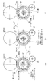
次に、図3~図7に示すように、本実施形態に係る板ガラス破砕機の使用要領について説明すると、先ず、前方へ向かって回転している後側ローラコンベア11B上に作業者(図示せず)が太陽光パネルガラスSGを背中合わせで二枚載せると、該太陽光パネルガラスSGは後側ローラコンベア11B上を進んで、破砕機本体10における上側ロール2Aと下側ロール2B間に挟み込まれて圧潰されつつ、前側ローラコンベア11A上に出てくる。そして、太陽光パネルガラスSGの後端が上側ロール2Aと下側ロール2B間に達した時点で前後のローラコンベア11A・11B並びに上側ロール2Aと下側ロール2Bを逆回転させて、太陽光パネルガラスSGを再び上側ロール2Aと下側ロール2B間に挟み込ませて再度圧潰させる。このような太陽光パネルガラスSGの上下ロール2A・2Bに対する往復移動によって太陽光パネルガラスSGにおける前記上下ロール2A・2Bの圧接部分での破砕がより綿密に行われる。そして、次に、前記往復移動させた太陽光パネルガラスSGを再度、上側ロール2Aと下側ロール2Bへ送る際には、前述した、ずらし装置30を作動させて、後側ローラコンベア11Bを左右方向に1/2ピッチだけずらせて上下ロール2A・2Bに太陽光パネルガラスSGを挟み込ませることで、太陽光パネルガラスSGおける前記往復移動で直接的圧潰されなかった部分も直接的に圧潰されるため、太陽光パネルガラスSGの全面についてより多く細かな破砕が実行される(図6、図7参照)。なお、図中BSは太陽光パネルガラスSGのバックシートを示す。
[比較試験] Next, as shown in FIGS. 3 to 7, the procedure for using the flat glass crusher according to the present embodiment will be described. First, an operator (shown) is placed on therear roller conveyor 11B rotating forward. When two solar panel glass SGs are placed back to back, the solar panel glass SG advances on the rear roller conveyor 11B and is sandwiched between the upper roll 2A and the lower roll 2B in the crusher main body 10. While being crushed, it comes out on the front roller conveyor 11A. Then, when the rear end of the solar panel glass SG reaches between the upper roll 2A and the lower roll 2B, the front and rear roller conveyors 11A and 11B and the upper roll 2A and the lower roll 2B are rotated in the reverse direction to rotate the solar panel. The glass SG is sandwiched between the upper roll 2A and the lower roll 2B again and crushed again. By such reciprocating movement of the solar panel glass SG with respect to the upper and lower rolls 2A and 2B, the solar panel glass SG is more closely crushed at the pressure-welded portion of the upper and lower rolls 2A and 2B. Next, when the reciprocated solar panel glass SG is sent to the upper roll 2A and the lower roll 2B again, the shift device 30 described above is operated to move the rear roller conveyor 11B to the left and right. By sandwiching the solar panel glass SG between the upper and lower rolls 2A and 2B by shifting the direction by 1/2 pitch, the part of the solar panel glass SG that was not directly crushed by the reciprocating movement is also directly crushed. Therefore, more fine crushing is performed on the entire surface of the solar panel glass SG (see FIGS. 6 and 7). In the figure, BS indicates a back sheet of solar panel glass SG.
[Comparative test]
[比較試験] Next, as shown in FIGS. 3 to 7, the procedure for using the flat glass crusher according to the present embodiment will be described. First, an operator (shown) is placed on the
[Comparative test]
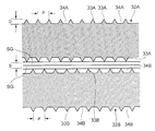
次に、前述した実施形態に係る横断面台形の凸条3A・3Bの間隔(ピッチ)Pが7mm、凸条3A・3B間の凹溝4A・4Bの深さDが14mmとなされた上下ロール2A・2Bと図13に示す横断面三角形の凸条33A・33Bであって、その間隔(ピッチ)Pを10mm、凸条33A・33B間の凹溝34A・34Bの深さDを2.5mmとした比較形態の上下ロール32A・32Bによる太陽光パネルガラスの破砕試験を実施したところ、図14に示すように、実施形態の上下ロール2A・2Bではほぼ均一で適度な細かさの粒径のガラスカレットが得られ、また図15に示すように、太陽光パネルガラスのバックシートの破損も発生せず、また図16の通り、凹溝4A・4B内への圧潰されたガラスの詰まりも全く発生しなかった。一方、比較形態の上下ロール32A・32Bでは、図17に示すように、太陽光パネルガラスのバックシートが破損してヒビわれが発生し、それがコンタミネーション(不純物)として破砕されたガラスカレットに混入していた。また、比較形態の上下ロール32A・32Bでは、図18に示すように、その凹溝34A・34B内への圧潰ガラスの詰まりが発生し、また凸条33A・33Bの摩耗も顕著であった。
Next, the upper and lower rolls having a trapezoidal cross-sectional trapezoidal protrusion 3A / 3B having a spacing (pitch) P of 7 mm and a recessed groove 4A / 4B between the protrusions 3A / 3B having a depth D of 14 mm according to the above-described embodiment. 2A and 2B and the ridges 33A and 33B having a triangular cross section shown in FIG. 13, the interval (pitch) P is 10 mm, and the depth D of the concave grooves 34A and 34B between the ridges 33A and 33B is 2.5 mm. When a crushing test of the solar panel glass was carried out using the upper and lower rolls 32A and 32B of the comparative form, as shown in FIG. 14, the upper and lower rolls 2A and 2B of the embodiment had a substantially uniform particle size and an appropriate fineness. A glass cullet was obtained, and as shown in FIG. 15, the back sheet of the solar panel glass was not damaged, and as shown in FIG. 16, the crushed glass was not clogged in the recessed grooves 4A and 4B at all. It did not occur. On the other hand, in the upper and lower rolls 32A and 32B of the comparative form, as shown in FIG. 17, the back sheet of the solar panel glass was damaged and cracks were generated, which became crushed glass cullet as contamination (impurities). It was mixed. Further, in the upper and lower rolls 32A and 32B of the comparative form, as shown in FIG. 18, the crushed glass was clogged in the concave grooves 34A and 34B, and the protrusions 33A and 33B were also significantly worn.
次に、前述したガラスカレットの粉砕機52とプレダスタ54からなるガラス粉砕装置51の詳細について説明すると、
Next, the details of the glass crusher 51 including the above-mentioned glass cullet crusher 52 and the preduster 54 will be described.
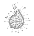
図19~図21に示すように、本実施形態に係るガラス粉砕装置51は、予め破砕されたガラスカレットを粉砕する粉砕用ロータ56が内蔵されたドラム部53を有する粉砕機52と、粉砕機52から斜め上方に伸び、前記ドラム部53内で粉砕されたガラスを誘導する略直線状の搬送用パイプ60と、搬送用パイプ60の上端が挿入された容器状のプレダスタ54と、プレダスタ54の下部に一体的に設けられたホッパ55を有している。なお、図中70は、粉砕対象である前記破砕されたガラスカレットの投入口を示す。また、前記ドラム部53の内周面にはライナ57として複数の円弧状耐摩耗性鋼板がボルト58およびナット59で固定されている。
As shown in FIGS. 19 to 21, the glass crusher 51 according to the present embodiment includes a crusher 52 having a drum portion 53 having a crushing rotor 56 for crushing a pre-crushed glass cullet, and a crusher. A substantially linear transport pipe 60 extending diagonally upward from 52 and guiding crushed glass in the drum portion 53, a container-shaped preduster 54 into which the upper end of the transport pipe 60 is inserted, and a preduster 54. It has a hopper 55 integrally provided at the lower part. In the figure, 70 indicates a slot for the crushed glass cullet to be crushed. Further, a plurality of arcuate wear-resistant steel plates are fixed as liners 57 on the inner peripheral surface of the drum portion 53 with bolts 58 and nuts 59.
なお、本実施形態において、粉砕機52に対する搬送用パイプ60の傾斜角度αは約60°である。
In the present embodiment, the inclination angle α of the transport pipe 60 with respect to the crusher 52 is about 60 °.
前記プレダスタ54は、前記搬送用パイプ60の上端60aと対向し、且つ搬送用パイプ60の軸線に対して所定角度傾斜した反射板61を有しており、搬送用パイプ60から吐出した砂状ガラス粉は前記反射板61に衝突してプレダスタ54内へ投入され、更に反射板61に衝突した後の砂状ガラス粉GSはプレダスタ54内の垂下受板91に受け止められてスムーズに落下し、前記ホッパ55内に投入される。また、プレダスタ54内に充満しているパウダー状ガラス粉GPはプレダスタ54の上部に連結されているチャンバー95内に流入した後、ダクト94およびバタフライダンパー93を経由して前記捕集機92内に捕集される(図19、図20参照)。本実施形態において、捕集機92はバグフィルタ等を具備する集塵機能を備えたものであり、当該捕集機92に捕集されたパウダー状のガラス粉は、ホッパ55に集積される砂状ガラス粉と同様、資材としてリサイクルされ得る。
The preduster 54 has a reflecting plate 61 that faces the upper end 60a of the transport pipe 60 and is inclined at a predetermined angle with respect to the axis of the transport pipe 60, and is a sandy glass discharged from the transport pipe 60. The powder collides with the reflecting plate 61 and is thrown into the preduster 54, and the sandy glass powder GS after colliding with the reflecting plate 61 is received by the hanging receiving plate 91 in the predaster 54 and falls smoothly, and the powder is smoothly dropped. It is thrown into the hopper 55. Further, the powdery glass powder GP filled in the predaster 54 flows into the chamber 95 connected to the upper part of the predaster 54, and then enters the collector 92 via the duct 94 and the butterfly damper 93. Collected (see FIGS. 19 and 20). In the present embodiment, the collector 92 is provided with a dust collecting function including a bug filter and the like, and the powdery glass powder collected by the collector 92 is sand-like accumulated in the hopper 55. Like glass powder, it can be recycled as a material.
図20に示すように、より詳細には、砂状ガラス粉GSは自重でホッパ55内へ落下し、比重が非常に軽いパウダー状ガラスGPだけが捕集機92に吸引されることとなる。なお、図中62はプレダスタ54内を目視するための窓を示す。
As shown in FIG. 20, more specifically, the sandy glass powder GS falls into the hopper 55 by its own weight, and only the powdery glass GP having a very light specific gravity is sucked into the collector 92. In the figure, 62 shows a window for visually observing the inside of the preduster 54.
図21~図24に示すように、粉砕用ロータ56は、中心に回転駆動軸63の軸受64を有する円形基板66と、円形基板66の一面に放射状に設けられた複数の粉砕板67と、各粉砕板67の端部を周回するように全粉砕板67の端部に装着されたリング状板68を備えている。
As shown in FIGS. 21 to 24, the crushing rotor 56 includes a circular substrate 66 having a bearing 64 of a rotary drive shaft 63 in the center, and a plurality of crushing plates 67 radially provided on one surface of the circular substrate 66. A ring-shaped plate 68 attached to the end of the entire crushed plate 67 is provided so as to orbit the end of each crushed plate 67.
図23~図26に示すように、前記ドラム部53の中央部分には前記回転駆動軸63が突出しており、回転駆動軸63に粉砕用ロータ56の軸受64が嵌め合わされて止めナット71によって固定されており、かかる構造によって、粉砕用ロータ56が回転自在に軸支されている。
As shown in FIGS. 23 to 26, the rotary drive shaft 63 projects from the central portion of the drum portion 53, and the bearing 64 of the crushing rotor 56 is fitted to the rotary drive shaft 63 and fixed by the stop nut 71. The crushing rotor 56 is rotatably supported by such a structure.
粉砕用ロータ56が内蔵されたドラム部53には、内蓋72が装着され、更に内蓋72の外側にヒンジ90を介して扉体73が取り付けられ、該扉体73によってドラム部53が開閉自在となされている。本実施形態では、内蓋72が粉砕用ロータ56のリング状板68と同形となされている。
An inner lid 72 is attached to the drum portion 53 in which the crushing rotor 56 is built, and a door body 73 is attached to the outside of the inner lid 72 via a hinge 90, and the drum portion 53 is opened and closed by the door body 73. It is made free. In this embodiment, the inner lid 72 has the same shape as the ring-shaped plate 68 of the crushing rotor 56.
この他、図27および図28に示すように、本実施形態では、粉砕用ロータ56の回転駆動軸63は、一対のプーリ74A・74BとベルトB、軸受81を介して電動モータMによって回転する構造となされており、且つその回転は、粉砕用ロータ56で粉砕された砂状ガラス粉が搬送用パイプ60内へ誘導されるような回転となされている。また、前記ホッパ55の下部には篩機75が設置されている。
In addition, as shown in FIGS. 27 and 28, in the present embodiment, the rotary drive shaft 63 of the crushing rotor 56 is rotated by the electric motor M via a pair of pulleys 74A and 74B, a belt B, and a bearing 81. It has a structure, and its rotation is such that the sandy glass powder crushed by the crushing rotor 56 is guided into the transport pipe 60. A sieving machine 75 is installed below the hopper 55.
次に、本実施形態に係るガラス粉砕装置51の使用方法について説明すると、電動モータMを作動させて粉砕用ロータ56を回転させた状態で、予め前記破砕機1によって破砕されたガラスカレットGCを粉砕機52の投入口70から粉砕機52内に投入することで、該ガラスカレットGCが回転している粉砕用ロータ56の粉砕板67に衝突して粉砕され、また粉砕板67に衝突した後のガラスカレットGCは、粉砕用ロータ56を囲むようにドラム部53内周面に取り付けられている耐摩耗性のライナ57に衝突することで更に粉砕され、またこのような粉砕状態においてドラム部53内を飛び交うガラスカレットGC同士が衝突する等して、前記投入口70から投入される際には鋭利な角があったガラスカレットGCは、粉砕されると共に前記鋭利な角も磨耗によって無くなり、最終的に鋭利な角がとれた細かな砂状のガラス粉GSとなる。
Next, a method of using the glass crusher 51 according to the present embodiment will be described. A glass cullet GC crushed in advance by the crusher 1 in a state where the electric motor M is operated to rotate the crushing rotor 56. By charging the glass cullet GC into the crusher 52 from the input port 70 of the crusher 52, the glass cullet GC collides with the crushing plate 67 of the rotating crushing rotor 56 and is crushed, and after colliding with the crushing plate 67. The glass cullet GC is further crushed by colliding with a wear-resistant liner 57 attached to the inner peripheral surface of the drum portion 53 so as to surround the crushing rotor 56, and the drum portion 53 is further crushed in such a crushed state. The glass cullet GC, which had sharp corners when it was thrown in from the slot 70 due to collision between the glass cullet GCs flying inside, was crushed and the sharp corners disappeared due to wear, and finally. It becomes a fine sandy glass powder GS with sharp edges.
また、前記粉砕用ロータ56の回転に伴ってドラム部53内にはガラスカレットGCを巻き上げる旋回空気渦流が発生しており、前述した粉砕によって、外形が数ミリ程度にまで粉砕された細かい砂状ガラス粉GSは前記巻き上げ空気渦流によって、搬送用パイプ60内を上昇してプレダスタ54へ誘導される。この際、搬送用パイプ60は、略直接状であるため、前記砂状ガラス粉GCは搬送途中に淀みなく、何らの抵抗もなく、スムーズにプレダスタ54内に進入する。そして、プレダスタ54内では、前記搬送用パイプ60の上端と対向して配設されている傾斜状の反射板61に、前記進入してきた砂状ガラス粉GSが衝突し、更に反射板61に、衝突した後の砂状ガラス粉GSは、プレダスタ54内の垂下受板91に受け止められて下方に落下し、最終的にプレダスタ54下方のホッパ55に前記砂状ガラス粉GSが落下する。そして、砂状ガラス粉GSはホッパ55から前記篩機75へ流入する。
Further, a swirling air vortex that winds up the glass cullet GC is generated in the drum portion 53 with the rotation of the crushing rotor 56, and the outer shape is crushed to about several millimeters by the above-mentioned crushing. The glass powder GS rises in the transport pipe 60 and is guided to the preduster 54 by the hoisting air vortex. At this time, since the transport pipe 60 has a substantially direct shape, the sandy glass powder GC smoothly enters the preduster 54 without stagnation during transport and without any resistance. Then, in the preduster 54, the sandy glass powder GS that has entered collides with the inclined reflective plate 61 arranged so as to face the upper end of the transport pipe 60, and further, the reflective plate 61 is subjected to the collision. The sandy glass powder GS after the collision is received by the hanging receiving plate 91 in the preduster 54 and falls downward, and finally the sandy glass powder GS falls on the hopper 55 below the predaster 54. Then, the sandy glass powder GS flows from the hopper 55 into the sieving machine 75.
一方、ドラム部53内で十分に粉砕されていないガラスカレットGCは、前記粉砕用ロータ56の回転に伴うドラム部53内の巻き上げ旋回空気渦流によって上昇せずに自重で落下すると共に再び粉砕用ロータ56の粉砕板67に衝突したり、その反動でライナ57に衝突し、また前記ガラスカレットGC同士の衝突によって更に粉砕化されるのである。そして、このような粉砕化の繰り返しによって外形が数ミリ程度にまで粉砕された細かい砂状ガラス粉GSになった時に、該砂状ガラス粉GSが前記粉砕用ロータ56の回転に伴うドラム部53内の巻き上げ旋回空気渦流によって上昇して搬送用パイプ60内へ導かれるのである。
On the other hand, the glass cullet GC that has not been sufficiently crushed in the drum portion 53 does not rise due to the hoisting swirling air vortex in the drum portion 53 accompanying the rotation of the crushing rotor 56, but falls by its own weight and again the crushing rotor. It collides with the crushed plate 67 of 56, collides with the liner 57 due to the reaction thereof, and is further pulverized by the collision between the glass cullet GCs. Then, when the fine sandy glass powder GS whose outer shape is crushed to about several millimeters is obtained by repeating such crushing, the sandy glass powder GS becomes the drum portion 53 accompanying the rotation of the crushing rotor 56. It rises by the winding swirling air vortex inside and is guided into the transport pipe 60.
本発明に係るリサイクル方法およびリサイクルシステムによれば、板ガラスから一定粒度の砂状ガラス粉が容易且つ確実に得られるため、太陽光パネルガラス、自動車ガラス、窓ガラスおよび遊戯機ガラス等として使用された板ガラスを資源化の分野において、幅広い利用が期待できる。
According to the recycling method and recycling system according to the present invention, since sandy glass powder having a certain particle size can be easily and surely obtained from flat glass, it has been used as solar panel glass, automobile glass, window glass, amusement machine glass and the like. Widespread use of flat glass can be expected in the field of recycling.
1 板ガラス破砕機
2A 上側ロール
2B 下側ロール
3A・3B 凸条
4A・4B 凹溝
6 押えローラ
10 破砕機本体
11A・11B ローラコンベア
21 破砕機用捕集機
25 偏心リング
30 コンベアずらし装置
SG 板ガラス
51 ガラス粉砕装置
52 ガラス粉砕機
53 ドラム部
54 プレダスタ
55 ホッパ
56 粉砕用ロータ
60 搬送用パイプ
61 反射板
75 篩機
92 プレダスタ用捕集機 1Plate glass crusher 2A Upper roll 2B Lower roll 3A / 3B Convex 4A / 4B Concave groove 6 Presser roller 10 Crusher body 11A / 11B Roller conveyor 21 Crusher collector 25 Eccentric ring 30 Conveyor shifter SG plate glass 51 Glass crusher 52 Glass crusher 53 Drum part 54 Preduster 55 Hopper 56 Crushing rotor 60 Transport pipe 61 Reflector 75 Sieve machine 92 Preduster collector
2A 上側ロール
2B 下側ロール
3A・3B 凸条
4A・4B 凹溝
6 押えローラ
10 破砕機本体
11A・11B ローラコンベア
21 破砕機用捕集機
25 偏心リング
30 コンベアずらし装置
SG 板ガラス
51 ガラス粉砕装置
52 ガラス粉砕機
53 ドラム部
54 プレダスタ
55 ホッパ
56 粉砕用ロータ
60 搬送用パイプ
61 反射板
75 篩機
92 プレダスタ用捕集機 1
Claims (13)
- 板ガラスを破砕してガラスカレットを得る板ガラス破砕工程と、該工程で得られたガラスカレットを砂状ガラス粉に粉砕するガラスカレット粉砕工程を有する、板ガラスのリサイクル方法。 A method for recycling flat glass, which comprises a flat glass crushing step of crushing flat glass to obtain glass cullet and a glass cullet crushing step of crushing the glass cullet obtained in the step into sandy glass powder.
- 更に、ガラスカレット粉砕工程で得られた砂状ガラス粉を篩分けする砂状ガラス粉篩分け工程を有する、請求項1記載の板ガラスのリサイクル方法。 The method for recycling flat glass according to claim 1, further comprising a sandy glass powder sieving step for sieving the sandy glass powder obtained in the glass cullet crushing step.
- 更に、ガラス粉篩分け工程で所定粒度より大きい砂状ガラス粉をガラスカレット粉砕工程に戻して再粉砕するガラス粉粉砕工程を有する、請求項1または請求項2記載の板ガラスのリサイクル方法。 The plate glass recycling method according to claim 1 or 2, further comprising a glass powder crushing step of returning sandy glass powder larger than a predetermined particle size to a glass cullet crushing step and re-grinding in the glass powder sieving step.
- 板ガラス破砕工程におけるガラスカレットの外形が、15mm以下である、請求項1~請求項3のうちのいずれか一項記載の板ガラスのリサイクル方法。 The method for recycling flat glass according to any one of claims 1 to 3, wherein the outer shape of the glass cullet in the flat glass crushing step is 15 mm or less.
- ガラスカレット粉砕工程で得られる砂状ガラス粉の粒度が、0.3~5mmの範囲内である、請求項1~請求項4のうちのいずれか一項記載の板ガラスのリサイクル方法。 The method for recycling flat glass according to any one of claims 1 to 4, wherein the particle size of the sandy glass powder obtained in the glass cullet crushing step is within the range of 0.3 to 5 mm.
- 更に、板ガラス破砕工程とガラスカレット粉砕工程の一方または両方の工程で、発生するガラス粉塵を捕集するガラス粉塵捕集工程を有する、請求項1~請求項5のうちのいずれか一項記載の板ガラスのリサイクル方法。 The invention according to any one of claims 1 to 5, further comprising a glass dust collecting step of collecting generated glass dust in one or both of the plate glass crushing step and the glass cullet crushing step. How to recycle flat glass.
- 板ガラス破砕工程が、板ガラスを圧潰する一対の破砕ロールを備えたガラス破砕機によって行われることを特徴とする、請求項1~請求項6のうちのいずれか一項記載の板ガラスのリサイクル方法。 The method for recycling plate glass according to any one of claims 1 to 6, wherein the plate glass crushing step is performed by a glass crusher provided with a pair of crushing rolls for crushing the plate glass.
- ガラスカレット粉砕工程が、ドラム部内でガラスカレットを衝突粉砕する粉砕用ロータを備えたガラス粉砕機と、ガラス粉砕機から伸びる搬送用パイプを介して前記粉砕用ロータの風圧で飛散搬送される砂状ガラス粉を衝突粉砕する反射板を備えたプレダスタとによって行われることを特徴とする、請求項1~請求項7のうちのいずれか一項記載の板ガラスのリサイクル方法。 The glass cullet crushing step is a sandy state in which the glass cullet is scattered and conveyed by the wind pressure of the crushing rotor via a glass crusher provided with a crushing rotor for colliding and crushing the glass cullet in the drum portion and a transport pipe extending from the glass crusher. The method for recycling flat glass according to any one of claims 1 to 7, wherein the method is performed by a preduster provided with a reflecting plate for colliding and pulverizing glass powder.
- 板ガラスが太陽光パネルガラスであって、太陽光パネルにおける板ガラスの破砕工程後に太陽光パネルのモジュールを排除して、ガラスカレットのみを粉砕することを特徴とする、請求項1~請求項8のうちのいずれか一項記載の板ガラスのリサイクル方法。 Of claims 1 to 8, wherein the flat glass is a solar panel glass, and after the step of crushing the flat glass in the solar panel, the module of the solar panel is eliminated and only the glass cullet is crushed. The method for recycling flat glass according to any one of the above.
- 請求項1~請求項9のうちのいずれか一項記載の板ガラスリサイクル方法に使用する板ガラスリサイクルシステムであって、板ガラスを破砕してガラスカレットを得る板ガラス破砕工程を実行する板ガラス破砕機と、該工程で得られたガラスカレットを砂状ガラス粉に粉砕するガラスカレット粉砕工程を実行するガラス粉砕装置を備え、板ガラス破砕機は、互いに対向する上側ロールと下側ロールとからなる上下一対の板ガラス破砕ロール並びに前記上側ロールの前側および後側にそれぞれ設けられた押えロールを有する破砕機本体と、破砕機本体の前側および後側にそれぞれ設けられたローラコンベアを有し、前記上側ロールおよび下側ロールにはその軸線方向と直交する方向に所定間隔をあけて横断面方形の凸条が周設され、且つ上側ロールと下側ロールの凸条は互い違いに配設されている、板ガラスリサイクルシステム。 A flat glass recycling system used in the flat glass recycling method according to any one of claims 1 to 9, wherein a flat glass crusher that executes a flat glass crushing step of crushing flat glass to obtain a glass cullet and the above-mentioned flat glass crusher. A glass cullet crushing device for executing a glass cullet crushing step of crushing the glass cullet obtained in the process into sandy glass powder is provided, and the plate glass crusher is a pair of upper and lower plate glass crushers composed of an upper roll and a lower roll facing each other. The upper roll and the lower roll have a crusher main body having a presser roll provided on the front side and the rear side of the roll and the upper roll, respectively, and roller conveyors provided on the front side and the rear side of the crusher main body, respectively. A flat glass recycling system in which ridges having a rectangular cross section are provided around the glass at predetermined intervals in a direction orthogonal to the axial direction, and the ridges of the upper roll and the lower roll are arranged alternately.
- 板ガラス破砕機の上下ロールの凸条が先端側に向かって幅が狭い横断面台形となされている、請求項10記載の板ガラスリサイクルシステム。 The plate glass recycling system according to claim 10, wherein the ridges of the upper and lower rolls of the plate glass crusher have a trapezoidal cross section that narrows toward the tip side.
- ガラス粉砕装置は、予め破砕されたガラスカレットを粉砕する粉砕用ロータが内蔵されたドラム部を有する粉砕機と、粉砕機から斜め上方に伸び、前記ドラム部内で粉砕された砂状ガラス粉を誘導する略直線状の搬送用パイプと、搬送用パイプの上端が挿入された容器状のプレダスタとを有し、プレダスタが、前記搬送用パイプの上端と対向し、且つ搬送用パイプの上端から吐出する砂状ガラス粉をプレダスタ内へ誘導する反射板を備えている、請求項10または請求項11記載の板ガラスリサイクルシステム。 The glass crusher has a crusher having a drum portion with a built-in crushing rotor for crushing pre-crushed glass cullet, and extends diagonally upward from the crusher to induce crushed sandy glass powder in the drum portion. It has a substantially linear transport pipe and a container-shaped preduster into which the upper end of the transport pipe is inserted, and the preduster faces the upper end of the transport pipe and discharges from the upper end of the transport pipe. The flat glass recycling system according to claim 10 or 11, further comprising a reflector that guides sandy glass powder into the preduster.
- 更に、板ガラス破砕機とプレダスタの一方または両方にガラス粉塵を捕集するガラス粉塵捕集機が付設されている、請求項10~請求項12のうちのいずれか一項記載の板ガラスリサイクルシステム。 The flat glass recycling system according to any one of claims 10 to 12, further comprising a glass dust collector for collecting glass dust on one or both of the flat glass crusher and the preduster.
Priority Applications (2)
| Application Number | Priority Date | Filing Date | Title |
|---|---|---|---|
| PCT/JP2020/014135 WO2021192254A1 (en) | 2020-03-27 | 2020-03-27 | Method and system for recycling sheet glass |
| JP2020545810A JP6857889B1 (en) | 2020-03-27 | 2020-03-27 | Flat glass recycling method and recycling system |
Applications Claiming Priority (1)
| Application Number | Priority Date | Filing Date | Title |
|---|---|---|---|
| PCT/JP2020/014135 WO2021192254A1 (en) | 2020-03-27 | 2020-03-27 | Method and system for recycling sheet glass |
Publications (1)
| Publication Number | Publication Date |
|---|---|
| WO2021192254A1 true WO2021192254A1 (en) | 2021-09-30 |
Family
ID=75378010
Family Applications (1)
| Application Number | Title | Priority Date | Filing Date |
|---|---|---|---|
| PCT/JP2020/014135 WO2021192254A1 (en) | 2020-03-27 | 2020-03-27 | Method and system for recycling sheet glass |
Country Status (2)
| Country | Link |
|---|---|
| JP (1) | JP6857889B1 (en) |
| WO (1) | WO2021192254A1 (en) |
Cited By (1)
| Publication number | Priority date | Publication date | Assignee | Title |
|---|---|---|---|---|
| EP4169619A1 (en) * | 2021-10-21 | 2023-04-26 | Erutec GmbH | Method and device for treating photovoltaic modules |
Citations (9)
| Publication number | Priority date | Publication date | Assignee | Title |
|---|---|---|---|---|
| US5950936A (en) * | 1998-01-21 | 1999-09-14 | Bergart; David | Process and system for recycling glass |
| JP2002186952A (en) * | 2000-12-20 | 2002-07-02 | Central Glass Co Ltd | Equipment for separating laminated glass into glass fragment and intermediate film fragment and recovering them |
| JP2004181321A (en) * | 2002-12-02 | 2004-07-02 | Yasushi Shimomura | Method and apparatus for separating safety glass or laminated glass into glass and film to recover glass and film |
| JP2004216234A (en) * | 2003-01-10 | 2004-08-05 | Nippon Sheet Glass Co Ltd | Recycling method of waste vitreous material and glass cullet manufactured by the method |
| JP2004269278A (en) * | 2003-03-05 | 2004-09-30 | Honda Motor Co Ltd | Method and apparatus for separating laminated glass |
| JP2011183243A (en) * | 2010-03-04 | 2011-09-22 | Panasonic Corp | Method and system for recycling glass |
| JP2013223841A (en) * | 2012-04-23 | 2013-10-31 | Sharp Corp | Recycling method of flat panel |
| JP2015205249A (en) * | 2014-04-22 | 2015-11-19 | 株式会社環境保全サービス | Glass separation apparatus |
| JP2016203128A (en) * | 2015-04-28 | 2016-12-08 | 株式会社環境保全サービス | Glass separator |
Family Cites Families (1)
| Publication number | Priority date | Publication date | Assignee | Title |
|---|---|---|---|---|
| US4795103A (en) * | 1987-05-21 | 1989-01-03 | Lech Stanley J | Pulverizing apparatus |
-
2020
- 2020-03-27 JP JP2020545810A patent/JP6857889B1/en active Active
- 2020-03-27 WO PCT/JP2020/014135 patent/WO2021192254A1/en active Application Filing
Patent Citations (9)
| Publication number | Priority date | Publication date | Assignee | Title |
|---|---|---|---|---|
| US5950936A (en) * | 1998-01-21 | 1999-09-14 | Bergart; David | Process and system for recycling glass |
| JP2002186952A (en) * | 2000-12-20 | 2002-07-02 | Central Glass Co Ltd | Equipment for separating laminated glass into glass fragment and intermediate film fragment and recovering them |
| JP2004181321A (en) * | 2002-12-02 | 2004-07-02 | Yasushi Shimomura | Method and apparatus for separating safety glass or laminated glass into glass and film to recover glass and film |
| JP2004216234A (en) * | 2003-01-10 | 2004-08-05 | Nippon Sheet Glass Co Ltd | Recycling method of waste vitreous material and glass cullet manufactured by the method |
| JP2004269278A (en) * | 2003-03-05 | 2004-09-30 | Honda Motor Co Ltd | Method and apparatus for separating laminated glass |
| JP2011183243A (en) * | 2010-03-04 | 2011-09-22 | Panasonic Corp | Method and system for recycling glass |
| JP2013223841A (en) * | 2012-04-23 | 2013-10-31 | Sharp Corp | Recycling method of flat panel |
| JP2015205249A (en) * | 2014-04-22 | 2015-11-19 | 株式会社環境保全サービス | Glass separation apparatus |
| JP2016203128A (en) * | 2015-04-28 | 2016-12-08 | 株式会社環境保全サービス | Glass separator |
Cited By (1)
| Publication number | Priority date | Publication date | Assignee | Title |
|---|---|---|---|---|
| EP4169619A1 (en) * | 2021-10-21 | 2023-04-26 | Erutec GmbH | Method and device for treating photovoltaic modules |
Also Published As
| Publication number | Publication date |
|---|---|
| JPWO2021192254A1 (en) | 2021-09-30 |
| JP6857889B1 (en) | 2021-04-14 |
Similar Documents
| Publication | Publication Date | Title |
|---|---|---|
| CN207628480U (en) | A kind of broken screening plant of construction waste | |
| CN109926193A (en) | A kind of broken sorting Integrated Processing Unit for building waste | |
| CN109967494B (en) | Process method and system device for treating construction waste | |
| CN210171550U (en) | Industrial solid waste crushed material sorting device | |
| CN212069525U (en) | Dry method machine-made sandstone screening device | |
| CN111604116A (en) | Cement clinker raw material efficient crusher with screening function | |
| WO2021192254A1 (en) | Method and system for recycling sheet glass | |
| CN114234625A (en) | Rotary kiln residue treatment device | |
| CN219291506U (en) | Crushing and screening integrated machine | |
| CN112916115A (en) | Construction waste treatment device | |
| CN113117797A (en) | Waste treatment device for civil engineering construction | |
| US5238195A (en) | Method for recycling wallboard | |
| CN112371908A (en) | Casting waste residue recovery device | |
| KR20070071192A (en) | The sand waste sorter use to teeth of a comb attaching conveyor | |
| CN114101273B (en) | Recycling processing method of construction waste | |
| CN212595971U (en) | Construction waste recycling device | |
| CN215353670U (en) | Sorting device for treating construction waste | |
| CN209753089U (en) | Construction waste recycling device | |
| CN111468222B (en) | Building rubbish is with categorised sieving mechanism | |
| WO2000071257A1 (en) | Reducer and separator for preparing gypsum board and other products for recycling | |
| KR20030051484A (en) | Dry type sand producing apparatus system and the method threrof | |
| CN213222541U (en) | Screening and crushing device for solid waste | |
| KR100705773B1 (en) | Shreder for industrial waste and disused car | |
| CN109012984B (en) | Glass fragment crushing and screening device | |
| KR200236742Y1 (en) | Apparatus for Recycling of Concrete Scrapped Material |
Legal Events
| Date | Code | Title | Description |
|---|---|---|---|
| ENP | Entry into the national phase |
Ref document number: 2020545810 Country of ref document: JP Kind code of ref document: A |
|
| 121 | Ep: the epo has been informed by wipo that ep was designated in this application |
Ref document number: 20927122 Country of ref document: EP Kind code of ref document: A1 |
|
| NENP | Non-entry into the national phase |
Ref country code: DE |
|
| 122 | Ep: pct application non-entry in european phase |
Ref document number: 20927122 Country of ref document: EP Kind code of ref document: A1 |