WO2021192209A1 - エレベーターの位置検出装置とそれを用いたエレベーターの制御システム - Google Patents
エレベーターの位置検出装置とそれを用いたエレベーターの制御システム Download PDFInfo
- Publication number
- WO2021192209A1 WO2021192209A1 PCT/JP2020/013943 JP2020013943W WO2021192209A1 WO 2021192209 A1 WO2021192209 A1 WO 2021192209A1 JP 2020013943 W JP2020013943 W JP 2020013943W WO 2021192209 A1 WO2021192209 A1 WO 2021192209A1
- Authority
- WO
- WIPO (PCT)
- Prior art keywords
- car
- cable
- sensor
- curved portion
- elevator
- Prior art date
- Legal status (The legal status is an assumption and is not a legal conclusion. Google has not performed a legal analysis and makes no representation as to the accuracy of the status listed.)
- Ceased
Links
Images


Classifications
-
- B—PERFORMING OPERATIONS; TRANSPORTING
- B66—HOISTING; LIFTING; HAULING
- B66B—ELEVATORS; ESCALATORS OR MOVING WALKWAYS
- B66B3/00—Applications of devices for indicating or signalling operating conditions of elevators
- B66B3/02—Position or depth indicators
-
- B—PERFORMING OPERATIONS; TRANSPORTING
- B66—HOISTING; LIFTING; HAULING
- B66B—ELEVATORS; ESCALATORS OR MOVING WALKWAYS
- B66B7/00—Other common features of elevators
- B66B7/06—Arrangements of ropes or cables
Definitions
- the present disclosure relates to an elevator position detection device that detects the position of an elevator car and an elevator control system using the device.
- the present invention relates to an elevator position detecting device that can be used to detect the position of a car near the terminal floor of the elevator.
- a position detection switch provided in the car in advance is provided near the terminal floor of the hoistway. It is configured to engage with the cam. Further, the position detection switch engaged with the cam is configured to operate at each of a plurality of operating points provided in advance on the cam.
- the positions of the plurality of operating points and the value of the overspeed level at each operating point at this time are obtained when the overspeed state is detected by the corresponding overspeed level at each operating point position and the brake is activated. It is determined by designing the car to collide with, for example, a shock absorber arranged on the floor of the hoistway at a collision speed equal to or lower than the allowable collision speed of the shock absorber (see, for example, Patent Document 1).
- the conventional elevator position detecting device disclosed in Patent Document 1 has the following problems. That is, in this conventional elevator position detection device, for example, it is necessary to appropriately adjust the relative positions of the switch and the cam according to the rated speed of the elevator, but there is a problem that this position adjustment work takes time. there were. This is because, in order to sufficiently decelerate the car at the end of the hoistway, the higher the rated speed of the elevator, the more it is necessary to check the speed of the car at a position farther from the end. This increases the overall length of the cam required by conventional elevator position detectors to set the operating point for detecting the position of the car far from the end, resulting in even a small amount of cam. Since the position of the operating point changes significantly when tilted, it was not easy to adjust the relative position between the switch and the cam.
- any of the vertical directions is used to start the subsequent ascending / descending motion.
- Adopt a structure that can keep the switch and cam engaged so as not to lose the car position information, which is necessary to determine whether the car should be driven in the direction or whether the car can be driven. I needed it. Therefore, it is necessary for the elevator position detection device, etc. according to the present disclosure to be able to cope with the problem of loss of car position information in order to realize a safe ascending / descending motion of the car.
- An object of the present invention is to provide an elevator position detection device that does not place much burden on the installation adjustment work of the position detection device according to the rated speed of the elevator. In addition, it is to provide an elevator position detection device that can deal with the problem of loss of car position information due to power cutoff or power failure. Furthermore, it is to provide an elevator control system using the position detection device of these elevators.
- the position detection device for an elevator has one end fixed to a device provided in the hoistway and the other end fixed to a car that moves up and down in the hoistway, and the lower end is suspended in a U shape.
- a belt-shaped cable having a curved portion formed at a position and a cable covering portion of the cable provided at least at the curved portion, and a change in physical quantity due to bending deformation along the cable at the provided portion. Obtained from measurement results by a sensor that can be measured and a sensor that has been measured in advance when sensors are provided at multiple locations along the cable at the curved portion when the car is in a predetermined car position.
- the position of the curved part of the cable at the present time is estimated based on the measurement result by the sensor when the car is at the current position of the car, and it corresponds to the estimated position of the curved part of the cable at the present time. It is characterized in that it is provided with a car position calculation unit for calculating the current position of the car, which is determined by the above.
- the elevator control system includes an elevator position detection device according to the present disclosure and a control unit that controls the ascending / descending motion of the car, and the control unit is calculated by the car position calculation unit at the present time. It is characterized in that the ascending / descending motion of the car is controlled by using the position of the car.
- the elevator control system includes an elevator position detection device according to the present disclosure and an elevator control unit that controls the elevating motion of the car, and the control unit is a rotation angle of a motor that drives the car up and down.
- one end is fixed to the equipment provided in the hoistway, and the other end is fixed to the car that moves up and down in the hoistway.
- a belt-shaped cable in which a curved portion is formed at the lower end position in a state of being suspended in a shape, and a cable provided at least at the curved portion of the cable covering portion of the cable, and the cable at the provided portion.
- the car position calculation unit determines the position of the curved part in the cable at the present time with respect to the measurement result by the sensor when the car is in the current car position. Can be estimated, and the current position of the car, which is determined according to the estimated position of the curved portion of the cable at the present time, can be calculated.
- the position detection device in which the car is particularly effective at or near the end of the hoistway is less burdened with the appropriate installation adjustment work according to the rated speed of the elevator. It plays.
- the ascending / descending motion is started after the latest car position information cannot be specified due to a power failure state or interruption of power supply by the power supply device.
- the car position information which is the calculation result of the car position calculation unit in the elevator position detection device according to the present disclosure, can be used by the control unit in the elevator control system as information instead of the latest car position information. Therefore, for example, even if the elevator stops in the vicinity of the terminal floor due to a power failure or the power supply is cut off by the power supply device and the car position information is lost, the elevator can be promptly started to move up and down. It is possible to determine in which direction the car 4 should be driven in the vertical direction, or whether the car can be driven. As a result, it is possible to realize a safe ascending / descending motion of the car at the start of the ascending / descending motion.
- FIG. 5 is an image diagram of the entire elevator system for explaining an elevator position detection device and an elevator control system using the elevator position detection device according to the first embodiment. It is a figure for demonstrating the outline of the structure of the position detection device of an elevator which concerns on Embodiment 1.
- FIG. It is a figure which shows an example of the position spacing on a cable about the sensor which constitutes the position detection device of an elevator which concerns on Embodiment 1 of this disclosure. It is a figure for demonstrating the basic idea about the calculation principle of the car position calculation part in the position detection device of an elevator which concerns on Embodiment 1.
- FIG. It is a figure which shows the measurement result by the sensor handled by the car position calculation part in the position detection device of an elevator which concerns on Embodiment 1.
- FIG. 1 It is a figure for demonstrating the pattern matching using the one-dimensional data string obtained from the measurement result by a sensor, which is executed by the car position calculation part in the position detection device of an elevator which concerns on Embodiment 1.
- FIG. It is a figure for demonstrating the outline of the structure of the position detection device of an elevator which concerns on Embodiment 2.
- FIG. It is a figure for demonstrating the outline of the structure of the position detection device of an elevator which concerns on Embodiment 3.
- the content represented by the "department” is not limited to physical means, but also includes the case where the function of the "department” is realized by software. Further, the function of one "part” may be realized by two or more physical means or devices. Further, the functions of two or more “parts” may be realized by one physical means or device.
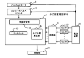
- FIG. 1 is an image diagram of the entire elevator system for explaining an elevator position detection device and an elevator control system using the elevator position detection device according to the first embodiment. Further, FIG. 2 is a diagram for explaining an outline of the configuration of the elevator position detecting device according to the first embodiment.
- the pulse encoder 8, the encoder pulse counter 9, the power supply device 20, and the control unit 21 shown in FIG. 2 do not necessarily have to be included in the configuration of the elevator position detection device according to the first embodiment.
- the configuration of the elevator control system according to the first embodiment of the present disclosure is such that the control unit 21 shown in FIG. 2 is added to the configuration of the elevator position detection device according to the first embodiment.
- a balance weight 3 is connected to one end of a rope 2 wound around a sheave 1, and a car 4 is connected to the other end.
- a hoist (not shown) connected to the sheave 1 is used to move the car 4 up and down.
- the hoisting machine is rotationally driven by a motor (not shown).
- the balance weight 3 moves up and down in the direction opposite to the direction of the up and down movement of the car 4.
- the car 4, the balance weight 3, the sheave 1 and the rope 2 described here are the basic configurations of the mechanical system of the elevator.
- a control cable 7 and a hoistway device 6, which will be described later, may be further included as a configuration of an elevator mechanical system.
- the mechanical systems of these elevators are installed in the hoistway 31 as shown in FIG.
- An elevator position detection device and an elevator control system using the elevator position detection device according to the first embodiment are applied to the elevator mechanical system.
- FIG. 1 shows a case where the other end of the cable 7 is particularly fixed to the lower part of the car 4.
- the belt-shaped cable 7 is suspended in a U-shape. Further, a curved portion is formed at the lower end position of the belt-shaped cable 7.
- a sensor 10 capable of measuring a change is provided at least in this curved portion.
- the sensor 10 is shown as a black circle on the cable.
- the sensor 10 may be further provided in the cable covering portion other than the curved portion of the cable 7.
- a pressure-sensitive conductive rubber having a characteristic that the resistance value changes with respect to bending deformation can be used.
- This type of pressure-sensitive conductive rubber is disclosed in, for example, International Publication WO2011 / 065100.
- a strain gauge having a characteristic that the resistance value changes with respect to bending deformation can be similarly used.
- the lower end position of the belt-shaped cable 7 when the car 4 is near the terminal floor It is effective to provide a plurality of sensors 10 on the inner or outer covering surface of the cable 7 at the portion corresponding to the curved portion to be formed.
- the hoistway device 6 described above is an electric device including a power supply device 20 that supplies power to the sensor 10.
- FIG. 1 shows a case where a belt-shaped cable 7 is used for detecting the position of the car.
- the hoistway device 6 and the car 4 (electrical device in the car) shown in FIG. 1 are used for power supply and communication by transmitting and receiving signals.
- the control cable 75 may be used.
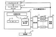
- FIG. 2 is a diagram for explaining the outline of the configuration of the elevator position detecting device according to the first embodiment.
- the pulse encoder 8 is supplied with power by the power supply device 20 and outputs a pulse indicating the rotation angle of the motor for realizing the ascending / descending motion of the car 4.
- the encoder counter 9 is similarly supplied with power by the power supply device 20, and outputs a value obtained by counting the pulses output from the pulse encoder 8 as information necessary for obtaining the position of the car 4 that moves up and down in the hoistway. do.
- an encoder indicating the rotation angle of the motor for realizing the ascending / descending motion of the car 4 in addition to the pulse encoder 8, there is also an absolute encoder whose absolute position can be detected.
- the encoder that is commonly used as an elevator system is the pulse encoder 8.
- the information obtained by using the pulse encoder 8 and the encoder counter 9 will be simply referred to as the output information of the pulse encoder 8 without giving a misunderstanding.
- the control unit 21 shown in FIG. 2 can obtain the latest car position information stored based on the output information of the pulse encoder 8 and the current car position information at the present time.
- the absolute position of the car 4 can be obtained, and the ascending / descending motion control of the car 4 is realized.
- the car position information is not lost when the elevator is emergency stopped near the terminal floor due to a power supply cutoff or a power failure. , It was necessary to adopt a structure that can maintain the engaged state of the switch and the cam. If the car position information is lost, it becomes unclear in which direction the car 4 should be driven in the vertical direction or whether the car 4 can be driven when the subsequent restoration operation is started.
- the position detection device of the elevator has adopted the above-mentioned structure in order to realize a safe up-and-down movement of the car 4.
- the sensor 10 is, in particular, a pressure-sensitive conductive rubber having a characteristic that the electric resistance value changes with respect to bending deformation. Further, here, the electric resistance value of the sensor 10 shows a large value when the bending deformation of the cable is large. As described above, the electrical resistance value of the sensor 10 changes with respect to bending deformation. Specifically, the electrical resistance value of the sensor 10 shows a large value as a result because the distortion due to bending increases as the curvature of bending increases. On the other hand, the electric resistance value of the sensor 10 shows a small value as a result because the distortion due to bending becomes smaller as the curvature of bending becomes smaller.
- the reading unit 11 is located in the hoistway device 6 provided in the hoistway 31, and reads the current value flowing through each of the plurality of sensors 10.
- the car position estimation unit 12 performs signal processing using the electrical resistance value converted from the current value read by the reading unit 11 as a parameter.
- This electric resistance value is specifically converted from the current value read by the reading unit 11, for example, as follows.
- the current value flowing through the series circuit and the electrical resistance value of the sensor 10 are calculated. can.
- the current value flowing in this series circuit becomes the current value flowing in each of the plurality of sensors 10.
- FIG. 3 is a diagram showing an example of the position spacing on the cable for the sensors constituting the position detection device of the elevator according to the first embodiment.
- the position spacing of the sensors 10 on the cable 7 as shown in FIG. 3 can be determined from the viewpoint of the car position detection accuracy required by the elevator system.
- the required car position detection accuracy changes according to each function such as landing control of the car 4 and deceleration control of the terminal floor, which should be realized. Therefore, the position spacing of the sensors 10 on the cable 7 is preferably, for example, about 20 mm to 500 mm.
- the positions of the sensors 10 on the cable 7 do not necessarily have to be evenly spaced, but are preferably evenly spaced from the viewpoint of convenience.
- the car position estimation unit 12 includes an initial setting unit 15, a database 13, and a car position calculation unit 14.
- the initial setting unit 15 determines a change in physical quantity with respect to bending deformation of the sensor 10 when the sensors 10 are provided at a plurality of curved portions when the car 4 is located at a predetermined car position.
- the software realizes the function of executing the processing required for measurement.
- the initial setting unit 15 determines whether or not there is a car 4 at a predetermined car position by using the output result of the encoder counter 9, and measures by the sensor 10 at that time according to the determination result. A process of whether or not to obtain the result via the reading unit 11 is performed. Specifically, the measurement result by the sensor 10 at the curved portion of the cable 7 when the car 4 is located at a predetermined position is stored in the database 13.
- the database 13 is the measurement result by the sensor 10 measured in advance at the curved portion of the cable 7 when the car 4 is in the predetermined position as the information related to the predetermined position. And a predetermined position are memorized.
- the car position calculation unit 14 is based on the measurement results of the sensors measured in advance when the sensors 10 are provided at a plurality of locations along the cable of the curved portion when the car 4 is located at a predetermined car position. Based on the obtained database 13, the position of the curved portion in the cable 7 at the present time is estimated with respect to the measurement result by the sensor 10 when the car 4 is in the car position at the present time, and the estimated position of the curved portion in the cable 7 at the present time is used. The position of the car 4 at the present time, which is determined according to the position of the curved portion, is calculated.
- the predetermined position which is the determination condition for storing in the database 13, is assumed to be the case where the car 4 is on the terminal floor or near the terminal floor.
- the first car position is used as a reference position and the car 4 is on the terminal floor or near the terminal floor.
- the database 13 has the one-dimensional data string as the measurement result by the sensor 10 when the car 4 is in the first position, and the first position as a predetermined position. And shall be memorized.
- the shape of the curved portion formed at the lower end position of the cable 7 in the suspended state is a property that does not depend on the car position. It can be seen that the predetermined car position does not have to be limited to the case where the car 4 is on the terminal floor or near the terminal floor as described here. That is, it can be seen that the predetermined car position may be any car position of the car 4.
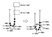
- FIG. 4 is a diagram for explaining a basic concept regarding the calculation principle of the car position calculation unit 14 in the elevator position detection device according to the first embodiment.
- the left figure simultaneously shows the curved portion of the cable 7 when the car 4 is in the first position and the second position, respectively.
- the position of the car 4 shown by the solid line above is the second position.
- the position of the car 4 shown by the broken line at the bottom is the first position.
- the senor 10 is provided at least at a position where the sensor 10 is provided at a plurality of predetermined positions along the cable 7 in the cable covering portion of the curved portion, and the sensor 10 is subjected to bending deformation at each location. It can measure changes in physical quantities.
- the position of the sensor 10 is indicated by a black circle and a white circle in the left figure in FIG. It should be noted that the position of the sensor 10 is more accurately assumed to be, for example, inside the cable covering portion. In addition, it may be on the outside of the cable sheath.
- the black circle in the left figure in FIG. 4 indicates the position of the sensor 10 when the position of the car 4 is in the second position shown by the solid line.
- the white circle in the left figure in FIG. 4 indicates the position of the sensor 10 when the position of the car 4 is in the first position indicated by the broken line.
- the black circle indicating that the car 4 is in the second position is also the car 4.
- the white circle indicating that is in the first position is also shown in FIG. 4 in the form of an excerpt of the position of the Nth to N + 5th sensors 10 among them.
- the right figure shows a case where the curved portions of the cable 7 are overlapped when the car 4 is in the first position and the second position, respectively.
- the curved portion formed at the lower end position of the cable 7 in the suspended state is the case where the car 4 is in the first position and the second position, respectively. However, it has the same shape. It has been confirmed in each of the numerical analysis by experiment and simulation that the shape of the curved portion has a property that does not depend on the position of the car.
- the contents of (1) and (2) are the basic parts of the calculation principle.
- the car position calculation unit 14 is realized based on the calculation principle described here.
- the position of the N + 1th sensor 10 in the black circle and the position of the N + 2nd sensor 10 in the white circle are close to each other on the cable 5.
- the position of the N + 2nd sensor 10 of the black circle and the position of the N + 3rd sensor 10 of the white circle are the positions of the N + 3rd sensor 10 of the black circle and the position of the N + 4th sensor 10 of the white circle. It can be seen that the position of the N + 4th sensor 10 of the above and the position of the N + 5th sensor 10 of the white circle are close to each other.
- FIG. 5 is a diagram showing the measurement result by the sensor 10 handled by the car position calculation unit 14 in the position detection device of the elevator according to the first embodiment.
- FIG. 5 shows the electrical resistance values, which are the measurement results by the sensor 10 shown on the vertical axis, in the horizontal axis direction in order corresponding to the positions where the sensors 10 are provided at a plurality of predetermined locations along the cable 7. They are arranged at equal intervals. That is, the horizontal axis of FIG. 5 corresponds to the position where the sensor 10 is provided at a plurality of predetermined positions along the cable 7, and the unit of the horizontal axis is dimensionless.
- the vertical axis of FIG. 5 indicates the electric resistance value of the sensor 10 corresponding to the horizontal axis, and the unit of the vertical axis is ohm.
- the electrical resistance value of the sensor 10 is indicated by a black circle.
- FIG. 3 is an excerpt of each sensor 10 in the vicinity of the curved portion of the cable 7 for the N + 1st to N + 4th sensors 10 provided on the cable covering portion. As shown in FIG. 3, the sensors 10 are provided at a plurality of positions with predetermined position intervals along the cable 4.
- a curve as shown in FIG. 5 can be fitted by using the electric resistance value of each sensor 10 at the curved portion of the cable 7, which is indicated by a black circle.
- the curve obtained from this electric resistance value corresponds to the shape of the curved portion of the cable 7. It should be noted that the fact that the curve obtained from the electric resistance value corresponds to the shape of the curved portion of the cable 7 means that the curve obtained from the electric resistance value and the shape of the curved portion of the cable 7 have a similar shape. It does not necessarily mean that it is in.
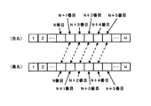
- FIG. 6 is a diagram for explaining pattern matching using a one-dimensional data string obtained from the measurement result by the sensor 10 executed by the car position calculation unit 14 in the elevator position detection device according to the first embodiment. be.
- FIG. 6 first shows an example of data handled by the car position calculation unit 14.
- the data handled by the car position calculation unit 14 shown in FIG. 6 can be obtained by arranging the electric resistance values as the measurement results by the sensor 10 in order corresponding to a plurality of predetermined positions along the cable 7. It is a one-dimensional data string.
- FIG. 6 is a diagram related to FIG. 3 described above.
- the positions of the sensor 10 when the car 4 is in the first position and the second position are indicated by white circles and black circles.
- FIG. 6 is an image in which the data of the electric resistance value, which is the measurement result by each sensor 10, is contained in the square frame.
- the sensors 10 are provided at a plurality of predetermined locations along the cable 7 for the electric resistance value which is the measurement result by the sensor 10 when the car 4 is in the first position. It is a one-dimensional data string obtained by arranging them in order according to their positions.
- the positions of the Nth to N + 5th sensors 10 are shown by using white circles, especially when they are in the first position.
- the lower figure of FIG. 6 shows the electric resistance value which is the measurement result by the sensor 10 when the car 4 is in the second position, and the positions where the sensors 10 are provided at a plurality of predetermined positions along the cable 7. It is a one-dimensional data string obtained by arranging them in order corresponding to.
- the positions of the Nth to N + 5th sensors 10 are shown by using black circles, especially when they are in the second position.
- the electrical resistance value which is the measurement result by the sensor 10 (sensors 10 from the first to the N-1) provided on the cable 7 on the hoistway device 6 side leading to the curved portion, shown in the upper and lower views of FIG. , Will show a relatively small value.
- the electric resistance value which is the measurement result by the sensor 10 (sensor 10 from N + 6th to Mth) provided on the cable 7 on the side of the car 4 leading to the curved portion, also shows a relatively small value. become.
- the reason why the electric resistance value, which is the measurement result by these sensors 10, shows a small value is as follows.
- the shape of the cable 7 at the location corresponding to the position where the sensor 10 is provided is substantially linear, that is, in the cable 7 at the location corresponding to the position where the sensor 10 is provided. Since the bending curvature is small and the bending deformation is received, it can be seen that the electric resistance value, which is the measurement result by these sensors 10, shows a small value.
- the electric resistance value which is the measurement result by the sensor 10 (the Nth to N + 5th sensors 10) corresponding to the curved portion, shows a relatively large value due to the bending deformation of the cable 7.
- the electric resistance value which is the measurement result by the N + 1th sensor 10 shown in the lower figure (black circle) of FIG. 5 and N + 2 shown in the upper figure (white circle) of FIG. 5 are used by using the broken line arrow. It shows that the electrical resistance values, which are the measurement results of the second sensor 10, are in a corresponding relationship. More precisely, the electric resistance value of the N + 1th sensor 10 shown in the lower figure (black circle) of FIG. 5 and the electric resistance value which is the measurement result by the N + 2nd sensor 10 shown in the upper figure (white circle) of FIG. 5 are It shows that the values are almost the same. This is related to the content described above, as it can be seen that the position of the N + 1th sensor 10 in the black circle and the position of the N + 2nd sensor 10 in the white circle are close to each other in the right figure in FIG. It is a thing.
- FIG. 6 is: That is, the position of the black circle N + 2nd sensor 10 and the position of the white circle N + 3rd sensor 10 shown in the right figure of FIG. 3 are the position of the black circle N + 3rd sensor 10 and the position of the white circle N + 4th sensor 10.
- FIG. 6 shows that the position of the black circle N + 4th sensor 10 and the position of the white circle N + 5th sensor 10 are closer to each other.
- the electrical resistance value which is the measurement result by the sensor 10 when the car 4 is in the first position, is set at a plurality of predetermined locations along the cable 7. It shows a one-dimensional data string obtained by arranging in order corresponding to the position where is provided.
- the database 13 already described stores this one-dimensional data string and the first position as a predetermined position as the measurement result by the sensor 10 when the car 4 is in the first position. It shall be.
- the detection algorithm of the car position calculation unit 14 uses a pattern matching method. Therefore, the procedure for the operation of the car position calculation unit 14 will be described below.
- FIG. 6 using the broken line arrows, for example, the electric resistance value which is the measurement result by the N + 1th sensor 10 shown in the lower figure (black circle) of FIG. 5 and the N + second value shown in the upper figure (white circle) of FIG. It was shown that the electrical resistance values, which are the measurement results by the sensor 10, have a corresponding relationship. As shown in FIG. 6, all the correspondences indicated by the broken line arrows indicate the pattern matching result in which the best similarity is obtained here. In other words, FIG. 6 is obtained by shifting the one-dimensional data string (shown in the lower figure of FIG. 6) obtained from the measurement result by the sensor 10 corresponding to the position of the car 4 at the present time by one by a square frame.
- the electrical resistance which is the measurement result by the N + 1th sensor 10 shown in the lower figure (black circle) of FIG. It is shown that the value and the electric resistance value which is the measurement result by the N + second sensor 10 shown in the upper figure (white circle) of FIG. 6 are substantially the same value.
- the position spacing of the sensors 10 on the cable 7 is preferably about 20 mm to 500 mm, and further, it is not always necessary to be evenly spaced, but it is evenly spaced from the viewpoint of convenience. Is preferable.
- shifting by one in a square frame means shifting one of the positional intervals of the sensors 10 on the cable 7 as physical distance information.
- the position spacing of the sensors 10 on the cable 7 is, for example, 50 mm.
- the position of the curved portion of the cable 7 at the present time is traced back by 50 mm with respect to the position of the curved portion of the cable 7 in the template stored in the database 13.
- the amount of vertical displacement of the car 4 can be obtained as a value that is half of the amount of movement of the position of the curved portion, as in the reference information described later, and thus the following can be understood.
- the position of the car 4 at the present time is raised by 25 mm, which is half of the 50 mm of the retroactive portion at the position of the curved portion in the cable 7. ..
- the data as the template stored in the database 13 is the one-dimensional data string shown in the upper figure of FIG. 6 and the first position as the car position at that time. Information. Then, assuming that the position when the car is in the second position is the reference position and the first position is, for example, the position where the car 4 is landing on the lowest floor, the position of the car 4 at the present time is It can be seen that it is located 25 mm above the bottom floor.
- the amount of movement of the position of the curved portion is known, it can be seen that the amount of vertical displacement of the car 4 at that time is obtained as a value half of the amount of movement of the position of the curved portion.
- the position detection device for the elevator has one end fixed to the device provided in the hoistway 31 and the other end fixed to the car 4 that moves up and down in the hoistway, and is suspended in a U shape.
- the belt-shaped cable 7 having a curved portion formed at the lower end position in the lowered state and the cable 7 provided at least at the curved portion of the cable covering portion of the cable 7 are provided.
- the sensor 10 is capable of measuring the change in physical quantity due to bending deformation along the line, and the sensor 10 is provided at a plurality of locations along the cable 7 at the curved portion when the car 4 is located at a predetermined car position.
- the curved portion of the cable 7 at the present time is compared with the measurement result by the sensor 10 when the car 4 is at the current car position. It is characterized by including a car position calculation unit 14 that estimates the position and calculates the position of the car 4 at the present time, which is determined according to the position of the curved portion in the cable 7 at the present time. be.
- the car position calculation unit 14 in the elevator position detection device corresponds the measurement result by the sensor 10 to the position where the sensor 10 is provided on the cable 7. It is treated as a one-dimensional data string obtained by arranging them in order, and the one-dimensional data string obtained from the measurement result by the sensor 10 measured in advance when the car 4 is in a predetermined car position.
- the database 13 stored as a template
- the position of the curved part in the cable at the present time is estimated based on the pattern matching result in which the best similarity is obtained, and the position of the curved part in the cable 7 at the present time is estimated corresponding to the position of the curved part in the cable 7 at the present time. It is characterized by calculating the position of the car 4 at the present time, which is determined.
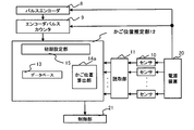
- FIG. 7 is a diagram for explaining an outline of the configuration of the elevator position detection device according to the second embodiment.
- the elevator position detection device according to the second embodiment replaces the car position calculation unit 14 in the elevator position detection device according to the first embodiment with a car position calculation unit 14a having a modified configuration.
- the car position calculation unit 14a in the elevator position detection device corresponds the measurement result by the sensor 10 to the position where the sensor is provided on the cable 7. It is treated as a one-dimensional data string obtained by arranging them in order, and the one-dimensional data string obtained from the measurement result by the sensor 10 measured in advance when the car 4 is in a predetermined car position.
- the sensor 10 corresponding to the one-dimensional data string obtained by referring to the database stored as a template and interpolating based on the one-dimensional data string as a template stored in the database 13 and the position of the car 4 at the present time.
- the position of the curved part in the cable 7 was estimated based on the pattern matching result obtained by performing pattern matching with the one-dimensional data string obtained from the measurement result obtained by the above, and the estimated current cable 7 It is characterized in that the position of the car 4 at the present time, which is determined according to the position of the curved portion in the above, is calculated.
- the accuracy of the position of the car 4 at the present time which is the calculation result of the car position calculation unit 14, depends on the measurement result by the sensor 10 measured in advance when the car 4 is on the terminal floor or near the terminal floor. It can be seen that there is an effect on. That is, in the first embodiment, the influence of the discretized data (electrical resistance value which is the measurement result by the sensor 10) shown by the black circle in FIG. 5 is the calculation result of the car position calculation unit 14 at the present time. There was a problem that it appeared in the accuracy of the position.
- the car position calculation unit 14a in the elevator position detection device has the accuracy of the position of the car 4 at the present time, which is the calculation result of the car position calculation unit 14, which is a problem in the first embodiment. It has been improved to improve.
- the car 4 is measured in advance when it is at or near the end of the hoistway 31.
- the primary obtained by referring to the database 13 in which the one-dimensional data string obtained from the measurement result by the sensor 10 is stored as a template and interpolating based on the one-dimensional data string of the template stored in the database 13.
- the point is to perform pattern matching between the original data string and the one-dimensional data string obtained from the measurement result by the sensor 10 corresponding to the current position of the car 4.
- the difference from the first embodiment is that the one-dimensional data string, which is one of the objects to be pattern-matched, is interpolated based on the one-dimensional data string of the template stored in the database 13. It is a point to make it a one-dimensional data string obtained by It can be said that the one-dimensional data string, which is different from the first embodiment, is obtained by using the points on the curve shown in FIG. 5 if it is explained in an easy-to-understand manner.
- the car position calculation unit 14a in the elevator position detection device according to the second embodiment shows the points indicated by the black circles in FIG. 5 as described above, instead of using the discretized data.
- the data interpolated for each of the two adjacent points is used.
- the curve obtained from the electric resistance value which is the measurement result by the sensor 10 in FIG. 5 is obtained corresponding to the shape of the curved portion of the cable 7.
- the fact that the curve obtained from the electric resistance value corresponds to the shape of the curved portion of the cable 7 means that the curve obtained from the electric resistance value and the shape of the curved portion of the cable 7 have a similar shape. I explained that it does not necessarily mean that.
- the horizontal axis of FIG. 5 corresponds to the position where the sensor 10 is provided at a plurality of predetermined positions along the cable 7, and the unit of the horizontal axis may be dimensionless. explained.
- the length of the curve obtained by interpolating the two adjacent points indicated by the black circles is the physical distance information of the position of the sensor 10 on the cable 7. It solves this problem by assuming that it corresponds to the interval.
- the current car 4 which is the calculation result of the car position calculation unit 14 which is a problem in the first embodiment. This has the effect that the accuracy of the position can be further improved as compared with the first embodiment.
- the interpolation method not only the interpolation using the curve shown in FIG. 5, but also the data obtained by linearly interpolating each of the two adjacent points indicated by the black circles may be used.
- the length of the straight line that interpolates each of the two adjacent points indicated by the black circles in FIG. 5 is the physical distance information
- the position interval of the sensor 10 on the cable 7 is the physical distance information. It is based on the assumption that it corresponds to.
- the elevator position detecting device uses the interpolation method using the linearly interpolated data
- the elevator position detecting device interpolates as compared with the interpolation method using the curve-interpolated data. It has the effect of making calculations easy.
- FIG. 8 is a diagram for explaining the outline of the configuration of the elevator position detecting device according to the third embodiment.
- the elevator position detection device according to the third embodiment replaces the car position calculation unit 14 in the elevator position detection device according to the first embodiment with the car position calculation unit 14b having a modified configuration.
- the car position calculation unit 14b in the position detection device of the elevator measures the measurement result by the sensor 10 when the car 4 is at the current car position at the position where the sensor 10 is provided on the cable 7. It is treated as a one-dimensional data string obtained by arranging them in order corresponding to each of the above, and was obtained from the measurement result by the sensor 10 measured in advance when the car 4 is in a predetermined car position.
- the database 13 that stores the information related to the position of the curved portion in the cable 7, and when the information related to the position of the curved portion stored in the database 13 and the car 4 at the current car position are present.
- the position of the curved portion on the cable 7 at the present time is estimated using the one-dimensional data string obtained from the measurement result by the sensor 10, and is determined corresponding to the estimated position of the curved portion on the cable 7 at the present time. It is characterized in that the position of the car 4 is calculated.
- the database 13 stores information related to the position of the curved portion in the cable 7. There is a certain point.
- the database 13 contains the one-dimensional data obtained from the measurement result by the sensor 10 measured in advance when the car 4 is on the terminal floor or near the terminal floor. He said that he remembered the columns as a template.
- the difference between the first embodiment and the second embodiment in the third embodiment is that the database 13 stores information related to the position of the curved portion in the cable 7. ..
- the car position calculation unit 14b in the position detection device of the elevator estimates the position of the curved portion in the cable 7 at the present time by using the database 13.
- the purpose is that the calculation load in the above can be reduced as compared with the first embodiment and the second embodiment.
- the information related to the position of the curved portion in the cable 7 is defined as a representative value obtained from the measurement result by the sensor 10 measured in advance when the car 4 is on the terminal floor or near the terminal floor. ..
- This representative value is literally a typical value, and a value indicating the characteristic is determined from the measurement result by the sensor 10 measured in advance when the car 4 is on the terminal floor or near the terminal floor. It is obtained by doing.
- the representative value for example, an extreme value or a moving average result can be considered.
- the feature of the information related to the position of the curved portion in the cable 7 is that it is point information.
- the data as a template stored in the database 13 is measured in advance when the car 4 is at or near the end of the hoistway 31.
- the data had the structure of a one-dimensional data string obtained from the measurement results of the sensor 10.
- the extreme value is used as the information related to the position of the curved portion in the cable 7, in the one-dimensional data string obtained from the measurement result by the sensor 10 when the position of the car 4 is at the present time
- the position of the curved portion in the cable 7 at the present time is estimated depending on the number of the sensor 10 that substantially matches the extreme value.
- the position of the car 4 at the present time is calculated and calculated by using the estimation result about the position of the curved portion in the cable 7 at the present time.
- the position of the curved portion in the cable 7 at the present time is estimated by two one-dimensional operations.
- a pattern matching operation is performed using a data string.
- the position of the curved portion in the cable 7 at the present time is estimated by using the point information and the one-dimensional data string. , The calculation for finding the correspondence with the information related to the position of the curved portion in the cable 7 is performed.
- the calculation load for estimating the position of the curved portion in the cable 7 at the present time using the database 13 is the same as that of the first embodiment and the embodiment. It is clear that the effect of mitigation can be achieved as compared with Form 2.
- the following configuration is further proposed as an elevator control system using the elevator position detection device according to any one of the first to third embodiments described above. It is a thing.
- the configuration of the elevator control system according to the first embodiment of the present disclosure as described above with reference to FIG. 2, the configuration of the elevator position detection device according to the first embodiment of the present disclosure , The control unit 21 is added.
- the elevator control system includes the elevator position detection device according to the present disclosure and the control unit 21 that controls the ascending / descending motion of the car, and the control unit 21 is calculated by the car position calculation unit 14 at present. It is characterized in that the ascending / descending motion of the car 4 is controlled by using the position of the car 4. With this configuration, it is possible to control the ascending / descending motion of the car 4 by using the current position of the car 4 calculated by the car position calculation unit instead of the pulse encoder 8. This has the effect of backing up the position detection of the pulse encoder.
- the control unit 21 further raises and lowers the car 4, and the latest car stored based on the output information of the pulse encoder 8 for detecting the rotation angle of the motor.
- the position information is used to control the ascending / descending motion of the car 4 in a normal state, and when the control unit 21 starts the ascending / descending motion after the latest car position information cannot be specified, the present disclosure It may be characterized in that the current position of the car 4 calculated by the car position calculation of the elevator position detection device in the above is used as information instead of the latest car position information.
- the car position is the calculation result of the car position calculation unit in the elevator position detection device.
- the information can be used by the control unit in the elevator control system as an alternative to the latest car location information. Therefore, even if the elevator stops in the vicinity of the terminal floor due to a power outage or the power supply is cut off by the power supply device and the car position information is lost, the elevator can be swiftly moved up and down to start the subsequent ascending / descending motion. It is possible to determine in which direction the car 4 should be driven or whether the car can be driven. As a result, it is possible to realize a safe ascending / descending motion of the car at the start of the ascending / descending motion.
Landscapes
- Indicating And Signalling Devices For Elevators (AREA)
- Lift-Guide Devices, And Elevator Ropes And Cables (AREA)
Priority Applications (3)
| Application Number | Priority Date | Filing Date | Title |
|---|---|---|---|
| JP2022510313A JP7226647B2 (ja) | 2020-03-27 | 2020-03-27 | エレベーターの位置検出装置とそれを用いたエレベーターの制御システム |
| CN202080097386.6A CN115279680B (zh) | 2020-03-27 | 2020-03-27 | 电梯位置检测装置和使用了该装置的电梯控制系统 |
| PCT/JP2020/013943 WO2021192209A1 (ja) | 2020-03-27 | 2020-03-27 | エレベーターの位置検出装置とそれを用いたエレベーターの制御システム |
Applications Claiming Priority (1)
| Application Number | Priority Date | Filing Date | Title |
|---|---|---|---|
| PCT/JP2020/013943 WO2021192209A1 (ja) | 2020-03-27 | 2020-03-27 | エレベーターの位置検出装置とそれを用いたエレベーターの制御システム |
Publications (1)
| Publication Number | Publication Date |
|---|---|
| WO2021192209A1 true WO2021192209A1 (ja) | 2021-09-30 |
Family
ID=77889944
Family Applications (1)
| Application Number | Title | Priority Date | Filing Date |
|---|---|---|---|
| PCT/JP2020/013943 Ceased WO2021192209A1 (ja) | 2020-03-27 | 2020-03-27 | エレベーターの位置検出装置とそれを用いたエレベーターの制御システム |
Country Status (3)
| Country | Link |
|---|---|
| JP (1) | JP7226647B2 (https=) |
| CN (1) | CN115279680B (https=) |
| WO (1) | WO2021192209A1 (https=) |
Citations (4)
| Publication number | Priority date | Publication date | Assignee | Title |
|---|---|---|---|---|
| JPS5115277Y1 (https=) * | 1970-09-30 | 1976-04-22 | ||
| JPH05262467A (ja) * | 1992-03-19 | 1993-10-12 | Hitachi Ltd | エレベータの位置検出装置 |
| JP2006036430A (ja) * | 2004-07-26 | 2006-02-09 | Mitsubishi Electric Corp | エレベータ装置 |
| CN110054046A (zh) * | 2019-05-17 | 2019-07-26 | 日立楼宇技术(广州)有限公司 | 基于补偿链的轿厢位置确定方法、装置、系统及电梯设备 |
Family Cites Families (9)
| Publication number | Priority date | Publication date | Assignee | Title |
|---|---|---|---|---|
| JP2004010207A (ja) * | 2002-06-04 | 2004-01-15 | Mitsubishi Electric Corp | エレベータのカゴ位置検出装置 |
| JP4940895B2 (ja) * | 2006-10-31 | 2012-05-30 | 株式会社日立製作所 | エレベーター |
| JP2012224422A (ja) * | 2011-04-18 | 2012-11-15 | Hitachi Ltd | エレベータの位置検出装置および方法 |
| JP5932577B2 (ja) * | 2012-09-06 | 2016-06-08 | 株式会社日立製作所 | エレベータの安全システム |
| WO2014136200A1 (ja) * | 2013-03-05 | 2014-09-12 | 三菱電機株式会社 | エレベータ装置及びそのかご位置検出方法 |
| WO2016157535A1 (ja) * | 2015-04-03 | 2016-10-06 | 三菱電機株式会社 | エレベータ装置 |
| WO2018016033A1 (ja) * | 2016-07-20 | 2018-01-25 | 三菱電機株式会社 | エレベータの制御装置および制御方法 |
| JP6804430B2 (ja) * | 2017-11-30 | 2020-12-23 | 株式会社日立製作所 | エレベーター用制御装置 |
| EP3599200B1 (en) * | 2018-07-23 | 2022-06-01 | KONE Corporation | Elevator |
-
2020
- 2020-03-27 CN CN202080097386.6A patent/CN115279680B/zh active Active
- 2020-03-27 WO PCT/JP2020/013943 patent/WO2021192209A1/ja not_active Ceased
- 2020-03-27 JP JP2022510313A patent/JP7226647B2/ja active Active
Patent Citations (4)
| Publication number | Priority date | Publication date | Assignee | Title |
|---|---|---|---|---|
| JPS5115277Y1 (https=) * | 1970-09-30 | 1976-04-22 | ||
| JPH05262467A (ja) * | 1992-03-19 | 1993-10-12 | Hitachi Ltd | エレベータの位置検出装置 |
| JP2006036430A (ja) * | 2004-07-26 | 2006-02-09 | Mitsubishi Electric Corp | エレベータ装置 |
| CN110054046A (zh) * | 2019-05-17 | 2019-07-26 | 日立楼宇技术(广州)有限公司 | 基于补偿链的轿厢位置确定方法、装置、系统及电梯设备 |
Also Published As
| Publication number | Publication date |
|---|---|
| CN115279680B (zh) | 2023-11-28 |
| JP7226647B2 (ja) | 2023-02-21 |
| JPWO2021192209A1 (https=) | 2021-09-30 |
| CN115279680A (zh) | 2022-11-01 |
Similar Documents
| Publication | Publication Date | Title |
|---|---|---|
| US9926170B2 (en) | Movement-monitoring system of an elevator installation | |
| EP2867150B1 (en) | Position and load measurement system for an elevator | |
| CN104276474B (zh) | 电梯的安全系统 | |
| JP4588773B2 (ja) | エレベータの異常検出装置 | |
| JP4468224B2 (ja) | エレベータの位置検出システム及び方法 | |
| KR20180031032A (ko) | 엘리베이터 장치 | |
| JPWO2014115402A1 (ja) | エレベータ装置 | |
| JP7727018B2 (ja) | エレベーターの制御システム | |
| JP2009215057A (ja) | エレベータの強制減速制御システム | |
| US20240034594A1 (en) | Elevator device | |
| CN109850705B (zh) | 电梯用控制装置 | |
| EP4313829B1 (en) | Method and system for estimating rope slip in an elevator system | |
| WO2021192209A1 (ja) | エレベーターの位置検出装置とそれを用いたエレベーターの制御システム | |
| CN1033694C (zh) | 电梯的终端楼层减速装置 | |
| JP3806287B2 (ja) | エレベータ装置 | |
| JP6680179B2 (ja) | エレベータ装置 | |
| CN114524341A (zh) | 电梯的检测方法、装置、电梯及计算机可读存储介质 | |
| JP6306135B1 (ja) | エレベータ制御装置 | |
| WO2018016033A1 (ja) | エレベータの制御装置および制御方法 | |
| WO2011089691A1 (ja) | エレベーター装置 | |
| HK40076310A (en) | Position detection device for elevator and elevator control system using same | |
| JP7725363B2 (ja) | エレベータ乗り心地評価システム及びその方法 | |
| HK40076310B (zh) | 电梯位置检测装置和使用了该装置的电梯控制系统 | |
| KR102333643B1 (ko) | 이상 검출 장치 | |
| CN109476450B (zh) | 电梯的控制装置 |
Legal Events
| Date | Code | Title | Description |
|---|---|---|---|
| 121 | Ep: the epo has been informed by wipo that ep was designated in this application |
Ref document number: 20927512 Country of ref document: EP Kind code of ref document: A1 |
|
| ENP | Entry into the national phase |
Ref document number: 2022510313 Country of ref document: JP Kind code of ref document: A |
|
| NENP | Non-entry into the national phase |
Ref country code: DE |
|
| 122 | Ep: pct application non-entry in european phase |
Ref document number: 20927512 Country of ref document: EP Kind code of ref document: A1 |