WO2021192044A1 - 作業システム - Google Patents
作業システム Download PDFInfo
- Publication number
- WO2021192044A1 WO2021192044A1 PCT/JP2020/013047 JP2020013047W WO2021192044A1 WO 2021192044 A1 WO2021192044 A1 WO 2021192044A1 JP 2020013047 W JP2020013047 W JP 2020013047W WO 2021192044 A1 WO2021192044 A1 WO 2021192044A1
- Authority
- WO
- WIPO (PCT)
- Prior art keywords
- work
- power
- power transmission
- machine
- work system
- Prior art date
- Legal status (The legal status is an assumption and is not a legal conclusion. Google has not performed a legal analysis and makes no representation as to the accuracy of the status listed.)
- Ceased
Links
Images






Classifications
-
- H—ELECTRICITY
- H02—GENERATION; CONVERSION OR DISTRIBUTION OF ELECTRIC POWER
- H02J—ELECTRIC POWER NETWORKS; CIRCUIT ARRANGEMENTS OR SYSTEMS FOR SUPPLYING OR DISTRIBUTING ELECTRIC POWER; SYSTEMS FOR STORING ELECTRIC ENERGY
- H02J50/00—Circuit arrangements or systems for wireless supply or distribution of electric power
- H02J50/20—Circuit arrangements or systems for wireless supply or distribution of electric power using microwaves or radio frequency waves
-
- E—FIXED CONSTRUCTIONS
- E02—HYDRAULIC ENGINEERING; FOUNDATIONS; SOIL SHIFTING
- E02F—DREDGING; SOIL-SHIFTING
- E02F9/00—Component parts of dredgers or soil-shifting machines, not restricted to one of the kinds covered by groups E02F3/00 - E02F7/00
- E02F9/20—Drives; Control devices
- E02F9/2025—Particular purposes of control systems not otherwise provided for
- E02F9/2054—Fleet management
-
- A—HUMAN NECESSITIES
- A01—AGRICULTURE; FORESTRY; ANIMAL HUSBANDRY; HUNTING; TRAPPING; FISHING
- A01D—HARVESTING; MOWING
- A01D34/00—Mowers; Mowing apparatus of harvesters
- A01D34/006—Control or measuring arrangements
- A01D34/008—Control or measuring arrangements for automated or remotely controlled operation
-
- B—PERFORMING OPERATIONS; TRANSPORTING
- B60—VEHICLES IN GENERAL
- B60L—PROPULSION OF ELECTRICALLY-PROPELLED VEHICLES; SUPPLYING ELECTRIC POWER FOR AUXILIARY EQUIPMENT OF ELECTRICALLY-PROPELLED VEHICLES; ELECTRODYNAMIC BRAKE SYSTEMS FOR VEHICLES IN GENERAL; MAGNETIC SUSPENSION OR LEVITATION FOR VEHICLES; MONITORING OPERATING VARIABLES OF ELECTRICALLY-PROPELLED VEHICLES; ELECTRIC SAFETY DEVICES FOR ELECTRICALLY-PROPELLED VEHICLES
- B60L53/00—Methods of charging batteries, specially adapted for electric vehicles; Charging stations or on-board charging equipment therefor; Exchange of energy storage elements in electric vehicles
- B60L53/10—Methods of charging batteries, specially adapted for electric vehicles; Charging stations or on-board charging equipment therefor; Exchange of energy storage elements in electric vehicles characterised by the energy transfer between the charging station and the vehicle
- B60L53/12—Inductive energy transfer
- B60L53/126—Methods for pairing a vehicle and a charging station, e.g. establishing a one-to-one relation between a wireless power transmitter and a wireless power receiver
-
- B—PERFORMING OPERATIONS; TRANSPORTING
- B60—VEHICLES IN GENERAL
- B60L—PROPULSION OF ELECTRICALLY-PROPELLED VEHICLES; SUPPLYING ELECTRIC POWER FOR AUXILIARY EQUIPMENT OF ELECTRICALLY-PROPELLED VEHICLES; ELECTRODYNAMIC BRAKE SYSTEMS FOR VEHICLES IN GENERAL; MAGNETIC SUSPENSION OR LEVITATION FOR VEHICLES; MONITORING OPERATING VARIABLES OF ELECTRICALLY-PROPELLED VEHICLES; ELECTRIC SAFETY DEVICES FOR ELECTRICALLY-PROPELLED VEHICLES
- B60L53/00—Methods of charging batteries, specially adapted for electric vehicles; Charging stations or on-board charging equipment therefor; Exchange of energy storage elements in electric vehicles
- B60L53/60—Monitoring or controlling charging stations
- B60L53/65—Monitoring or controlling charging stations involving identification of vehicles or their battery types
-
- B—PERFORMING OPERATIONS; TRANSPORTING
- B60—VEHICLES IN GENERAL
- B60L—PROPULSION OF ELECTRICALLY-PROPELLED VEHICLES; SUPPLYING ELECTRIC POWER FOR AUXILIARY EQUIPMENT OF ELECTRICALLY-PROPELLED VEHICLES; ELECTRODYNAMIC BRAKE SYSTEMS FOR VEHICLES IN GENERAL; MAGNETIC SUSPENSION OR LEVITATION FOR VEHICLES; MONITORING OPERATING VARIABLES OF ELECTRICALLY-PROPELLED VEHICLES; ELECTRIC SAFETY DEVICES FOR ELECTRICALLY-PROPELLED VEHICLES
- B60L53/00—Methods of charging batteries, specially adapted for electric vehicles; Charging stations or on-board charging equipment therefor; Exchange of energy storage elements in electric vehicles
- B60L53/60—Monitoring or controlling charging stations
- B60L53/68—Off-site monitoring or control, e.g. remote control
-
- E—FIXED CONSTRUCTIONS
- E02—HYDRAULIC ENGINEERING; FOUNDATIONS; SOIL SHIFTING
- E02F—DREDGING; SOIL-SHIFTING
- E02F9/00—Component parts of dredgers or soil-shifting machines, not restricted to one of the kinds covered by groups E02F3/00 - E02F7/00
- E02F9/20—Drives; Control devices
- E02F9/2058—Electric or electro-mechanical or mechanical control devices of vehicle sub-units
- E02F9/2062—Control of propulsion units
- E02F9/207—Control of propulsion units of the type electric propulsion units, e.g. electric motors or generators
-
- H—ELECTRICITY
- H02—GENERATION; CONVERSION OR DISTRIBUTION OF ELECTRIC POWER
- H02J—ELECTRIC POWER NETWORKS; CIRCUIT ARRANGEMENTS OR SYSTEMS FOR SUPPLYING OR DISTRIBUTING ELECTRIC POWER; SYSTEMS FOR STORING ELECTRIC ENERGY
- H02J50/00—Circuit arrangements or systems for wireless supply or distribution of electric power
- H02J50/40—Circuit arrangements or systems for wireless supply or distribution of electric power using two or more transmitting or receiving devices
-
- H—ELECTRICITY
- H02—GENERATION; CONVERSION OR DISTRIBUTION OF ELECTRIC POWER
- H02J—ELECTRIC POWER NETWORKS; CIRCUIT ARRANGEMENTS OR SYSTEMS FOR SUPPLYING OR DISTRIBUTING ELECTRIC POWER; SYSTEMS FOR STORING ELECTRIC ENERGY
- H02J7/00—Circuit arrangements for charging or discharging batteries or for supplying loads from batteries
- H02J7/40—Circuit arrangements for charging or discharging batteries or for supplying loads from batteries characterised by the exchange of charge or discharge related data
- H02J7/42—Circuit arrangements for charging or discharging batteries or for supplying loads from batteries characterised by the exchange of charge or discharge related data with electronic devices having internal batteries, e.g. mobile phones
-
- A—HUMAN NECESSITIES
- A01—AGRICULTURE; FORESTRY; ANIMAL HUSBANDRY; HUNTING; TRAPPING; FISHING
- A01D—HARVESTING; MOWING
- A01D2101/00—Lawn-mowers
-
- B—PERFORMING OPERATIONS; TRANSPORTING
- B60—VEHICLES IN GENERAL
- B60L—PROPULSION OF ELECTRICALLY-PROPELLED VEHICLES; SUPPLYING ELECTRIC POWER FOR AUXILIARY EQUIPMENT OF ELECTRICALLY-PROPELLED VEHICLES; ELECTRODYNAMIC BRAKE SYSTEMS FOR VEHICLES IN GENERAL; MAGNETIC SUSPENSION OR LEVITATION FOR VEHICLES; MONITORING OPERATING VARIABLES OF ELECTRICALLY-PROPELLED VEHICLES; ELECTRIC SAFETY DEVICES FOR ELECTRICALLY-PROPELLED VEHICLES
- B60L2200/00—Type of vehicles
- B60L2200/40—Working vehicles
-
- H—ELECTRICITY
- H02—GENERATION; CONVERSION OR DISTRIBUTION OF ELECTRIC POWER
- H02J—ELECTRIC POWER NETWORKS; CIRCUIT ARRANGEMENTS OR SYSTEMS FOR SUPPLYING OR DISTRIBUTING ELECTRIC POWER; SYSTEMS FOR STORING ELECTRIC ENERGY
- H02J2105/00—Networks for supplying or distributing electric power characterised by their spatial reach or by the load
- H02J2105/30—Networks for supplying or distributing electric power characterised by their spatial reach or by the load the load networks being external to vehicles, i.e. exchanging power with vehicles
- H02J2105/33—Networks for supplying or distributing electric power characterised by their spatial reach or by the load the load networks being external to vehicles, i.e. exchanging power with vehicles exchanging power with road vehicles
- H02J2105/37—Networks for supplying or distributing electric power characterised by their spatial reach or by the load the load networks being external to vehicles, i.e. exchanging power with vehicles exchanging power with road vehicles exchanging power with electric vehicles [EV] or with hybrid electric vehicles [HEV]
-
- Y—GENERAL TAGGING OF NEW TECHNOLOGICAL DEVELOPMENTS; GENERAL TAGGING OF CROSS-SECTIONAL TECHNOLOGIES SPANNING OVER SEVERAL SECTIONS OF THE IPC; TECHNICAL SUBJECTS COVERED BY FORMER USPC CROSS-REFERENCE ART COLLECTIONS [XRACs] AND DIGESTS
- Y02—TECHNOLOGIES OR APPLICATIONS FOR MITIGATION OR ADAPTATION AGAINST CLIMATE CHANGE
- Y02T—CLIMATE CHANGE MITIGATION TECHNOLOGIES RELATED TO TRANSPORTATION
- Y02T10/00—Road transport of goods or passengers
- Y02T10/60—Other road transportation technologies with climate change mitigation effect
- Y02T10/70—Energy storage systems for electromobility, e.g. batteries
Definitions
- the present invention relates to a work system.
- Patent Document 1 discloses a non-contact power supply technology that irradiates a solar battery mounted on the roof of an electric vehicle with light and supplies power generated by the solar battery to a secondary battery included in the electric vehicle. There is.
- An object of the present invention is to provide a working system capable of supplying electric power to a working machine.
- a work system including a plurality of work machines having a work unit and a power supply device for supplying electric power to the plurality of work machines.
- the plurality of working machines include a plurality of types of working machines having different amounts of electric power required to drive the working unit.
- the power feeding device includes a first power transmission means for wirelessly transmitting electric power to the work areas of the plurality of work machines.
- Each of the plurality of working machines is provided with a working system including a power receiving means for receiving electric power wirelessly transmitted to the working area.
- the work system includes a work machine and a power supply device for supplying electric power to the work machine.
- the power feeding device includes a first power transmission means for wirelessly transmitting electric power to the work area of the work machine.
- the first power transmission means transmits a constant capacity per unit area of the work area.
- the work machine includes a power receiving means for receiving electric power transmitted wirelessly to the work area. A working system characterized by this is provided.
- the schematic diagram which shows the application example of a work system The schematic diagram which shows the structure of the work machine and the power receiving mode.
- the block diagram of the work system of FIG. A flowchart showing a processing example of the server.
- Explanatory drawing which shows an example of the power feeding device which provided with a movable unit. Operation explanatory view of the movable unit.
- the schematic diagram which shows the application example of the work system which concerns on another Embodiment of this invention.
- the block diagram of the work system of FIG. Explanatory drawing which shows the transmission mode of regenerative electric power.
- Explanatory drawing which shows the transmission mode of regenerative electric power A flowchart showing a processing example of the server. Layout diagram showing an example of a manned work area.
- FIG. 1 is a schematic view showing an application example of the work system 100.
- the work system 100 includes a work machine 1 and a power supply device 20 for supplying electric power to the work machine 1.
- the work machine 1 performs lawn mowing work in the work area (lawn) WA adjacent to the house.
- the working machine 1 of the present embodiment does not have a function of collecting the cut grass, and the cut grass is left on the work area WA to be used as fertilizer.
- the working machine 1 may have a function of collecting the cut grass, and may have, for example, a mechanism of sending the cut grass to a recovery bag.
- the power supply device 20 includes a plurality of power transmission units 22 and wirelessly transmits power to the work area WA.
- the power transmission section 20a schematically shows the range in which each power transmission unit 22 wirelessly transmits power.
- the working machine 1 of the present embodiment is an autonomous electric lawn mower and has a power receiving unit 8. When the remaining battery level of the work machine 1 is low, the work machine 1 moves to the power transmission section 20a and receives power from the power transmission unit 22.
- the power transmission section 20a can also be said to be the charging section of the work machine 1.
- the power transmission section 20a is set so that there is no overlap.
- the work area WA is provided with a plurality of markers 101 indicating the section.
- the marker 101 is, for example, a columnar member.
- the working machine 1 includes a photographing device 9, and recognizes the marker 101 from the photographed image. Then, based on the recognition result, the work machine 1 performs the lawn mowing work while traveling so as not to protrude from the work area WA.
- the section of the work area WA may be laid so as to surround the work area WA and may be performed by an area wire that emits a magnetic field, and the work machine 1 recognizes the area wire and performs running and lawn mowing work. You may.
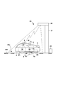
- FIG. 2 is a schematic view (elevation view of the power feeding device 20) showing the configuration of the working machine 1 and the power receiving mode of the working machine 1 from the power feeding device 20.
- the work machine 1 is a four-wheeled vehicle equipped with a traveling unit 3 having left and right front wheels 4B and left and right rear wheels 4A.
- the left and right rear wheels 4A are drive wheels, and move the work machine 1 on the work area.
- Each rear wheel 4 is provided with a drive mechanism using the motor 4a as a drive source, and the left and right rear wheels 4A are independently rotated and controlled. By independently controlling the rotation of the left and right rear wheels 4A, the traveling direction of the work machine 1 can be controlled.
- the left and right front wheels 4B are provided so as to be freely rotatable.
- the work machine 1 includes a work unit 5.
- the work unit 5 is a mechanism for mowing the lawn in the work area.
- the working unit 5 includes a rotary cutter 5a and a drive mechanism that rotates the rotary cutter 5a around a shaft 5b in a substantially vertical direction using a motor 5c as a drive source.
- the rotary cutter 5a is arranged below the vehicle body 2 in the central portion (between the front wheels 4B and the rear wheels 4A) in the front-rear direction of the work machine 1.
- the rotary cutter 5a of the present embodiment is provided with a blade so that the grass can be cut regardless of whether the rotation direction is forward rotation or reverse rotation.
- the working unit 5 may be provided with an elevating mechanism that changes the vertical position of the rotary cutter 5c.
- a photographing device 9 is provided at the front of the vehicle body 2 of the working machine 1.
- the photographing device 9 is a camera including an imaging sensor such as a CCD sensor and a CMOS sensor, and an optical system such as a lens.
- the photographing range 9a of the imaging device 9 is in front of the working machine 1.
- the photographing range 9a is not limited to this, and a 360-degree camera may be adopted as the photographing device 9.
- the work machine 1 is provided with a capacitor (battery) 6 as its power source.
- the capacitor 6 supplies electric power to the electric load included in the working machine 1, such as the motor 4a and the motor 5c, and the photographing device 9.
- a power receiving unit 8 for receiving electric power from the power feeding device 20 is provided on the upper portion of the vehicle body 2.
- the capacitor 6 can be charged with the electric power received by the power receiving unit 8.
- the control unit 10 controls each configuration of the work machine 1.
- the power supply device 20 includes a support 21 for each power transmission unit 22.
- the support 21 is a tower or a pillar erected outside the work area WA adjacent to the boundary of the work area WA, and supports the power transmission unit 22 at a position higher than the ground surface of the work area WA.
- the power transmission unit 22 radiates radio waves from a position higher than the work area WA, and wirelessly supplies power to the power reception unit 8.
- the power feeding device 20 also includes a control unit 23.
- the control unit 23 controls each power transmission unit 22. Electric power is supplied to the power feeding device 20 from, for example, an electric power system.
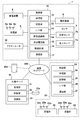
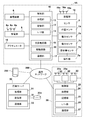
- FIG. 3 is a block diagram showing a circuit configuration of the work system 100.
- the control unit 23 of the power feeding device 20 includes a processing unit 24, a storage unit 25 such as RAM and ROM, and an interface unit (I / F unit) 26 that relays transmission and reception of signals between an external device and the processing unit 24.
- the processing unit 24 is a processor typified by a CPU, executes a program stored in the storage unit 25, and performs operations such as an operating period of each power transmission unit 22 based on a control instruction or the like received by the communication unit 27. Control.
- the power transmission unit 22 of the present embodiment is a circuit that performs radiant wireless power transmission, and includes, for example, a plurality of power transmission antennas 22a that radiate microwaves, a microwave transmitter, a phase shifter for each power transmission antenna, an amplifier, and the like. ..
- Each transmission direction and phase shift of the plurality of transmission antennas 22a are adjusted so that a constant capacity is transmitted per unit area in the transmission area 20a. Adjustments can be made before the system is operational.
- the communication unit 27 can wirelessly communicate with the management server 30 via the communication network 200.
- the management server 30 is a server that manages the power supply device 20 and the work machine 1.
- the management server 30 may instruct the start / end of the operation of the power supply device 20.
- the control unit 10 of the work machine 1 includes a processing unit 11, a storage unit 12 such as RAM and ROM, and an interface unit (I / F unit) 13 that relays transmission and reception of signals between an external device and the processing unit 11.
- the processing unit 11 is a processor typified by a CPU, executes a program stored in the storage unit 12, and based on the detection result of the sensor 7, the control instruction received by the communication unit 17, and the like, the actuator 18 and shooting.
- the actuator 18 includes a motor 4a and a motor 5c, and the processing unit 11 controls the drive of these motors via the drive circuit 16.
- the sensor 7 includes a position sensor 7a and a power sensor 7b.
- the position sensor 7a is a sensor for specifying the current position of the work machine 1, and examples thereof include a sensor that detects the amount of rotation of the left and right rear wheels 4, a GPS sensor, or both.
- the sensor that detects the amount of rotation of the left and right rear wheels 4 is, for example, a rotary encoder, which may directly detect the amount of rotation of the drive shaft of the rear wheels 4 or detect the amount of rotation of the output shaft of the motor 4a. It may be.
- the current position of the work machine 1 may be specified from the captured image by photographing the marker arranged in the work area WA with the image pickup device 9, or may be arranged in the work area. It may be specified from the information acquired by wireless communication from the beacon.
- the power sensor 7b includes, for example, a current sensor and a voltage sensor, and detects the amount of charge / discharge between the charge / discharge circuit 15 and the capacitor 6.
- the processing unit 11 monitors the remaining amount of the capacitor 6 based on the measurement result of the power sensor 7b. It is possible to measure the current and voltage supplied from the power receiving unit 8 to the capacitor 6 via the charging circuit 15 by the power sensor 7b. That is, the power sensor 7b functions as a sensor for measuring the amount of power received by the power receiving unit 8.
- the processing unit 11 can calculate the amount of power received by the power receiving unit 8 from the measurement result of the power sensor 7b during charging.
- the control unit 10 also includes an image recognition unit 14 that recognizes the content of the image captured by the photographing device 9.
- the image recognition unit 14 is, for example, an image processing processor, which analyzes the captured image and identifies the type of the object included in the captured image.
- the image recognition unit 14 may function as machine-learned artificial intelligence specialized in image recognition. Based on the recognition result of the image recognition unit 14, the processing unit 11 performs work machine 1 such as avoiding obstacles, turning back at the boundary of the work area WA, and controlling the rotation of the rotary cutter 5a by the density of the turf. Control the operation of.
- the control unit 10 includes a charge / discharge circuit 15 that charges or discharges the capacitor 6.
- the charging / discharging circuit 15 can charge the capacitor 6 with the electric power received by the power receiving unit 8. Further, the electric power stored in the capacitor 6 is discharged and supplied to the drive circuit 16 and the like.
- the control unit 10 also includes a communication unit 17.
- the communication unit 17 can wirelessly communicate with the management server 30 via the communication network 200.
- the management server 30 is a server that manages the work machine 1, and can manage information of a plurality of work machines 1, for example.
- the management server 30 can wirelessly communicate with a mobile terminal 202 such as a smartphone via the communication network 200.
- the mobile terminal 202 is, for example, a terminal of an administrator of the system 100 or a worker of the work machine 1.
- the information of the work machine 1 and the power supply device 20 can be received from the management server 30.
- the administrator can monitor the work machine 1 and the power supply device 20 even at a place away from the work machine 1 and the power supply device 20.
- the operation input to the mobile terminal 202 may be transmitted as a control command to the work machine 1 and the power supply device 20 via the management server 30.
- the operator can remotely control the power supply device 20 by the mobile terminal 202.
- the worker can also remotely control the work machine 1 by the mobile terminal 202.
- the worker can remotely control the work machine 1 from the vicinity of the work area WA to perform the lawn mowing work.
- the mobile terminal 202 or a dedicated radio controller may directly perform wireless communication with the control unit 10 to remotely control the work equipment 1.
- the power receiving unit 8 includes a power receiving antenna 8a that receives radio waves from the power transmitting unit 22, a conversion circuit that converts the radio waves received by the power receiving antenna 8a into electric power, and the like.
- One or more sets of the power receiving antenna 8a and the conversion circuit are provided depending on the power required by the working machine 1. The more pairs of the power receiving antenna 8a and the conversion circuit, the more power can be received, and the power receiving capacity can be adjusted according to the number of pairs. Alternatively, the power receiving capacity can be adjusted by setting the power receiving area of the power receiving antenna 8a according to the power required by the work machine 1.
- the power transmission unit 22 transmits a constant capacity per unit area in the power transmission area 20a. By adjusting the power receiving capacity of the work machine 1, the power required for the work machine 1 can be simply set.
- the management server 30 includes a processing unit 31, a storage unit 32 such as RAM, ROM, and a hard disk, and a communication unit 33.
- the processing unit 31 is a processor typified by a CPU, and executes a program stored in the storage unit 32.
- the communication unit 33 can communicate with the work machine 1, the power supply device 20, and the mobile terminal 202 via the communication network 200.
- a database 32a that stores various management information of the work system 100 is constructed.
- the work machine 1 starts the lawn mowing work in the work area WA, for example, by receiving the work start instruction from the management server 30.
- the work machine 1 operates autonomously and runs on its own in the work area WA to mow the lawn.
- the control contents executed by the control unit 10 of the work machine 1 include free control for arbitrarily performing the lawn mowing work in the work area WA and schedule control for performing the lawn mowing work in the work area WA according to a predetermined work schedule. Can be done.
- the free control is a control in which the lawn mowing work is performed while the work machine 1 is moving straight, and the traveling direction is sequentially switched at the boundary of the work area WA. The direction of travel may be randomly determined or may be determined according to certain rules.
- Schedule control is a control in which the lawn mowing work is performed while basically moving the work machine 1 according to a predetermined route.
- the coordinate information and the work plan information of the work area WA are stored in advance in the storage unit 12.
- the control unit 10 confirms the current position of the work machine 1 based on the detection result of the position sensor 7a, moves the predetermined path, and performs the lawn mowing work.
- the control unit 10 moves the work machine 1 to the power transmission area 20a and receives power from the power receiving device 20.
- the management server 30 may transmit the position information of the power transmission area 20a to the control unit 10, and the control unit 10 may move the work machine 1 to the power transmission area 20a based on the received position information.
- the power feeding device 20 may constantly transmit electric power to the power transmission area 20a during the work of the work machine 1, or leaves the power supply device 20 while the work machine 1 is in the power transmission area 20a or after approaching the power transmission area 20a. In the meantime, power may be transmitted.
- the management server 30 may receive the current position information of the work machine 1 from the control unit 10 of the work machine 1 and control the start and end of power transmission of the power supply device 20. For example, the management server 30 instructs the control unit 23 of the power feeding device 20 to start power transmission when the work machine 1 approaches a certain distance to the power transmission area 20a, and the work machine 1 is constant from the power transmission area 20a. After moving out of the distance, the control unit 23 of the power feeding device 20 is instructed to end the power transmission.
- the work system 100 of the present embodiment it is possible to supply electric power to the work machine 1 during work, and work efficiency can be improved.
- FIG. 4 shows an example of processing executed by the processing unit 31 of the management server 30.
- the control unit 10 saves the measurement result by the power sensor 7b as the amount of power received and transmits it to the management server 30 together with the individual information of the work machine 1. ..
- the management server 30 acquires (receives) the power measurement result from the control unit 10 (S1).
- the management server 30 generates billing information indicating the billing amount based on the information acquired in S1.
- the charge amount is increased in proportion to the magnitude of the electric power amount, for example.
- the management server 30 updates the database 32a.
- the user information corresponding to the individual information of the work machine 1 received in S1 is updated with the billing information generated in S2.
- the billing information stored in the database 32a is then used when billing the user for the billing amount.
- the power feeding device 20 may have a mechanism capable of changing the power transmission direction of the power transmission unit 22.
- FIG. 5 shows an example thereof.
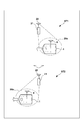
- the power feeding device 20 in the figure is provided with a movable portion 28 having an actuator such as a motor on the support 21, and the movable portion 28 rotates the power transmitting portion 22 around the shaft 28a as a rotation center.
- the control unit 23 changes the power transmission direction by driving the movable unit 28 and changing the direction of the power transmission unit 22.
- FIG. 6 shows a control example in which the power transmission direction of the power transmission unit 22 is changed.
- the illustrated states ST1 and ST2 exemplify the mode in which the working machine 1 is moving.
- the control unit 23 changes the direction of the power transmission unit 22 by the movable unit 28 according to the movement of the work machine 1, thereby controlling the power transmission direction of the power transmission unit 22.
- the power transmission area 20a is moving in accordance with the movement of the work machine 1. Controlling power transmission so that a certain amount of power is transmitted per unit area by changing the radio wave radiation conditions (phase shift and amplitude) for each power transmission antenna 22a as necessary according to the movement of the power transmission area 20a. Can be done.
- control unit 23 of the power supply device 20 recognizes the moving position of the work machine 1, for example, the control unit 10 of the work machine 1 always provides the current position information to the management server 30, and the management server 30 controls the power supply device 20.
- the current position information of the working machine 1 may be provided to the unit 23.
- the power transmission unit 22 By changing the direction of the power transmission unit 22 according to the movement of the work machine 1, more electric power can be supplied to the work machine 1 even if the power transmission area 20a is small. Further, when it is difficult for the work machine 1 to enter the power transmission area 20a due to the presence of an obstacle on the work area WA, the power can be more reliably supplied to the work machine 1 by moving in the power transmission area 20a. Further, the work efficiency can be improved by supplying electric power to the work machine 1 in a state where the work machine 1 continues the predetermined work.
- the lawn mower is illustrated as the work machine 1, but the work system 100 can also be applied to other types of work machines such as snowplows, cultivators, and construction machines. Further, a plurality of work machines or a plurality of types of work machines may be arranged in the work area WA.
- FIG. 7 shows an example in which the construction site is set as the work area WA.
- a large number of sets of the support 21 and the power transmission unit 22 are arranged along the boundary, and in the work area WA, a large number of power transmission sections 20a are set so as not to overlap each other over substantially the entire area. ing. Therefore, it is possible to supply electric power to the work machine at any place in the work area WA.
- the work machine 1A is an electric dump truck, and has a traveling unit 40 and a working unit (loading platform) 41. For example, earth and sand are loaded on the work unit 41, and the earth and sand are carried into the work area WA or are carried out from the work area WA.
- the work machine 1B is an electric excavator car, and includes a traveling unit 42 and a working unit (boom, arm, bucket) 43.
- the work unit 43 excavates the work area WA.
- the work machine 1C is an electric compaction machine and includes a work unit (striking unit) 44.
- the work area WA is leveled by hitting the work unit 44.
- the working machine 1C does not have a traveling portion.
- the work machines 1A to 1C of the present embodiment are work machines that are operated by an operator operating or operating. However, these working machines may be autonomous working machines such as the working machine 1 of the first embodiment or working machines operated by remote control.
- the working machines 1A to 1C have a power receiving unit 8 that receives power from the power transmitting unit 22, and also has a power transmitting unit 19 that transmits the regenerative power generated by the working machines 1A to 1C to the outside.
- a power storage device 50 is also installed in the work area WA.
- the power storage device 50 has a power receiving unit similar to the power receiving unit 8 and a capacitor (battery) for storing the received power, and charges the power storage device by receiving the power transmitted from each power transmission unit 19 of the working machines 1A to 1C. It is possible.
- FIG. 8 is a block diagram showing a circuit configuration of the work system 100 in this embodiment.
- the figure shows the circuit configuration of the working machine 1A among the working machines 1A to 1C. A configuration different from the working machine 1 of the first embodiment will be described.
- the actuator 18 includes a motor that drives the traveling unit 40 and a motor that drives the working unit 41 (a motor for tilting the loading platform).
- the drive circuit 16 drives the motor of the actuator 18, while supplying the regenerative power generated by the motor to the charge / discharge circuit 15 or the power transmission unit 19.
- the regenerative power is used to charge the capacitor 6 via the charge / discharge circuit 15.
- the regenerative power is supplied to the power transmission unit 19, and is transmitted from the power transmission unit 19 to the outside.
- the work machine 1A includes a power transmission unit 19.
- the power transmission unit 19 has the same configuration as the power transmission unit 22 of the power supply device 20, and is a circuit that performs radiant wireless power transmission.
- the power transmission unit 19 includes a plurality of power transmission antennas 19a, a microwave transmitter, a phase shifter for each power transmission antenna, an amplifier, and the like.
- the sensor 7 includes a power sensor 7c and an operation amount sensor 7d.
- the power sensor 7c is a sensor that measures the electric energy of the regenerated electric power supplied to the power transmission unit 19, and measures, for example, current and voltage.
- the operation amount sensor 7d is a sensor that detects the operation amount of the operator with respect to the operation unit 7e.
- the operation unit 7e includes operators (for example, accelerator pedal, brake pedal, steering handle) that instruct the acceleration, deceleration, and steering of the work unit 1A, and controls that instruct the operation of the work unit 41.
- the control unit 10 controls the drive of the actuator 18 based on the detection result of the operation amount sensor 7d, and operates the work machine 1A.
- the working machine 1A Since the working machine 1A is operated by an operator, the working machine 1A is not provided with a photographing device 9 or an image recognition unit 14 like the working machine 1. However, it may be configured to include these.
- the circuit configuration of the working machine 1B is the same as that of the working machine 1A.
- the actuator 18 of the work machine 1B includes a motor for driving the traveling unit 42 and a motor for driving the work unit 43.
- the circuit configuration of the working machine 1C is the same as that of the working machine 1A.
- the actuator 18 of the work machine 1A includes a motor for driving the work unit 44, but since the work machine 1C does not have a traveling unit, it does not have a motor for the traveling unit.
- the operation unit 7e includes, for example, an operator for instructing to drive and stop the work unit 44, but since the work machine 1C does not have a traveling unit, the operation unit 7e does not have an operator for the traveling unit.
- the power supply device 20, the management server 30, and the mobile terminal 202 are the same as those in the first embodiment.
- the work machines 1A to 1C are operated by the operator's operation, and the construction work is performed in the work area WA.
- the work area WA is set so that a large number of power transmission sections 20a do not overlap each other over substantially the entire area.
- power is basically supplied from the constant power supply device 20 to the work machines 1A to 1C, and work interruption due to a decrease in the remaining amount of the capacitor 6 can be avoided.
- the power supply device 20 may transmit electric power while the working machines 1A to 1C are in the power transmission area 20a, or after approaching and leaving the power transmission area 20a.
- the management server 30 receives the current position information of the work machine 1 from each control unit 10 of the work machines 1A to 1C, and starts and ends the power transmission of the power supply device 20. You may control it.
- the work system 100 of the present embodiment it is possible to supply electric power to the work machines 1A to 1C during work, and the work efficiency can be improved.
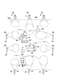
- FIG. 9 is an explanatory diagram showing an example thereof.
- the work machine 1A has a traveling unit 40, and when descending an inclined surface in the working area WA, the motor 18a, which is the drive source of the traveling unit 40, may generate regenerative power.
- the regenerative power generated by the motor 18a is transmitted to the outside from the power transmission unit 19.
- the surplus electric power in the working machine 1A can be distributed to the other working machine 1C.
- the power transmission direction of the power transmission unit 19 may be adjusted by the phase shift and amplitude of the radio wave to be controlled so that the power is efficiently transmitted to the other work machine 1C.
- the management server 30 may receive the current position information from the work machine 1C and transmit it to the control unit 10 of the work machine 1A to provide the current position information.
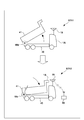
- FIG. 10 is an explanatory diagram showing another example of power transmission of regenerative electric power.
- the work machine 1A has a work unit 41, and the motor 18b, which is the drive source of the work unit 41, can generate regenerative power.
- the state ST11 indicates a state in which the working unit 41 is tilted from the initial position, and at this time, the motor 18b functions as a drive source. Therefore, it is in a state of consuming power.
- the state ST12 indicates a state in which the inclined working portion 41 is returned from the inclined position to the initial position. At this time, the motor 18b generates regenerative power as a generator.
- the regenerative power generated by the motor 18a is transmitted to the outside from the power transmission unit 19.
- the surplus electric power in the work machine 1A can be distributed to the power storage device 50.
- the power storage device 50 can be used as a power source for various electric products.
- the working machine 1A is taken as an example in FIGS. 9 and 10, the working machine 1B can also transmit the regenerative power of each motor of the traveling unit 42 and the working unit 43 to the outside from the power transmitting unit 19. Further, also in the work machine 1C, the regenerative power of the motor of the work unit 44 can be transmitted to the outside from the power transmission unit 19.
- the working machines 1A to 1C may be supplied with electric power from the power feeding device 20 while providing regenerative electric power to the surroundings. Therefore, the billing amount can be set by balancing the power consumption and the power supply.
- FIG. 11 shows an example of processing executed by the processing unit 31 of the management server 30 in this embodiment.
- the control unit 10 saves the measurement result by the power sensor 7b as the amount of power received, and manages the management server together with the individual information of the work machines 1A to 1C. Send to 30.
- the control unit 10 saves the measurement result by the power sensor 7c as the amount of power to be transmitted and sends it to the management server 30 together with the individual information of the working machines 1A to 1C.
- the server 30 acquires (receives) two types of power measurement results from the control unit 10 (S11).
- the management server 30 In S12, the management server 30 generates billing information indicating the billing amount based on the information acquired in S11. The charge amount is increased in proportion to the magnitude of the received power and decreased in proportion to the magnitude of the transmitted power, for example.
- the management server 30 updates the database 32a.
- the user information corresponding to the individual information of the work machines 1A to 1C received in S11 is updated with the billing information generated in S12.
- the billing information stored in the database 32a is then used when billing the user for the billing amount.
- the power transmission area 20a is set over substantially the entire work area WA without overlapping each other, but as shown in the first embodiment, power transmission is performed only to a predetermined area in the work area WA.
- the control unit 10 moves the working devices 1A to 1C to the power transmission area 20a and receives power.
- the power supply device 20 may have a configuration in which power is supplied from the power transmission unit 20, and as shown in the second embodiment, the power supply device 20 has a configuration in which the power transmission direction of the power transmission unit 22 can be changed, and the work machines 1A to 1C move.
- the direction of the power transmission unit 22 (position of the power transmission area 20a) may be changed according to the above.
- a manned work area may be provided adjacent to the work area WA.
- FIG. 12 is a layout diagram showing an example thereof.
- the power supply device 20 is not arranged around the manned work area WB, and is regarded as a work area where there is little radio wave for power transmission.
- Work machines 1A and 1B are arranged in the work area WA, and these are operated by, for example, remote control or autonomous operation. As a result, the work area WA can be made into an unmanned work area.
- a work system (100) of the above embodiment A work system (100) including a plurality of work machines (1,1A-1C) having a work unit (5,41,43,44) and a power supply device (20) for supplying electric power to the work machine.
- the plurality of working machines include a plurality of types of working machines having different amounts of electric power required to drive the working unit.
- the power feeding device comprises a first power transmission means (22) that wirelessly transmits power to the work area (WA) of the work machine.
- the work machine includes a power receiving means (8) that receives electric power that is wirelessly transmitted to the work area.
- electric power is wirelessly transmitted to the work area, and by providing the work machine with a power receiving means, the electric power required to drive the work unit without interrupting the work on the work area. It is possible to efficiently supply electric power to a plurality of types of work machines having different amounts, and to realize efficient work.
- a work system (100) of the above embodiment A work system (100) including a work machine (1,1A-1C) and a power supply device (20) for supplying electric power to the work machine.
- the power feeding device comprises a first power transmission means (22) that wirelessly transmits power to the work area (WA) of the work machine.
- the first power transmission means transmits a constant capacity per unit area of the work area.
- the work machine includes a power receiving means (8) that receives electric power that is wirelessly transmitted to the work area. According to this embodiment, it is possible to provide a working system capable of supplying electric power to a working machine. By transmitting a certain amount of power to the work area and adjusting the power receiving capacity of the power receiving side, it is possible to adjust the power required for the work according to the type of work machine having different required power.
- the work machine has a work unit (5,43,44) that works on the surface of the earth.
- the power feeding device is erected adjacent to the outside of the work area and includes a support (21) that supports the first power transmission means at a position higher than the work area.
- the first power transmission means performs radiant wireless power transmission. According to this embodiment, it is possible to supply power to the work machine without interrupting the work performed by the work machine on the ground surface, so that work efficiency can be improved.
- the power feeding device includes a plurality of the first power transmission means and control means (23) for controlling each first power transmission means.
- the control means controls each first power transmission means so that the transmission areas (20a) of the first power transmission means do not overlap. According to this embodiment, it is possible to reduce the bias of the electric power supplied to the work area and suppress the excessive power supply to the work machine.
- the power feeding device includes movable means (28) capable of changing the power transmission direction of the first power transmission means, and control means (23) for controlling the movable means.
- the control means controls the power transmission direction of the first power transmission means by the movable means in accordance with the movement of the work machine. According to this embodiment, as compared with the case where the power transmission direction is fixed, it is possible to suppress the occurrence of a state in which the power receiving means cannot receive power due to, for example, an obstacle.
- the working machine has a capacitor (6) that stores electric power received by the power receiving means. According to this embodiment, even in the case of fluctuations in the work load (required power) or temporary power reception failure, stable work can be performed by utilizing the stored power.
- the working machine is an autonomous working machine (1).
- the work area can be unmanned.
- the work machine includes a receiving means (17) for receiving a control instruction from the outside of the work area.
- the work machine can be remotely controlled, and the work area can be unmanned.
- a manned work area (WB) is provided adjacent to the work area (WA). According to this embodiment, a work area where electric power is transmitted and a manned work area where electric power is not transmitted can be separated.
- the working machine is Traveling means (40,42) using a motor as a drive source, A second power transmission means (19) for wirelessly transmitting the regenerative power of the motor is provided.
- the surplus regenerative power can be utilized by wirelessly transmitting the surplus regenerative power to the surroundings.
- the second power transmission means wirelessly transmits the regenerative power to a power storage device (50) provided in the work area.
- the surplus regenerative power can be utilized by wirelessly transmitting the surplus regenerative power to the surroundings.
- the second power transmission means wirelessly transmits the regenerative power to another work machine (1C) that works in the work area.
- the surplus regenerative power can be utilized by wirelessly transmitting the surplus regenerative power to the surroundings.
- the other working machine (1C) does not have a traveling means for running the other working machine.
- the required electric power can be allocated between the working machines by transmitting power from the working machine that can be regenerated by the traveling means to the working machine that does not have the traveling means and is difficult to regenerate.
- the working machine is a shovel car (1B) or a dump truck (1A).
- the load fluctuation difference in operation is large, and a large amount of regenerative power may be obtained.
- the working machine is a consolidation machine (1C). According to this embodiment, a large amount of regenerative power may be obtained during vibration.
- a measuring means (7b) for measuring the amount of electric power received by the power receiving means, and A billing information generating means (30) for generating billing information based on the measurement result of the measuring means is provided. According to this embodiment, by charging based on the amount of electric power provided for the work, it is possible to accurately charge the user who handles the work machine.
- the work system of the above embodiment The first measuring means (7b) for measuring the amount of electric power received by the power receiving means, and The second measuring means (7c) for measuring the amount of electric power transmitted by the second power transmitting means, and A billing information generating means (30) for generating billing information based on the measurement results of the first measuring means and the second measuring means is provided. According to this embodiment, by charging based on the amount of electric power provided for the work, it is possible to accurately charge the user who handles the work machine.
Landscapes
- Engineering & Computer Science (AREA)
- Power Engineering (AREA)
- Transportation (AREA)
- Mechanical Engineering (AREA)
- Computer Networks & Wireless Communication (AREA)
- Civil Engineering (AREA)
- Structural Engineering (AREA)
- General Engineering & Computer Science (AREA)
- Mining & Mineral Resources (AREA)
- Life Sciences & Earth Sciences (AREA)
- Environmental Sciences (AREA)
- Current-Collector Devices For Electrically Propelled Vehicles (AREA)
- Charge And Discharge Circuits For Batteries Or The Like (AREA)
- Electrical Discharge Machining, Electrochemical Machining, And Combined Machining (AREA)
Abstract
Description
作業部を有する複数の作業機と、前記複数の作業機に電力を供給する給電装置と、を備える作業システムであって、
前記複数の作業機は、前記作業部を駆動させるために必要な電力量が異なる複数種類の作業機を含み、
前記給電装置は、前記複数の作業機の作業エリアに対して電力を無線送電する第一の送電手段を備え、
前記複数の作業機は、それぞれ、前記作業エリアに対して無線送電される電力を受電する受電手段を備える
ことを特徴とする作業システムが提供される。
前記給電装置は、前記作業機の作業エリアに対して電力を無線送電する第一の送電手段を備え、
前記第一の送電手段は該作業エリアの単位面積当たり一定容量の送電を行い、
前記作業機は、前記作業エリアに対して無線送電される電力を受電する受電手段を備える、
ことを特徴とする作業システムが提供される。
<システムの概要>
図1は作業システム100の適用例を示す模式図である。作業システム100は、作業機1と、作業機1に電力を供給する給電装置20とを備える。作業機1は、家屋に隣接した作業エリア(芝地)WAの芝刈り作業を行う。本実施形態の作業機1は、刈り取った芝を回収する機能を有しておらず、刈り取った芝は作業エリアWA上に放置されて肥料とされる。なお、作業機1は刈り取った芝を回収する機能を有していてもよく、例えば、回収袋に刈り取った芝を送り出す機構を有していてもよい。
図2は作業機1の構成及び給電装置20からの作業機1の受電態様を示す模式図(給電装置20の立面図)である。
図3は、作業システム100の回路構成を示すブロック図である。給電装置20の制御部23は、処理部24と、RAM、ROM等の記憶部25と、外部デバイスと処理部24との信号の送受信を中継するインタフェース部(I/F部)26と、を含む。処理部24は、CPUに代表されるプロセッサであり、記憶部25に記憶されたプログラムを実行し、通信部27で受信した制御指示等に基づいて、各送電部22の稼働期間等の動作を制御する。
作業システム100の動作例について再び図1を参照して説明する。作業機1は例えば管理サーバ30からの作業開始指示を受信することにより、作業エリアWAにおける芝刈り作業を開始する。作業機1は、自律的に動作し、作業エリアWA内で自走して芝刈り作業を行う。
給電装置20及び作業機1をリースするサービス形態の場合、サービスを利用するユーザに対して、作業機1で消費された電力(つまり給電装置20から給電した電力)に比例したランニングコストを課金するビジネスを想定することができる。課金量を設定するため、管理サーバ30は作業機1の消費電力を監視し、リース先のユーザに関する課金情報を生成してもよい。図4は管理サーバ30の処理部31が実行する処理例を示している。作業機1が送電区域20aにおいて給電装置20から電力の供給を受けた場合、制御部10は受電力量として電力センサ7bによる計測結果を保存し、作業機1の個体情報と共に管理サーバ30へ送信する。
給電装置20は、送電部22の送電方向を変更可能な機構を有していてもよい。図5はその一例を示す。同図の給電装置20は、支持体21にモータ等のアクチュエータを有する可動部28が設けられており、可動部28は送電部22を軸28aを回動中心として回動させる。制御部23は可動部28を駆動して送電部22の向きを変更することでその送電方向を変更する。
第一実施形態では、作業機1として芝刈り機を例示したが、除雪機、耕運機、建機等、他の種類の作業機にも作業システム100を適用可能である。また、作業エリアWAには複数の作業機、或いは、複数種類の作業機が配置されていてもよい。
管理サーバ30は、制御部10から2種類の電力の計測結果を取得(受信)する(S11)。S12で、管理サーバ30はS11で取得した情報に基づき、課金量を示す課金情報を生成する。課金量は、例えば、受電力の大きさに比例して多くされ、送電力量の大きさに比例して少なくされる。S13で管理サーバ30はデータベース32aを更新する。ここでは、S11で受信した作業機1A~1Cの個体情報に対応するユーザの情報をS12で生成した課金情報で更新する。データベース32aに記憶された課金情報は、その後、ユーザに課金量を請求する際に用いられる。
作業エリアWAに隣接して有人作業エリアを設けてもよい。図12はその一例を示すレイアウト図である。有人作業エリアWBの周囲には、給電装置20は配置されず、送電のための電波が少ない作業領域とされている。作業エリアWAには、作業機1A、1Bが配置されているが、これらは例えば遠隔操作により動作し、或いは自律式の動作とされる。これにより、作業エリアWAを無人の作業エリアとすることができる。
上記実施形態は以下の作業システムを少なくとも開示する。
作業部(5,41,43,44)を有する複数の作業機(1,1A-1C)と、前記作業機に電力を供給する給電装置(20)と、を備える作業システム(100)であって、
前記複数の作業機は、前記作業部を駆動させるために必要な電力量が異なる複数種類の作業機を含み、
前記給電装置は、前記作業機の作業エリア(WA)に対して電力を無線送電する第一の送電手段(22)を備え、
前記作業機は、前記作業エリアに対して無線送電される電力を受電する受電手段(8)を備える。
この実施形態によれば、作業エリアに対して電力を無線送電するとともに、作業機に受電手段を設けることで、作業エリアに対する作業を中断させることなく、且つ作業部を駆動させるために必要な電力量が異なる複数種類の作業機に対し効率的に電力を供給することができ、効率的な作業を実現できる。
作業機(1,1A-1C)と、前記作業機に電力を供給する給電装置(20)と、を備える作業システム(100)であって、
前記給電装置は、前記作業機の作業エリア(WA)に対して電力を無線送電する第一の送電手段(22)を備え、
前記第一の送電手段は該作業エリアの単位面積当たり一定容量の送電を行い、
前記作業機は、前記作業エリアに対して無線送電される電力を受電する受電手段(8)を備える。
この実施形態によれば、作業中の作業機に電力を供給可能な作業システムを提供することができる。作業エリアに対し、一定量の送電を行うことで、受電側の受電能力を調整することで、必要電力の異なる作業機の種類に応じて作業に必要な電力を調整することができる。
前記作業機は、地表に対し作業を行う作業部(5,43,44)を有し、
前記給電装置は、前記作業エリアの外側に隣接して立設され、前記第一の送電手段を前記作業エリアよりも高い位置に支持する支持体(21)を備え、
前記第一の送電手段は、放射型無線電力伝送を行う。
この実施形態によれば、作業機が地表に対し行う作業を中断することなく、作業機に対する給電を行うことができるため、作業効率を向上させることができる。
前記給電装置は、複数の前記第一の送電手段と、各第一の送電手段を制御する制御手段(23)と、を備え、
前記制御手段は、各第一の送電手段の送電区域(20a)の重複が無いように、各第一の送電手段を制御する。
この実施形態によれば、作業エリアに供給される電力の偏りを少なくし、作業機に対し過剰な電力供給が行われることを抑制できる。
前記給電装置は、前記第一の送電手段の送電方向を変更可能な可動手段(28)と、前記可動手段を制御する制御手段(23)と、を備え、
前記制御手段は、前記作業機の移動に合わせて前記可動手段により前記第一の送電手段の送電方向を制御する。
この実施形態によれば、送電方向が固定されている場合に比べて、例えば障害物が妨げとなって受電手段が受電できない状態が発生することを抑制できる。
前記作業機は、前記受電手段で受電した電力を蓄電する蓄電器(6)を有する。
この実施形態によれば、作業負荷(必要電力)の変動や、一時的な受電不良の場合においても、蓄電された電力を活用することで安定した作業を行うことができる。
前記作業機は、自律式作業機(1)である。
この実施形態によれば、作業エリアを無人とすることができる。
前記作業機は、前記作業エリアの外側からの制御指示を受信する受信手段(17)を備える。
この実施形態によれば、作業機の遠隔操作が可能となり、作業エリアを無人とすることができる。
前記作業エリア(WA)に隣接して、有人作業エリア(WB)が設けられる。
この実施形態によれば、電力が送電される作業エリアと、電力が送電されない有人作業エリアとを区画することができる。
前記作業機は、
モータを駆動源とした走行手段(40,42)と、
前記モータの回生電力を無線送電する第二の送電手段(19)と、を備える。
この実施形態によれば、余剰の回生電力を周囲へ無線送電することで当該電力を活用することができる。
前記第二の送電手段は、前記作業エリアに設けられた蓄電装置(50)に前記回生電力を無線送電する。
この実施形態によれば、余剰の回生電力を周囲へ無線送電することで当該電力を活用することができる。
前記第二の送電手段は、前記作業エリアにて作業を行う他の作業機(1C)に前記回生電力を無線送電する。
この実施形態によれば、余剰の回生電力を周囲へ無線送電することで当該電力を活用することができる。
前記他の作業機(1C)は、該他の作業機を走行させる走行手段を有さない。
この実施形態によれば、前記走行手段により回生可能な作業機から前記走行手段を有さない、回生が困難な作業機へ送電することで、必要電力を作業機間で充当することができる。
前記作業機は、ショベルカー(1B)あるいはダンプカー(1A)である。
この実施形態によれば、動作における負荷変動差が大きく、回生電力を多く得られる場合がある。
前記作業機は、地固め機(1C)である。
この実施形態によれば、振動時に回生電力を多く得られる場合がある。
前記受電手段が受電した電力量を計測する計測手段(7b)と、
前記計測手段の計測結果に基づいて、課金情報を生成する課金情報生成手段(30)と、を備える。
この実施形態によれば、作業に供した電力量に基づき課金を行うことで、作業機を扱うユーザに対して的確な課金を行うことができる。
前記受電手段が受電した電力量を計測する第一の計測手段(7b)と、
前記第二の送電手段が送電した電力量を計測する第二の計測手段(7c)と、
前記第一の計測手段及び前記第二の計測手段の計測結果に基づいて、課金情報を生成する課金情報生成手段(30)と、を備える。
この実施形態によれば、作業に供した電力量に基づき課金を行うことで、作業機を扱うユーザに対して的確な課金を行うことができる。
Claims (17)
- 作業部を有する複数の作業機と、前記複数の作業機に電力を供給する給電装置と、を備える作業システムであって、
前記複数の作業機は、前記作業部を駆動させるために必要な電力量が異なる複数種類の作業機を含み、
前記給電装置は、前記複数の作業機の作業エリアに対して電力を無線送電する第一の送電手段を備え、
前記複数の作業機は、それぞれ、前記作業エリアに対して無線送電される電力を受電する受電手段を備える
ことを特徴とする作業システム。 - 作業機と、前記作業機に電力を供給する給電装置と、を備える作業システムであって、
前記給電装置は、前記作業機の作業エリアに対して電力を無線送電する第一の送電手段を備え、
前記第一の送電手段は該作業エリアの単位面積当たり一定容量の送電を行い、
前記作業機は、前記作業エリアに対して無線送電される電力を受電する受電手段を備える、
ことを特徴とする作業システム。 - 請求項1又は請求項2に記載の作業システムであって、
前記作業機は、地表に対し作業を行う作業部を有し、
前記給電装置は、前記作業エリアの外側に隣接して立設され、前記第一の送電手段を前記作業エリアよりも高い位置に支持する支持体を備え、
前記第一の送電手段は、放射型無線電力伝送を行う、
ことを特徴とする作業システム。 - 請求項1乃至3のいずれか一項に記載の作業システムであって、
前記給電装置は、複数の前記第一の送電手段と、各第一の送電手段を制御する制御手段と、を備え、
前記制御手段は、各第一の送電手段の送電区域の重複が無いように、各第一の送電手段を制御する、
ことを特徴とする作業システム。 - 請求項1乃至4のいずれか一項に記載の作業システムであって、
前記給電装置は、前記第一の送電手段の送電方向を変更可能な可動手段と、前記可動手段を制御する制御手段と、を備え、
前記制御手段は、前記作業機の移動に合わせて前記可動手段により前記第一の送電手段の送電方向を制御する、
ことを特徴とする作業システム。 - 請求項1乃至請求項5のいずれか一項に記載の作業システムであって、
前記作業機は、前記受電手段で受電した電力を蓄電する蓄電器を有する、
ことを特徴とする作業システム。 - 請求項1乃至請求項6のいずれか一項に記載の作業システムであって、
前記作業機は、自律式作業機である、
ことを特徴とする作業システム。 - 請求項1乃至請求項6のいずれか一項に記載の作業システムであって、
前記作業機は、前記作業エリアの外側からの制御指示を受信する受信手段を備える、
ことを特徴とする作業システム。 - 請求項7又は請求項8に記載の作業システムであって、
前記作業エリアに隣接して、有人作業エリアが設けられる、
ことを特徴とする作業システム。 - 請求項1乃至請求項9のいずれか一項に記載の作業システムであって、
前記作業機は、
モータを駆動源とした走行手段と、
前記モータの回生電力を無線送電する第二の送電手段と、を備える、
ことを特徴とする作業システム。 - 請求項10に記載の作業システムであって、
前記第二の送電手段は、前記作業エリアに設けられた蓄電装置に前記回生電力を無線送電する、
ことを特徴とする作業システム。 - 請求項10又は請求項11に記載の作業システムであって、
前記第二の送電手段は、前記作業エリアにて作業を行う他の作業機に前記回生電力を無線送電する、
ことを特徴とする作業システム。 - 請求項12に記載の作業システムであって、
前記他の作業機は、該他の作業機を走行させる走行手段を有さない、
ことを特徴とする作業システム。 - 請求項10乃至請求項13のいずれか一項に記載の作業システムであって、
前記作業機は、ショベルカーあるいはダンプカーである、
ことを特徴とする作業システム。 - 請求項10乃至請求項13のいずれか一項に記載の作業システムであって、
前記作業機は、地固め機である
ことを特徴とする作業システム。 - 請求項1又は請求項2に記載の作業システムであって、
前記受電手段が受電した電力量を計測する計測手段と、
前記計測手段の計測結果に基づいて、課金情報を生成する課金情報生成手段と、を備える、
ことを特徴とする作業システム。 - 請求項10に記載の作業システムであって、
前記受電手段が受電した電力量を計測する第一の計測手段と、
前記第二の送電手段が送電した電力量を計測する第二の計測手段と、
前記第一の計測手段及び前記第二の計測手段の計測結果に基づいて、課金情報を生成する課金情報生成手段と、を備える、
ことを特徴とする作業システム。
Priority Applications (6)
| Application Number | Priority Date | Filing Date | Title |
|---|---|---|---|
| AU2020438398A AU2020438398A1 (en) | 2020-03-24 | 2020-03-24 | Work system |
| JP2022509837A JP7393524B2 (ja) | 2020-03-24 | 2020-03-24 | 作業システム |
| DE112020006602.9T DE112020006602T5 (de) | 2020-03-24 | 2020-03-24 | Arbeitssystem |
| PCT/JP2020/013047 WO2021192044A1 (ja) | 2020-03-24 | 2020-03-24 | 作業システム |
| US17/895,504 US12180680B2 (en) | 2020-03-24 | 2022-08-25 | Work system |
| US18/930,042 US12601147B2 (en) | 2020-03-24 | 2024-10-29 | Work system |
Applications Claiming Priority (1)
| Application Number | Priority Date | Filing Date | Title |
|---|---|---|---|
| PCT/JP2020/013047 WO2021192044A1 (ja) | 2020-03-24 | 2020-03-24 | 作業システム |
Related Child Applications (1)
| Application Number | Title | Priority Date | Filing Date |
|---|---|---|---|
| US17/895,504 Continuation US12180680B2 (en) | 2020-03-24 | 2022-08-25 | Work system |
Publications (1)
| Publication Number | Publication Date |
|---|---|
| WO2021192044A1 true WO2021192044A1 (ja) | 2021-09-30 |
Family
ID=77891161
Family Applications (1)
| Application Number | Title | Priority Date | Filing Date |
|---|---|---|---|
| PCT/JP2020/013047 Ceased WO2021192044A1 (ja) | 2020-03-24 | 2020-03-24 | 作業システム |
Country Status (5)
| Country | Link |
|---|---|
| US (2) | US12180680B2 (ja) |
| JP (1) | JP7393524B2 (ja) |
| AU (1) | AU2020438398A1 (ja) |
| DE (1) | DE112020006602T5 (ja) |
| WO (1) | WO2021192044A1 (ja) |
Cited By (4)
| Publication number | Priority date | Publication date | Assignee | Title |
|---|---|---|---|---|
| JP7418645B1 (ja) | 2023-09-25 | 2024-01-19 | ソフトバンク株式会社 | 基地局、mec装置、無線電力伝送システム及び基地局アンテナの制御方法 |
| JP7445341B1 (ja) | 2023-04-26 | 2024-03-07 | エイターリンク株式会社 | 無線給電システム、システム、送信機 |
| WO2024232189A1 (ja) * | 2023-05-08 | 2024-11-14 | 株式会社小松製作所 | 作業機械の管理システム、作業機械の管理方法、及び作業機械 |
| US12180680B2 (en) | 2020-03-24 | 2024-12-31 | Honda Motor Co., Ltd. | Work system |
Families Citing this family (1)
| Publication number | Priority date | Publication date | Assignee | Title |
|---|---|---|---|---|
| TWI903623B (zh) * | 2024-07-08 | 2025-11-01 | 凱映國際股份有限公司 | 充電椿之監控系統及監控方法 |
Citations (5)
| Publication number | Priority date | Publication date | Assignee | Title |
|---|---|---|---|---|
| JP2014010665A (ja) * | 2012-06-29 | 2014-01-20 | Mitsubishi Heavy Ind Ltd | 電気自動車充電システム及び充電課金方法 |
| CN103580293A (zh) * | 2012-07-24 | 2014-02-12 | 科沃斯机器人科技(苏州)有限公司 | 自移动处理机器人工作系统及其无线充电方法 |
| JP2017041935A (ja) * | 2015-08-18 | 2017-02-23 | 株式会社野村総合研究所 | 電力提供管理システム、電力提供管理方法及び電力提供システム |
| JP2018166384A (ja) * | 2017-03-28 | 2018-10-25 | キヤノン株式会社 | 給電装置およびその制御方法、並びにプログラム |
| JP2019154195A (ja) * | 2018-03-06 | 2019-09-12 | 株式会社東芝 | 電子装置および給電方法 |
Family Cites Families (8)
| Publication number | Priority date | Publication date | Assignee | Title |
|---|---|---|---|---|
| JPS59192856A (ja) | 1983-04-15 | 1984-11-01 | Automob Antipollut & Saf Res Center | 液化石油ガス内燃機関の燃料供給装置 |
| JPH08130840A (ja) * | 1994-11-01 | 1996-05-21 | Mitsubishi Electric Corp | 電波給電装置 |
| US5982139A (en) * | 1997-05-09 | 1999-11-09 | Parise; Ronald J. | Remote charging system for a vehicle |
| EP1952520A2 (en) * | 2005-11-21 | 2008-08-06 | Powercast Corporation | Radio-frequency (rf) power portal cross-reference to related applications |
| JP6330494B2 (ja) | 2014-06-06 | 2018-05-30 | 日産自動車株式会社 | 移動体給電システムおよび移動体給電方法 |
| US10050470B1 (en) * | 2015-09-22 | 2018-08-14 | Energous Corporation | Wireless power transmission device having antennas oriented in three dimensions |
| US20200036232A1 (en) * | 2018-07-27 | 2020-01-30 | Walmart Apollo, Llc | Operational control of wireless charging |
| DE112020006602T5 (de) | 2020-03-24 | 2022-12-01 | Honda Motor Co., Ltd. | Arbeitssystem |
-
2020
- 2020-03-24 DE DE112020006602.9T patent/DE112020006602T5/de active Pending
- 2020-03-24 AU AU2020438398A patent/AU2020438398A1/en not_active Abandoned
- 2020-03-24 WO PCT/JP2020/013047 patent/WO2021192044A1/ja not_active Ceased
- 2020-03-24 JP JP2022509837A patent/JP7393524B2/ja active Active
-
2022
- 2022-08-25 US US17/895,504 patent/US12180680B2/en active Active
-
2024
- 2024-10-29 US US18/930,042 patent/US12601147B2/en active Active
Patent Citations (5)
| Publication number | Priority date | Publication date | Assignee | Title |
|---|---|---|---|---|
| JP2014010665A (ja) * | 2012-06-29 | 2014-01-20 | Mitsubishi Heavy Ind Ltd | 電気自動車充電システム及び充電課金方法 |
| CN103580293A (zh) * | 2012-07-24 | 2014-02-12 | 科沃斯机器人科技(苏州)有限公司 | 自移动处理机器人工作系统及其无线充电方法 |
| JP2017041935A (ja) * | 2015-08-18 | 2017-02-23 | 株式会社野村総合研究所 | 電力提供管理システム、電力提供管理方法及び電力提供システム |
| JP2018166384A (ja) * | 2017-03-28 | 2018-10-25 | キヤノン株式会社 | 給電装置およびその制御方法、並びにプログラム |
| JP2019154195A (ja) * | 2018-03-06 | 2019-09-12 | 株式会社東芝 | 電子装置および給電方法 |
Cited By (8)
| Publication number | Priority date | Publication date | Assignee | Title |
|---|---|---|---|---|
| US12180680B2 (en) | 2020-03-24 | 2024-12-31 | Honda Motor Co., Ltd. | Work system |
| US12601147B2 (en) | 2020-03-24 | 2026-04-14 | Honda Motor Co., Ltd. | Work system |
| JP7445341B1 (ja) | 2023-04-26 | 2024-03-07 | エイターリンク株式会社 | 無線給電システム、システム、送信機 |
| WO2024224787A1 (ja) * | 2023-04-26 | 2024-10-31 | エイターリンク株式会社 | 無線給電システム、システム、送信機 |
| JP2024157642A (ja) * | 2023-04-26 | 2024-11-08 | エイターリンク株式会社 | 無線給電システム、システム、送信機 |
| WO2024232189A1 (ja) * | 2023-05-08 | 2024-11-14 | 株式会社小松製作所 | 作業機械の管理システム、作業機械の管理方法、及び作業機械 |
| JP7418645B1 (ja) | 2023-09-25 | 2024-01-19 | ソフトバンク株式会社 | 基地局、mec装置、無線電力伝送システム及び基地局アンテナの制御方法 |
| JP2025051958A (ja) * | 2023-09-25 | 2025-04-07 | ソフトバンク株式会社 | 基地局、mec装置、無線電力伝送システム及び基地局アンテナの制御方法 |
Also Published As
| Publication number | Publication date |
|---|---|
| US12180680B2 (en) | 2024-12-31 |
| US20250052034A1 (en) | 2025-02-13 |
| AU2020438398A1 (en) | 2022-09-22 |
| JP7393524B2 (ja) | 2023-12-06 |
| DE112020006602T5 (de) | 2022-12-01 |
| US20220403624A1 (en) | 2022-12-22 |
| US12601147B2 (en) | 2026-04-14 |
| JPWO2021192044A1 (ja) | 2021-09-30 |
Similar Documents
| Publication | Publication Date | Title |
|---|---|---|
| JP7393524B2 (ja) | 作業システム | |
| US10949786B2 (en) | Cold planer material transport management system | |
| US10874278B2 (en) | Ground working system with multiple charging stations | |
| CN110824931B (zh) | 用于控制自主施工车辆的系统和方法 | |
| US8868302B2 (en) | System for autonomous path planning and machine control | |
| AU2012270473B2 (en) | Cable relay carriage having pole and system for supplying power to electric work machine | |
| US12580392B2 (en) | System, apparatus, and method for machine-to-machine charging at a worksite | |
| CN109005870A (zh) | 具有无尽的界线的耕作系统 | |
| JP6736505B2 (ja) | 作業機械への電力供給方法 | |
| US11226627B2 (en) | System for modifying a spot location | |
| CN209928277U (zh) | 自移动机器人系统 | |
| WO2022054301A1 (ja) | 建設機械 | |
| US20250003159A1 (en) | Asphalt finisher, and power supply system for asphalt finisher | |
| CN211596288U (zh) | 一种无人驾驶压路机 | |
| WO2025176941A1 (en) | Scraper, system and method for moving earth | |
| JP2025144549A (ja) | 無線エネルギー送信装置を備える道路建設機 | |
| US20250012020A1 (en) | Asphalt finisher and power supply system for asphalt finisher | |
| JP2024126915A (ja) | 作業機械を含むシステム、作業機械用コントローラ、および作業機械の経路生成方法 | |
| WO2024185705A1 (ja) | システム、作業機械用コントローラ、およびマテリアルの配置決定方法 | |
| WO2025187288A1 (ja) | 作業機械を含むシステム、作業機械、および作業機械の自動制御方法 | |
| BR102022022931A2 (pt) | Sistema, aparelho e método para carregamento máquina a máquina em um local de trabalho |
Legal Events
| Date | Code | Title | Description |
|---|---|---|---|
| 121 | Ep: the epo has been informed by wipo that ep was designated in this application |
Ref document number: 20926924 Country of ref document: EP Kind code of ref document: A1 |
|
| ENP | Entry into the national phase |
Ref document number: 2022509837 Country of ref document: JP Kind code of ref document: A |
|
| ENP | Entry into the national phase |
Ref document number: 2020438398 Country of ref document: AU Date of ref document: 20200324 Kind code of ref document: A |
|
| 122 | Ep: pct application non-entry in european phase |
Ref document number: 20926924 Country of ref document: EP Kind code of ref document: A1 |